E21S Shear Numerical Control Device Operation Manual · E21S Shear Numerical Control Device...
22
Page 1 of 25 E21S Shear Numerical Control Device Operation Manual V1.00 ESTUN AUTOMATION CO.,LTD Address : No.155 Jiangjun Road, Jiangning Development Zone Nanjing P.R.C 211106 Postal code: 211106 TEL: 025-52785569 FAX: 025-52785966 WEB: www.estun.com E-mail: [email protected]
Transcript of E21S Shear Numerical Control Device Operation Manual · E21S Shear Numerical Control Device...
Page 1 of 25
E21S Shear Numerical Control Device
Operation Manual
V1.00
ESTUN AUTOMATION CO.,LTD
Address : No.155 Jiangjun Road, Jiangning
Development Zone Nanjing P.R.C 211106
Postal code: 211106
TEL: 025-52785569
FAX: 025-52785966
WEB: www.estun.com
E-mail: [email protected]

Page 3 of 25
Document Revision Record
Serial No. Version No. Revision Date Description Revised by Approved by Remarks
1 V1.00 2012-6-6 Initial release Yao Qing

Page 5 of 25
Preface
This manual describes operation of E21S numerical control device and is meant for
operators who are instructed for operation of the device. Operator shall read through
this manual and know operation requirements before using this device.
Copy right is preserved by ESTUN. It is not allowed to add or delete part or all of
the manual content without ESTUN’s consent. Do not use part or all of manual
content for the third party’s design.
E21S device provides complete software control and has no mechanical protection
device for operator or the tool machine. Therefore, in case of malfunction, machine
tool must provide protection device for operator and external part of the machine
tool. ESTUN is not responsible for any direct or indirect losses caused by normal or
abnormal operation of the device.
ESTUN preserves the right to modifying this manual in the event of function adding
or print error.

Page 6 of 25
Content
Preface .................................................................................................................................... 5
1 Product Overview ............................................................................................................. 7
1.1 Product introduction .......................................................................................................................... 7
1.2 Operation panel ................................................................................................................................. 7
1.3 Displayer ........................................................................................................................................... 9
2 Operation Instruction .................................................................................................... 10
2.1 Basic operation procedure ............................................................................................................... 10
2.2 Programming ................................................................................................................................... 10
2.2.1 Single-step programming ....................................................................................................... 11
2.2.2 Multi-step programming ........................................................................................................ 13
2.3 Parameter setting ............................................................................................................................. 17
2.4 Manual movement ........................................................................................................................... 19
3 Alarm ................................................................................................................................ 21
Appendix 1 Common fault and troubleshooting ........................................................ 23
Appendix 2 Acronym ........................................................................................................... 25

Page 7 of 25
1 Product Overview
1.1 Product introduction
This product is equipped with the shear machine dedicated numerical control device
which is applicable to various users. On the basis of ensuring work precision, the
cost of numerical control shearing machine is reduced significantly.
Features of this product are listed below:
Positioning control of back gauge.
Intelligent positioning control.
One-side and two-side positioning which eliminates spindle clearance
effectively.
Retract functions.
Automatic reference searching.
One-key parameter backup and restore.
Fast position indexing.
40 programs storage space, each program has 25 steps.
Power-off protection.
1.2 Operation panel
Operation panel is shown in Figure 1-1.

Page 8 of 25
Figure 1-1 Operation panel
Functions of panel keys are described in Table 1-1.
Table 1-1 Description of key functions
Key Function description
Delete key: delete all data in input area on left
bottom of displayer.
Enter key: confirm the input content. If no content is
input, the key has the similar function to direction
key .
Start key: automatic start-up, in which is
operation indicator LED. When operation is started,
this indicator LED is on.
Stop key: stop operation, in which is Stop
indicator LED. When initialize normal start-up and
no operation, this indicator LED is on.
Left direction key: page forward, cursor remove
Right direction key: page backward, cursor remove
Down direction key: select parameter downward
Function switch: switch over different function
pages

Page 9 of 25
Key Function description
Symbolic key: user input symbol , or start diagnosis.
~ Numeric key: when setting parameter, input value.
Decimal point key: when set up parameter, input
decimal point.
Manual movement key: in case of manual
adjustment, make adjustment object move in
forward direction at low speed.
Manual movement key: in case of manual
adjustment, make adjustment object move in
backward direction at low speed.
High speed selection key: in case of manual
adjustment, press this key and press
simultaneously, make adjustment object move in
increasing direction at high speed, then press
, make adjustment object move in decreasing
direction at high speed.
1.3 Displayer
E21S numerical control device adopts 160*160 dot matrix LCD displayer. The
display area is shown in Figure 1-2.
Figure 1-2 Display area
Single
X: 200.50
Title bar
Xp: 300.00
Dx: 50.00
Dly: 1000
PP: 100
CP: 100
Range:0~9999.999mm
Parameter
display area
Status bar
F: 130.50
Title bar: display relevant information of current page, such as its name, etc.
Parameter display area: display parameter name, parameter value and system
information.
Status bar: display area of input information and prompt message, etc.

Page 10 of 25
2 Operation Instruction
2.1 Basic operation procedure
Basic switch over and operation procedure of the system is shown in Figure 2-1.
Figure 2-1 Basic Operational Flow Chart
Start
Single program
Program select
Const
Single run
Multi step select
Continue run
System para.
Alarm record
Password:94343
Manual
2.2 Programming
The system has two programming methods, which are single-step programming and
multi-step programming. User can set up programming according to actual demand.

Page 11 of 25
2.2.1 Single-step programming
Single-step programming is generally used for processing single step to finish work
piece processing. When controller is power on, it will automatically enter single-step
program page.
Operation steps
Step 1 After starting up, the device will enter setting up page of single-step program
automatically, as shown in Figure 2-2.
Figure 2-2 Single-step program setting page
Single
X: 200.50
Xp: 300.00
Dx: 50.00
Dly: 1000
PP: 100
CP: 100
Range:0~9999.999mm
F: 1
Step 2 Click , select parameter which needs to be set up, press numerical key to input
program value, press to complete input.
Parameter can only be set when Stop indicator is on.
Setting range of singe step parameter is shown in Table 2-1.
Table 2-1 Set up range of singe step parameter
Parameter name
Unit Set up range Remarks
X mm/inch None Current position of X axis;
XP mm/inch 0~9999.999mm Program position of X
axle.
DX mm/inch 0~9999.999mm Retract distance of X axle;
DLY ms 0~99999ms In case of single step,
delay time for X axle
concession.
F None 0~3 F function configure
output.

Page 12 of 25
Parameter name
Unit Set up range Remarks
PP None 0~99999 Number of preset work
piece.
CP None 0~99999 Number of current work
piece.
Step 3 Press , system will execute according to this program, as shown in Figure
2-3.
Figure 2-3 Single step operation page
Single
X: 200.50
PP: 1000
C: 1
mm
Operation example
Requirements: on single-step program page, program back gauge position to
80.00mm, retract distance to 50mm, concession waiting time to 200ms, and work
piece to 10.
Operation steps are shown in Table 2-2.
Table 2-2 Operation steps of single step example
Operation steps
Operation
Step 1
Click , select “XP” parameter.
Step 2 Input 80.00 by numerical key.
Step 3
Click , confirm setting of this parameter.
Step 4
Click , select “DX” parameter, “DLY” parameter,
“PP” parameter respectively.
Step 5 Set up parameter to 50mm, 200ms, 10 by numerical key.

Page 13 of 25
Operation steps
Operation
Step 6
Click , system execute according to this program.
2.2.2 Multi-step programming
Multi-step program is used for processing single work piece of different processing
steps, realize consecutive implementation of multi-steps, and improve processing
efficiency.
Operation step
Step 1 Power on, system enters to single-step parameter set up page automatically.
Step 2 Click , switch to program manage page, as shown in Figure 2-4.
Figure 2-4 Program management page
PROGRAMS
1program
0P
5ST
1 2 53 4
11 12 1513 14
6 7 108 9
16 17 2018 19
Step 3 Click , select program serial number, or input program
number directly, such as input “1”.
Step 4 Click , enter multi-step program setting page, as shown in Figure 2-5.
Figure 2-5 Multi-step program setting page
ST: 1
PP: 99
Range:0~25
PROGRAM1
CP: 99
DLY: 100
Page 14 of 25
Step 5 Click , select multi-step programming parameter which requires set up, input
setting up value, click , the set up takes effect.
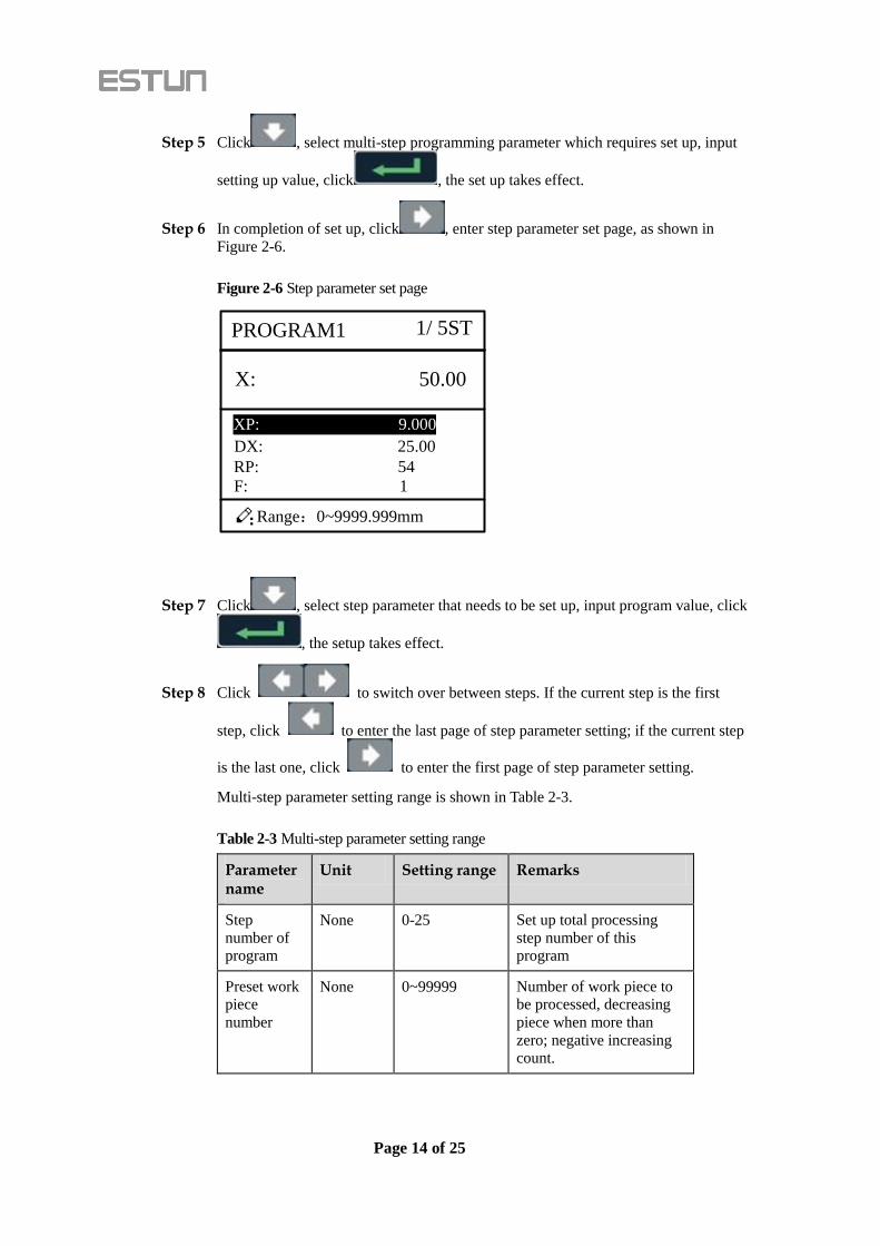
Step 6 In completion of set up, click , enter step parameter set page, as shown in
Figure 2-6.
Figure 2-6 Step parameter set page
X: 50.00
Range:0~9999.999mm
PROGRAM1
DX: 25.00
RP: 54
1/ 5ST
XP: 9.000
F: 1
Step 7 Click , select step parameter that needs to be set up, input program value, click
, the setup takes effect.
Step 8 Click to switch over between steps. If the current step is the first
step, click to enter the last page of step parameter setting; if the current step
is the last one, click to enter the first page of step parameter setting.
Multi-step parameter setting range is shown in Table 2-3.
Table 2-3 Multi-step parameter setting range
Parameter name
Unit Setting range Remarks
Step
number of
program
None 0-25 Set up total processing
step number of this
program
Preset work
piece
number
None 0~99999 Number of work piece to
be processed, decreasing
piece when more than
zero; negative increasing
count.

Page 15 of 25
Parameter name
Unit Setting range Remarks
Current
work piece
number
None 0~99999 Number of finished work
piece
Concession
delay
ms 0~99999ms Time between retract
signal and concession
execution.
X mm/inch None Current position of X axle,
can’t be modified.
X target
position
mm/inch 0~9999.999mm Program position of X
axle.
concession
distance
mm/inch 0~9999.999mm Distance of X axle
concession.
Repeat
times
None 1~99 Repeat times required by
this step.
F None 0~3 F function configure
output
Step 9 Click , system will operate according to this program, as shown in Figure
2-7.
Figure 2-7 Multi-step programming operation page
X: 5.000
PP: 20
C: 9
St: 1/ 1
PROGRAM 1 Rp:1/1
----End
Operation example
Requirements: one work piece requires processing 50 as shown below;
First shear: 50mm;
Second shear: 100mm;
Third shear: 300mm;
Analysis: according to work piece and technological conditions of machine tool:

Page 16 of 25
First shear: X axle position is 50.0mm, concession 50mm;
The second shear: X axle position is 100.0mm, concession 50mm;
The third shear: X axle position is 300.0mm, concession 50mm;
Edit processing program of this work piece on No. 2 program.
Operation procedure is shown in Table 2-4.
Table 2-4 Operation steps of multi-step programming example
Operation step
Operation
Step 1
On single step parameter setting page, press to
enter program selection page.
Step 2
Input “2”, click , enter multi-step general
parameter setting page of program 2.
Step 3
Select “Program step”, input “3”, click , the
setting takes effect.
Step 4
Select “PP”, input “50”, click , the setup
takes effect.
Step 5 Similar to step 3 and step 4, set “DLY” to 400
respectively.
Step 6
Click to enter first step setup page of step
parameter.
Step 7
Select “XP”, input 50, click , the setup takes
effect.
Step 8 Similar to step 7, set up “concession distance” and “repeat
times” to 50, 1 respectively.
Step 9
Click to enter second step setup page of step
parameter, the setup method is similar to that of step one.
Step 10
Click again, to enter third step setup page of step
parameter, the setup method is similar to that of step one
and step two.
Step11
Click , return to setup page of the first step.

Page 17 of 25
Operation step
Operation
Step12
Click , system will operate according to this
program.
In completion of multi-step programming, return to start step before launching the system;
otherwise, the program will start position processing at current step.
Press left and right direction key to circulate page turning and browsing among all step
parameters.
Program can be called and revised again.
In completion of processing all work pieces (50 in the example), system come to stop
automatically. Restart directly will start another round of processing 50 work pieces.
2.3 Parameter setting
User can setup all parameters required for normal operation of the system, including
system parameter, X axle parameter.
Operation steps
Step 1 On program management page, click to enter programming constant page,
as shown in Figure 2-8. On this page, programming constant can be set.
Figure 2-8 Programming constant page
CONST
mm/inch: 0
中文/English: 1
Version: V1.00
Range:0~9999.999mm
X-tea.in: 1.000
Range of programming constant setup is shown in Table 2-5.

Page 18 of 25
Table 2-5 Range of programming constant setup
Parameter name
Unit Setup range Default Remarks
X axle indexing mm 0-9999.99mm 0 In teach enable, input
current position of X
axle
Metric/English
system
None 0 or 1 0 0: Metric
1: English system
Chinese/English None 0 or 1 0 0: Chinese,
1: English
Version number None None None Software version
information, V refers to
version, 1 indicates
version number, and 0
indicates version level.
Step 2 Input password “94343”, click to enter system parameter setting page,
as shown in Figure 2-9.
Figure 2-9 System parameter setting page
SYS PARA 1/ 1PG
X-safe: 1.000
Step delay: 300
X-digits: 3
Range:0~3
Step 3 Step up parameter, parameter setup range is shown in Table 2-6.
Table 2-6 System parameter setup range
Parameter range
Unit Setup range Default Remarks
Decimal
point of X
axle
None 0-3 2 Decimal point displayed
by X axle position
parameter

Page 19 of 25
Parameter range
Unit Setup range Default Remarks
Safe
distance of
X axle
mm 0-9999.999mm 0 X axle keeps low speed in
this range
Change step
delay
ms 0-9999ms 0 Interval between valid
change step signal and
change step operation
executed
Step 4 Click , return to programming constant page.
----End
2.4 Manual movement
In single-step mode, axle movement can be controlled by pressing key manually.
This method helps user to adjust machine tool and work piece.
Operation steps
Step 1 On single step parameter setup page, click or to enter manual page,
as shown in Figure 2-10.
Figure 2-10 Manual page
MANUAL
X: 50.00
X current pos.
Step 2 Click , operate at low speed in increasing direction.
Click , operate at low speed in decreasing direction.
Click , click at the same time, operate at high speed in
increasing direction.

Page 20 of 25
Click , click at the same time, operate at high speed in
decreasing direction.
Step 3 Click return to single step parameter setting page.
----End

Page 21 of 25
3 Alarm
The device can detect internal or external abnormity automatically and send out
alarm prompt. Alarm message is available on alarm list.
Operation steps
Step 1 On programming management page, click to enter programming constant
page.
Step 2 On programming constant page, click to enter “Alarm history” page to view
all alarm history.
As shown in Figure 3-1, the latest 6 alarms, alarm number and causes can be viewed
on this page.
Figure 3-1 Alarm history page
A.24 Mach. Not ready
ALARM RECORD
Alarm history and message is shown in Table 3-1.
Table 3-1 Alarm number and alarm message
Alarm number Alarm name Alarm description
A.01 Count reached prompt Count reaches preset
value
A.02 Minimum soft limit Minimum soft limit
A.03 Maximum soft limit Maximum soft limit
Page 22 of 25
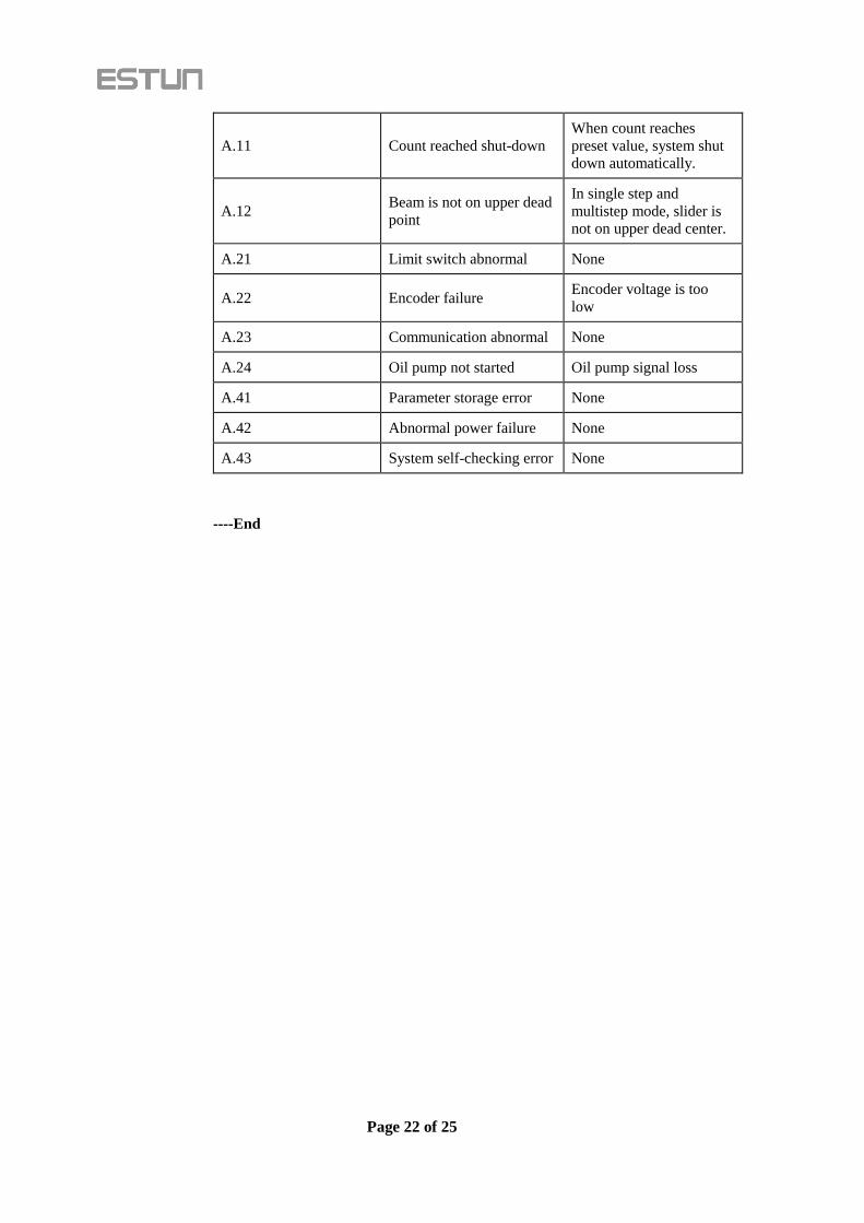
A.11 Count reached shut-down
When count reaches
preset value, system shut
down automatically.
A.12 Beam is not on upper dead
point
In single step and
multistep mode, slider is
not on upper dead center.
A.21 Limit switch abnormal None
A.22 Encoder failure Encoder voltage is too
low
A.23 Communication abnormal None
A.24 Oil pump not started Oil pump signal loss
A.41 Parameter storage error None
A.42 Abnormal power failure None
A.43 System self-checking error None
----End
Page 23 of 25
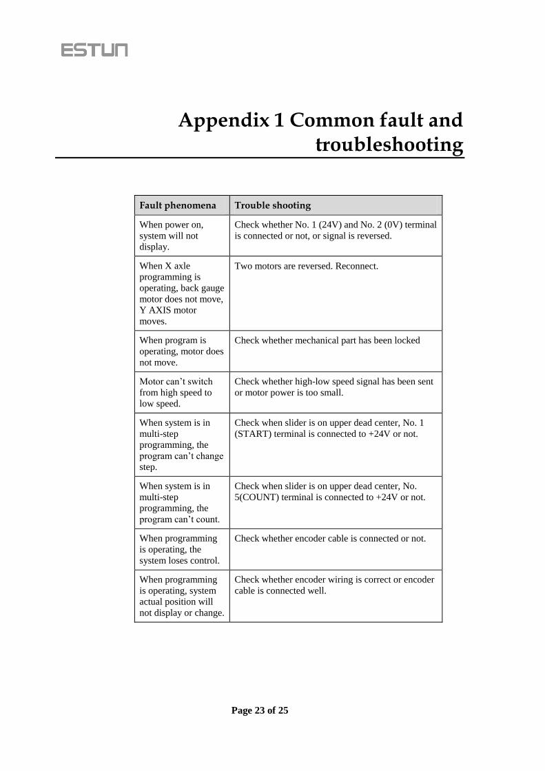
Appendix 1 Common fault and troubleshooting
Fault phenomena Trouble shooting
When power on,
system will not
display.
Check whether No. 1 (24V) and No. 2 (0V) terminal
is connected or not, or signal is reversed.
When X axle
programming is
operating, back gauge
motor does not move,
Y AXIS motor
moves.
Two motors are reversed. Reconnect.
When program is
operating, motor does
not move.
Check whether mechanical part has been locked
Motor can’t switch
from high speed to
low speed.
Check whether high-low speed signal has been sent
or motor power is too small.
When system is in
multi-step
programming, the
program can’t change
step.
Check when slider is on upper dead center, No. 1
(START) terminal is connected to +24V or not.
When system is in
multi-step
programming, the
program can’t count.
Check when slider is on upper dead center, No.
5(COUNT) terminal is connected to +24V or not.
When programming
is operating, the
system loses control.
Check whether encoder cable is connected or not.
When programming
is operating, system
actual position will
not display or change.
Check whether encoder wiring is correct or encoder
cable is connected well.

Page 25 of 25
Appendix 2 Acronym
Acronym English interpretation
C
C COUNT
CP Current Pieces
D
DX Retract
DLY Delay time
F
F Function
P
PP Preset Pieces
S
ST STEP
X
X X-axis
XP X-axis position