SHEAR STRENGTH CHARACTERISTICS OF MAKINO BAMBOO SOIL… · SHEAR STRENGTH CHARACTERISTICS OF MAKINO...
16
SHEAR STRENGTH CHARACTERISTICS OF MAKINO BAMBOO SOIL/ROOT SYSTEM Der-Guey Lin 1* , Bor-Shun Huang 2 , Shin-Hwei Lin 3 ABSTRACT According to the field investigations of Makino bamboo (Phyllostachys makinoi Hayata) root morphology, a numerical model of soil-root system consisted of T-shape tap root and hair roots were developed for the numerical simulation of in-situ pull-out tests. Using the identical numerical model with the pull-out test, the shear strength increment of soil mass due to roots can be evaluated through a series of numerical simulations of direct shear test. Eventually, a mechanical conversion model with simple mathematic form which enables a direct transformation of the ultimate pull-out resistance into the shear strength increment of soil-root system was proposed. The conversion model offered a convenient way to quantify the effect of reinforcement of Makino bamboo root system required for the slope stability analyses. Keywords: Makino bamboo, Pull-out test, Soil-root system, Mechanical conversion model INTRODUCTION In slope engineering, vegetation was frequently incorporated with different construction methods as an auxiliary approach for slope stabilization. Currently, in Taiwan the Makino bamboo was the most predominant among several major species of bamboo because it was selected as one of the important plant for forest plantation. The root system of Makino bamboo was considered as a stabilizing source to the slopeland of watershed. In Taiwan, the relevant studies of Makino bamboo were mainly concentrated on its′ growth characteristics, biomass investigations, population distributions, and utilizations rather than their mechanical properties and slope stabilizing mechanism. Previously, a large amount of direct shear tests and mechanical models of soil-root interaction were carried out and proposed to quantify the reinforcement effect of root system on soil mass (Waldron L. J., 1977; Waldron L. J. and Dakessian S., 1981; Wu T. H. 1979, 1988 a & b; Abe K. and Ziemer R. R., 1991b; Operstein V. and Frydman S., 2000; Cazzuffi D. and Crippa E., 2005). Models of soil-root interaction were proposed for evaluating the contribution of roots to shear strength and comprehensive reviews can be found in many works (Coppin N. J. and Richards I. G., 1990; Morgan R. P. C. and Rickson R. J., 1995; Gray D. H. and Sotir, R. B., 1996; Wu T.H. et al., 2004). However, the studies on mechanical properties and the reinforcement effect of bamboo roots with shallow distribution depth and large growth height were remaining rare. 1 Associate professor, Department of Soil and Water conservation, National Chung-Hsing University, Taichung, 40227, Taiwan, R.O.C. (*Corresponding Author; Tel.: +886-4-2284-0381 ext 506; Fax: +886-4-2287-6851; Email: [email protected]) 2 Doctoral Student, Department of Soil and Water Conservation, National Chung-Hsing University, Taichung, 40227, Taiwan, R.O.C. 3 Professor, Department of Soil and Water Conservation National Chung-Hsing University, Taichung, 40227, Taiwan, R.O.C. -496-
Transcript of SHEAR STRENGTH CHARACTERISTICS OF MAKINO BAMBOO SOIL… · SHEAR STRENGTH CHARACTERISTICS OF MAKINO...
SHEAR STRENGTH CHARACTERISTICS OF MAKINO BAMBOO SOIL/ROOT SYSTEM
Der-Guey Lin1*, Bor-Shun Huang2, Shin-Hwei Lin3
ABSTRACT According to the field investigations of Makino bamboo (Phyllostachys makinoi Hayata) root morphology, a numerical model of soil-root system consisted of T-shape tap root and hair roots were developed for the numerical simulation of in-situ pull-out tests. Using the identical numerical model with the pull-out test, the shear strength increment of soil mass due to roots can be evaluated through a series of numerical simulations of direct shear test. Eventually, a mechanical conversion model with simple mathematic form which enables a direct transformation of the ultimate pull-out resistance into the shear strength increment of soil-root system was proposed. The conversion model offered a convenient way to quantify the effect of reinforcement of Makino bamboo root system required for the slope stability analyses. Keywords: Makino bamboo, Pull-out test, Soil-root system, Mechanical conversion model INTRODUCTION In slope engineering, vegetation was frequently incorporated with different construction methods as an auxiliary approach for slope stabilization. Currently, in Taiwan the Makino bamboo was the most predominant among several major species of bamboo because it was selected as one of the important plant for forest plantation. The root system of Makino bamboo was considered as a stabilizing source to the slopeland of watershed. In Taiwan, the relevant studies of Makino bamboo were mainly concentrated on its′ growth characteristics, biomass investigations, population distributions, and utilizations rather than their mechanical properties and slope stabilizing mechanism. Previously, a large amount of direct shear tests and mechanical models of soil-root interaction were carried out and proposed to quantify the reinforcement effect of root system on soil mass (Waldron L. J., 1977; Waldron L. J. and Dakessian S., 1981; Wu T. H. 1979, 1988 a & b; Abe K. and Ziemer R. R., 1991b; Operstein V. and Frydman S., 2000; Cazzuffi D. and Crippa E., 2005). Models of soil-root interaction were proposed for evaluating the contribution of roots to shear strength and comprehensive reviews can be found in many works (Coppin N. J. and Richards I. G., 1990; Morgan R. P. C. and Rickson R. J., 1995; Gray D. H. and Sotir, R. B., 1996; Wu T.H. et al., 2004). However, the studies on mechanical properties and the reinforcement effect of bamboo roots with shallow distribution depth and large growth height were remaining rare.
1 Associate professor, Department of Soil and Water conservation, National Chung-Hsing University, Taichung,
40227, Taiwan, R.O.C. (*Corresponding Author; Tel.: +886-4-2284-0381 ext 506; Fax: +886-4-2287-6851; Email: [email protected])
2 Doctoral Student, Department of Soil and Water Conservation, National Chung-Hsing University, Taichung, 40227, Taiwan, R.O.C.
3 Professor, Department of Soil and Water Conservation National Chung-Hsing University, Taichung, 40227, Taiwan, R.O.C.
-496-
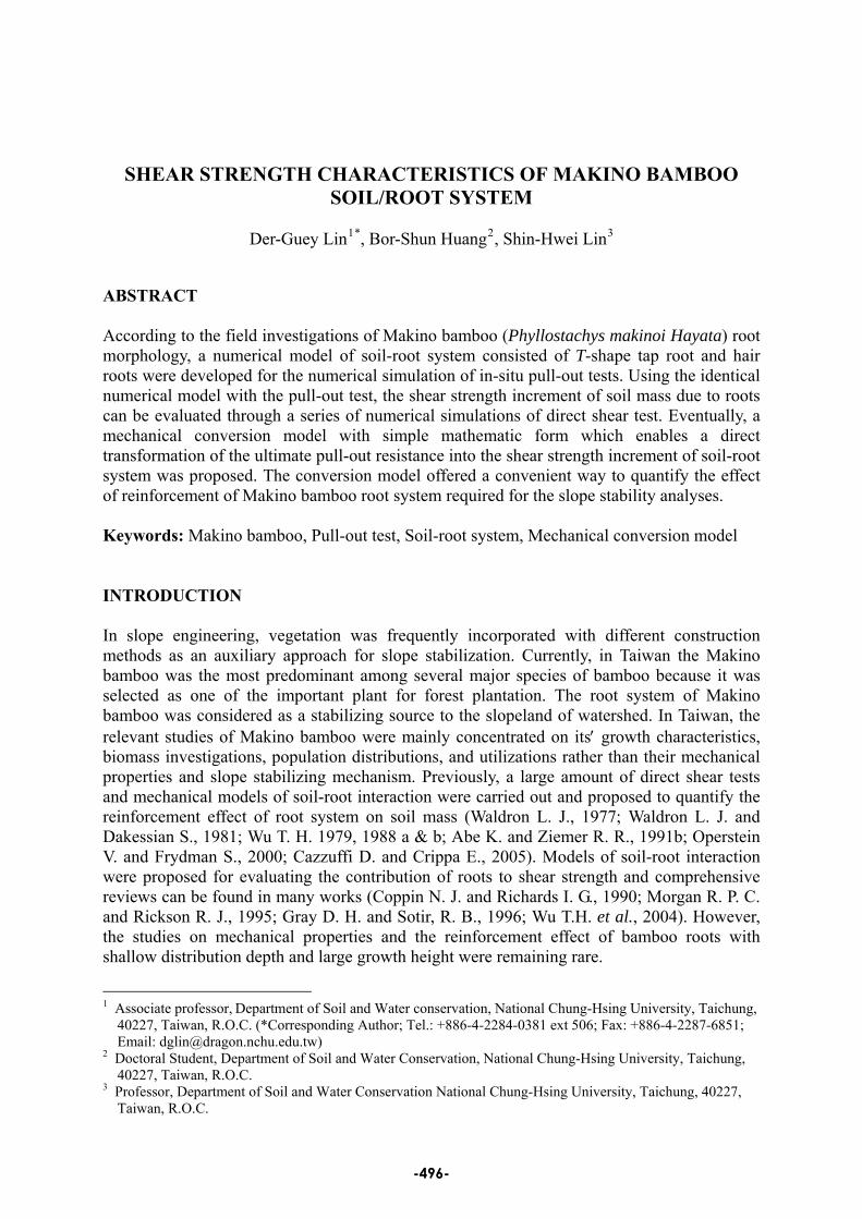
The major objectives of this study are aimed to develop a mechanical conversion model to evaluate the shear strength increment of soil mass due to Makino bamboo roots directly based on the ultimate pull-out resistance of root system. In this study, several representative test pits were excavated in the field to survey the morphology of Makino bamboo root system and a series of in-situ pull-out test were carried out to evaluate the anchorage resistance of roots. Based on the morphology of root system and the mechanical properties of root material, one can establish a 3-D numerical model of Makino bamboo soil-root system for the simulations of in-situ pull-out test. Subsequently, the identical 3-D numerical model with the pull-out test was repeatedly used for the simulation of direct shear test to evaluate the shear strength increment of soil mass due to roots. Eventually, a mechanical conversion model which enables a direct transformation of the ultimate pull-out resistance into the shear strength increment of Makino bamboo soil-root system was proposed. INVESTIGATIONS ON MAKINO BAMBOO ROOT SYSTEM The morphology of root system Several test pits were excavated in the field site to survey the morphology of Makino bamboo root system as shown in Fig. 1. The diameter at breast height (DBH) of Makino bamboo ranged from 50 to 60 mm and the growth age was 2~3 years in average.
(a) slope land
(b) plane land
Fig. 1 Test pits and survey of the morphology of Makino bamboo root system
The root system of Makino bamboo (Phyllostachys makinoi Hayata) was mainly composed of
-497-
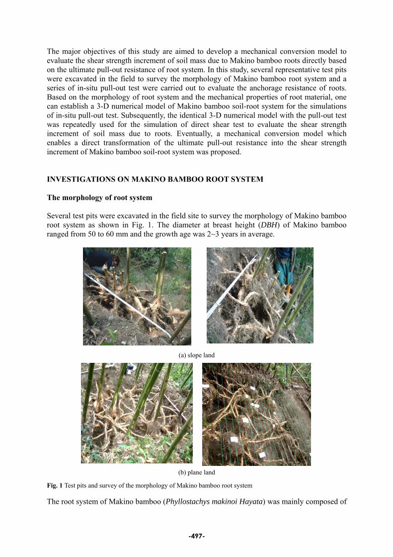
a reverse T-shape tap root (or vertical tap root + lateral tap root) and plenty of hair roots as presented in Fig. 2. The vertical tap root extends downward to a depth of around 10~30 cm (=LVT) and grows laterally to a range of about 40~50 cm (=LLT). The average diameter of tap root ranges from 1.3 to 2.5 cm (=d). In addition, the hair root of Makino bamboo sprouts from the knot of the lateral tap root and widely spreads over the soil layers adjacent to the ground surface. The biomass of the hair root is around 2~3 times of that of usual plants and it decreases with the increase of depth. The average diameter of hair root is about 0.1~0.2 cm (=d) and the stretching length can reach to 60 cm (=LVH or LLH). In general, the root system of Makino bamboo can grow and extend downward to a depth of around 80~100 cm from ground surface.
Reverse T-shape tap root (=Vertical tap root LVT +
Lateral tap root LLT)
Vertical hair root LVH
Lateral hair root LLH
Fig. 2 Illustration of the morphology of Makino bamboo root system Laboratory tests of root strength
According to the tensile and shearing tests of single root, the average tensile resistance of Makino bamboo single root, t, can be approximated by t (kN)=[1.85×d 2.03] for root diameter d (cm) =1.35~ 2.36 cm. Moreover, the average Young′s modulus of Makino bamboo tap root material Er=193.3~451.3 kPa was determined from the 30 stress/strain curves of tensile tests. Table 1 summarized the laboratory testing results of tap root materials.
Table 1 Average tensile and shear strengths of Makino bamboo single root
Root material type Average diameter d (cm) Average tensile strength σt (MN/m2)
Live cutting 2.4~2.2 36.87~26.97
Live cutting 2.1~1.9 16.57~14.02
Live cutting 1.8~1.4 8.24~5.79
Dead dry 2.3~1.9 13.53~10.40
Root material type Average diameter (cm) Average shear strength τ (MN/m2)
Live cutting 2.3~1.9 13.53~10.40 In-situ pull-out tests of soil/root system The field site of pull-out test located on the Da-Xi forest land No. 167, Fu-Hsing Township, Tao-Yen County, Taiwan and attributed to the watershed of Si-Men reservoir. The soil
-498-
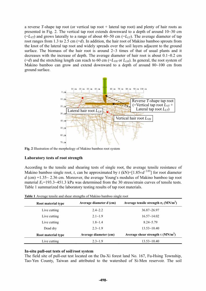
material was classified into silty clay (CL) or silty soil (ML) by United Soil Classification System and the strength parameters were summarized as: cohesion c=24 kPa; friction angle φ=15.6°. The average saturated and unsaturated unit weights of soil stratum were 19.0 and 18.0 kN/m3 respectively. The average water content of soil samples were about 7% in dry season and 45% in rainy season. The growth age of Makino bamboo for the pull-out test ranged from 1 yr to 3 yrs. Based on the pull-out tests of Makino bamboo root system, the ultimate pull-out resistance can be given by Pu (kN)= (58.99×D +77.08×n). In which, D=the diameter at breast height (DBH= 3.3~7.0 cm) and n=the number of breaking tap root (=1~4). Figure 3 shows the uprooted root system at final testing stage.
Fig. 3 Uprooting of Makino bamboo root system after pull-out test NUMERICAL SIMULATION OF PULL-OUT TEST Abe K. (1991) estimated the reinforced shear resistance of roots through the pull-out resistance of roots. Operstein V. and Frydman S. (2000) carried out 43 pull-out tests to measure the vertical pull-out load of alfalfa roots from a waste chalky fill, with varying stone content. Lin et al. (2005) summarized the testing results of various types of mechanical tests in soil-root system and it was indicated that the pull-out resistance of soil-root system was influenced by the climate change, soil properties, and the growth age of the plant. Conclusively, the morphology of plant roots in soil stratum dominates the anchorage of plant to resist the uprooting force (Stokes A. et al., 1996; Ennos A.R., 1990 and 1991). Dupuy L. et al. (2005) used the density-based approach to model the architecture of roots and investigated the anchorage of roots by two-dimensional (2-D) numerical analyses. This study performed a series of 3-D finite element analyses to simulate the pull-out behaviors of Makino bamboo root system. The numerical results of pull-out force versus pull-out displacement curves were compared with those from the field measurements to verify the effectiveness of numerical procedures. Eventually, an optimum artificial geometry configuration can be determined to represent the natural morphology of Makino bamboo root system.
-499-
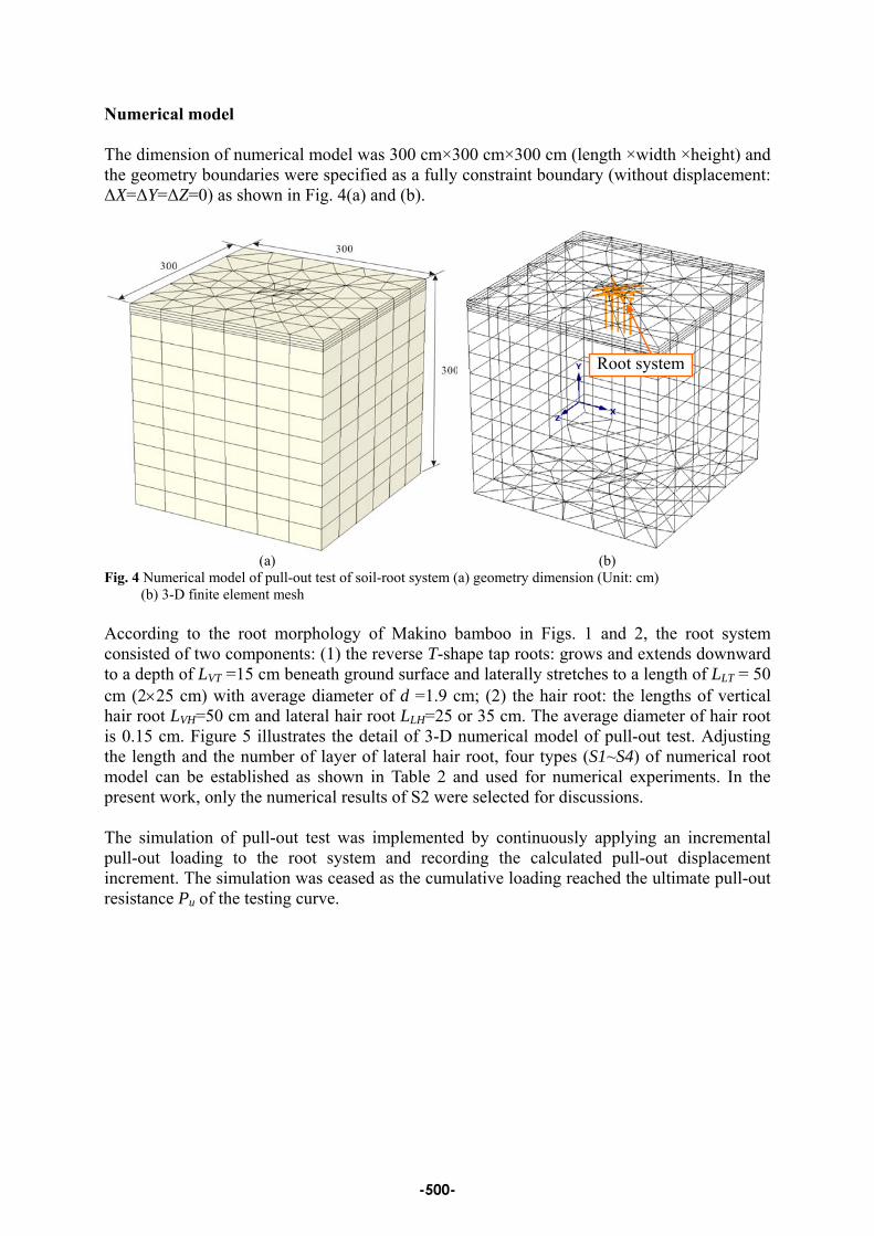
Numerical model The dimension of numerical model was 300 cm×300 cm×300 cm (length ×width ×height) and the geometry boundaries were specified as a fully constraint boundary (without displacement: ΔX=ΔY=ΔZ=0) as shown in Fig. 4(a) and (b).
Root system
(a) (b) Fig. 4 Numerical model of pull-out test of soil-root system (a) geometry dimension (Unit: cm)
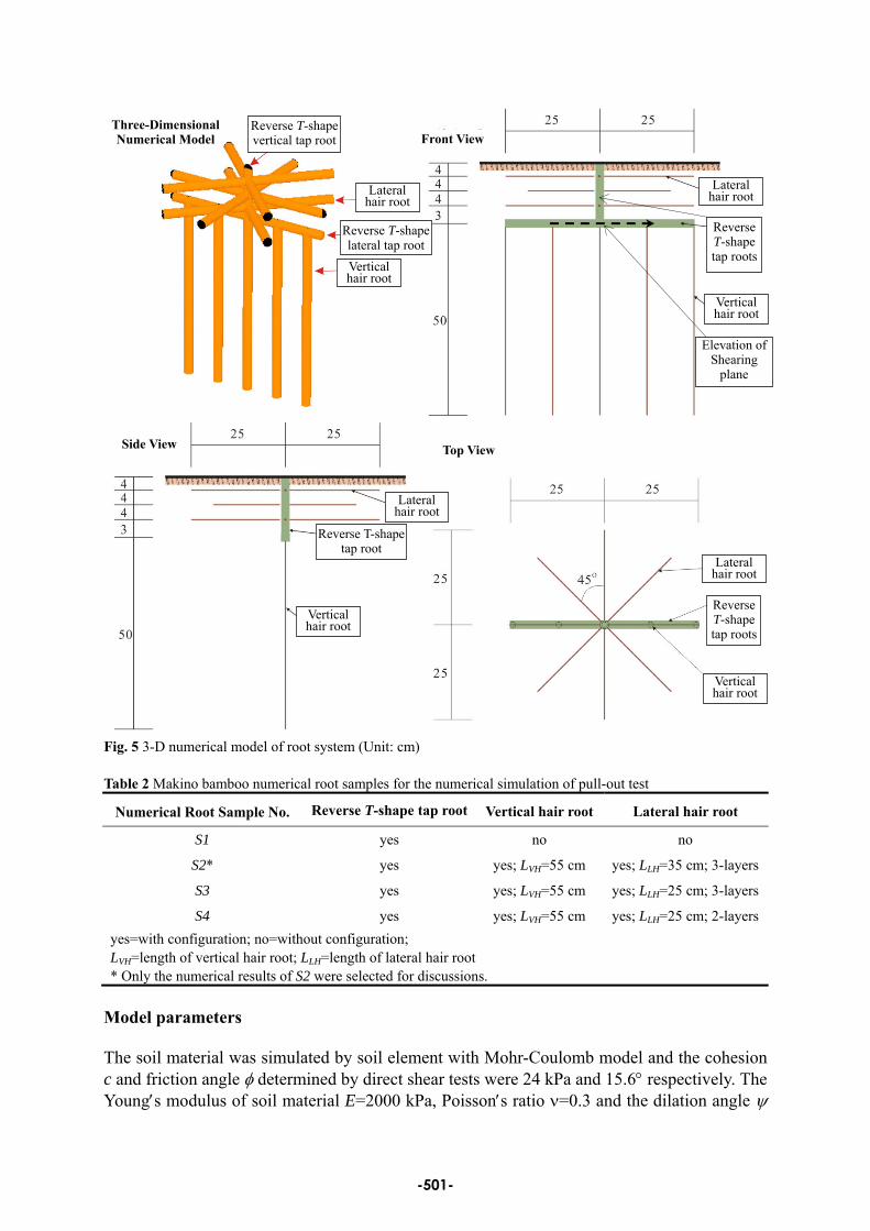
(b) 3-D finite element mesh According to the root morphology of Makino bamboo in Figs. 1 and 2, the root system consisted of two components: (1) the reverse T-shape tap roots: grows and extends downward to a depth of LVT =15 cm beneath ground surface and laterally stretches to a length of LLT = 50 cm (2×25 cm) with average diameter of d =1.9 cm; (2) the hair root: the lengths of vertical hair root LVH=50 cm and lateral hair root LLH=25 or 35 cm. The average diameter of hair root is 0.15 cm. Figure 5 illustrates the detail of 3-D numerical model of pull-out test. Adjusting the length and the number of layer of lateral hair root, four types (S1~S4) of numerical root model can be established as shown in Table 2 and used for numerical experiments. In the present work, only the numerical results of S2 were selected for discussions. The simulation of pull-out test was implemented by continuously applying an incremental pull-out loading to the root system and recording the calculated pull-out displacement increment. The simulation was ceased as the cumulative loading reached the ultimate pull-out resistance Pu of the testing curve.
-500-
Three-Dimensional Numerical Model Front View
Reverse T-shape vertical tap root
Lateral hair root
Reverse T-shape lateral tap rootVerticalhair root
Side View Top View
Reverse T-shape tap root
Lateral hair root
Vertical hair root
Reverse T-shape tap roots
Lateral hair root
Verticalhair root
Lateral hair root
Reverse T-shape tap roots
Verticalhair root
Elevation of Shearing
plane
Fig. 5 3-D numerical model of root system (Unit: cm) Table 2 Makino bamboo numerical root samples for the numerical simulation of pull-out test
Numerical Root Sample No. Reverse T-shape tap root Vertical hair root Lateral hair root
S1 yes no no
S2* yes yes; LVH=55 cm yes; LLH=35 cm; 3-layers
S3 yes yes; LVH=55 cm yes; LLH=25 cm; 3-layers
S4 yes yes; LVH=55 cm yes; LLH=25 cm; 2-layersyes=with configuration; no=without configuration; LVH=length of vertical hair root; LLH=length of lateral hair root * Only the numerical results of S2 were selected for discussions.
Model parameters The soil material was simulated by soil element with Mohr-Coulomb model and the cohesion c and friction angle φ determined by direct shear tests were 24 kPa and 15.6° respectively. The Young′s modulus of soil material E=2000 kPa, Poisson′s ratio ν=0.3 and the dilation angle ψ
-501-
=0° were specified based on the engineering characteristics of low plasticity silty clay or silty soil (CL~ML). In addition, the relative displacement at soil-root interface during the pull-out test was modeled by two strength parameters cint and φint. At the interface, the cint and φint were given by: cint (=Rint×c) and φint (=Rint×[tan-1tanφ]), in which, the strength reduction factor Rint= 0.5 was adopted. The root material was simulated by ground anchor element with linear elastic model. The ultimate tensile resistance of single root t was determined by 1.85×d 2.03 (see in previous paragraph) of 6.81 kN and 3.93 kN for tap root diameter d=1.9 cm and hair root diameter d=0.15 cm respectively. In addition, the average Young′s modulus of root material Er=312 kPa was used for the numerical simulation. Table 3 presents the required input model parameters of soil and root materials. Table 3 Material model parameters of (a) soil stratum (b) root system for the pull-out test simulation (a)
Soil model c (kPa) φ (deg.) γsat (kN/m3) E (kPa) ν ψ (deg.) Mohr-Coulomb model 24 15.6 19.0 2000 0.3 0
(b)
Root system Root diameter d (cm) Cross sectional area a (cm2) Ultimate tensile resistance t (kN)
Tap root 1.90 2.835 6.81 Hair root 0.15 0.018 3.93
Young′s modulus Er=312 kPa for root system NUMERICAL SIMULATION OF DIRECT SHEAR TEST Operstrin V., Frydman S. (2001) simulated the direct shear behavior of cylindrical samples with and without root using 2-D finite difference plane strain numerical scheme to examine the reinforcement effect of roots. However, it needed some numerical skills to convert the 3-D problem into 2-D. In this study, the identical 3-D numerical model with the pull-out test of Makino bamboo soil-root system was used for the simulation of direct shear test. In such way, the shear strength increment of soil mass due to roots, ΔSr, can be determined from the numerical results and eventually correlated with the ultimate pull-out resistance Pu.
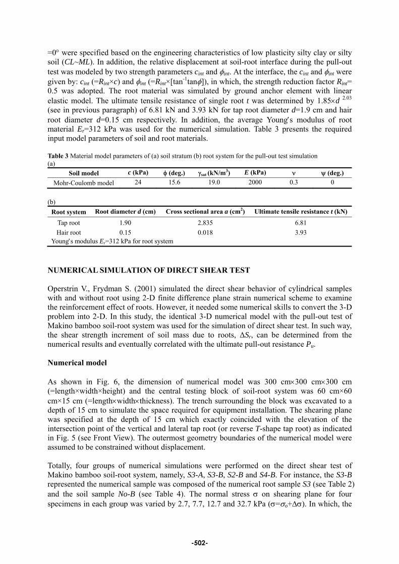
Numerical model As shown in Fig. 6, the dimension of numerical model was 300 cm×300 cm×300 cm (=length×width×height) and the central testing block of soil-root system was 60 cm×60 cm×15 cm (=length×width×thickness). The trench surrounding the block was excavated to a depth of 15 cm to simulate the space required for equipment installation. The shearing plane was specified at the depth of 15 cm which exactly coincided with the elevation of the intersection point of the vertical and lateral tap root (or reverse T-shape tap root) as indicated in Fig. 5 (see Front View). The outermost geometry boundaries of the numerical model were assumed to be constrained without displacement. Totally, four groups of numerical simulations were performed on the direct shear test of Makino bamboo soil-root system, namely, S3-A, S3-B, S2-B and S4-B. For instance, the S3-B represented the numerical sample was composed of the numerical root sample S3 (see Table 2) and the soil sample No-B (see Table 4). The normal stress σ on shearing plane for four specimens in each group was varied by 2.7, 7.7, 12.7 and 32.7 kPa (σ=σo+Δσ). In which, the
-502-
overburden stressσo=0.15 m×18 kN/m3=2.7 kPa and the normal stress increment Δσ=0, 5, 10 and 30 kPa. The shear loading increment was applied continuously on the steel plate of shear box and finally ceased as the shear stress on shearing plane reach the peak value.
Central testing block
Soil-root system
Fig. 6 Numerical model for the direct shear test of soil-root system (a) geometry dimension (Unit: cm) (b) 3-D finite element mesh
Model parameters Two sets of soil model parameters were adopted for the numerical simulation of direct shear test as presented in Table 4. Soil sample No-A was same as that of the pull-out test (see Table 3(a)). Soil sample No-B was similar to No-A only different in c (=25 kPa) and φ (=30°) values. The root material parameters were same as those of pull-out test (see Table 3(b)). In addition, as shown in Fig. 7, the direct shear box of steel plate was simulated by wall element with linear elastic model and the model parameters were listed in Table 5. Table 4 Soil model parameters for the numerical simulation of direct shear test of soil-root system
Soil Sample Soil model c (kPa) φ (deg.) γsat (kN/m3) E (kPa) ν ψ (deg.)
No-A Mohr-Coulomb model 24 15.6 19.0 2000 0.3 0
No-B* Mohr-Coulomb model 25 30.0 19.0 2000 0.3 0 * Soil sample No. B was selected for the presentation of direct shear test and slope stability analyses
Table 5 Material parameters of steel plate shear box
Element type
Thickness ts (cm)
Young′s modulus Es (GPa)
Unit weight γs (kN/m3)
Poisson′s ratio νs
Wall element 2.0 200 78.5 0.29
-503-
Steel direct shear box
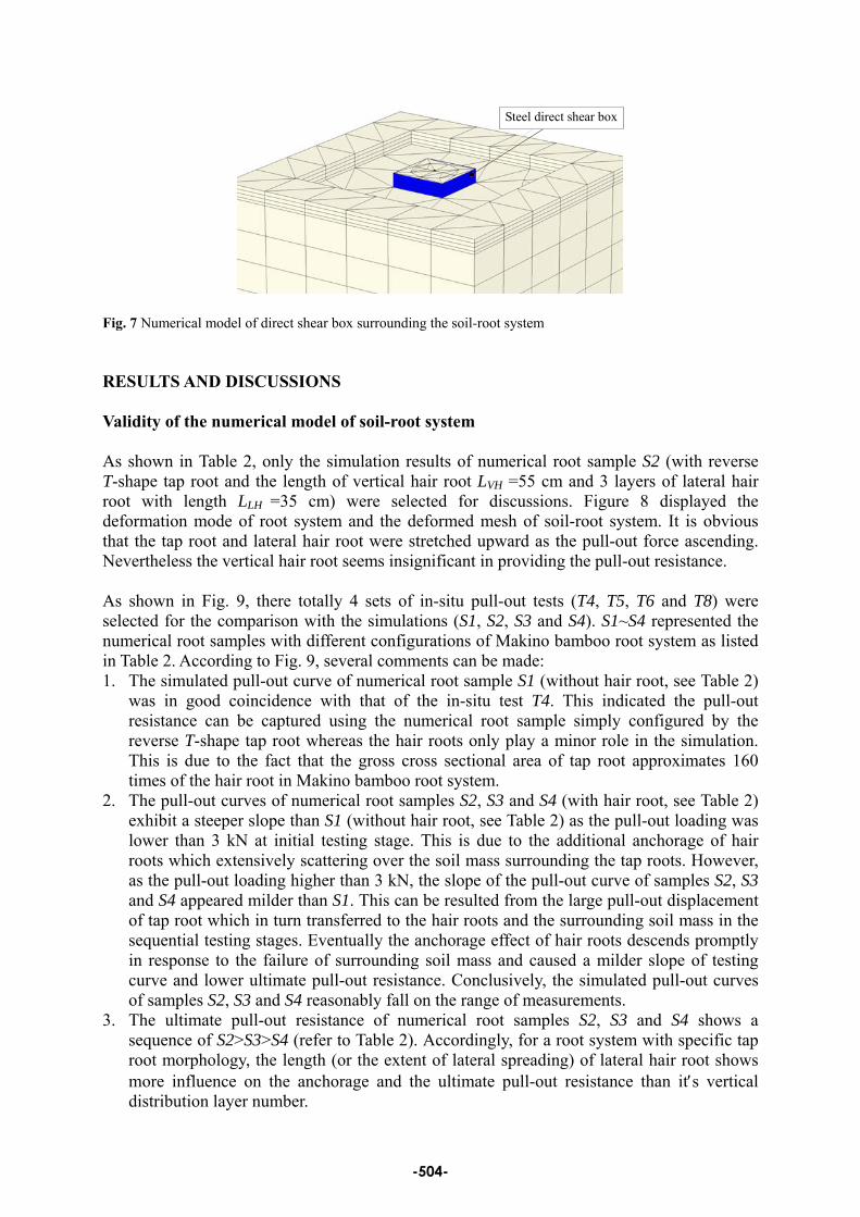
Fig. 7 Numerical model of direct shear box surrounding the soil-root system RESULTS AND DISCUSSIONS Validity of the numerical model of soil-root system
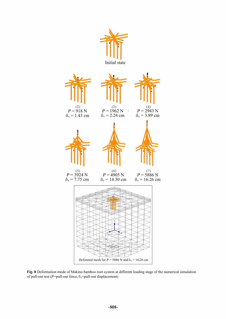
As shown in Table 2, only the simulation results of numerical root sample S2 (with reverse T-shape tap root and the length of vertical hair root LVH =55 cm and 3 layers of lateral hair root with length LLH =35 cm) were selected for discussions. Figure 8 displayed the deformation mode of root system and the deformed mesh of soil-root system. It is obvious that the tap root and lateral hair root were stretched upward as the pull-out force ascending. Nevertheless the vertical hair root seems insignificant in providing the pull-out resistance.
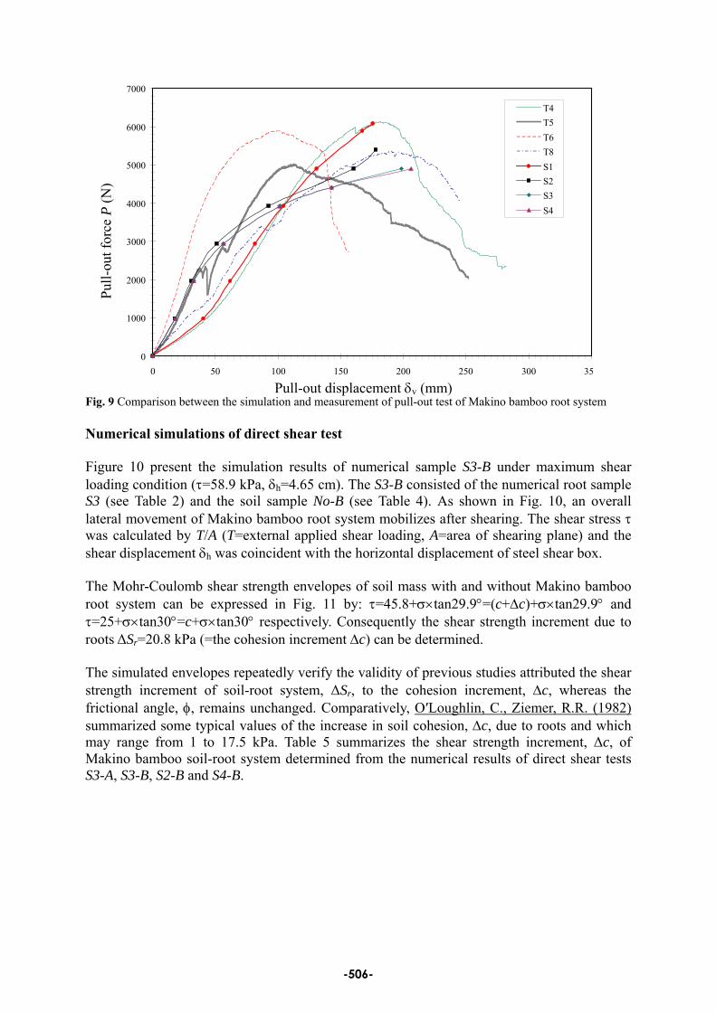
As shown in Fig. 9, there totally 4 sets of in-situ pull-out tests (T4, T5, T6 and T8) were selected for the comparison with the simulations (S1, S2, S3 and S4). S1~S4 represented the numerical root samples with different configurations of Makino bamboo root system as listed in Table 2. According to Fig. 9, several comments can be made: 1. The simulated pull-out curve of numerical root sample S1 (without hair root, see Table 2)
was in good coincidence with that of the in-situ test T4. This indicated the pull-out resistance can be captured using the numerical root sample simply configured by the reverse T-shape tap root whereas the hair roots only play a minor role in the simulation. This is due to the fact that the gross cross sectional area of tap root approximates 160 times of the hair root in Makino bamboo root system.
2. The pull-out curves of numerical root samples S2, S3 and S4 (with hair root, see Table 2) exhibit a steeper slope than S1 (without hair root, see Table 2) as the pull-out loading was lower than 3 kN at initial testing stage. This is due to the additional anchorage of hair roots which extensively scattering over the soil mass surrounding the tap roots. However, as the pull-out loading higher than 3 kN, the slope of the pull-out curve of samples S2, S3 and S4 appeared milder than S1. This can be resulted from the large pull-out displacement of tap root which in turn transferred to the hair roots and the surrounding soil mass in the sequential testing stages. Eventually the anchorage effect of hair roots descends promptly in response to the failure of surrounding soil mass and caused a milder slope of testing curve and lower ultimate pull-out resistance. Conclusively, the simulated pull-out curves of samples S2, S3 and S4 reasonably fall on the range of measurements.
3. The ultimate pull-out resistance of numerical root samples S2, S3 and S4 shows a sequence of S2>S3>S4 (refer to Table 2). Accordingly, for a root system with specific tap root morphology, the length (or the extent of lateral spreading) of lateral hair root shows more influence on the anchorage and the ultimate pull-out resistance than it′s vertical distribution layer number.
-504-
Initial state
Fig. 8 Deformation mode of Makino bamboo root system at different loading stage of the numerical simulation of pull-out test (P=pull-out force, δv=pull-out displacement)
P = 918 N δv = 1.43 cm
P = 1962 Nδv = 2.24 cm
P = 2943 Nδv = 3.89 cm
P = 3924 N δv = 7.75 cm
P = 4905 N P = 5886 Nδv = 14.30 cm δv = 16.26 cm
Deformed mesh for P = 5886 N and δv = 16.26 cm
-505-
0
1000
2000
3000
4000
5000
6000
7000
0 50 100 150 200 250 300 35
T4T5T6T8S1S2S3S4
Pull-
out f
orce
P (N
)
Fig. 9 Comparison between the simulation and measurement of pull-out test of Makino bamboo root system
Pull-out displacement δv (mm)
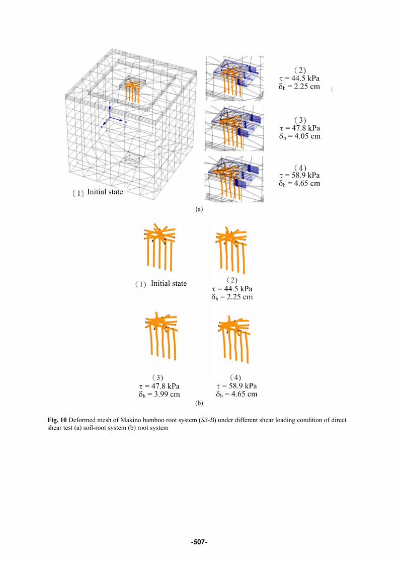
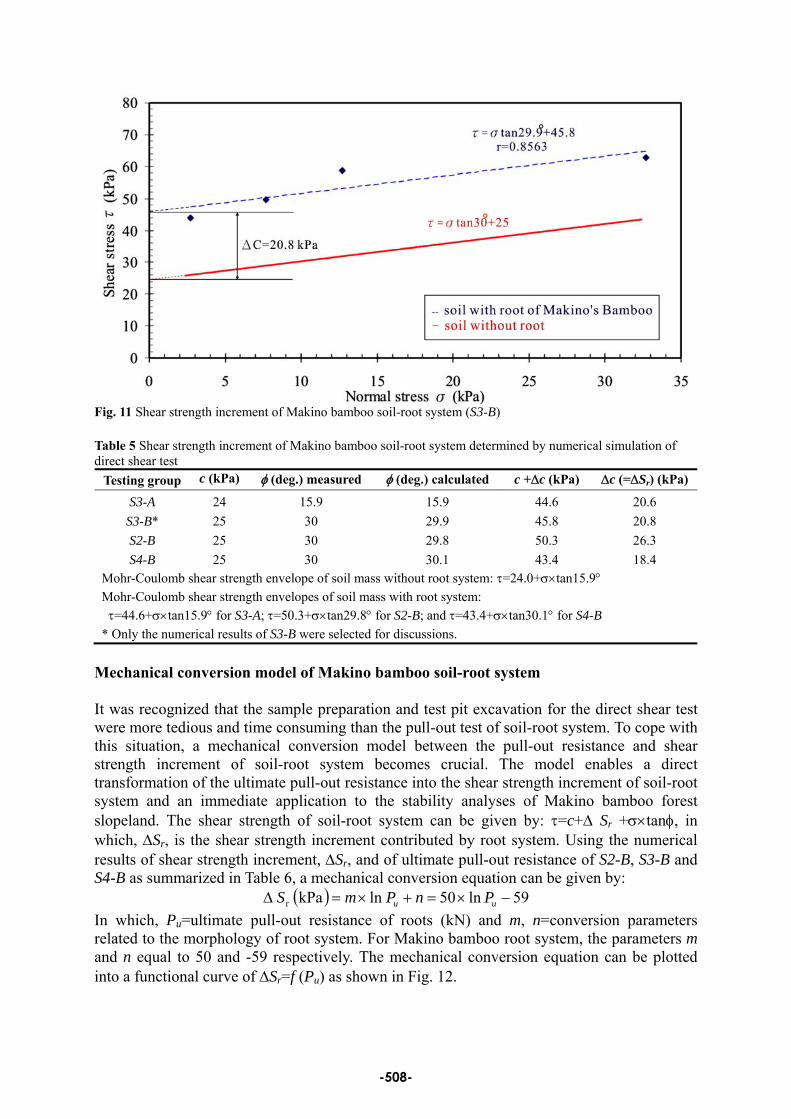
Numerical simulations of direct shear test Figure 10 present the simulation results of numerical sample S3-B under maximum shear loading condition (τ=58.9 kPa, δh=4.65 cm). The S3-B consisted of the numerical root sample S3 (see Table 2) and the soil sample No-B (see Table 4). As shown in Fig. 10, an overall lateral movement of Makino bamboo root system mobilizes after shearing. The shear stress τ was calculated by T/A (T=external applied shear loading, A=area of shearing plane) and the shear displacement δh was coincident with the horizontal displacement of steel shear box. The Mohr-Coulomb shear strength envelopes of soil mass with and without Makino bamboo root system can be expressed in Fig. 11 by: τ=45.8+σ×tan29.9°=(c+Δc)+σ×tan29.9° and τ=25+σ×tan30°=c+σ×tan30° respectively. Consequently the shear strength increment due to roots ΔSr=20.8 kPa (=the cohesion increment Δc) can be determined. The simulated envelopes repeatedly verify the validity of previous studies attributed the shear strength increment of soil-root system, ΔSr, to the cohesion increment, Δc, whereas the frictional angle, φ, remains unchanged. Comparatively, O′Loughlin, C., Ziemer, R.R. (1982) summarized some typical values of the increase in soil cohesion, Δc, due to roots and which may range from 1 to 17.5 kPa. Table 5 summarizes the shear strength increment, Δc, of Makino bamboo soil-root system determined from the numerical results of direct shear tests S3-A, S3-B, S2-B and S4-B.
-506-
τ = 44.5 kPa δh = 2.25 cm
τ = 47.8 kPa δh = 4.05 cm
τ = 58.9 kPa δh = 4.65 cm
Initial state
(a)
(b)
Initial stateτ = 44.5 kPaδh = 2.25 cm
τ = 47.8 kPaδh = 3.99 cm
τ = 58.9 kPaδh = 4.65 cm
Fig. 10 Deformed mesh of Makino bamboo root system (S3-B) under different shear loading condition of direct shear test (a) soil-root system (b) root system
-507-
°
°
Fig. 11 Shear strength increment of Makino bamboo soil-root system (S3-B) Table 5 Shear strength increment of Makino bamboo soil-root system determined by numerical simulation of direct shear test
Testing group c (kPa) φ (deg.) measured φ (deg.) calculated c +Δc (kPa) Δc (=ΔSr) (kPa)
S3-A 24 15.9 15.9 44.6 20.6 S3-B* 25 30 29.9 45.8 20.8 S2-B 25 30 29.8 50.3 26.3 S4-B 25 30 30.1 43.4 18.4
Mohr-Coulomb shear strength envelope of soil mass without root system: τ=24.0+σ×tan15.9° Mohr-Coulomb shear strength envelopes of soil mass with root system: τ=44.6+σ×tan15.9° for S3-A; τ=50.3+σ×tan29.8° for S2-B; and τ=43.4+σ×tan30.1° for S4-B
* Only the numerical results of S3-B were selected for discussions. Mechanical conversion model of Makino bamboo soil-root system
It was recognized that the sample preparation and test pit excavation for the direct shear test were more tedious and time consuming than the pull-out test of soil-root system. To cope with this situation, a mechanical conversion model between the pull-out resistance and shear strength increment of soil-root system becomes crucial. The model enables a direct transformation of the ultimate pull-out resistance into the shear strength increment of soil-root system and an immediate application to the stability analyses of Makino bamboo forest slopeland. The shear strength of soil-root system can be given by: τ=c+Δ Sr +σ×tanφ, in which, ΔSr, is the shear strength increment contributed by root system. Using the numerical results of shear strength increment, ΔSr, and of ultimate pull-out resistance of S2-B, S3-B and S4-B as summarized in Table 6, a mechanical conversion equation can be given by:
( ) 59ln50 lnkPa r −×=+×=Δ uu PnPmS In which, Pu=ultimate pull-out resistance of roots (kN) and m, n=conversion parameters related to the morphology of root system. For Makino bamboo root system, the parameters m and n equal to 50 and -59 respectively. The mechanical conversion equation can be plotted into a functional curve of ΔSr=f (Pu) as shown in Fig. 12.
-508-
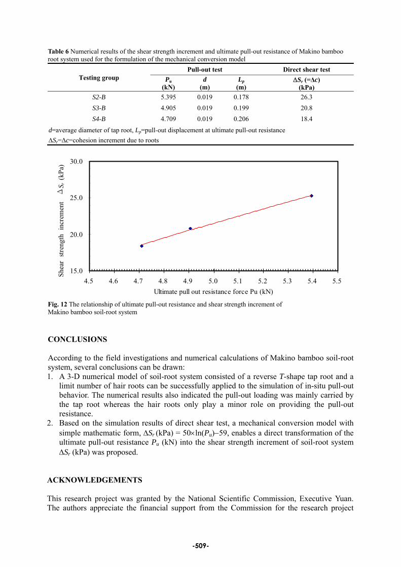
Table 6 Numerical results of the shear strength increment and ultimate pull-out resistance of Makino bamboo root system used for the formulation of the mechanical conversion model
Testing group Pull-out test Direct shear test
Pu (kN)
d (m)
Lp (m)
ΔSr (=Δc) (kPa)
S2-B 5.395 0.019 0.178 26.3 S3-B 4.905 0.019 0.199 20.8 S4-B 4.709 0.019 0.206 18.4
d=average diameter of tap root, Lp=pull-out displacement at ultimate pull-out resistance ΔSr=Δc=cohesion increment due to roots
15.0
20.0
25.0
30.0
4.5 4.6 4.7 4.8 4.9 5.0 5.1 5.2 5.3 5.4 5.5Ultimate pull out resistance force Pu (kN)
Shea
r str
engt
h in
crem
ent
ΔS r
(kPa
)
Fig. 12 The relationship of ultimate pull-out resistance and shear strength increment of Makino bamboo soil-root system
CONCLUSIONS
According to the field investigations and numerical calculations of Makino bamboo soil-root system, several conclusions can be drawn: 1. A 3-D numerical model of soil-root system consisted of a reverse T-shape tap root and a
limit number of hair roots can be successfully applied to the simulation of in-situ pull-out behavior. The numerical results also indicated the pull-out loading was mainly carried by the tap root whereas the hair roots only play a minor role on providing the pull-out resistance.
2. Based on the simulation results of direct shear test, a mechanical conversion model with simple mathematic form, ΔSr (kPa) = 50×ln(Pu)−59, enables a direct transformation of the ultimate pull-out resistance Pu (kN) into the shear strength increment of soil-root system ΔSr (kPa) was proposed.
ACKNOWLEDGEMENTS This research project was granted by the National Scientific Commission, Executive Yuan. The authors appreciate the financial support from the Commission for the research project
-509-
entitled “Quantitative Evaluation on the Stability of Soil-Root System in Vegetated Slope”. Project number: NSC96-2221-E-005-006. REFERENCES
Abe, K., (1991). “Estimation of reinforced shear resistance of rooted soil by pull-out resistance of the roots,” J. Jpn. Soc. Reveget. Tech. 16(4), 37-45.
Abe, K., Ziemer, R. R., (1991b).“Effect of tree roots on a shear zone: modeling reinforced shear strength,” Can. J. For. Res. 21, 1012-1019.
Cazzuffi,D., Crippa, E., (2005). Shear strength behavior of cohesive soils reinforced with vegetation. 16th International Conference on Soil Mechanics and Geotechnical Engineering, OSAKA, Japan, September 12~16, 2493~2498.
Coppin, N.J., Richards I.G., (1990). Use of vegetation in civil engineering. Construction Industry, Research and Information Association (CIRIA), U.K.
Dupuy, L., Fourcaud, T., Stokes, A., (2005). “A numerical investigation into factors affecting the anchorage of roots in tension,” European Journal of Soil Science 56, 319-327.
Dupuy, L., Fourcaud, T., Stokes, A., Danjon, F., (2005). “A density-based approach for the modelling of root architecture: application to Maritime pine (Pinus pinaster Ait.) root systems,” Journal of Theoretical Biology 236, 323-334.
Ennos, A.R., (1990). “The anchorage of leek seedlings: the effect of root length and soil strength,” Annals of Botany 65, 409-416.
Ennos A. R., (1991). “The mechanics of anchorage in wheat Triticum aestivum L. II. Anchorage of mature wheat against lodging,” Journal of Experimental Botany 42(245), 1607-1613.
Gray D. H., Sotir R. B., (1996). “Biotechnical and soil bioengineering slope stabilization. a practical guide for erosion control,” A Wiley-Interscience Publication, John Wiley and Sons, Inc.
Lin Der-Guey, Huang Bor-Shun and Lin Shin-Hwei, (2005). “Root mechanics of vegetation engineering - investigations and experiments,” Sino-Geotechnics, Vol. 104, pp87~102 (in Chinese).
Morgan R.P.C., Rickson R.J., (1995). “Slope stabilization and erosion control-A bioengineering approach,” E & FN SPON, London.
O′Loughlin, C., Ziemer, R.R., (1982). The Importance of root strength and deterioration rates upon EDAPHIC stability in steepland forests, I.U.F.R.O. Workshop P.1.07-00 Ecology of Subalpine Ecosystems as a Key to Management. 2-3 August 1982, Corvallis, Oregon. Oregon State University, pp.70~78.
Plaxis 3D Foundation V2.2, (2008). Manual of finite element code for soil and rock analyses.
Operstein, V., Frydman S., (2000). “The influence of vegetation on soil strength,” Ground Improvement 4, No.2, P81-89.
Operstrin, V., Frydman, S., 2001. Numerical simulation of direct shear of root-reinforced soil. Ground Improvement 5, 163-168.
Stokes, A., Ball, J., Fitter, A.H., Brain, P., Coutts, M.P., (1996). “An experimental
-510-
investigation of resistance of model root systems to uprooting,” Annals of Botany 78, 415-421.
Waldron, L.J., (1977). “The shear resistance of root-permeated homogeneous and stratified soil,” Soil Science Society American Journal, pp843~849.
Waldron, L .J., Dakessian S. (1981). “Soil reinforcement by roots: calculation of increased soil shear resistance from root properties,” Soil Science, Vol. 132, No. 6, p427~435.
Wu, T.H., McKinnell, W.P. III, Swanston, D.N., (1979). “Strength of tree roots and landslides on Prince of Wales Island. Alaska,” Can. Geotech.J. 16, 19-33.
Wu, T.H., McOmber, R.M., Erb, R.T., Beal, P.E., (1988a). “Study of soil-root interaction,” J. of Geotechnical Engineering 114(12), 1351~1375.
Wu, T.H., Beal, P.E., Lan, C., (1988b). „In-situ shear test of soil-root systems,” J. of Geotechnical Engineering 114(12), 1376~1394.
Wu T.H., Watson A.J., El-Khouly M.A., (2004). “Soil-root interaction and slope stability ground and water bioengineering for erosion control and slope stabilization,” Science Publisher, Inc., pp.183~192.
-511-