Theoretical and numerical approach to calculate the shear ... · PDF fileTheoretical and...
95
Theoretical and numerical approach to calculate the shear stiffness of corrugated metal deck Ali Al-rubaye Avdelningen för Konstruktionsteknik Lunds Tekniska Högskola Lunds Universitet, 2014 Rapport TVBK - 5229
Transcript of Theoretical and numerical approach to calculate the shear ... · PDF fileTheoretical and...

Theoretical and numerical approach to calculate the shear stiffness of corrugated metal deck
Ali Al-rubaye
Avdelningen för Konstruktionsteknik
Lunds Tekniska Högskola
Lunds Universitet, 2014
Rapport TVBK - 5229
Avdelningen för Konstruktionsteknik Lunds Tekniska Högskola Box 118 221 00 LUND
Department of Structural Engineering Lund Institute of Technology Box 118 221 00 LUND Sweden
Theoretical and numerical approach to calculate the shear
stiffness of corrugated metal deck.
Teoretisk och numerisk metod för att beräkna skjuvstyvhet hos korrugerad plåt. Ali Al-rubaye 2014
Rapport TVBK-5229 ISSN 0349-4969 ISRN: LUTVDG/TVBK-14/5229(92) Master’s thesis Supervisor: Hassan Mehri, Ph.D. student at Department of structural Engineering January 2014

Abstract
Permanent Metal Deck Forms (PMDFs) currently are used in building application as a lateral beam bracing. In the bridge applications, PMDFs are frequently used to support the wet concrete of bridge decks during the construction phase, but they are not relied on as lateral bracing.
The girders in the bridge system are subjected to lateral torsional buckling that occurs under the casting of the bridge deck. In order to improve the stabilizing potential of the PMDF system in the bridge system, it is important to estimate the shear rigidity of metal decks that are used as shear diaphragm.
Currently, the best way to estimate the PMDF shear stiffness in the bridge system is experimental test; therefore, an alternative, estimating a reasonable theoretical value for bridge PMDF stiffness, is required to provide the experimental estimation value. The determination of fastener forces is important in shear diagram design so it is necessary to investigate the behavior of fastener forces. Thus, there are three primary aims of this study:
Theoretical approach to calculate shear stiffness of metal decks as diaphragm bracing in bridge application and compare the results with EuroCode and SDI recommendations.
To study the shear force distribution of the fastener between metal decks and the beams.
This study examines the effects of parameters such as the length of span and the sheet thickness on the value of shear stiffness and fastener forces.
This study is based on the concentrated applied load for all investigations with different possible boundary conditions and practical dimensions to improve the understanding of the stabilizing potential of the PMDF system in the bridge application. In order to calculate the effective shear stiffness for PMDF, the Steel Deck Institute (SDI) Manual and the European Regulations (ECCS Publication) for building applications were used, and the results were compared with the FEM using the ABAQUS program. The study has shown that the modified SDI Manual’s procedure can be used to provide a reasonable estimation of stiffness for PMDFs in the bridge system. The relation between applied load and the fasteners forces was derived and the ratio of fasteners forces that were computed by ABAQUS to the applied load was tabulated. Results of this investigation concluded that the thickness of the sheet has little effect on the magnitude of fasteners forces across the panel width. As another result, the forces that act on the shear fasteners were reduced when the diaphragm span between beams was increased.
Keywords ABAQUS, applied load, ECCS, effective shear stiffness, SDI, shear fasteners, shear
diaphragm, panel sheeting, PMDF.


I
Acknowledgements
This master thesis has been conducted on the Master program in Civil engineering at Lund University. I would like to thank the people who have made this master thesis possible. First I would like to thank my supervisor PhD Student Hassan Mehri, for his advice and patient guidance during my efforts to compile this master thesis. I would also like to thank all the people in the Structural Engineering Department at the LTH for offering their help.
Finally a special thanks to my wife for her support during the years of study
January 2014 Ali Al-rubaye Lund
II
1 Contents 1 Introduction ............................................................................................................................... 1
1.1 Background ....................................................................................................................... 1
1.2 Objective of study.............................................................................................................. 4
1.2.1 Calculation of the shear stiffness of metal decks using European regulation .............. 4
1.2.2 The numerical investigation of fasteners forces between metal decks and beams ...... 4
2 Permanent Metal Deck Forms (PMDFs) ................................................................................... 5
2.1 PMDFs applications .......................................................................................................... 5
2.1.1 Building application..................................................................................................... 5
2.1.2 Bridge system .............................................................................................................. 5
2.2 Stay-in-place metal decks as shear diaphragm in bridge system ....................................... 6
2.3 Effective shear stiffness G’ ............................................................................................... 7
3 Current methods to calculate metal deck diaphragm’s rigidity ............................................... 11
3.1 SDI Manual ..................................................................................................................... 12
3.1.1 Calculation of G’ in Bridge application ..................................................................... 12
3.1.2 Calculations of G’ in building application ................................................................. 17
3.2 ECCS Recommendation No.088 ..................................................................................... 18
3.2.1 Calculation of G’ in Bridge system ........................................................................... 18
3.2.2 Building application................................................................................................... 23
3.3 Finite Element Modeling of metal decks using ABAQUS .............................................. 25
3.3.1 Metal decks considered in FEM study ....................................................................... 25
3.3.2 Profiled sheets panel attachment ............................................................................... 28
3.3.3 Boundary conditions and load ................................................................................... 28
3.3.4 Element selection and mesh ....................................................................................... 28
3.3.5 Profiled sheets thicknesses ........................................................................................ 29
3.3.6 Finite element analysis .............................................................................................. 29
3.3.7 Calculation of shear stiffness ..................................................................................... 30
4 Analysis and comparison of the effective shear stiffness results ............................................ 33
4.1 Overview ......................................................................................................................... 33
4.2 Analysis of results ........................................................................................................... 33
4.2.1 Analysis of SDI Manual results ................................................................................. 33
4.2.2 Analysis of ECCS Recommendation results ............................................................. 36
4.2.3 Analysis of FEM results ............................................................................................ 39
4.3 Comparison of results ...................................................................................................... 40
4.3.1 The effect of the profile type at the deck ends ........................................................... 40
4.3.2 The effect of the sheet thickness ................................................................................ 40

III
4.3.3 The effect of the length of span ................................................................................. 41
4.3.4 The effect of the overall panel width ......................................................................... 42
4.3.5 Comparison of G’ in bridge system to G’ in building application ............................ 43
4.3.6 Comparison of shear stiffness values from SDI, ECCS and FEM. ........................... 44
5 Shear forces in the fasteners between metal decks and beams ................................................ 47
5.1 Finding fasteners with ABAQUS .................................................................................... 47
5.2 Finding stiffener with ABAQUS ..................................................................................... 48
5.3 Computations and analysis of fastener forces results ...................................................... 49
5.3.1 Effect of side lap fasteners ......................................................................................... 50
5.3.2 Effect of sheet thickness ............................................................................................ 55
5.3.3 The Effect of the span length on the fasteners force .................................................. 58
6 Conclusion ............................................................................................................................... 63
7 Bibliography ............................................................................................................................ 65
Appendix A .................................................................................................................................... 67
Examples of shear stiffness calculations .................................................................................... 67
Appendix B .................................................................................................................................... 78
Standard table for deck form 24/4 pattern .................................................................................. 78
Appendix C .................................................................................................................................... 81
ABAQUS Input File ................................................................................................................... 81

1
1 Introduction
1.1 Background
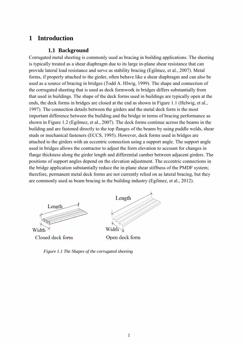
Corrugated metal sheeting is commonly used as bracing in building applications. The sheeting is typically treated as a shear diaphragm due to its large in-plane shear resistance that can provide lateral load resistance and serve as stability bracing (Egilmez, et al., 2007). Metal forms, if properly attached to the girder, often behave like a shear diaphragm and can also be used as a source of bracing in bridges (Todd A. Hlwig, 1999). The shape and connection of the corrugated sheeting that is used as deck formwork in bridges differs substantially from that used in buildings. The shape of the deck forms used in buildings are typically open at the ends, the deck forms in bridges are closed at the end as shown in Figure 1.1 (Helwig, et al., 1997). The connection details between the girders and the metal deck form is the most important difference between the building and the bridge in terms of bracing performance as shown in Figure 1.2 (Egilmez, et al., 2007). The deck forms continue across the beams in the building and are fastened directly to the top flanges of the beams by using puddle welds, shear studs or mechanical fasteners (ECCS, 1995). However, deck forms used in bridges are attached to the girders with an eccentric connection using a support angle. The support angle used in bridges allows the contractor to adjust the form elevation to account for changes in flange thickness along the girder length and differential camber between adjacent girders. The positions of support angles depend on the elevation adjustment. The eccentric connections in the bridge application substantially reduce the in-plane shear stiffness of the PMDF system; therefore, permanent metal deck forms are not currently relied on as lateral bracing, but they are commonly used as beam bracing in the building industry (Egilmez, et al., 2012).
Figure 1.1 The Shapes of the corrugated sheeting

2
Figure 1.2 Connection between the girders and metal deck form
The design of steel-concrete bridge girder must consider all loading stages. A critical loading for the composite bridge girder occurs during the placement of the concrete bridge deck, when the steel girder must carry the entire construction load. This construction load includes the weight of the steel girder, the formwork (including any Permanent Steel Bridge Deck Form), the fresh concrete, the finishing machine and all other equipment and personnel used in the placement of the concrete. During the concrete placement phase of construction, a small top flange of the girder lies in the positive bending moment regions. The small top flange, which is loaded in compression in the positive bending moment regions, makes the girder susceptible to lateral torsional buckling between the bridge cross frames or diaphragm as shown in Figure 1.3 (Egilmez, et al., 2007).
Figure 1.3 Buckled shapes of beams (Egilmez, et al., 2007)
Lateral torsional buckling must be resisted through either the use of cross frames and diaphragms or an increase in the size of the top flange of the girder. Permanent Steel Bridge Deck Forms are investigated for use as the bracing element to stabilize the top girder flange against lateral torsional buckling. For adequate stability bracing, the forms must possess sufficient stiffness and strength. For this reason, choosing a suitable Permanent Metal Deck Form in terms of shear stiffness is of great importance when the intended use is as a lateral bracing element. The PMDFs improve the lateral- torsional buckling capacity of the girders
3
they are fastened to since they behave as a shear diaphragm and restrain the warping deformation of the top flange during construction (Helwig & Yura, 2008).
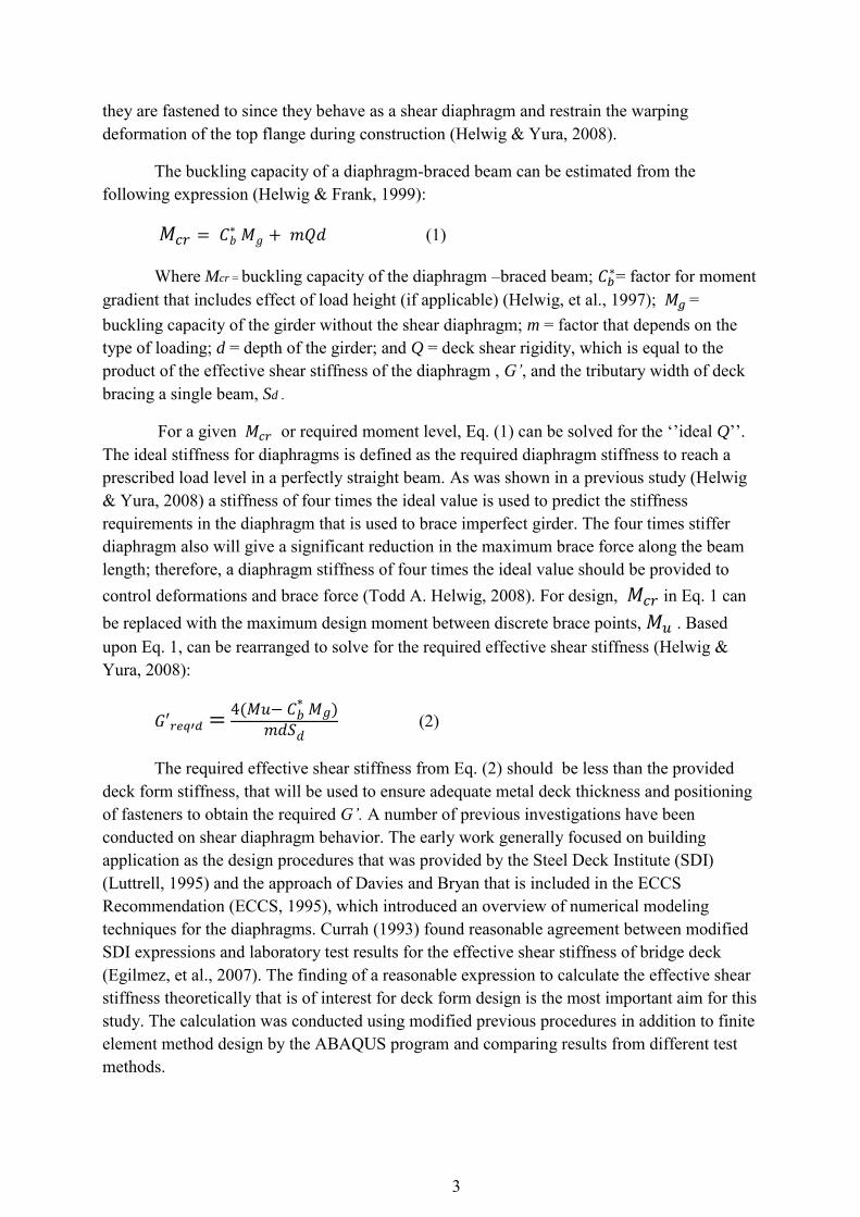
The buckling capacity of a diaphragm-braced beam can be estimated from the following expression (Helwig & Frank, 1999):
(1)
Where Mcr = buckling capacity of the diaphragm –braced beam; = factor for moment
gradient that includes effect of load height (if applicable) (Helwig, et al., 1997); = buckling capacity of the girder without the shear diaphragm; m = factor that depends on the type of loading; d = depth of the girder; and Q = deck shear rigidity, which is equal to the product of the effective shear stiffness of the diaphragm , G’, and the tributary width of deck bracing a single beam, Sd .
For a given or required moment level, Eq. (1) can be solved for the ‘’ideal Q’’. The ideal stiffness for diaphragms is defined as the required diaphragm stiffness to reach a prescribed load level in a perfectly straight beam. As was shown in a previous study (Helwig & Yura, 2008) a stiffness of four times the ideal value is used to predict the stiffness requirements in the diaphragm that is used to brace imperfect girder. The four times stiffer diaphragm also will give a significant reduction in the maximum brace force along the beam length; therefore, a diaphragm stiffness of four times the ideal value should be provided to control deformations and brace force (Todd A. Helwig, 2008). For design, in Eq. 1 can be replaced with the maximum design moment between discrete brace points, . Based upon Eq. 1, can be rearranged to solve for the required effective shear stiffness (Helwig & Yura, 2008):
(2)
The required effective shear stiffness from Eq. (2) should be less than the provided deck form stiffness, that will be used to ensure adequate metal deck thickness and positioning of fasteners to obtain the required G’. A number of previous investigations have been conducted on shear diaphragm behavior. The early work generally focused on building application as the design procedures that was provided by the Steel Deck Institute (SDI) (Luttrell, 1995) and the approach of Davies and Bryan that is included in the ECCS Recommendation (ECCS, 1995), which introduced an overview of numerical modeling techniques for the diaphragms. Currah (1993) found reasonable agreement between modified SDI expressions and laboratory test results for the effective shear stiffness of bridge deck (Egilmez, et al., 2007). The finding of a reasonable expression to calculate the effective shear stiffness theoretically that is of interest for deck form design is the most important aim for this study. The calculation was conducted using modified previous procedures in addition to finite element method design by the ABAQUS program and comparing results from different test methods.

4
The shear diaphragm typically consists of corrugated sheets fastened to the top flange of the beams. The distribution of the fasteners forces across the panel width provides an indication of the variation in the brace force along the member to be braced. The fasteners force model provides a rational approach that can be used to evaluate the brace strength requirements for diaphragm fasteners (Helwig & Yura, 2008). Todd and Yura (2008) developed a model for determining the stability induced fastener forces and equations for the resulting fastener forces were presented as a function of the number of fasteners. Currently in this study, the relation between applied load and fastener forces that is of interest for fasteners design was derived as well as the effect of seam fasteners, sheet thickness and the length of the span on this relation was determined using finite element method by the ABAQUS program.
1.2 Objective of study
1.2.1 Calculation of the shear stiffness of metal decks using European regulation
The Calculation of the effective shear stiffness (G’ ) of Permanent Metal Deck Form (PMDF) that acts as a shear diaphragm in bridge application is conducted using the amendment European regulations’ procedure and the modified SDI Manual’s procedure and compare these stiffnesses with the results of shear stiffness from finite element method. The investigation includes finding G’ for PMDF that is used in the building application and that which is used in the bridge application to compare the results to determine the difference in G’. Both closed end and open end profiles are examined to find the effect of the profile section type of sheet end on G’. Two theoretical methods are used to determine the value of G’ for the same model: the definition of the Steel Deck Institute Diaphragm Design Manual SDI (Second Edition) and using the European recommendation (ECCS Publication). The results of PMDF shear stiffness in bridge system that are obtained from using SDI Manual and ECCS recommendations are compared with the shear stiffness values that were computed from finite element method (FEM) using the ABAQUS program. The purpose of this comparison is to determine if these design formulations can be used to provide an adequate estimation of stiffness for PMDF. Many parameters are investigated, like thickness of sheet, length of span, number of the side lap fasteners and panel sheeting width.
1.2.2 The numerical investigation of fasteners forces between metal decks and beams
The study also includes numerical (using ABAQUS) investigation of forces that act on the shear fasteners that are used to fasten the sheets to the top flange of beams. The distribution of the fasteners forces across panel width and the effect of the parameters like the span between beams and the sheets thickness on the magnitude of this force are also investigated.

5
2 Permanent Metal Deck Forms (PMDFs)
2.1 PMDFs applications
2.1.1 Building application
Light gauge metal decking is commonly used in the building industries (Figure 2.1). In addition to supporting the wet concrete and other loads during construction, metal formwork is used to improve the lateral-torsional buckling capacity of the beams they are fastened to, as long as metal decks behave as a shear diaphragm and restrain the warping deformation of the top flange. Metal formwork in the building industry is relied on for stability bracing. (Todd helwig, 2005)
Figure 2.1 Metal formwork in the building application (Todd helwig, 2005)
2.1.2 Bridge system
The PMDFs are commonly utilized to support the fresh concrete deck during construction. However metal deck forms in the building industry are typically relied on for stability bracing, PMDFs are not permitted for bracing in the bridges industry. One of the reasons the forms are not relied on for bracing in the bridge applications is using of support angles which are used to support the deck form and to adjust the form elevation to account for changes in flange thickness and differential camber between adjacent girders (Figure 2.2). The eccentric connections between sheets and support angle lead to reducing in the in-plane stiffness of the PMDF system. The small stiffness of the connection usually dominates the stiffness of the PMDF system, as indicated in the following (Egilmez, et al., 2012) :
(3)
Where the inverse of the total system stiffness ( ) is equal to the sum of the inverse of the component stiffnessses ( = stiffness of the deck form and =stiffness of the connection). The system stiffness is smaller than component ( or ). .

6
The improving of the connection stiffness and improving the stiffness of eccentrically connected metal deck has been developed in previous study like (Helwig & Yura, 2008) . Therefore; the using of stiff connection (support angles) lead to make that the permanent deck form is dominating on the stiffness of system against the lateral deformation, thereby good estimation for PMDF shear stiffness (G’) leading to stiff system.
Figure 2.2 Deck form in the bridge application (Egilmez, et al., 2012)
2.2 Stay-in-place metal decks as shear diaphragm in bridge system
Many of the early investigations about the behavior of deck form as a shear diaphragm were focused on building application. These investigations provide a good background on shear diaphragm behavior. A good summary of the current diaphragm design procedures is provided by the Steel Deck Institute (SDI) (Luttrell, 1995)
A number of studies have been conducted to improved understanding of the stability bracing behavior of shear diaphragms for beams and focusing on the shear behavior of the bridge deck form such as Currah (1993) and Helwig & Frank (1999). Because of the large in-plane shear strength and stiffness, metal deck forms are often modeled as a diaphragm to restrain the lateral movement of the top flange. The buckling deformations that may occur in a steel girder with metal deck forms fastened to the top flange. Buckling located between the ends of beams or between the cross-frame locations in the twin-girder system as shown in (Figure 2.3). Lateral torsional buckling is a failure mode that the beams are subjected to and that includes both lateral and torsional deformation. The bracing in twin-girder (most common in Sweden) system include the restraining either twist of the girder cross section or lateral deformation of the compression flange. The shear stiffness and shear strength characteristics

7
of the deck form should be big enough in order to prevent too large lateral deformation bracing. (Egilmez, et al., 2007)
Figure 2.3 Bucked shape of beams and PMDF as Beam Bracing (Todd helwig, 2005)
2.3 Effective shear stiffness G’
Shear stiffness is expressing the ratio between the force per unit area (shearing stress) that causes a laterally deformation and the shear (shearing strain) that is produced by this force. The deck panel shear stiffness is of great importance when the intended use is as a lateral bracing element. Shear stiffness is significant in evaluating how forces are transferred, through the deck panel, from one bridge girder to the other. This force transfer is important to the stability of the deck-girder system (Currah, 1993). The shear modulus of corrugated sheeting is generally not linear function of the material thickness, therefore an effective shear stiffness G’ is not a function of the material thickness (Egilmez, et al., 2007). For the building application the effective shear stiffness can be determined using the design tables in the SDI Diaphragm Design Manual (Luttrell, 1995) or the European Recommendation, ECCS Publication, (ECCS, 1995).
The shear stiffness of deck form can also be measured experimentally using a cantilever shear test such as (Figure 2.4). The applied load is amplified because of the geometry of the testing and the testing frame geometry must be considered in evaluating the effective shear stiffness. The effective shear stiffness as given in Eq. (4) is the ratio of effective shear stress, as a result of the lateral force, that laterally deforms the deck to the displacement per unit sample length (effective shear strain) (Egilmez, et al., 2007).
(4)
Where

8
= Effective shear stress =
(5)
γ = Effective shear strain (Angular deformation) =
(6)
= Effective shear reaction (7)
(8)
Figure 2.4 Cantilever shear frame (Egilmez, et al., 2007)
The main differences between calculations of G’ for profiled sheeting that used in the building and this one which is used as a deck form in the bridge are:
i. Using of purlins as an intermediate member in the building system which the fasteners used to connect the sheet to the purlins. The flexibility of these fasteners should be considered in the calculation of G’ in the building applications. In addition the deck panels in some of the building applications are supported on all four side while the bridge decking provides support from the girder flange on only two sides. (Todd helwig, 2005)
ii. In building applications, the profiled sheeting is connected directly to the flange by welding shear studs through the forms or by using puddle welds or mechanical fasteners. In these applications, the panels are often continuous over the top of the beam and these direct connections between the main members and PMDF efficiently take advantage of the large stiffness of the deck form. In bridge applications, the bridge deck form sheets are connected by fasteners to support angles which are attached to the flange of the beam. These support angles help the contractor to adjust the form elevation to account for change in flange thickness and the variations in girder camber along the length of the bridge. Although the convenience that is provided by

9
the angles in the managing constructability issues, the eccentricities often countered will substantially reduce the stiffness of a deck form system. The rotation angle between the deck sheet and the flange depends on the flexibility of the support angle, in this study the consideration that the rotation angle is zero because of the direct connection between the deck form and the top flange of beam. In this case the attachment without eccentricity. (Egilmez, et al., 2007)
iii. The ends of the corrugation of each sheet that is used in bridge applications are closed to provide a seal for the concrete. These closed ends tend to stiffen the forms compared to building forms where the end of sheets are open, in which the stiffness is reduced due to warping deformations of the corrugations. (Todd helwig, 2005) PP3-7
Figure 2.5 and Figure 2.6 shows the open end sheet and closed end sheet respectively where: a = sheet width
b = sheet length (span)
d= pitch
t= thickness (gage)
h= depth
w= cover width

10
Figure 2.5Open end sheets
Figure 2.6 Closed end sheets

11
3 Current methods to calculate metal deck diaphragm’s rigidity The calculation of the effective shear stiffness theoretically is conducted by two methods, one is utilizing the SDI Manual and another one using the approach of Bryan and Davies given in the ECCS recommendation NO. 088. For both, the design equations have been modified to be useable in bridge application because of the formulations in these manuals are based on building application. Currah (1990) found reasonable agreement between modified SDI expressions and laboratory test results for the effective shear stiffness and shear strength of bridge decking, this modified expressions have been used in this study to calculate G’ in bridge system.
Panel sheeting types in this study
Many types of panel sheeting are investigated to determine the effect of the parameters changing on the effective shear stiffness. Three common thicknesses for each type of panel sheeting are used to compute the effective shear stiffness. Thicknesses are 1.204mm, 0.909mm and 0.749mm. The types of panel sheeting that are tabulated below (Table 3.1) are used for both open end and closed end profile section. The investigation included two type of width (Wd) of panel 2.4m and 4.8m, where these represent parts of the distance between the ends of beams or between cross frames in bridge application along the girders. Different spans (Ld) were examined to study the effect of the length of span on the magnitude of G’.
Table 3.1 Panel sheeting types for both open-and closed- end profile section
Panel type Case No. Wd(mm) X Ld (mm)
Type A A-W2.4-L1.2 2400 X 1200 A-W2.4-2.4 2400 X 2400 A-W2.4-L3.6 2400 X 3600 A-W2.4-L4.8 2400 X 4800 A-W2.4-L6 2400 X 6000 A-W2.4-L7.2 2400 X 7200
Type B B-W4.8-L1.2 4800 X 1200 B-W4.8-L2.4 4800 X 2400 B-W4.8-L3.6 4800 X 3600 B-W4.8-L4.8 4800 X 4800 B-W4.8-L6 4800 X 6000 B-W4.8-L7.2 4800 X 7200

12
3.1 SDI Manual
Steel Deck Institute developed a design manual to provide estimation for the shear stiffness and shear strength of a particular deck diaphragm. The physical properties of the deck sheets and their fasteners layout are essential in this estimation. The variety of deck types that have been tested by Steel Deck Institute commonly used in the building industry and the results enable the designer to evaluate the shear capacity of a particular deck without the expense of laboratory testing.
3.1.1 Calculation of G’ in Bridge application
The assumptions that are made in order to apply the SDI equations to the bridge deck are:
a) Screw No.12 and No.14 Buildex TEKS are presented in the SDI Manual. The values of screw flexibility for the heavier substrate material Sf and for stitch screw specimens Ss were calculated using SDI Manual equations 4.5.1-1 and 4.5.1-2.
b) Radius corners and formed deck stiffeners in the deck profile were neglected and the warping constant D-values developed using the equations presented in Appendix IV of the SDI Manual. Deck profile dimensions used in the equations and these straight line approximations are shown in Figure3.1
c) The assumption to calculate warping constant Dn in the SDI Manual was based on the open ended corrugated deck panels. Deck profile used in this study actually closed in the deck- ends which should add some resistance to warping at the corrugation ends. In order to determine the difference in the shear stiffness, two SDI stiffness value are presented. Calculation of stiffness to closed end was computed by removing the Dn term from Equation 5.8-1 while the stiffness for open ended was computed using the SDI manual Dn values. (Currah, 1993)
Figure 3.1 Deck profile dimensions used in manual equations (Luttrell, 1995, pp. 3-1)

13
Diaphragm stiffness
The shear stiffness of a corrugated diaphragm according to SDI Manual may be measured by testing an assembly such as that in Figure 3.2. As the load P increases, the shear deflection ∆ is noted.
The average shear strain in the system is
while the average shear stress within
the diaphragm is
, which t is plate thickness. The classic definition for shear modulus
is:
=
(9)
Since the diaphragm is not a thick flat plate, its stiffness is not linear with the thickness t. Effective shear stiffness G’ could be expressed as:
(10)
Factors affecting stiffness
As forces P are applied parallel to the edges, as shown in Figure 3.3, shear displacements ensue and the total shear deflection for all corrugations is . The end closure prevents changes in the cell geometry and the cell is actually pure shear around its girth. When the effect of the closed end is removed, relaxation would occur through warping and the sum of all warping relaxations is as shown in Figure 3.3. Then G’ could be expressed as:
Figure 3.2 Layout of diaphragm (Luttrell, 1995)

14
(11)
The discrete connections at panel side laps (side laps fasteners) further increase the deflection relaxation under load by an amount of such that:
(12)
Figure 3.3 Shear distortions
All three terms of involve E, t, L and P and lead to a modified form as is defined by equation 3.3-3 of the Steel Deck Institute Diaphragm Design Manual (second Edition).
(
) (13)
Where: E = Modulus of elasticity = 210 GPa =Poisson’s ratio = 0.3 = warping constant C = connector slip parameter d = Corrugation pitch t = Base metal thickness =1.0 for simple span deck sheets
The slip coefficient C depends on the shear forces directly at the side laps which, in turn, depend on the number and location of fasteners in a panel, thickness of the profile that

15
has been selected, and length of panel (span) (Luttrell, 1995) . Equation 3.3-1 of the Second Edition of the SDI Manual represents simplified equation for the connection slip parameter. This is equation based on the assumption that the numbers of intermediate edge connectors (ne) are equal to the number of side lap fasteners (ns), this equation is more useable in the building applications. For bridge systems there are no intermediate edge connectors, that is means (ne ) does not equal (ns) and the more exact equation will be used for C. this equation can be found in the Page 28 of the Steel Deck Institute Diaphragm Design Manual (First edition) as below (Eq.14): (Currah, 1993)
(14)
∑ (15) (Appendix1)
where: L = Panel lenfth ( deck sheet span length
a = Overall diaphragm panel width
nsh = Number of individual deck sheets in panel
np = Number of purlins ( zero for bridge application)
ns = Number of side lap fasteners, to attach the adjacent sheets together, per seam
Wsh = Individual deck sheet width
= 0, for no purlins
t = thickness of sheet
ne = Number of edge connectors ( zero for all models)
Xe = Distance from individual deck sheet centerline to any fastener in a deck sheet at the end fasteners
Sf = Structural connector, which connecting sheets to beams, flexibility.
Ss = Side lap connector, which connecting adjacent panels, flexibility.
Sf and Ss are defined respectively in the second edition of the SDI Manual by equations 4.5.1-1 and 4.5.1-2 respectively. See AppendixA.1
The warping constant Dn used to measure the warping relaxation at the ends of the diaphragm panels. The warping depends on the span and thickness of the profile. Obviously the warping is smaller with frequently spaced end connections. The warping constant is defined in the second edition of the SDI Manual as (Eq.16):
(16) (SDI Manual, Second Edition, 3.3-2)

16
The D-value is developed in appendix IV of SDI Manual and depends on the distribution of end fasteners. In this study DW1 is the selected value to be D-value which it established for fasteners in each trough, the Appendix A.1 shows the example of calculation. The results of calculation of G’ for both open ended and closed end deck form with consideration different span length and three sheet thicknesses are tabulated below from Table3.2 and Table3.3.
Table 3.2 Effective shear stiffness G’ values (KN/m) using SDI Manual for open-and closed- end
deck form Type A for three different sheet thicknesses.
Case No. Deck
span(m)
No. of
Side lap
fasteners
G’, SDI (KN/m)
Panel width (Wd) = 2400mm
t* =1.204 t = 0.909 t = 0.749
Open
end
Closed
end
Open
end
Closed
end
Open
end
Closed
end
A-W2.4-L1.2 1.2 3 2356 20098 1249 16593 789 14486
A-W2.4-L2.4 2.4 5 3852 13843 2192 11611 1432 10254
A-W2.4-L3.6 3.6 8 4704 11403 2852 9625 1931 8539
A-W2.4-L4.8 4.8 11 5111 9805 3275 8310 2295 7395
A-W2.4-L6 6 13 5244 8640 3489 7214 2527 6437
A-W2.4-L7.2 7.2 16 5218 7741 3609 6505 2686 5813
* t = sheet thickness (mm)
Table 3.3 Effective shear stiffness G' for open-and closed- end deck form Type B and for three
different thicknesses
Case No. Deck
span(m)
No. of
Side lap
fasteners
G’, SDI (KN/m)
Panel width (Wd) = 4800mm
t* =1.204 t = 0.909 t = 0.749
Open
end
Closed
end
Open
end
Closed
end
Open
end
Closed
end
B-W4.8-L1.2 1.2 3 2373 21456 1158 17654 790 15376
B-W4.8-L2.4 2.4 5 3973 15542 2081 12980 1453 11427
B-W4.8-L3.6 3.6 8 5030 13535 2801 11362 2000 10040
B-W4.8-L4.8 4.8 11 5690 12185 3342 10264 2437 9093
B-W4.8-L6 6 13 5986 10856 3698 9176 2755 8150
B-W4.8-L7.2 7.2 16 6195 10105 3978 8558 3015 7612
*t= sheet thickness (mm)

17
3.1.2 Calculations of G’ in building application
Application of SDI equation in the SDI Manual is as straightforward to compute SDI stiffness of the open ended deck forms in the building system. The simplified equation 3.3-1 of the Second Edition of the SDI Manual is used to find connector slip parameters (C). This simplified equation is based on the assumption that the numbers of intermediate edge connectors (ne) are equal to the number of side lap fasteners (ns). The simplified equation to find C is useable in the building application and is reproduced below (Eq.17): (Luttrell, 1995)
(17)
Where: W = Panel width
The effective shear stiffness (G’) has been calculated using standard tables to find parameters K1 and K2. This tables based on the total deck span (L) equal to three span condition with L= 3 Lv where Lv is the span between purlins. The effective shear stiffness equation represented as below (Eq.18):
G’ =
⁄ (18)
Where : C = 3.K.Lv
K1 values in the tables are based on the assumption that Wd (panel width) equal to 609mm. This value should be divided by 4 to be suitable to the panel width 2400mm or 8 for panel width 4800mm (according to the investigated models in this study).The table that was used in the calculations and an example of calculations are shown in Appendix B.
Table3.4 shown the results of calculation of G’ for open deck form as used in building application using SDI Manual standard tables, different span lengths is investigated, Panel that used is Type A and the thickness of sheet is 1.204mm
Table 3.4 Effective shear stiffness G'(KN/m) for open ended deck form Type A (Building
application) using SDI Manual standard tables, t= 1.204mm
Case No. Deck span(m)
No. of Side lap fasteners
G’ , SDI (KN/m) Panel width=2400mm
A-W2.4-L1.2 1.2 3 3176 A-W2.4-2.4 2.4 5 5815 A-W2.4-L3.6 3.6 8 6797 A-W2.4-L4.8 4.8 11 7930 A-W2.4-L6 6 13 8784 A-W2.4-L7.2 7.2 16 9444
18
3.2 ECCS Recommendation No.088
Shear diaphragm or diaphragm based on definition of Bryan and Davies is a general term for one or more shear panels or that area of sheeting which resists in-plane displacement by shear in which in-plane shear in the sheeting is taken into account in design (ECCS, 1995). Table 5.5 R.30 in the ECCS Publication was used to find the components of shear flexibility with consideration of cantilevered diaphragm and sheeting spanning perpendicular to the length of diaphragms (Figure 3.5).
3.2.1 Calculation of G’ in Bridge system
The total shear flexibility C of deck forms that used in the bridge applications, such panel as shown in Figure 3.2 will be described as the summation of components of the various factors involved. The main components considered are due to: shear deformation C1 distortion of corrugation profile C2, and local deformation of sheet at the beam and seam connections C3, C4. For bridge system consideration the beams are rigid that means the flexibility due to axial deformation of beams C3 could be taken as equal to zero. There are no purlins in the bridge applications so the flexibility due to fasteners deformation in the sheet to perpendicular member fastener can be neglected. The equations are based on:
b= depth of the shear panel. Dimension of shear panel in direction parallel to the corrugations (mm).
a= width of the shear panel. Dimension of shear panel in a direction perpendicular to the corrugations (mm).
d= Pitch of corrugations (mm).
h= Height of sheeting profile (mm).
E= Modulus of elasticity (KN/mm2).
K1 = Sheeting constants for every corrugation fastened according to (ECCS, 1995) Table 5.6-C30
Ss = Flexibility of seam (side lap) fasteners = 0.15 .10-3 m/KN
Sp = flexibility of shear fasteners (connection with the beams) = 0.15.10-3 m/KN
Ss and Sp values according to (kathage, et al., 2013) Table1- p.108
The following properties of steel may be assumed in design:
- Modulus of elasticity E = 210 KN/mm2
- Shear modulus G =81 KN/mm2
- Poisson's ratio ν = 0.3
- Density ᵨ = 7850 kg/m3

19
Figure 3.4 Deck form in bridge application, type A
The components of the total shear flexibility are (ECCS, 1995):
Flexibility due to shear deformation of sheet C1
(b/a) (19)
Where: α = [1+(2h/d)] (20)
The flexibility due to shear deformation according to SDI Manual and C1 according to ECCS Recommendation differ by just multiplication with the aspect ratio a/b of the overall dimensions of the shear diaphragm. Therefore C1 can be written without this ratio to adjust this flexibility according to ECCS Recommendation in line with SDI Manual. The expression for C1 applies for b/d ≥ 10 according to ECCS Recommendations, so the panel with span equal to 1200mm was neglected in this investigation.
Flexibility due to bending of corrugation profile ( profile distortion) C2
This flexibility will be dependent on the manner of attachment of the sheeting to the beam and on the geometry of the end of the profiled sheet that will twist out of shape by its own shear flow (Figure 3.3). When the profiled sheeting is closed end, so this flexibility could be taken like zero where the sheet is restrained against end warping. Bryan and Davies presented an equation for shear flexibility due to distortion at the open end sheet profile, the form is:
(b/a) (21)

20
C2 can be written without the ratio a/b to adjust ECCS Recommendation in line with SDI Manual
Figure 3.5 warping in the end
Flexibility due to local deformation at sheet-beams fasteners C3
The sheeting should be attached with fasteners which carry shear forces without reliance on friction or bending of the fasteners themselves. The fasteners should be of a type which will not work loose in service and which will neither pullout nor fail in shear before causing tearing of the sheeting. Examples of suitable fasteners are self-tapping or self-drilling screws, shot pins (cartridge fired or air driven), bolts or welding. Hook bolts, clips or other fasteners which transmit shear forces by friction are not suitable (ECCS, 1995). The equation that is found in ECCS to find the flexibility to sheet-beams fasteners is unusable in bridge system because of this equation depends on the number of purlins where there are no purlins in the bridge application. The expression that was found by (Wright & Hossain, 1997) can be used to find the flexibility of sheet-beam fasteners. In this study the part of this expression which is dealing with the sheet-beams fastener was used as below (Eq.22):
(22)
Where: = the spacing of sheet-beam fasteners
Sp = Table 5.1 ECCS Publication
Multiplication by b/a ratio was considered in the application of this expression.
Flexibility due to crimping at seam fasteners C4
The seams between adjacent sheets should be fastened by fasteners of a type which will not work loose in service and which will neither pullout nor fail in shear before causing tearing of the sheeting. Examples of suitable fasteners are self-drilling screws, monel metal or stainless steel blind rivets, bolts or welding. Aluminium blind rivets are not generally suitable (ECCS, 1995) R13.

21
Fastener slip is the movements at a fastener in the plane of the sheeting per unit shear force per fastener. The crimping in the seam fasteners results additional flexibility. The flexibility due to side lap fasteners according to SDI Manual and C4 differ by multiplication with the aspect ratio b/a, therefore the equation for C4 multiplied with b/a in the calculations to adjust the ECCS Recommendation in line with SDI Manual.
(23)
The total of flexibility is:
C = C1 + C2 + C3 + C4 (24)
Where the shear stiffness will be:
G’ =
(25)
Appendix 3- shown example of computation of G’ according to ECCS Recommendation
Effective shear stiffness values for deck form with open end and closed end sheets in bridge application using ECCS Recommendation are listed in Table3.5 and Table3.6. An example of calculations and equations’ table are shown in Appendix A.2. In this investigation, three types of sheet thicknesses were examined, 1.204mm, 0.909mm and 0.749mm. The calculations included pane Type A where overall panel width is 2400mm and Type B where the panel width is 4800mm to determine the effect of panel width on the value of shear stiffness. For each panel type the lengths of span between beams were varied from 1.2m to 7m.
Table 3.5 Effective shear stiffness G' according to ECCS recommendations for bridge deck
form, Type A, open-and closed-end sheet profile.
Case No. Deck
span(m)
No. of
Side lap
fasteners
G’, ECCS (KN/m)
Panel width (Wd) = 2400mm
t* =1.204 t = 0.909 t = 0.749
Open
end
Closed
end
Open
end
Closed
end
Open
end
Closed
end
A-W2.4-2.4 2.4 5 1856 7509 1031 7191 675 6942
A-W2.4-L3.6 3.6 8 2435 7131 1429 6843 959 6618
A-W2.4-L4.8 4.8 11 2831 6651 1750 6400 1204 6202
A-W2.4-L6 6 13 3030 5961 1977 5758 1401 5598
A-W2.4-L7.2 7.2 16 3189 5609 2169 5429 1574 5286
*t= sheet thickness (mm)

22
Table 3.6 Effective shear stiffness G'(KN/m) according to ECCS recommendations for open-and
closed-end deck form Type B, Bridge application
Case No. Deck
span(m)
No. of
Side lap
fasteners
G’, ECCS (KN/m)
Panel width (Wd) = 4800mm
t* =1.204 t = 0.909 t = 0.749
Open
end
Closed
end
Open
end
Closed
end
Open
end
Closed
end
B-W4.8-L2.4 2.4 5 2106 14465 1104 13327 705 12497
B-W4.8-L3.6 3.6 8 2941 14390 1589 13263 1028 9216
B-W4.8-L4.8 4.8 11 3646 14008 2030 12938 1331 9129
B-W4.8-L6 6 13 4180 13001 2409 12074 1605 8573
B-W4.8-L7.2 7.2 16 4667 12657 2764 11777 1866 8473
*t= sheet thickness (mm)
Table 3.7 and Table 3.8 contain the values of SDI stiffnesses and ECCS stiffnesses for three of the decks cases to compare the results. Table 3.7 for open ends metal decks and Table 3.8 for closed ends metal deck.
Table 3.7 Comparison of SDI stiffnesses and ECCS stiffnesses for open ends metal decks,
panel Type A
Case No.
Deck
span
(m)
t*
(mm)
G’, SDI
(KN/m)
G’, ECCS
(KN/m)
G’SDI / G’ECCS
A-W2.4-L2.4
2.4 1.204 3852 1856 2
0.909 2192 1031 2.1
0.749 1432 675 2.1
A-W2.4-L4.8
4.8 1.204 5111 2831 1.8
0.909 3275 1752 1.87
0.749 2295 1204 1.9
A-W2.4-L7.2 7.2 1.204 5218 3189 1.62
0.909 3609 2169 1.6
0.749 2686 1574 1.7
*t= sheet thickness

23
Table 3.8 Comparison of SDI stiffnesses and ECCS stiffnesses for closed ends metal decks,
panel Type A
Case No.
Deck
span
(m)
t*
(mm)
G’, SDI
(KN/m)
G’, ECCS
(KN/m)
G’SDI/
G’ECCS
A-W2.4-L2.4
2.4 1.204 13843 7509 1.8
0.909 11611 7191 1.6
0.749 10254 6942 1.5 A-W2.4-L4.8
4.8 1.204 9805 6651 1.5
0.909 8310 6400 1.3
0.749 7395 6202 1.2 A-W2.4-L7.2 7.2 1.204 7743 5609 1.4
0.909 6505 5429 1.2
0.749 5813 5286 1.1
*t= sheet thickness
3.2.2 Building application
With accordance to Bryan and Davies approach the total shear flexibility C of profiled deck form is designed to be applicable in the building system as shown in Figure3.6
Figure 3.6 sheeting form in building application according to ECCS Recommendation (ECCS, 1995)
The total shear flexibility C of deck forms that are used in the building applications will be described as the summation of components of the various factors involved. The main components considered are due to: shear deformation C1, distortion of corrugation profile C2, flexibility due to shear fasteners C3, flexibility due to sheet to perpendicular (purlins) fasteners C4 and flexibility due to seam connections C5. In this study, an assumption that the
24
beams are rigid was considered, so the flexibility due to axial deformation of beams could be taken as equal to zero.
The same decks that are used in the bridge application would be used to calculate the shear stiffness of deck form in the building application. Purlins which used as perpendicular member to sheets and the fasteners flexibility of sheet to these purlins would be considered in calculation. The connection to edge members it would be considered as four sides fastened to calculate shear flexibility due to these connections.
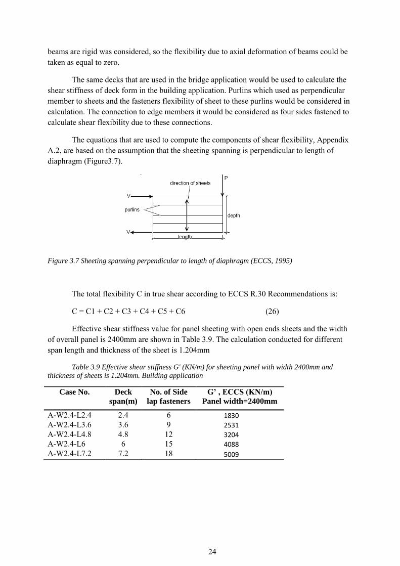
The equations that are used to compute the components of shear flexibility, Appendix A.2, are based on the assumption that the sheeting spanning is perpendicular to length of diaphragm (Figure3.7).
Figure 3.7 Sheeting spanning perpendicular to length of diaphragm (ECCS, 1995)
The total flexibility C in true shear according to ECCS R.30 Recommendations is:
C = C1 + C2 + C3 + C4 + C5 + C6 (26)
Effective shear stiffness value for panel sheeting with open ends sheets and the width of overall panel is 2400mm are shown in Table 3.9. The calculation conducted for different span length and thickness of the sheet is 1.204mm
Table 3.9 Effective shear stiffness G' (KN/m) for sheeting panel with width 2400mm and
thickness of sheets is 1.204mm. Building application
Case No. Deck
span(m)
No. of Side
lap fasteners
G’ , ECCS (KN/m)
Panel width=2400mm
A-W2.4-L2.4 2.4 6 1830
A-W2.4-L3.6 3.6 9 2531
A-W2.4-L4.8 4.8 12 3204 A-W2.4-L6 6 15 4088
A-W2.4-L7.2 7.2 18 5009

25
3.3 Finite Element Modeling of metal decks using ABAQUS
Two type of permanent metal deck form were used to investigate the effective shear stiffness of the PMDFs in bridge system. First type is open ended PMDF and the second one is closed end PMDF. This investigation based on the creation of two models for each type that have been used to analysis. One model was used for plate (beam) length, width of panel sheeting, 2.4m and another one was used for plate length 4.8m. Each plate length is represented the length of the girder from support point of the cross frame to the point where the maximum lateral -torsional buckling in the middle of span between two bracing cross frames in the bridge application as shown in Figure 3.8 below. Spans between girders for both models are 2.4, 4.8 and 7.2m and the thicknesses of the profiled sheets that were used as shear diaphragm are 1.204mm, 0.909mm and 0.749mm.
Both models have been used to study the influence of shear diaphragm span and the variations in thickness of the profiled sheets on the effective shear stiffness. The study is presented also the effect of the distance between the cross bracing and how this improves the shear stiffness of the profile sheets.
Figure 3.8 Buckling of girders with cross frame bracing
3.3.1 Metal decks considered in FEM study
The models symbolize parts of the bridge, one part containing four profiled sheets and one containing eight profiled sheets all as a shell elements. The models are contained parts of the underlying top flanges of the girder as shell elements. The material properties of these elements correspond with the properties of the shell elements of the sheeting, but compared to the elements of the sheeting they are much thicker. Therefore the elements of the top flange act as if they are indefinitely stiff.
Two analyses were performed, one which the length of the profiled sheeting between girders were varied and one which the thicknesses of the profiled sheets were changed. Materials properties are:
Modulus of elasticity ( E) = 210 GPa

26
Poisson’s ratio (ν) = 0.3
Dimensions of panel sheeting and the cases of tests are given in Table 3.10 and the thicknesses (t) that was used for each case are: 1.204 mm, 0.909 mm and 0.749 mm. The dimensions of the plate (top flange) are shown in Figure 3.9. A part of bridge with 2.4m length and the part that has 4.8m length (panel width Wd) are illustrated in Figure 3.10 and Figure3.11 respectively.
Table 3.10 Dimensions of panel sheeting cases for both open -and closed- ends sheets
Panel
type
Case No*. Wd (mm) X Ld (mm)
Type A A-W2.4-L2.4-t 2400 x 2400 A-W2.4-L4.8-t 2400 x 4800 A-W2.4-L7.2-t 2400 x 7200 Type B B-W4.8-L2.4-t 4800 x 2400 B-W4.8-L4.8-t 4800 x 4800 B-W4.8-L7.2-t 4800 x 7200
*thicknesses of sheet (t) =1.204mm, 0.909mm and 0.749mm
Dimensions of plates are shown in Table 3.11. The material properties of the plates are the same of metal decks.
Table 3.11 Dimenssions of plates
Plate type Dimensions
Depth(mm)xWidth(mm)x Thickness(mm)
Plate 240 x 40 2400 x 400 x 20 Plate 480 x 40 4800 x 400 x 20

27
Figure 3.10 Panel sheeting type A
Figure 3.11 Panel sheeting type B
Figure 3.9 Dimenssions of the plat
28
3.3.2 Profiled sheets panel attachment
In the analysis, the profiled sheets are attached to the top flange along the long sides of plate with fasteners in every trough. Fasteners type was beam, physical radius 6mm and all fasteners were constrained in all degree of freedom. Attachments lines for fasteners are placed 12.5 mm from the outer edges of top flange fasteners one node in each profiled –bottom of the profiled sheets to the surface of the top flange. In addition to this surface –to- surface contact is included between these parts. This contact is used to prevent an unrealistic movement of the profiled sheets where it slides through the top flange.
Side lap fasteners were created to attach two sheets together. The properties for side lap fasteners were the same to the fasteners in the top flange. Spacing between side laps fasteners were varied according to the span between top flanges. Spacing must be not more than 450mm according to European regulations.
3.3.3 Boundary conditions and load
Each one of top flanges (plates) are locking three of its degree of freedom along the long of the top flange, U2=UR1=UR3=0; fixed to move in the vertical direction and fixed to rotate around axes (X, Z). This boundary condition was used to improve relatively rigid beams. Each one of them top flanges is free to move in its axial direction and rotate around (Y) axis. One end of each top flanges is locking its degree of freedom in three directions (U1, U2, U3=0) to prevent its translation, another end is free to translate in its axial direction and force is applied to it in this direction. The application of force gives rise to similar action upon the structure as a lateral- torsional buckling during construction. Meshes of models were different and depending on the dimensions of the parts.
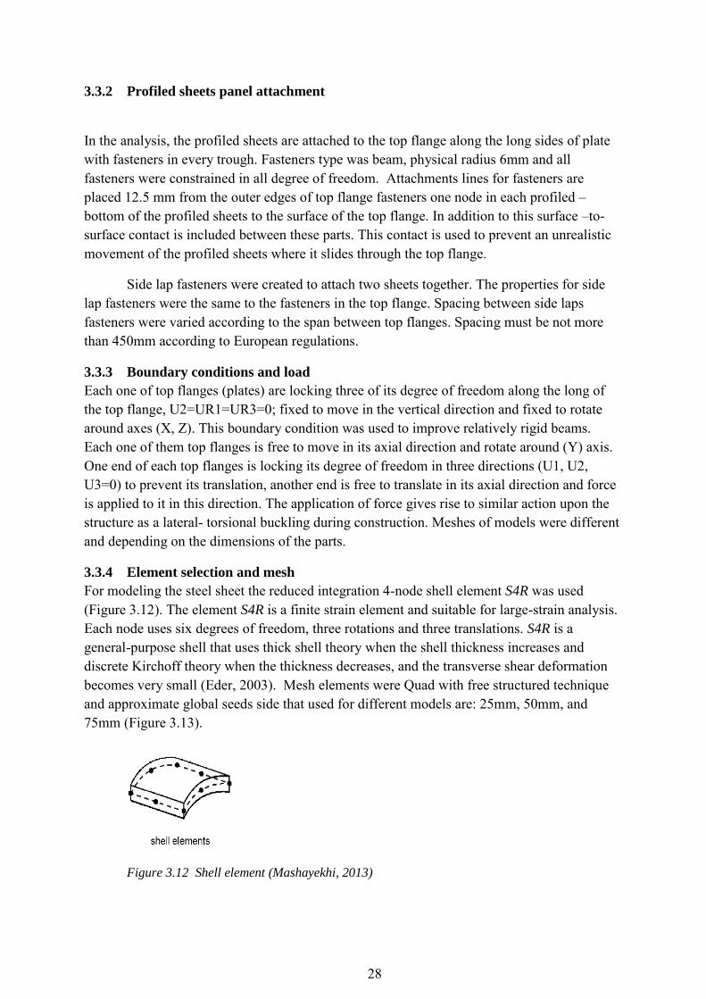
3.3.4 Element selection and mesh
For modeling the steel sheet the reduced integration 4-node shell element S4R was used (Figure 3.12). The element S4R is a finite strain element and suitable for large-strain analysis. Each node uses six degrees of freedom, three rotations and three translations. S4R is a general-purpose shell that uses thick shell theory when the shell thickness increases and discrete Kirchoff theory when the thickness decreases, and the transverse shear deformation becomes very small (Eder, 2003). Mesh elements were Quad with free structured technique and approximate global seeds side that used for different models are: 25mm, 50mm, and 75mm (Figure 3.13).
Figure 3.12 Shell element (Mashayekhi, 2013)

29
Figure 3.13 Meshing by ABAQUS
3.3.5 Profiled sheets thicknesses
The thickness of profiled sheets was altered. The analysis was performed for three different thicknesses: 1.204mm, 0.909mm, 0.747mm. The purpose of this variation in the thickness is to determine how the profiled sheet thickness affects the value of shear stiffness.
3.3.6 Finite element analysis
The degrees of freedom in the finite element analysis represent the primary variables that exist at the nodes of an element (Ottosen & Petersson, 1992). Displacements of the nodes in the transverse direction, in the same direction of the subjected load, are the main degree of freedom (U1) that investigated in this study. Another broad category that was used to classify elements was the mathematical formulation. Element formulation as finite –strain shells was used as a mathematical formulation to describe the behavior of an element. First order interpolation (four nodes element) with reduced integration as shown in Figure 3.14 , which the integration rule that is one order less than full integration rule, was used to calculate the stiffness and mass of an element at sampling points called integration points. An element’s number of nodes determines how the nodal degrees of freedom will be interpolated over the domain of the element.
Figure 3.14 S4R first - order interpolation (Documentation, 2012)
Structural element (shell) used for a more economical solution where requires far fewer elements than a comparable continuum (solid) element model. Algorithm options with

30
minimize the mesh transition was selected to reduce the mesh distortion. The Shell elements are approximate a three – dimensional continuum with a surface model that represent model in-plane deformations efficiently
3.3.7 Calculation of shear stiffness
The evaluation of the results focuses mainly on the effective shear stiffness (G’) of the shear diaphragm. Sheets were subjected to transverse shear forces (P) will show deflection (∆) in the transverse direction as shown in Figure3.12. The effective shear stiffness is defined as follows (Eq.24) according to (Egilmez, et al., 2007)
;
;
(27)
Where G’= effective shear stiffness (KN/m/rad); = effective shear stress of corrugation sheet (KN/m); ϒ= shear strain; P = shear load applied to the diaphragm; V =
effective shear reaction; = panel width; b= span /length of deck panel; and = shear deflection of the diaphragm which represents degree of freedom U1 in the ABAQUS results.
Shear test frame shown in the Figure3.15 according to (Egilmez, et al., 2007) consists of two relatively rigid beams are linked together at the ends. In the model, which was used in the ABAQUS, the point load (P) was applied at the tip of each beam to ensure transformation of shear load between these beams (Figure3.16). The amount of the effective shear stress that would appear along the edges of the panel depends on the dimensions of the panel, an example for the visualization of shear test results by ABAQUS is shown in Figure3.17.
Figure 3.15 Shear test model by experiment
Figure 3.16 Shear test model by ABAQUS

31
The Linear effects were considered in the analysis, linear relation between shear strain and shear stress was considered in the analysis as shown in Figure 3.18.
Figure 3.18 Shear stress vs. shear strain
Shear stiffness values that were computed using finite element method by ABAQUS are presented in Table3.12 and Table3.13 for open -and closed- end deck form. Three practical deck spans were used: 2.4m, 4.8m and 7.2m and two types of overall panel width. In addition, three types of sheet thicknesses were investigated to examine the effect of the sheet thickness on the value of the shear stiffness, the thicknesses that were investigated are: 1.204mm, 0.909mm and 0.749mm. An example of shear stiffness calculation is shown in Appendix A.3. Appendix C provides a sample of the input file that was used in the finite element analyses by ABAQUS.
Figure 3.17 Visualization of deformation test results by ABAQUS

32
Table 3.12 Effective shear stiffness results G' (KN/m) for open-and closed- end metal decks
type A using FEM.
Case No. Deck
span(m)
No. of
Side lap
fasteners
G’, FEM (KN/m)
Panel width (Wd) = 2400mm
t* =1.204 t = 0.909 t = 0.749
Open
end
Closed
end
Open
end
Closed
end
Open
end
Closed
end
A-W2.4-L2.4 2.4 5 3644 17879 1931 12922 1198 9893 A-W2.4-L4.8 4.8 11 5861 14135 3301 10810 2170 8822 A-W2.4-L7.2 7.2 16 5844 9628 3593 7376 2493 6083
*t=sheet thickness
Table 3.13 Effective shear stiffness results G' (KN/m) for open-and closed-end metal decks
type B using FEM.
Case No. Deck
span(m)
No. of
Side lap
fasteners
G’, FEM (KN/m)
Panel width (Wd) = 4800mm
t* =1.204 t = 0.909 t = 0.749
Open
end
Closed
end
Open
end
Closed
end
Open
end
Closed
end
B-W2.4-L2.4 2.4 5 3977 21656 2047 16201 1275 12758 B-W2.4-L4.8 4.8 11 6538 20126 3634 15574 2366 12761 B-W2.4-L7.2 7.2 16 7536 15979 4469 12558 3019 10494
*t= sheet thickness
33
4 Analysis and comparison of the effective shear stiffness results
4.1 Overview
This part of study contains an analysis of the investigation results that were presented in part 3 and will focus on the primary objectives of this study that are related to the effective shear stiffness of PMDF, namely:
1) Determination the effect of the open -and closed- end deck forms on the value of the effective shear stiffness.
2) A comparison of the shear stiffness value in building application to the shear stiffness value in bridge application.
3) An examination of the effect of the span length and sheet thickness on shear stiffness 4) An examination of the effect of the overall panel width on shear stiffness 5) A comparison of the results of shear stiffness that were computed using the procedures
of SDI Manual and the ECCS Recommendation to the results that were computed by ABAQUS.
6) Determination of procedures to allow an approximate determination of shear stiffness without experimental testing.
4.2 Analysis of results
The calculations in this study were conducted as an attempt to determine the difference in the shear stiffness between the PMDF that are open and closed at the end of the deck form. The results can also be used to determine the effect that the sheet thickness, deck span and panel width have on the shear stiffness of the diaphragm consisting of Permanent Metal Deck Form.
4.2.1 Analysis of SDI Manual results
The results of application of the SDI Manual equations to the permanent deck form show that the closed ended decks add more resistance to warping at the ends. This resistance provides more stiffness to the closed end deck form. The stiffness of the closed end profile deck forms with different thicknesses, as shown in Tables 4.1,4. 2, and 4.3, decrease significantly with the increasing of the deck span. This indicates that the increasing of the closed end deck length (deck span) leads to a decrease in the stiffness of the closed end deck form. Increasing the length of the span would provide more shear flexibility to the deck and increase the total shear deflection for all corrugations in spite of the fact that closed ends add some resistance to warping at the ends. In addition, the discrete connections at panel side laps further increase the relaxation for deflection under load where. The slip coefficient C for these connections depends directly on the length of span, the increase in the length of span leads to increase the slip coefficient C and as a result reduces the stiffness.
A comparison of the SDI’s computed open end deck stiffnesses to the closed end deck stiffnesses with panel width (Wd ) as 2.4m as shown in Tables 4.1,4.2, and 4.3, reveals that the stiffness of the open deck increases slightly with the increasing of the deck span. The open

34
ended deck would do not add resistance to warping at the corrugation end; however, the warping is less with frequently spaced end connections. The warping constant Dn measures the warping relaxation at the ends of the diaphragm panels. The warping relaxation is smaller when the length of the span is increased (Dn= D/12L SDI Manual). Therefore, the longer span provides less warping constant and less warping relaxation at the ends. Therefore, the decreasing of distortion at the ends contributes to the decreasing of the warping flexibility, which slightly adds stiffness to the deck form.
Table 4.1 Comparison of SDI Manual shear stiffness values of open profile deck to closed
profiled metal deck type A in bridge system, sheet thickness(t) 1.204mm.
Case No.
Deck
span(m)
G’ , SDI (KN/m)
Increases
in shear
stiffness
% Open end Closed end
A-W2.4-L1.2 1.2 2356 20098 88 A-W2.4-2.4 2.4 3852 13843 72 A-W2.4-L3.6 3.6 4704 11403 58 A-W2.4-L4.8 4.8 5111 9805 47 A-W2.4-L6 6 5244 8640 39 A-W2.4-L7.2 7.2 5218 7741 32
Table 4.2 Comparison of SDI Manual shear stiffness values of open profile deck to closed
profiled deck in bridge system, sheet thickness ( t) 0.909mm.
Case No.
Deck
span(m)
G’ , SDI (KN/m)
Increases
in shear
stiffness
% Open end Closed end
A-W2.4-L1.2 1.2 1249 16593 92 A-W2.4-2.4 2.4 2192 11611 81 A-W2.4-L3.6 3.6 2852 9625 70 A-W2.4-L4.8 4.8 3275 8310 60 A-W2.4-L6 6 3489 7214 51 A-W2.4-L7.2 7.2 3609 6505 44
Table 4.3 Comparison of SDI Manual shear stiffness values of open profile deck to closed
profiled deck in bridge system, sheet thickness (t) 0.749mm.
Case No.
Deck
span(m)
G’ , SDI (KN/m)
Increases
in shear
stiffness
% Open end Closed end
A-W2.4-L1.2 1.2 789 14486 94 A-W2.4-2.4 2.4 1432 10254 86 A-W2.4-L3.6 3.6 1931 8539 77 A-W2.4-L4.8 4.8 2295 7395 69 A-W2.4-L6 6 2527 6437 60 A-W2.4-L7.2 7.2 2686 5813 53
35
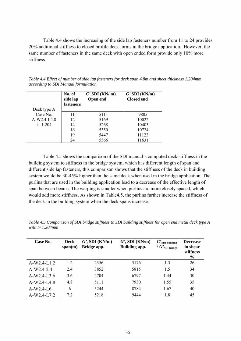
Table 4.4 shows the increasing of the side lap fasteners number from 11 to 24 provides 20% additional stiffness to closed profile deck forms in the bridge application. However, the same number of fasteners in the same deck with open ended form provide only 10% more stiffness.
Table 4.4 Effect of number of side lap fasteners for deck span 4.8m and sheet thickness 1.204mm
according to SDI Manual formulation
Table 4.5 shows the comparison of the SDI manual’s computed deck stiffness in the building system to stiffness in the bridge system, which has different length of span and different side lap fasteners, this comparison shows that the stiffness of the deck in building system would be 30-45% higher than the same deck when used in the bridge application. The purlins that are used in the building application lead to a decrease of the effective length of span between beams. The warping is smaller when purlins are more closely spaced, which would add more stiffness. As shown in Table4.5, the purlins further increase the stiffness of the deck in the building system when the deck spans increase.
Table 4.5 Comparison of SDI bridge stiffness to SDI building stiffness for open end metal deck type A
with t=1.204mm
Deck type A Case No.
A-W2.4-L4.8 t= 1.204
No. of
side lap
fasteners
G’,SDI (KN/ m)
Open end
G’,SDI (KN/m)
Closed end
11 5111 9805 12 5169 10022 14 5268 10403 16 5350 10724 19 5447 11123 24 5566 11631
Case No. Deck
span(m)
G’, SDI (KN/m)
Bridge app.
G’, SDI (KN/m)
Building app.
G’SDI building
/ G’SDI bridge
Decrease
in shear
stiffness
%
A-W2.4-L1.2 1.2 2356 3176 1.3 26 A-W2.4-2.4 2.4 3852 5815 1.5 34 A-W2.4-L3.6 3.6 4704 6797 1.44 30 A-W2.4-L4.8 4.8 5111 7930 1.55 35 A-W2.4-L6 6 5244 8784 1.67 40 A-W2.4-L7.2 7.2 5218 9444 1.8 45

36
Table 4.6 contains a comparison of closed end panel width 2.4m ( Type A) to closed end panel width 4.8m ( Type B) in shear stiffness results. The sheet thickness in this investigation was 1.204mm. The results in Table 4.6 indicate increases in shear stiffness when the panel width increases from 2.4m to 4.8m. These increases in shear stiffness are greater when the span of panel becomes greater.
Table 4.6 Effect of panel width on SDI shear stiffness of closed end metal deck, sheet thickness
(t) 1.204mm
Deck
span(m)
G’, SDI (KN/m)
Type A
G’, SDI (KN/m)
Type B
Increases
in the
shear
stiffness %
1.2 20098 21456 4 2.4 13843 15542 10 3.6 11403 13535 15 4.8 9805 12185 19 6 8640 10856 20
7.2 7741 10105 23
4.2.2 Analysis of ECCS Recommendation results
The comparison of the shear stiffness of closed end and open end deck forms, with a panel width of 2.4m (Type A), is shown in Table 4.7,4.8, and 4.9 for three types of thicknesses,1.204mm,0.909mm and 0.749mm, and reveals that the resistance to warping at the closed ends add more stiffness to the deck.
The results of this investigation show that the shear stiffness for open end deck forms increase when the span between two beams is increased, but the results of the closed end deck forms show considerable decreases in shear stiffness when the span is increased. These differences in the values of the shear stiffness depending on the shape of the end profile section can be attributed to the same reasons that were presented in the comparison of the SDI Manual results.
Table 4.7 Comparison of open end to closed end metal deck shear stiffness with panel type A
and sheet thickness 1.204mm according to ECCS Recommendation
Case No.
Deck
span(m)
G’ , ECCS (KN/m)
Increases
in shear
stiffness
% Open end Closed end
A-W2.4-2.4 2.4 1856 7509 75 A-W2.4-L3.6 3.6 2435 7131 65 A-W2.4-L4.8 4.8 2831 6651 57 A-W2.4-L6 6 3030 5961 49 A-W2.4-L7.2 7.2 3189 5609 43

37
Table 4.8 Comparison of open end to closed end deck panel shear stiffness with panel type A
and sheet thickness 0.904mm according to ECCS Recommendation
Case No.
Deck
span(m)
G’ , ECCS (KN/m)
Increases
in shear
stiffness
% Open end Closed end
A-W2.4-2.4 2.4 1031 7191 85 A-W2.4-L3.6 3.6 1429 6843 79 A-W2.4-L4.8 4.8 1752 6400 72 A-W2.4-L6 6 1977 5758 65 A-W2.4-L7.2 7.2 2169 5429 60
Table 4.9 Comparison of open end to closed end deck panel shear stiffness with panel type A
and sheet thickness 0.749mm according to ECCS Recommendation
Case No.
Deck
span(m)
G’ , ECCS (KN/m)
Increases
in shear
stiffness
% Open end Closed end
A-W2.4-2.4 2.4 675 6942 90 A-W2.4-L3.6 3.6 959 6618 85 A-W2.4-L4.8 4.8 1204 6202 80 A-W2.4-L6 6 1401 5598 74 A-W2.4-L7.2 7.2 1574 5286 70
The results in the tables above also indicate the effect of sheet thickness on shear stiffness. Tables 4.7, 4.8, and 4.9 present the results of calculations of shear stiffness for panel sheeting with different sheet thicknesses. The thicknesses that were used are: 1.204mm, 0.904mm and 0.749mm respectively. The shear stiffness values of open end deck forms with sheet thickness 0.909mm (Table4.7) represented a 30-44% reduction from the values with sheet thickness 1.204mm (Table4.8). The results in Table4.9 show a 27-34% decrease in stiffness when using a sheet thickness of 0.747 mm, compared to a sheet thickness of 0.904mm. The comparison in Tables 4.7, 4.8, and 4.9 for open end deck form illustrate the significant decreases in shear stiffness that can be expected when the thickness of the sheet is decreased. These decreases in stiffness are caused by the increase of flexibility due to distortion at the end of sheet. This flexibility and sheet thickness are inversely proportional, as shown in the flexibility due to distortion equation C2. The same tables also show the effect of sheet thickness on the shear stiffness for the closed end deck. The results of shear stiffness for the closed end deck form show only 3-4% decreases in stiffness when using a sheet thickness of 1.204mm compared to a sheet thickness of 0.909mm sheet thickness and the same magnitude of reduction of the shear stiffness when the thickness of the sheets reduces from 0.909mm to 0.749mm. This comparison of the shear stiffness values for the closed end deck form with different sheet thicknesses reveals that decreasing the sheet thickness causes smaller reduction in stiffness. The smaller reduction in stiffness is due to the fact that the

38
closed end sheet has more resistance to warping at the end of sheet and the fact that the equation of the flexibility due to distortion, which includes the thickness parameter, at the end of sheet was neglected in the calculation of the shear stiffness of the closed end deck form.
Table 4.10 contains a comparison of results from the calculation for shear stiffness in the bridge application and the results of shear stiffness with the same deck form in the building application. The width of the panel sheeting that was investigated is 2.4 m, and the thickness of the sheet is 1.204 mm. The investigation included variation in the deck span. The results show that the shear stiffness values for deck forms in building application are higher than the values of shear stiffness for the same deck forms in bridge application. The differences in the shear stiffness between these two applications are greater when the deck form span is increased.
Table 4.10 Comparison of ECCS bridge stiffness to ECCS building stiffness for open end deck form
with 1.204mm
Table 4.11 contains a comparison of results from the calculation of shear stiffness for closed end panel deck with overall panel width 2.4m and 4.8m. The sheet thickness in this investigation was 1.204mm. The results of Table 4.11 indicate increases in shear stiffness when the panel width increases from 2.4m to 4.8m. These increases in shear stiffness are greater when the span of panel increases.
Table 4.11 Shear stiffness comparison of closed end metal decks type A to type B, sheet
thickness is 1.204mm.
Deck
span(m)
G’, ECCS (KN/m)
Type A
G’, ECCS (KN/m)
Type B
Increases
in the
shear
stiffness %
2.4 7509 14465 48 3.6 7131 14390 50 4.8 6651 14008 52 6 5961 13001 54
7.2 5609 12657 55
Case No. Deck
span(m)
G’, ECCS
(KN/m)
Bridge app.
G’, ECCS
(KN/m)
Building app.
Decrease
in shear
stiffness
%
A-W2.4-2.4 2.4 1856 1830 1 A-W2.4-L3.6 3.6 2435 2531 3.7 A-W2.4-L4.8 4.8 2831 3204 11.6 A-W2.4-L6 6 3030 4088 25.8 A-W2.4-L7.2 7.2 3189 5009 36

39
4.2.3 Analysis of FEM results
As was presented earlier in the results from the SDI Manual and the ECCS Recommendation, the increases of the sheet thickness will add more stiffness to sheets, but these increases are not the same for both types of deck ends. The thickness of the sheet has more effect on the shear stiffness value in the open end deck form, while this effect is less in the closed end deck form. The results in Table4.12 show the shear stiffnesses for open end deck forms with 0.909mm sheet thickness represent a 45% reduction from the shear stiffnesses for open end deck forms with 1.204mm sheet thickness, and the reduction is 35% when the sheet thickness is reduced from 0.909mm to 0.749mm. The results of the shear stiffness on the closed end deck form in Table 4.13 illustrate a shear stiffness reduction of 23% when the thickness of the sheet is decreased from 1.204mm to 0.909mm and a 17% decrease in stiffness when the thickness is decreased from 0.909mm to 0.749mm.
Table 4.12 Shear stiffness comparison of overall panel width 2.4m (Type A)with overall panel
width 4.8m (Type B) for open end deck form and for different sheet thickness and different span
length..
Deck span
(m)
Deck thickness
(mm)
G’,FEM (KN/m)
Open end metal deck
Increases in
the G’ (%)
Panel Type A Panel Type B
2.4 1.204 3644 3977 8.3 0.904 1931 2047 5.6 0.749 1198 1275 6
4.8 1.204 5861 6538 10 0.909 3301 3634 9 0.749 2170 2366 8
7.2 1.204 5844 7536 22 0.909 3593 4469 19 0.749 2493 3019 17
Table 4.13 Shear stiffness comparison of overall panel width 2.4m (Type A) with panel width
4.8m (Type B) for closed end deck form and for different sheet thickness and different span length.
Deck span
(m)
Deck thickness
(mm)
G’, FEM (KN/m)
Closed end metal deck
Increases in
the G’ (%)
Panel Type A Panel Type B
2.4 1.204 17879 21656 17 0.909 12922 16201 20 0.749 9893 12758 22
4.8 1.204 14135 20126 30 0.909 10810 15574 30 0.749 8822 12761 40
7.2 1.204 9628 15979 41 0.909 7376 12558 41 0.749 6083 10494 42

40
The shear stiffness results in Table 4.12 for different span length show the increases in the stiffness when the panel span is increased while Table 4.13 illustrates the reduction in shear stiffness when the span is increased. The effect of the overall panel width on the shear stiffness is also given in Tables 4.12 and Table 4.13; these tables illustrate the increases in the stiffnesses when the panels’ width (Wd) increase from 2.4m (Type A) to 4.8m (Type B).
4.3 Comparison of results
Although the results of the three methods that were used in the shear stiffness investigations are different comparatively, the results show that the effect of parameters: sheet thickness, length of span and overall panel width on the shear stiffness is similar in spite of the method that was used.
4.3.1 The effect of the profile type at the deck ends
The investigation of the effect of both closed- and open- end deck form on the value of shear stiffness from the three methods reveals that the closed end of the deck adds more resistance to prevent this end from warping as it was presented earlier in the analysis of the results. The measurement of the effective shear stress (τ’) at the edges of both panels, open end and closed end, is the same. The difference in the shear stiffness for these two types is attributed to the effect of the shear strain. The shear distortion at the end of the open end sheet adds more flexibility to deformation and causes more shear deflection. The closed end of the sheet restricts this end from distorting and prevents the warping of the sheet. This will add more stiffness to the panel; therefore, the shear stiffness values for closed end deck form are higher than shear stiffness for open end deck form. As shown in Figure4.1, the difference in the shear stiffness values between closed- and open-end deck forms decreases when the deck span is increased.
Figure 4.1 Effect of the closed end and open end deck form on the value of shear stiffness
4.3.2 The effect of the sheet thickness
Several combinations of sheet thickness and type of the deck ends profile were investigated to determine the effect of the sheet thickness on shear stiffness and to determine which type of
0
1
2
3
4
5
6
0 1,2 2,4 3,6 4,8 6 7,2 8,4
G'cl
osed/G
'ope
n (%
)
Span length Ld (m)
Effect of the type of profiles at the deck ends on the effective shear stiffness G' (KN/m)
SDI Manual
ECCS Recommendation
FEM MethodSheet thickness=1.204mm

41
panel has been more influenced by the variation of sheet thickness. The values in Table 4.14 and Table 4.15 represent the reduction in shear stiffness as a result of reducing the thickness of the sheets. The values are based on the calculations using three different methods. The panel sheeting that was used in this comparison has a 2400mm overall panel width and 2400 panel span. Two type of deck ends were used in all the calculations. As shown in Table 4.14 and Table 4.15, the effect of the variation of sheet thickness on the shear stiffness is more in the open end deck profile than in the closed end. The smaller reduction in stiffness in the closed end deck form is due to the fact that the resistance to warping at the ends of the closed end deck form is higher. In this study, an assumption that the flexibility due to distortion at the deck ends is equal to zero was considered in the calculation of shear stiffness, according to SDI Manual and ECCS Recommendation. Actually, there is some distortion at the ends of the closed end deck form; therefore, the results from FEM show that the decreases in stiffness in the closed end deck form are greater than the decreases that were based on theoretical calculation, where the flexibility due to distortion at the ends is neglected.
Table 4.14 Reduction of shear stiffness in the open end deck form as a result to reduce sheet
thickness
Reduction of
thickness
SDI
%
ECCS
%
FEM
%
From 1.204mm to 0.909mm
43 44 47
From 0.904mm to 0.749mm
34 34 48
Table 4.15 Reduction of shear stiffness in the closed end deck form as a result to reduce the
sheet thickness
Reduction of
thickness
SDI
%
ECCS
%
FEM
%
From 1.204mm to 0.909mm
16 4 25
From 0.904mm to 0.749mm
11 4 21
4.3.3 The effect of the length of span
Several calculations were conducted to determine the effect of the length of span on shear stiffness using three different methods. The influence of the length of span on shear stiffness is similar in these three different methods. As was presented in the analysis of SDI Manual results earlier, the shear stiffness of the open ends deck form increase in a few manners when the length of span is increased but the stiffness of the closed end deck form decrease when its span is increased. A comparison of results from the calculations using SDI Manual, ECCS Recommendations and FEM are illustrated in Table4.16 and Table4.17. The investigations were conducted on the deck form that is used in bridge system and three spans were
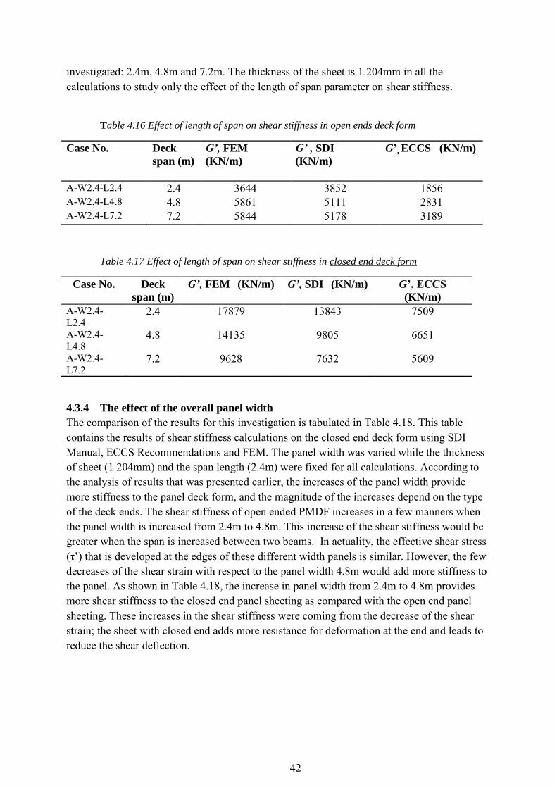
42
investigated: 2.4m, 4.8m and 7.2m. The thickness of the sheet is 1.204mm in all the calculations to study only the effect of the length of span parameter on shear stiffness.
Table 4.16 Effect of length of span on shear stiffness in open ends deck form
Case No. Deck
span (m)
G’, FEM
(KN/m)
G’ , SDI
(KN/m)
G’, ECCS (KN/m)
A-W2.4-L2.4 2.4 3644 3852 1856 A-W2.4-L4.8 4.8 5861 5111 2831 A-W2.4-L7.2 7.2 5844 5178 3189
Table 4.17 Effect of length of span on shear stiffness in closed end deck form
Case No. Deck
span (m)
G’, FEM (KN/m)
G’, SDI (KN/m) G’, ECCS
(KN/m)
A-W2.4-L2.4
2.4 17879 13843 7509
A-W2.4-L4.8
4.8 14135 9805 6651
A-W2.4-L7.2
7.2 9628 7632 5609
4.3.4 The effect of the overall panel width
The comparison of the results for this investigation is tabulated in Table 4.18. This table contains the results of shear stiffness calculations on the closed end deck form using SDI Manual, ECCS Recommendations and FEM. The panel width was varied while the thickness of sheet (1.204mm) and the span length (2.4m) were fixed for all calculations. According to the analysis of results that was presented earlier, the increases of the panel width provide more stiffness to the panel deck form, and the magnitude of the increases depend on the type of the deck ends. The shear stiffness of open ended PMDF increases in a few manners when the panel width is increased from 2.4m to 4.8m. This increase of the shear stiffness would be greater when the span is increased between two beams. In actuality, the effective shear stress (τ’) that is developed at the edges of these different width panels is similar. However, the few decreases of the shear strain with respect to the panel width 4.8m would add more stiffness to the panel. As shown in Table 4.18, the increase in panel width from 2.4m to 4.8m provides more shear stiffness to the closed end panel sheeting as compared with the open end panel sheeting. These increases in the shear stiffness were coming from the decrease of the shear strain; the sheet with closed end adds more resistance for deformation at the end and leads to reduce the shear deflection.
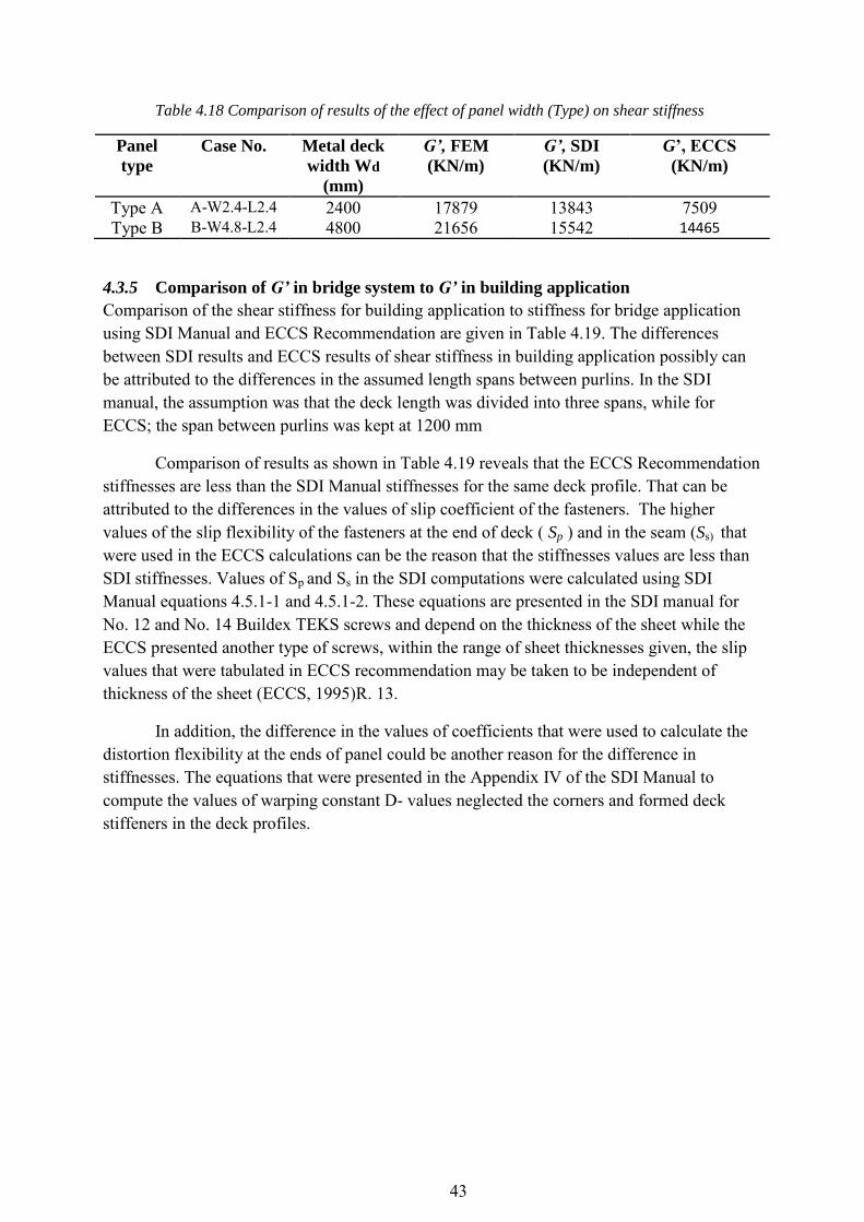
43
Table 4.18 Comparison of results of the effect of panel width (Type) on shear stiffness
Panel
type
Case No. Metal deck
width Wd
(mm)
G’, FEM
(KN/m)
G’, SDI
(KN/m)
G’, ECCS
(KN/m)
Type A A-W2.4-L2.4 2400 17879 13843 7509 Type B B-W4.8-L2.4 4800 21656 15542 14465
4.3.5 Comparison of G’ in bridge system to G’ in building application
Comparison of the shear stiffness for building application to stiffness for bridge application using SDI Manual and ECCS Recommendation are given in Table 4.19. The differences between SDI results and ECCS results of shear stiffness in building application possibly can be attributed to the differences in the assumed length spans between purlins. In the SDI manual, the assumption was that the deck length was divided into three spans, while for ECCS; the span between purlins was kept at 1200 mm
Comparison of results as shown in Table 4.19 reveals that the ECCS Recommendation stiffnesses are less than the SDI Manual stiffnesses for the same deck profile. That can be attributed to the differences in the values of slip coefficient of the fasteners. The higher values of the slip flexibility of the fasteners at the end of deck ( Sp ) and in the seam (Ss) that were used in the ECCS calculations can be the reason that the stiffnesses values are less than SDI stiffnesses. Values of Sp and Ss in the SDI computations were calculated using SDI Manual equations 4.5.1-1 and 4.5.1-2. These equations are presented in the SDI manual for No. 12 and No. 14 Buildex TEKS screws and depend on the thickness of the sheet while the ECCS presented another type of screws, within the range of sheet thicknesses given, the slip values that were tabulated in ECCS recommendation may be taken to be independent of thickness of the sheet (ECCS, 1995)R. 13.
In addition, the difference in the values of coefficients that were used to calculate the distortion flexibility at the ends of panel could be another reason for the difference in stiffnesses. The equations that were presented in the Appendix IV of the SDI Manual to compute the values of warping constant D- values neglected the corners and formed deck stiffeners in the deck profiles.

44
Table 4.19 Comparison of the shear stiffness between building application and bridge
application
Case No.
Deck
span
(m)
G’, SDI (KN/m)
Open end
SDI
G’building /
G’bridge
G’, ECCS (KN/m)
Open end
ECCS
G’ building /
G’ bridge
Bridge Building Bridge Building
A-W2.4-2.4 2.4 3852 5815 1.5 1856 1830 1 A-W2.4-L3.6 3.6 4704 6797 1.44 2435 2531 1.03 A-W2.4-L4.8 4.8 5111 7930 1.55 2831 3204 1.13 A-W2.4-L6 6 5244 8784 1.67 3030 4088 1.35 A-W2.4-L7.2 7.2 5218 9444 1.8 3189 5009 1.57
4.3.6 Comparison of shear stiffness values from SDI, ECCS and FEM.
This section contains a comparison of calculated shear stiffness values for PMDF in the bridge system using SDI Manual and ECCS Recommendations to PMDF shear stiffness values that were computed using the ABAQUS program. The purpose of this comparison was to determine if the theoretical calculated stiffnesses were of the same magnitude as FEM shear stiffness, which was computed using the ABAQUS program. Table 4.20 and Table 4.21 contain the calculated shear stiffness values for panel sheeting with a width of 2.4m and with different spans. The variety of the thickness of sheets was considered in this investigation. Table 4.20 shows calculations for the open end deck forms and Table 4.21 shows calculations for closed end deck forms. Figure 4.2 and Figure 4.3 show a comparison of stiffnesses values for open end and closed end metal deck.
Table 4.20 comparison of SDI, ECCS and FEM shear stiffness values for open end metal deck
Tape A
Case No.
Deck
span
(m)
t*
(mm)
G’, FEM
(KN/m)
G’, SDI
(KN/m)
G’, ECCS
(KN/m)
G’FEM /
G’SDI
G’FEM /
G’ECCS
A-W2.4-L2.4-t
2.4 1.204 3644 3852 1856 0.9 2.0
0.909 1931 2042 1031 0.9 1.9
0.749 1198 1432 675 0.8 1.8
A-W2.4-L4.8-t
4.8 1.204 5861 5111 2831 1.1 2.1
0.909 3301 3104 1752 1.1 1.9
0.749 2170 2295 1204 0.9 1.8
A-W2.4-L7.2-t 7.2 1.204 5844 5178 3189 1.1 1.8
0.909 3593 3469 2169 1.0 1.7
0.749 2493 2686 1574 0.9 1.6

45
0
1000
2000
3000
4000
5000
6000
7000
0 1,2 2,4 3,6 4,8 6 7,2 8,4
G'c
lose
d (
KN
/m)
Span length Ld (m)
comparison of shear stiffness G' for open end metal deck
SDI Manual
ECCS Recommendation
FEM Method
*t= sheet thickness
Figure 4.2 Comparison of SDI, ECCS and FEM stiffnesses for open end metal
deck,sheet thickness 1.204mm
Table 4.21 comparison of SDI, ECCS and FEM shear stiffness values for closed end metal
deck Type A
Case No.
Deck
span
(m)
t*
(mm)
G’, FEM
KN/m
G’, SDI
KN/m
G’, ECCS
KN/m
G’FEM
/ G’SDI
G’FEM /
G’ECCS
A-W2.4-L2.4-t
2.4 1.204 17879 13843 7509 1.3 2.4
0.909 12922 11611 7191 1.1 1.8
0.749 9893 10254 6942 1.0 1.4
A-W2.4-L4.8-t
4.8 1.204 14135 9805 6651 1.4 2.1
0.909 10810 8310 6400 1.3 1.7
0.749 8822 7395 6202 1.2 1.4 A-W2.4-L7.2-t 7.2 1.204 9628 7632 5609 1.3 1.7
0.909 7376 6505 5429 1.1 1.4
0.749 6083 5813 5286 1.0 1.2
*t= sheet thickness
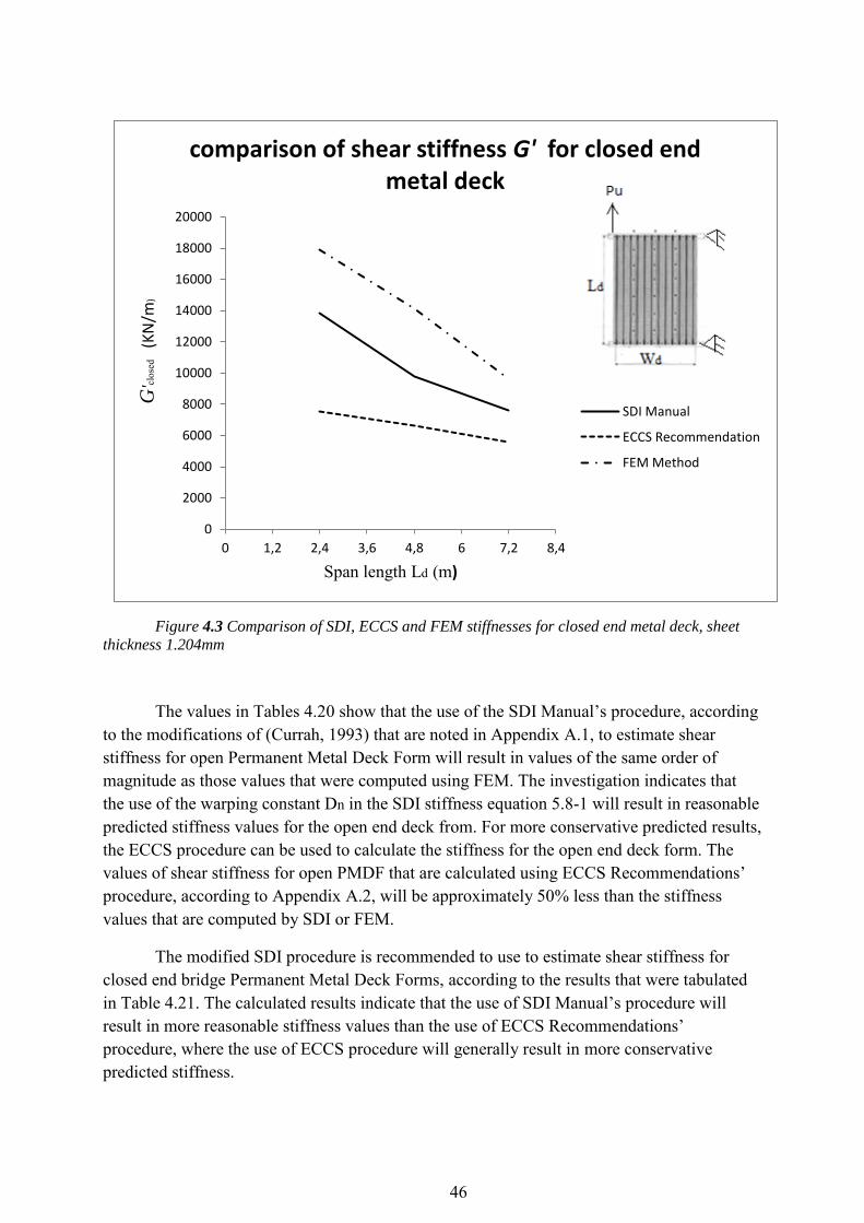
46
0
2000
4000
6000
8000
10000
12000
14000
16000
18000
20000
0 1,2 2,4 3,6 4,8 6 7,2 8,4
G'c
lose
d (
KN
/m)
Span length Ld (m)
comparison of shear stiffness G' for closed end metal deck
SDI Manual
ECCS Recommendation
FEM Method
Figure 4.3 Comparison of SDI, ECCS and FEM stiffnesses for closed end metal deck, sheet
thickness 1.204mm
The values in Tables 4.20 show that the use of the SDI Manual’s procedure, according to the modifications of (Currah, 1993) that are noted in Appendix A.1, to estimate shear stiffness for open Permanent Metal Deck Form will result in values of the same order of magnitude as those values that were computed using FEM. The investigation indicates that the use of the warping constant Dn in the SDI stiffness equation 5.8-1 will result in reasonable predicted stiffness values for the open end deck from. For more conservative predicted results, the ECCS procedure can be used to calculate the stiffness for the open end deck form. The values of shear stiffness for open PMDF that are calculated using ECCS Recommendations’ procedure, according to Appendix A.2, will be approximately 50% less than the stiffness values that are computed by SDI or FEM.
The modified SDI procedure is recommended to use to estimate shear stiffness for closed end bridge Permanent Metal Deck Forms, according to the results that were tabulated in Table 4.21. The calculated results indicate that the use of SDI Manual’s procedure will result in more reasonable stiffness values than the use of ECCS Recommendations’ procedure, where the use of ECCS procedure will generally result in more conservative predicted stiffness.
47
5 Shear forces in the fasteners between metal decks and beams Suitable structural connections are used to transmit diaphragm forces to the main steel members (called plates in this investigation). The sheeting should be attached with fasteners which carry shear forces without reliance on friction or bending of the fasteners themselves (ECCS, 1995, p. R14). Both ends of the sheets should be attached to the supporting members by means of self-tapping screws (Ø6.3mm) with ensure that will not work loose in service, pull out, or fail in shear before causing tearing of the sheeting. All such fasteners should be fixed directly through the trough of profiled sheets into the supporting member, to ensure that the connections effectively transmit the forces assumed in the design.
The seams between adjacent sheets are fastened by self-drilling screws this type will not work loose in service, pull out, or fail in shear before causing tearing of the sheeting. The spacing of such fasteners should not exceed 500mm. The distances from all fasteners to the edges and ends of the sheets will be (12.5mm); these distances are adequate to prevent premature tearing of the sheets (ECCS, 1995, p. R18).
In consideration of the possibility that the panel sheeting might be continuous from one or two sides along the long axis of the girder, a beam (called stiffener in this investigation) was used as an adjacent sheet to the first -and last- sheet of the panel sheeting as shown in Figure 5.2 and Figure 5.3. The tie connection was used to connect the long side edge of the sheet to the stiffener. In addition to that, the hinge connection was used to attach the end of the stiffener to the edge of the plate. The hinge connection was used to ensure that these stiffeners would not add any stiffness to the system and not work as a bracing element.
5.1 Determination of fasteners forces with ABAQUS
Two models were used to investigate the fastener forces. One was panel sheeting without stiffeners and one with stiffener. The panel sheeting contained one, two, three and four sheets respectively. In the first, attachment points were created to define the location of the fasteners’ positioning points. Shear fasteners would be attached in every trough of profiled sheets at the end edge of the panel using the Face-to Face attachment method by ABAQUS and using maximum layers for projection to ensure that all layers of sheets fastened together with the plate elements. Fasteners were assumed to have a circular projection onto the connected surfaces and the physical radius was 3.2mm. The assembled connection category type is beam (rigid fastener) where all degrees of freedom are constrained to eliminate the moving of fasteners (Documentation, 2012).
Point-based fasteners were used to create Mesh –independent point fasteners by ABAQUS. These allowed for conveniently defining point-to-point connections between surfaces because they can be located anywhere between surfaces. In addition to that, they can connect multiple layers and the fastener acts over a specified radius of influences (Figure 5.1).

48
Figure 5.1 Fasteners layout between layers (Documentation, 2012)
5.2 Finding stiffener (edge member) with ABAQUS
The creation of a part as a beam was used to create the stiffeners. The beam section is 50x50x5 mm (width x height x thickness) and the property is the same for sheets with elasticity of 210 GPa and a poisson’s ratio 0.3. The ends were attached to the ends of the plate edges using a hinge connection in one node for each end to ensure the flexibility in the movement at the ends of stiffener. The hinge connection was created using a tie connection between two parts at the specified nodes by releasing the tie rotational degrees of freedoms. The attachment between the beam surface and the edge of the sheet along the span of sheet was created by using a tie connection; the distance between points was 400mm. The location of the stiffeners in the model and location of the tie connection are shown in Figure 5.2and Figure 5.3 respectively.
Figure 5.2 Panel sheeting with stiffeners
element Figure 5.3 Tie connections between
stiffeners and long side edge of sheet
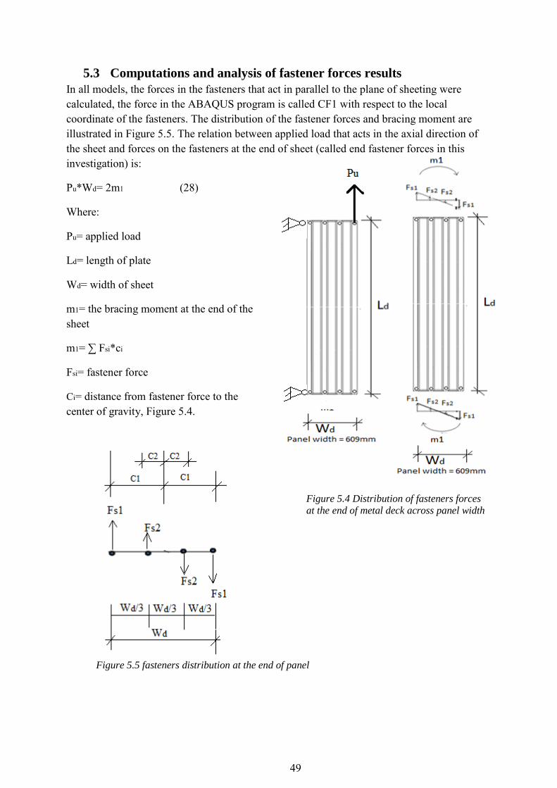
49
5.3 Computations and analysis of fastener forces results
In all models, the forces in the fasteners that act in parallel to the plane of sheeting were calculated, the force in the ABAQUS program is called CF1 with respect to the local coordinate of the fasteners. The distribution of the fastener forces and bracing moment are illustrated in Figure 5.5. The relation between applied load that acts in the axial direction of the sheet and forces on the fasteners at the end of sheet (called end fastener forces in this investigation) is:
Pu*Wd= 2m1 (28) Where:
Pu= applied load
Ld= length of plate
Wd= width of sheet
m1= the bracing moment at the end of the sheet
m1= ∑ Fsi*ci
Fsi= fastener force
Ci= distance from fastener force to the center of gravity, Figure 5.4.
Figure 5.4 Distribution of fasteners forces
at the end of metal deck across panel width
Figure 5.5 fasteners distribution at the end of panel

50
5.3.1 Effect of side lap fasteners
5.3.1.1 Sheet without side lap fasteners
The relation between applied load and the forces that act on the end fasteners in every trough has been derived as shown below (Figure 5.6):
Wd = 0.609mm
2Fs1*c1+2Fs2*c2=m1 (29)
That’s lead to
Fs2 =
Fs1
Substitute: c1 = Wd /2 , c2 = Wd/6 , Fs2 = Fs1 / 3
in Eq. 29, so that lead to
(10/9) Fs1* Wd = m1 (30)
The substitution of (m1) in Eq.30 with (m1) in Eq. 28 results in:
Pu*Wd= 2m1 (28) [Wd= 0.609mm]
Pu*0.609= 2[(10/9) Fs1* 0.609]
The resolve of the equation above results in the relation between lateral applied load and fasteners forces at the end of panel
Fs1 = 0.45 Pu
Figure 5.6 Fastener forces for sheet without sidelap
fasteners

51
5.3.1.2 Sheet with side lap fasteners
The relation between fasteners force and the applied load was derived according to the fastener forces distribution as shown in Figure 5.6. This relation is based on the assumption that the force in each side lap fastener is equal to Fs1. The relation between force on the end fastener and applied load will be as shown below:
Pu*Wd= 2m1
2(2.5 Fs1+ Fs1)*c1+ 2( Fs2*c2)=m1
Fs2 =
Fs1
C1 = Wd , C2 = Wd/6 , Fs2 = 0.33 Fs1
Wd= 609mm
3.55*Fs1 * Wd= m1 (31)
From (28) and (31)
Fs1 = 0.14 Pu
It appears that use of side lap fasteners to attach the adjacent sheets will result in a reduction of approximately 65% in the forces that act on the end fasteners. Fastener force that acts on each fastener across the width of panel for different types of panels (panel sheeting of one, two, three and four sheets) is shown in Table 5.1. Both stiffened and unstiffened sheeting was investigated. The forces calculated using ABAQUS are based on applying a concentrated load of 120000 N on the free end of plate in the axial direction of the panel sheeting.
Figure 5.7 Fastener force and bracing moment for stiffened sheet

52
Table 5.1 Distribution of fasteners shears forces at the ends edge of the panel with different
number of sheets. (Applied load Pu= 120000 N, deck span Ld = 2400mm))
Sh
eet nu
mb
er
Fa
stener #
Fs (N) Fs (N) Fs (N)
Fs (N)
unstiffened stiffened unstiffened stiffened unstiffened stiffened unstiffened stiffened Sheet
1
1 57853 23821 39822 21259 31927 18892 28600 7500 2 24116 7746 28622 10646 23697 9720 20744 1012 3 -24926 -7627 -9117 -1882 -9541 -2305 -8010 -9617 4 -58029 -24887 -31000 -25100 -26900 -23600 -23700 -16000
Sheet
2
4 31000 25100 26900 23600 23700 16000 5 7500 234 5805 4440 5450 3596 6 -28433 -9703 -2599 -1111 -519 -870 7 -43000 -23418 -28900 -25800 -27900 -24100
Sheet
3
7 28900 25800 27900 24100 8 7956 423 4493 4502 9 -25485 -9344 -2260 -308 10 -39003 -23841 -28200 -26600
Sheet
4
10 28200 26600 11 7093 2666 12 -24961 -6641 13 -39366 -23032
A comparison of end fasteners forces in the unstiffened panels to fasteners forces in the stiffened panels is presented in Table 5.2. Each value in Table 5.2 presents a ratio of fastener force to applied load. Different types of panel sheeting were investigated by ABAQUS. The table shows how this ratio changes according to the number of attached sheets and the results shows also the effect of adjacent sheeting on the fasteners forces at the end of metal deck.
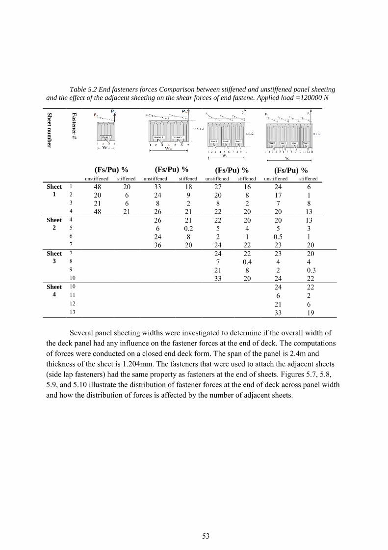
53
Table 5.2 End fasteners forces Comparison between stiffened and unstiffened panel sheeting
and the effect of the adjacent sheeting on the shear forces of end fastene. Applied load =120000 N
Sh
eet nu
mb
er
Fa
stener #
(Fs/Pu) %
(Fs/Pu) % (Fs/Pu) % (Fs/Pu) % unstiffened stiffened unstiffened stiffened unstiffened stiffened unstiffened stiffened
Sheet
1
1 48 20 33 18 27 16 24 6 2 20 6 24 9 20 8 17 1 3 21 6 8 2 8 2 7 8 4 48 21 26 21 22 20 20 13
Sheet
2
4 26 21 22 20 20 13 5 6 0.2 5 4 5 3 6 24 8 2 1 0.5 1 7 36 20 24 22 23 20
Sheet
3
7 24 22 23 20 8 7 0.4 4 4 9 21 8 2 0.3 10 33 20 24 22
Sheet
4
10 24 22 11 6 2 12 21 6 13 33 19 Several panel sheeting widths were investigated to determine if the overall width of
the deck panel had any influence on the fastener forces at the end of deck. The computations of forces were conducted on a closed end deck form. The span of the panel is 2.4m and thickness of the sheet is 1.204mm. The fasteners that were used to attach the adjacent sheets (side lap fasteners) had the same property as fasteners at the end of sheets. Figures 5.7, 5.8, 5.9, and 5.10 illustrate the distribution of fastener forces at the end of deck across panel width and how the distribution of forces is affected by the number of adjacent sheets.

54
Figure 5.9 Distribution of fasteners force for two
sheets panel
Figure 5.8 Distribution of fasteners
force for one sheet panel
Figure 5.11 Distribution of fasteners
force for four sheets panel
Figure 5.10 Distribution of fasteners force for
three sheets panel

55
5.3.2 Effect of sheet thickness
Three types of sheet thicknesses were tested by ABAQUS to examine the variation in the fasteners force. The percentages (Fs/Pu) of forces that act on the fastener at the end of panel (2400mm x 2400mm) are shown in Table 5.3. The applied load was 120000N for all tests.
Table 5.3 the percentage of forces value that act on the end fasteners that found in the
stiffened or unstiffened panel. Panel sheeting 2400mm X 2400mm. Applied load =120000N.
Sh
eet
nu
mb
er
Fa
stener #
(Fs/Pu) %
t* = 1.204mm
(Fs/Pu) %
t = 0.909mm
(Fs/Pu) %
t = 0.749mm
unstiffened stiffened unstiffened stiffened unstiffened stiffened
Sheet 1 1 24 14 24 14 25 14 2 17 6 18 7 19 8 3 7 1 6 0 4 1 4 20 18 20 18 20 10
Sheet 2 4 20 18 20 18 20 10
5 5 3 6 4 7 5 6 0 1 2 2 3 3
7 23 20 23 20 24 20 Sheet 3 7 23 20 23 20 24 20
8 4 4 5 4 6 5 9 2 0 4 2 5 3 10 24 22 23 22 22 21
Sheet 4 10 24 22 23 22 22 21 11 6 2 5 3 4 4 12 21 6 21 7 21 7 13 33 19 32 18 31 17
*t= Sheet thickness
The effect of the sheet thickness variation is shown in Figure 5.11 and Figure 5.12 below. Sheets with thicknesses 1.204mm, 0.909mm and 0.749mm were investigated for panel sheeting (2400mm x 2400mm) with both stiffened and unstiffened edges. The results show that the variation in the sheet thickness causes a minor effect on the fastener forces; forces increased on the fasteners that were used to fasten thinner sheets. This increase in the force that acts on the fasteners can be attributed to the fact that the thicker sheet is stiffer and has more resistance to deformation, which leads to reducing the forces that acts on the fasteners. The stiffeners would contribute to reducing the fasteners force generally as shown in Figure 5.12.

56
-60
-40
-20
0
20
40
60
80
100
120
0 203 406 609 812 1015 1218 1421 1624 1827 2030 2233 2436
(Fs/
Pu
) %
Wd (mm)
Distribution of the fasteners force for unstiffened panel sheetig for different sheet thicknesses
sheet thickness 1.204mm
sheet thickness 0.904mm
sheet thickness 0.747mm
Ld=2
40
0m
m
Ld=2
40
0m
m
Pu = 120000
Figure 5.12 Effect of the sheet thickness in unstiffened panel on the fastener forces

57
-40
-20
0
20
40
60
80
100
0 203 406 609 812 1015 1218 1421 1624 1827 2030 2233 2436
(Fs/
Pu
) %
Width (mm)
Distribution of the fasteners force for stiffened panel sheeting for different sheet thicknesses
sheet thickness 1.204mm
sheet thickness 0.904mm
sheet thickness 0.747mm
Figure 5.12 Effect of sheet thickness in stiffened panel on the fastener forces
Pu=120000

58
5.3.3 The Effect of the span length on the fasteners force
Three different span lengths were tested by ABAQUS to examine the effect of variation of the span length on the fasteners forces. 2.4m, 4.8m and 7.2m spans were tested with consideration to whether or not the edges of the sheets were adjacent. A part with a wire shape and a beam section were created by ABAQUS to achieve the adjacent element, as shown in Figure 5.13, and the material properties of this element correspond with the properties of the sheeting. A tie connection with a hinge property was used to connect the ends of the beam elements to the edge of the longitudinal plate; the connection was node to node. A tie connection as surface to node was used to attach the side lap of the sheet to the beam element, while side lap fasteners were used to connect adjacent sheets.
Figure 5.13 Panel sheeting with beams element as assembly elements by ABAQUS
There were three types of panel sheeting used in the test by ABAQUS. Dimensions of panels that were used in the investigation and the cases of tests are tabulated in Table 5.4.
Table 5.4 Dimensions of panel sheeting and cases of tests that used in the investigation, t =
1.204mm
Case No. Dimension Wd (mm) X Ld (mm)
A-W2.4-L2.4-t1.204 2400 X 2400 A-W2.4-L4.8-t1.204 2400 X 4800 A-W2.4-L7.2-t1.204 2400 X 7200
The results of the ratio of shear fasteners force to the applied load for panel sheeting with different spans are presented in Table 5.5.

59
Table 5.5 Effect of the length of span on fastener forces at the ends of metal deck
Sh
eet #
Fa
stener #
(Fs/Pu) %
Case No.
A-W2.4-L2.4-t1.204
A-W2.4-L4.8-t1.204
A-W2.4-L7.2-t1.204
Sheet 1
1 14 9 8 2 6 5 4 3 -1 3 3 4 -18 -8 -6
Sheet 2
4 18 8 6 5 3 2 2 6 -1 -1 -1 7 -20 -9 -7
Sheet 3
7 20 9 7 8 4 1 0 9 0 0 -1 10 -22 -9 -7
Sheet 4
10 22 9 7 11 2 -1 -2 12 -6 -4 -4 13 -19 -10 -8
Comparison of results reveals that the fastener forces at the end of sheets are reduced when the span of the panel is increased, as shown in Figure 5.14.

60
-40
-20
0
20
40
60
80
100
0 203 406 609 812 1015 1218 1421 1624 1827 2030 2233 2436
(Fs/
Pu
) %
Width (Wb)
Distribution of fasteners force for different span length (stiffened edges)
Panel 2400mm X 2400mm
Panel2400mm x 4800mm
Panel 2400mm x 7200mm
(Panel Wd x Ld)
Pu= 120000 N
Figure 5.14 Distribution of fastener forces at the end of metal deck and across the panel width for
different length of span
The fastener forces distribution for panel sheeting with different spans indicates a reduction in the fastener force that acts on the fastener. This reduction of the fastener force value can be attributed to the increase of the number of side lap fasteners that contributed to decrease the force that acts on the ends fasteners as shown in the calculation below:
Panel sheeting 2400 x 2400
Pu*Wd= 2m1 (a1)
2(2.5 Fs1+ Fs1)*c1+ 2 (Fs2*c2)=m1 (b1)
Fs2 = (1/3) Fs1
C1 = Wd / 2 , C2 = Wd/6 , Fs2 = 0.33 Fs1
Ld

61
Wd= 609mm
From (a1) and (b1)
Fs1 = 0.14 Pu
Figure 5.15 panel sheeting with span 2.4m and the number of side lap fasteners is 5 on each
side
Panel sheeting 2400 x 4800
Pu*Wd= 2m1 (a2)
2[(5.5 Fs1+ Fs1)*c1]+ 2( Fs2*c2)=m1 (b2)
Fs2 = (1/3) Fs1
C1 = Wd /2 , C2 = Wd/6 , Fs2 = 0.33 Fs1
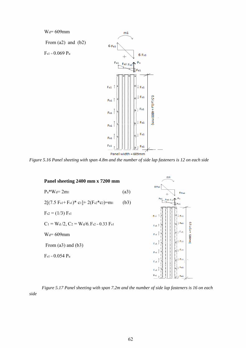
62
Wd= 609mm
From (a2) and (b2)
Fs1 = 0.069 Pu
Figure 5.16 Panel sheeting with span 4.8m and the number of side lap fasteners is 12 on each side
Panel sheeting 2400 mm x 7200 mm
Pu*Wd= 2m1 (a3)
2[(7.5 Fs1+ Fs1)* c1]+ 2(Fs2*c2)=m1 (b3)
Fs2 = (1/3) Fs1
C1 = Wd /2, C2 = Wd/6, Fs2 = 0.33 Fs1
Wd= 609mm
From (a3) and (b3)
Fs1 = 0.054 Pu
Figure 5.17 Panel sheeting with span 7.2m and the number of side lap fasteners is 16 on each
side

63
Conclusion The primary objective of this study was the theoretical calculation of effective shear stiffness for Permanent Metal Deck Forms in the bridge system and to compare the results with calculated stiffness values for the panel sheeting in building application. An investigation of the effect of deck ends profile types, length of deck span, sheet thickness and deck width on the calculation of shear stiffness was conducted.
The determination of the fastener forces distribution across the deck width and an investigation of the effect of side lap fasteners, panel length and sheet thickness on the forces that act on the fasteners at the end of deck was also included in this study.
The investigation to find a procedure that can be used to estimate a shear stiffness value for PMDFs in the bridge system revealed that the results from the modified SDI Manual’s procedure can be used to estimate reasonable stiffness values for closed- and open-end deck forms. The calculations using ECCS Recommendations’ procedure resulted in conservative estimated stiffness values, where the magnitude of stiffness represented a reduction of approximately 50% compared to the stiffness that was calculated using the SDI procedure. The decreases in stiffness value, according to ECCS, could be attributed to the higher values of coefficients, such as the warping constant and fasteners slip coefficient that were used in ECCS Procedure.
The calculation of shear stiffness for Permanent Metal Deck Forms that are used in building application revealed that the use of purlins in building application provide more stiffness to deck panels when intermediate purlins are used to reduce the effective length between beams (primary members).
The effect of the span length on the value of shear stiffness in bridge system investigations showed that an increase of the span in the open-end deck form would cause a small increase in shear stiffness, the warping relaxation is smaller when the length of the span is increased (Dn= D/12L SDI Manual). Therefore, the longer span provides less warping constant and less warping relaxation at the ends which slightly adds stiffness. The increase in the span reduced the shear stiffness for the same panel with a closed-end profile type where increasing the length of the span would provide more shear flexibility to the deck and increase the total shear deflection for all corrugations in spite of the fact that closed ends add some resistance to warping at the ends. In addition, the discrete connections at panel side laps further increase the relaxation for deflection under load where. The slip coefficient C for these connections depends directly on the length of span, the increase in the length of span leads to increase the slip coefficient C and as a result reduces the stiffness.
Generally, the closed end profile deck provided a noticeable increase in shear stiffness. As a result, there was a reduction of approximately 43% in shear stiffness in the open-end deck when the thickness of the sheet was reduced from 1.204mm to 0.909mm and a reduction of approximatly34% when the thickness was reduced to 0.749mm. The investigation on the closed-end deck form resulted in a reduction of 16% when thickness was

64
reduced from 1.204mm to 0.909mm, and reduction of 11% when thickness was reduced from 0.909 to 0.749mm. Increasing the overall panel width provided the stiffness of panel.
Increasing the panel width from 2.4m to 4.8m increased the stiffness of the panel. These increases in the shear stiffness were a result of the decrease of the shear strain; the sheet with closed end added more resistance for deformation at the end and led to a reduction of the shear deflection.
The results for another aim for this study showed that the variation in the sheet thickness caused a minor effect on the fastener forces; forces would be increased on the fasteners that fasten thinner sheets. The investigation showed that using side lap fasteners to attach the adjacent sheets will result in a reduction of approximately 65% in the forces that act on the end fasteners. The investigation of fastener forces distribution for panel sheeting with different spans indicated a reduction in the fastener force that act on the fastener when the span is increased.
For further study, the calculation of shear stiffness for deck form in the bridge application with consideration of dimensions for girders as a reality with using supporting angles will help to understand PMDF behavior as shear diaphragm. An investigation on distribution load would also be interesting to compare with the result of shear stiffness with concentrated load. Further investigations on the fastener forces are required to include the use of non-rigid screws and for different transversal configurations.

65
6 Bibliography Currah, R. M., 1993. Shear strength and shear stiffness of permanent steel bridge deck forms,
austin: the university of texas.
Documentation, A. 6. O., 2012. Abaqus/CAE User's Manual. Mesh-independent fasteners,
section 34.3.4. [Online] Available at: http://abqdoc.byv.kth.se:2080/v6.12/books/popups/info.html [Använd 5 10 2013].
ECCS, P., 1995. European Recommendations for the Application of Metal Sheeting acting as
a Diaphragm-Stressed Skin Design. No 88 red. u.o.:u.n.
Eder, D., 2003. FE-Analysis of the Deformations at the End of TrapezoidallyCorrugated
Sheeting, Stockholm: Royal Institution of Technology,structural engineering,SE- 100 44 .
Egilmez, O., Jetann, T. A. & Lowery, a. R., 2007. Stiffness and Strength of Metal Bridge Deck Forms. JOurnal of bridge engineering, 12(429), pp. 429-437.
Egilmez, O., Todd, A. H. & Herman, R., 2012. Buckling Behavior of Steel Bridge I-Girders Braced by Permanent Metal Deck Forms. Journal of bridge engineering, Volym 17, pp. 624-633.
Helwig, T. A. & Frank, K. H., 1999. Diaphragm stiffness requirements for beam bracing. Journal of Structural Engineering, 125(11), pp. 1249-1256.
Helwig, T. A., Frank, K. H. & Yura, J. A., 1997. Lateral-torsional buckling of singly-symmetric. I: beams.. Journal of Structural Engineering, 123(9), pp. 1172-1179.
Helwig, T. A. & Yura, J. A., 2008. Shear Diphragm Bracing of Beam. II: design requirements. journal of structural engineering, 134(N.3), pp. 360-361.
kathage, K., Lindner, j., Misiek, T. & schilling, S., 2013. a proposal to adjust the design approach for the diaphragm action of shear panels according to Schardt and Strehl in line eith European regulations. Steel Construction , 6(No.2), pp. 107-116.
Luttrell, L., 1995. Steel Deck Institution Diaphragm Disign Manual,. Second edition red. Canton: Ohio.
Mashayekhi, D. M., 2013. Element Selection Criteria. [Online] Available at: http://mashayekhi.iut.ac.ir/sites/mashayekhi.iut.ac.ir/files//u32/presentation10.pdf [Använd 25 11 2013].
Ottosen, N. & Petersson, H., 1992. Introduction to thje finite element method. New York: Prentice Hall.
Todd A. Helwig, J. A. Y., 2008. shear diaphragm bracing of beams. I: stiffness and strength behavior. journal of structural engineering, 134(No.3), pp. 384-356.

66
Todd A. Hlwig, K. H. F., November 1999. Stiffness Requirements for Diaphragm Bracing of Beam. jornal of structural engineering , 125(No.11), pp. 1249-1256.
Todd helwig, O. E. a. C. J., 2005. Lateral Bracing of Bridge Girders by Permanent metal
Deck Forms, Houston: Texas Department of Transpotation.
Wright, H. D. & Hossain, K. M. A., 1997. In-Plane Shear Behaviour of Profiled Steel
Sheeting. Glasgow,U.K., Deparment of Mechanical Engineering,University of Strathclyde.

67
Appendix A
Examples of shear stiffness calculations
1. Example of calculation shear stiffness according to SDI Manual
Connector slip parameter
The slip coefficient C depends on the thickness of the profile that has been selected, length of panel (span), the arrangement of the fasteners and the number and location of fasteners in a panel.
Equation 3.3-1 of the Second Edition of the SDI Manual represents simplified equation for the connection slip parameter. This is equation based on the assumption that the number of intermediate edge connectors (ne ) are equal to the number of side lap fasteners (ns) , this equation is more useable in the building applications. For bridge systems there are no intermediate edge connectors, that is means (ne ) does not equal (ns) and the more exact equation will be used for C this equation can be found in the Page 28 of the Steel Deck Institute Diaphragm Design Manual (First edition) as below
∑
where: L = Panel length ( deck sheet span length (feet)
a = Overall diaphragm panel width (inch)
nsh = Number of individual deck sheets in panel
np = Number of purlins ( zero for bridge application)
ns = Number of side lap fasteners per seam
Wsh = Individual deck sheet width (inch)
α2 = 0, for no purlins
t = thickness of sheet (inch)
ne = Number of edge connectors ( zero for all models)
Xe = Distance from individual deck sheet centerline to any fastener in a deck sheet at the end fasteners (inch).
Sf = Structural connector, which connecting sheets to beams, flexibility.
Ss = Side lap connector, which connecting adjacent panels, flexibility.

68
Sf and Ss are defined respectively in the second edition of the SDI Manual by equations 4.5.1-1 and 4.5.1-2 respectively.
Sf = 0.0013/(t)0.5 (in./kip)
Ss = 0.003/(t)0.5 (in/kip)
Structural connection is a fastener connecting one or more sheets to heavier frame or structural members. Values for it are indicated by a subscript f.
Sidelap connection is a fastener connecting adjacent panels to each other but not connecting to the frame members. Stitch connection is same as sidelap connection Values for it are indicated by subscript s.
Note: all dimensions would be taken in US unit; it’s easier to substitute in the SDI Manual equations.
L= 8’
a = 96’’
nsh = 4
ns =5
wsh =24’’
np =0
α2 =0
∑Xe= Xe1+Xe2+Xe3+Xe4
α1 = ∑Xe / Wsh
α1 = 1.33
sf = 0.0013/(0.048)0.5
ss = 0.003/(0.048)0.5
C = [24*29500 *8*0.048*0.00593/97.6] * [ ]
[ ] = [((4-1)/(2*1.33+0+2*5*0.00593/0.01369))+(1/(2*1.33+0+0))] = 13.29
Warping constant
The warping constant Dn is used to measure the warping relaxation at the ends of the diaphragm panels. The warping depends on the span and thickness of the profile. Obviously
Figure A. 1 Open profile diaphragm geometries

69
the warping is smaller with frequently spaced end connections and penetrates the diaphragm less when purlins are more closely spaced.
The warping constant is defined in the second edition of the SDI Manual as:
Dn = D/12L (SDI Eq. 3.3-2)
The D-value is developed in appendix IV of SDI Manual and depends on the distribution of end fasteners. Values are established for DW1 through DW4 representing D- values for end fasteners located in each, alternate, every third, and fourth valleys respectively. The D-values equations are presented below.
Deck profile dimensions required in the D-value equations are defined in Figure A. 2 with attention to all radius corners are squared-off and formed deck stiffeners are neglected for the purpose of determining the deck profile dimensions.
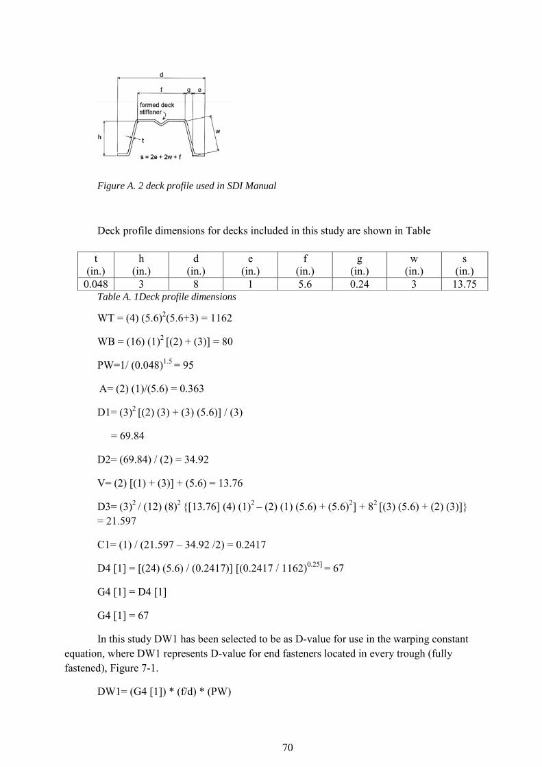
70
Figure A. 2 deck profile used in SDI Manual
Deck profile dimensions for decks included in this study are shown in Table
Table A. 1Deck profile dimensions
WT = (4) (5.6)2(5.6+3) = 1162
WB = (16) (1)2 [(2) + (3)] = 80
PW=1/ (0.048)1.5 = 95
A= (2) (1)/(5.6) = 0.363
D1= (3)2 [(2) (3) + (3) (5.6)] / (3)
= 69.84
D2= (69.84) / (2) = 34.92
V= (2) [(1) + (3)] + (5.6) = 13.76
D3= (3)2 / (12) (8)2 {[13.76] (4) (1)2 – (2) (1) (5.6) + (5.6)2] + 82 [(3) (5.6) + (2) (3)]} = 21.597
C1= (1) / (21.597 – 34.92 /2) = 0.2417
D4 [1] = [(24) (5.6) / (0.2417)] [(0.2417 / 1162)0.25] = 67
G4 [1] = D4 [1]
G4 [1] = 67
In this study DW1 has been selected to be as D-value for use in the warping constant equation, where DW1 represents D-value for end fasteners located in every trough (fully fastened), Figure 7-1.
DW1= (G4 [1]) * (f/d) * (PW)
t (in.)
h (in.)
d (in.)
e (in.)
f (in.)
g (in.)
w (in.)
s (in.)
0.048 3 8 1 5.6 0.24 3 13.75

71
DW1= 4459
Dn = D/12L
Dn =46.4
Effective shear stiffness
Assume open ended corrugated deck elements, therefore, the warping constant is included in the shear stiffness calculation:
(
) (SDI Manual, Second Edition, Eq.3.3-3)
G’= (29500)(0.048) / [2(1+0.3)(13.72/8) + 46.4+ 13.29)
G’= 22 Kips / in
= 3852 KN/m (Open)
Assume fully closed end corrugated deck element such that warping of the deck ends are restrained (Dn = 0)
G’= (29500) (0.048) / [2(1+0.3) (13.72/8) + 0 + 13.29)
= 79.77 Kips/ in
= 13971 KN/m (closed)
2. Example of calculation shear stiffness according to ECCS Recommendation
The Calculation is done with accordance to ECCS Recommendation and the table that is used to define the components of shear flexibility is table 5.5 (column 2) that related to sheeting spanning perpendicular to length of diaphragm and for cantilevered diaphragm as is shown in Figure A. 3.

72
Figure A. 3 Shear flexibility equations table in the ECCS recommendation R.30.
The calculated is conducted on deck panel with dimension is 2400mm x 2400mm and sheet thickness is 1.204mm, Figure A. 4 and Figure A. 5 are showing the deck panel and deck profile dimensions respectively for both open end and closed end profile deck form. The equations are based on:
b= depth of the shear panel. Dimension of shear panel in direction parallel to the corrugations (mm).
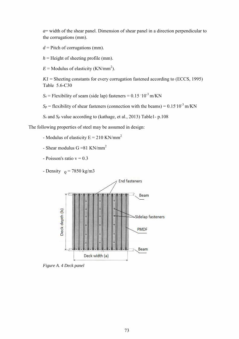
73
a= width of the shear panel. Dimension of shear panel in a direction perpendicular to the corrugations (mm).
d = Pitch of corrugations (mm).
h = Height of sheeting profile (mm).
E = Modulus of elasticity (KN/mm2).
K1 = Sheeting constants for every corrugation fastened according to (ECCS, 1995) Table 5.6-C30
Ss = Flexibility of seam (side lap) fasteners = 0.15 .10-3 m/KN
Sp = flexibility of shear fasteners (connection with the beams) = 0.15.10-3 m/KN
Ss and Sp value according to (kathage, et al., 2013) Table1- p.108
The following properties of steel may be assumed in design:
- Modulus of elasticity E = 210 KN/mm2
- Shear modulus G =81 KN/mm2
- Poisson's ratio v = 0.3
- Density ᵨ = 7850 kg/m3
Figure A. 4 Deck panel

74
Figure A. 5 Deck profile dimensions
All flexibility equations are multiplied by the aspect ratio (b/a) to adjust these flexibility equations according to ECCS Recommendation in line with SDI Manual.
1) Shear deformation of sheet
(b/a)
= [(2*1.73*2400 *(1+0.3)) / (210000*2400*1.22)] (2400/2400) = 0.01778 mm/KN
2) Profile distortion
(b/a)
K = 0.553 (Table 5.6 ECCS Recommendation) = ((203)2.5 * 0.553)/ (210000*1.222.5*2400)) (2400/2400) = 0.405 mm/KN
3) Sheet to beam fasteners flexibility
(b/a)
Sp = 0.15 (mm /KN)
C4 = [( 2* 2400*0.15*203) / (2400)2 ] (2400/2400) C4 = 0.0253 mm/KN
4) Side lap fasteners (seam) flexibility Crimping in the seam fasteners results additional flexibility
(b/a)

75
= [(2) (0.15) (0.15) (4-1)] / [((2) (5) (0.15)] (2400/2400) = 0.09 mm/KN
Finally, the total flexibility in true shear according to ECCS Recommendations
C’= C1 + C2 + C3 + C4 = 0.01778 + 0.405+ 0.0253+ 0.09 = 0.538 mm/KN
The effective shear stiffness for open end deck is:
G’ = 1 / C G’ = (1/ 0.538) (10)3
= 1858 KN/m-rad (OPEN)
The effective shear stiffness for closed end deck is with consideration C2 = 0
C’= C1 + C2 + C3 + C4 = 0.017 + 0 + 0.0253 + 0.09 = 0.133 mm/KN
G’ = (1/ 0.133) (10)3
= 7509 KN/m-rad (CLOSED)
3. Example of calculation shear stiffness using FEM by ABAQUS
The tests that were conducted by ABAQUS focused on the computation of the displacement of the nodes, degree of freedom U1, in the transverse direction. The Sheets were subjected to transverse shear forces (P) that caused a deflection (∆) in the transverse direction as shown in Figure A. 6. . The effective shear stiffness is defined as follows according to (Egilmez, et al., 2007)
Where:
G’= effective shear stiffness (KN/m/rad); = effective shear stress of corrugation sheet (KN/m); ϒ= shear strain; τ'= effective shear stress; P = shear load applied to
the diaphragm; V = effective shear reaction; = panel width; b= span /length of deck
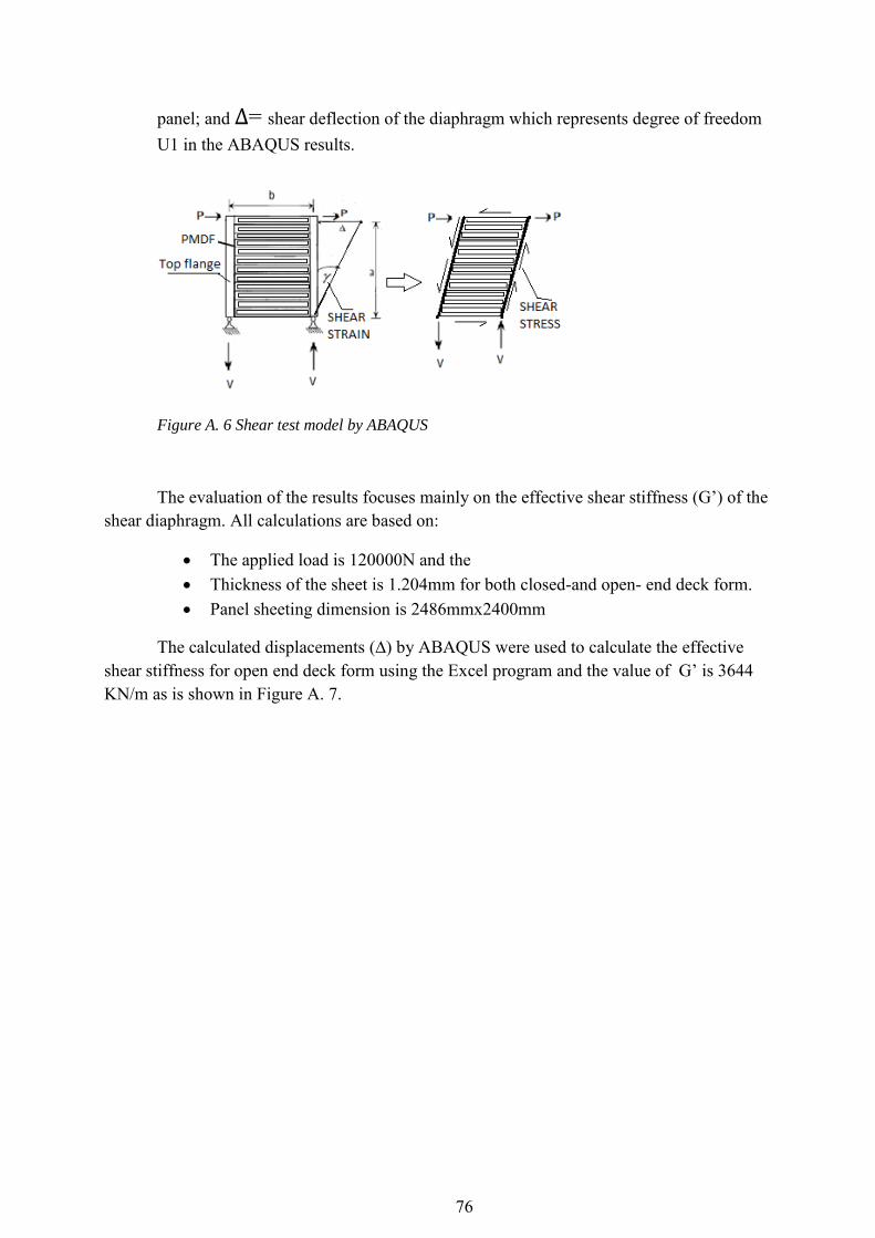
76
panel; and = shear deflection of the diaphragm which represents degree of freedom U1 in the ABAQUS results.
Figure A. 6 Shear test model by ABAQUS
The evaluation of the results focuses mainly on the effective shear stiffness (G’) of the shear diaphragm. All calculations are based on:
The applied load is 120000N and the Thickness of the sheet is 1.204mm for both closed-and open- end deck form. Panel sheeting dimension is 2486mmx2400mm
The calculated displacements (∆) by ABAQUS were used to calculate the effective shear stiffness for open end deck form using the Excel program and the value of G’ is 3644 KN/m as is shown in Figure A. 7.

77
TIME FORCE (P) 2*P Displacement(∆) Span b (mm) Width a (mm) Ƭ (KN/m) ϒ G' KN/m
0 0 0 0 2750 2486 0 0 0
0.001 60 120 -0.00671165 2750 2486 0.05 -2.69978E-06 -17879.36
0.002 120 240 -0.0134233 2750 2486 0.10 -5.39956E-06 -17879.36
0.0035 210 420 -0.0234908 2750 2486 0.17 -9.44924E-06 -17879.34
0.00575 345 690 -0.038592 2750 2486 0.28 -1.55237E-05 -17879.35
0.009125 547.5 1095 -0.0612438 2750 2486 0.44 -2.46355E-05 -17879.36
0.014188 851.25 1702.5 -0.0952215 2750 2486 0.68 -3.83031E-05 -17879.37
0.021781 1306.88 2613.76 -0.146188 2750 2486 1.05 -5.88045E-05 -17879.44
0.033172 1990.31 3980.62 -0.222638 2750 2486 1.60 -8.95567E-05 -17879.34
0.050258 3015.47 6030.94 -0.337313 2750 2486 2.43 -0.000135685 -17879.36
0.075887 4553.2 9106.4 -0.509325 2750 2486 3.66 -0.000204877 -17879.35
0.11433 6859.8 13719.6 -0.767343 2750 2486 5.52 -0.000308666 -17879.36
0.171995 10319.7 20639.4 -1.15437 2750 2486 8.30 -0.000464348 -17879.36
0.258493 15509.6 31019.2 -1.73491 2750 2486 12.48 -0.000697872 -17879.43
0.388239 23294.3 46588.6 -2.60572 2750 2486 18.74 -0.001048158 -17879.36
0.582859 34971.5 69943 -3.91194 2750 2486 28.13 -0.001573588 -17879.36
0.874788 52487.3 104974.6 -5.87127 2750 2486 42.23 -0.002361734 -17879.37
1 60000 120000 -6.71165 2750 2486 48.27 -0.002699779 -17879.36
Figure A. 7 The calculation of effective shear stiffness for open end deck form using Excel
The calculation of effective shear stiffness for closed end deck form is 17879 KN/m as shown in Figure A. 8.
4. Comparison of results from examples
The result of effective shear stiffness for metal deck form 2400mmx2400mm with sheet thickness is 1.204mm according to the calculations in the examples is tabulated below:
Type of deck SDI ECCS FEM
Open end 3852 1858 3644 Closed end 13971 7509 17879 Table A. 2 Comparison of results
TIME FORCE (P) P*2 Displacement (∆) Span f (mm) width a (mm) Ƭ (KN/m) ϒ G' KN/m
0 0 0 0 2400 2486 0 0 0
0.001 60 120 -0.032924 2400 2486 0.048270314 -1.32438E-05 -3644.757624
0.002 120 240 -0.065848 2400 2486 0.096540628 -2.64875E-05 -3644.757624
0.0035 210 420 -0.115234 2400 2486 0.168946098 -4.63532E-05 -3644.757624
0.00575 345 690 -0.189313 2400 2486 0.277554304 -7.61516E-05 -3644.757624
0.009125 547.5 1095 -0.300432 2400 2486 0.440466613 -0.00012085 -3644.751558
0.0141875 851.25 1702.5 -0.467109 2400 2486 0.684835076 -0.000187896 -3644.759574
0.0217813 1306.88 2613.76 -0.717126 2400 2486 1.051391794 -0.000288466 -3644.770933
0.0331719 1990.31 3980.62 -1.09215 2400 2486 1.601214803 -0.00043932 -3644.755757
0.0502578 3015.47 6030.94 -1.65469 2400 2486 2.425961384 -0.000665603 -3644.755211
0.0758867 4553.2 9106.4 -2.49849 2400 2486 3.66307321 -0.001005024 -3644.761436
0.11433 6859.8 13719.6 -3.7642 2400 2486 5.518744972 -0.001514159 -3644.758514
0.171995 10319.7 20639.4 -5.66277 2400 2486 8.302252615 -0.002277864 -3644.753363
0.258493 15509.6 31019.2 -8.51062 2400 2486 12.4775543 -0.003423419 -3644.763836
0.388239 23294.3 46588.6 -12.7824 2400 2486 18.74038616 -0.005141754 -3644.745901
0.582859 34971.5 69943 -19.19 2400 2486 28.13475463 -0.007719228 -3644.762897
0.874788 52487.3 104974.6 -28.8015 2400 2486 42.22630732 -0.011585479 -3644.761558
1 60000 120000 -32.924 2400 2486 48.27031376 -0.013243765 -3644.757624
Figure A. 8 The calculations of effective shear stiffness for closed end deck form using Excel

78
Appendix B
Standard table for deck form 24/4 pattern
Figure B. 1 Standard table that is used to calculate effective shear stiffness G’ for deck form in
building application according to SDI Manual (Luttrell, 1995)with fasteners patterns 24/4.
These tables are used to calculate effective shear stiffness G’ for corrugated deck forms that are used in building application according to SDI Manual (Luttrell, 1995). The tables are arranged showing fastener types and safety factor across the top along with the fastener patterns as defined in Appendix IV in SDI Manual, 1995. The tables present for each metal
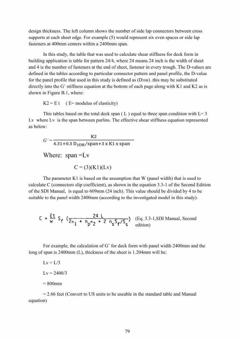
79
design thickness. The left column shows the number of side lap connectors between cross supports at each sheet edge. For example (5) would represent six even spaces or side lap fasteners at 400mm centers within a 2400mm span.
In this study, the table that was used to calculate shear stiffness for deck form in building application is table for pattern 24/4, where 24 means 24 inch is the width of sheet and 4 is the number of fasteners at the end of sheet, fastener in every trough. The D-values are defined in the tables according to particular connector pattern and panel profile, the D-value for the panel profile that used in this study is defined as (D3DR) .this may be substituted directly into the G’ stiffness equation at the bottom of each page along with K1 and K2 as is shown in Figure B.1, where:
K2 = E t ( E= modulus of elasticity)
This tables based on the total deck span ( L ) equal to three span condition with L= 3 Lv where Lv is the span between purlins. The effective shear stiffness equation represented as below:
G’ =
⁄
Where: span =Lv
C = (3)(K1)(Lv)
The parameter K1 is based on the assumption that W (panel width) that is used to calculate C (connectors slip coefficient), as shown in the equation 3.3-1 of the Second Edition of the SDI Manual, is equal to 609mm (24 inch). This value should be divided by 4 to be suitable to the panel width 2400mm (according to the investigated model in this study).
(Eq. 3.3-1,SDI Manual, Second edition)
For example, the calculation of G’ for deck form with panel width 2400mm and the long of span is 2400mm (L), thickness of the sheet is 1.204mm will be:
Lv = L/3
Lv = 2400/3
= 800mm
= 2.66 feet (Convert to US units to be useable in the standard table and Manual equation)

80
For 24/4 pattern ( fasteners in every trough at the sheet ends) and for t (design thickness) is 1.204mm (0.0474 inch) and for stich connectors per span (Lv) equal to 2 From the standard table (Figure B.1) :
K1 = 0.793
K1/4 = 0.19825 (K1 is divided by 4 to be suitable to use for panel width 2400mm).
D3DR = 321
K2 = 1398
Substitution of these values directly in the effective shear stiffness G’ equation as below:
G’ = (1398) / [(4.31) + (0.3) (321)/(2.66) + (3) (0.19825) (2.66)]
= 5816 KN/m

81
Appendix C
ABAQUS Input File
This input file provides a summary sample of the input file that was
used of the finite element analyses. The node numbers of assembly has
been left out from the input file to make this appendix reasonable
short.
*Heading
Closed end deck form 2400mm x 2400mm
Units: Length [mm], Force [N], E-Module [N/mm2]
** Job name: 2400x2400 Model name: Closed end PMDF1
** Generated by: Abaqus/CAE 6.10-1
*Preprint, echo=NO, model=NO, history=NO, contact=NO
**----------------DEFINING THE PARTS--------------
** PARTS
**
*Part, name=BEAM
*End Part
**
*Part, name="closed end sheet1"
*End Part
**---------------ASSEMBLY OF THE PART--------------
**
** ASSEMBLY
Node number of the assembly is left out
**
*Assembly, name=Assembly
**
*Instance, name=beam-1, part=BEAM
0., 0., 514.
*Node
*Nset, nset=_PickedSet10, internal, generate
1, 1008, 1
*Elset, elset=_PickedSet10, internal, generate
1, 923, 1
** Section: BEAM
*Shell Section, elset=_PickedSet10, material=BEAM
20., 5
*End Instance
**
*Instance, name=beam-2, part=BEAM
*Node
*Nset, nset=_PickedSet10, internal, generate
1, 1008, 1
*Elset, elset=_PickedSet10, internal, generate
1, 923, 1
** Section: BEAM
*Shell Section, elset=_PickedSet10, material=BEAM
20., 5

82
*End Instance
**
*Instance, name="closed end sheet1-1", part="closed end sheet1"
*Node
*Nset, nset=_PickedSet8, internal, generate
1, 2706, 1
*Elset, elset=_PickedSet8, internal, generate
1, 2618, 1
** Section: closed end sheet
*Shell Section, elset=_PickedSet8, material="closed end sheet"
1.204, 5
*End Instance
**
*Instance, name="closed end sheet1-1-lin-2-1", part="closed end sheet1"
*Nset, nset=_PickedSet8, internal, generate
1, 2706, 1
*Elset, elset=_PickedSet8, internal, generate
1, 2618, 1
** Section: closed end sheet
*Shell Section, elset=_PickedSet8, material="closed end sheet"
1.204, 5
*End Instance
**
*Instance, name="closed end sheet1-1-lin-3-1", part="closed end sheet1"
*Nset, nset=_PickedSet8, internal, generate
1, 2706, 1
*Elset, elset=_PickedSet8, internal, generate
1, 2618, 1
** Section: closed end sheet
*Shell Section, elset=_PickedSet8, material="closed end sheet"
1.204, 5
*End Instance
**
*Node
*Nset, nset=_PickedSet513, internal, instance=beam-1, generate
1, 1008, 1
*Nset, nset=_PickedSet513, internal, instance=beam-2, generate
1, 1008, 1
*Elset, elset=_PickedSet513, internal, instance=beam-1, generate
1, 923, 1
*Elset, elset=_PickedSet513, internal, instance=beam-2, generate
1, 923, 1
*Nset, nset=_PickedSet555, internal, instance=beam-1
2,
*Nset, nset=_PickedSet555, internal, instance=beam-2
1,
*Nset, nset=_PickedSet556, internal, instance=beam-1
1,
*Nset, nset=_PickedSet556, internal, instance=beam-2
2,
*Nset, nset="Attachment Points-1-Set-1", generate
29, 41, 1
*Nset, nset="Attachment Points-2-Set-1", generate
16, 28, 1
*Nset, nset="Attachment Points-3-Set-1", generate
1, 15, 1

83
*Nset, nset=_PickedSet682, internal, generate
32, 38, 3
*Nset, nset=_PickedSet684, internal, generate
19, 25, 3
*Nset, nset=_PickedSet685, internal, generate
1, 15, 1
*Nset, nset=_PickedSet715, internal
29, 31, 33, 36, 39, 41
*Nset, nset=_PickedSet716, internal
16, 18, 20, 23, 26, 28
*Nset, nset=point, instance=beam-2
2,
--------------INTERACTION DEINITIONS--------------------
*Elset, elset=_INT-ATTSETSURF-ASSY-13_SPOS, internal, instance=beam-1,
generate
427, 497, 1
*Surface, type=ELEMENT, name=_INT-ATTSETSURF-ASSY-13, internal
_INT-ATTSETSURF-ASSY-13_SPOS, SPOS
*Elset, elset=_INT-ATTSETSURF-ASSY-21_SPOS, internal, instance=beam-2,
generate
427, 497, 1
*Surface, type=ELEMENT, name=_INT-ATTSETSURF-ASSY-21, internal
_INT-ATTSETSURF-ASSY-21_SPOS, SPOS
*Elset, elset=_INT-ATTSETSURF-ASSY-22_SPOS, internal, instance=beam-1
1, 2, 3, 4, 5, 6, 7, 8, 9, 10, 11, 12, 13, 14,
15, 16
17, 18, 19, 20, 21, 22, 23, 24, 25, 26, 27, 28, 29, 30,
31, 32
33, 34, 35, 36, 37, 38, 39, 40, 41, 42, 43, 44, 45, 46,
47, 48
49, 50, 51, 52, 53, 54, 55, 56, 57, 58, 59, 60, 61, 62,
63, 64
65, 66, 67, 68, 69, 70, 71, 427, 428, 429, 430, 431, 432, 433,
434, 435
436, 437, 438, 439, 440, 441, 442, 443, 444, 445, 446, 447, 448, 449,
450, 451
452, 453, 454, 455, 456, 457, 458, 459, 460, 461, 462, 463, 464, 465,
466, 467
468, 469, 470, 471, 472, 473, 474, 475, 476, 477, 478, 479, 480, 481,
482, 483
484, 485, 486, 487, 488, 489, 490, 491, 492, 493, 494, 495, 496, 497
*Surface, type=ELEMENT, name=_INT-ATTSETSURF-ASSY-22, internal
_INT-ATTSETSURF-ASSY-22_SPOS, SPOS
*Elset, elset=_INT-ATTSETSURF-ASSY-34_SPOS, internal, instance=beam-1,
generate
427, 497, 1
*Surface, type=ELEMENT, name=_INT-ATTSETSURF-ASSY-34, internal
_INT-ATTSETSURF-ASSY-34_SPOS, SPOS
*Elset, elset=_INT-ATTSETSURF-ASSY-42_SPOS, internal, instance=beam-2,
generate
427, 497, 1
*Surface, type=ELEMENT, name=_INT-ATTSETSURF-ASSY-42, internal
_INT-ATTSETSURF-ASSY-42_SPOS, SPOS
*Elset, elset=_INT-ATTSETSURF-ASSY-43_SPOS, internal, instance=beam-1
1, 2, 3, 4, 5, 6, 7, 8, 9, 10, 11, 12, 13, 14,
15, 16
17, 18, 19, 20, 21, 22, 23, 24, 25, 26, 27, 28, 29, 30,
31, 32

84
33, 34, 35, 36, 37, 38, 39, 40, 41, 42, 43, 44, 45, 46,
47, 48
49, 50, 51, 52, 53, 54, 55, 56, 57, 58, 59, 60, 61, 62,
63, 64
65, 66, 67, 68, 69, 70, 71, 427, 428, 429, 430, 431, 432, 433,
434, 435
436, 437, 438, 439, 440, 441, 442, 443, 444, 445, 446, 447, 448, 449,
450, 451
452, 453, 454, 455, 456, 457, 458, 459, 460, 461, 462, 463, 464, 465,
466, 467
468, 469, 470, 471, 472, 473, 474, 475, 476, 477, 478, 479, 480, 481,
482, 483
484, 485, 486, 487, 488, 489, 490, 491, 492, 493, 494, 495, 496, 497
*Surface, type=ELEMENT, name=_INT-ATTSETSURF-ASSY-43, internal
_INT-ATTSETSURF-ASSY-43_SPOS, SPOS
**
----------------------CREATION OF FASTENERS------------------------
** POINT-BASED FASTENER: Fasteners-1
*Fastener Property, name=Fasteners-1
3.2
*Connector Section, elset=_Fasteners-1_pf_
Beam,
*Fastener, interaction name=Fasteners-1, property=Fasteners-1,
reference node set=_PickedSet715, elset=_Fasteners-1_pf_,
coupling=CONTINUUM, attachment method=FACETOFACE, weighting
method=UNIFORM, adjust orientation=YES, number of layers=1
**
** POINT-BASED FASTENER: Fasteners-2
*Fastener Property, name=Fasteners-2
3.2
*Connector Section, elset=_Fasteners-2_pf_
Beam,
*Fastener, interaction name=Fasteners-2, property=Fasteners-2,
reference node set=_PickedSet682, elset=_Fasteners-2_pf_,
coupling=CONTINUUM, attachment method=FACETOFACE, weighting
method=UNIFORM, adjust orientation=YES, number of layers=2
**
** POINT-BASED FASTENER: Fasteners-3
*Fastener Property, name=Fasteners-3
3.2
*Connector Section, elset=_Fasteners-3_pf_
Beam,
*Fastener, interaction name=Fasteners-3, property=Fasteners-3,
reference node set=_PickedSet716, elset=_Fasteners-3_pf_,
coupling=CONTINUUM, attachment method=FACETOFACE, weighting
method=UNIFORM, adjust orientation=YES, number of layers=1
**
** POINT-BASED FASTENER: Fasteners-4
*Fastener Property, name=Fasteners-4
3.2
*Connector Section, elset=_Fasteners-4_pf_
Beam,
*Fastener, interaction name=Fasteners-4, property=Fasteners-4,
reference node set=_PickedSet684, elset=_Fasteners-4_pf_,
coupling=CONTINUUM, attachment method=FACETOFACE, weighting
method=UNIFORM, adjust orientation=YES, number of layers=2
**
** POINT-BASED FASTENER: Fasteners-5

85
*Fastener Property, name=Fasteners-5
3.2
*Connector Section, elset=_Fasteners-5_pf_
Beam,
*Fastener, interaction name=Fasteners-5, property=Fasteners-5,
reference node set=_PickedSet685, elset=_Fasteners-5_pf_,
coupling=CONTINUUM, attachment method=FACETOFACE, weighting
method=UNIFORM, adjust orientation=YES, number of layers=1
*End Assembly
**
--------------------MATERIALS----------------
** MATERIALS
**
*Material, name=BEAM
*Elastic
210000., 0.3
*Material, name="closed end sheet"
*Elastic
210000., 0.3
*Material, name=stiffner
*Density
0.00785,
*Elastic
210000., 0.3
** --------------------STEP-----------------------------------
**
** STEP: Step-1
**
*Step, name=Step-1
*Static
0.001, 1., 1e-09, 1.
**
** ---------------BOUNDARY CONDITIONS------------------------------
**
** Name: BC-1 Type: Displacement/Rotation
*Boundary
_PickedSet555, 1, 1
_PickedSet555, 2, 2
_PickedSet555, 3, 3
** Name: BC-2 Type: Displacement/Rotation
*Boundary
_PickedSet513, 2, 2
_PickedSet513, 4, 4
_PickedSet513, 6, 6
**
** LOADS
**
** Name: Load-1 Type: Concentrated force
*Cload
_PickedSet556, 1, -60000.
**
** --------------OUTPUT REQUESTS--------------------------
**
*Restart, write, frequency=0
**
** FIELD OUTPUT: F-Output-1
**
*Output, field

86
*Node Output, nset=point
U,
**
** -----------------FIELD OUTPUT: fasteners---------------
**
*Output, field, frequency=99999
*Element Output, elset=_Fasteners-3_pf_, directions=YES
CTF,
**
** HISTORY OUTPUT: point
**
*Output, history
*Node Output, nset=point
U1, U2, U3, UR1, UR2, UR3
**
** HISTORY OUTPUT: fasteners
**
*Output, history, frequency=99999
*Element Output, elset=_Fasteners-3_pf_
CTF1,
*End Step