Dynamic Stall Measurements and Computations for a VR-12
18
Dynamic Stall Measurements and Computations for a VR-12 Airfoil with a Variable Droop Leading Edge P.B. Martin and K.W. McAlister Army / NASA Rotorcraft Division US Army Aviation and Missile Command Aeroflightdynamics Directorate (AMRDEC) Ames Research Center M/S 215-1 Moffett Field, CA 94035-1000 M.S.Chandrasekhara Navy-NASA Joint Institute of Aerospace Sciences Department of Aeronautics and Astronautics Naval Postgraduate School Ames Research Center M/S 260-1 Moffett Field, CA 94035-1000 W. Geissler DLR Institute of Aerodynamics and Flow Technology Bunsenstr 10, Goettingen D-37073, Germany Abstract High density-altitude operations of helicopters with advanced performance and maneuver capabilities have lead to fundamental research on active high-lift system concepts for rotor blades. The requirement for this type of system was to improve the sectional lift-to-drag ratio by alleviating dynamic stall on the retreating blade while simultaneously reducing the transonic drag rise of the advancing blade. Both measured and computational results showed that a Variable Droop Leading Edge (VDLE) airfoil is a viable concept for application to a rotor high-lift system. Results are presented for a series of 2D compressible dynamic stall wind tunnel tests with supporting CFD results for selected test cases. These measurements and computations show a dramatic decrease in the drag and pitching moment associated with severe dynamic stall when the VDLE concept is applied to the Boeing VR-12 airfoil. Test results also show an elimination of the negative pitch damping observed in the baseline moment hysteresis curves. Introduction 1 Compressible dynamic stall places limits on the operational envelope of military class helicopters during maneuvers, high-speed flight, and operations at high density-altitude. These limits are a direct result of the severe unsteady forces and moments that characterize the performance of an airfoil operating through dynamic stall. A breakdown of power components describing a typical transport helicopter shows that the sea level cruise performance is primarily a function of the fuselage and hub drag ratio (see the example calculations in Fig. 1a). At moderate weights and sea level conditions, the rotor airfoils typically operate well within their range of high lift-to-drag. Recent operations in desert and mountainous regions Presented at the American Helicopter Society 59 th Annual Forum, Phoenix, Arizona, May 6 – 8, 2003. This paper is declared a work of the US Government and is not subject to copyright protection in the United States have challenged current rotor designs with effective density-altitudes on the order of 10,000 ft. This can occur either from the requirement to operate at moderate altitudes with temperatures in excess of 100°F, or from the requirement to traverse mountainous terrain. At high density-altitude, the rotor profile power becomes equivalent to the parasite power contribution from the airframe drag at the speed for best range, V br (as shown by Fig. 1). In order to increase range during missions at high density-altitude, it becomes important to improve both the airframe drag and also the rotor lift- to-drag ratio. Two approaches for increasing the rotor lift-to- drag ratio are to decrease the transonic drag rise on the advancing blade and to decrease the stall induced drag rise on the retreating blade. One concept aimed at alleviating both of these flow physics problems is to use an active high-lift system on a portion of the rotor blades. An active high-lift system is required to simultaneously improve the lift-to-drag ratio of the airfoils on the retreating blade without compromising the advancing blade performance. Alternatively, high
Transcript of Dynamic Stall Measurements and Computations for a VR-12

Dynamic Stall Measurements and Computations for aVR-12 Airfoil with a Variable Droop Leading Edge
P.B. Martin and K.W. McAlisterArmy / NASA Rotorcraft Division
US Army Aviation and Missile CommandAeroflightdynamics Directorate (AMRDEC)
Ames Research Center M/S 215-1Moffett Field, CA 94035-1000
M.S.ChandrasekharaNavy-NASA Joint Institute of Aerospace Sciences
Department of Aeronautics and AstronauticsNaval Postgraduate School
Ames Research Center M/S 260-1Moffett Field, CA 94035-1000
W. GeisslerDLR Institute of Aerodynamics and Flow Technology
Bunsenstr 10, Goettingen D-37073, Germany
Abstract
High density-altitude operations of helicopters with advanced performance and maneuver capabilities havelead to fundamental research on active high-lift system concepts for rotor blades. The requirement for this type ofsystem was to improve the sectional lift-to-drag ratio by alleviating dynamic stall on the retreating blade whilesimultaneously reducing the transonic drag rise of the advancing blade. Both measured and computational resultsshowed that a Variable Droop Leading Edge (VDLE) airfoil is a viable concept for application to a rotor high-liftsystem. Results are presented for a series of 2D compressible dynamic stall wind tunnel tests with supporting CFDresults for selected test cases. These measurements and computations show a dramatic decrease in the drag andpitching moment associated with severe dynamic stall when the VDLE concept is applied to the Boeing VR-12airfoil. Test results also show an elimination of the negative pitch damping observed in the baseline momenthysteresis curves.
Introduction
1Compressible dynamic stall places limits onthe operational envelope of military class helicoptersduring maneuvers, high-speed flight, and operations athigh density-altitude. These limits are a direct result ofthe severe unsteady forces and moments thatcharacterize the performance of an airfoil operatingthrough dynamic stall. A breakdown of powercomponents describing a typical transport helicoptershows that the sea level cruise performance is primarilya function of the fuselage and hub drag ratio (see theexample calculations in Fig. 1a). At moderate weightsand sea level conditions, the rotor airfoils typicallyoperate well within their range of high lift-to-drag.Recent operations in desert and mountainous regions
Presented at the American Helicopter Society 59th
Annual Forum, Phoenix, Arizona, May 6 – 8, 2003.This paper is declared a work of the US Government and isnot subject to copyright protection in the United States
have challenged current rotor designs with effectivedensity-altitudes on the order of 10,000 ft. This canoccur either from the requirement to operate atmoderate altitudes with temperatures in excess of100°F, or from the requirement to traverse mountainousterrain. At high density-altitude, the rotor profile powerbecomes equivalent to the parasite power contributionfrom the airframe drag at the speed for best range, Vbr
(as shown by Fig. 1). In order to increase range duringmissions at high density-altitude, it becomes importantto improve both the airframe drag and also the rotor lift-to-drag ratio.
Two approaches for increasing the rotor lift-to-drag ratio are to decrease the transonic drag rise on theadvancing blade and to decrease the stall induced dragrise on the retreating blade. One concept aimed atalleviating both of these flow physics problems is to usean active high-lift system on a portion of the rotorblades. An active high-lift system is required tosimultaneously improve the lift-to-drag ratio of theairfoils on the retreating blade without compromisingthe advancing blade performance. Alternatively, high
performance transonic airfoils could be used on theouter regions of the rotor blade. The poor high-liftperformance of this type of airfoil could be overcomeby the use of a drooping leading edge over theretreating side of the rotor disc.
In addition to the performance improvements,an active high-lift system might present a practicalsolution to common aeroelastic problems leading toexcessive loads and vibration. Coupled with the elasticrotor blade motion, the onset of dynamic stall createslarge unsteady pitch link loads causing vibration, rapidlocalized changes in blade lift and acoustic signatures,and negative torsional damping that may lead toaeroelastic instabilities. The sources of these 3Dunsteady aerodynamic phenomenon occurring on fullscale rotor blades are based in part on the fundamentalflow physics measured in 2D oscillating airfoil windtunnel tests. In response to emerging US Armyrequirements for transformation to a new generation ofhighly maneuverable, high speed rotorcraft, continuedefforts are aimed at a better understanding of dynamicstall onset and control through experimental andnumerical studies. This paper presents results from ajoint US Army / DLR Goettingen cooperative dynamicstall control research program.
Compressible dynamic stall control hasalready been demonstrated on a symmetric NACA 0012airfoil using the dynamically deforming leading edge(DDLE) airfoil concept (Ref. 1). In this design, theairfoil leading edge curvature was dynamically variedby as much as 320% by retracting its nose a very small(of the order of 1% chord) distance. However, theconcomitant gross potential flow changes resulted in adramatically improved airfoil instantaneous pressuredistribution, which favorably influences the dynamicstall vorticity field and enables control (Ref. 1).Dynamic stall control has also been achieved using aslatted helicopter airfoil at Mach numbers of up to 0.4(Ref. 2). In this study, different leading-edge slats wereshown to be effective in preventing the formation of thedynamic stall vortex on the main element of the airfoil.The natural bleed flow through the slat-airfoil slot wassufficient to produce the desired effects. Although boththe DDLE airfoil and the slatted airfoils were proven tobe successful in delaying stall onset, the need tomaintain a highly flexible leading edge surface in theformer and the drag of the slat on the rotor advancingside with the latter approach were deemed somewhatrestrictive (Ref. 3).
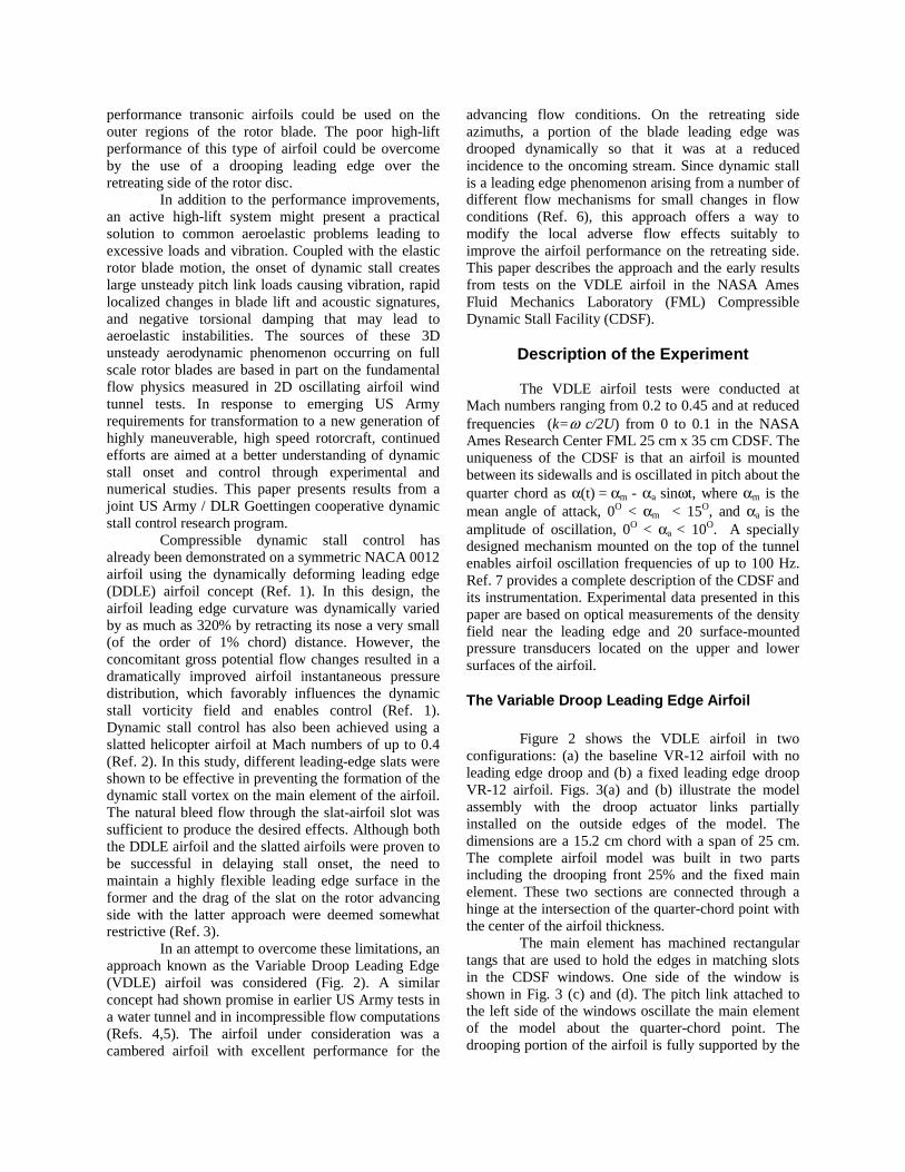
In an attempt to overcome these limitations, anapproach known as the Variable Droop Leading Edge(VDLE) airfoil was considered (Fig. 2). A similarconcept had shown promise in earlier US Army tests ina water tunnel and in incompressible flow computations(Refs. 4,5). The airfoil under consideration was acambered airfoil with excellent performance for the
advancing flow conditions. On the retreating sideazimuths, a portion of the blade leading edge wasdrooped dynamically so that it was at a reducedincidence to the oncoming stream. Since dynamic stallis a leading edge phenomenon arising from a number ofdifferent flow mechanisms for small changes in flowconditions (Ref. 6), this approach offers a way tomodify the local adverse flow effects suitably toimprove the airfoil performance on the retreating side.This paper describes the approach and the early resultsfrom tests on the VDLE airfoil in the NASA AmesFluid Mechanics Laboratory (FML) CompressibleDynamic Stall Facility (CDSF).
Description of the Experiment
The VDLE airfoil tests were conducted atMach numbers ranging from 0.2 to 0.45 and at reducedfrequencies (k=ω c/2U) from 0 to 0.1 in the NASAAmes Research Center FML 25 cm x 35 cm CDSF. Theuniqueness of the CDSF is that an airfoil is mountedbetween its sidewalls and is oscillated in pitch about thequarter chord as α(t) = αm - αa sinωt, where αm is themean angle of attack, 0O < αm < 15O, and αa is theamplitude of oscillation, 0O < αa < 10O. A speciallydesigned mechanism mounted on the top of the tunnelenables airfoil oscillation frequencies of up to 100 Hz.Ref. 7 provides a complete description of the CDSF andits instrumentation. Experimental data presented in thispaper are based on optical measurements of the densityfield near the leading edge and 20 surface-mountedpressure transducers located on the upper and lowersurfaces of the airfoil.
The Variable Droop Leading Edge Airfoil
Figure 2 shows the VDLE airfoil in twoconfigurations: (a) the baseline VR-12 airfoil with noleading edge droop and (b) a fixed leading edge droopVR-12 airfoil. Figs. 3(a) and (b) illustrate the modelassembly with the droop actuator links partiallyinstalled on the outside edges of the model. Thedimensions are a 15.2 cm chord with a span of 25 cm.The complete airfoil model was built in two partsincluding the drooping front 25% and the fixed mainelement. These two sections are connected through ahinge at the intersection of the quarter-chord point withthe center of the airfoil thickness.
The main element has machined rectangulartangs that are used to hold the edges in matching slotsin the CDSF windows. One side of the window isshown in Fig. 3 (c) and (d). The pitch link attached tothe left side of the windows oscillate the main elementof the model about the quarter-chord point. Thedrooping portion of the airfoil is fully supported by the

hinge. The hinge axis also passes through the quarter-chord point (see Fig. 3). The hinge-shaft is hollow (forcarrying instrumentation leads) and protrudes out of theCDSF windows. It is connected to drive linkages (seeFig. 3) on either side of the test section. If theselinkages are anchored to the oscillating windows, afixed leading edge droop angle (relative to the mainelement) results through the oscillation cycle, as in Fig.3(c). Moving the location of the anchor point on theoscillating windows changes the magnitude of thedroop angle. A continuously variable droop results ifthe anchor point is fixed to the tunnel sidewalls, as inFig. 3(d). The droop value varies as δle= α during theoscillation cycle.
In the variable droop mode of operation, theleading edge remains at a fixed orientation in the windtunnel coordinate system, while the main elementchanges its incidence through the oscillation cycle.Following the standard convention for high-liftsystems, both the angle of attack and the leading edgedroop angle are defined with respect to the chordline ofthe main element. This design proved to bemechanically simple and very reliable for highfrequency oscillations. It is important to note thatapplication of this concept to a rotor blade requires acompletely different design. Additional details of theexperiment are reported in Ref. 8.
Numerical Procedure
The numerical code used for the presentcalculations is described in Ref. 9. This code is basedon the approximate factorization implicit methodologyoriginally developed by Beam and Warming (Ref. 10).A special feature of the code is the capability to usedeformable grids. In a space fixed frame of referencethe airfoil was allowed to oscillate about a prescribedmean incidence and, in addition, the deformation of theairfoil leading edge was realized. In arbitrary cases thedeformation takes place within a prescribed timewindow of the oscillation cycle. In Ref. 11 this timewindow has been implemented between the meanincidence up-stroke and the mean incidence down-stroke with a maximum droop angle of 10o at themaximum incidence of the airfoil motion. For the lowerincidence part of the cycle the airfoil has its basis shape(VR12).
Different from Ref. 11, the time window in thepresent investigation was extended over the wholeperiod of oscillation: the droop angle was zero at theminimum incidence and was continuously increased toa maximum droop angle corresponding to themaximum incidence of the airfoil. This specialarrangement lead to a 25% leading edge flap of theairfoil which did not move whereas the rear 75% of theairfoil was rotated about the quarter chord axis
according to the prescribed incidence variation. Thisspecial nose-droop device has been realized on acorresponding wind tunnel model (see Fig. 2). Thenumerical treatment of this case was, however, identicalto the more general problem described in Ref. 11.
In order to sufficiently resolve the complexunsteady flow of an oscillating airfoil under dynamicstall conditions, a rather fine grid with 385x81 gridpoints was used. With this fine grid y+ of the first gridline off the airfoil surface was kept at the order of one.Of great concern was the time resolution of thecalculation. In the present numerical calculations asmany as 105 time steps per period were used with atotal of 2 periods for sufficient periodic convergence.For the present calculations the Spalart-Allmaras (Ref.12) one equation turbulence model was used. Allcalculations were assumed fully turbulent.
Results and Discussion
The use of both experimental measurementsand numerical computations enables a more completedescription of a given aerodynamic test case. Theseresults represent a first comparison of the numericalstudy with measurements. Using this first level ofcomparison, several issues are currently underinvestigation including the effects of wind tunnel wallcorrections in unsteady experiments and the modelingof the migration of transition during the oscillationcycle.
Computational Results
One of the key results of this study is that thegeneral trends in measured and predicted performanceagree for similar test cases, as shown in Tables 1 and 2.Both the test data and the CFD show a slight reductionin maximum lift, a large reduction in maximum drag,and a significant reduction in peak pitching moment. Adirect comparison between the CFD results and themeasurements is shown in Fig. 4 for two different Machnumbers of M = 0.3 and M = 0.4 at a single reducedfrequency of k = 0.1. These conditions arerepresentative of a typical retreating blade stallmeasured on a UH-60A BlackHawk helicopter (Ref.13). While the lift, drag, and moment curves showqualitative agreement with the measured cases, theincremental changes between the baseline case and thevariable droop case appear to be in agreement (see Fig.4 and Tables 1 – 2). In general, the computations overpredict the benefit of the VDLE for M=0.3, but moreclosely match the measured trends for M=0.4.
A comparison of the instantaneous pressuredistributions during the cycle is shown for the M=0.3baseline and VDLE cases in Fig. 5. For the baselinecase, it appears that there is a ∆α=2º stall delay in the
computations (Figs. 5a and 5b) which may be attributedto wind tunnel wall interference effects not accountedfor in the computations. However, the details of thestall, once initiated, appear to match the measurementsin terms of the vortex footprint (Fig. 5b). For the VDLEcase, the numerical results appear different from themeasurements around the hinge line (Figs. 5c-d). Thereappears to be either more boundary layer thickening ormild separation aft of the hinge line observed in themeasurements, but not captured in the numericalanalysis. One explanation of these discrepancies may bedue to the assumption of fully turbulent flow. Themeasured transition locations in Ref. 14 show theupstream movement of transition prior to dynamic stall.Future calculations will take into account a transitionmodel and try to solve this problem.
Some of the key features of the variable droopresults are the reduced drag and peak pitching momentthat occur during the dynamic stall. As a result, theconcept appears to not only improve the lift-to-dragratio at high Cl, but also reduces the undesirablepitching moment by reducing the severity of themoment stall. One of the mechanisms for theperformance gain of the VDLE is clearly shown by theCFD pressure field in Fig. 6, where the low pressuresignature of the dynamic stall vortex has been reducedby the drooped leading edge. The CFD results in Fig. 7show the Mach number distribution around the leadingedge. This figure demonstrates how the VDLE conceptalleviates the supersonic pocket responsible for shockboundary layer separation.
M=0.3 ∆Cl max ∆Cd max -∆Cm min
CFD -0.22(11%) -0.49(72%) -0.32(68%)EXP -0.14(8%) -0.35(63%) -0.11(31%)
Table 1. Difference between baseline and VDLEperformance at M = 0.3, k = 0.10
M=0.4 ∆Cl max ∆Cd max -∆Cm min
CFD -0.20(10%) -0.39(56%) -0.20(43%)EXP -0.15(8%) -0.36(63%) -0.15(37%)
Table 2. Difference between baseline and VDLEperformance at M = 0.4, k = 0.10
Flow Visualization
Using the technique of Point DiffractionInterferometry (Ref. 15), flow visualization imageswere acquired for several test cases in Fig. 8. At higherMach numbers the mechanism for dynamic stall on theVR-12 airfoil changes from a trailing edge separation toa shock induced leading edge separation (as shown bythe PDI images in Fig. 8). As a result, since the
successful application of active stall control to a rotorrequires a technique that works over a range of Machnumbers, two different stall mechanisms must beaddressed.
Measured Results for M = 0.3 k = 0.10
The measured pressure contours during theupstroke for the M = 0.30 , k = 0.10 case are shown inFig. 9 for the baseline (zero droop) configuration and inFig. 10 for the variable droop configuration. For thebaseline case, Fig. 9 has a peak suction pressurereaching just beyond the critical value. As a result,severe adverse pressure gradients form near the airfoilleading edge. Just after the angle of attack where themagnitude of the adverse pressure gradient reaches amaximum, a stagnation region of separated flow occursnear the trailing edge and moves forward. This subtleflow feature of trailing edge separation is thenaccompanied by the formation of a dynamic stall vortexnear 30% chord. The presence of the vortex is markedin Fig. 9 by the low pressure ridge moving downstreamwith increasing angle of attack.
With the formation and convection of thevortex along the airfoil chord, the suction peakcollapses in two phases. During the formation of thevortex, the peak collapses rapidly to approximately halfof its final value. Following this first phase, the vortexconvection is then marked by a gradual roll-off of thesuction peak to its final value at the top of the upstroke.This sequence of events (initiated by trailing edgeseparation and followed by the formation andconvection of the vortex) creates the double peak in thelift coefficient shown in Fig. 11 prior to the stall angle.
In comparison, Fig. 10 indicates that variabledroop alleviates the severe adverse pressure gradientsassociated with the build-up of a large leading edgesuction peak. A mild trace of a weak stall vortex stillappears; however, the collapse of the leading edgesuction peak observed in Fig. 9 does not occur with thevariable droop case in Fig. 10.
The associated lift, drag, and pitching momentcurves are shown in Figs. 11-13 for zero droop, fixeddroop, and variable droop. Also shown, are the resultsfor a quasi-static case with zero droop at low reducedfrequency on the order of k ≈ 0.002. In terms of the liftbehavior, the fixed droop case increases the zero liftangle but maintains the same lift curve slope (asexpected based on thin airfoil theory). The fixed droopsoftens the stall and removes the double peak found inthe baseline lift curve; however, the maximum liftcoefficient is slightly reduced. This can be attributed toweakening the dynamic stall vortex and therefore theinduced lift. The lift behavior of the variable droop casefollows the baseline at low angle of attack and thentransitions to the fixed droop case near 10 deg angle of

attack. This is the angle where the variable droop isequal to the fixed droop of 10 deg. As a result, the zerolift angle is not changed significantly, but the lift curveslope is reduced. At the high angles, the variable droopreaches δle=20 deg, and stall is alleviated, but again thedrooped leading edge causes a reduction in themaximum lift coefficient. Another possible source forthe reduced Clmax could be the influence of the hingeline on the boundary layer; however, the numericalresults predicted the same reduction while assuming asmooth transition with no hinge line in thecomputational grid.
In terms of the drag curves in Fig. 12, the fixeddroop reduces the peak drag to near the baseline quasi-static value. The drag is reduced over the high angle ofattack range for both the fixed and variable droop cases.An important result is that the variable droop casereduces the peak pressure drag levels by a factor ofnearly three (as predicted by the numerical results). Atlow angles of attack, the drag penalty of the fixed droopcase increases the α=0 drag by a factor of three (seeFig. 12). This is the same penalty found for slottedairfoils applied to rotor blades (Ref. 3).
Another advantage of the variable droopconcept is the reduction of the peak pitching momentduring stall shown in Fig. 13. While the fixed droopcase shows a slight reduction, the variable droop caserestores the peak moment coefficient to near the quasi-static value. In addition, there is a large pitchingmoment penalty at low angles of attack caused by thefixed droop case (see Fig. 13). The large drag andmoment penalties associated with fixed droop at lowangles (Figs. 12-13) illustrate the need for a variabledroop instead of fixed droop. Clearly, fixed droopwould cause a large performance penalty on theadvancing side of the rotor disk.
A key result that was not completely predictedby the numerical analysis is shown in Fig. 14. Thenegative pitch damping that occurs in the baselinemoment curve was completely eliminated by thevariable droop. The CFD results show a slight reductionin the amount of negative damping, but a cross-overstill occurs in Fig. 4. It is interesting to note this resultwas predicted by earlier numerical computations usingthe ZETA code in support of water tunnel testing of thesame VDLE concept (Ref. 5) applied to a VR-12. As aresult, this concept shows promise with regard topreventing common rotor blade aeroelastic instabilitiesassociated with pitch damping. In addition, the largereduction in drag may also reduce the severity of lead-lag instabilities that are excited by the impulsive dragforce attributed to severe dynamic stall. Onerecommendation from this study is that the VDLEairfoil measurements be used in a comprehensiveanalysis to study some of these aeroelastic stabilityissues in more detail.
Measured Results for M = 0.4 k = 0.10
As shown by the flow visualization images inFigs. 8f and 8g, the change in Mach number fromM=0.3 to M=0.4 alters the mechanism causingboundary layer separation. The VR-12 airfoil switchesfrom a trailing edge stall to a leading-edge, shock-induced stall. A successful flow control technique mustbe able to cope with both trailing edge and leading edgeseparation. For the M=0.4 case, the footprint of theshock (visible in Fig. 8f) appears in the pressuredistribution of Fig. 15 prior to the formation of the stallvortex. This additional flow feature is not observed inthe M=0.3 pressure distribution in Fig. 9. The result ofusing the VDLE concept prevents the formation of asupersonic pocket near the leading edge, and so noshock boundary layer interaction occurs in Fig. 16. Thesignature of the stall vortex is greatly reduced, and thereis only a slight roll-off of the peak suction pressure.
The corresponding forces and moments for theM=0.4 case are shown in Figs. 17-19. In contrast to theM=0.3 case, the VDLE maximum lift is greater than thefixed droop in Fig. 17. Another difference is that thepeak drag coefficient is only slightly reduced for theVDLE compared to fixed droop in Fig. 18. Both thefixed and variable droop cases show a large reductionin the peak drag, as was observed for the M=0.3 case(Fig. 12). The major difference between the M=0.3 andM=0.4 results is that the 10° fixed droop reduced themagnitude of the peak pitching moment more than theVDLE in Fig. 19. This indicates that the full 20° drooprange of the VDLE may be excessive for the higherMach number case. The VDLE does, however,eliminate the negative torsional damping that is onlyslightly changed by the fixed droop. As in the M=0.3case, the low angle of attack drag and moment penaltiesare observed for the fixed droop.
Application to Rotor Stall Alleviation
According to Ref. 16, it is the ratio of themaximum lift to both the minimum pitching momentand the maximum drag that determines the relativemerit of a rotor stall alleviation concept. Using adynamic stall function for both the pitching momentand the drag (as in Ref. 16), the relative merits of theVDLE airfoil are summarized in Fig. 20. Themeasurements shown in this figure cover a range ofreduced frequency and Mach number representative ofmoderate retreating blade stall (Ref. 13). As shown byFig. 20, the general trend of the VDLE is to reduce themagnitude of the peak drag and pitching moment whileonly slightly reducing the maximum lift coefficient.
Future work on application of this concept to arotor includes the identification of optimum droopschedules, chordwise hinge location, and radial location

of the drooping section. The mechanical design andintegration of a variable droop leading edge airfoil intoa full-scale rotor blade remains a challenge, howeverthese results provide motivation for further research anddevelopment of this concept.
Conclusions
(1) An effective compressible dynamic stall controltechnique using the VDLE airfoil has been presented inthis paper. Both flow visualization and unsteadypressure measurements over a VDLE airfoil wereobtained for a wide range of flow conditions and airfoilconfigurations. These include the baseline no-droopairfoil, the fixed-droop airfoil, and the VDLE airfoil.(2) Preliminary results clearly demonstrate the ability ofthe VDLE airfoil to control the dynamic stall processfor different stall onset mechanisms, while avoiding thelow angle of attack penalties associated with other high-lift systems. Significant decreases in the peak drag andpitching moment coefficients were found in both themeasurements and CFD, thus validating this flowcontrol concept.(3) The measured results showed an additional benefitwhere the negative torsional damping caused bydynamic stall was completely eliminated by thevariable droop leading edge concept.(4) For the baseline case, it appears there is a ∆α=2ºstall delay in the computations at M=0.3, and a slightdifference in the flow over the hinge line. While thecomputed lift, drag, and moment curves showqualitative agreement with the measured cases, theincremental changes between the baseline case and thevariable droop case appear to be in quantitativeagreement.
Acknowledgments
This work was performed under the US Army/ Germany Memorandum of Understanding (MOU)with K. McAlister and W. Geissler as the principalinvestigators. The numerical work was performed byDLR and the experiments were conducted by the USArmy. The VDLE concept was developed by CheeTung. Larry Carr and Mike Wilder initiated work on thewind tunnel model design and data acquisition system.
References
[1] Chandrasekhara, M.S., Wilder, M.C., and Carr, L.W., “Compressible Dynamic Stall Control UsingDynamic Shape Adaptation,” AIAA Paper 99-0655,1999.[2] Carr, L.W., Chandrasekhara, M.S., Wilder, M.C.,and Noonan, K.W., “Effect of Compressibility onSuppression of Dynamic Stall Using a Slotted Airfoil,”
(AIAA Paper 98-0332), Journal of Aircraft, Vol. 38,No. 2, pp.296-309, March-April. 2001.[3] Yeo, H., and Lim, J. W., “Application of a SlottedAirfoil for UH-60A Helicopter Performance,” AHS:Aerodynamics, Acoustics and Test and EvaluationTechnical Specialist Meeting, San Francisco, CA,January 23-25, 2002.[4] Yu, Y.H., Lee, S., McAlister, K.W., Tung, C. , andWang, C.M., “Dynamic Stall Control for AdvancedRotorcraft Application,” AIAA Journal, Vol. 33, No. 2,pp. 289-295.[5] Lee, S., McAlister, K., and Tung, C.,“Characteristics of Deformable Leading Edge for HighPerformance Rotor,” AIAA 11th AppliedAerodynamics Conference, August 9-11, Monterey CA,1993.[6] Chandrasekhara, M.S., Wilder, M.C., and Carr, L.W., “On the Competing Mechanisms of CompressibleDynamic Stall,” (AIAA Paper 96-1953), AIAA Journal,Vol. 36, No. 3, March 1998, pp. 387-393.[7] Carr, L.W., and Chandrasekhara, M.S., “Design andDevelopment of a Compressible Dynamic StallFacility,” Journal of Aircraft, Vol. 29, No. 3, May-June1992, pp. 314-318.[8] M.S.Chandrasekhara, Martin, P.B., Tung, C.,“Compressible Dynamic Stall Using a Variable DroopLeading Edge Airfoil,” (AIAA Paper 2003-0048),2003.[9] Geissler, W. “Verfahren in der InstationärenAerodynamik (Methods in UnsteadyAerodynamics) ,” DLR-FB 93-21 , 1993.[10] Beam,R., and Warming,R.F., “An ImplicitFactored Scheme for the Compressible Navier-StokesEquations,” AIAA J. Vol.16, No.4 (April 1978).[11] Geissler, W., and Trenker,M., “NumericalInvestigation of Dynamic Stall Control by a Nose-Droop Device,” AHS: Aerodynamics, Acoustics andTest and Evaluation Technical Specialist Meeting, SanFrancisco, CA, January 23-25, 2002.[12] Spalart, P., and Allmaras, S.R., “A One EquationTurbulence Model for Aerodynamic Flows,”AIAA-paper 92-0439, January 1992.[13] Bousman, W. G., “Airfoil Design and RotorcraftPerformance,” American Helicopter Society, 58th
Annual Forum, Montreal Canada, June 11-13, 2002.[14] Chandrasekhara, M. S., and Wilder, M. C., “HeatFlux Gage Studies of Compressible Dynamic Stall,”(AIAA Paper 2002-0291) to appear in AIAA Journal.[15] N.Brock, M.S.Chandrasekhara, and L.W.Carr, “AReal Time Interferometry System for Unsteady FlowMeasurements,” ICIASF’91 RECORD, IEEEPublication 91CH3028-8, pp. 423-430.[16] Bousman, W. G. , “Evaluation of Airfoil DynamicStall Characteristics for Maneuverability,” 26th
European Rotorcraft Forum, The Hague, Netherlands,Sept. 26-29, 2000.
Fig. 1. Power breakdown estimate at (a) sea level and at (b) 10,000ft density altitude.
Fig. 2. Baseline VR-12 airfoil (a) baseline airfoil (b) drooped leading edge.
0.25c(a)
(b)
(a) (b)

Fig. 3. VDLE airfoil and wind tunnel mounting configurations.
(a) VDLE airfoil model with leading edge detached(b) VDLE airfoil with leading edge assembled(c) Leading edge cam mounted to rotating frame of reference for fixed droop(d) Leading edge cam mounted to fixed frame of reference for variable droop
(a) (b)
(c) (d)

Fig. 4: CFD results compared to measurements.
(a) M = 0.3 , k = 0.10 baseline droop(b) M = 0.4 , k = 0.10 baseline droop(c) M = 0.3 , k = 0.10 variable droop(d) M = 0.4 , k = 0.10 variable droop
(a) (b)
(c) (d)
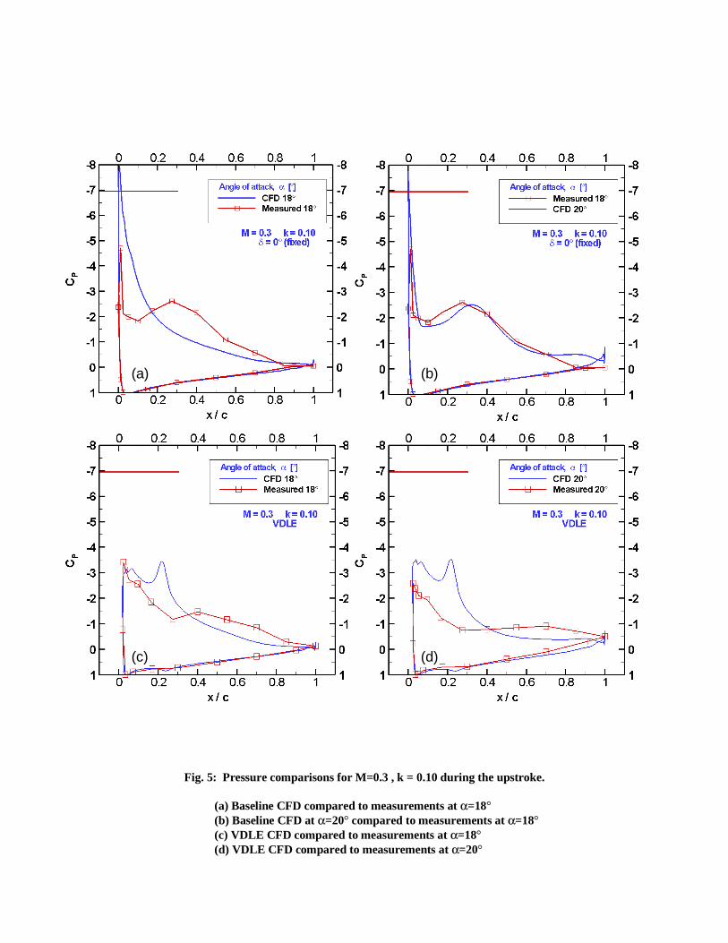
Fig. 5: Pressure comparisons for M=0.3 , k = 0.10 during the upstroke.
(a) Baseline CFD compared to measurements at α=18°(b) Baseline CFD at α=20° compared to measurements at α=18°(c) VDLE CFD compared to measurements at α=18°(d) VDLE CFD compared to measurements at α=20°
(a) (b)
(c) (d)

Fig. 6: CFD Pressure contours at 19.7° (upstroke).
(a) baseline (no droop)(b) variable droop leading edge
Fig. 7: CFD Mach contours at 18.4° during upstroke.
(a) baseline (no droop)
(b) variable droop leading edge
(a)
(b)
(a)
(b)

Fig. 8: Point Diffraction Interferometry images of baseline VR-12 dynamic stall during the upstroke.
(a) M = 0.3, k = 0.10, α=12.5 deg(b) M = 0.3, k = 0.10, α=17.0 deg(c) M = 0.3, k = 0.10, α=18.0 deg(d) M = 0.3, k = 0.10, α=20.0 deg(e) M = 0.4, k = 0.10, α= 9.8 deg(f) M = 0.4, k = 0.10, α=12.5 deg(g) M = 0.4, k = 0.10, α=14.0 deg(h) M = 0.3, k = 0.10, α=15.0 deg

Fig. 9: Pressure contours during the upstroke
M = 0.3 , k = 0.10 , zero droop baseline.
Fig. 10: Pressure contours during the upstroke
M = 0.3 , k = 0.10 , variable droop case.

Fig. 11: Lift coefficient integrated from measured pressure distributions.
Fig. 12: Drag coefficient integrated from measured pressure distributions.

Fig. 13: Moment coefficient integrated from measured pressure distributions.
Fig. 14: Elimination of negative pitch damping.

Fig. 15: Pressure contours during the upstroke
M = 0.4 , k = 0.10 , zero droop baseline.
Fig. 16: Pressure contours during the upstroke
M = 0.4 , k = 0.10 , variable droop case.

Fig. 17: Lift coefficient integrated from measured pressure distributions.
Fig. 18: Drag coefficient integrated from measured pressure distributions.

Fig. 19: Moment coefficient integrated from measured pressure distributions.
Fig. 20: Bousman’s dynamic stall function (Ref. 15) for the VR-12 with and without variable droop (meanangle 10 deg , k=0 to 0.1 , and M = 0.2 to 0.4).