
Dynamic modeling of trawl fishing gear components
12
79 A numerical model has been developed to calculate the resistance of the different components of a trawling gear, by deduction of the drag and lift components. For this purpose, mathematical models have been considered for all the elements, such as trawl cables, floats, doors, and the net itself. e most important contribution of this numerical model is that the action of forces upon different elements permits modifying the geometric configuration of the complete set with a mutual accommodation of resistance and geometry, simulating the actual dynamics, where forces and geometry converge toward an equilibrium state. Some results obtained from actual fishing gear with data obtained from sensors during sea trials are used to compare the results of the simulator. El Grupo de Investigaciones Pesqueras del Instituto de Mecánica de los Fluidos e Ingeniería Ambiental (IMFIA) de la Facultad de Ingeniería en Uruguay ha desarrollado un modelo numérico que permite calcular la resistencia de los distintos componentes de un aparejo de pesca de arrastre, deduciendo las componentes que corresponden al arrastre (drag) y la sustentación (lift). Para ello, se han adoptado modelos matemáticos de todos los elementos tales como los cables de arrastre, flotadores, portones y la propia red. En este modelo numérico, la acción de las fuerzas sobre los distintos elementos modifican la configuración geométrica del conjunto con lo cual se produce un acomodamiento resistencia – geometría, reproduciendo la simulación del estado real, donde las fuerzas y la configuración convergen hacia una condición de equilibrio. Al final del trabajo, se presentan algunos resultados obtenidos en aparejos de pesca reales con datos obtenidos de sensores en pruebas de mar por medio de los cuales se pueden comparar los resultados del simulador. Key words: Nets, fishing, numeric model, net gear. Palabras claves: redes, pesca, modelación numérica, aparejo. Jorge Freiria Pereira 1 Abstract Resumen 1 Facultad de Ingeniería, CP 11300 Montevideo, Montevideo, Uruguay. e-mail: jfreiria@fing.edu.uy Modelación Dinámica de componentes de Aparejos de Pesca de Arrastre Date Received: October 24th, 2010 - Fecha de recepción: 24 de Octubre de 2010 Date Accepted: January 17th, 2012 - Fecha de aceptación: 17 de Enero de 2012 Dynamic modeling of trawl fishing gear components Ship Science & Technology - Vol. 6 - n.° 11 - (57-65) July 2012 - Cartagena (Colombia) brought to you by CORE View metadata, citation and similar papers at core.ac.uk provided by SHIP Science & Technology (E-Journal) / Ciencia y tecnología de buques (Cotecmar)
Transcript of Dynamic modeling of trawl fishing gear components
79
A numerical model has been developed to calculate the resistance of the different components of a trawling gear, by deduction of the drag and lift components. For this purpose, mathematical models have been considered for all the elements, such as trawl cables, floats, doors, and the net itself.
The most important contribution of this numerical model is that the action of forces upon different elements permits modifying the geometric configuration of the complete set with a mutual accommodation of resistance and geometry, simulating the actual dynamics, where forces and geometry converge toward an equilibrium state. Some results obtained from actual fishing gear with data obtained from sensors during sea trials are used to compare the results of the simulator.
El Grupo de Investigaciones Pesqueras del Instituto de Mecánica de los Fluidos e Ingeniería Ambiental (IMFIA) de la Facultad de Ingeniería en Uruguay ha desarrollado un modelo numérico que permite calcular la resistencia de los distintos componentes de un aparejo de pesca de arrastre, deduciendo las componentes que corresponden al arrastre (drag) y la sustentación (lift). Para ello, se han adoptado modelos matemáticos de todos los elementos tales como los cables de arrastre, flotadores, portones y la propia red. En este modelo numérico, la acción de las fuerzas sobre los distintos elementos modifican la configuración geométrica del conjunto con lo cual se produce un acomodamiento resistencia – geometría, reproduciendo la simulación del estado real, donde las fuerzas y la configuración convergen hacia una condición de equilibrio. Al final del trabajo, se presentan algunos resultados obtenidos en aparejos de pesca reales con datos obtenidos de sensores en pruebas de mar por medio de los cuales se pueden comparar los resultados del simulador.
Key words: Nets, fishing, numeric model, net gear.
Palabras claves: redes, pesca, modelación numérica, aparejo.
Jorge Freiria Pereira 1
Abstract
Resumen
1 Facultad de Ingeniería, CP 11300 Montevideo, Montevideo, Uruguay. e-mail: [email protected]
Modelación Dinámica de componentes de Aparejos de Pesca de Arrastre
Date Received: October 24th, 2010 - Fecha de recepción: 24 de Octubre de 2010 Date Accepted: January 17th, 2012 - Fecha de aceptación: 17 de Enero de 2012
Dynamic modeling of trawl fishing gear components
Ship Science & Technology - Vol. 6 - n.° 11 - (57-65) July 2012 - Cartagena (Colombia)
brought to you by COREView metadata, citation and similar papers at core.ac.uk
provided by SHIP Science & Technology (E-Journal) / Ciencia y tecnología de buques (Cotecmar)
80
Trawl fishing is carried out by trawling a fishing gear of a certain complexity, comprised of numerous individual elements among which the fishing net stands out as the principal element, through which the water mass is filtered with the objective of capturing the fish contained in it.
The trawling device is generateslly a boat (trawler) or a couple of boats, which provide the necessary power to drag the fishing gear. Once the fishing session is completed, the gear is lifted by the trawler with the aid of winches.
The gear is constituted by a set of traction cables that drive the gear, hydrodynamic profiles (doors), floaters, and plummets that permit generatesting the horizontal and vertical openings necessary at the net mouth for its good operation, rigging cables, and the net itself with ist structural elements (bolt ropes). Each of these elements is subject to a set of demands of diverse nature: hydrostatic, hydrodynamic, gravitational, and friction. These requests generateste stress on the gear that result in deformations that permit adopting, in the equilibrium state and for stationary conditions, an adequate configuration for the purpose for which it was conceived.
The finality of estimating the resulting forces and configurations is to anticipate the system’s performance, modify it, and obtain the best result for efficient fishing, both from the point of view of fishing personnel, as well as from the resourse.
The complete system, developed from a trawl unit, is integrated on one side by a drag unit, comprised of one or two vessels, depending on the capture modality, and on the other side by the fishing gear that is dragged and is responsible for the capture.
Trawl unit
The trawl unit, as mentioned, is constituted by one or two vessels from whose winches the fishing gear
is dragged. When using a single vessel, the gear must include devices that generateste the necessary lift to maintain the net mouth open. In case of two units being involved, the horizontal opening function is conducted by the separation between both boats. Trawl cables are fed the winch drum located on deck; each of these must withstand the effort necessary to move half the gear at the sustained speed of capture. The power necessary to carry out this force, added to that consumed by the hull, will have to be supplied by the boat’s propeller plant, which must be dimensioned in function of these requirements for efficient system operation.
Fishing gear
The fishing gear is a flexible system comprised of cables that drag the lift hydrodynamic devices or doors, and through these, through another set of cables, the trawl net, which is the element where the capture takes place.
Trawl cable
Consists of a flexible cable normally made with stranded steel wires on a textile fiber core, relatively large, depending on the depth of the fishing zone. It is the element that ties the traction device located on the boat’s deck and the rest of the elements that comprise the gear. It is connected at an end to the trawl winch and at the other to the door, laterally displaced with respect to the central plane due to its lift forces.
Doors
Doors are fundamental pieces in the gear, generatesting a lateral hydrodynamic force, normal to the forward direction, which produces a horizontal opening in the net mouth through the arrangement of the corresponding cables. These have diverse shapes and over the years their form of construction has been transformed, going from simple wooden structures to complex hydrodynamic structures made of laminated steel. The operating principle is the circulation of a fluid over a finite surface where differential pressure is generatested and, hence, a net force in the normal flow direction, thanks to the lack of
Introduction
The Trawl Fishing system
Freiria
Ship Science & Technology - Vol. 6 - n.° 11 - (79-90) July 2012 - Cartagena (Colombia)
81
the device’s symmetry in relation to current lines, a effect accomplished from the configuration of the latching system with trawl cables (anterior) and flanges (posterior). Also, other force components exist with the bottom trawls, which are associated to friction generatested by the displacement of the door’s lower edge over the seabed.
Bridles or Patents / Flanges
Guiding the net from the upper end of the door is carried out through a set of cables, a first individual section denominated bridle o patente, which is continued, connected through a special piece to another pair of parallel cables denominated flanges that hold, respectively, the ends of the net’s upper and lower bolt ropes. These cables practically work on a horizontal plane, forming a certain angle with the flow direction, an angle that will be determined by the lateral sliding action of the doors. Tension on the ends of these cables will correspond to the quota part of the resistance of the trawl net and accessories located upstream.
Trawl net
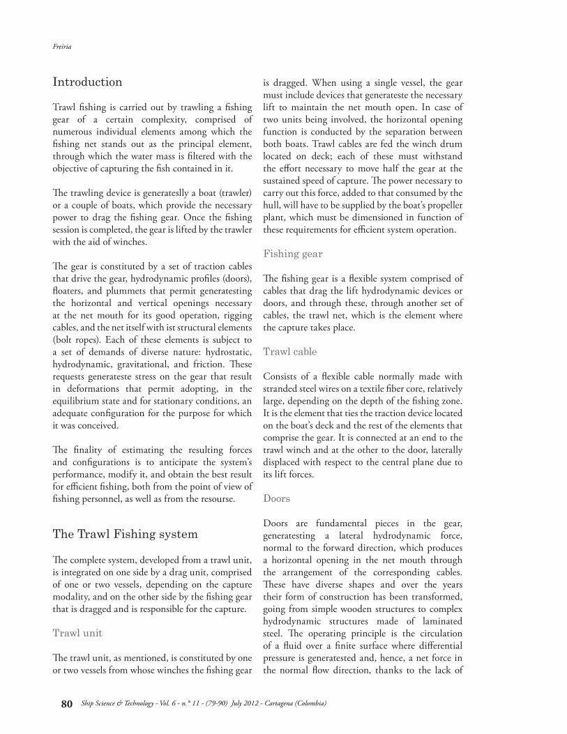
The net serves to filter water and small fish (young fish), keeping inside fish whose size corresponds to adult individuals. Meshings are designed in size to favor this distintion among sizes, an action that is denominated as “selectivity” of the art. The prior section whose shape can be modeled as a truncated cone, guides fish toward the upper part, whose essential form is a cylinder and which is denominated tunnel or copo. The upper end of the tunnel is the space where fish are finally captured. The neta consists of a structure formed by paños(layers) or sections woven of stranded wires forming regular meshings of rhomboidal shape (Fig. 1). These sections are joined among themselves, dimensioned in such a manner that once subjecting the whole to hydrodynamic and hydrostatic effort these end up adopting the configuration required; the shape it takes resembles the surface composed by a souped cone added to a cylinder, which is closed in its rear end. The front end of the cone is firmly fastened to cables that define structural aspects of the net and transmit the hydrodynamic efforts to the bridles. These are
donominated upper and lower bolt ropes. To obtain the biggest base opening of the cone or mouth of the net, a series of floaters are placed on the upper bolt rope whose mission id to raise said cable, while placing plummets on the lower bolt rope to accomplish the contrary effect; that difference of vertical forces along with the hydrodynamic forces are responsible for the vertical opening.
The analysis and representation of simple or complex physical systems requires the determination of models that can be evaluated through mathematical procedures. These models are a representation of realidad; they show via numbers the behavior of the system affected by particular environmental and physical conditions, and are developed from a set of mathematical equations.
The fishing gear constitute a complex physical system, affected by conditions related to the environment, temperature, type of bottom, and speed of the vessel. Response of the gear to these factors is unique and it is represented by a final equilibrium configuration. However, it is difficult to express this response from a simple mathematical model represented by a single algorithm where
Mathematical Model
Fig. 1. Weave of a polyethylene net
Dynamic modeling of trawl fishing gear components
Ship Science & Technology - Vol. 6 - n.° 11 - (79-90) July 2012 - Cartagena (Colombia)
82
eventually all the parameters and variables involved in the phenomenon could be integrated, and which would have a universality that would encompass the infinite modifications that could be introduced in each of the component elements.
Also, the individual components are susceptible to a mathematical modeling with greater or lesser degree of difficulty according to their structure, which permits, with appropriate idealization of the element, determining its behavior under the established operating conditions.
As of these idealizations or models, we may predict the individual configuration given by its spatial position and intervening forces, integrating these with those corresponding to each of the remaining components to determine the configuration of the whole.
This integration needs some work hypothesis, which are part of the global model: the forces and reactions that act in each individual element do not affect or are independent from the rest, maintaining continuity through the requests on the link elements among them, and symmetry exists in the arrangement of the gear with respect to the flow direction.
To calculate the hydrodynamic forces, we used Newton’s model:
Where:R is the hydrodynamic forceC is the dimensionless resistance coefficientγ is the specific weight of the fluidS is the projected surface according to a plane normal to the flow directionV is the flow rate or relative speed between the fluid and the moving element
The following describe the models adopted for each of the component elements of the bottom fishing trawl gear.
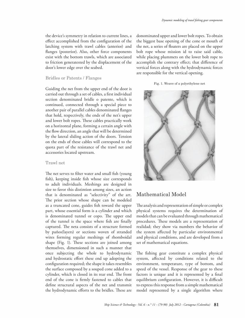
The following will present some concepts and definitions used in the development of the formulations of the drag coefficient in reference to Figs. 2 and 3:
Side of meshing: the distance between two consecutive knots over a filament of diameter d. Knot: Union of two filaments that compose the section, an equivalent diameter, dk, (sphere) is assigned.Meshing opening: denominates the angle formed by two filaments joined at a knot, seen in longitudinal sense, θ.Attack angle: is the angle formed by the meshing plane with the flow direction, α.Filtering coefficient: is the ratio between the projected area of the wire composing a meshing and the meshing area, S.
(1)
Mathematical Model for the Net
Fig. 2. Elements of an individual net Fig. 3. Idealization of elements of the net
Freiria
Ship Science & Technology - Vol. 6 - n.° 11 - (79-90) July 2012 - Cartagena (Colombia)
83
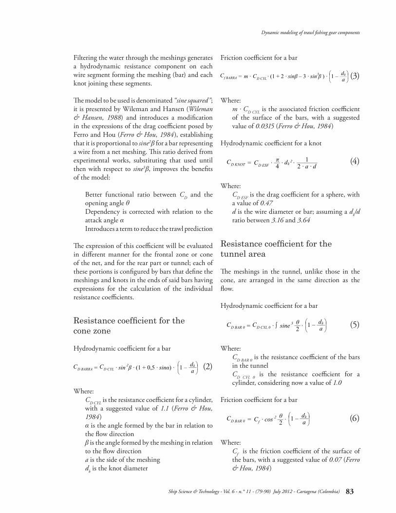
Filtering the water through the meshings generates a hydrodynamic resistance component on each wire segment forming the meshing (bar) and each knot joining these segments.
The model to be used is denominated “sine squared”; it is presented by Wileman and Hansen (Wileman & Hansen, 1988) and introduces a modification in the expressions of the drag coefficient posed by Ferro and Hou (Ferro & Hou, 1984), establishing that it is proportional to sine2β for a bar representing a wire from a net meshing. This ratio derived from experimental works, substituting that used until then with respect to sine3β, improves the benefits of the model:
Better functional ratio between CD and the opening angle θDependency is corrected with relation to the attack angle αIntroduces a term to reduce the trawl prediction
The expression of this coefficient will be evaluated in different manner for the frontal zone or cone of the net, and for the rear part or tunnel; each of these portions is configured by bars that define the meshings and knots in the ends of said bars having expressions for the calculation of the individual resistance coefficients.
Hydrodynamic coefficient for a bar
Where:CD CYL is the resistance coefficient for a cylinder, with a suggested value of 1.1 (Ferro & Hou, 1984) α is the angle formed by the bar in relation to the flow directionβ is the angle formed by the meshing in relation to the flow directiona is the side of the meshingdk is the knot diameter
Friction coefficient for a bar
Where:m . CD CYL is the associated friction coefficient of the surface of the bars, with a suggested value of 0.0315 (Ferro & Hou, 1984)
Hydrodynamic coefficient for a knot
Where:CD ESF is the drag coefficient for a sphere, with a value of 0.47d is the wire diameter or bar; assuming a dk/d ratio between 3.16 and 3.64
The meshings in the tunnel, unlike those in the cone, are arranged in the same direction as the flow.
Hydrodynamic coefficient for a bar
Where:CD BAR 0 is the resistance coefficient of the bars in the tunnelCD CYL 0 is the resistance coefficient for a cylinder, considering now a value of 1.0
Friction coefficient for a bar
Where:Cf is the friction coefficient of the surface of the bars, with a suggested value of 0.07 (Ferro & Hou, 1984)
(2)
(3)
(4)
(5)
(6)
Resistance coefficient for the cone zone
Resistance coefficient for the tunnel area
Dynamic modeling of trawl fishing gear components
Ship Science & Technology - Vol. 6 - n.° 11 - (79-90) July 2012 - Cartagena (Colombia)
84
Shadow effect
This case includes the effect produced on a wire that immediately in front, understanding that both are aligned in the flow direction, through a factor directly affecting the total resistance value:
Where:Cs is an experimental coefficient whose value can be considered equal to 1.0
Actuation areas
The previously detailed coefficients are applied to Newton’s equation to calculate hydrodynamic resistance, where the fluid’s actuation area should also be indicated.
The same coefficients are defined in function of a unitary meshing area, for which it simply remains to multiply them by the number of bars and knots according to what corresponds for each of the sections considered.
Diverse types of floaters exist; however, currently, those made of plastic materials have extended use. The shape adopted is most often spherical, with different material thicknesses according to the depths and pressures that must be endured.
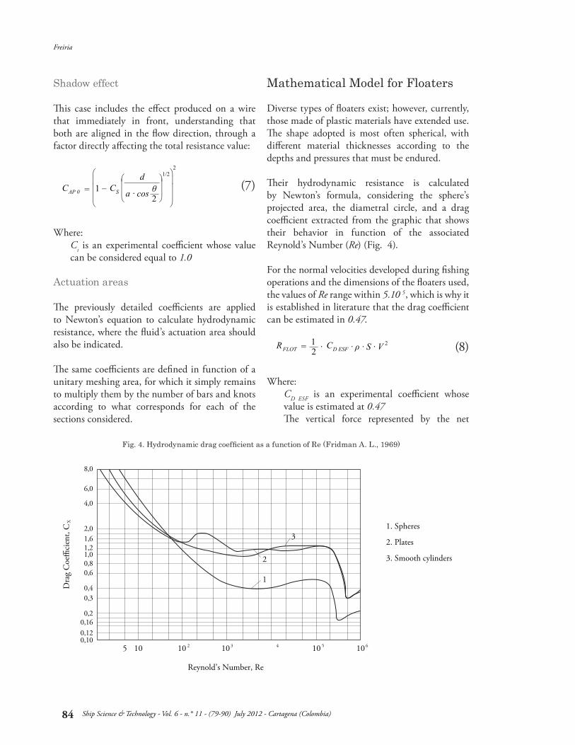
Their hydrodynamic resistance is calculated by Newton’s formula, considering the sphere’s projected area, the diametral circle, and a drag coefficient extracted from the graphic that shows their behavior in function of the associated Reynold’s Number (Re) (Fig. 4).
For the normal velocities developed during fishing operations and the dimensions of the floaters used, the values of Re range within 5.10 5, which is why it is established in literature that the drag coefficient can be estimated in 0.47.
Where:CD ESF is an experimental coefficient whose value is estimated at 0.47The vertical force represented by the net
(7)
(8)
Mathematical Model for Floaters
0,100,120,160,2
0,30,4
0,60,81,01,21,62,0
4,0
6,0
8,0
5 10 2 3 4 5 610 10
Reynold’s Number, Re
1. Spheres
2. Plates
3. Smooth cylinders
XD
rag
Coe
�ci
ent,
C
1
2
3
10 10
Fig. 4. Hydrodynamic drag coefficient as a function of Re (Fridman A. L., 1969)
Freiria
Ship Science & Technology - Vol. 6 - n.° 11 - (79-90) July 2012 - Cartagena (Colombia)
85
flotation should also be considered, calculated as the difference between absolute flotation and the unit weight.
Dragging gear elements over the seabed, as with plummets, generates efforts derived from the friction appearing on the interfase. This force depends on the weight of the moving element, on the surface of actuation or friction, on the type of surface and on the type of relative movement (glide, rolling).
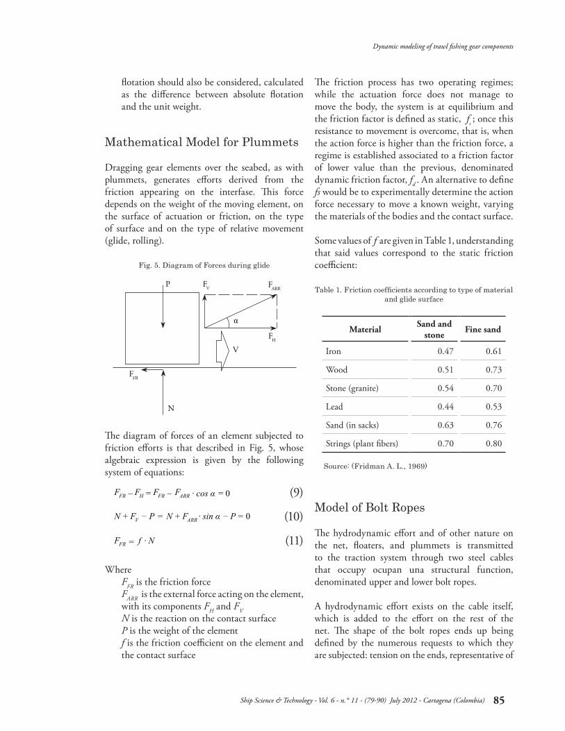
The diagram of forces of an element subjected to friction efforts is that described in Fig. 5, whose algebraic expression is given by the following system of equations:
WhereFFR is the friction forceFARR is the external force acting on the element, with its components FH and FVN is the reaction on the contact surfaceP is the weight of the elementf is the friction coefficient on the element and the contact surface
The friction process has two operating regimes; while the actuation force does not manage to move the body, the system is at equilibrium and the friction factor is defined as static, fs ; once this resistance to movement is overcome, that is, when the action force is higher than the friction force, a regime is established associated to a friction factor of lower value than the previous, denominated dynamic friction factor, fd . An alternative to define fs would be to experimentally determine the action force necessary to move a known weight, varying the materials of the bodies and the contact surface.
Some values of f are given in Table 1, understanding that said values correspond to the static friction coefficient:
The hydrodynamic effort and of other nature on the net, floaters, and plummets is transmitted to the traction system through two steel cables that occupy ocupan una structural function, denominated upper and lower bolt ropes.
A hydrodynamic effort exists on the cable itself, which is added to the effort on the rest of the net. The shape of the bolt ropes ends up being defined by the numerous requests to which they are subjected: tension on the ends, representative of
(9)
(10)
(11)
Mathematical Model for Plummets
Model of Bolt Ropes
V
FARR
FFR
FP
N
α
V
FH
Fig. 5. Diagram of Forces during glide
Material Sand and stone Fine sand
Iron 0.47 0.61
Wood 0.51 0.73
Stone (granite) 0.54 0.70
Lead 0.44 0.53
Sand (in sacks) 0.63 0.76
Strings (plant fibers) 0.70 0.80
Table 1. Friction coefficients according to type of material and glide surface
Source: (Fridman A. L., 1969)
Dynamic modeling of trawl fishing gear components
Ship Science & Technology - Vol. 6 - n.° 11 - (79-90) July 2012 - Cartagena (Colombia)
86
the vessel’s drag; tension from the net distributed throughout its whole length; tension from floaters in one case and from plummets in another.
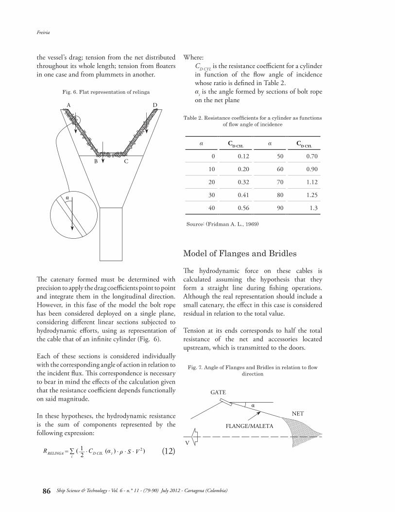
The catenary formed must be determined with precision to apply the drag coefficients point to point and integrate them in the longitudinal direction. However, in this fase of the model the bolt rope has been considered deployed on a single plane, considering different linear sections subjected to hydrodynamic efforts, using as representation of the cable that of an infinite cylinder (Fig. 6). Each of these sections is considered individually with the corresponding angle of action in relation to the incident flux. This correspondence is necessary to bear in mind the effects of the calculation given that the resistance coefficient depends functionally on said magnitude.
In these hypotheses, the hydrodynamic resistance is the sum of components represented by the following expression:
Where:CD CYL is the resistance coefficient for a cylinder in function of the flow angle of incidence whose ratio is defined in Table 2.αi is the angle formed by sections of bolt rope on the net plane
The hydrodynamic force on these cables is calculated assuming the hypothesis that they form a straight line during fishing operations. Although the real representation should include a small catenary, the effect in this case is considered residual in relation to the total value.
Tension at its ends corresponds to half the total resistance of the net and accessories located upstream, which is transmitted to the doors.
Fig. 6. Flat representation of relinga
Fig. 7. Angle of Flanges and Bridles in relation to flow direction
B
A D
C
α
(12)
α CD CYL α CD CYL
0 0.12 50 0.70
10 0.20 60 0.90
20 0.32 70 1.12
30 0.41 80 1.25
40 0.56 90 1.3
Table 2. Resistance coefficients for a cylinder as functions of flow angle of incidence
Source: (Fridman A. L., 1969)
Model of Flanges and Bridles
V
GATE
FLANGE/MALETA
NETα
Freiria
Ship Science & Technology - Vol. 6 - n.° 11 - (79-90) July 2012 - Cartagena (Colombia)
87
The calculation in this case can be reduced to that of a cylinder of known dimensions, which forms a given angle α with the incident flux. The incidence angle is deducted from the initial conditions imposed by the model and then from successive iterations until reaching the regime condition.
Where:CD CYL is the resistance coefficient for a cylinder in function of the incidence angleα is the angle formed by the flange or bridle with the incident flux
The door is an element inserted in the cable line linking the vessel and the net, and whose function is to generate a lateral force that permits expanding the distance between both trawl cables and permit the transversal opening of the mouth of the art. It consists of a vertical structure that generates a lift force (normal to the flow direction), which is responsible for the mentioned lateral expasion, besides a resistance to drag, like the rest of the gear elements.
The drag and lift forces have a direct link with the shapes of these devices. The most elemental and primitive consist of flat plates, with a very low lift/drag ratio, rates that have been improved through the current hydrodynamic designs. The values of these forces are calculated by using the coefficients provided by the manufacturers.
Where:CD DOOR and CL DOOR with the drag and lift coefficients (according to manufacturer)
Doors, as well as plummets fastened to the lower bolt rope, work by dragging through the seabed for which a friction component exists that must be added to the resistances calculated. Said component, relatively smaller in comparative terms with the door resistance values, is calculated by using friction data established in Table 1, as seen previously.
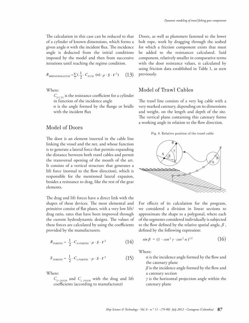
The trawl line consists of a very log cable with a very marked catenary, depending on its dimensions and weight, on the length and depth of the site. The vertical plane containing this catenary forms a working angle in relation to the flow direction.
For effects of its calculation for the program, we considered a division in linear sections to approximate the shape to a polygonal, where each of the segments considered individually is subjected to the flow defined by the relative spatial angle, β , defined by the following expression:
Where:α is the incidence angle formed by the flow and the catenary planeβ is the incidence angle formed by the flow and a catenary sectionγ is the horizontal projection angle within the catenary plane
Fig. 8. Relative position of the trawl cable
(13)
(14)
(15)
(16)
Model of Doors
Model of Trawl Cables
αβ
γ
A
AB
B
Dynamic modeling of trawl fishing gear components
Ship Science & Technology - Vol. 6 - n.° 11 - (79-90) July 2012 - Cartagena (Colombia)
88
Onced defined angle β, the drag coefficient is calculated for that bar by using the ratio of drag coefficients for a bar in function of the angle (Table 2).
The main dificulty in implementing a model is selecting a set of initial conditions with which we manage to establish a first spatial configuration of the gear, and on which mathematical models can be applied of the individual elements to then integrate them in the whole; as of this first configuration and through successive approximations, a geometric and dynamic conditon of equilibrium can be established.
Works carried out by Nomura and Yamazaki (Nomura & Yamazaki, 1975) permit conducting this approximation from the experimental formulation for trawl net resistance whose expression is the following:
Where:RNET , Net’s resistance to drag (N)Lm , extended perimeter of the mouth of the net (m)Ln , length of the extended net (m)Dt , mean diameter of the wire (mm)ms , length of the mean meshing (mm)V , velocity (m/s)g , gravity acceleration (m/s2)
From this initial value corresponding to the net’s resistance with its gear, without including the resistance of the doors, the first spatial configuration of the system is determined from the geometric-dynamic ratios presented by Fridman (Fridman, 1986 ), defined by the vertical and horizontal openings of the mouth of the net, and the openings of doors.
Upon defining the gear’s first spatial configuration, we calculated for each of the individual component elements the hydrodynamic forces and forces of other nature that act on these, by applying the expressions developed previously and which constitute the core of the mathematical model. Now, we include the forces developed by the trawl doors, which are not considered in the calculation according to Nomura’s formula.
With the different components of forces resulting from the application of the different algorithms calculated, the gear configuration is again defined, which will present variants with respect to the initial configuration, as the value of the forces takes a different value than the initial value.
We can, therefore, visualize in these first steps the philosophy of the model, which represents in discrete manner a process that in nature occurs continuouslly, the interaction among the set of forces applied to a flexible complex system, and its spatial configuration as of the internal tensions.
Initial conditions
Modeling of Case Studies
(17)
06,0
7,0
8,0
9,0
5 10 15 20 25 30
R(T
on)
N
Número de Interacciones
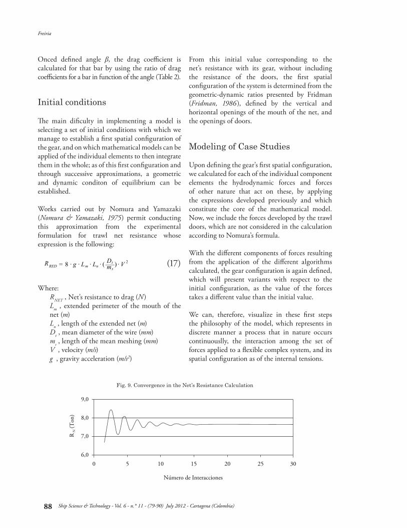
Fig. 9. Convergence in the Net’s Resistance Calculation
Freiria
Ship Science & Technology - Vol. 6 - n.° 11 - (79-90) July 2012 - Cartagena (Colombia)
89
The calculation process in alternative and interactive manner between the forces and geometric configuration reflects the physical reality of this type of system. A mechanism is included to end the calculation stage having reached conditions of dynamic equilibrium, consisting in establishing a difference among the values obtained in two consecutive steps whose difference is transformed into a marginal value pre-established as a percentage of the calculated total.
Convergence is a fundamental condition for the viability of the model; in all fields defined it is rapidly accomplished. Fig. 9 shows the behavior of the Net resistance, RN, variable.
This enhances the application in two senses: on the one hand the rapidity of the response to variations introduced, and on the other the robustness of the code.
After ending the stage of constructing the logical structure and introducing the algorithms that represent each of the elements of the model, this was tested to visualize its convergence, an aspect mentioned before, and verify alignment of the results obtained with comparative data that will have a high level of operator confidence.
The data available to conduct the validation were provided by competent personnel directly involved in the determination of the measurements through ultrasound probes, which is why they are considered valid data for the effects of the current review.
The nets used in the comparison excercise have the general characteristics indicated ahead, establishing in Table 3 to Table 5 the corresponding comparative values.
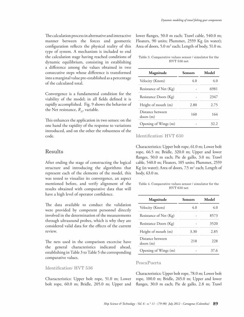
Identification: HVT 536
Characteristics: Upper bolt rope, 51.0 m; Lower bolt rope, 60.0 m; Bridle, 205.0 m; Upper and
lower flanges, 50.0 m each; Trawl cable, 540.0 m; Floaters, 90 units; Plummet, 2559 Kg (in water); Area of doors, 5.0 m2 each; Length of body, 51.0 m.
Identification: HVT 630
Characteristics: Upper bolt rope, 61.0 m; Lower bolt rope, 66.5 m; Bridle, 320.0 m; Upper and lower flanges, 50.0 m each; Pie de gallo, 3.0 m; Trawl cable, 540.0 m; Floaters, 105 units; Plummet, 2559 Kg (in water); Area of doors, 7.5 m2 each; Length of body, 63.0 m.
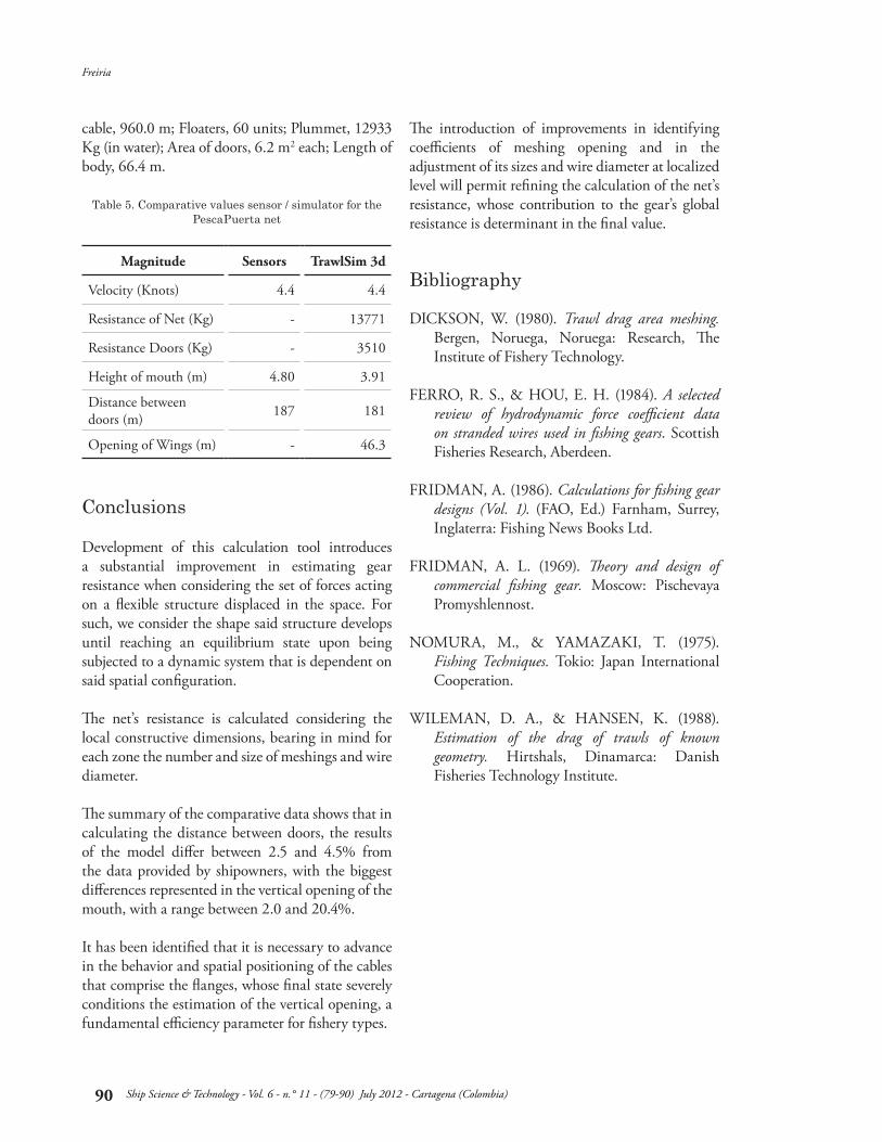
PescaPuerta
Characteristics: Upper bolt rope, 78.0 m; Lower bolt rope, 100.0 m; Bridle, 265.0 m; Upper and lower flanges, 30.0 m each; Pie de gallo, 2.8 m; Trawl
Results
Magnitude Sensors Model
Velocity (Knots) 4.0 4.0
Resistance of Net (Kg) - 6981
Resistance Doors (Kg) - 2347
Height of mouth (m) 2.80 2.75
Distance between doors (m) 160 164
Opening of Wings (m) - 32.2
Magnitude Sensors Model
Velocity (Knots) 4.0 4.0
Resistance of Net (Kg) - 8573
Resistance Doors (Kg) - 3520
Height of mouth (m) 3.30 2.85
Distance between doors (m) 218 228
Opening of Wings (m) - 37.6
Table 3. Comparative values sensor / simulator for the HVT 536 net
Table 4. Comparative values sensor / simulator for the HVT 630 net
Dynamic modeling of trawl fishing gear components
Ship Science & Technology - Vol. 6 - n.° 11 - (79-90) July 2012 - Cartagena (Colombia)
90
cable, 960.0 m; Floaters, 60 units; Plummet, 12933 Kg (in water); Area of doors, 6.2 m2 each; Length of body, 66.4 m.
Development of this calculation tool introduces a substantial improvement in estimating gear resistance when considering the set of forces acting on a flexible structure displaced in the space. For such, we consider the shape said structure develops until reaching an equilibrium state upon being subjected to a dynamic system that is dependent on said spatial configuration.
The net’s resistance is calculated considering the local constructive dimensions, bearing in mind for each zone the number and size of meshings and wire diameter.
The summary of the comparative data shows that in calculating the distance between doors, the results of the model differ between 2.5 and 4.5% from the data provided by shipowners, with the biggest differences represented in the vertical opening of the mouth, with a range between 2.0 and 20.4%.
It has been identified that it is necessary to advance in the behavior and spatial positioning of the cables that comprise the flanges, whose final state severely conditions the estimation of the vertical opening, a fundamental efficiency parameter for fishery types.
The introduction of improvements in identifying coefficients of meshing opening and in the adjustment of its sizes and wire diameter at localized level will permit refining the calculation of the net’s resistance, whose contribution to the gear’s global resistance is determinant in the final value.
DICKSON, W. (1980). Trawl drag area meshing. Bergen, Noruega, Noruega: Research, The Institute of Fishery Technology.
FERRO, R. S., & HOU, E. H. (1984). A selected review of hydrodynamic force coefficient data on stranded wires used in fishing gears. Scottish Fisheries Research, Aberdeen.
FRIDMAN, A. (1986). Calculations for fishing gear designs (Vol. 1). (FAO, Ed.) Farnham, Surrey, Inglaterra: Fishing News Books Ltd.
FRIDMAN, A. L. (1969). Theory and design of commercial fishing gear. Moscow: Pischevaya Promyshlennost.
NOMURA, M., & YAMAZAKI, T. (1975). Fishing Techniques. Tokio: Japan International Cooperation.
WILEMAN, D. A., & HANSEN, K. (1988). Estimation of the drag of trawls of known geometry. Hirtshals, Dinamarca: Danish Fisheries Technology Institute.
Magnitude Sensors TrawlSim 3d
Velocity (Knots) 4.4 4.4
Resistance of Net (Kg) - 13771
Resistance Doors (Kg) - 3510
Height of mouth (m) 4.80 3.91
Distance between doors (m) 187 181
Opening of Wings (m) - 46.3
Table 5. Comparative values sensor / simulator for the PescaPuerta net
Conclusions
Bibliography
Freiria
Ship Science & Technology - Vol. 6 - n.° 11 - (79-90) July 2012 - Cartagena (Colombia)