Dynamic Modeling and Construction of a New Two-Wheeled Mobile Manipulator: Self-balancing and Climbi
13
International Journal of Robotics, Vol. 4, No. 3, (2015) S. Ebrahimi, A. Mardani, 22-34 * Corresponding author address: Yazd University, Safayieh, Yazd, Iran. Tel.: +983531232621; fax: +9835382112781, E-mail address: [email protected]. 22 Dynamic Modeling and Construction of a New Two-Wheeled Mobile Manipulator: Self- balancing and Climbing S. Ebrahimi a,* , A. Mardani b a Associate Professor, Department of Mechanical Engineering, Yazd University, Yazd, Iran. b PhD Student, Department of Mechanical Engineering, Yazd University, Yazd, Iran. A R T I C L E I N F O A B S T R A C T Article history: Received: July 20, 2015. Received in revised form: September 29, 2015 Accepted: October 5, 2015. Designing the self-balancing two-wheeled mobile robots and reducing undesired vibrations are of great importance. For this purpose, the majority of researches are focused on application of relatively complex control approaches without improving the robot structure. Therefore, in this paper we introduce a new two- wheeled mobile robot which, despite its relative simple structure, fulfills the required level of self-balancing without applying any certain complex controller. To reach this goal, the robot structure is designed in a way that its center of gravity is located below the wheels' axle level. The attention is more paid to obtaining a self-balancing model in which the robot’s arms and other equipment follow relatively low oscillations when the robot is subjected to a sudden change. After assembling the robot using the Sim-Mechanics toolbox of Matlab, several simulations are arranged to investigate the robot ability in fulfilling the required tasks. Further verifications are carried out by performing various experiments on the real model. Based on the obtained results, an acceptable level of balancing, oscillation reduction, and power supply is observed. To promote the self- balancing two-wheeled mobile manipulator, its platform is modified to climb high obstacles. In order to obtain this aim, some transformations are done in mechanical aspects like wheels, arms and main body without any increase in DOFs. The robot is supposed to follow proposed motion calculated according to stability criteria. The kinematic equations are utilized to find a possible motion. In a dynamic simulation, the robot ability in passing over an obstacle is verified. Keywords: Self-stability Two-wheeled robots Stair climbing Mobile manipulator 1. Introduction Promotion of the robotic world is the best evidence of necessity of transforming human based missions to automatic processes based on ability of robots. Most of the peril applications are done by means of automatic devices. Mobile manipulators are used for exploring missions or industrial applications. In all applications, mathematical modeling, path planning, fluctuation elimination and using of appropriate mechanisms are necessary. Widespread researches are handled in mobile manipulator field previously [1, 2]. Stability and fluctuation elimination is the most important matters which must be investigated. In some researches, the
-
Upload
international-journal-of-robotics-theory-and-applications -
Category
Documents
-
view
219 -
download
1
description
Designing the self-balancing two-wheeled mobile robots and reducing undesired vibrations are of great importance. For this purpose, the majority of researches are focused on application of relatively complex control approaches without improving the robot structure. Therefore, in this paper we introduce a new two-wheeled mobile robot which, despite its relative simple structure, fulfills the required level of self-balancing without applying any certain complex controller. To reach this goal, the robot structure is designed in a way that its center of gravity is located below the wheels' axle level. The attention is more paid to obtaining a self-balancing model in which the robot’s arms and other equipment follow relatively low oscillations when the robot is subjected to a sudden change. After assembling the robot using the Sim-Mechanics toolbox of Matlab, several simulations are arranged to investigate the robot ability in fulfilling the required tasks. Further verifications are carried
Transcript of Dynamic Modeling and Construction of a New Two-Wheeled Mobile Manipulator: Self-balancing and Climbi

International Journal of Robotics, Vol. 4, No. 3, (2015) S. Ebrahimi, A. Mardani, 22-34
* Corresponding author address: Yazd University, Safayieh, Yazd, Iran.
Tel.: +983531232621; fax: +9835382112781, E-mail address: [email protected].
22
Dynamic Modeling and Construction of a New
Two-Wheeled Mobile Manipulator: Self-
balancing and Climbing
S. Ebrahimia,*, A. Mardanib a Associate Professor, Department of Mechanical Engineering, Yazd University, Yazd, Iran. b PhD Student, Department of Mechanical Engineering, Yazd University, Yazd, Iran.
A R T I C L E I N F O A B S T R A C T
Article history:
Received: July 20, 2015. Received in revised form:
September 29, 2015
Accepted: October 5, 2015.
Designing the self-balancing two-wheeled mobile robots and reducing undesired
vibrations are of great importance. For this purpose, the majority of researches are
focused on application of relatively complex control approaches without
improving the robot structure. Therefore, in this paper we introduce a new two-
wheeled mobile robot which, despite its relative simple structure, fulfills the
required level of self-balancing without applying any certain complex controller.
To reach this goal, the robot structure is designed in a way that its center of
gravity is located below the wheels' axle level. The attention is more paid to
obtaining a self-balancing model in which the robot’s arms and other equipment
follow relatively low oscillations when the robot is subjected to a sudden change.
After assembling the robot using the Sim-Mechanics toolbox of Matlab, several
simulations are arranged to investigate the robot ability in fulfilling the required
tasks. Further verifications are carried out by performing various experiments on
the real model. Based on the obtained results, an acceptable level of balancing,
oscillation reduction, and power supply is observed. To promote the self-
balancing two-wheeled mobile manipulator, its platform is modified to climb high
obstacles. In order to obtain this aim, some transformations are done in
mechanical aspects like wheels, arms and main body without any increase in
DOFs. The robot is supposed to follow proposed motion calculated according to
stability criteria. The kinematic equations are utilized to find a possible motion. In
a dynamic simulation, the robot ability in passing over an obstacle is verified.
Keywords:
Self-stability
Two-wheeled robots
Stair climbing Mobile manipulator
1. Introduction
Promotion of the robotic world is the best evidence of
necessity of transforming human based missions to
automatic processes based on ability of robots. Most of
the peril applications are done by means of automatic
devices. Mobile manipulators are used for exploring
missions or industrial applications. In all applications,
mathematical modeling, path planning, fluctuation
elimination and using of appropriate mechanisms are
necessary. Widespread researches are handled in mobile
manipulator field previously [1, 2]. Stability and
fluctuation elimination is the most important matters
which must be investigated. In some researches, the
International Journal of Robotics, Vol. 4, No.3, (2015) S. Ebrahimi, A. Mardani, xx-xx
23
stability has been satisfied by mean of additional
passive rollers [3, 4]. The stability investigations used in
mobile manipulator field like moment height stability
measure (MHS) are done [5-7]. This criterion is
established on applied torques on mobile platform, the
height of CG and inertia of mobile platform. Stability
investigation of the dual arm suspended mobile robot
has been proposed by means of MHS criterion [6]. In
related researches, dynamic stability of a hybrid mobile
manipulator is illustrated in [7] by means of MHS to
enhance stability of platform. In other researches, force-
angle measure is utilized to investigate mobile
manipulator stability [8].
In these researches, application of arm and base
actuators is the way to prevent over turning. Promotion
of the mobile manipulators stability is done not only by
means of mechanism innovation but also implementing
control algorithms such as neural-fuzzy controllers [9].
In some platforms, the center of mass is moved by
controller to satisfy stability criteria [10]. In recent few
years, development of two-wheeled mobile
manipulators has found great attention. Ha and Yuta
focused on the control of a two-wheeled robot with
inverse pendulum structure based on the robot velocity
[11]. Grasser has provided stability for a two-wheeled
mobile manipulator by means of dual state space
controller [12]. In related research, a 3-DOF model of
the two-wheeled robot is proposed [13]. In this paper,
non-holonomic locomotion on ramps is investigated
dynamically by means of dynamic approaches. In
another research, the stabilization is assumed to be done
by the LQR controller [14]. Some two-wheeled robot
dynamic investigations are based on the Newton-Euler
approach and PD controller [15]. In [16], after deriving
and linearization of the dynamic equations of motion,
stability control of the robot is performed using the pole
placement method in real time toolbox of Matlab. A
two-wheeled mobile robot with flexible links is
modeled based on the combined approach of
D’Alembert-Lagrange [17, 18]. Independent control of
each wheel in a two-wheeled robot is proposed in [19].
In other effort, stability is investigated when the load
installed on arm moves [20]. For this purpose, PD
controller is utilized beside fuzzy logic. The results of
simulation proof the stability under external load as
disturbance force. In other control based effort [21],
robust controller is utilized after extraction of dynamic
equations. Motion equations are linearized about
stability point of the robot arm. Then, they are rewritten
into state space equations. This controller is investigated
in the case of undetermined coefficient of friction. The
stability control of a two-wheeled robot in tracking a
prescribed path is investigated in [22]. In this case, the
process of arm controlling is done by means of PD
controller and optical sensors. In other paper, mobile
manipulator is controlled by means of fuzzy controller
based on the velocity and position [23].As a related
effort, stability control of a two- wheeled mobile
manipulator is analyzed on the ramps [24]. To proof the
aim of this paper, the Lagrange approach is utilized.
Then, Lyapunov method is used to determine stability
margins. Position and velocity control process based on
the optimal controller is done to satisfy stability
margins. As the other effort related to the locomotion on
ramp, a dynamical simulation is done in [25, 26].
Extracted equations are used to simulate locomotion on
even surfaces or ramps. According to optimal control
based on the optimal gains, stability of mobile
manipulator is investigated. Juang and Lum [27]
considered the dynamic simulation of two-wheeled
robots by means of using various PID based controllers.
On an uneven surface, climbing can improve ability of
locomotion. Mobile robots that can climb obstacles, or
stairs have been investigated in order to generalize their
missions. As a solution, the wheel of mobile
manipulator can be transformed to be in [28], the body
is knitted to two parts to elevate easier [29]. In other
more complex solution, wheels are armed by active
linkages [30]. The hybrid locomotion done by complex
leg (linkage and wheel) can improve ability of climbing
besides legged locomotion. Some of climbers are armed
by passive linkages [31, 32]. In other efforts, 1-DOF
link is deformed to the half circle shape [33, 34]. Rhex
is a novel platform improved to running and climbing
[35]. Some other mobile platforms are specially
designed for climbing like Msrox [36, 37]. Msrox is a
four-wheeled rover armed by hybrid wheels to climb
stairs. The hybrid wheel composition is obtained from
installing three wheels on a triangular part. Triangular
part is located on each wheel connection point on the
main body. In other effort, a four-wheeled robot armed
by parallel mechanism is proposed to climb stair [38]. In
this research, using of linkage is considered to obtain
climber mechanism. As a powerful climber mechanism,
a rail mobile manipulator is proposed in a hybrid
structure. This mechanism is designed based on
compounded duty of mobile part and manipulator part
in climbing and locomotion missions [49], [40]. The
research reported in [39], [40] is the first inspiration for
new idea of current development to improve new
mechanism proposed at the previous part of
introduction. Hybrid locomotion using arm beside
mobile parts is a good solution to climbing.
In this paper, we first introduce a new two-wheeled
mobile robot which, despite its relative simple structure,
fulfills the required level of self-balancing without
applying any certain complex controller. To reach this
goal, the robot structure is designed in way that its
center of gravity to be located below the wheels' axle
level. In the first part of this article, a newly developed
self-balancing two-wheeled mobile manipulator was
presented. For this purpose, the robot structure was
designed in way that its center of gravity is located
below the wheels' axle level. In the final model of the

International Journal of Robotics, Vol. 4, No.3, (2015) S. Ebrahimi, A. Mardani, xx-xx
24
robot, the attention was more paid to obtain a self-
balancing model in which the robot’s arms and other
equipment follow relatively low oscillations when the
robot is subjected to a sudden change.
In the next part of the paper, the self-balancing two-
wheeled manipulator will be promoted to a climber
mechanism by some changes in mechanical parts like
wheels, manipulator and main body without any
increasing in DOFs,. Besides mechanical
transformation, stability criteria must be involved in
motion planning. A proposed motion will be planned to
climbing high obstacles in stability margins.
To obtain a proper platform, at the first stage, a primary
virtual model of new two wheeled mobile manipulator
controlled by PID controller was designed in Matlab
Simulink (Sim-Mechanic) according to the primary
experimental model. The aim of virtual model was
detection of disadvantages of new platform specially
fluctuation of locomotion. After assembling the robot
using the Sim-Mechanics toolbox of Matlab, several
simulations were arranged to investigate the robot
ability in fulfilling the required tasks. Further
verifications were carried out by performing various
experiments on the real model. At the next stage, two
experimental tests were considered to proof the abilities
of the new platform in real locomotion. In experimental
test the maximum limits of ability in obstacle crossing
and ramp climbing was investigated besides fluctuation
monitoring. Based on the obtained results, an acceptable
level of balancing, oscillation reduction, and power
supply was observed.
However, this new platform cannot continue working
against high obstacles. There are many considerations
must be applied on the new platform to be a successful
as a mobile manipulator in performing certain missions.
To eliminate the leak of ability on of climbing some
virtual tests will be done to show the power of
promotion of new platform to a climber robot.
2. New platform
The new platform concept is illustrated in Fig. 1.
Fig. 1. Concept of platform.
As it is illustrated, mobile manipulator includes three
main parts (main body, manipulator and wheels). The
main body located under wheel axis allows robot to be
stable permanently due to the center of gravity (CG)
place which is shown in Fig. 1. A connection part
including five revolute joints illustrated in Fig. 2 is
designed to connect the parts of robot. As it is shown,
the universal connection is a circular part that connects
wheels to the manipulator arm and main body. On the
other hand, connection part allows the main body and
manipulator to rotate about X axis besides rotating
about Y axis. This provided ability keeps robot arm
coordinates vertical in ramps. A primary experimental
model is fabricated to show real ability of the new
mobile manipulator.
Fig. 2. Central universal joint: (1) ball bearing of the front of
the robot, (2) central link to connect main body, (3)
connection of main body, (4) ball bearing of the rear of robot,
(5) left wheel connection, (6) ball bearing of the left wheel, (7)
right wheel connection, (8) ball bearing of the right wheel, (9)
connection ring of ball bearing.
As it is illustrated in Fig. 3, the first link of the
manipulator is hidden under steel cover. Properties of
the new model motors are provided in Table 1. There is
no necessity to express properties of the control devices
used in experimental model. Mechanical properties are
given in Tables 4 and 5 of Appendix.
Main body of the robot
Manipulator
Right wheel
Left wheel
The center of mass
1
2
3
5
4
6
7
8
9
X
Y

International Journal of Robotics, Vol. 4, No.3, (2015) S. Ebrahimi, A. Mardani, xx-xx
25
Fig. 3. Primary real model.
Table 1. The characteristic of motors
Wheel motor Arm motor Properties
4watt
9N.m
60rpm
6V
0.4H
0.8Ω
18
4watt
3N.m
180rpm
6V
0.4 H
0.8Ω
6
Maximum power
Stall torques
Load less velocity
Voltages
Inductance coefficient
Internal resistance
Ratio of gear box
3. Kinematics, dynamics and control
The kinematic and dynamic parameters of the 2D model
are provided in Fig. 4. At the first stage, the components
of CG acceleration are extracted in Eq. 1. The main
assumption is non-sliding condition.
(1)
21 1 1 1 1
1 21 1 1 1 1
cos( ) sin( )
0 sin( ) cos( )
x
y
a rc
a
where 1c is the center of gravity position of the main
body. Determination of the first link acceleration of
manipulator is expressed in Eq. 2. In the same way, Eq.
3 expresses the acceleration of the second link where
1 2 and
1 2 3 .
(2)
22
2 22
sin( ) cos( )
0 cos( ) sin( )
x
y
a rc
a
(3)
According to Fig. 5, moment balance of the second link
is driven by the Newton-Euler approach. Parameter 𝐼3 is
the mass moment of inertia of the link about3CG . The
second equation is driven by applying the recursive
method in Eq. 4 according to Fig. 6.
(4) 1 3 3 3
3 3 3 3 3
3 3 3
cos( )
sin( )
cos( )
O
x
y
M m gc
I m a c
m a c
(5)
2 3 2 2
3 2 3
2 2 2 2 2 2 2 2
3 3 3 3 2 3
3 3 2 3
cos( )
cos( ) cos( )
sin( ) cos( )
sin( ) sin( )
cos( ) cos( )
O
x y
x
y
M m gc
m g l c
I m a c m a c
I m a l c
m a l c
Fig. 4. Kinematic and dynamic parameters.
Fig. 5. The first link of manipulator.
23
2 23
2
3 2
sin( ) cos( )
0 cos( ) in( )
sin( ) ( ) cos( )
cos( ) ( ) sin( )
x
y
a rl
a s
c

International Journal of Robotics, Vol. 4, No.3, (2015) S. Ebrahimi, A. Mardani, xx-xx
26
Fig. 6. Both of the first and second links.
Two other dynamic equations are driven by means of
the Newton second low.
(6)
2 2 2 3 3
2 2 3 2 2 3 3
x x x
y y y
f m a m a
f m g m g m a m a
The next step is extraction of the wheel equation. Eq. 7
shows the wheel equation. Ic is inertia of the wheel
about point C in Fig. 4. The last step is derivation of the
equations of the main body as given in Eq. 8. Figure 7
illustrates the wheel and main body properties.
(7) 0
x
y
C x C
f f ma mr
f mg N
M f r I
(8)
2 1 1
2 1 1 1
2 2 1 1
2 1 1 1 1
( ) sin( )
( ) cos( )
x x x
y y y
G y y
x x
f f m a
f f m g m a
M f f c
f f c I
Fig. 7. Wheel and main body.
The system equations including Eqs. 4-8 consist of 10
equations which must be solved simultaneously with
Eqs. 1-3. Undefined parameters are 2 ،
3 ،xf ،
yf ،2xf ،
2 yf ، f ، ،1 and N.
Control low used in this paper is expressed in Eq. 9.
According to Eq. 9, y is feedback parameter, r is control
signal input, G is control signal output, N is noise
elimination coefficient, and b and c are weight gains set
on one. The equation is driven from [41]. The control
low will be utilized for the manipulator and wheel. Fig.
8 shows the algorithm of control including Eq. 9.
(9) ( ) ( ) ( ) ( )
1
I NG s P br y r y D cr y
Ns
s
4. Simulation and experimental efforts
This section is based on three main efforts. The first
case is simulation of the robot on flat surface using
Matlab Simulink (Sim-Mechanic) and its control by
means of Eq. 9. The control panel of Simulink is
provided in Fig. 25 of Appendix. In the second test, it is
simulated in the dynamic simulation part of SolidWorks
to show the ability of robot in ramp climbing. The last
effort is done experimentally. In these stages, two parts
are provided. The first is obstacle crossing and the
second is ramp climbing. At the first stage, robot starts
to move by initial condition (v = 0, a = constant and x =
0) for 8 seconds, see Fig. 9. The aim is monitoring the
fluctuation of main body with respect to the fixed
coordinate. Manipulator motors are supposed to be
fixed. The results of angular displacement are illustrated
in Fig. 10-a, for various damping coefficient of the
wheel joint (B = 0.6, 1.2, 2). By choosing B = 2
according to Fig. 10-a, Fig. 10-b illustrates fluctuation
of the main body with respect to the fixed coordinate
system for various linear accelerations of the wheel (a =
1, 3, 5 m/s2).
Fig. 8. Control algorithm.

International Journal of Robotics, Vol. 4, No.3, (2015) S. Ebrahimi, A. Mardani, xx-xx
27
Fig. 9. Constant acceleration movement.
(a)
(b)
Fig. 10. Angular displacement of the main body.
Another simulation is performed in SolidWorks. In this
simulation, ramp climbing will be investigated in
various ramp angles ( 0, 15, 25, 35 deg)s . Fig. 11
shows typical ramp climbing. The friction coefficient of
surface is 0.4. In gentle ramps, robot climbs up
properly. By increasing the value of 𝜃𝑠, climbing
becomes slower and in 35 degree, robot goes down in
spite of climbing mission. The torque of motor is
limited between 0 to 9 N.m. The results of robot
displacement and also the motor torques are provided in
Fig. 12.
Fig. 11. Ramp climbing.
(a)
(b)
Fig. 12. Ramp climbing result
The experimental test is arranged for ramp climbing to
validate the simulation results. In this test, robot is
supposed to climb ramps in various slops and various
friction coefficients. Table 2 expresses the result of
experimental model. S means successful locomotion and
N is failed test.
In other experimental test, the robot is supposed to cross
obstacles (Fig. 13). The test is managed in various
heights of obstacle (0.05, 0.1, 0.12, 0.16 m).
Furthermore, in another effort, new flexible belt with
pretension is used in manipulator links to reduce the
effect of gravity and fluctuations on the arm motors as
illustrated in Fig. 14.
Table 2. Slop climbing result
Friction
coefficient
Slop=25 Slop=20 Slop=15 Slop=10
0.1 N N S S
0.2 N S S S
0.4 S S S S
Fig. 13. Obstacle crossing.
v = 0, a = 0.05, 1 m/s2, x = 0
Height of obstacle
Low initial velocity

International Journal of Robotics, Vol. 4, No.3, (2015) S. Ebrahimi, A. Mardani, xx-xx
28
Fig. 14. Flexible belt with pretension.
According to the results of Table 3, robot cannot pass
the 0.16m obstacle without flexible belt, which in the
case of using the flexible belt, it can pass the obstacle.
Table 3. Obstacle climbing
Obstacle height 0.05 0.1 0.12 0.16
Crossing without
flexible belt
S S S N
Crossing with flexible
belt
S S S S
5. Promotion to the climber model
The newly developed platform can further be modified
to be a climber mobile manipulator. The main body
shape and manipulator are modified as shown in Fig.
15. The wheels are reconstructed by adding jagged
surface. Fig.15 (a-1) is the primary new platform and (a-
2) is the modified platform armed by jagged wheels.
Fig. 15 (b-1) shows the primary form of the main body
where (b-2) shows modified shape of the main body.
Figs. 15 (c-1) and (c-2) present the primary and the
modified manipulators, respectively. The ability of
climbing will be investigated.
(a-1)
(a-2)
(b-1)
(b-2)
(c-1)
(c-2)
Fig. 15. Modified platform.
The main contact points by ground are illustrated in Fig.
16 as 1C the contact point of tail,
2C the contact point of
wheel and 3C the contact point of the manipulator end-
point. The aim of improvement of manipulator structure
is to obtain collision ability against ground. The tail is
added to platform to provide collision ability against
environment. Indeed, in motion planning, tail and end-
point are the essential points for climbing.
Fig. 16. Main points of climbing.
The main idea is that when the end-point of the
manipulator is locked by ground collision and friction
force, the main body starts to rotate instead of
manipulator. In this way, by engaging both the end-
point and tail of the robot in climbing, the robot can
perform the required task.
6. Stability margins
The essential constraint of climbing is to be stable
permanently. Many types of stability criterion have been
proposed. In this paper, the criterion is horizontal
distance between center of gravity (CG) point and
ground contact points. In fact, CG point must be located
between two contact points during motion, as shown in
International Journal of Robotics, Vol. 4, No.3, (2015) S. Ebrahimi, A. Mardani, xx-xx
29
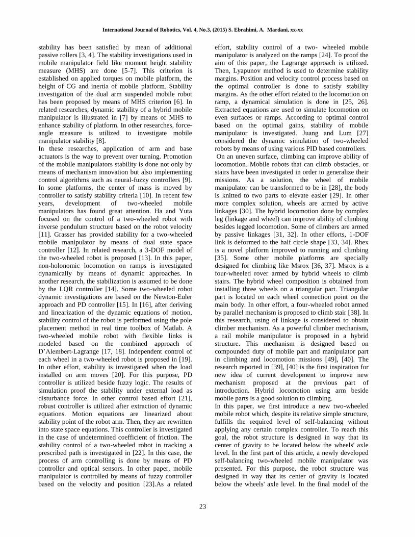
Fig. 17. This criterion demonstrates stability and
overturning prevention. A special stability point is when
the robot CG is located under wheel axis. Mobile
manipulator is permanently stable due to the results of
self-balancing part. A typical position is shown in Fig.
17 to illustrate stability margins. In this figure, 1CD and
2CD are stability margins. If they became less than zero,
the platform starts to overturn. So, all the motion
planning tasks must adopt positive amount of stability
margins.
Fig. 17. Stability margins.
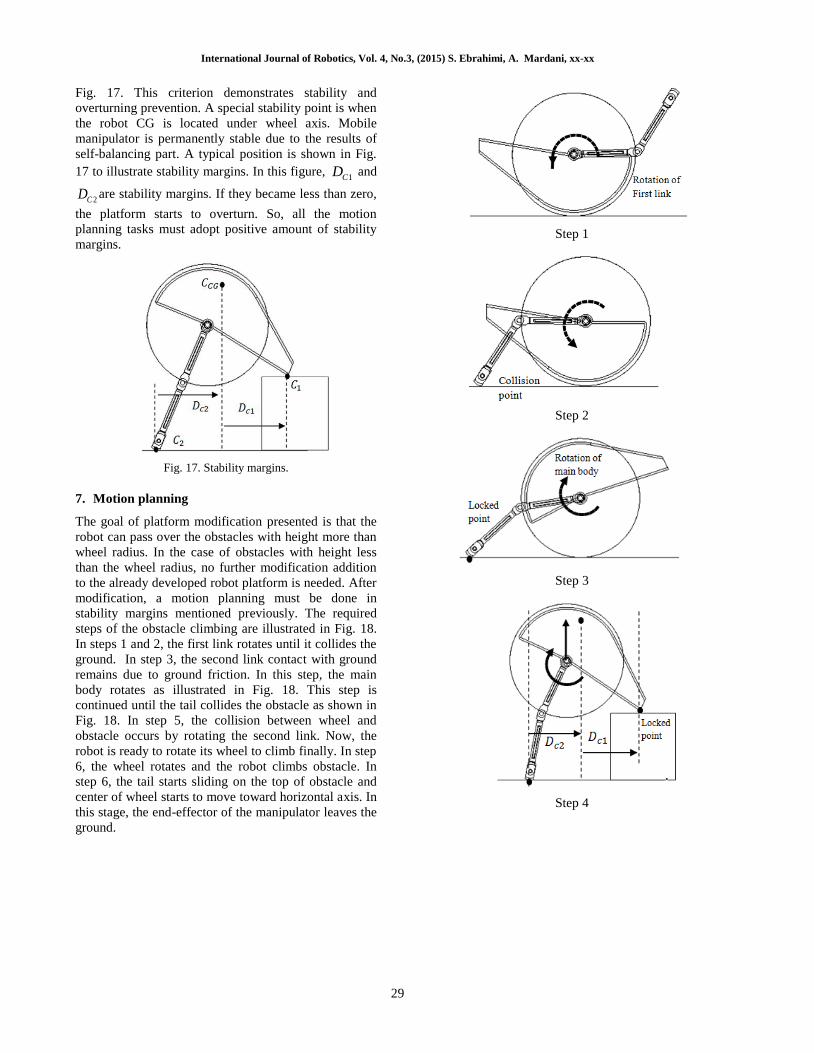
7. Motion planning
The goal of platform modification presented is that the
robot can pass over the obstacles with height more than
wheel radius. In the case of obstacles with height less
than the wheel radius, no further modification addition
to the already developed robot platform is needed. After
modification, a motion planning must be done in
stability margins mentioned previously. The required
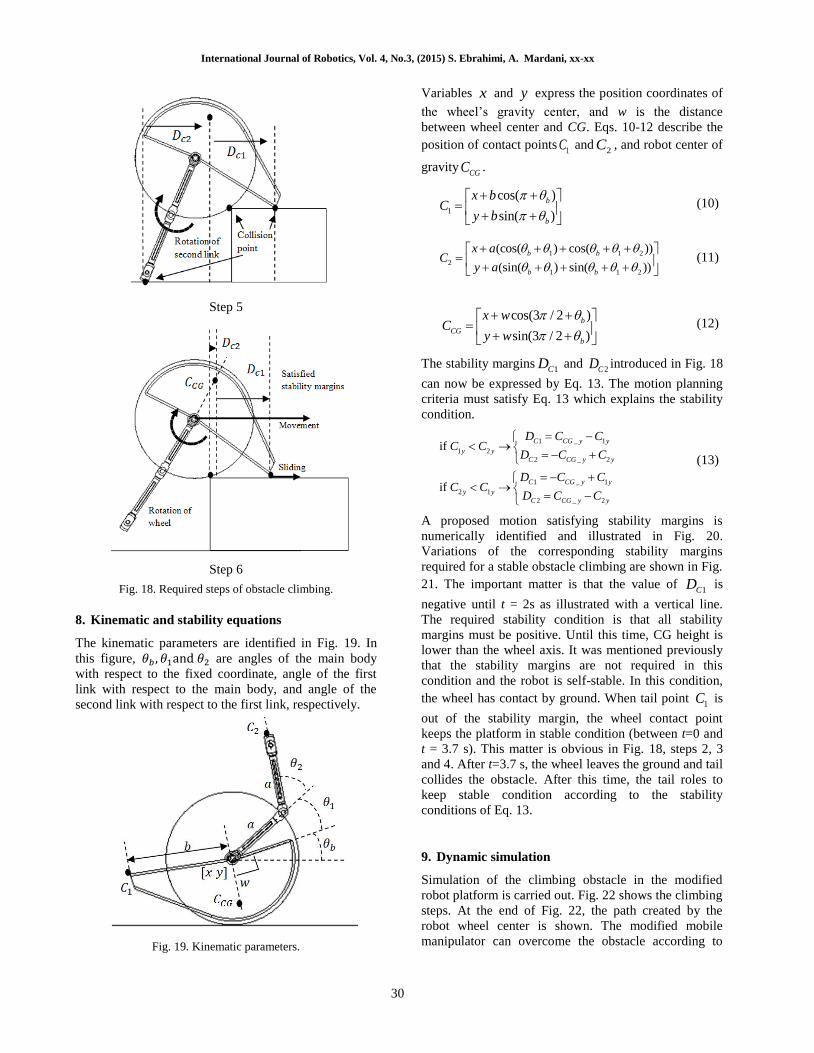
steps of the obstacle climbing are illustrated in Fig. 18.
In steps 1 and 2, the first link rotates until it collides the
ground. In step 3, the second link contact with ground
remains due to ground friction. In this step, the main
body rotates as illustrated in Fig. 18. This step is
continued until the tail collides the obstacle as shown in
Fig. 18. In step 5, the collision between wheel and
obstacle occurs by rotating the second link. Now, the
robot is ready to rotate its wheel to climb finally. In step
6, the wheel rotates and the robot climbs obstacle. In
step 6, the tail starts sliding on the top of obstacle and
center of wheel starts to move toward horizontal axis. In
this stage, the end-effector of the manipulator leaves the
ground.
Step 1
Step 2
Step 3
Step 4
International Journal of Robotics, Vol. 4, No.3, (2015) S. Ebrahimi, A. Mardani, xx-xx
30
Step 5
Step 6
Fig. 18. Required steps of obstacle climbing.
8. Kinematic and stability equations
The kinematic parameters are identified in Fig. 19. In
this figure, 𝜃𝑏 , 𝜃1and 𝜃2 are angles of the main body
with respect to the fixed coordinate, angle of the first
link with respect to the main body, and angle of the
second link with respect to the first link, respectively.
Fig. 19. Kinematic parameters.
Variables x and y express the position coordinates of
the wheel’s gravity center, and w is the distance
between wheel center and CG. Eqs. 10-12 describe the
position of contact points1C and
2C , and robot center of
gravityCGC .
1
cos( )
sin( )
b
b
x bC
y b
(10)
1 1 2
2
1 1 2
(cos( ) cos( ))
(sin( ) sin( ))
b b
b b
x aC
y a
(11)
cos(3 / 2 )
sin(3 / 2 )
b
CG
b
x wC
y w
(12)
The stability margins1CD and
2CD introduced in Fig. 18
can now be expressed by Eq. 13. The motion planning
criteria must satisfy Eq. 13 which explains the stability
condition.
1 _ 1
1 2
2 _ 2
1 _ 1
2 1
2 _ 2
if
if
C CG y y
y y
C CG y y
C CG y y
y y
C CG y y
D C CC C
D C C
D C CC C
D C C
(13)
A proposed motion satisfying stability margins is
numerically identified and illustrated in Fig. 20.
Variations of the corresponding stability margins
required for a stable obstacle climbing are shown in Fig.
21. The important matter is that the value of 1CD is
negative until t = 2s as illustrated with a vertical line.
The required stability condition is that all stability
margins must be positive. Until this time, CG height is
lower than the wheel axis. It was mentioned previously
that the stability margins are not required in this
condition and the robot is self-stable. In this condition,
the wheel has contact by ground. When tail point 1C is
out of the stability margin, the wheel contact point
keeps the platform in stable condition (between t=0 and
t = 3.7 s). This matter is obvious in Fig. 18, steps 2, 3
and 4. After t=3.7 s, the wheel leaves the ground and tail
collides the obstacle. After this time, the tail roles to
keep stable condition according to the stability
conditions of Eq. 13.
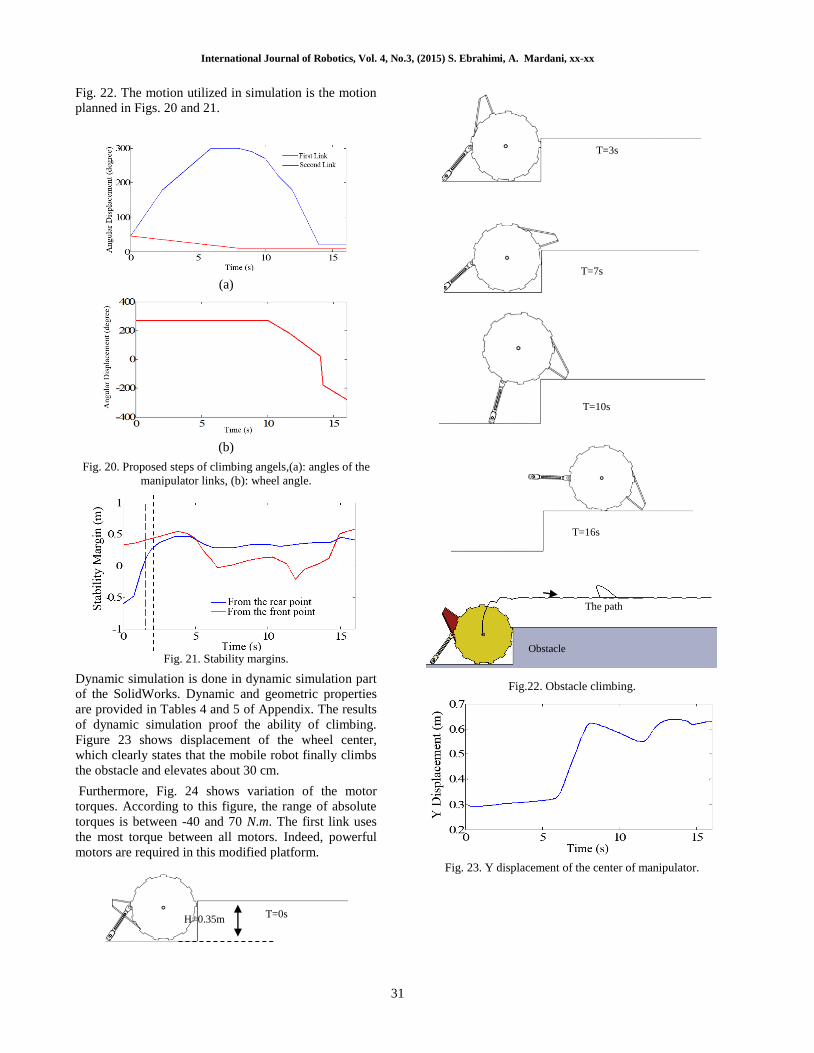
9. Dynamic simulation
Simulation of the climbing obstacle in the modified
robot platform is carried out. Fig. 22 shows the climbing
steps. At the end of Fig. 22, the path created by the
robot wheel center is shown. The modified mobile
manipulator can overcome the obstacle according to
International Journal of Robotics, Vol. 4, No.3, (2015) S. Ebrahimi, A. Mardani, xx-xx
31
Fig. 22. The motion utilized in simulation is the motion
planned in Figs. 20 and 21.
(a)
(b)
Fig. 20. Proposed steps of climbing angels,(a): angles of the
manipulator links, (b): wheel angle.
Fig. 21. Stability margins.
Dynamic simulation is done in dynamic simulation part
of the SolidWorks. Dynamic and geometric properties
are provided in Tables 4 and 5 of Appendix. The results
of dynamic simulation proof the ability of climbing.
Figure 23 shows displacement of the wheel center,
which clearly states that the mobile robot finally climbs
the obstacle and elevates about 30 cm.
Furthermore, Fig. 24 shows variation of the motor
torques. According to this figure, the range of absolute
torques is between -40 and 70 N.m. The first link uses
the most torque between all motors. Indeed, powerful
motors are required in this modified platform.
Fig.22. Obstacle climbing.
Fig. 23. Y displacement of the center of manipulator.
T=0s
T=3s
T=7s
T=10s
T=16s
H=0.35m
The path
Obstacle

International Journal of Robotics, Vol. 4, No.3, (2015) S. Ebrahimi, A. Mardani, xx-xx
32
Fig. 24. Torque of motors.
10. Conclusion
The steps of mechanical designing, primary
experimental model fabrication, and derivation of the
dynamic equations and simulations of the virtual and
real models were the main efforts done in this paper. To
obtain a proper platform, at the first step, a primary
virtual model of the new two-wheeled mobile
manipulator controlled by PID controller was designed
in Matlab Simulink (Sim-Mechanic) according to the
primary experimental model. The aim of virtual model
was detection of disadvantages of the new platform
specially fluctuation of locomotion. At the last step, two
experimental tests were carried out to proof the abilities
of the new platform in real model. In experimental test,
the maximum limits of ability in obstacle crossing and
ramp climbing was investigated besides fluctuation
monitoring. Then, the newly developed self-balancing
two-wheeled mobile manipulator of Part I of this article
was modified to climb high obstacles. The new idea is
inspired from the study results of [12] and also Part I of
this paper. According to the results, a motion was
planned satisfying stability margins during climbing
mission. The motion was applied on a virtual dynamic
model. According to the obtained results, the virtual
model followed the prescribed motion and reached top
of the obstacle. The results proof the ability of the
newly modified robot in climbing. An important matter
is that the new platform needs powerful motors to
handle missions of climbing.
References
[1] S. Zhou, Y. C. Pradeep and P. C. Chen,
“Simultaneous base and end-effector motion control of
a nonholonomic mobile manipulator”, In Automation,
Robotics and Applications (ICARA), (2015), pp. 143–
148.
[2] R. Siegwart and I. R. Nourbakhsh, “Introduction to
Autonomous Mobile Robots”, Second Edition, The MIT
Press. (2011).
[3] R. L. Williams, B. E. Carter, P. Gallina and G.
Rosati. “Dynamic Model with Slip for Wheeled Omni-
directional Robots”, IEEE Transactions on Robotics
and Automation, Vol. 18, (2002), pp. 285–293.
[4] K. Watanabe, Y. Shiraishi, S. G. Tzafestas, J. Tang
and T. Fukuda, “Feedback. Control of an
Omnidirectional Autonomous Platform for Mobile
Service Robots”, Journal of Intelligent Robotic Systems,
Vol. 22, (1998), pp. 315–30.
[5] S. A. A. Moosavian and K. Alipour, “On the
Dynamic Tip-Over Stability of Wheeled Mobile
Manipulators”, International Journal of Robotics and
Automation, Vol. 22, (2007), pp. 322–328.
[6] S. A. A. Moosavian, K. Alipour and Y.
Bahramzadeh, “Dynamics Modeling and Tip-Over
Stability of Suspended Wheeled Mobile Robots with
Multiple Arms”, Proceedings of the IEEE/RSJ
International Conference on Intelligent Robots and
Systems, San Diego, USA, (2007), pp. 1210–1215.
[7] S. A. A. Moosavian and S. S. Hoseyni, “Dynamic
Modeling and Tipover Stability of a Hybrid Serial-
Parallel Mobile Robot”, The 2nd International
Conference on Control, Instrumentation, and
Automation (ICCIA), Shiraz, Iran, (2011).
[8] C. L. Cham and W. H. Tan, “Design of an intelligent
electronic system for dump truck tip-over prevention”,
Informacije midel-journal of microelectronics
electronics components and materials, Vol. 44, (2014),
pp. 152-158.
[9] A. Ghaffari, A. Meghdari, D. Naderi and S. Eslami,
“Tip-over Stability Enhancement of Wheeled Mobile
Manipulators Using an Adaptive Neuro-Fuzzy Inference
Controller System”, International Journal of
Information and Mathematical Sciences, Vol. 5, (2009),
pp. 211–217.
[10] R. C. Ooi, “Balancing a Two-Wheeled
Autonomous Robot. Master Thesis, School of
Mechanical Engineering”, The University of Western
Australia, Crawley, (2003).

International Journal of Robotics, Vol. 4, No.3, (2015) S. Ebrahimi, A. Mardani, xx-xx
33
[11] Y. Ha and S. Yuta, “Trajectory tracking control for
navigation of the inverse pendulum type self-contained
mobile robot”, Robotics and Autonomous Systems, Vol.
17, (1996), pp. 65–80.
[12] F. Grasser, A. D’Arrigo, S. Colombi and A. C.
Rufer, “JOE: a mobile, inverted pendulum”, IEEE
Transactions in Industrial Electronics, Vol. 49, (2002),
pp. 107–114.
[13] Y. Kim, S. H. Kim and Y. K. Kwak, “Dynamic
Analysis of a Nonholonomic Two-Wheeled Inverted
Pendulum Robot”, Journal of Intelligent and Robotic
Systems, Vol. 44, (2005), pp. 25–46.
[14] W. An and Y. Li, “Simulation and Control of a
Two-wheeled Self-balancing Robot”, Proceeding of the
IEEE International Conference on Robotics and
Biomimetics (ROBIO(, Shenzhen, China, ( 2013).
[15] K. M. Goher and M. O. Tokhi, “Modeling
Simulation and Balance Control of a Two-Wheeled
Robotic Machine with Static Variation in Load
Position”, In the Proceedings of the 22nd European
Conference on Modeling and Simulation, Nicosia,
Cyprus, (2008).
[16] S. W. Nawawi, M. N. Ahmad and J. H. S. Osman,
“Real-Time Control of a Two-Wheeled Inverted
Pendulum Mobile Robot”, World Academy of Science,
Engineering and Technology, Vol. 15, (2008), pp. 214–
220.
[17] X. Raun, H. Ren, X. Li and Q. Wang, “Dynamic
Model and Analysis of the Flexible Two-Wheeled
Mobile Robot”, Intelligent Robotics and Applications,
Vol. 5314, (2008), pp. 933– 942.
[18] X. Raun and J. Zhao, “The Flexible Two-Wheeled
Self-balancing Robot based on Hopfield”, Intelligent
Robotics and Applications, Vol. 5928, (2009), pp.
1196– 1204.
[19] P. Genova, M. Mihailova, R. Oransky and D.
Ignatova, “Kinematics And Dynamics Modelling of
Two-Wheeled Robot”, 11th National Congress on
Theoretical and Applied Mechanics, 2-5 Sept.,
Borovets, Bulgaria, (2009).
[20] K. M. Goher, M. O. Tokhi and N. H. Siddique,
“Dynamic Modeling and Control of A Two Wheeled
Robotic Vehicle With A Virtual Payload”, ARPN
Journal of Engineering and Applied Sciences, Vol. 6,
(2011), pp. 7–41.
[21] L. Mollov and P. Petkov, “Embedded Robust
Control of Self-balancing Two-wheeled Robot”,
Information Technologies and Control, Vol. 4, (2011),
pp. 23–31.
[22] N. M. Abdul Ghani, F. Naim and T. P. Yon, “Two
Wheels Balancing Robot with Line Following
Capability”, World Academy of Science, Engineering
and Technology, Vol. 55, (2011), pp. 634-638.
[23] J. Wu, W. Zhang and S. Wang, “A Two-Wheeled
Self-Balancing Robot with the Fuzzy PD Control
Method”, Mathematical Problems in Engineering, Vol.
2012, Article ID 469491, (2012).
[24] K. Peng, X. Ruan and G. Zuo, “Dynamic model
and balancing control for two-wheeled self-balancing
mobile robot on the slopes”, 10th World Congress on
Intelligent Control and Automation (WCICA), Beijing,
(2012), pp. 3681 – 3685.
[25] Z. Kausar, K. Stol and N. Patel, “The Effect of
Terrain Inclination on Performance and he Stability
Region of Two-Wheeled Mobile Robots”, International
Journal of Advanced Robotic Systems, Vol. 9, (2012),
pp. 1–11.
[26] T. Tomašić, A. Demetlika ans M. Crneković, “Self-
Balancing Mobile Robot Tilter”, Transactions of
Famena, Vol.3, (2012), pp. 23–32.
[27] H. S. Juang, K. Y. Lum, “Design and Control of a
Two-Wheel Self-Balancing Robot using the Arduino
Microcontroller Board”, 10th IEEE International
Conference on Control and Automation (ICCA),
Hangzhou, China, (2013).
[28] J. M. Morrey, B. Lambrecht, , A. D. Horchler, R.
E. Ritzmann and R. D. Quinn, “Highly mobile and
robust small quadruped robots”, Intelligent Robots and
Systems, Vol. 1, (2003), pp. 82-87.
[29] A. S. Boxerbaum, P. Werk, R. D. Quinn and R.
Vaidyanathan, “Design of an autonomous amphibious
robot for surf zone operation: part I mechanical design
for multi-mode mobility”, Advanced Intelligent
Mechatronics. Proceedings, 2005 IEEE/ASME
International Conference, (2005), pp. 1459-1464.
[30] A. Halme, I. Leppänen , S. Salmi and S. Ylönen,
“Hybrid locomotion of a wheel-legged machine”, 3rd
Int. Conference on Climbing and Walking Robots,
(2000).
[31] R. Volpe, J. Balaram, T. Ohm and T. Ivlev, “The
Rocky 7 Mars Rover Prototype”, IEEE/RSJ
International Conference on Intelligent Robots and
Systems, Osaka Japan, (1996).
[32] T. Estier, Y. Crausaz, B. Merminod, M. Lauria and
R. R. Siegwart, “An innovative Space Rover with
Extended Climbing Alilities”. Proceedings of Space and
Robotics, (2000).
[33] H. Tappeiner, S. Skaff, , T. Szabo and R. Hollis,
“Remote haptic feedback from a dynamic running
machine. Robotics and Automation”, IEEE International
Conference, (2009), 2368-2373.
[34] N. Neville, M. Buehler and I. Sharf, “A bipedal
running robot with one actuator per leg. Robotics and
Automation”, ICRA (2006), pp. 848-853.
[35] S. C. Chen, K. J. Huang, W. H. Chen, S. Y. Shen,
C. H. Li and P. C Lin, “Quattroped: A Leg-Wheel
Transformable Robot”, Mechatronics, IEEE/ASME
Transactions Vol. 2, (2014), pp. 730-742.
[36] M. M. Dalvand and M. M. Moghadam, “Stair
climber smart mobile robot (MSRox)”, Autonomous
Robots, Vol. 20, (2002), pp. 3-14.

International Journal of Robotics, Vol. 4, No.3, (2015) S. Ebrahimi, A. Mardani, xx-xx
34
[37]M. M. Dalvand and M. M. Moghadam, “Design and
modeling of a stair climber smart mobile robot
(MSRox)”, ICAR Proceedings of the 11th International
Conference on Advanced Robotics, (2003), pp. 1062-
1067.
[38] O. Matsumoto, S. Kajita, K. Tani, and M. Oooto,
“A four-wheeled robot to pass over steps by changing
running control modes”, Robotics and Automation, Vol.
2, (1995), pp. 1700-1706.
[39] P. Ben-Tzvi, A. A. Goldenberg, and J. W Zu,
“Design and analysis of a hybrid mobile robot
mechanism with compounded locomotion and
manipulation capability”, Journal of Mechanical
Design, Vol. 7, (2008).
[40] P. Ben-Tzvi, S. Ito and A. Goldenberg,
“Autonomous stair climbing with reconfigurable
tracked mobile robot”, Robotic and Sensors
Environments. International Workshop, (2007), pp. 1-6.
[41] Matlab Simulink, PID control Toolbox.
Biography
Saeed Ebrahimi is currently an
associate professor of Mechanical
Engineering at Yazd University,
Iran. He has received his PhD in
Mechanical Engineering from
Stuttgart University, Germany, in
2007. He has also completed his postdoctoral
fellowship at the Center for Intelligent Machines
(CIM), McGill University in 2008. His current
research interest includes Dynamic Modelling of
Multibody Systems, Robotics, Mechanisms Design
and Vibration Analysis of Mechanical Systems.
Arman Mardani is currently a
PhD student in the Department
of Mechanical Engineering at
Yazd University. He received
his BSc in Mechanical
Engineering in 2012 from Yazd
University and his MSc in
Mechatronic Engineering in
2014 from Shahrood University. His research
interests include robotics, structural design of
robots and multibody simulations related to
multimode and mobile robots.
Appendix
Fig. 25. Matlab Simulink diagram.
Table 4. Mechanical properties
Part Property Value
Manipulator link length 0.2 m
Manipulator link mass 0.3 kg
Main body mass 20 kg
Wheel radius 0.275 m
Wheel mass 0.2 kg
Wheel width 0.03 m
Axis length 0.3 m
Table 5. Self-stable robot properties
Property Value
a 0.2 m
b 0.4 m
w 0.255 m
r 0.275 m
Link mass 0.3 kg
Wheel mass 1 kg
Main body mass 20 kg
Friction coefficient 0.45