uBot-7: A Dynamically Balancing Mobile Manipulator with ... · PDF fileuBot-7: A Dynamically...
7
uBot-7: A Dynamically Balancing Mobile Manipulator with Series Elastic Actuators Dirk Ruiken 1 , Jonathan P. Cummings 2 , Uday R. Savaria 1 , Frank C. Sup IV 2 , and Roderic A. Grupen 1 Abstract— We present the next generation of the uBot series: the uBot-7 mobile manipulator with 14 degrees of freedom, 95 cm tall, weighing about 27 kg. The robot is a new, unique mobile manipulator with great versatility to solve tasks in mobility and manipulation. The design is based on experiences from previous uBot generations. We detail the mechanical and electrical layout and highlight the improvements with regards to its predecessor uBot-6. All arm and torso joints are driven by series elastic actuators (SEAs) for better sensing and safer interaction around humans. This makes it the first wheeled dynamic balancer with SEAs. Upgrades to stronger brushless DC motors improve the strength of the robot more than twofold. The head has been extended with two additional motors and now offers independent viewpoint control of the RGB-D camera for all postural configurations of the robot. Finally, a new drive train removes backlash from the base wheels while providing more torque and speed. The design of the robot will be released as open-source. I. INTRODUCTION AND RELATED WORK Mobile manipulators are increasingly expected to work in human environments. Research in this area is often con- ducted with statically stable wheeled robots, such as PR2 and ARMAR-III, that have upper bodies equipped with arms and grippers to interact with the environment [1, 2]. These robots can access most human environments that are wheelchair accessible, but they rely on heavy bases with large footprints to ensure static stability even when reaching for objects far away from the body and when maneuvering at moderate to high speeds. Dynamically stable robots constantly balance to maintain stability, but require a much smaller footprint and support easier movement in cluttered environments and crowds. Legged humanoids, such as Asimo and ARMAR-4, fall into this category even though they can be statically stable at times [3, 4]. To avoid the complexity of legs on the mechanism in design and control, robots such as the uBot series, Ballbot, and Golem Krang balance on two wheels or a ball to maintain dynamic stability [5–9]. The use of wheels is also much more energetically efficient than the use of legs as the own weight does not have to be carried, and balancing requires very little energy [7]. Additionally, dynamic stability can improve performance in tasks like pushing and lifting as 1 Dirk Ruiken, Uday Savaria, and Roderic A. Grupen are affiliated with the Laboratory for Perceptual Robotics, College of Information and Computer Sciences, University of Massachusetts Amherst, USA, [email protected], [email protected], [email protected] 2 Jonathan P. Cummings and Frank C. Sup IV are affiliated with the Department of Mechanical and Industrial Engineering, Uni- versity of Massachusetts Amherst, USA, [email protected], [email protected] the body mass can be used more effectively [5, 10, 11]. This, however, comes at the cost of having to prevent or control possible falls. Fig. 1. The uBot-7 mobile manipulator: a dynamically stable robot with 14 active degrees of freedom, 10 series-elastic joints, 27 kg and 95 cm. The uBot series has been developed as a unique design point combining many advantageous properties into a single robot platform: the uBots have been designed to be large and strong enough to manipulate objects in the real world, yet be small and lightweight enough to be operated easily without complex safety harnesses. At toddler size, the arms can reach table-tops as well as the ground. The small size also makes the robot less intimidating and keeps cost low. Dynamic balancing on two wheels is used to combine great energy efficiency and a small footprint with reduced mechanical and control complexity. Balancing also provides low input impedance longitudinally, making it a good design consider- ation for safety. Stiff platform impedance laterally supports high manual precision within the bimanual workspace of the robot. Its design avoids highly expensive components, such as harmonic drive gears, in order to keep the robot low cost (for a robot with comparable capabilities) while achieving good performance for manipulation and locomotion. Based on the concept of having ‘many solutions for many problems,’ the uBot series is a mechanical commitment to solving problems in unstructured environments. For example,
Transcript of uBot-7: A Dynamically Balancing Mobile Manipulator with ... · PDF fileuBot-7: A Dynamically...

uBot-7: A Dynamically Balancing Mobile Manipulatorwith Series Elastic Actuators
Dirk Ruiken1, Jonathan P. Cummings2, Uday R. Savaria1, Frank C. Sup IV2, and Roderic A. Grupen1
Abstract— We present the next generation of the uBot series:the uBot-7 mobile manipulator with 14 degrees of freedom,95 cm tall, weighing about 27 kg. The robot is a new, uniquemobile manipulator with great versatility to solve tasks inmobility and manipulation. The design is based on experiencesfrom previous uBot generations. We detail the mechanical andelectrical layout and highlight the improvements with regardsto its predecessor uBot-6. All arm and torso joints are drivenby series elastic actuators (SEAs) for better sensing and saferinteraction around humans. This makes it the first wheeleddynamic balancer with SEAs. Upgrades to stronger brushlessDC motors improve the strength of the robot more than twofold.The head has been extended with two additional motors andnow offers independent viewpoint control of the RGB-D camerafor all postural configurations of the robot. Finally, a new drivetrain removes backlash from the base wheels while providingmore torque and speed. The design of the robot will be releasedas open-source.
I. INTRODUCTION AND RELATED WORK
Mobile manipulators are increasingly expected to workin human environments. Research in this area is often con-ducted with statically stable wheeled robots, such as PR2 andARMAR-III, that have upper bodies equipped with arms andgrippers to interact with the environment [1, 2]. These robotscan access most human environments that are wheelchairaccessible, but they rely on heavy bases with large footprintsto ensure static stability even when reaching for objects faraway from the body and when maneuvering at moderate tohigh speeds.
Dynamically stable robots constantly balance to maintainstability, but require a much smaller footprint and supporteasier movement in cluttered environments and crowds.Legged humanoids, such as Asimo and ARMAR-4, fallinto this category even though they can be statically stableat times [3, 4]. To avoid the complexity of legs on themechanism in design and control, robots such as the uBotseries, Ballbot, and Golem Krang balance on two wheels ora ball to maintain dynamic stability [5–9]. The use of wheelsis also much more energetically efficient than the use of legsas the own weight does not have to be carried, and balancingrequires very little energy [7]. Additionally, dynamic stabilitycan improve performance in tasks like pushing and lifting as
1Dirk Ruiken, Uday Savaria, and Roderic A. Grupen are affiliatedwith the Laboratory for Perceptual Robotics, College of Informationand Computer Sciences, University of Massachusetts Amherst, USA,[email protected], [email protected],[email protected]
2Jonathan P. Cummings and Frank C. Sup IV are affiliatedwith the Department of Mechanical and Industrial Engineering, Uni-versity of Massachusetts Amherst, USA, [email protected],[email protected]
the body mass can be used more effectively [5, 10, 11]. This,however, comes at the cost of having to prevent or controlpossible falls.
Fig. 1. The uBot-7 mobile manipulator: a dynamically stable robot with14 active degrees of freedom, 10 series-elastic joints, 27 kg and 95 cm.
The uBot series has been developed as a unique designpoint combining many advantageous properties into a singlerobot platform: the uBots have been designed to be large andstrong enough to manipulate objects in the real world, yet besmall and lightweight enough to be operated easily withoutcomplex safety harnesses. At toddler size, the arms can reachtable-tops as well as the ground. The small size also makesthe robot less intimidating and keeps cost low. Dynamicbalancing on two wheels is used to combine great energyefficiency and a small footprint with reduced mechanicaland control complexity. Balancing also provides low inputimpedance longitudinally, making it a good design consider-ation for safety. Stiff platform impedance laterally supportshigh manual precision within the bimanual workspace of therobot. Its design avoids highly expensive components, suchas harmonic drive gears, in order to keep the robot low cost(for a robot with comparable capabilities) while achievinggood performance for manipulation and locomotion.
Based on the concept of having ‘many solutions for manyproblems,’ the uBot series is a mechanical commitment tosolving problems in unstructured environments. For example,

Fig. 2. Examples of three statically stable postural configurations of uBot-7: four point contact with elbow and base wheels at low body height (left) andhigh body height (middle) support alternative forms of mobility with reduced manipulation capabilities; lying prone provides maximal stability and leavesthe arms free for manipulation (right).
uBot-6 added different postural configurations [7]. Each con-figuration supports different properties to both manipulationand mobility (Fig. 3). Transitioning to a statically stableconfiguration can greatly increase manual precision andenable successful completion of otherwise impossible tasks.Likewise, different postural configurations also support dif-ferent forms of mobility that can help overcome obstacles inthe environment and make areas without smooth flat groundaccessible [12]. The previous two models of the uBot series,uBot-5 and uBot-6, have been used successfully in many ap-plications ranging from object recognition/manipulation [13],autonomous assembly [14, 15], emergency response [16],and physical rehabilitation [17, 18].
Fig. 3. Transitions between postural configurations and the respectivemodes of mobility. Balancing is highly energy efficient, but requires arelatively flat ground. Knuckle-walking enables traversing rough terrain byusing the arm for walking. Prone-scooting supports statically stable mobilityat a lower body height by using passive wheels on the elbows.
With advances in mobile manipulation, interest is increas-ing in robots working side by side with humans. Safetyis the main concern in such scenarios. Accidental impactswith humans should have minimal potential of injuring themand need to be detected by the robot. The most popularmethod to implement this functionality in robots is the useof impedance control [19]. This can either be done on robotswith series elastic actuators (SEAs) [20] with passive com-pliance at the expense of precision, for example Baxter andCOMAN [21, 22], or on robots with high performance torque
sensing capabilities, for example DLR’s Justin [23, 24].uBot-7 (Fig. 1) has been developed to incorporate SEAs
into a versatile platform such as predecessor uBot-6. Itis a toddler-sized mobile manipulator with 14 degrees offreedom (DOF). It has two 4-DOF arms, a rotatable trunk,and a 3-DOF head. The robot weighs about 27 kg and is95 cm tall. In its primary form of locomotion the robot is adynamic balancer on two wheels. The wheels provide non-holonomic drive capabilities with differential steering. Justlike uBot-6, it is capable of transitioning to and betweenother postural configurations (Fig. 2) [7]. Each posturalconfiguration enables additional ways to interact with theenvironment and solve tasks. At the same time they also poseadditional requirements to the robot design. A new improvedhead mechanism accommodates many of these requirementsin order to extend the capabilities to interact with theenvironment and solve tasks in any postural configuration.The addition of SEAs to all arms and torso joints extendsthe passive, anisotropic impedance character of its base intoan active impedance character in the upper body.
The experience with predecessor uBot-6 resulted in twoarchitectural changes:
• All arm and torso joints are driven by SEAs that supportimpedance control for safer operation near humans. TheSEAs also provide force/torque sensing for better ma-nipulation capabilities. Additionally, the passive proper-ties of SEAs combined with reactive control can protectgearheads from damage in case of a fall. A modularSEA module was developed for uBot-7 [25–27].
• The head has been extended with two more activedegrees of freedom to support full pan-tilt view ofthe entire robot workspace that is independent of thepostural configuration. Previously, this capability wasonly available while balancing and required the use ofthe trunk rotation.
A number of smaller improvements include:• Motors were switched from brushed DC to brushless
DC (BLDC) motors resulting in about twofold increasein strength.
• Backlash in the wheel drive train can cause problemswhile balancing. An improved drive train eliminatesbacklash while increasing wheel torque and speed.
• The control architecture was switched to a decentral-ized strategy, removing harness complexity, alleviating
difficulty of cable routing, and reducing possible failurepoints (connectors).
The main contribution of this paper is the presentation ofthe complete design of the new, unique mobile manipulator,uBot-7. The base structure and the SEA modules have beenpreviously documented [25, 26]. This paper presents the fullyintegrated robot platform with embedded systems, sensors,and control architecture. To our knowledge it is the first dy-namically balancing wheeled mobile manipulator with SEAs.Its design has been evolved over many robot generationsto combine many advantages from different areas into asingle platform. It offers a unique versatility to solve tasksin mobility and manipulation while being low cost and easyto operate. The design of uBot-7 will be made open-sourceand available on http://lpr.cs.umass.edu/ubot inhopes to enable other researchers with the capabilities of thisplatform.
The mechatronic design of uBot-7 will be presented inSection II. Emphasis is given to details that have been im-proved from previous models. Section III describes the motorcontrol system, sensors, the available computing hardware,and the interprocess communication architecture. We conludein Section IV and outline future work.
II. MECHATRONIC DESIGN
The mechanical design can be separated into three differ-ent parts: the head, arms and torso, and the wheeled base.In the following sections, we present details of each part,highlighting the improvements based on experiences fromwork with uBot-4/5/6 [5–7, 27].
A. Head
The head design is based on experiences from uBot-6 [7].The head of uBot-6 uses two coupled joints driven by a singleactuator to enable compensation of different body angles dueto dynamic balancing as well as different postural modes(Fig. 4). Paning capabilities could be performed by rotatingthe torso though this is only available while balancingupright. Additionally, it enables moving the camera forwardto provide an unobstructed view of the space in front of therobot.
Fig. 4. Examples of different requirements for camera direction: uprightbalancing (left), unobstructed view of the manual workspace (middle), four-point contact postural configuration for prone scooting (right) [7].
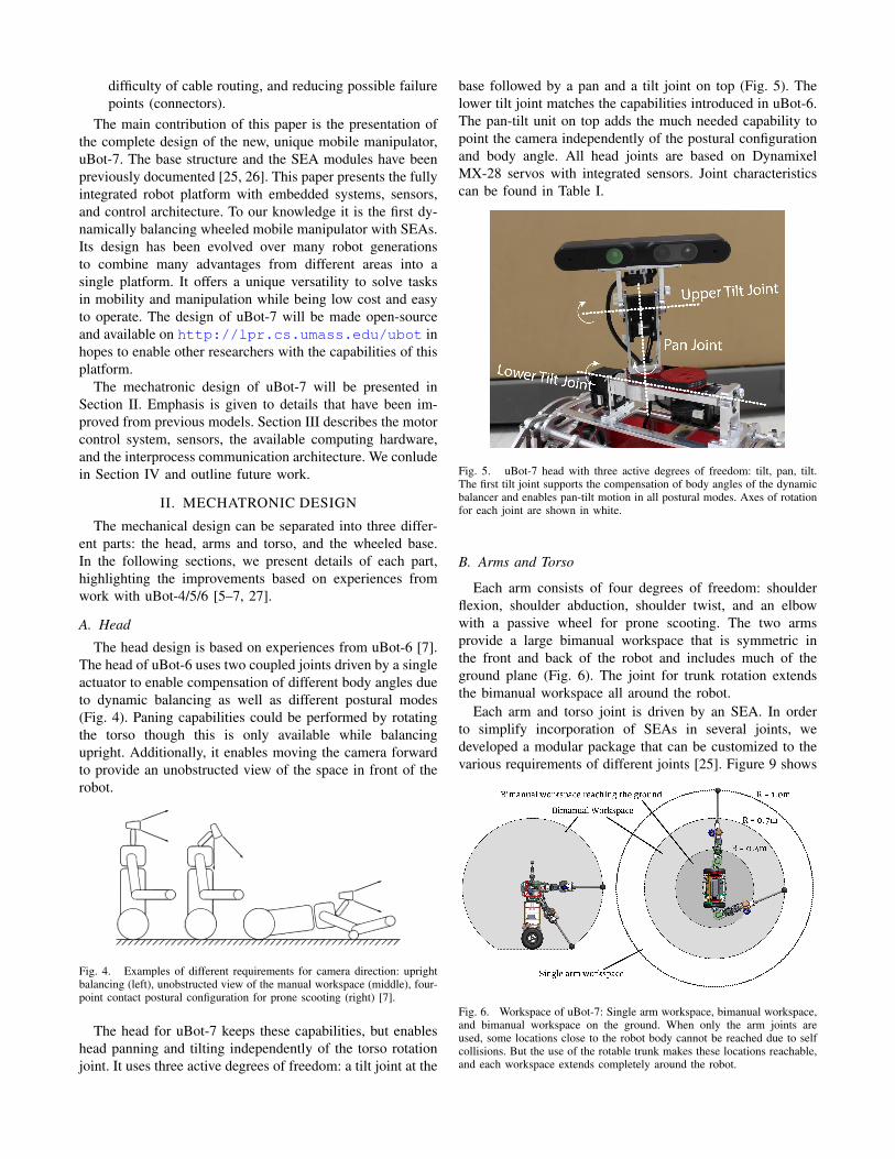
The head for uBot-7 keeps these capabilities, but enableshead panning and tilting independently of the torso rotationjoint. It uses three active degrees of freedom: a tilt joint at the
base followed by a pan and a tilt joint on top (Fig. 5). Thelower tilt joint matches the capabilities introduced in uBot-6.The pan-tilt unit on top adds the much needed capability topoint the camera independently of the postural configurationand body angle. All head joints are based on DynamixelMX-28 servos with integrated sensors. Joint characteristicscan be found in Table I.
Fig. 5. uBot-7 head with three active degrees of freedom: tilt, pan, tilt.The first tilt joint supports the compensation of body angles of the dynamicbalancer and enables pan-tilt motion in all postural modes. Axes of rotationfor each joint are shown in white.
B. Arms and Torso
Each arm consists of four degrees of freedom: shoulderflexion, shoulder abduction, shoulder twist, and an elbowwith a passive wheel for prone scooting. The two armsprovide a large bimanual workspace that is symmetric inthe front and back of the robot and includes much of theground plane (Fig. 6). The joint for trunk rotation extendsthe bimanual workspace all around the robot.
Each arm and torso joint is driven by an SEA. In orderto simplify incorporation of SEAs in several joints, wedeveloped a modular package that can be customized to thevarious requirements of different joints [25]. Figure 9 shows
Fig. 6. Workspace of uBot-7: Single arm workspace, bimanual workspace,and bimanual workspace on the ground. When only the arm joints areused, some locations close to the robot body cannot be reached due to selfcollisions. But the use of the rotable trunk makes these locations reachable,and each workspace extends completely around the robot.

TABLE IJOINT CHARACTERISTICS FOR UBOT-6 AND UBOT-7
Continuous torque [Nm] Max. angular speed [deg/s] Range of Motion [deg] MotorsuBot-6 uBot-7 uBot-6 uBot-7 uBot-7 uBot-7
Head Upper Tilt – 0.6 – 400 [ -90, 90] Dynamixel MX-28Pan – 0.6 – 400 [-200, 200] Dynamixel MX-28Lower Tilt 0.6 0.6 850 400 [ -90, 90] Dynamixel MX-28
Torso 2.6 12.0 570 234 [-165, 165] Maxon ECflat 45 (70W)Shoulder Roll 15.0 45.0 100 114 [-360, 360] Maxon ECflat 90 (90W)
Pitch 6.4 21.0 237 162 [ -30, 180] Maxon ECflat 45 (70W)Yaw 6.4 12.0 237 234 [ -80, 260] Maxon ECflat 45 (70W)
Elbow 6.4 12.0 237 234 [ -60, 100] Maxon ECflat 45 (70W)Wheel 2.4 4.2 900 1900 continuous Maxon ECflat 90 (90W)
the different arm joints equipped with the modular SEAs.Figure 7 shows a detailed view of the modular SEA in theshoulder abduction joint. Each SEA module combines flatbrushless DC (BLDC) motors, planetary gearheads, and flattorsional spring designs in order to remain lightweight, low-volume, easy to reconfigure, and high performing. The springdesign (Fig. 8) has a linear torque-displacement relationship.It was developed in collaboration with partners at the JohnsonSpace Center and is similar to the spring design used inNASA’s Robonaut 2 [28, 29].
Absolute position sensors measure the position of thejoint output at high resolution. Joint torque is determinedby measuring the deflection of the torsional spring directlywith a Hall effect sensor providing an extremely cheap sensorwith decent resolution (see [25] for a detailed discussion).
All components of the SEA module (except the springs)are commercially available and affordable enough to matchthe low-cost principle of the uBot series. The spring designis based on two-dimensional cutting operations and can bemachined easily.
The experiences with uBot-5 and uBot-6 were used toselect appropriate joint torques, velocities, and ranges ofmotion (see Table I). The velocity requirements are basedon the need to execute bracing actions in case of a potentialfall. As the robot can knuckle-walk with its arms, it needsto be strong enough to support its body weight. The rangeof motions were chosen to provide the large bimanualworkspace all around the robot.
Fig. 7. Components of the SEA for shoulder abduction. The mo-tor/gearhead output shaft is connected to the center of a torsional springand the outside of the spring is connected to the link of the joint. A Halleffect sensor measures the displacement of a magnet to measure the springdeflection.
As the uBot can balance on a differentially steered, two-wheeled base and may fall, the resulting loads on the armsmay exceed normal design loads. The passive properties ofSEAs combined with reactive control can protect gearheadsfrom damage. A larger passive compliance is desired toprovide enough reaction time for actively moving joints outof the way and gracefully absorbing impacts once an impactis detected. A larger maximum spring deflection also im-proves the sensing resolution, but makes precise control moredifficult. Therefore, we chose a maximum spring deflectionof ±4 deg as a trade-off between manual precision and torquesensing resolution. The spring constants for each joint werechosen based on maximum joint torque and the maximumspring deflection. This results in sensing resolutions between0.011 Nm (elbow) and 0.044 Nm (shoulder). The springconstant of the used springs is linear in the thickness of thespring. Thus the spring constants can easily be changed byinstalling thicker or thinner springs.
C. Drive System
The main drawback of the uBot-6 drive system has beenthe presence of backlash in the gearheads of the drive motors.As balancing requires frequent direction changes just atthe equilibrium point, this backlash can be very noticeable.With every direction change, the gear first moves throughthe backlash region before providing torque in the otherdirection. As a result, wheel chattering can occur whenstanding still and only small wheel corrections are required.
Fig. 8. Torsional spring design with a linear torque-displacement relation-ship used in the modular SEAs.

Fig. 9. Rendering of an arm consisting of four four joints equipped withSEAs.
This issue has been addressed in a new drive train designfor uBot-7. Powerful 90 W flat BLDC motors provide muchhigher torque to the drive wheels and thus only a very smalladditional gear reduction is needed. We use timing belts toprovide a backlash-free 7.5:1 gear reduction to the wheels.The change roughly doubles available continuous torque,maximum torque, and maximum velocity while removingbacklash issues. A special embedded control board (SectionIII-A) was designed to handle control of both wheel motorsas well as measurements from inertial measurement units(IMUs) to ensure all resources required for balancing are inone place.
III. CONTROL ARCHITECTURE
uBot-6 employs a centralized motor control strategy andcontrols all joints from a single field programmable gatearray (FPGA). On uBot-7, motor controllers are distributedover the whole robot and placed close to the respectivejoints. Sensors and motors are interfaced locally, and onlya communication bus and power need to be routed. As aresult only a small number of cables run through the arms,simplifying routing. The freed space in the torso can houseadditional on-board computing hardware. Up to six lithiumiron phosphate (LiFePO4) battery packs can be housed in thetrunk of the robot. The operation time of the robot on thesebatteries has not been tested yet, but uBot-6 could operateabout one hour on two battery packs. It is important to notethat the power consumption is heavily dominated by the on-board computer. Under full processing load the computerneeds 45 W while the remainder of the robot only consumes2.6 W while just balancing.
A. Motor Control System
The arms, torso, and wheels are driven by brushless DCmotors (BLDC). Custom embedded controller boards for mo-
tor control and sensor processing are distributed throughoutthe body in proximity of the respective joints. The customPCBs are built around Maxon ESCON 50/5 motor controlmodules. A PIC32MX 80 MHz microcontroller interfacesthe motor control modules, sensors, and the communicationbus. It currently supports position, velocity, torque, andimpedance control at 1 KHz control rate and allows fullaccess to extend the programming.
We designed two different custom controller boards thatare able to control one or two joints: All arm joints as wellas the torso joint are each equipped with a single embeddedcontroller board per joint. Both wheel motors share a singlecontroller board with two motor driver modules. This con-troller board also directly interfaces two inertial measurementunits (IMUs). By combining all sensor input, computation,and motor control needed for balancing on a single embeddedcontroller board, balancing control becomes independent ofpossible problems with the control computer or board-to-board communication. The control computer calculates shiftsin the center of mass of the robot based on all joint anglesand passes them as parameters to the balancer running onthe embedded hardware.
B. Sensors
The robot is equipped with a wide range of sensors(Table II). All arm and torso joints are driven by SEAs.Each uses a Hall effect sensor to determine joint torqueby measuring the deflection of the torsional spring. Jointoutput positions are measured with absolute position sensorsat high resolution (10-13 bpr). Several joints have a largerrange of motion than could be handled by a single absoluteposition sensor at the desired resolution. Therefore, twoabsolute position sensors are combined with two differentgear reductions. The phase difference between the sensorsignals supports calculation of a high resolution absoluteposition over the whole range of motion. The same methodalso enables acquiring a high resolution measurement fromtwo (cheaper) low resolution sensors [25]. The wheel motorsare not driven by SEAs, and an incremental position encoderat the motor provides sufficient feedback. Both wheels arecontrolled by a single microcontroller that uses the feedbackof an onboard IMU chip to perform balancing control. Anadditional external IMU placed near the robot’s center ofmass can be connected directly to provide more robust-ness to external disturbances and impacts. All embeddedcontroller boards also provide current sensing. The headjoints use Dynamixel servo motors that provide feedback ofjoint positions, velocities, and torques. An Asus Xtion ProLive mounted on the head delivers RGB-D information at30 Hz [30]. In the future, both arms will be equipped with6-DOF force/torque sensors.
C. PC System
The robot is equipped with two on-board computers. Anembedded pico-ITX computer with a quad-core 6th genera-tion 2.6 GHz Intel Core-i7 processor is housed in the baseof the robot. It handles communication with the distributed

TABLE IISENSORS OF UBOT-7
Sensor Type Manufacturer Position QuantityIMU BM055 Bosch Base, Torso 2Absolute encoders MA3 US Digital Arms, torso 14Incremental encoders MILE Maxon Wheel motors 2Current sensing Escon 50/5 Maxon Arms, torso, wheels 11Torque sensor 90363 Melexis Arms, torso, 9Position sensor MX-28 Dynamixel Head 36 DOF force/torque Mini45 ATI Wrists 2Camera/RGB-D Xtion Pro Live Asus Head 1
motor controller and sensor boards and any Cartesian control.Additionally, it can perform high-level planning and control.A Jetson TX1 board adds capabilities for GPU acceleratedprocessing for applications like vision, planning, and deeplearning [31, 32]. Additional space is available to add morecompute hardware to the robot in the future.
D. Communication
An overview of the compute and communication archi-tecture used on uBot-7 is shown in Figure 10. The on-board computers communicate over Gigabit Ethernet. Amini-router provides reliable WiFi connectivity for all on-board computers with the ability to secure all off-boardcommunication through a virtual private network (VPN).
The distributed motor controllers for wheels, arms, andtorso are connected to the control computer through a RS-485communication bus running at 10 Mbps which is fast enoughto support real-time control. The head motors are connectedthrough another RS-485 bus running at 2 Mbps.
The ASUS Xtion Pro Live sensor is connected throughUSB to the vision computer. A software interface exists forthe robot operating system (ROS) that supports interfacingto all joints and sensors of the robot for easy applicationdevelopment [33]. The interface is compatible with previousuBot versions and existing applications will transfer to thenew robot with minimal changes.
Jetson TX1Vision / GPU
ControlComputer
Intel Core-i7Quad Core
(Base)
Mini Router
Head Motor
Motor Control / Sensor Board
Motor Control / Sensor Board
Motor
SEA Joint Sensors
Motor
Joint Sensors
Motor
Joint Sensors
IMU (Base)
IMU (Torso)
RS-485
RS-485
RGB-D Camera
Wheels
Torso, Arms
USB
GigabitEthernet
F/T InterfaceBoard
F/T Sensor
UnusedComputer
Slot
Fig. 10. Computer and communication architecture of uBot-7.
IV. CONCLUSION AND FUTURE WORK
We presented uBot-7, the newest member of the uBotseries of mobile manipulators. To our knowledge, this is thefirst wheeled dynamic balancer with series elastic actuators(SEAs). The SEAs will provide increased performance formanipulation tasks, safety mechanisms for the robot in caseof falls, and the ability to detect accidental collisions towork around humans more safely. The capability of changingpostural configurations and mobility modes enables operationoutside of areas with flat and smooth floors. Added degreesof freedom in the head support much better perceptualperformance that is independent of these postural configu-rations. The overall design of uBot-7 adds great versatilityto solve tasks in manipulation and mobility over its prede-cessor uBot-6. The design of uBot-7 will be open-sourceand available at http://lpr.cs.umass.edu/ubot inhopes to enable other researchers with the capabilities of thisplatform.
Implementation and tests of the low-level control havebeen completed, and full operation is expected soon. Futurework will focus on transferring existing capabilities for dex-terous manipulation and mobility from uBot-6. Additionally,we will focus on investigating better manipulation strategiesbased on the improved control and sensing capabilities. Sev-eral hands have already been prototyped that could increasethe capabilities for manual interaction while being capable ofsupporting the weight of the robot during knuckle-walkingwithout damaging hands or fingers.
ACKNOWLEDGMENT
We thank Oliver Fyler for his work on the head prototype.This material is based upon work supported under GrantNASA-GCT-NNX12AR16A. Any opinions, findings, con-clusions, or recommendations expressed in this material aresolely those of the authors and do not necessarily reflect theviews of the National Aeronautics and Space Administration.
REFERENCES
[1] J. Bohren, R. B. Rusu, E. G. Jones, E. Marder-Eppstein,C. Pantofaru, M. Wise, L. Mosenlechner, W. Meeussen, andS. Holzer, “Towards autonomous robotic butlers: Lessonslearned with the PR2,” in 2011 IEEE International Conferenceon Robotics and Automation (ICRA),. IEEE, 2011, pp. 5568–5575.
[2] T. Asfour, K. Regenstein, P. Azad, J. Schroder, and R. Dill-mann, “ARMAR-III: A humanoid platform for perception-action integration,” in Proc., International Workshop on

Human-Centered Robotic Systems (HCRS), Munich. Citeseer,2006, pp. 51–56.
[3] Y. Sakagami, R. Watanabe, C. Aoyama, S. Matsunaga, N. Hi-gaki, and K. Fujimura, “The intelligent ASIMO: Systemoverview and integration,” in IEEE/RSJ International Confer-ence on Intelligent Robots and Systems, 2002., vol. 3. IEEE,2002, pp. 2478–2483.
[4] T. Asfour, J. Schill, H. Peters, C. Klas, J. Bucker, C. Sander,S. Schulz, A. Kargov, T. Werner, and V. Bartenbach,“ARMAR-4: A 63 DOF torque controlled humanoid robot,” in2013 13th IEEE-RAS International Conference on HumanoidRobots (Humanoids). IEEE, 2013, pp. 390–396.
[5] P. Deegan, B. J. Thibodeau, and R. Grupen, “Designing aself-stabilizing robot for dynamic mobile manipulation,” DTICDocument, Tech. Rep., 2006.
[6] S. Kuindersma, E. Hannigan, D. Ruiken, and R. Grupen,“Dexterous mobility with the uBot-5 mobile manipulator,” inInternational Conference on Advanced Robotics 2009 (ICAR),2009, pp. 1–7.
[7] D. Ruiken, M. W. Lanighan, and R. A. Grupen, “Posturalmodes and control for dexterous mobile manipulation: TheUMass uBot concept,” in Proc. of IEEE-RAS Int. Conf. onHumanoid Robots (Humanoids), 2013.
[8] T. Lauwers, G. A. Kantor, and R. Hollis, “A dynamicallystable single-wheeled mobile robot with inverse mouse-balldrive,” in Robotics and Automation, 2006. ICRA 2006. Pro-ceedings 2006 IEEE International Conference on. IEEE,2006, pp. 2884–2889.
[9] M. Stilman, J. Olson, and W. Gloss, “Golem Krang: Dynami-cally stable humanoid robot for mobile manipulation,” in 2010IEEE International Conference on Robotics and Automation(ICRA). IEEE, May 2010, pp. 3304–3309.
[10] P. Kolhe, N. Dantam, and M. Stilman, “Dynamic pushingstrategies for dynamically stable mobile manipulators,” in2010 IEEE International Conference on Robotics and Automa-tion (ICRA),. IEEE, 2010, pp. 3745–3750.
[11] S. R. Kuindersma, R. A. Grupen, and A. G. Barto, “Variablerisk control via stochastic optimization,” The InternationalJournal of Robotics Research, vol. 32, no. 7, pp. 806–825,2013.
[12] D. Ruiken, M. W. Lanighan, and R. A. Grupen, “Path plan-ning for dexterous mobility,” in International Conference onAutomated Planning and Scheduling (ICAPS), 2014.
[13] D. Ruiken, J. M. Wong, T. Q. Liu, M. Hebert, T. Takahashi,M. W. Lanighan, and R. A. Grupen, “Affordance-based activebelief: Recognition using visual and manual actions,” in 2016IEEE/RSJ International Conference on Intelligent Robots andSystems (IROS). IEEE, 2016, pp. 5312–5317.
[14] D. Ruiken, T. Q. Liu, T. Takahashi, and R. A. Grupen, “Re-configurable tasks in belief-space planning,” in 2016 IEEE-RAS 16th International Conference on Humanoid Robots(Humanoids). IEEE, 2016, pp. 1257–1263.
[15] R. A. Grupen, M. W. Lanighan, and T. Takahashi, “Hybridtask planning grounded in belief: Constructing physical copiesof simple structures,” in International Conference on Auto-mated Planning and Scheduling (ICAPS), 2017.
[16] H.-T. Jung, T. Takahashi, and R. Grupen, “Human-robotemergency response-experimental platform and preliminarydataset,” DTIC Document, Tech. Rep., 2014.
[17] H.-T. Jung, J. Baird, Y.-K. Choe, and R. A. Grupen, “Upperextremity physical therapy for stroke patients using a generalpurpose robot,” in RO-MAN, 2011 IEEE. IEEE, 2011, pp.270–275.
[18] H.-T. Jung, T. Takahashi, Y.-K. Choe, J. Baird, T. Foster,and R. A. Grupen, “Towards extended virtual presence of thetherapist in stroke rehabilitation,” in 2013 IEEE InternationalConference on Rehabilitation Robotics (ICORR). IEEE, 2013,pp. 1–6.
[19] N. Hogan, “Impedance control - An approach to manipulation.I - Theory. II - Implementation. III - Applications,” ASMETransactions Journal of Dynamic Systems and MeasurementControl B, vol. 107, pp. 1–24, Mar. 1985.
[20] G. A. Pratt and M. M. Williamson, “Series elastic actuators,”in Proceedings. 1995 IEEE/RSJ International Conference onIntelligent Robots and Systems 95.’Human Robot Interactionand Cooperative Robots’, vol. 1. IEEE, 1995, pp. 399–406.
[21] R. Robotics. (2017) Baxter Collaborative Robots for IndustrialAutomation. [Online]. Available: http://www.rethinkrobotics.com/baxter/
[22] N. G. Tsagarakis, S. Morfey, G. M. Cerda, L. Zhibin, andD. G. Caldwell, “Compliant humanoid COMAN: Optimaljoint stiffness tuning for modal frequency control,” in 2013IEEE International Conference on Robotics and Automation(ICRA). IEEE, 2013, pp. 673–678.
[23] C. Ott, O. Eiberger, W. Friedl, B. Bauml, U. Hillenbrand,C. Borst, A. Albu-Schaffer, B. Brunner, H. Hirschmuller,S. Kielhofer, et al., “A humanoid two-arm system for dex-terous manipulation,” in 2006 6th IEEE-RAS InternationalConference on Humanoid Robots. IEEE, 2006, pp. 276–283.
[24] T. Wimbock, C. Ott, and G. Hirzinger, “Impedance behaviorsfor two-handed manipulation: Design and experiments,” in2007 IEEE International Conference on Robotics and Automa-tion (ICRA). IEEE, 2007, pp. 4182–4189.
[25] J. P. Cummings, D. Ruiken, E. L. Wilkinson, M. W. Lanighan,R. A. Grupen, and F. C. Sup, “A compact, modular serieselastic actuator,” Journal of Mechanisms and Robotics, vol. 8,no. 4, p. 041016, 2016.
[26] J. Cummings, “uBot-7: The design of a compliant dexterousmobile manipulator,” Master’s thesis, University of Mas-sachusetts Amherst, 2014.
[27] D. Ruiken, “Belief-space planning for resourceful manipu-lation and mobility,” Ph.D. dissertation, University of Mas-sachusetts Amherst, 2017.
[28] M. A. Diftler, J. Mehling, M. E. Abdallah, N. A. Radford,L. B. Bridgwater, A. M. Sanders, R. S. Askew, D. M.Linn, J. D. Yamokoski, F. Permenter, et al., “Robonaut 2-thefirst humanoid robot in space,” in 2011 IEEE InternationalConference on Robotics and Automation (ICRA). IEEE, 2011,pp. 2178–2183.
[29] C. A. Ihrke, J. S. Mehling, A. H. Parsons, B. K. Griffith, N. A.Radford, F. N. Permenter, D. R. Davis, R. O. Ambrose, L. Q.Junkin, et al., “Rotary series elastic actuator,” Oct. 23 2012,US Patent 8,291,788.
[30] ASUS. (2017) ASUS Xtion PRO LIVE. [Online]. Available:https://www.asus.com/us/3D-Sensor/Xtion PRO LIVE/
[31] Nvidia. (2017) Nvidia Jetson TX1 the embedded platformfor autonomous everything. [Online]. Available: http://www.nvidia.com/object/jetson-tx1-module.html
[32] K. H. Wray, D. Ruiken, R. A. Grupen, and S. Zilber-stein, “Log-space harmonic function path planning,” in 2016IEEE/RSJ International Conference on Intelligent Robots andSystems (IROS). IEEE, 2016, pp. 1511–1516.
[33] M. Quigley, K. Conley, B. Gerkey, J. Faust, T. Foote, J. Leibs,R. Wheeler, and A. Y. Ng, “ROS: An open-source robot op-erating system,” in ICRA workshop on open source software,vol. 3, no. 3.2, 2009.