DualDrive Technical Manual Ver. B 2012 - Brendma Technical Manual 2 Volta Belting Technology Ltd....
24
The Next Step in Belting www.voltabelting.com DualDrive Technical Manual
Transcript of DualDrive Technical Manual Ver. B 2012 - Brendma Technical Manual 2 Volta Belting Technology Ltd....

The Next Step in Beltingww
w.v
olt
ab
elt
ing
.co
m
DualDrive
Technical Manual

2 Volta Belting Technology Ltd.
DualDrive Teechnical Maanuuall
Table of Contents Page
1. Introduction 3
2. Technical Data 4
Volta ‘M’ Material DualDrive Belts & Fabrication Guidelines 4-5
Volta ‘M’ Material Low Temperature DualDrive Belts & Fabrication Guidelines 6-7
Volta ‘H’ Material DualDrive Belts & Fabrication Guidelines 8-9
3. Accessories 10
Sprockets, DualDrive Sprocket Types 10
Sprocket Spacing 10
Sprocket Bore Description 11
Securing DualDrive Sprockets : Locking Collars 11
Motorized Pulley 11
4. Conveyor Construction 12
Classic Conveyor Construction 12
Conveyor Construction Guidelines 12
Tensioning Device 13
Return-Ways 13
Tight Snub Rollers 14
Using Restrictors 14
Containment of DualDrive Belts 14
“Z” or Swanneck Conveyor Construction 15
Centre Drive Conveyor 16
Removing Belt for Cleaning 16
5. Splicing the DualDrive 17
FBW Flat Butt Welding Tool 17
FT-Electrode Welding Tool 17
6. Volta Fasteners 18
DualDrive Lace 18
Volta Universal Lace 19
7. Belt Calculations 20
Pull Force Calculation Procedure 20-21
8. Motor Capacity Calculation 22
9. Applications 23

3www.voltabelting.com
DualDrive Techniicaal MMaanuuaal
1. Introduction
DualDrive positive drive belts lower your water consumption, maintenance and sanitation costs while drastically boosting your production hygiene level.
Mechanical Benefits:• Eliminates modular components that require extensive cleaning and lengthy soaking.
• Greatly reduces noise levels when compared to modular belting.
• Integrated teeth prevent slippage of the belt.
• No belt pretension needed, avoiding elongation and increasing belt life.
• Can also be used as cleats when the teeth are facing up.
• DualDrive Lace allows for ease of belt removal for cleaning or conveyor maintenance.
• Extruded in 30 or 60m (100 or 200 ft.) lengths and 1524mm (60”) width.
Material Features:• Smooth homogeneous surface.
• Impression top textures are also available for special non-stick applications.
• No ply or fraying threads.
• Easy and effective cleaning, reducing downtime and water
consumption to a minimum.
• No cracks or crevices that can potentially harbor bacteria.
The material ensures lower bacteria counts and maximum hygiene.
When increased hygiene standards are needed, the DualDrive belt is ideal for replacing existing modular belts
DualDrive ‘M’ material type belt can run on certain types of existing modular sprockets although Volta sprocket design is compatable
to all DualDrive belt material types and will ensure longer life and optimal performance. Minimal retrofit is required.
DualDrive is a fully extruded positive drive belt featuring a smooth homogeneous characterand integral teeth on the drive side.

4 Volta Belting Technology Ltd.
DualDrive Teechnical Maanuuall
Product FMB-3 DD/ FMW-3 DD FMB-3 DD ITO - 50 FMB-4 DD FMB-4 DD IRT
Belt Thickness* h = 3, H = 7.3 h = 3, H = 7.3 h = 4, H = 8.3 h1 = 3, h2 = 3.7, H = 8
Belt weight (kg/ m2) 4.5 kg/ m2 4.2 kg/ m2 5.7 kg/ m2 4.6 kg/ m2
Belt weight (lb/ ft2) 0.92 lb/ ft2 0.86 lb/ ft2 1.16 lb/ ft2 0.94 lb/ ft2
Minimum pulley diameter
(normal flex)*80 mm/ 31/4 “ 120 mm/ 43/4” 100 mm/ 4”
Minimum pulley diameter
(back flex)*100 mm/ 4” 140 mm/ 51/2” 120 mm/ 43/4”
Max pull force (kg/ cm width) 6 7.7 6
Max pull force (lb/ in. width) 33.6 43 33.6
Table 2.3
2. Technical Data
Volta ‘M’ Material DualDrive Belts
Material: Volta MW, Beige / Volta MB, Blue
Shore Hardness: 53D
Temperature Range : -20° C to 60° C / -5° F to 140° F
Coefficient of Friction: Steel: 0.5 /Stainless Steel: 0.5 /UHMW: 0.28
Certification: FDA/ USDA/ USDA Dairy/ EU Approved DualDrive Smooth Surface
DualDrive IRT
DualDrive ITO -50
Smooth
ITO - 50
IRT
* h = Belt Thickness, H = Belt Thickness + 4.3mm
Pitch Between Teeth : 49.5mm
Standard Belt Width: 1524mm / 60”
* h = Belt Thickness, H = Belt Thickness + 4.3mm
Pitch Between Teeth : 49.5mm
Standard Belt Width: 1524mm / 60”
* h1 = Belt Thickness, h2 = Belt Thickness + 0.7mm
H = Belt Thickness + 4.3mm
Pitch Between Teeth : 49.5mm
Standard Belt Width: 1524mm / 60”
Note: This belt can also be driven on existing modular belt sprocket sizes:
• 8 teeth, 5.2” / 132mm • 10 teeth, 6.5” / 165mm

5www.voltabelting.com
DualDrive Techniicaal MMaanuuaal
Pulley Guidelines & Fabrication Options
Electrode welded flights: See the drawing on Page 9. We recommend welding the flights above the exact location of the teeth
under the belt. Alternatively, they can be welded in a central position between two teeth but under no circumstances proximate to
the teeth. When welding above a tooth, the thickness of the cleat (including the electrode) on top of the belt should not exceed
the width of the tooth base under the belt.
When choosing the sprocket size, it must be equal to or larger than the minimum pulley required.
Belt Type FMW-3 DD / FMB-3 DD FMW-4 DD / FMB-4 DD
MPD Base Belt 80mm 3¼” 120mm 4¾”
Minimum Pulley Diameter for V-Cleat
Electrode 120mm 4.72” 150mm 5.90”
VLC / VLB 10 130mm 5.12” 170mm 6.70”
VLC / VLB 13 140mm 5.51” 180mm 7.08”
VLC / VLB 17 155mm 6.10” 195mm 7.68”
Minimum Pulley Diameter for Flat Electrode Welded Flights
Single Electrode 7 125mm 4.92” 150mm 5.90”
Single Electrode 9 140mm 5.51” 165mm 6.50”
Double Electrode 7 165mm 6.50” 190mm 7.48”
Double Electrode 9 NR NR
Minimum Pulley Diameter for Flat High Frequency Welded Flights
App. Temperature Temp ≥ 0° C / 32° F Temp < 0° C / 32° F Temp ≥ 0° C / 32° F Temp < 0° C / 32° F
Flight 3 - 5 mm 101mm 3.97” 151mm 5.94” 128mm 5.04” 180mm 7.09”
Flight 6 - 8 mm 128mm 5.04” 180mm 7.09” 143mm 5.63” 200mm 7.87”
Minimum Pulley Diameter for Based Sidewalls - Normal Flex
SW-20 130mm 5.12” 145mm 5.70”
SW-30 130mm 5.12” 145mm 5.70”
SW-40 130mm 5.12” 145mm 5.70”
SW-50 130mm 5.12” 145mm 5.70”
SW-60 130mm 5.12” 145mm 5.70”
SW-80 155mm 6.10” 155mm 6.10”
SW-100 210mm 8.27” 210mm 8.27”
Minimum Pulley Diameter for Baseless Sidewalls
Normal Flex Back Flex Normal Flex Back Flex
B-SW 30mm/ 1”
1.6mm Thick
80mm 3.15” 110mm 4.33” 120mm 4.72” 140mm 5.51”
B-SW 40 mm/ 1.5” 90mm 3.54” 120mm 4.72” 120mm 4.72” 140mm 5.51”
B-SW 50 mm/ 2” 100mm 3.94” 150mm 5.90” 120mm 4.72” 160mm 6.30”
B-SW 60 mm/ 2.5” 110mm 4.33” 180mm 7.10” 120mm 4.72” 190mm 7.50”
B-SW 80 mm/ 3” 130mm 5.12” 230mm 9.05” 130mm 5.12” 240mm 9.45”
B-SW 100 mm/ 4” 160mm 6.30” 300mm 11.81” 160mm 6.30” 310mm 12.2”
B-SW 130 mm/ 5” 2mmThick
210mm 8.27” 400mm 15.75” 210mm 8.27” 420mm 16.53”
B-SW 150 mm/ 6” 250mm 9.84” 450mm 17.72” 250mm 9.84” 470mm 18.50”
Table 2.4
Note: NR - Not Recommended.
All inch sizes have been converted from metric sizes.

6 Volta Belting Technology Ltd.
DualDrive Teechnical Maanuuall
Technical Data
Volta ‘LT’ Low Temperature Material DualDrive Belts
DualDrive - LT Smooth Surface
Material: Volta MB LT, Blue
Shore Hardness: 95A/ 46D
Temperature Range : -35° C to 35° C / -31° F to 95° F
Coefficient of Friction: Steel: 0.55 /Stainless Steel: 0.55 /UHMW: 0.30
Certification: FDA/ USDA/ USDA Dairy/ EU Approved
Product FMB-3 DD LT
Belt Thickness* h = 3, H = 7.3
Belt weight (kg/ m2) 4.5 kg/ m2
Belt weight (lb/ ft2) 0.92 lb/ ft2
Minimum pulley diameter
(normal flex)*80 mm/ 31/4 “
Minimum pulley diameter
(back flex)*100 mm/ 4”
Max pull force (kg/ cm width) 3
Max pull force (lb/ in. width) 16.8
Table 2.5
* h = Belt Thickness, H = Belt Thickness + 4.3mm
Pitch Between Teeth : 49.8 ± 0.4
Standard Belt Width: 1524mm / 60”
Important Note: LT belts can only be driven with Volta sprockets.

7www.voltabelting.com
DualDrive Techniicaal MMaanuuaal
Pulley Guidelines & Fabrication Options
Guidelines and Suggested Materials for the Fabrication of FMB-3 DD LT belt Sidewalls: It is possible to weld Sidewalls from L material to the LT belts.
Flights: We recommend using using LT material as preferred Flights material. MB material is also acceptable but in this case you
should make sure that the temperature of your application does not exceed the regular MB LT materials limit.
See the drawing on Page 9. We recommend welding the flights above the exact location of the teeth under the belt. Alternatively,
they can be welded in a central position between two teeth but under no circumstances proximate to the teeth. When welding
above a tooth, the thickness of the cleat on top of the belt should not exceed the width of the tooth base under the belt.
Electrodes: We do not recommend using electrodes for welding flights on these belts at all. The entire belt area around the welded
electrode becomes rigid and we lose the belt flexibility advantage which characterizes our regular flat belts.
HF Welding: We only approve HF welding of flights on these LT belts.
Endless Making: We suggest joining these LT belts with a Butt weld using the FBW Tool.
Belt Type FMB-3 DD LT
MPD Base Belt 80mm 3¼”
Minimum Pulley Diameter for V-Cleat (working temp. range -20°C to 35°C (-4°F to 95°F))
Electrode 120mm 4.72”
VLC / VLB 10 130mm 5.12”
VLC / VLB 13 140mm 5.51”
VLC / VLB 17 155mm 6.10”
Minimum Pulley Diameter for Flat High Frequency Welded Flights
App. Temperature Temp ≥ 0° C Temp ≥ 32° F Temp < 0° C Temp < 32° F
Flight 3 - 5 mm 101mm 3.97” 151mm 5.94”
Flight 6 - 8 mm 128mm 5.04” 180mm 7.09”
Minimum Pulley Diameter for Based Sidewalls (working temp. range -20°C to 35°C (-4°F to 95°F))
SW-20 130mm 5.12”
SW-30 130mm 5.12”
SW-40 130mm 5.12”
SW-50 130mm 5.12”
SW-60 130mm 5.12”
SW-80 155mm 6.10”
SW-100 210mm 8.27”
Minimum Pulley Diameter for Baseless Sidewalls
Normal Flex Back Flex
B-SW 30mm/ 1”
1.6mm Thick
80mm 3.15” 110mm 4.33”
B-SW 40 mm/ 1.5” 90mm 3.54” 120mm 4.72”
B-SW 50 mm/ 2” 100mm 3.94” 150mm 5.90”
B-SW 60 mm/ 2.5” 110mm 4.33” 180mm 7.10”
B-SW 80 mm/ 3” 130mm 5.12” 230mm 9.05”
B-SW 100 mm/ 4” 160mm 6.30” 300mm 11.81”
B-SW 130 mm/ 5” 2mmThick
210mm 8.27” 400mm 15.75”
B-SW 150 mm/ 6” 250mm 9.84” 450mm 17.72”
Table 2.6
Note: All inch sizes have been converted from metric sizes.

8 Volta Belting Technology Ltd.
DualDrive Teechnical Maanuuall
2. Technical Data
Volta ‘H’ Material DualDrive Belts
Material: Volta HW, Beige / Volta HB, Blue
Shore Hardness: 55D
Temperature Range : -20° C to 75° C / -5° F to 170° F
Coefficient of Friction: Steel: 0.4 /Stainless Steel: 0.4 /UHMW: 0.20
Certification: FDA/ USDA/ USDA Dairy/ EU Approved DualDrive Smooth Surface
Product FHB-3 DD FHW-3 DD
Belt Thickness* h = 3, H = 7.3
Belt weight (kg/ m2) 4.5 kg/ m2
Belt weight (lb/ ft2) 0.92 lb/ ft2
Minimum pulley diameter
(normal flex)100 mm/ 4“
Minimum pulley diameter
(back flex)150 mm/ 6“
Max pull force (kg/ cm width) 7
Max pull force (lb/ in. width) 39.2
Table 2.1
* h = Belt Thickness, H = Belt Thickness + 4.3mm
Pitch Between Teeth : 49.3mm
Standard Belt Width: 1524mm / 60”
Important Note: H material belts can only be drive with Volta sprockets.

9www.voltabelting.com
DualDrive Techniicaal MMaanuuaal
Pulley Guidelines & Fabrication Options
Belt Type FHW-3 DD / FHB-3 DD
MPD Base Belt 100mm 4”
Minimum Pulley Diameter for V-Cleat
Electrode 132mm 5.20”
VW / VWB 10 157mm 6.18”
VW / VWB 13 177mm 6.97”
VW / VWB 17 217mm 8.54”
Minimum Pulley Diameter for Flat Electrode Welded Flights
Single Electrode 7 157mm 6.18”
Single Electrode 9 177mm 6.97”
Double Electrode 7 192mm 7.56”
Double Electrode 9 Not Recommended
Flights: can be welded on top of a tooth but they must not exceed the width of the tooth or between teeth, but not in the area
where sprocket teeth make contact with the belt when driving it.
When choosing the sprocket size, it must be equal to or larger than the minimum pulley required.
Table 2.2
3 4 2 1
Sprocket teeth driving area
Recommended Cleat Welding Location * Locations 1 & 4 are not recommended because the
cleat is on top of the sprocket teeth driving area.
* Location 2 & 3 are the recommended ones.
Note: In location 2 it is essential that the cleat thickness (including the electrode used
to weld it) does not exceed the width of the tooth base under the belt.

10 Volta Belting Technology Ltd.
DualDrive Teechnical Maanuuall
Standard bore Round Corner bore
3. Accessories
DualDrive Sprocket Types
Number of Teeth
Sprocket Outer Diameter Sprocket Pitch Diameter
3mm & 4mm Thick Belts 3mm Thick Belts 4mm Thick Belts
mm inch mm inch mm inch
6 93.4 3.67 96.4 3.79 97.4 3.83
8 125.6 4.94 128.6 5.06 129.6 5.10
10 157.7 6.20 160.7 6.32 161.7 6.36
12 189.9 7.47 192.9 7.59 193.9 7.63
Volta Belting provides all the accessories required to operate the DualDrive belt.
Pulley bore patterns
Sprocket Bore Description
The DualDrive sprockets are available in two standard square bore dimensions 1.5“ & 40 mm.
The 1.5“ square bore dimension is also available with round corners. The round corner bore is
designed to provide a channel for water to carry debris away during washdown.
Pulley bore dimensions should be chosen according to the load on the shaft to avoid shaft
deflection and to transmit the required torque.
Volta supplies other bore dimensions according to your requirements (25 mm, 50 mm, 1“, 2”
2.5”). Please contact your local Volta distributor for availability.
SprocketsVolta Sprockets are produced using UHMW material which ensures:
Durability in high friction applications and long life.
Easy Cleaning.
Sprocket Spacing Distance between sprocket centers should be between 4” and 6”
(100mm to 150mm), according to the belt pull force.
If the belt pull force is higher than 50% of the maximum allowed pull force,
then the distance between sprockets should not exceed a maximum of
4” (100mm).
Make sure that there is no depression of the belt between sprockets.
If depression occurs between sprockets, additional sprockets should be fitted.
Sprocket location should be in line with conveyor bed strips.
Standard Drive & Tail Pulley Width = 38+10 mm / 1½+ 3/8”
Standard Square Bore Dimensions = 40mm / 1½”
Non-Standard Round Bores are available upon request.
Non-Standard Square Bore Dimensions, available upon request:
▪ 25mm / 1”; ▪ 50mm / 2”; ▪ 2½”.

11www.voltabelting.com
DualDrive Techniicaal MMaanuuaal
Square Plastic (UHMW) Locking Collar
Round Plastic (UHMW) Locking Collar
Square Metal Locking Collar
1
2
3
Securing DualDrive Sprockets: Locking Collars
Standard Metal Locking Collar is made of two parts of stainless spring wire that locks
with two bolts. Can be assembled without dismantling the shaft. It can be used with all
sprocket types and is available in 11/2”/ 40mm.
Square Plastic Locking Collar (UHMW) is made of two plastic parts that locks with two
bolts. Can be assembled without dismantling the shaft. It can be used with sprockets that
have 10 or more teeth and is available in 11/2”/ 40mm. Can be ordered with round corners
for 11/2” shaft. Locking Collar face width = 20mm.
Round Plastic Locking Collar (UHMW) is suitable for 8 teeth sprocket and larger. Dismantling
the shaft is required in order to assemble this locking collar. Can be ordered in 11/2”/40mm
and also with round corners for 11/2” shaft. Locking Collar face width = 20mm.
Additional Options for Securing DualDrive Sprockets
Volta offers three options for those customers who prefer to use a different method of securing the sprockets to the shaft. We recommend
checking with your engineering department regarding the effects this will have on your conveyor shafts. Volta does not supply materials
for this procedure nor is responsible for damage or weakening of the shaft when using one of these options.
1. Use a “C” ring on the shaft on either end of the sprocket. Cutting a groove suitable
for the thickness of the “C” ring you are using is necessary. This method of securing
the sprockets is standard with modular belting.
2. Drill and thread a hole at either end of the sprocket. Mount an Allen screw in each hole
to secure the sprocket.
3. Mount a small piece of flat metal on either end of the sprocket. Drilling and threading
a hole in the shaft and mounting an Allen screw is necessary to secure the metal pieces.
Motorized PulleyWe cooperate with several of the best known motorized pulley manufacturers to develop drum motors fitted with pulleys and teeth
suitable to the DualDrive conveyor belt. Please contact your local Volta Belting distributor or your local Motorized Drum supplier for
further information.

12 Volta Belting Technology Ltd.
DualDrive Teechnical Maanuuall
4. Conveyor Construction
Classic Conveyor ConstructionThe classic conveyor construction consists of the following parts:
▪ Volta Drive Sprockets placed on the Drive Side.
▪ Volta Drive Sprockets or other smooth pulleys placed on the Tail side.
▪ Slidebed made of UHMW strips.
▪ Quick Tensioning Device.
▪ Return Rollers.
▪ Snub Rollers/Restrictors when needed.
▪ Many conveyors allow for the quick removal of endlessly welded belts.
▪ In order to minimize friction we highly recommend using UHMW at all
contact points.
If you are required to use stainless steel, please remember that the relative high friction between the two surfaces will affect both
performance and tracking of the belt.
Please contact your nearest Volta representative for construction recommendations.
Conveyor Construction GuidelinesWhen placing the DualDrive Sprocket onto your shaft make sure that all of the sprockets’ teeth are arranged in a position matching
each other and properly aligned along the shaft.
ll
Note: It is important to support the DualDrive material properly. Many conveyors
originally built to run modular have allowed for fewer supports because the
modular product is much more laterally rigid and stable. Sufficient support of Dual
Drive is essential in order to avoid excessive stretching and wear.
W type 100mm – 150mm / 4” – 6” according to the belt pull force
Up to 50% of the maximum allowed pull force W can be 150mm / 6”
Over 50% of the maximum allowed pull force W = 100mm / 4”
A. half of sprocket outer diameter -4mm (for sprocket diameters refer to page 10).
B. the distance of the front edge of the slide strip from the pulley depends on the
cross section of the slide strip and the slide strip supports. B should be kept to a
minimum possible distance as long as ‘x’ is at least 20mm.
C. Distance between Slide Bed Surface and Return Bed Surface at 180° contact
engagement between the belt and pulley.
For 3mm belt C = Pulley outer diameter +1mm.
For 4mm belt C = Pulley outer diameter.
F. between 25mm - 50mm / 1”- 2”
G. Maximum distance between the belt edge and strip : 50mm / 2”

13www.voltabelting.com
DualDrive Techniicaal MMaanuuaal
Tensioning DeviceMost DualDrive applications require no pretensioning at all. In certain special
applications and heavy load applications you may need to tension the belt
slightly (up to 0.5%).
The tensioning device has 2 functions on the conveyor. The first is to facilitate
the splicing and mounting of the belt and the second is to make cleaning
of the belt easier. Opening the quick release tensioning device provides
slack between the pulleys, making cleaning of the belt more efficient. Belt
tensioning length and structure depends on a number of factors, conveyor
length, cleaning method and conveyor structure. Generally a minimum take-
up of 5”-8” (130mm – 200mm) is required.
Return-WaysReturn-ways can be created in the form of rollers, continuous rails or shoes. The return-ways should support the belt and enable the
proper working of the belt.
▪ When using continuous rails, the lateral center distance between each rail should not exceed 12” / 305mm and the outer edges should
not be indented by more then 2” / 50mm. In order to minimize the friction UHMW material is highly recommended.
▪ When using rollers the maximum recommended distance between the rollers is 5ft./1.5m. The rollers can be designed with flanges
on edges to guide the belt.
Special care should be taken when working with no pretension at all.
Channeling the belt sag by correct spacing of return rollers
The belt can be allowed to sag between the return rollers. However, it is important to avoid slack around the drive sprocket which can
cause the belt teeth to disengage from the drive sprocket during operation. The distance between the return rollers should prevent the
belt weight from slacking around the drive sprockets. Return support rollers can be engineered to allow for belt accumulation to occur
in a specific location.
▪ The space ‘B1’ is larger than the regular spaces between the return rollers ‘B2’, in order to use the belt weight to channel the belt sagging
into this area and to prevent sagging around the drive pulley.
▪ The space ‘A’ is smaller than the regular spaces between the return rollers ‘B2’.
Return-ways with flights
If flights are fabricated on the DualDrive material, it is suggested that continuous rails are used. When flights are indented from the belt
edge, the return support rails should be positioned to support the belt ¼”/6mm from the flights. An additional center rail support is
recommended for belts 24”/61cm and wider. In order to minimize friction at contact points, UHMW material is highly recommended.

14 Volta Belting Technology Ltd.
DualDrive Teechnical Maanuuall
2.Flanged rollers before the drive side1.Flanged rollers on the return way.
4 - 5mm Minimum
Using RestrictorsIn some applications restrictors are used when working without any tensioning at all, in order to prevent the disengagement of the belt
from the Drive Sprocket. The restrictor is a UHMW block with an arc machined on one side that corresponds to the radius of the sprocket.
The restrictor is located close to the sprocket with a small gap allowing for the belt to pass between the sprocket and restrictor and still
close enough to prevent the belt from disengaging from sprocket teeth. The restrictor must engage at least 2 sprocket teeth in order to
function well. In a typical head drive application, the belt restrictor should be positioned relatively to the head sprockets at 5.30 on the
clock (or around 165° of the wrapping arc).
Usually restrictors are placed against each sprocket.
▪ Restrictors can cause scratches on the belts’ upper surface.
▪ Restrictors are not suitable when using lace to close the belt.
Tight Snub RollersIn some applications tight snub rollers are used when working without any
tensioning at all in order to prevent the disengagement of the belt from the
Drive Sprocket. The snub roller is pressed tightly against the drive sprockets
preventing the belt from disengaging from the sprocket. In these cases the
belt is allowed to sag directly after passing the snub roller and the return rollers
can be positioned at equal distances to carry the sag. Safety precautions
must be taken to prevent access to this working area.
▪ Tight Snub Rollers are not suitable when using lace to splice the belt.
Containment of Dual Drive BeltingDual Drive belt is not typically tracked like standard flat belting that requires tensioning or steering of the rollers, or like modular style belts
where the sprockets’ function is to track the belt.
As DualDrive belts run with no pre-tension it is possible to contain the belt rather than track or guide it.
The 2 steps required to achieve containment are:
Another option is to use Containment blocks (side shoes) which are used on the frame of the conveyor. In order to minimize friction it is
essential to use UHMW in these contact points.
The roller and flanges should be wider than the belt and
have clearance of 0.15–0.2” / 4-5mm each side of the belt.
15www.voltabelting.com
DualDrive Techniicaal MMaanuuaal
Roller SetShoe Roller
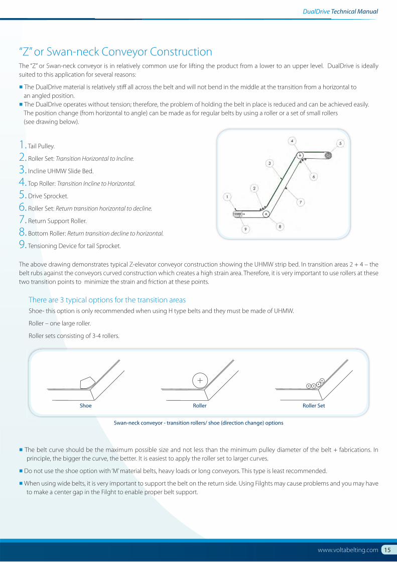
Swan-neck conveyor - transition rollers/ shoe (direction change) options
1. Tail Pulley.
2. Roller Set: Transition Horizontal to Incline.
3. Incline UHMW Slide Bed.
4. Top Roller: Transition Incline to Horizontal.
5. Drive Sprocket.
6. Roller Set: Return transition horizontal to decline.
7. Return Support Roller.
8. Bottom Roller: Return transition decline to horizontal.
9. Tensioning Device for tail Sprocket.
The above drawing demonstrates typical Z-elevator conveyor construction showing the UHMW strip bed. In transition areas 2 + 4 – the
belt rubs against the conveyors curved construction which creates a high strain area. Therefore, it is very important to use rollers at these
two transition points to minimize the strain and friction at these points.
“Z” or Swan-neck Conveyor ConstructionThe “Z” or Swan-neck conveyor is in relatively common use for lifting the product from a lower to an upper level. DualDrive is ideally
suited to this application for several reasons:
▪ The DualDrive material is relatively stiff all across the belt and will not bend in the middle at the transition from a horizontal to
an angled position.
▪ The DualDrive operates without tension; therefore, the problem of holding the belt in place is reduced and can be achieved easily.
The position change (from horizontal to angle) can be made as for regular belts by using a roller or a set of small rollers
(see drawing below).
There are 3 typical options for the transition areas
Shoe- this option is only recommended when using H type belts and they must be made of UHMW.
Roller – one large roller.
Roller sets consisting of 3-4 rollers.
▪ The belt curve should be the maximum possible size and not less than the minimum pulley diameter of the belt + fabrications. In
principle, the bigger the curve, the better. It is easiest to apply the roller set to larger curves.
▪ Do not use the shoe option with ‘M’ material belts, heavy loads or long conveyors. This type is least recommended.
▪ When using wide belts, it is very important to support the belt on the return side. Using Filghts may cause problems and you may have
to make a center gap in the Filght to enable proper belt support.

16 Volta Belting Technology Ltd.
DualDrive Teechnical Maanuuall
Conveyor Construction for quick dismounting
of the belt and telescoping supports to hold the belt
Tail Pulley
Tail Pulley
Smooth Back-bend PulleyDrive Sprocket
Conveyor Construcruction for quick dismounting
of the belt and teletelescoping supports to hold the be
Smooth Back-bend PulleyTail Pulley Tail Pulley
Drive Sprocket
Removing the Belt for CleaningThere are a number of options in the conveyor construction that allow the belt to be removed from the conveyor without being opened.
These common features are:
▪ Quick Release Tensioner - This device permits the release of belt tension without losing belt alignment (Page 13).
In some conveyors the telescoping supports are used. During normal operation of the conveyor, the supports are flush with the sides
of the conveyor. During cleaning or maintenance, the supports are pulled out and are in a position to hold the conveyor belt during
cleaning and maintenance (see drawing).
▪ The Hinge Lace or Metal Lace can be used to open the belt for cleaning and maintenance (Page 18).
Center Drive Conveyor
This conveyor is used in two typical applications: One option is where a larger centre drive pulley is employed and tail pulleys with smaller diameters (N.B. must be larger than the
recommended minimum pulley diameter) are required for the transfer of a product, One snub roller is sufficient; it should be positioned
tight against the belt running over the drive pulley.
In the upper drawing we can see centre drive application with two smooth back-bending pulleys. In this case, the belt must be tensioned
up to 0.5% to prevent slacking and jumping of the belt around the drive sprockets. In many cases the use of tight snub rollers can be seen,
as demonstrated in the lower drawing. These snub rollers are positioned tightly against both sides of the pulley to allow bi-directional
movement of the belt. In cases where the belt only runs in one direction, one snub roller is used.

17www.voltabelting.com
DualDrive Techniicaal MMaanuuaal
Flat Electrode Welding System
Flat Butt Welding System for Positive Drive Belts
5. Splicing the DualDriveThe DualDrive conveyor belt is manufactured with a series of teeth as
an integral part of the belt. These teeth are designed to mesh with the
teeth on the DualDrive drive sprockets. To ensure efficient performance,
it is necessary to maintain the spacing between the teeth in the region
of the weld. We recommend using Volta Tools for this procedure. These
tools are designed for use with all of our belts and materials. They are
also designed to maintain the correct spacing between the teeth on the
DualDrive belt.
FT - Electrode Welding KitThe FT-1000 and FT-1500 are designed to provide
electrode welding capability for all our Flat belts,
including the DualDrive belt. These kits use a trimmer
to prepare the belt ends for welding and also for cleaning
the joint after welding.
The FT-1000 is capable of welding belts up to 1000 mm (40”) wide with
a 90˚ weld.
The FT-1500 can weld belts up to 1500 mm (60”) wide with a 90˚ weld.
FBW Flat Butt Welding ToolThe FBW tool is used to butt weld flat belts making them endless. The
process eliminates the use of electrodes making the welding process
faster and cleaner.
FBW common model sizes:FBW-301, FBW-721, FBW-1061 and FBW-1301.

18 Volta Belting Technology Ltd.
DualDrive Teechnical Maanuuall
The Volta Lace is a connector that allows you to easily open the belt by taking the pin out, clean or service the conveyor, reinstall the belt
and close the lace with a new pin. Volta belts are renowned for their hygienic and homogeneous characteristics, therefore, they do not
require opening and closing on a regular basis- unlike modular belts.
We recommend using lace only when absolutely necessary.
Volta Lace is made of homogeneous food approved materials and is compatible with the Volta ‘M’ family product belts of 2.5 to 5mm
thickness. The thermo-welded join of the lace to the base belt is tough and will not tear apart. Volta lace can also be used in applications
where metal detectors are required and we can provide you with a polyester pin upon request.
Volta DualDrive LaceWhen using DualDrive Lace, make sure that there are pulleys every 4” (100mm) between the
centers of both the conveyor drive and tail shafts. Make sure that the pull force on the belt is
less than the allowed pull force of the lace.
DualDrive Lace Specifications
Product Volta LMW 16 DD Volta LMB 16 DD
Description Flat toothed strip Flat toothed strip
Material Volta MW, Beige Volta MB, Blue
FDA /USDA /USDA Dairy Approval
/ EU Approved
FDA /USDA /USDA Dairy Approval
/ EU Approved
Hardness 53D 53D
Working Temp Range-20°C to 60°C -20°C to 60°C
-5°F to 140°F -5°F to 140°F
Max Pull Force 3.8 kg/cm, 21.3 lb/inch 3.8 kg/cm, 21.3 lb/inch
When using DD Lace, make sure that the pull force applied on the belt does not exceed the maximum pull force allowed for the lace.
Minimum Sprocket Diameter 100 mm ( 4” )
Dimensions
Length 1.2m/ 3.93ft 1.2m/ 3.93ft
Lace Pin
Stainless steel 1.6 - 1.8 mm (0.065”)
Nylon steel pin 1.65 mm (0.065”)
(Nylon-coated steel pin )
6. Volta Fasteners

19www.voltabelting.com
DualDrive Techniicaal MMaanuuaal
Closing belt with Universal Lace
A
B
Detail A
Detail B
Volta Universal LaceThe standard Universal Lace is another option that can be used to fasten DualDrive belts.
We recommend using the Universal Lace only when absolutely necessary.
Make sure that the conveyor pulleys fully support the entire face length of the belt or at least 80%
of the face length. Note that the maximum allowed pull force for the lace (per cm/inch.) is lower
than the allowed pull force of the belt (per cm/inch). Therefore, check that the calculated pull force
of your belt is lower than the maximum allowed pull force of the lace.
The fastening structure allows you to easily open the
belt by removing the pin and to reinstall the belt by
simply inserting a new pin to close the belt again.
Universal Lace Specifications
Volta LMW-U Volta LMB-U
Description Flat toothed strip Flat toothed strip
Material Volta MW, beige Volta MB, blue
Hardness 95A 95A
Working Temp Range -20°C to 60°C/ -5°F to 140°F -20°C to 60°C/ -5°F to 140°F
Dimensions 5 x 16 mm - 0.2 in x 0.63 in 5 x 16 mm - 0.2 in x 0.63 in
Max Length 3.05 m - 10 ft 3.05 m - 10 ft
Max Pull Force 3 kg/cm - 16.8 lb/in 3 kg/cm - 16.8 lb/in
Minimum PulleyNormal Flex with DD 3mm
80 mm/ 31/8 in. 80 mm/ 31/8 in.
Minimum PulleyBack Flex with DD 3mm
100 mm/ 4 in. 100 mm/ 4 in.
Hinge Pin Stainless Steel: 1.2 - 1.4 mm, Polyester: 1.2 mm diameter / FDA approved
When using lace fasteners, ensure that you keep uniform pitch between teeth so that your conveyor performs well.

20 Volta Belting Technology Ltd.
DualDrive Teechnical Maanuuall
F = fS * ( G1+G2 ) + fR * G2 * + fR * G3 + C * G1 * + 0.25 * G4XL
H
LXL
7. Belt Calculations
Pull Force Calculation Procedure1. Net Pull Force F on the belt is calculated by the formula
Symbols and DimensionsfR = Coefficient of friction of rollers (Bearings or Bushing)
fS = Coefficient of friction of belt on slidebed
L = Conveyor length (m)/ (ft)
H = Elevating height (m)/ (ft)
X = Horizontal distance of conveyor (m)/ (ft)
G1 = Maximum load on the conveyor (kg)/ (Lb)
G2 = Belt weight (one direction) (kg)/ (Lb)
G3 = Weight of supporting rolls-upper and lower section (kg)/(Lb)
G4 = Maximum accumulated weight (kg)/ (Lb)
* In case of Z Conveyor the calculation is made up of two conveyors, one horizontal and one inclined. In order to find the total Pull Force,
add the results of both calculations.
Conveyor with slide bed
Return BedRollers with Bearings
fR = 0.03
Rollers with Bushing
fR = 0.1
UHMW Sliders
fR = refer to technical data sheet
Slide Bed fs = refer to technical data sheet, pgs. 4, 6 and 8
1. Horizontal transport C = 0; L = X; H = 0
2. Incline C = 1
3. Decline C = -1

21www.voltabelting.com
DualDrive Techniicaal MMaanuuaal
2. Calculate the allowed pull force (Fa) according to number of teeth in meshIf the number of teeth in mesh is five or less, an adjustment must be made to the max pull force.
Multiply the max pull force by K factor.
Teeth in Mesh K factor Comment
6 or more 1 ( 180° Arc of contact at standard 150 mm/6” pulley)
5 0.8
4 0.6 ( 180° Arc of contact at standard 100 mm/4” pulley)
Table 5: K factor
Fa = F * K
Fa = Allowed Pull Force
3. Choose the belt widthDivide the calculated pull force by the belt width to get the pull force per unit width.
Check that the calculated pull force per unit width is less than the maximum.
Allow Pull Force according to number of teeth in mesh for the belt (Fa).
When using DualDrive Lace, make sure that the Pull force on the belt is less than the allowed Pull force of the Lace.
Example:
An UHMW slide bed conveyor transporting meat packages horizontally.
1. Check if 18” belt (457 mm) is good for this application.
Given English-Imperial Metric
Package weight: 30 (lbs) 13.6 (kg)
Maximum number of packages on belt: 30 30
Conveyor length: 50 (ft) 15.2 (m)
Return rollers weight (bushing): 10 (lbs) 4.5 (kg)
Number of return idlers: 6 6
Pulley diameter: 152 mm 6”
Number of teeth in mesh: 6 6
Procedure
Calculate the Pull Force:
Maximum load: G1= 30 * 30 = 900 (lbs) G1= 30 * 13.6 = 408 (kg)
Belt weight - one direction: G2=0.85*(18/12)* 50 = 63.75 lbs G2= 4.15*0.457*15.2= 28.82 kg
Return idler weight: G3= 6*10 =60 (lbs) G3 = 6*4.5 = 27 (kg)
Accumulated weight : G4=0 G4=0
F= fs*(G1+G2)+ fr*(G2+G3)+0.25*G4
F=0.28*(900+63.7)+0.1*(63.7+60)
F= 282.2 (lbs)
F=0.28*(408+28.8)+0.1*(28.8+27)
F=127.9 (kg)
2. Allow Pull Force according to number of teeth in mesh :
For 10 teeth sprockets at 180° Arc of contact - 5 teeth in mesh
K =0.8 (5 teeth in mesh)
3. Maximum allowed belt load: Fa =0.8* 33.6 = 26.8 (lb/in) Fa = 0.8* 6 =4.8 (kg/cm)
F(max) =26.8 * 18 = 482.4 (lbs) F(max) =4.8*45= 216 (kg)
4. Belt width: 18” belt width (45 cm) is ok
(the calculated Pull Force is less than the allowed Pull Force)

22 Volta Belting Technology Ltd.
DualDrive Teechnical Maanuuall
Calculation Procedure (for constant speed) 1. Calculation of the required torque for the drive pulley
8. Motor Capacity Calculation:
Metric English
F* 9.81*Dp
1000 * 2M =
F* Dp
12 * 2M =
M = torque [N * m] M = torque [lb. * ft.]
F = calculated pull force [kg] - see section 6.1, pg. 24 F = calculated pull force [lb.] - see section 6.1, pg. 24
Dp = pulley pitch diameter [mm] - see page 10 Dp = pulley pitch diameter [in.] - see page 10
2. Calculation of drive pulley revolution [rpm]
V*1000
π*Dpn =
V*12
π*Dpn =
n = number of drive pulley revolution [rpm] n = number of drive pulley revolution [rpm]
Dp = pulley pitch diameter [mm] - see page 10 Dp = pulley pitch diameter [in.] - see page10
V = belt speed [m/min] V = belt speed [ft./min]
3. Calculation of the motor capacity
M*n
9550*ηP = *k
M*n
5250*ηP = *k
P = power in [Kw] (0.746 Kw = 1 HP) P = power in [HP] (1 HP = 0.746 Kw)
M = torque [N . m] (from step 1) M = torque [lb. . ft.] (from step 1)
n = number of drive pulley revolution [rpm] (from step 2) n = number of drive pulley revolution [rpm] (from step 2)
η = efficiency of the drive transmission equipment (η < 1) η = efficiency of the drive transmission equipment (η < 1)
It depends on the drive type and motor data provided by the manufacturer. In most cases it may vary from 0.6 to 0.85.
k = correction/ safety coefficient (K > 1) k = correction/ safety coefficient (K > 1)
Take into account working conditions according to the motor and drive gear data provided by the manufacturer.
4. Choose a motor: the next size up

23www.voltabelting.com
DualDrive Techniicaal MMaanuuaal
Idler RollersReturn Side Support
DualDrive with Flights Return Side Support
Volta Drive Sprocket Modular Drive Sprocket
9. Applications

www.voltabelting.com
Corporate Headquarters
Sales and Manufacturing
USA
Tel: +1 973 276 7905
Fax: +1 973 276 7908
Toll Free: 1-877-VOLTAUS
EUROPE
Tel: +31-546-580166
Fax: +31-546-579508
Volta Belting makes no warranty with respect to any of its products for a particular purpose. See Volta General Terms and Conditions.
Copyright©2012 Volta Belting Technology Ltd. CAT204EN00 - Ver. A - February 2012
The DualDrive Solution
▪ Versatile belt combines high hygienic standards with positive-drive benefits.
▪ Extremely smooth surface prevents the accumulation of bacteria.
▪ Positive-drive feature does not require tensioning of the belt.
▪ Simple heat welded joins and fabrications.
▪ Huge savings in water and cleaning downtime.
▪ FDA/USDA AMS Equipment Acceptance Certificate in compliance with NSF/ANSI/3A 14159-3 – 2005 for Meat
and Poultry Processing
▪ USDA Dairy Equipment for selected products.
▪ Declaration of conformity in compliance with EU Regulations no. : 10/2011, 1935/2004 and Directive
2002/72 EC
▪ Supports the HACCP concept.