S-Wall™ Sidewall Conveyor Belting · S-Wall™ Sidewall Conveyor Belting Technical Manual The...
44
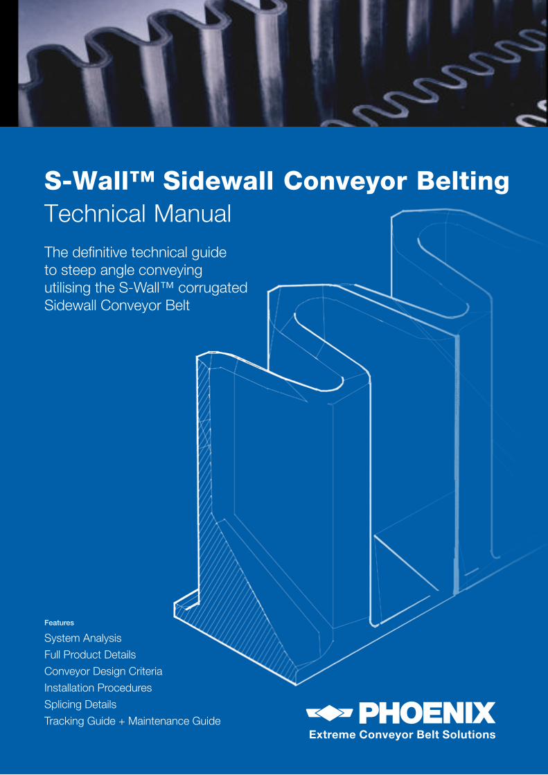
S-Wall™ Sidewall Conveyor Belting Technical Manual The definitive technical guide to steep angle conveying utilising the S-Wall™ corrugated Sidewall Conveyor Belt Extreme Conveyor Belt Solutions Features System Analysis Full Product Details Conveyor Design Criteria Installation Procedures Splicing Details Tracking Guide + Maintenance Guide
-
Upload
nguyenlien -
Category
Documents
-
view
231 -
download
7
Transcript of S-Wall™ Sidewall Conveyor Belting · S-Wall™ Sidewall Conveyor Belting Technical Manual The...
S-Wall™ Sidewall Conveyor BeltingTechnical ManualThe definitive technical guide to steep angle conveying utilising the S-Wall™ corrugated Sidewall Conveyor Belt
Extreme Conveyor Belt Solutions
Extreme Conveyor Belt Solutions
Features
System Analysis
Full Product Details
Conveyor Design Criteria
Installation Procedures
Splicing Details
Tracking Guide + Maintenance Guide
2 PHOENIX Conveyor Belts
S-WALL™
Extreme Conveyor Belt Solutions
Extreme Conveyor Belt Solutions
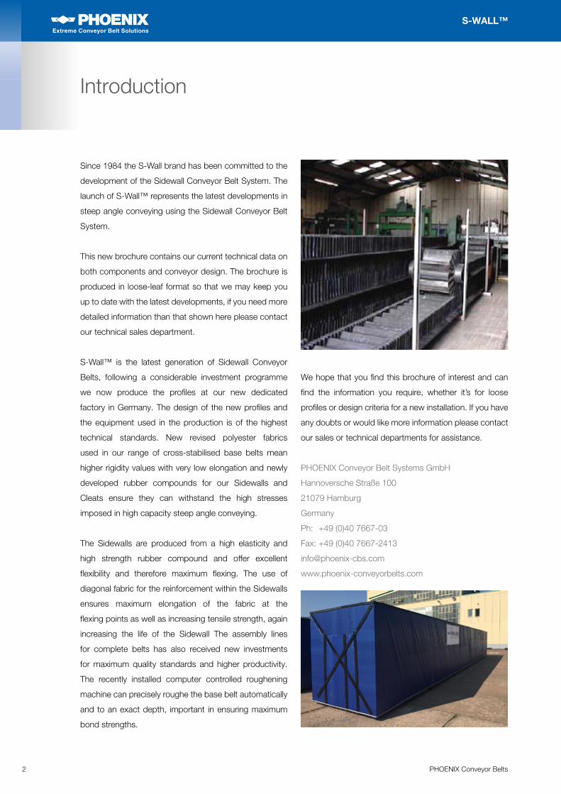
Since 1984 the S-Wall brand has been committed to the
development of the Sidewall Conveyor Belt System. The
launch of S-Wall™ represents the latest developments in
steep angle conveying using the Sidewall Conveyor Belt
System.
This new brochure contains our current technical data on
both components and conveyor design. The brochure is
produced in loose-leaf format so that we may keep you
up to date with the latest developments, if you need more
detailed information than that shown here please contact
our technical sales department.
S-Wall™ is the latest generation of Sidewall Conveyor
Belts, following a considerable investment programme
we now produce the profiles at our new dedicated
factory in Germany. The design of the new profiles and
the equipment used in the production is of the highest
technical standards. New revised polyester fabrics
used in our range of cross-stabilised base belts mean
higher rigidity values with very low elongation and newly
developed rubber compounds for our Sidewalls and
Cleats ensure they can withstand the high stresses
imposed in high capacity steep angle conveying.
The Sidewalls are produced from a high elasticity and
high strength rubber compound and offer excellent
flexibility and therefore maximum flexing. The use of
diagonal fabric for the reinforcement within the Sidewalls
ensures maximum elongation of the fabric at the
flexing points as well as increasing tensile strength, again
increasing the life of the Sidewall The assembly lines
for complete belts has also received new investments
for maximum quality standards and higher productivity.
The recently installed computer controlled roughening
machine can precisely roughe the base belt automatically
and to an exact depth, important in ensuring maximum
bond strengths.
We hope that you find this brochure of interest and can
find the information you require, whether it’s for loose
profiles or design criteria for a new installation. If you have
any doubts or would like more information please contact
our sales or technical departments for assistance.
PHOENIX Conveyor Belt Systems GmbH
Hannoversche Straße 100
21079 Hamburg
Germany
Ph: +49 (0)40 7667-03
Fax: +49 (0)40 7667-2413
www.phoenix-conveyorbelts.com
Introduction
3PHOENIX Conveyor Belts
S-WALL™
Extreme Conveyor Belt Solutions
Extreme Conveyor Belt Solutions
System Advantages
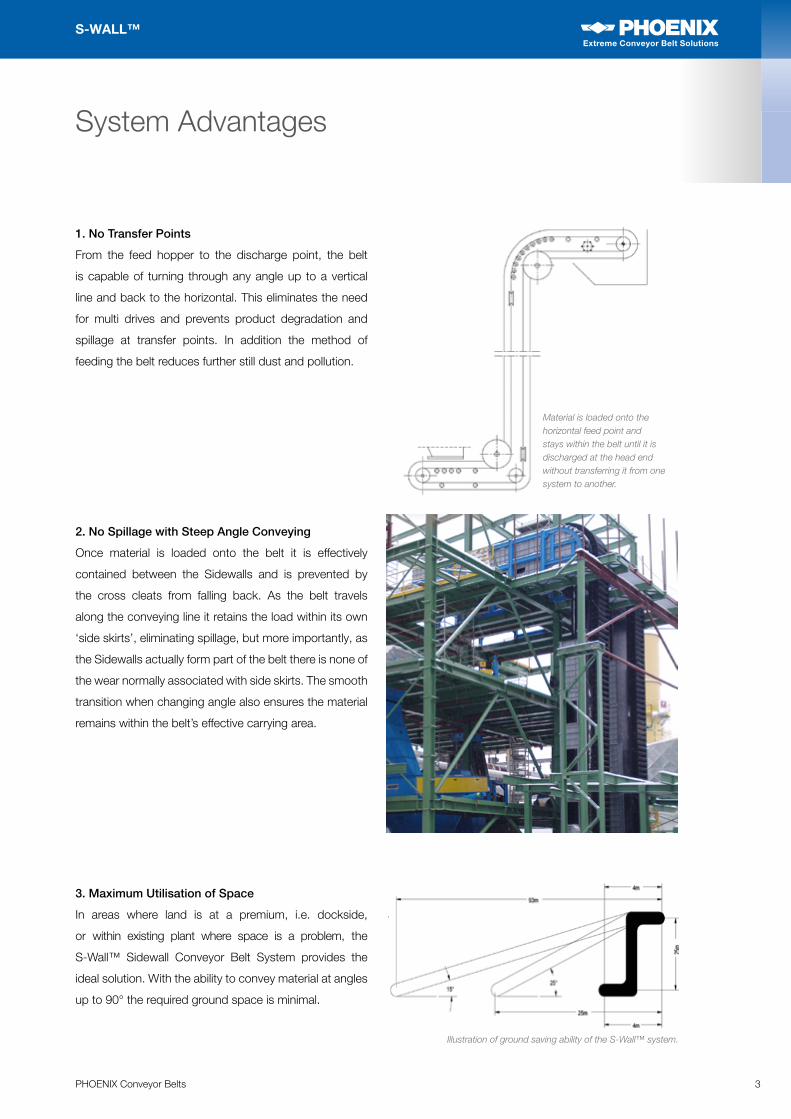
1. No Transfer Points
From the feed hopper to the discharge point, the belt
is capable of turning through any angle up to a vertical
line and back to the horizontal. This eliminates the need
for multi drives and prevents product degradation and
spillage at transfer points. In addition the method of
feeding the belt reduces further still dust and pollution.
2. No Spillage with Steep Angle Conveying
Once material is loaded onto the belt it is effectively
contained between the Sidewalls and is prevented by
the cross cleats from falling back. As the belt travels
along the conveying line it retains the load within its own
‘side skirts’, eliminating spillage, but more importantly, as
the Sidewalls actually form part of the belt there is none of
the wear normally associated with side skirts. The smooth
transition when changing angle also ensures the material
remains within the belt’s effective carrying area.
3. Maximum Utilisation of Space
In areas where land is at a premium, i.e. dockside,
or within existing plant where space is a problem, the
S-Wall™ Sidewall Conveyor Belt System provides the
ideal solution. With the ability to convey material at angles
up to 90° the required ground space is minimal.
Material is loaded onto the horizontal feed point and stays within the belt until it is discharged at the head end without transferring it from one system to another.
Illustration of ground saving ability of the S-Wall™ system.
4 PHOENIX Conveyor Belts
S-WALL™
Extreme Conveyor Belt Solutions
Extreme Conveyor Belt Solutions
System Advantages
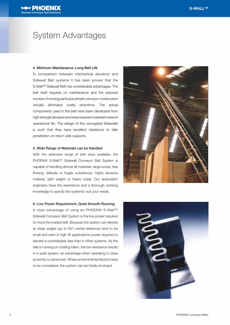
4. Minimum Maintenance, Long Belt Life
In comparison between mechanical elevators and
Sidewall Belt systems it has been proven that the
S-Wall™ Sidewall Belt has considerable advantages. The
belt itself requires no maintenance and the reduced
number of moving parts plus simple conveyor construction
virtually eliminates costly downtime. The actual
components used in the belt have been developed from
high strength abrasion and wear resistant material to extend
operational life. The design of the corrugated Sidewalls
is such that they have excellent resistance to idler
penetration on return side supports.
5. Wide Range of Materials can be Handled
With the extensive range of belt sizes available, the
PHOENIX S-Wall™ Sidewall Conveyor Belt System is
capable of handling almost all materials: large lumps, free
flowing, delicate or fragile substances, highly abrasive
material, light weight or heavy loads. Our application
engineers have the experience and a thorough working
knowledge to specify the systemto suit your needs.
6. Low Power Requirement, Quiet Smooth Running
A clear advantage of using an PHOENIX S-Wall™
Sidewall Conveyor Belt System is the low power required
to move the loaded belt. Because the system can elevate
at steep angles (up to 90°) centre distances tend to be
small and even in high lift applications power required to
elevate is considerably less than in other systems. As the
belt is running on rotating idlers, the low resistance results
in a quiet system, an advantage when operating in close
proximity to personnel. Where environmental factors need
to be considered, the system can be totally enclosed.

5PHOENIX Conveyor Belts
S-WALL™
Extreme Conveyor Belt Solutions
Extreme Conveyor Belt Solutions
The next section gives details of the S-Wall™ range of profiles.
Profiles
Sidewalls 6
Cleats 8
Cross-Stabilised Base Belts 11
6 PHOENIX Conveyor Belts
S-WALL™
Extreme Conveyor Belt Solutions
Extreme Conveyor Belt Solutions
Sidewalls
S-Wall™ Sidewalls are available in 4 basic product
groups as shown below. If purchased as loose profiles the
Sidewalls are packed into non-returnable containers,
there is not normally any minimum order quantity, however
for special qualities please check before ordering. Please
refer to your price list for information on ordering and
quantity discounts.
PHOENIX S-Wall™ corrugated Sidewalls represent the
latest in design ideas and manufacturing techniques.
The Sidewall design ensures maximum flexing without
fatigue, the profile has excellent vertical stability for load
retention and return side support. The design allows
for high compression to ensure smooth inner deflection
around small radii. Another important design feature is
that the Sidewalls can be pressed from both sides when
mounting, this offers much higher bond strengths and
security.
The fabric insertion is of the diagonal type which gives
excellent tear resistance and also allows the Sidewall to
flex more easily.
The rubber compounds used have been tested to ensure
maximum flexibility along with high abrasion resistant and
high tensile strength.
The ‘in-house’ test conveyor designed and built
specifically to test the new range of S-Wall™ Sidewalls
has proved the design and rubber compounds work
together in harmony increasing the life of the Sidewall and
ensuring maximum durability.
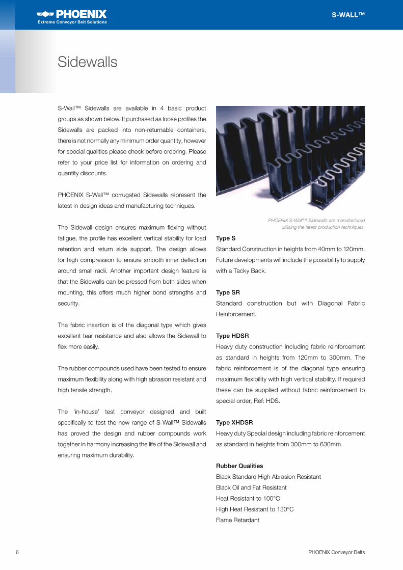
PHOENIX S-Wall™ Sidewalls are manufactured utilising the latest production techniques.
Type S
Standard Construction in heights from 40mm to 120mm.
Future developments will include the possibility to supply
with a Tacky Back.
Type SR
Standard construction but with Diagonal Fabric
Reinforcement.
Type HDSR
Heavy duty construction including fabric reinforcement
as standard in heights from 120mm to 300mm. The
fabric reinforcement is of the diagonal type ensuring
maximum flexibility with high vertical stability. If required
these can be supplied without fabric reinforcement to
special order, Ref: HDS.
Type XHDSR
Heavy duty Special design including fabric reinforcement
as standard in heights from 300mm to 630mm.
Rubber Qualities
Black Standard High Abrasion Resistant
Black Oil and Fat Resistant
Heat Resistant to 100°C
High Heat Resistant to 130°C
Flame Retardant
7PHOENIX Conveyor Belts
S-WALL™
Extreme Conveyor Belt Solutions
Extreme Conveyor Belt Solutions
Sidewalls
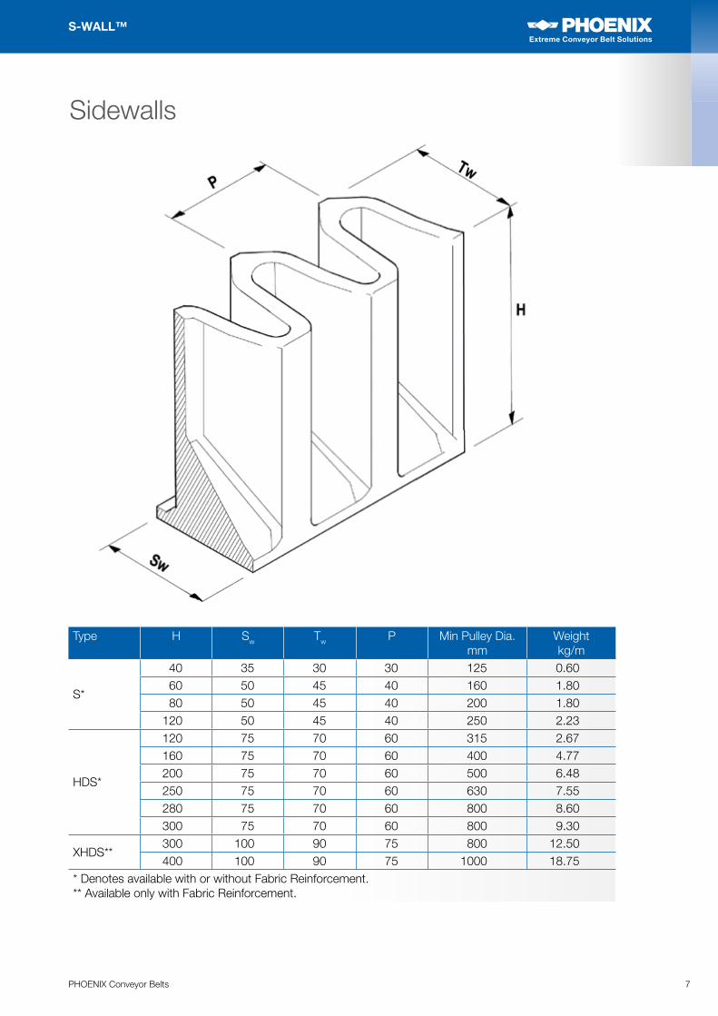
Type H Sw Tw P Min Pulley Dia. mm
Weightkg/m
S*
40 35 30 30 125 0.6060 50 45 40 160 1.8080 50 45 40 200 1.80
120 50 45 40 250 2.23
HDS*
120 75 70 60 315 2.67160 75 70 60 400 4.77200 75 70 60 500 6.48250 75 70 60 630 7.55280 75 70 60 800 8.60300 75 70 60 800 9.30
XHDS**300 100 90 75 800 12.50400 100 90 75 1000 18.75
* Denotes available with or without Fabric Reinforcement.** Available only with Fabric Reinforcement.
8 PHOENIX Conveyor Belts
S-WALL™
Extreme Conveyor Belt Solutions
Extreme Conveyor Belt Solutions
Cleats
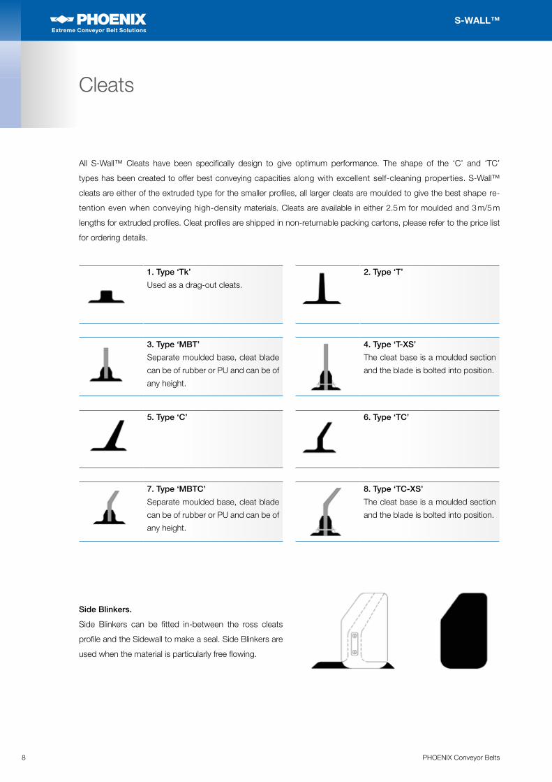
All S-Wall™ Cleats have been specifically design to give optimum performance. The shape of the ‘C’ and ‘TC’
types has been created to offer best conveying capacities along with excellent self-cleaning properties. S-Wall™
cleats are either of the extruded type for the smaller profiles, all larger cleats are moulded to give the best shape re-
tention even when conveying high-density materials. Cleats are available in either 2.5 m for moulded and 3 m/5 m
lengths for extruded profiles. Cleat profiles are shipped in non-returnable packing cartons, please refer to the price list
for ordering details.
1. Type ‘Tk’
Used as a drag-out cleats.
3. Type ‘MBT’
Separate moulded base, cleat blade
can be of rubber or PU and can be of
any height.
5. Type ‘C’
7. Type ‘MBTC’
Separate moulded base, cleat blade
can be of rubber or PU and can be of
any height.
2. Type ‘T’
4. Type ‘T-XS’
The cleat base is a moulded section
and the blade is bolted into position.
6. Type ‘TC’
8. Type ‘TC-XS’
The cleat base is a moulded section
and the blade is bolted into position.
Side Blinkers.
Side Blinkers can be fitted in-between the ross cleats
profile and the Sidewall to make a seal. Side Blinkers are
used when the material is particularly free flowing.
9PHOENIX Conveyor Belts
S-WALL™
Extreme Conveyor Belt Solutions
Extreme Conveyor Belt Solutions
Cleats
Ancillary Equipment for S-Wall™ Cleat Profiles
Screw Reinforcement sets are available in a selection of sizes to suit specific Cleat designs as follows:
• Type 1 Cleat height 75 mm
• Type 2 Cleat heights 90 mm to 110 mm
• Type 3 Cleat height 110 mm
• Type 4 Cleat heights 140 mm to 180 mm
• Type 5 Cleat heights 180 mm to 230 mm
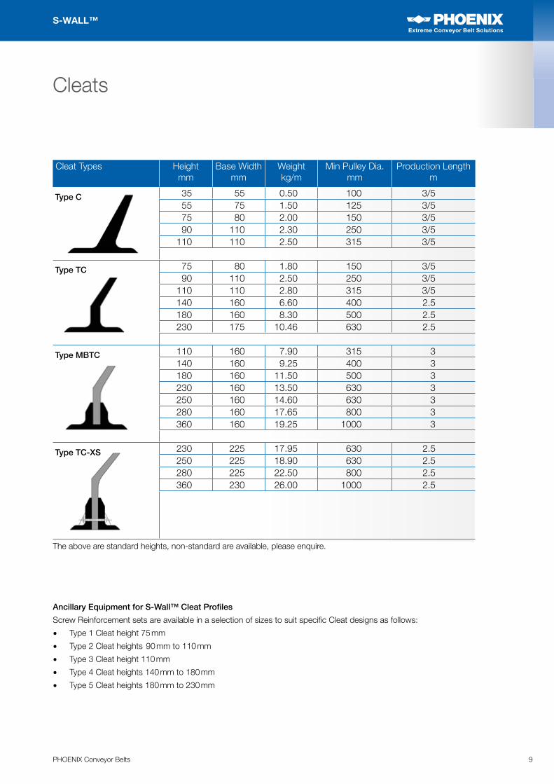
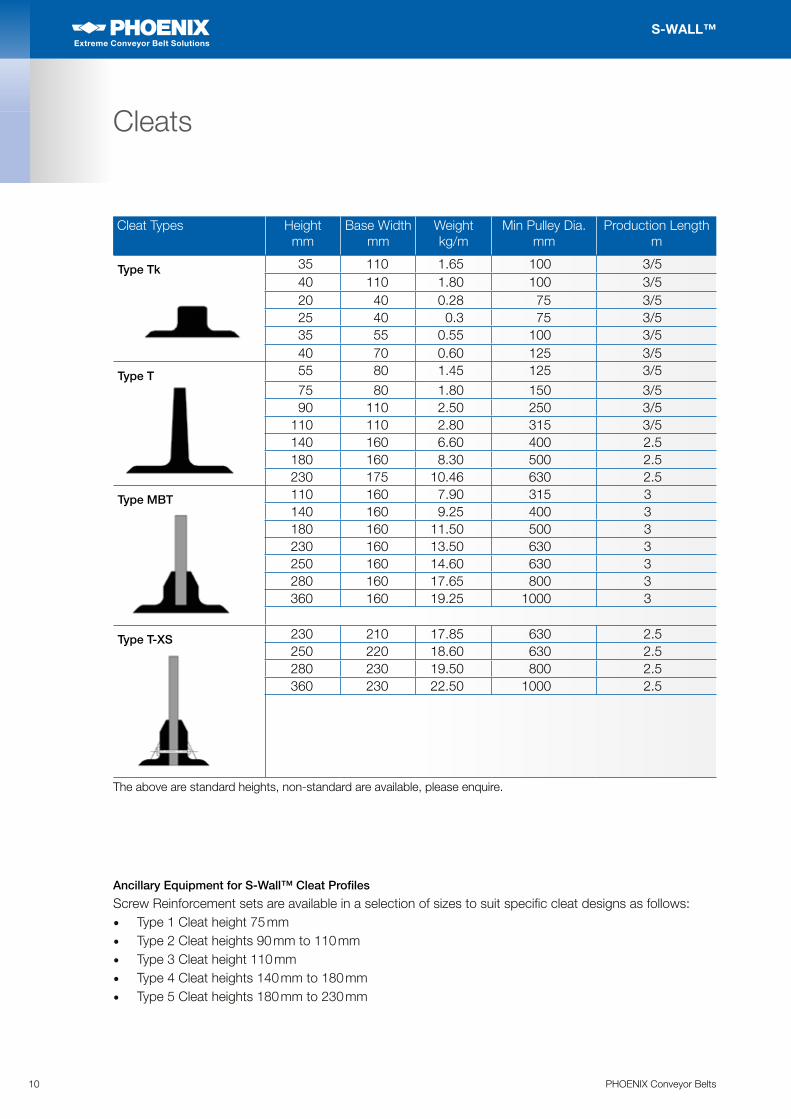
Cleat Types Height mm
Base Width mm
Weight kg/m
Min Pulley Dia. mm
Production Length m
35 55 0.50 100 3/555 75 1.50 125 3/575 80 2.00 150 3/590 110 2.30 250 3/5
110 110 2.50 315 3/5
75 80 1.80 150 3/590 110 2.50 250 3/5
110 110 2.80 315 3/5140 160 6.60 400 2.5180 160 8.30 500 2.5230 175 10.46 630 2.5
110 160 7.90 315 3140 160 9.25 400 3180 160 11.50 500 3230 160 13.50 630 3250 160 14.60 630 3280 160 17.65 800 3360 160 19.25 1000 3
230 225 17.95 630 2.5250 225 18.90 630 2.5280 225 22.50 800 2.5360 230 26.00 1000 2.5
The above are standard heights, non-standard are available, please enquire.
Type C
Type TC
Type MBTC
Type TC-XS
10 PHOENIX Conveyor Belts
S-WALL™
Extreme Conveyor Belt Solutions
Extreme Conveyor Belt Solutions
Cleats
Cleat Types Height mm
Base Width mm
Weightkg/m
Min Pulley Dia. mm
Production Length m
35 110 1.65 100 3/540 110 1.80 100 3/520 40 0.28 75 3/525 40 0.3 75 3/535 55 0.55 100 3/540 70 0.60 125 3/555 80 1.45 125 3/5
75 80 1.80 150 3/590 110 2.50 250 3/5
110 110 2.80 315 3/5140 160 6.60 400 2.5180 160 8.30 500 2.5230 175 10.46 630 2.5110 160 7.90 315 3140 160 9.25 400 3180 160 11.50 500 3230 160 13.50 630 3250 160 14.60 630 3280 160 17.65 800 3360 160 19.25 1000 3
230 210 17.85 630 2.5250 220 18.60 630 2.5280 230 19.50 800 2.5360 230 22.50 1000 2.5
Type Tk
Type T
Type MBT
Type T-XS
Ancillary Equipment for S-Wall™ Cleat Profiles
Screw Reinforcement sets are available in a selection of sizes to suit specific cleat designs as follows:• Type 1 Cleat height 75 mm• Type 2 Cleat heights 90 mm to 110 mm• Type 3 Cleat height 110 mm• Type 4 Cleat heights 140 mm to 180 mm• Type 5 Cleat heights 180 mm to 230 mm
The above are standard heights, non-standard are available, please enquire.
11PHOENIX Conveyor Belts
S-WALL™
Extreme Conveyor Belt Solutions
Extreme Conveyor Belt Solutions
Base Belts
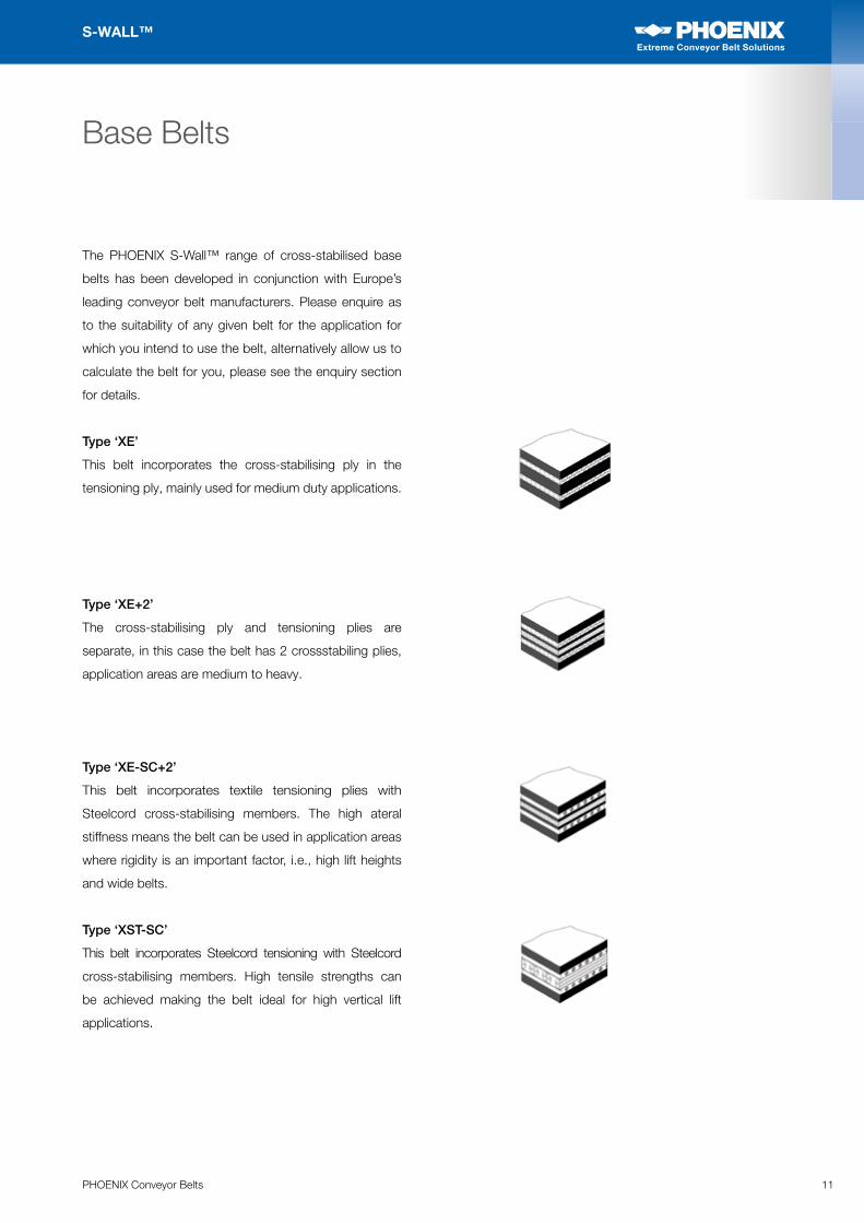
The PHOENIX S-Wall™ range of cross-stabilised base
belts has been developed in conjunction with Europe’s
leading conveyor belt manufacturers. Please enquire as
to the suitability of any given belt for the application for
which you intend to use the belt, alternatively allow us to
calculate the belt for you, please see the enquiry section
for details.
Type ‘XE’
This belt incorporates the cross-stabilising ply in the
tensioning ply, mainly used for medium duty applications.
Type ‘XE+2’
The cross-stabilising ply and tensioning plies are
separate, in this case the belt has 2 crossstabiling plies,
application areas are medium to heavy.
Type ‘XE-SC+2’
This belt incorporates textile tensioning plies with
Steelcord cross-stabilising members. The high ateral
stiffness means the belt can be used in application areas
where rigidity is an important factor, i.e., high lift heights
and wide belts.
Type ‘XST-SC’
This belt incorporates Steelcord tensioning with Steelcord
cross-stabilising members. High tensile strengths can
be achieved making the belt ideal for high vertical lift
applications.
12 PHOENIX Conveyor Belts
S-WALL™
Extreme Conveyor Belt Solutions
Extreme Conveyor Belt Solutions
Base Belts
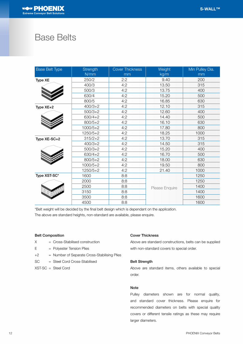
Base Belt Type Strength N/mm
Cover Thickness mm
Weightkg/m
Min Pulley Dia. mm
250/2 2:2 9.40 200400/3 4:2 13.50 315500/3 4:2 13.75 400630/4 4:2 15.20 500800/5 4:2 16.85 630400/3+2 4:2 12.10 315500/3+2 4:2 12.60 400630/4+2 4:2 14.40 500800/5+2 4:2 16.10 630
1000/5+2 4:2 17.80 8001250/5+2 4:2 18.25 1000315/2+2 4:2 13.70 315400/3+2 4:2 14.50 315500/3+2 4:2 15.20 400630/4+2 4:2 16.70 500800/5+2 4:2 18.00 630
1000/5+2 4:2 19.50 8001250/5+2 4:2 21.40 10001600 8:8 12502000 8:8 12502500 8:8 14003150 8:8 14003500 8:8 16004500 8:8 1600
Please Enquire
Type XE
Type XE+2
Type XE-SC+2
Type XST-SC*
*Belt weight will be decided by the final belt design which is dependant on the application.
The above are standard heights, non-standard are available, please enquire.
Belt Composition
X = Cross-Stabilised construction
E = Polyester Tension Plies
+2 = Number of Separate Cross-Stabilising Plies
SC = Steel Cord Cross-Stabilised
XST-SC = Steel Cord
Cover Thickness
Above are standard constructions, belts can be supplied
with non-standard covers to special order.
Belt Strength
Above are standard items, others available to special
order.
Note
Pulley diameters shown are for normal quality,
and standard cover thickness. Please enquire for
recommended diameters on belts with special quality
covers or different tensile ratings as these may require
larger diameters.
13PHOENIX Conveyor Belts
S-WALL™
Extreme Conveyor Belt Solutions
Extreme Conveyor Belt Solutions
The next section gives details on the basics of correct conveyor design for S-Wall™ steep inclineconveyors.
Customers are strongly recommended to check with our technical department if unsureabout any aspect of belt
selection or conveyor design.
Carrying Side Support 14
Return Side Support 15
Belt Feeding and Feed Hopper Design 16
Upturn Deflection 17
Top Inner Deflection 19
Drive and Tail Pulley 20
Pulley Crowning 21
Snubbing 22
Downturn Deflection 23
Bottom Inner Deflection 24
Belt Cleaning 25
Guiding Wheels 27
Belt Tracking 29
Ancilliary Equipment 30
Design Information
14 PHOENIX Conveyor Belts
S-WALL™
Extreme Conveyor Belt Solutions
Extreme Conveyor Belt Solutions
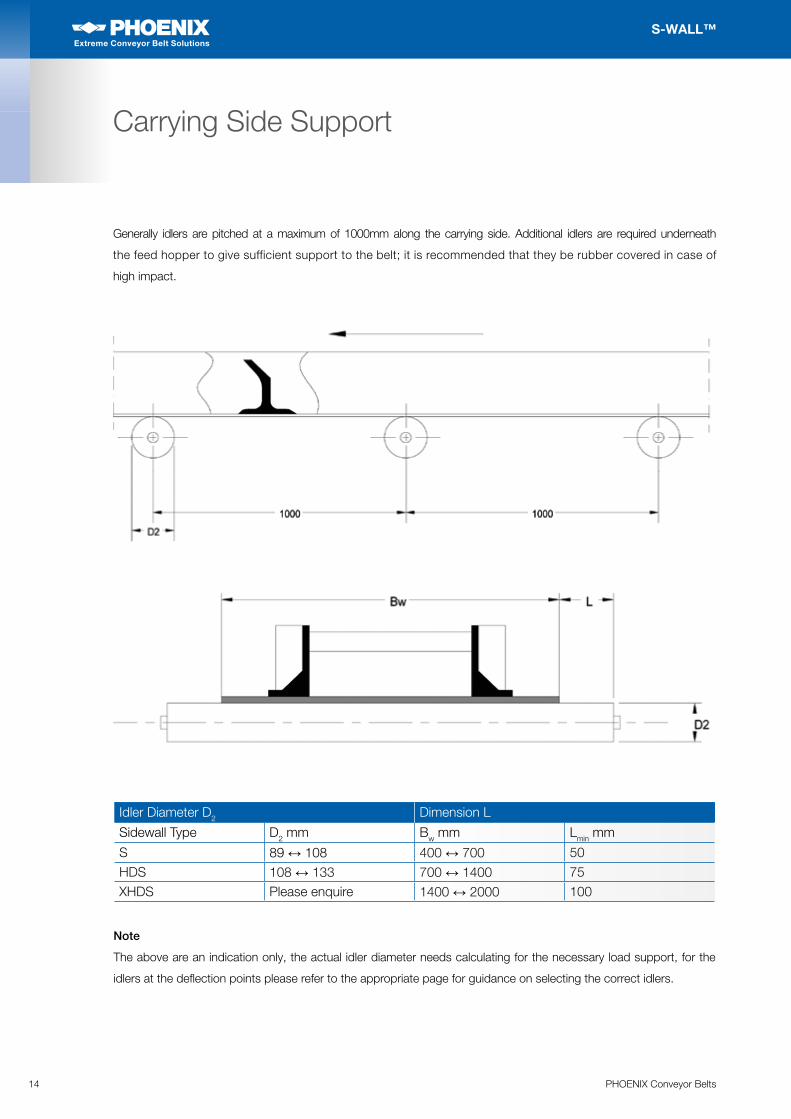
Carrying Side Support
Generally idlers are pitched at a maximum of 1000mm along the carrying side. Additional idlers are required underneath
the feed hopper to give sufficient support to the belt; it is recommended that they be rubber covered in case of
high impact.
Idler Diameter D2 Dimension L
Sidewall Type D2 mm Bw mm Lmin mm
S 89 ↔ 108 400 ↔ 700 50HDS 108 ↔ 133 700 ↔ 1400 75XHDS Please enquire 1400 ↔ 2000 100
Note
The above are an indication only, the actual idler diameter needs calculating for the necessary load support, for the
idlers at the deflection points please refer to the appropriate page for guidance on selecting the correct idlers.
15PHOENIX Conveyor Belts
S-WALL™
Extreme Conveyor Belt Solutions
Extreme Conveyor Belt Solutions
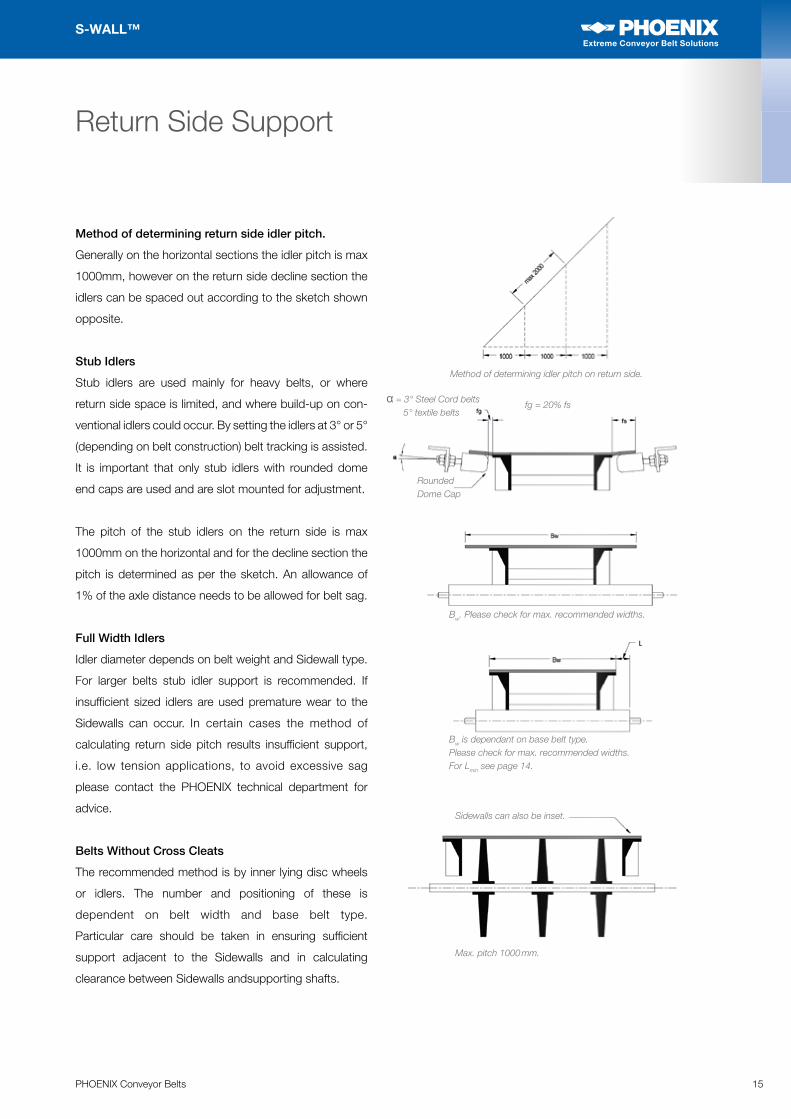
Return Side Support
Method of determining return side idler pitch.
Generally on the horizontal sections the idler pitch is max
1000mm, however on the return side decline section the
idlers can be spaced out according to the sketch shown
opposite.
Stub Idlers
Stub idlers are used mainly for heavy belts, or where
return side space is limited, and where build-up on con-
ventional idlers could occur. By setting the idlers at 3° or 5°
(depending on belt construction) belt tracking is assisted.
It is important that only stub idlers with rounded dome
end caps are used and are slot mounted for adjustment.
The pitch of the stub idlers on the return side is max
1000mm on the horizontal and for the decline section the
pitch is determined as per the sketch. An allowance of
1% of the axle distance needs to be allowed for belt sag.
Full Width Idlers
Idler diameter depends on belt weight and Sidewall type.
For larger belts stub idler support is recommended. If
insufficient sized idlers are used premature wear to the
Sidewalls can occur. In certain cases the method of
calculating return side pitch results insufficient support,
i.e. low tension applications, to avoid excessive sag
please contact the PHOENIX technical department for
advice.
Belts Without Cross Cleats
The recommended method is by inner lying disc wheels
or idlers. The number and positioning of these is
dependent on belt width and base belt type.
Particular care should be taken in ensuring sufficient
support adjacent to the Sidewalls and in calculating
clearance between Sidewalls andsupporting shafts.
Method of determining idler pitch on return side.
α = 3° Steel Cord belts5° textile belts
fg = 20% fs
RoundedDome Cap
Bw. Please check for max. recommended widths.
Bw is dependant on base belt type.Please check for max. recommended widths.For Lmin see page 14.
Sidewalls can also be inset.
Max. pitch 1000 mm.
16 PHOENIX Conveyor Belts
S-WALL™
Extreme Conveyor Belt Solutions
Extreme Conveyor Belt Solutions
Feed Hopper
The design of the feed hopper is important in that it
optimises the system’s efficiency. Material can be fed
into the belt from any direction (although in-line is the
preferred direction), providing the belt pockets have
an even fill. The capacity calculation for S-Wall™ belts
assumes that material will be spread and distributed
evenly across the pockets.
If possible the hopper should be adjustable in the vertical
plane to optimise its position in relation to the top of the
Sidewalls.Belt support under the feed hopper should be increased
to prevent belt sag and absorb impact. Rubber covered
idlers are normally used although impact bars are an
acceptable means of support.
Dimension Y
When loading onto the horizontal the length of the back
plate is min 1.5 x Cleat pitch. If loading directly onto the
incline section dimension Y needs to be increased to min
2.5 x Cleat pitch. It should be noted that normally the
maximum angle for loading onto the incline section is 40°
where after a horizontal feed station is required. If it is
necessary to load at angles greater than 40° please
contact our technical department.
Angle α
The angles of the hopper sides are normally determined
by the material flow characteristics. Generally the hopper
angle should be no less than 65°.
Note
The shaded idler detail shows how you can use a split
idler under the feed hopper to support the belt, this
system is very good where heavy material impact is
expected to occur, please consult our technical dept. for
more information.
Belt Feeding and Feed Hopper
Sec AA
*Please check for theMaximum recommendedangle for inclines feeding.
Incline Feeding
α*
α
Y
α
Y
Sec AA
Horizontal Feeding
α
Y
Adjustable
3-5mm
sw
sw sw0,5 x sw 0,5 x sw
Depends on materialresponse angle
A
A
α
17PHOENIX Conveyor Belts
S-WALL™
Extreme Conveyor Belt Solutions
Extreme Conveyor Belt Solutions
Upturn Deflection
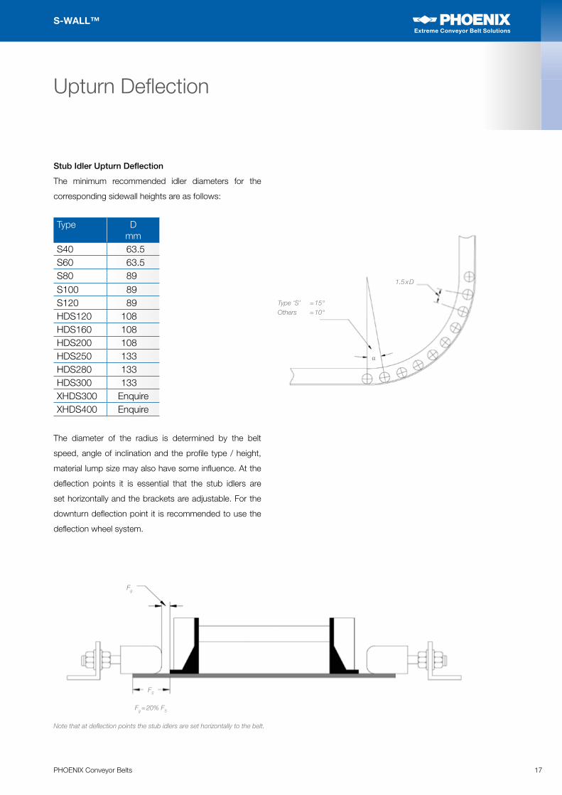
Stub Idler Upturn Deflection
The minimum recommended idler diameters for the
corresponding sidewall heights are as follows:
Type D mm
S40 63.5S60 63.5S80 89S100 89S120 89HDS120 108HDS160 108HDS200 108HDS250 133HDS280 133HDS300 133XHDS300 EnquireXHDS400 Enquire
The diameter of the radius is determined by the belt
speed, angle of inclination and the profile type / height,
material lump size may also have some influence. At the
deflection points it is essential that the stub idlers are
set horizontally and the brackets are adjustable. For the
downturn deflection point it is recommended to use the
deflection wheel system.
Type ‘S’ = 15°Others = 10°
Fg
Fg = 20% FS
FS
1.5 x D
α
Note that at deflection points the stub idlers are set horizontally to the belt.
18 PHOENIX Conveyor Belts
S-WALL™
Extreme Conveyor Belt Solutions
Extreme Conveyor Belt Solutions
Upturn Deflection
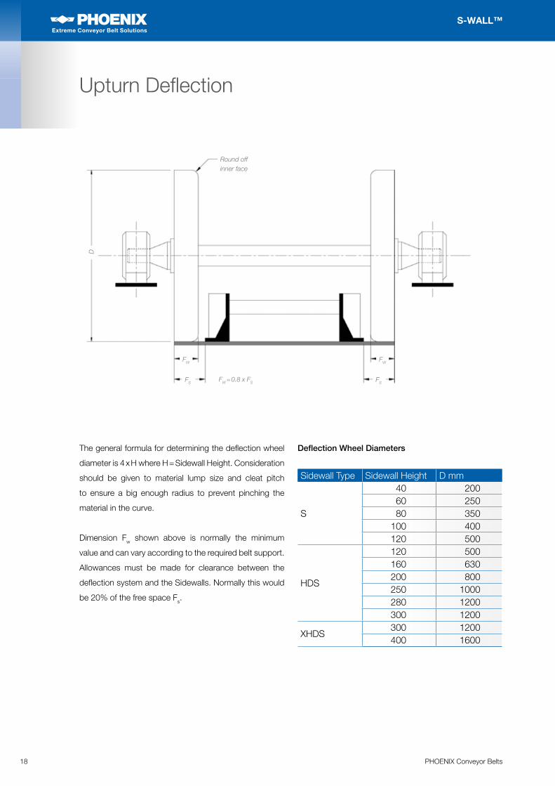
The general formula for determining the deflection wheel
diameter is 4 x H where H = Sidewall Height. Consideration
should be given to material lump size and cleat pitch
to ensure a big enough radius to prevent pinching the
material in the curve.
Dimension Fw shown above is normally the minimum
value and can vary according to the required belt support.
Allowances must be made for clearance between the
deflection system and the Sidewalls. Normally this would
be 20% of the free space Fs.
Deflection Wheel Diameters
Sidewall Type Sidewall Height D mm
S
40 20060 25080 350
100 400120 500
HDS
120 500160 630200 800250 1000280 1200300 1200
XHDS300 1200400 1600
Round off inner face
FW
FSFW = 0.8 x FS
D
FW
FS

19PHOENIX Conveyor Belts
S-WALL™
Extreme Conveyor Belt Solutions
Extreme Conveyor Belt Solutions
Top Deflection Curve
The change in angle can be achieved either by a series
of idlers positioned as per the sketch opposite or by a
single pulley.
The minimum recommended idler diameters for the
corresponding sidewall heights are as follows:
The amount of defection for
each idler depends on the
Sidewall type as follows:
Type S: Max 15°
Type HDS: Max 10°
Type XHDS: Max 10°
In addition the maximum
pitch of the idlers is set at
1.5 x D where D = Idler
Diameter.
The radius is determined by the belt speed and by the
method of deflection, angle of inclination, friction value of
the material and the profile type/height. The idler shaft
diameter must also take into account radial loadings
and may therefore need to be increased accordingly.
On installations with high lifts it may be necessary to
install small pulleys with external bearings.
Single Drum Deflection
Special care must be taken when selecting this method of
deflecting the belt, in particular the relationship between
belt speed and the material type. We have a computer
programme to determine the maximum belt speed for
the chosen pulley diameter for this point. Please enquire
regarding crowning of this pulley.
Note
Both systems need to be adjustable to allow for belt
tracking, please see the section on belt tracking on page 29.
Idler Deflection Curve
1.5 x D
It is beneficial to have these idlers mounted on a single plate to enable easier adjustment for belt tracking.
Type ‘S’ = 15°Others = 10°
α
Type D mm
S40 63.5S60 63.5S80 89S100 89S120 89HDS120 108HDS160 108HDS200 108HDS250 133HDS280 133HDS300 133XHDS300 EnquireXHDS400 Enquire
Single drum deflection.The drum should be adjustable in the direction of belt travel.
20 PHOENIX Conveyor Belts
S-WALL™
Extreme Conveyor Belt Solutions
Extreme Conveyor Belt Solutions
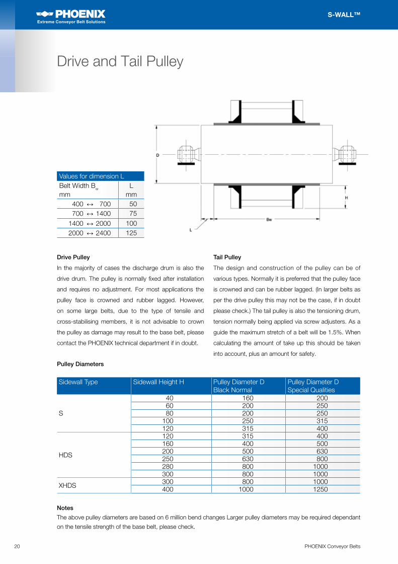
Drive and Tail Pulley
Values for dimension LBelt Width Bw mm
L mm
400 ↔ 700 50 700 ↔ 1400 75
1400 ↔ 2000 100 2000 ↔ 2400 125
Drive Pulley
In the majority of cases the discharge drum is also the
drive drum. The pulley is normally fixed after installation
and requires no adjustment. For most applications the
pulley face is crowned and rubber lagged. However,
on some large belts, due to the type of tensile and
cross-stabilising members, it is not advisable to crown
the pulley as damage may result to the base belt, please
contact the PHOENIX technical department if in doubt.
Tail Pulley
The design and construction of the pulley can be of
various types. Normally it is preferred that the pulley face
is crowned and can be rubber lagged. (In larger belts as
per the drive pulley this may not be the case, if in doubt
please check.) The tail pulley is also the tensioning drum,
tension normally being applied via screw adjusters. As a
guide the maximum stretch of a belt will be 1.5%. When
calculating the amount of take up this should be taken
into account, plus an amount for safety.
Pulley Diameters
Sidewall Type Sidewall Height H Pulley Diameter D
Black NormalPulley Diameter DSpecial Qualities
S
40 160 20060 200 25080 200 250
100 250 315120 315 400
HDS
120 315 400160 400 500200 500 630250 630 800280 800 1000300 800 1000
XHDS 300 800 1000400 1000 1250
Notes
The above pulley diameters are based on 6 million bend changes Larger pulley diameters may be required dependant
on the tensile strength of the base belt, please check.
21PHOENIX Conveyor Belts
S-WALL™
Extreme Conveyor Belt Solutions
Extreme Conveyor Belt Solutions
Pulley Crowning
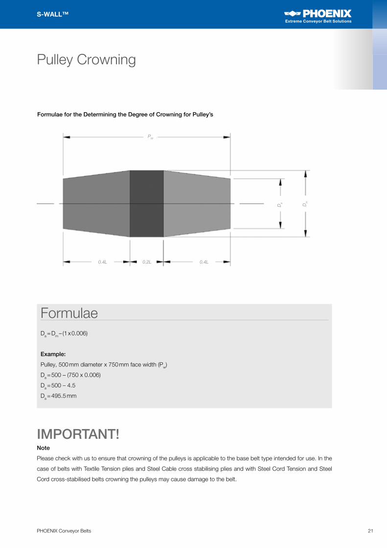
Formulae for the Determining the Degree of Crowning for Pulley’s
Note
Please check with us to ensure that crowning of the pulleys is applicable to the base belt type intended for use. In the
case of belts with Textile Tension plies and Steel Cable cross stabilising plies and with Steel Cord Tension and Steel
Cord cross-stabilised belts crowning the pulleys may cause damage to the belt.
IMPORTANT!
FormulaeDa = Dm – (1 x 0.006)
Example:
Pulley, 500 mm diameter x 750 mm face width (Pw)
Da = 500 – (750 x 0.006)
Da = 500 – 4.5
Da = 495.5 mm
Da
PW
0.4L
Dm
0.4L0.2L
22 PHOENIX Conveyor Belts
S-WALL™
Extreme Conveyor Belt Solutions
Extreme Conveyor Belt Solutions
Belt Snubbing
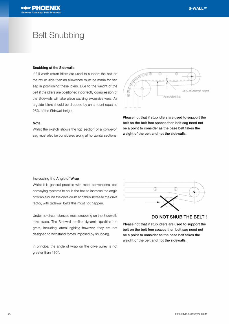
Snubbing of the Sidewalls
If full width return idlers are used to support the belt on
the return side then an allowance must be made for belt
sag in positioning these idlers. Due to the weight of the
belt if the idlers are positioned incorrectly compression of
the Sidewalls will take place causing excessive wear. As
a guide idlers should be dropped by an amount equal to
25% of the Sidewall height.
Note
Whilst the sketch shows the top section of a conveyor,
sag must also be considered along all horizontal sections.
Increasing the Angle of Wrap
Whilst it is general practice with most conventional belt
conveying systems to snub the belt to increase the angle
of wrap around the drive drum and thus increase the drive
factor, with Sidewall belts this must not happen.
Under no circumstances must snubbing on the Sidewalls
take place. The Sidewall profiles dynamic qualities are
great, including lateral rigidity; however, they are not
designed to withstand forces imposed by snubbing.
In principal the angle of wrap on the drive pulley is not
greater than 180°.
Please not that if stub idlers are used to support the
belt on the belt free spaces then belt sag need not
be a point to consider as the base belt takes the
weight of the belt and not the sidewalls.
Actual Belt line.
25% of Sidewall height
Please not that if stub idlers are used to support the
belt on the belt free spaces then belt sag need not
be a point to consider as the base belt takes the
weight of the belt and not the sidewalls.
DO NOT SNUB THE BELT !
23PHOENIX Conveyor Belts
S-WALL™
Extreme Conveyor Belt Solutions
Extreme Conveyor Belt Solutions
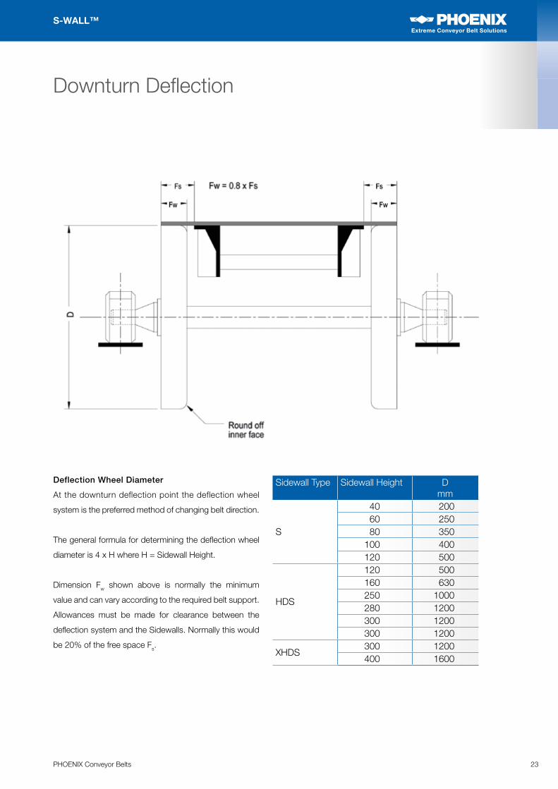
Sidewall Type Sidewall Height D mm
S
40 20060 25080 350
100 400120 500
HDS
120 500160 630250 1000280 1200300 1200300 1200
XHDS300 1200400 1600
Deflection Wheel Diameter
At the downturn deflection point the deflection wheel
system is the preferred method of changing belt direction.
The general formula for determining the deflection wheel
diameter is 4 x H where H = Sidewall Height.
Dimension Fw shown above is normally the minimum
value and can vary according to the required belt support.
Allowances must be made for clearance between the
deflection system and the Sidewalls. Normally this would
be 20% of the free space Fs.
Downturn Deflection
24 PHOENIX Conveyor Belts
S-WALL™
Extreme Conveyor Belt Solutions
Extreme Conveyor Belt Solutions
The change in angle can be achieved either by a series
of idlers positioned as the sketch opposite or by a single
pulley as per the top deflection curve.
The minimum recommended idler diameters for the
corresponding Sidewall heights are as follows:
As the loadings are normally
much lower at this point
conventional idlers will suffice.
The amount of deflection for
each idler depends on the
Sidewall type as follows:
Type S: Max 15°
Type HDS: Max 10°
Type XHDS: Max 10°
In addition the maximum pitch of the idlers is set at
1.5 x D where D = Idler Diameter.
Single Drum deflection.
The single drum system is the preferred means of
deflecting the belt at the bottom bend point. The drum
may be rubber lagged for better frictional contact with
the base belt aiding belt alignment at this point. For textile
belts the drum can be crowned, for steel cord belts the
drum must be flat without any crown.
The diameter of the drum is the same as the recommended
minimum pulley diameters for the drive and tail pulleys.
Note
Both systems need to be adjustable to allow for belt
tracking, please see the section on belt tracking on page 29.
Bottom Deflection Curve
Type S = 15°Other = 10°
1.5 x D
Idler deflection curve
It is beneficial to have these idlers mounted on a single plate to enable easier adjustment for belt tracking.
Single drum deflection.Drum is adjustable in the direction of belt travel.
Please see page 19 for details.
Type D mm
S40 63.5S60 63.5S80 89S100 89S120 89HDS120 108HDS160 108HDS200 108HDS250 133HDS280 133HDS300 133XHDS300 EnquireXHDS400 Enquire
25PHOENIX Conveyor Belts
S-WALL™
Extreme Conveyor Belt Solutions
Extreme Conveyor Belt Solutions
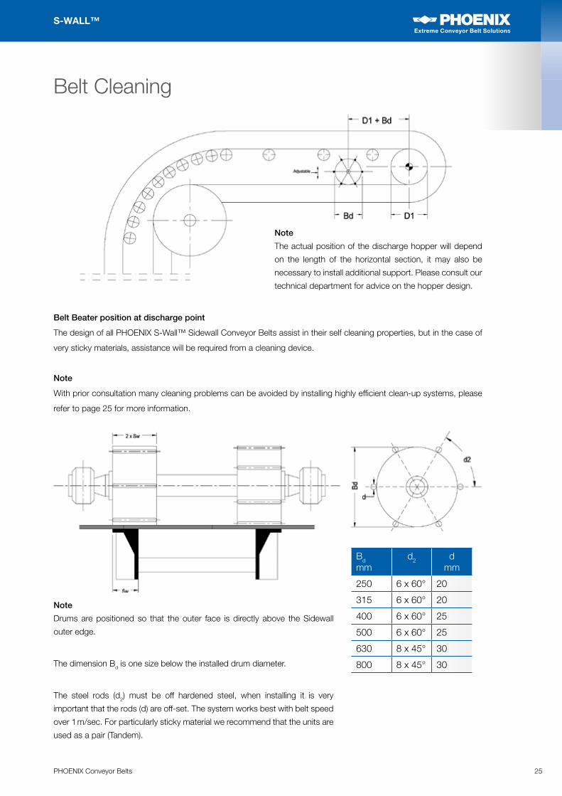
Belt Beater position at discharge point
The design of all PHOENIX S-Wall™ Sidewall Conveyor Belts assist in their self cleaning properties, but in the case of
very sticky materials, assistance will be required from a cleaning device.
Note
With prior consultation many cleaning problems can be avoided by installing highly efficient clean-up systems, please
refer to page 25 for more information.
Note
The actual position of the discharge hopper will depend
on the length of the horizontal section, it may also be
necessary to install additional support. Please consult our
technical department for advice on the hopper design.
Belt Cleaning
Note
Drums are positioned so that the outer face is directly above the Sidewall
outer edge.
The dimension Bd is one size below the installed drum diameter.
The steel rods (d2) must be off hardened steel, when installing it is very
important that the rods (d) are off-set. The system works best with belt speed
over 1 m/sec. For particularly sticky material we recommend that the units are
used as a pair (Tandem).
Bd mm
d2 d mm
250 6 x 60° 20
315 6 x 60° 20
400 6 x 60° 25
500 6 x 60° 25
630 8 x 45° 30
800 8 x 45° 30
26 PHOENIX Conveyor Belts
S-WALL™
Extreme Conveyor Belt Solutions
Extreme Conveyor Belt Solutions
Belt Cleaning
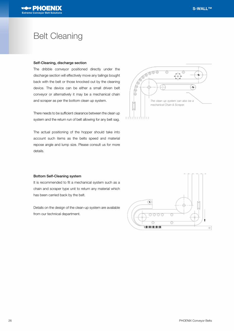
Self-Cleaning, discharge section
The dribble conveyor positioned directly under the
discharge section will effectively move any tailings bought
back with the belt or those knocked out by the cleaning
device. The device can be either a small driven belt
conveyor or alternatively it may be a mechanical chain
and scraper as per the bottom clean up system.
There needs to be sufficient clearance between the clean up
system and the return run of belt allowing for any belt sag.
The actual positioning of the hopper should take into
account such items as the belts speed and material
repose angle and lump size. Please consult us for more
details.
The clean up system can also be a mechanical Chain & Scraper.
Bottom Self-Cleaning system
It is recommended to fit a mechanical system such as a
chain and scraper type unit to return any material which
has been carried back by the belt.
Details on the design of the clean-up system are available
from our technical department.
27PHOENIX Conveyor Belts
S-WALL™
Extreme Conveyor Belt Solutions
Extreme Conveyor Belt Solutions
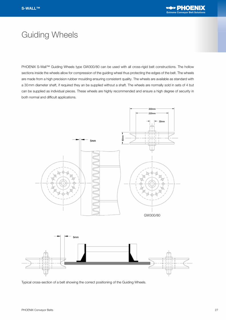
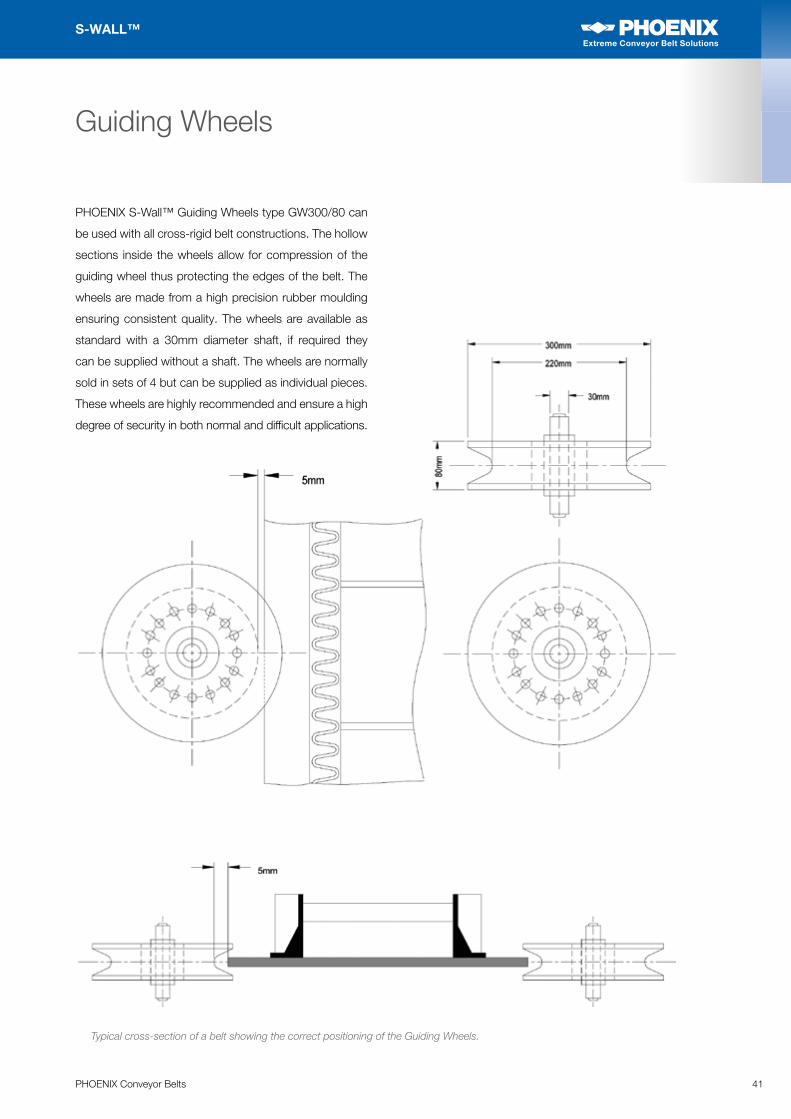
PHOENIX S-Wall™ Guiding Wheels type GW300/80 can be used with all cross-rigid belt constructions. The hollow
sections inside the wheels allow for compression of the guiding wheel thus protecting the edges of the belt. The wheels
are made from a high precision rubber moulding ensuring consistent quality. The wheels are available as standard with
a 30 mm diameter shaft, if required they an be supplied without a shaft. The wheels are normally sold in sets of 4 but
can be supplied as individual pieces. These wheels are highly recommended and ensure a high degree of security in
both normal and difficult applications.
Guiding Wheels
Guiding WheelsTypical cross-section of a belt showing the correct positioning of the Guiding Wheels.
GW300/80
28 PHOENIX Conveyor Belts
S-WALL™
Extreme Conveyor Belt Solutions
Extreme Conveyor Belt Solutions
Guiding Wheels
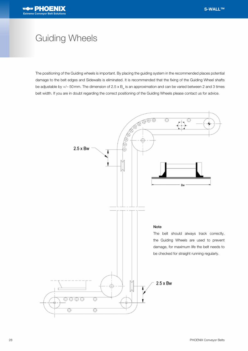
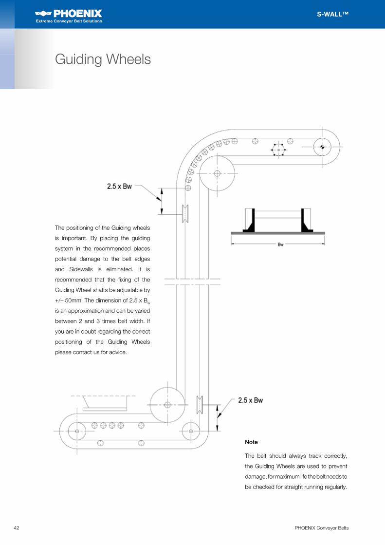
The positioning of the Guiding wheels is important. By placing the guiding system in the recommended places potential
damage to the belt edges and Sidewalls is eliminated. It is recommended that the fixing of the Guiding Wheel shafts
be adjustable by +/– 50 mm. The dimension of 2.5 x Bw is an approximation and can be varied between 2 and 3 times
belt width. If you are in doubt regarding the correct positioning of the Guiding Wheels please contact us for advice.
Note
The belt should always track correctly,
the Guiding Wheels are used to prevent
damage, for maximum life the belt needs to
be checked for straight running regularly.
29PHOENIX Conveyor Belts
S-WALL™
Extreme Conveyor Belt Solutions
Extreme Conveyor Belt Solutions
Belt Tracking
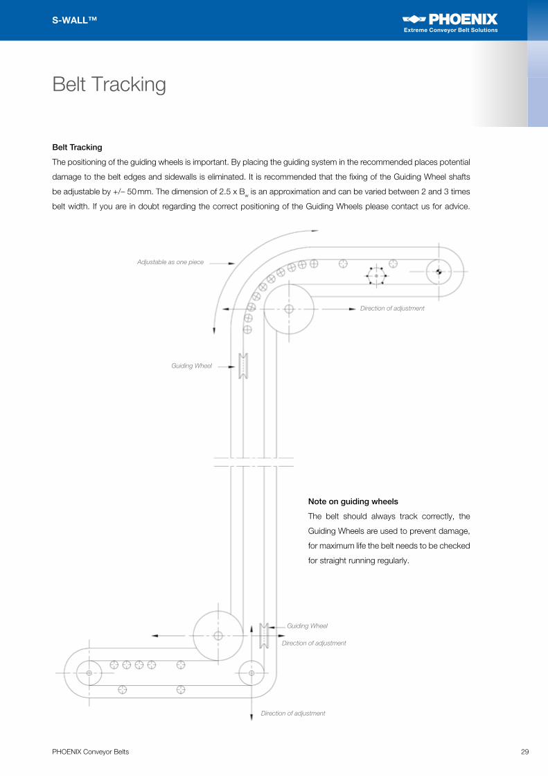
The positioning of the guiding wheels is important. By placing the guiding system in the recommended places potential
damage to the belt edges and sidewalls is eliminated. It is recommended that the fixing of the Guiding Wheel shafts
be adjustable by +/– 50 mm. The dimension of 2.5 x Bw is an approximation and can be varied between 2 and 3 times
belt width. If you are in doubt regarding the correct positioning of the Guiding Wheels please contact us for advice.
Note on guiding wheels
The belt should always track correctly, the
Guiding Wheels are used to prevent damage,
for maximum life the belt needs to be checked
for straight running regularly.
Belt Tracking
Adjustable as one piece
Direction of adjustment
Direction of adjustment
Direction of adjustment
Guiding Wheel
Guiding Wheel
30 PHOENIX Conveyor Belts
S-WALL™
Extreme Conveyor Belt Solutions
Extreme Conveyor Belt Solutions
Ancillary Equipment
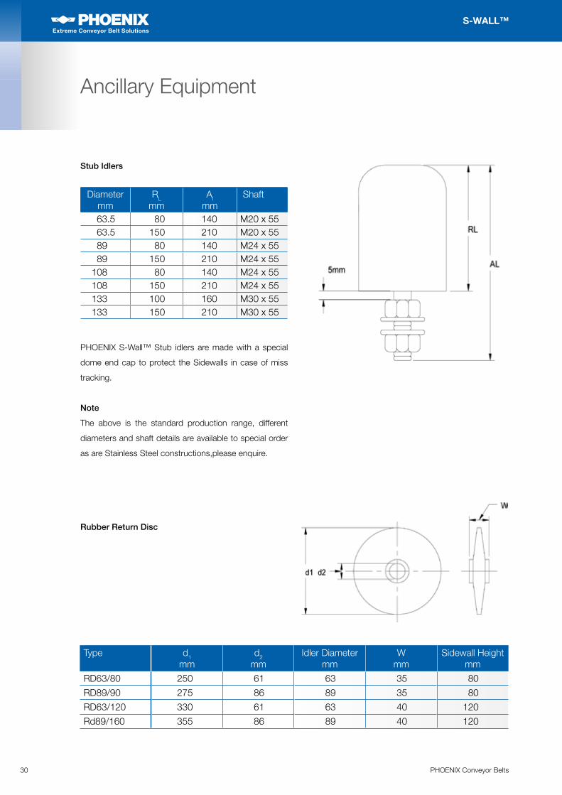
Stub Idlers
Diameter mm
RL
mmAl
mm Shaft
63.5 80 140 M20 x 5563.5 150 210 M20 x 5589 80 140 M24 x 5589 150 210 M24 x 55
108 80 140 M24 x 55108 150 210 M24 x 55133 100 160 M30 x 55133 150 210 M30 x 55
PHOENIX S-Wall™ Stub idlers are made with a special
dome end cap to protect the Sidewalls in case of miss
tracking.
Note
The above is the standard production range, different
diameters and shaft details are available to special order
as are Stainless Steel constructions,please enquire.
Rubber Return Disc
Type d1 mm
d2 mm
Idler Diameter mm
W mm
Sidewall Height mm
RD63/80 250 61 63 35 80
RD89/90 275 86 89 35 80
RD63/120 330 61 63 40 120
Rd89/160 355 86 89 40 120
31PHOENIX Conveyor Belts
S-WALL™
Extreme Conveyor Belt Solutions
Extreme Conveyor Belt Solutions
Installation and Jointing Procedure 32
Sidewall Head Joining 34
Belt Splicing Diagrams 36
Belt Handling 39
Tracking Instructions 40
Guiding Wheels 41
Maintenance and Enquiry Forms 43
Installation, Tracking and Maintenance
Note
This manual is intended to give outline information only, due to the nature of site installation of conveyor belts it is
not possible to cover for all eventualities. You are strongly recommended to check with our Service or Technical
Departments if you are unsure about any aspect of the information given within this manual.
32 PHOENIX Conveyor Belts
S-WALL™
Extreme Conveyor Belt Solutions
Extreme Conveyor Belt Solutions
Jointing Instructions
The S-Wall™ conveyor belt incorporated with your
conveyor system will provide long term service if correctly
installed and maintained. Our experience shows that belt
failures only occur where the installation is incorrect and
where there is insufficient maintenance. In most cases,
the belt specification selected has been the result of close
co-operation with the designers and/or the manufacturers
of the complete system. To ensure the success of the
S-Wall™ Conveyor, the following instructions should be
adhered to:
A. Initial Installation
1. Unpack the belt according to our information sheet
on belt handling.
2. Ensure tail take-up pulley is at its’ minimum position.
3. Thread belt round head and tail pulleys. (Where ‘C’
or ‘TC’ type inclined cleats are used, ensure these
point in the direction of belt travel.)
4. Select the best position on the conveyor where the
ends are to be spliced.
5. Clamp to the conveyor structure the trailing end of
the belt. The clamp should be positioned 1.5/2.0 m
from the end of the belt.
6. On the leading end of the belt, attach a tensioning
device 2.0 m from the end. Tensioning the belt to
remove as much sag as possible.
B. Jointing Procedure. (by splicing)
1. Place in position the bottom half of the vulcanising
press.
2. Place both ends of belt over vulcanising platten
ensuring the leading end is on top.
3. Remove excess belting and leave the overlap in
accordance with the relevant splicing diagram.
4. Step-down the ends of the belt, accordingly to the
measurements in the attached diagram, ensuring
the leading end is folded back and stripped from the
bottom and the trailing end is left on the vulcanising
platten and stripped from the top.
5. Remove all remaining pieces of cured rubber from
the exposed fabric without causing damage.
6. Apply vulcanizing solution to both ends (skin-gum to
trailing end which has been stripped from the top),
and bottom filler strip.
7. Place both ends of belt together, ensuring they are in
line with the belt, and insert top filler strip.
8. Position a sheet of cellophane paper over the joint;
lay a rubber mat over this and place in position on
the top half of the vulcanising press and secure (as
is common practice with all belt splicing, steelbars
approximately 1mm thinner than the thickness of the
belt itself must be positioned along the edges of the
joint and secured).
9. Apply correct pressure, and follow vulcanising
procedure in accordance with the quality of the belt.
10. Split and remove the vulcanising press at the required
temperature; remove all excess rubber along the
edges and the filler strip area.
11. Remove clamps and tensioning device.
12. Re-roughen thoroughly those areas where Sidewalls
and cleats are to be fitted, using a rectangular hard
board section under the belt to form a working base.
C. Joining Procedure (by fasteners)
1. Ensure ends are cut perfectly square and ‘butt up’
against each other.
2. Install fasteners to suit thickness and tensions,
ensuring that the pulley diameters are sufficiently
large.
3. Remove clamps and tensioning device.
4. Re-roughen where necessary those areas where
Sidewalls and cleats are to be fitted.
D. Finishing of Sidewalls and Cleats over Joint Area
1. Place loose ends of the S-Wall™ Sidewalls across
the joint area, matching the two ends and cutting
33PHOENIX Conveyor Belts
S-WALL™
Extreme Conveyor Belt Solutions
Extreme Conveyor Belt Solutions
in accordance with the diagram attached, i.e., so
that the profile is one continuous curved line and not
interrupted.
2. With a rotating wire brush, taper the two surfaces to
be joined, so that when joined together, they form
the same shape and thickness as the other parts of
the Sidewalls.
3. All roughened areas of Sidewalls, base belt, and
cleats, which are to have the cold cure adhesive
applied must be cleaned by “Secondary Buffing”.
This process of using say a motor with flexible shaft
and wire brush freshens the rubber by removing dust
and oxidization.
DO NOT USE ANY SOLVENTS TO CLEAN THE
RUBBER, THESE MAY EFFECT THE BOND
STRENGTH.
4. All these surfaces should be painted with two coats
of adhesive. After the first coat has been applied, it
should be left to dry for approx. 60 minutes before
applying the second coat.
5. When the second coat is almost dry, but feeling
slightly tacky, the parts to be joined are placed
together in the following way:
I. A clean 10 cm wide strip of cellophane is
placed a long that part of base belt where the
Sidewalls are to be bonded. This enables the
two matching end faces of the Sidewalls to be
joined together as closely and accurately as
possible.
II. When these faces are joined, they are pressed
together using shaped pieces of wood.
III. The strip of cellophane paper is then removed
and the base of the Sidewall is bonded to the
base belt.
IV. Next the top of the Sidewall is then hammered
with a rubber mallet to expel any trapped air.
V. Following this the base of the Sidewall is then
hammered with a shaped piece of wood.
VI. The outer lip of the Sidewall base is rolled with
a small steel roller to form a seal along the edge
of the Side wall and base belt.
VII. The two joined end faces of the S-Wall™
Sidewalls are then compressed together using
pliers or similar hand tools.
VIII. For additional security 2 steel plates with bolts
are supplied with the belt to join the Sidewall
heads.
6. The second coat of adhesive is then applied to the
cleats and the areas of the base belt where cleats
are to be fitted. Again, when this second coat is
almost dry, but still feeling slightly tacky, the parts to
be joined are placed together in the following way:
I. The cleats are placed in their correct position.
II. The upstand of the cleat is hammered securely
with a rubber mallet.
III. The base of the cleat is rolled with a steel hand
roller, starting against the upstand, and gradually
working across to the outer edges of the base.
IV. Using a shaped piece of wood with a base
of approx. 35 mm square, the cleat base is
hammered firmly until the whole base area of
the cleat has been covered.
REMEMBER
1. Once areas to be bonded are placed together, they
must not be moved.
2. The belt should not be moved or tensioned for 12 hours,
the time necessary for the bond to cure completely,
giving full strength, in the case of Heat Resistant belts
this may need to be extended, please enquire.
3. The majority of S-Wall™ belt failures are due to
incorrect joining of Sidewalls and cleats, therefore it is
essential these instructions are carried out explicitly.
4. In more difficult locations the use of a ‘Bonding
Layer’ will increase bond strength, please enquier
with our service dept for details.
Jointing Instructions
34 PHOENIX Conveyor Belts
S-WALL™
Extreme Conveyor Belt Solutions
Extreme Conveyor Belt Solutions
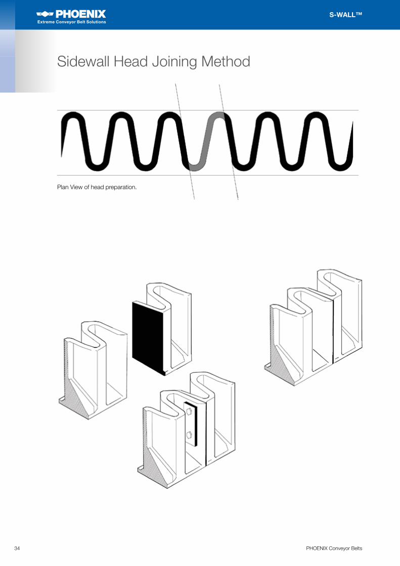
Plan View of head preparation.
Sidewall Head Joining Method
35PHOENIX Conveyor Belts
S-WALL™
Extreme Conveyor Belt Solutions
Extreme Conveyor Belt Solutions
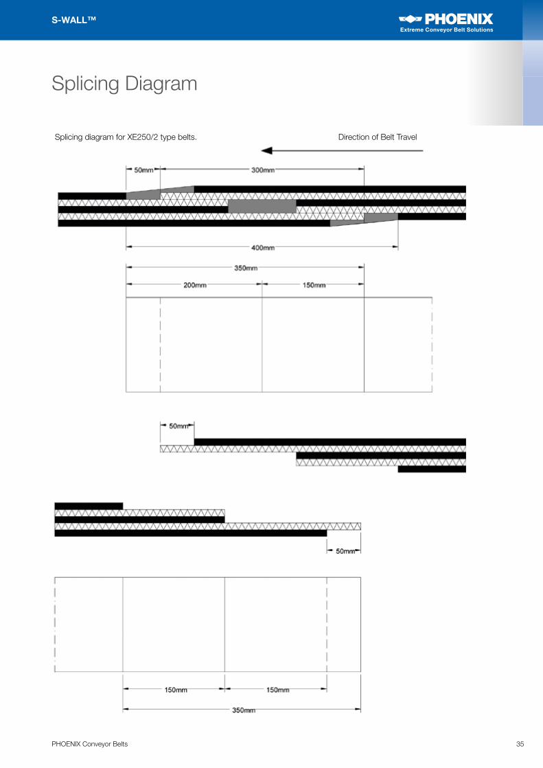
Splicing Diagram
Splicing diagram for XE250/2 type belts. Direction of Belt Travel
36 PHOENIX Conveyor Belts
S-WALL™
Extreme Conveyor Belt Solutions
Extreme Conveyor Belt Solutions
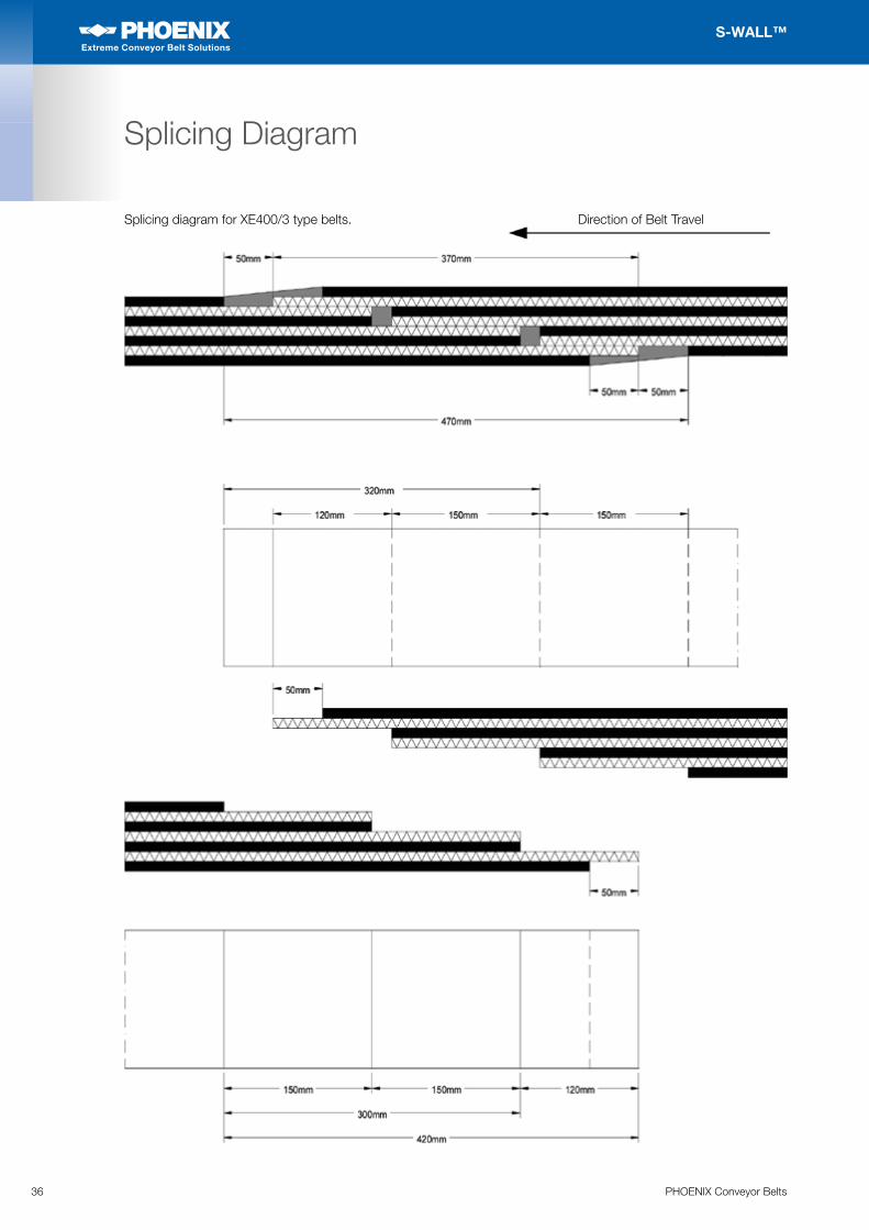
Splicing Diagram
Splicing diagram for XE400/3 type belts. Direction of Belt Travel
37PHOENIX Conveyor Belts
S-WALL™
Extreme Conveyor Belt Solutions
Extreme Conveyor Belt Solutions
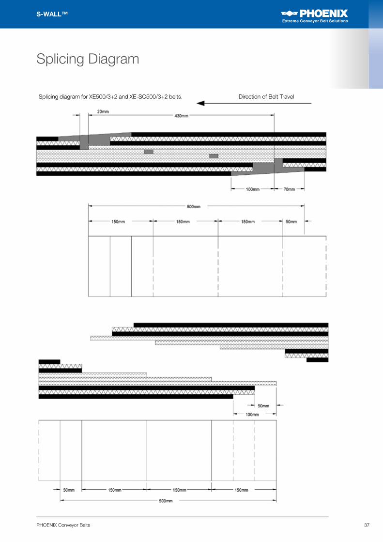
Splicing Diagram
Splicing diagram for XE500/3+2 and XE-SC500/3+2 belts. Direction of Belt Travel
38 PHOENIX Conveyor Belts
S-WALL™
Extreme Conveyor Belt Solutions
Extreme Conveyor Belt Solutions
Splicing Diagram
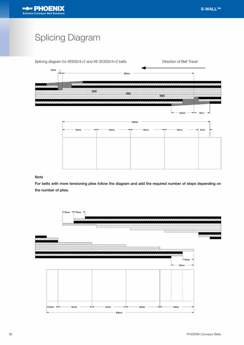
Note
For belts with more tensioning plies follow the diagram and add the required number of steps depending on
the number of plies.
Splicing diagram for XE630/4+2 and XE-SC630/4+2 belts Direction of Belt Travel
39PHOENIX Conveyor Belts
S-WALL™
Extreme Conveyor Belt Solutions
Extreme Conveyor Belt Solutions
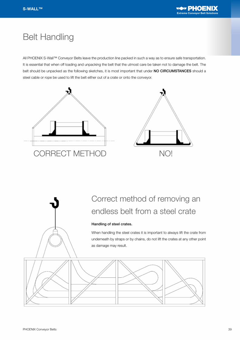
Belt Handling
All PHOENIX S-Wall™ Conveyor Belts leave the production line packed in such a way as to ensure safe transportation.
It is essential that when off loading and unpacking the belt that the utmost care be taken not to damage the belt. The
belt should be unpacked as the following sketches, it is most important that under NO CIRCUMSTANCES should a
steel cable or rope be used to lift the belt either out of a crate or onto the conveyor.
CORRECT METHOD NO!
Correct method of removing an
endless belt from a steel crate Handling of steel crates.
When handling the steel crates it is important to always lift the crate from
underneath by straps or by chains, do not lift the crates at any other point
as damage may result.
40 PHOENIX Conveyor Belts
S-WALL™
Extreme Conveyor Belt Solutions
Extreme Conveyor Belt Solutions
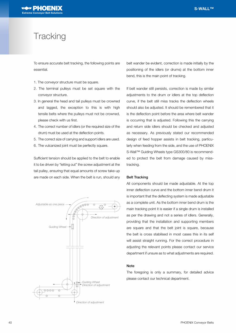
Tracking
To ensure accurate belt tracking, the following points are
essential.
1. The conveyor structure must be square.
2. The terminal pulleys must be set square with the
conveyor structure.
3. In general the head and tail pulleys must be crowned
and lagged, the exception to this is with high
tensile belts where the pulleys must not be crowned,
please check with us first.
4. The correct number of idlers (or the required size of the
drum) must be used at the deflection points.
5. The correct size of carrying and support idlers are used.
6. The vulcanized joint must be perfectly square.
Sufficient tension should be applied to the belt to enable
it to be driven by “letting out” the screw adjustment at the
tail pulley, ensuring that equal amounts of screw take-up
are made on each side. When the belt is run, should any
belt wander be evident, correction is made initially by the
positioning of the idlers (or drums) at the bottom inner
bend, this is the main point of tracking.
If belt wander still persists, correction is made by similar
adjustments to the drum or idlers at the top deflection
curve, if the belt still miss tracks the deflection wheels
should also be adjusted. It should be remembered that it
is the deflection point before the area where belt wander
is occurring that is adjusted. Following this the carrying
and return side idlers should be checked and adjusted
as necessary. As previously stated our recommended
design of feed hopper assists in belt tracking, particu-
larly when feeding from the side, and the use of PHOENIX
S-Wall™ Guiding Wheels type GS300/80 is recommend-
ed to protect the belt from damage caused by miss-
tracking.
Belt Tracking
All components should be made adjustable. At the top
inner deflection curve and the bottom inner bend drum it
is important that the deflecting system is made adjustable
as a complete unit. As the bottom inner bend drum is the
main tracking point it is easier if a single drum is installed
as per the drawing and not a series of idlers. Generally,
providing that the installation and supporting members
are square and that the belt joint is square, because
the belt is cross stabilised in most cases this in its self
will assist straight running. For the correct procedure in
adjusting the relevant points please contact our service
department if unsure as to what adjustments are required.
Note
The foregoing is only a summary, for detailed advice
please contact our technical department.
Adjustable as one piece
Direction of adjustment
Direction of adjustment
Guiding Wheel
Guiding Wheel
Direction of adjustment
41PHOENIX Conveyor Belts
S-WALL™
Extreme Conveyor Belt Solutions
Extreme Conveyor Belt Solutions
Guiding Wheels
PHOENIX S-Wall™ Guiding Wheels type GW300/80 can
be used with all cross-rigid belt constructions. The hollow
sections inside the wheels allow for compression of the
guiding wheel thus protecting the edges of the belt. The
wheels are made from a high precision rubber moulding
ensuring consistent quality. The wheels are available as
standard with a 30mm diameter shaft, if required they
can be supplied without a shaft. The wheels are normally
sold in sets of 4 but can be supplied as individual pieces.
These wheels are highly recommended and ensure a high
degree of security in both normal and difficult applications.
Typical cross-section of a belt showing the correct positioning of the Guiding Wheels.
42 PHOENIX Conveyor Belts
S-WALL™
Extreme Conveyor Belt Solutions
Extreme Conveyor Belt Solutions
Guiding Wheels
The positioning of the Guiding wheels
is important. By placing the guiding
system in the recommended places
potential damage to the belt edges
and Sidewalls is eliminated. It is
recommended that the fixing of the
Guiding Wheel shafts be adjustable by
+/– 50mm. The dimension of 2.5 x Bw
is an approximation and can be varied
between 2 and 3 times belt width. If
you are in doubt regarding the correct
positioning of the Guiding Wheels
please contact us for advice.
Note
The belt should always track correctly,
the Guiding Wheels are used to prevent
damage, for maximum life the belt needs to
be checked for straight running regularly.
43PHOENIX Conveyor Belts
S-WALL™
Extreme Conveyor Belt Solutions
Extreme Conveyor Belt Solutions
Maintenance and Enquiry Form
The storing of S-Wall™ belts is also an important factor. They must be kept on the steel or wooden crates in which they
are delivered, ensuring that the loops are not compressed by the weight of the belt. Ideally, the belts should be stored
in normal factory conditions, away from the direct sunlight and heat. Please see DIN 7716 which is available on request
for details on the recommended storage practice for rubber goods.
Idlers: These must rotate freely, and be free from any
material build-up. Lubrication of all moving parts on a
planned basis is essential for dependable operation and
minimum maintenance. Component life will be extended
by following the manufacturer lubrication instructions.
Pulleys: These should be free from any material build-up.
The lagging on the drive pulley should be inspected on
a regular basis. If the lagging is in poor condition it may
be necessary to apply more tension than is normally
necessary to drive the belt resulting in premature wear.
Deflection Gear: Again, these must be free to rotate
freely.
Feed Hopper: It is important that this is just free from
the top of the S-Wall™ Sidewalls, any rubber seals
around the hopper need checking for wear to prevent
excessive dust or spillage.
Tracking: The belt should run without touching any side
members or deflection gear, please refer to the section
on belt tracking if the belt is running out of alignment.
Good housekeeping: This is necessary for continuous
operation and low maintenance. Spillage and build up of
material can eventually cause the idlers to stop rotating
and an accumulation of lumpy material can cause belt
damage.
Check: The belt edges, Sidewalls, Cleats and the belt
splice need to be checked on a periodic basis for wear
or separation. Any minor areas of damage should be
repaired as soon as is possible.
Contract: A maintenance contract may be available for
your S-Wall™ belt either on a direct basis from PHOENIX
Conveyor Belt Systems or from your local PHOENIX
Conveyor Belt Systems approved service company,
please ask for details.
Maintenance costs on conveyors are less than on ordinary troughed belt conveyors and bucket elevators, but it should
be remembered that anything between 25% and 50% of the initial cost of the conveyor can be attributed to the cost of
the belt, whereas troughed conveyors may only amount to 10% to 15%. Therefore it can be seen that the replacement
of a S-Wall™ belt is an expensive operation, and it is in your interests to ensure that all S-Wall™ belts are regularly
inspected for signs of wear caused by mechanical damage and spillage.
REMEMBER, most belts are torn out rather than worn out. In particular, the following points should be noted:
Enquiry FormA careful study of simple and most difficult applications is all time guaranteed
through the support of the Application Technology from PHOENIX Conveyor Belts.
Please contact us for an individual offer.
Please use our online forms: www.phoenix-conveyor-belts.com/belt-enquiry
Extreme Conveyor Belt Solutions
Extreme Conveyor Belt Solutions
The content of this publication is provided for information only and without responsibility. PHOENIX Conveyor Belt Systems
GmbH’s obligations and responsibilities regarding its products are governed solely by the agreements under which the products
are sold. Unless otherwise agreed in writing, the information contained herein does not become part of these agreements. This
publication does not contain any guarantee or agreed quality of PHOENIX Conveyor Belt Systems GmbH’s products or any
warranty of merchantability, fitness for a particular purpose and noninfringement. PHOENIX Conveyor Belt Systems GmbH
may make changes in the products or services described at any time without notice. This publication is provided on an “as
is” basis. To the extent permitted by law, PHOENIX Conveyor Belt Systems GmbH makes no warranty, express or implied,
and assumes no liability in connection with the use of the information contained in this publication. PHOENIX Conveyor
Belt Systems GmbH is not liable for any direct, indirect, incidental, consequential or punitive damages arising out of the
use of this publication. Information contained herein is not intended to announce product availability anywhere in the world.
© 2018 PHOENIX Conveyor Belt Systems GmbH. All rights reserved.
PHOENIX Conveyor Belt Systems GmbH
Hannoversche Straße 100
21079 Hamburg
Germany
Ph: +49 (0)40 7667-03
Fax: +49 (0)40 7667-2413
www.phoenix-conveyorbelts.com
PHOENIX Conveyor Belt Systems GmbH has established a respected global market presence based upon innovative product design and cutting edge technology.
Our line of conveyor belt products is developed from engineered product designs that have been tested and proven to provide the highest level of performance in conveying applications worldwide. Dedication to all aspects of the manufacturing process and the highest level of quality control standards ensure that our products provide the best value to our customers. With over 100 years of experience and a multitude of world records, PHOENIX Conveyor Belt Systems GmbH continues to demonstrate its position as the global leaderin conveyor belt technology.