DS TFCOM REL. 1.0 - EPS Vertrieb
12
TFCOM TFCOM VOICE SYNTHESIS ETHERNET 1 2 3 4 5 6 7 8 ROUTER ETHERNET 1 2 3 4 5 6 7 8 ROUTER Dispositivi di espansione - Expansions - Extensions - Expansores 1 Phone dialer PSTN phone dialer, approved for use in combination with TFA fire detection systems. Integrated PSTN phone carrier. Optional phone carriers: GSM-GPRS. 8 communicators/channels for phone notification of events, 1 CALL BACK communicator/channel dedicated to the connection with the management centre. 33 categories of transmissible events. 5 types of transmissible zone events. 2 phone numbers or IP addresses for each communicator. 29 communication protocols functional to phone notification carriers. Transmission formats: Voice, SMS, Ring, DTMF, Data. Security: encrypted communication, supported encryptions AES 128 Bit and AES 256 Bit, independent passphrase setting for each communicator. Automatic diagnostic functions: communications carriers, power supply, battery, serial communication. Front panel with 6 LED signalling operating states. Fault output. Full RSC ® management of the device: setup, remote management and control of all functional parameters. Built-in flash memory for vocabulary customization, manageable from a personal computer as an external disk. USB interface. RS485 bus connection. Addressable device. Metallic enclosure. Class of protection IP30. Battery housing: 1 12V-7Ah. Dimensions (L x H x P) 315 x 255 x 82mm. Black. EN 54-21: 2006. Homologation certificate 0051-CPR–0454. Item no. TF2TFCOM The TFCOM phone dialer can be used only if connected to an expansion serial bus of the Tecnofire control units models: TFA1-298, TFA2-596 and TFA4-1192. During design and installation, it is necessary to observe and apply the applicable regulations. OBLIGATIONS AND NOTICES The TFCOM phone dialer allows to expand the transmission carriers and the phone notification communication methods of the following Systems:TFA1-298, TFA2-596 and TFA4-1192. The phone dialer belongs to the category "Expansion devices". The Systems TFA2-596 and TFA4-1192 can manage up to 16 expansion devices, the System TFA1-298 can manage up to 5 expansion devices. The telephone dialer can be connected according to the control unit used and to the System topology to the Master or Slave Bus, in open loop or closed loop mode. The System Buses are supervised, the control unit is able to detect and report a connection line break, with closed-loop configuration the control unit still maintains the normal operation of the network. The Tecnofire Systems can manage multiple TFCOM dialers. OVERVIEW TFA1-298 System communications carriers TFA2-596 and TFA4-1192 systems communications carriers Centrale antincendio Centrale in funzione Centrale antincendio Centrale in funzione
Transcript of DS TFCOM REL. 1.0 - EPS Vertrieb
TFCOM
TFCOM VOICESYNTHESIS
ETHERNET
1 2 3 4 5 6 7 8
ROUTER
ETHERNET
1 2 3 4 5 6 7 8
ROUTER
Dis
po
sit
ivi
di
es
pa
ns
ion
e -
Ex
pa
ns
ion
s -
Ex
ten
sio
ns
- E
xp
an
so
res
1
Phone dialer
PSTN phone dialer, approved for use in combination with TFA fire detection systems. Integrated PSTN phone carrier. Optional phone carriers: GSM-GPRS. 8 communicators/channels for phone notification of events, 1 CALL BACK communicator/channel dedicated to the connection with the management centre. 33 categories of transmissible events. 5 types of transmissible zone events. 2 phone numbers or IP addresses for each communicator. 29 communication protocols functional to phone notification carriers. Transmission formats: Voice, SMS, Ring, DTMF, Data. Security: encrypted communication, supported encryptions AES 128 Bit and AES 256 Bit, independent passphrase setting for each communicator. Automatic diagnostic functions: communications carriers, power supply, battery, serial communication.Front panel with 6 LED signalling operating states. Fault output. Full RSC® management of the device: setup, remote management and control of all functional parameters. Built-in flash memory for vocabulary customization, manageable from a personal computer as an external disk. USB interface.RS485 bus connection. Addressable device. Metallic enclosure. Class of protection IP30.Battery housing: 1 12V-7Ah. Dimensions (L x H x P) 315 x 255 x 82mm. Black.EN 54-21: 2006. Homologation certificate 0051-CPR–0454.
Item no. TF2TFCOM
The TFCOM phone dialer can be used only if connected to an expansion serial bus of the Tecnofire control units models: TFA1-298, TFA2-596 and TFA4-1192.During design and installation, it is necessary to observe and apply the applicable regulations.
OBLIGATIONS AND NOTICES
The TFCOM phone dialer allows to expand the transmission carriers and the phone notification communication methods of the following Systems:TFA1-298, TFA2-596 and TFA4-1192.The phone dialer belongs to the category "Expansion devices". The Systems TFA2-596 and TFA4-1192 can manage up to 16 expansion devices, the System TFA1-298 can manage up to 5 expansion devices.The telephone dialer can be connected according to the control unit used and to the System topology to the Master or Slave Bus, in open loop or closed loop mode.The System Buses are supervised, the control unit is able to detect and report a connection line break, with closed-loop configuration the control unit still maintains the normal operation of the network. The Tecnofire Systems can manage multiple TFCOM dialers.
OVERVIEW
TFA1-298 System communications carriers
TFA2-596 and TFA4-1192 systems communications carriers
0
1 2 3
4 5 6
8 97
allaRME
PREallaRME
allaRME TECNICO
GUASTO
GUASTO ALIMENT.
GUASTO SISTEMA
BATTERIA
SIRENE TACITATE
ESCLUSIONE
GUASTO/ESCL SIRENA
GUASTO/ESCL COM
ZONE IN TEST
PRESIDIATO
PRESENZA RETE
DISPOSITIVI IN RETE
TRASMISSIONE AVVENUTA
Ok
ESC
Back
EVACUAZ.
PRESIDIATO
TACITAZ.
TAC/RIPSIRENE
RIPRISTINO
Livello 2 Livello 3 Livello 4
28/05/2015 08:00:00Livello di accesso 1
Centrale antincendio
Versione: 1.2.00 ITA
Centrale in funzione
TFCOMD
isp
os
itiv
i d
i e
sp
an
sio
ne
- E
xp
an
sio
ns
- E
xte
ns
ion
s -
Ex
pa
ns
ore
s
PSTNGSM-GPRSSM GPRSRSSM GPPRRGGSM-GPRSS
TFCOM
CMSSERVICE
CMSSERVICE
2
Phone dialer
ADDRESSING AND IDENTIFICATION
The serial identification physical address of the TFCOM phone dialer is set via the SW2 Dip-switch located inside the cabinet, on the motherboard where the cables are connected.The TFCOM dialer is an expansion device, the numeric range of the addresses allowed for the expansion devices is address 1 to 16. Please note that setting address 0 disables the dialer. The address set on the dialer must be enabled from the relevant "Repeaters Setup" menu of the control unit. Access to the menu is allowed only to users provided with Level 3 password.
Access level 3
Menu Confi guration repeaterEnabling EnabledDescription Voice msgType Channel
10:10:5612/10/2016
Selection of the type of Repeater
Dialer TFCOM Dialer
Repeater TFT-7 repeater panel
Dashboard TFT-7S dashboard repeater panel
Repeater title menu
Repeaters Setup
Enabling Enabled or Disabled
Description Menu to enter alphanumeric description
Voice msg Menu to select the voice message
Type Selection of the type of Repeater
Repeater phrase menu
Word
Selection of 4 words that make up the voice message that identifi es the device
Word
Word
Word
Enables or disables the Repeater
Enabled The Repeater is enabled
Disabled The Repeater is disabled
The connection line is balanced, the balance must be set by dip switches or jumpers only on the last device connected.To connect the devices it is mandatory to use multipolar shielded cable with flexible wires. The signal connection wires A and B must be twisted. The maximum length allowed for Bus lines of the system is 1000mt. You can achieve greater distances using an optical fiber connection instead of an electric cable.For reasons of electrical safety and to improve the immunity to interferences, the shielding of the cables must be connected so as not to break their path and must be connected to the ground terminal only inside the fire detection control unit.
Bus extension / cable specifi cations
Max. extension 1000 m Minimum section Electrical resistance
Power supply wires 2 x 1.5 mm² <13,3 Ohm x Km
Signal wires 2 x 1 mm² <19,5 Ohm x Km
CONNECTION TO THE SERIAL LINE
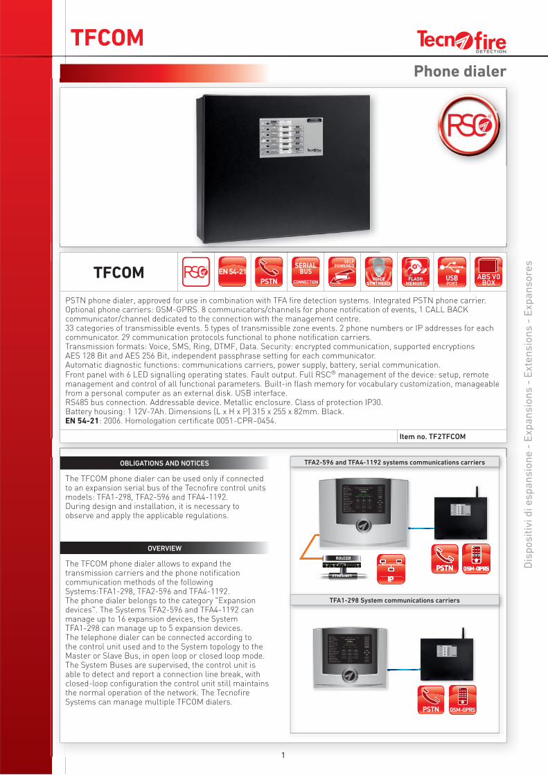
Important Notice Here are the literal contents of the requirements of the applicable standard UNI 9795: 2013, paragraph 5.5.3.2. When the control unit is not under constant monitoring by the personnel involved, there must be a system through which fire and fault alarms and out of service notifications shall be transferred to one or multiple alarm units for alarm receipt and intervention and/
REGULATED BY UNI9795: 2013
or manned places, from which the employees can implement at any time and in a timely manner the necessary measures.The connection with the above units must be constantly monitored, so the devices used must comply with EN 54-21.
0
1 2 3
4 5 6
8 97
allaRME
PREallaRME
allaRME TECNICO
GUASTO
GUASTO ALIMENT.
GUASTO SISTEMA
BATTERIA
SIRENE TACITATE
ESCLUSIONE
GUASTO/ESCL SIRENA
GUASTO/ESCL COM
ZONE IN TEST
PRESIDIATO
PRESENZA RETE
DISPOSITIVI IN RETE
TRASMISSIONE AVVENUTA
Ok
ESC
Back
EVACUAZ.
PRESIDIATO
TACITAZ.
TAC/RIPSIRENE
RIPRISTINO
Livello 2 Livello 3 Livello 4
28/05/2015 08:00:00Livello di accesso 1
Centrale antincendio
Versione: 1.2.00 ITA
Centrale in funzione
TFCOM
Dis
po
sit
ivi
di
es
pa
ns
ion
e -
Ex
pa
ns
ion
s -
Ex
ten
sio
ns
- E
xp
an
so
res
3
Phone dialer
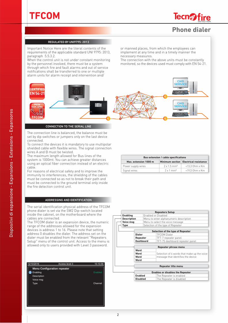
The control unit manages a set of specific diagnostic functions for the expansion devices.The diagnostic functions that are available for the phone dialer allow to:- Identify the equipment and versions of the resources.- Read the statistics from the communication monitor- Monitor the value of the power voltage.
DIAGNOSTIC FUNCTIONS
Power supply monitor
Supply voltage Detects the external power supply
Battery voltage Detects the battery supply
Statistics
Frames sent Communication frames counter
Errors Faulty frames counter
Success Rate Percent value
Error rate Percent value
Versions
Firmware Device fi rmware version
Writings Set of writings used
Dictionary Dictionary version
Serial number Serial number of the device
Licences Enabling string
Access level 3
Menu Test repeater VersionsStatisticsPower monitorChannel monitor
10:10:5612/10/2016
H. 255mm
L. 315mm
H. 80mm
Dialer Monitor
PSTN Device status (Enabled-Disabled)
GSM Device status (Enabled-Disabled)
GSM Status Registration to the mobile phone network
Operator Displays the phone carrier ID
Field Displays the GSM signal level
Firmware Device fi rmware version
Repeater testVersions Resource equipment and version
Statistics Communication monitor statistics
Power monitor Power supply sources monitor
Channel monitor Functional monitor of the dialer
L. 82mm
JP10BATT
LED LINELED RUN
LED USB
USBPort
TTLPort
JP4BOOT
JP5PROG
JP2RESET
JP1WDT
JP8RS485
TFCOMD
isp
os
itiv
i d
i e
sp
an
sio
ne
- E
xp
an
sio
ns
- E
xte
ns
ion
s -
Ex
pa
ns
ore
s
4
Phone dialer
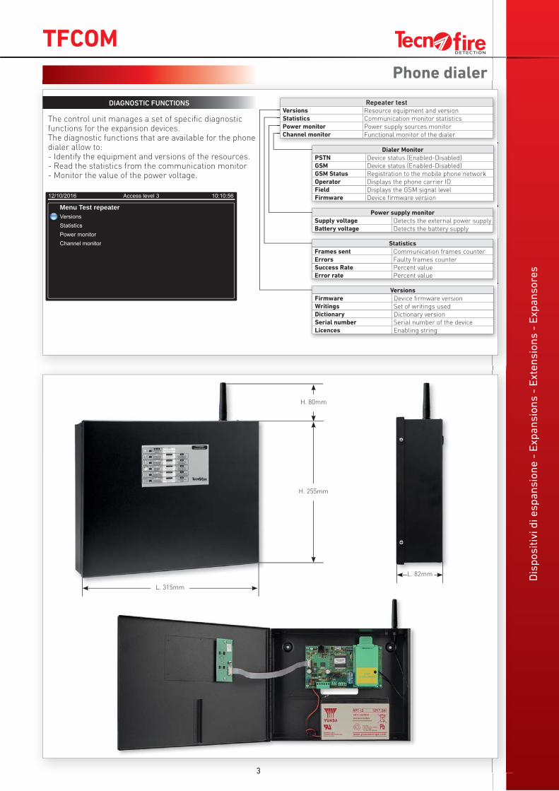
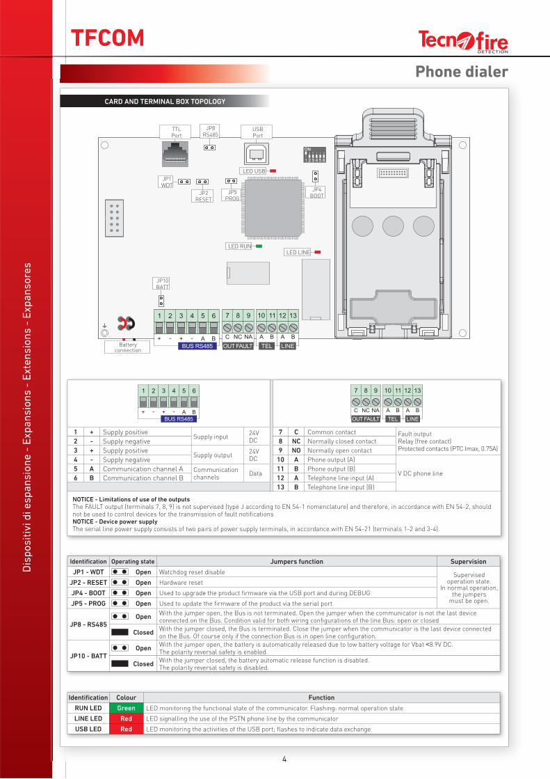
CARD AND TERMINAL BOX TOPOLOGY
1 + Supply positive Supply input
24V DC
7 C Common contact Fault outputRelay (free contact)Protected contacts (PTC Imax, 0.75A)
2 - Supply negative 8 NC Normally closed contact
3 + Supply positive Supply output
24V DC
9 NO Normally open contact
4 - Supply negative 10 A Phone output (A)
V DC phone line5 A Communication channel A Communication
channelsData
11 B Phone output (B)
6 B Communication channel B 12 A Telephone line input (A)
13 B Telephone line input (B)
NOTICE - Limitations of use of the outputsThe FAULT output (terminals 7, 8, 9) is not supervised (type J according to EN 54-1 nomenclature) and therefore, in accordance with EN 54-2, should not be used to control devices for the transmission of fault notifi cations NOTICE - Device power supplyThe serial line power supply consists of two pairs of power supply terminals, in accordance with EN 54-21 (terminals 1-2 and 3-4).
Identifi cation Colour Function
RUN LED Green LED monitoring the functional state of the communicator. Flashing: normal operation state
LINE LED Red LED signalling the use of the PSTN phone line by the communicator
USB LED Red LED monitoring the activities of the USB port; fl ashes to indicate data exchange
Identifi cation Operating state Jumpers function Supervision
JP1 - WDT Open Watchdog reset disable Supervised operation state.
In normal operation, the jumpers
must be open.
JP2 - RESET Open Hardware reset
JP4 - BOOT Open Used to upgrade the product fi rmware via the USB port and during DEBUG
JP5 - PROG Open Used to update the fi rmware of the product via the serial port
JP8 - RS485Open
With the jumper open, the Bus is not terminated. Open the jumper when the communicator is not the last device connected on the Bus. Condition valid for both wiring confi gurations of the line Bus: open or closed
ClosedWith the jumper closed, the Bus is terminated. Close the jumper when the communicator is the last device connected on the Bus. Of course only if the connection Bus is in open line confi guration.
JP10 - BATTOpen
With the jumper open, the battery is automatically released due to low battery voltage for Vbat ˂8.9V DC.The polarity reversal safety is enabled.
ClosedWith the jumper closed, the battery automatic release function is disabled.The polarity reversal safety is disabled.
Battery connection
TFCOM
Dis
po
sit
ivi
di
es
pa
ns
ion
e -
Ex
pa
ns
ion
s -
Ex
ten
sio
ns
- E
xp
an
so
res
PSTN disabilitatoPSTN disabled
GSM disabilitatoGSM disabled
VETTORE PSTNPSTN VECTOR
VETTORE GSMGSM VECTOR
ALIMENTAZIONEPOWER
Batteria bassaLow battery
Guasto BUS tacitatoBUS failure confirmed
Guasto alimentazionePower failure
BATTERIABATTERY
Guasto GSMGSM failure
Guasto PSTNPSTN failure
Guasto batteriaBattery failure
D E T E C T I O N
COLLOQUIO BUSCOMMUNICATION
TX NOTIFICHETX NOTIFICATIONS
Trasmissione in corsoTX active
Trasmissione OKTX OK
Guasto BUSBUS failure
5
Phone dialer
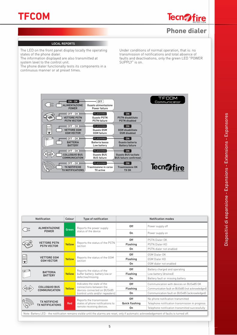
The LED on the front panel display locally the operating states of the phone dialer.The information displayed are also transmitted at system level to the control unit.The phone dialer functionally tests its components in a continuous manner or at preset times.
Under conditions of normal operation, that is: no transmission of notifications and total absence of faults and deactivations, only the green LED "POWER SUPPLY" is on.
LOCAL REPORTS
Notifi cation Colour Type of notifi cation Notifi cation modes
ALIMENTAZIONEPOWER
GreenReports the power supply status of the device
Off Power supply off
On Power supply on
VETTORE PSTNPSTN VECTOR
YellowReports the status of the PSTN section
Off PSTN Dialer OK
Flashing PSTN Dialer KO
On PSTN dialer not enabled
VETTORE GSMGSM VECTOR
YellowReports the status of the GSM section
Off GSM Dialer OK
Flashing GSM Dialer KO
On GSM dialer not enabled
BATTERIABATTERY
YellowReports the status of the buffer battery: battery low or defective/missing
Off Battery charged and operating
Flashing Low battery (drained)
On Battery fault or missing battery
COLLOQUIO BUSCOMMUNICATION
Yellow
Indicates the state of the connections between the devices connected on BUS485 (control units and/or repeaters)
Off Communication with devices on BUS485 OK
Flashing Communication fault on BUS485 (not acknowledged)
On Communication fault on BUS485 (acknowledged)
TX NOTIFICHETX NOTIFICATIONS
RedReports the transmission states of phone notifi cations to remote receiving devices.
Off No phone notifi cation transmitted
Quick fl ashing Telephone notifi cation transmission in progress
On Telephone notifi cation transmitted successfully
Note: Battery LED - the notifi cation remains visible until the alarms are reset, only if automatic acknowledgement of faults is turned off.
TFCOMD
isp
os
itiv
i d
i e
sp
an
sio
ne
- E
xp
an
sio
ns
- E
xte
ns
ion
s -
Ex
pa
ns
ore
s
6
Phone dialer
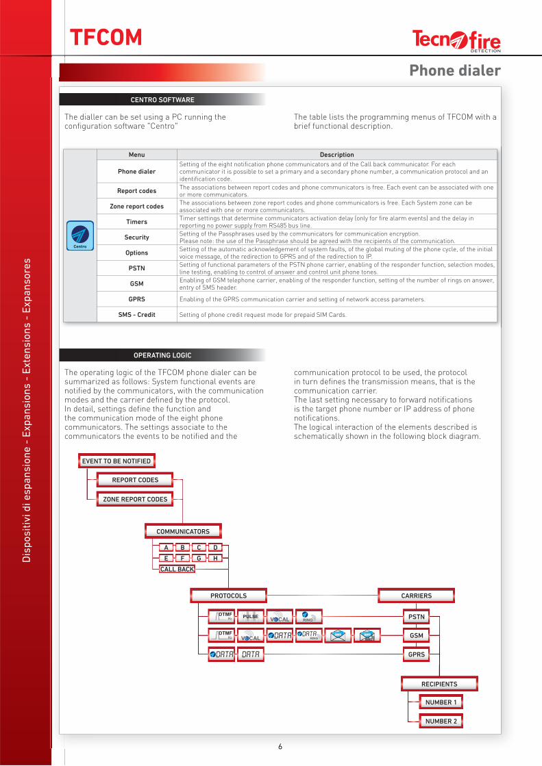
OPERATING LOGIC
The operating logic of the TFCOM phone dialer can be summarized as follows: System functional events are notified by the communicators, with the communication modes and the carrier defined by the protocol.In detail, settings define the function and the communication mode of the eight phone communicators. The settings associate to the communicators the events to be notified and the
communication protocol to be used, the protocol in turn defines the transmission means, that is the communication carrier. The last setting necessary to forward notifications is the target phone number or IP address of phone notifications.The logical interaction of the elements described is schematically shown in the following block diagram.
CENTRO SOFTWARE
The dialler can be set using a PC running the configuration software "Centro"
The table lists the programming menus of TFCOM with a brief functional description.
EVENT TO BE NOTIFIED
REPORT CODES
ZONE REPORT CODES
COMMUNICATORS
A
E
B
F
C
G
D
H
CALL BACK
PROTOCOLS CARRIERS
PSTN
GSM
GPRS
RECIPIENTS
NUMBER 1
NUMBER 2
Menu Description
Phone dialerSetting of the eight notifi cation phone communicators and of the Call back communicator. For each communicator it is possible to set a primary and a secondary phone number, a communication protocol and an identifi cation code.
Report codesThe associations between report codes and phone communicators is free. Each event can be associated with one or more communicators.
Zone report codesThe associations between zone report codes and phone communicators is free. Each System zone can be associated with one or more communicators.
TimersTimer settings that determine communicators activation delay (only for fi re alarm events) and the delay in reporting no power supply from RS485 bus line.
SecuritySetting of the Passphrases used by the communicators for communication encryption.Please note: the use of the Passphrase should be agreed with the recipients of the communication.
OptionsSetting of the automatic acknowledgement of system faults, of the global muting of the phone cycle, of the initial voice message, of the redirection to GPRS and of the redirection to IP.
PSTNSetting of functional parameters of the PSTN phone carrier, enabling of the responder function, selection modes, line testing, enabling to control of answer and control unit phone tones.
GSMEnabling of GSM telephone carrier, enabling of the responder function, setting of the number of rings on answer, entry of SMS header.
GPRS Enabling of the GPRS communication carrier and setting of network access parameters.
SMS - Credit Setting of phone credit request mode for prepaid SIM Cards.
TFCOM
Dis
po
sit
ivi
di
es
pa
ns
ion
e -
Ex
pa
ns
ion
s -
Ex
ten
sio
ns
- E
xp
an
so
res
7
Phone dialer
OPERATING PARAMETERS
The eight communicators operate independently according to the operating parameters set:Phone numbersPhone numbers no. 1 and no. 2 are the recipients of event notifications (for GPRS protocols in place of the number you can set the IP address). The first number is the primary recipient, the second number is called only if the communication to the first recipient fails. For the syntax of the IP addresses you can use two modes, address only or address and communications port:IP address - The IP address consists of 4 numeric fields, interspersed by a character, dot or dash, in this case the dialer uses the port set for the TECNOSERVER TECNOALARM Client channel. IP address and communication port - In this case a 5th numeric field that defines the port is appended to the 4 numeric fields of the IP address. The 5 fields must be separated by the dot or dash character.
ID (identification)Numeric code (max. 6 digits), with which the recipient (alarm reception centre) identifies the origin of the notification.If the ID is not set, the communicator sends the identification of the control unit.ProtocolCommunication mode of the notification. The communication protocol can be either audible or digital. The use of digital protocols should be agreed with the receiving reception center. See table of available protocols.
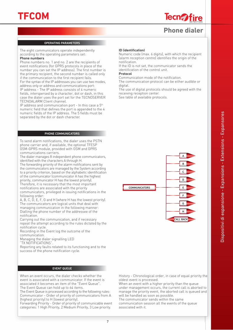
PHONE COMMUNICATORS
To send alarm notifications, the dialer uses the PSTN phone carrier and, if available, the optional TFESP GSM-GPRS module, provided with GSM and GPRS communications carriers.The dialer manages 8 independent phone communicators, identified with the characters A through H.The forwarding priority of the alarm notifications sent by the communicators are managed by the System according to a priority criterion, based on the alphabetic identification of the communicator (communicator A has the highest priority, communicator H has the lowest priority).Therefore, it is necessary that the most important notifications are associated with the priority communicators, privileged in issuing notifications in the following order:A, B, C, D, E, F, G and H (where H has the lowest priority).The communicators are logical units that deal with managing communication in the following manner:Dialling the phone number of the addressee of the notification.Carrying out the communication, and if necessary repeat the attempt according to the rules dictated by the notification cycle.Recording in the Event log the outcome of the communication.Managing the dialer signalling LED “TX NOTIFICATIONS”.Reporting any faults related to its functioning and to the success of the phone notification cycle.
EVENT QUEUE
When an event occurs, the dialer checks whether the event is associated with a communicator. If the event is associated it becomes an item of the "Event Queue". The Event Queue can hold up to 64 items. The Event Queue is processed according to the following rules:Communicator - Order of priority of communicators from A (highest priority) to H (lowest priority).Forwarding Priority - Order of priority of communicable event categories: 1 High Priority, 2 Medium Priority, 3 Low priority.
History - Chronological order, in case of equal priority the oldest event is processed.When an event with a higher priority than the queue under management occurs, the current call is aborted to manage the priority event, the aborted call is queued and will be handled as soon as possible.The communicator sends within the same communication session all the events of the queue associated with it.
COMMUNICATORS
H
CALL BACK
G
F
E
C
B
A
D
Dis
po
sit
ivi
di
es
pa
ns
ion
e -
Ex
pa
ns
ion
s -
Ex
ten
sio
ns
- E
xp
an
so
res
TFCOM
8
Phone dialer
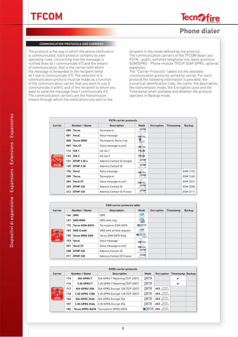
COMMUNICATION PROTOCOLS AND CARRIERS
The protocol is the way in which the phone notification is communicated. Each protocol contains its own operating rules, concerning how the message is notified (how do I communicate it?) and the means of communication, that is the carrier with which the message is forwarded to the recipient (what do I use to communicate it?). The selection of a communication protocol must be made as a function of the communication carrier that you want to use (I communicate it with!), and of the recipient to whom you want to send the message (how I communicate it!).The communication carriers are the transmission means through which the notifications are sent to the
recipient in the mode defined by the protocol.The communication carriers of the TFCOM dialer are:PSTN - public switched telephone line, basic provision.GSM/GPRS - Phone module TFESP GSM-GPRS, optional expansion.The "Carrier Protocols" tables list the available communication protocols sorted by carrier. For each protocol the following information is provided: the numerical identification code, the name, the description, the transmission mode, the Encryption used and the Timestamp when available and whether the protocol operates in Backup mode.
PSTN carrier protocols
Carrier Number / Name Description Mode Encryption Timestamp Backup
000 Tecno Tecnoalarm
001 Vocal Voice message
008 Tecno RING Tecnoalarm Tecno ring
009 Voc.CF Voice message w.conf.
114 SIA 1 fsk sia 1
122 SIA 2 fsk sia 2
131 DTMF C.ID s Ademco Contact ID (single)
139 DTMF C.ID Ademco Contact ID
196 Vocal Voice message GSM (193)
200 Tecno Tecnoalarm GSM (160)
204 Vocal CF Voice message w.conf GSM (201)
209 DTMF CID Ademco Contact ID GSM (208)
212 DTMF CID Ademco Contact ID France GSM (211)
GPRS carrier protocols
Carrier Number / Name Description Mode Encryption Timestamp Backup
115 SIA-GPRS-T SIA-GPRS-T Reporting [TCP-2007] ✔
116 C.ID-GPRS-T C.ID-GPRS-T Reporting [TCP-2007] ✔
117 SIA-GPRS128b SIA-GPRS Encrypt 128 [TCP-2007]
118 C.ID-GPRS 128b C.ID-GPRS Encrypt 128 [TCP-2007]
156 SIA-GPRS 256b SIA-GPRS Encrypt 256
157 C.ID-GPRS 256b C.ID-GPRS Encript 256
182 Tecno GPRS-DATA Tecnoalarm GPRS-DATA
GSM carrier protocols table
Carrier Number / Name Description Mode Encryption Timestamp Backup
166 SMS SMS
167 SMS RING SMS whit ring
175 Tecno GSM-DATA Tecnoalarm GSM-DATA
183 SMS Credit SMS whit airtime request
190 Tecno RING GSM Tecno GSM DATA Ring
193 Vocal Voice message
201 Vocal CF Voice message w.conf
208 DTMF CID Ademco Contact ID
211 DTMF CID Ademco Contact ID France
Dis
po
sit
ivi
di
es
pa
ns
ion
e -
Ex
pa
ns
ion
s -
Ex
ten
sio
ns
- E
xp
an
so
res
TFCOM
204 Voice messageVectorMode
333183698AT&T
GSM
333183698
1 2 34 5 67 8 9
* 0 #201 Voice messageVectorMode
Evento
Evento
182 Tecno GPRS-DATA
256.20.235.20.1001 N° tel.1 N° tel.1
196 Vocal
1 2 34 5 67 8 9
* 0 #
0115641897
122 fsk sia 1
333183698AT&T
GSM
N° tel.20115698745
N° tel.1
193 Vocal
1 2 34 5 67 8 9
* 0 #
011561589
N° tel.20116598788
1 2 34 5 67 8 9
* 0 #
N° tel.1
182 Tecno GPRS-DATA
160.10.242.18.1001 N° tel.1
N° tel.2 N° tel.2 N° tel.20223232323
VectorMode
VectorMode
VectorMode
VectorMode
VectorMode
9
Phone dialer
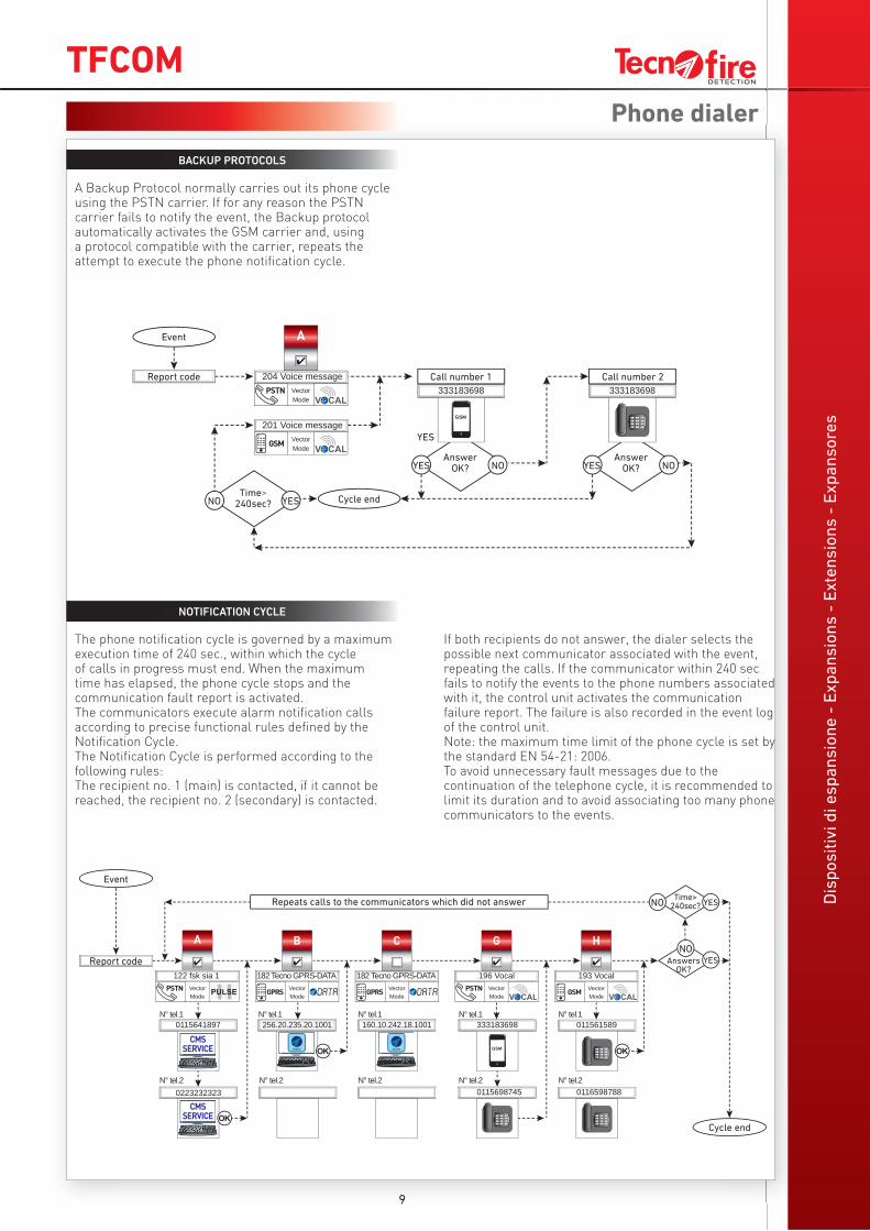
BACKUP PROTOCOLS
A Backup Protocol normally carries out its phone cycle using the PSTN carrier. If for any reason the PSTN carrier fails to notify the event, the Backup protocol automatically activates the GSM carrier and, using a protocol compatible with the carrier, repeats the attempt to execute the phone notification cycle.
NOTIFICATION CYCLE
The phone notification cycle is governed by a maximum execution time of 240 sec., within which the cycle of calls in progress must end. When the maximum time has elapsed, the phone cycle stops and the communication fault report is activated.The communicators execute alarm notification calls according to precise functional rules defined by the Notification Cycle.The Notification Cycle is performed according to the following rules:The recipient no. 1 (main) is contacted, if it cannot be reached, the recipient no. 2 (secondary) is contacted.
If both recipients do not answer, the dialer selects the possible next communicator associated with the event, repeating the calls. If the communicator within 240 sec fails to notify the events to the phone numbers associated with it, the control unit activates the communication failure report. The failure is also recorded in the event log of the control unit.Note: the maximum time limit of the phone cycle is set by the standard EN 54-21: 2006. To avoid unnecessary fault messages due to the continuation of the telephone cycle, it is recommended to limit its duration and to avoid associating too many phone communicators to the events.
Event
Report code
Time> 240sec? Cycle end
YES
NO YES
Answer OK?YES NO
Answer OK?YES NO
Call number 1 Call number 2
Event
Report code
Repeats calls to the communicators which did not answer Time>
240sec? YES
YES
NO
NO
Answers OK?
Cycle end
Dis
po
sit
ivi
di
es
pa
ns
ion
e -
Ex
pa
ns
ion
s -
Ex
ten
sio
ns
- E
xp
an
so
res
TFCOM
10
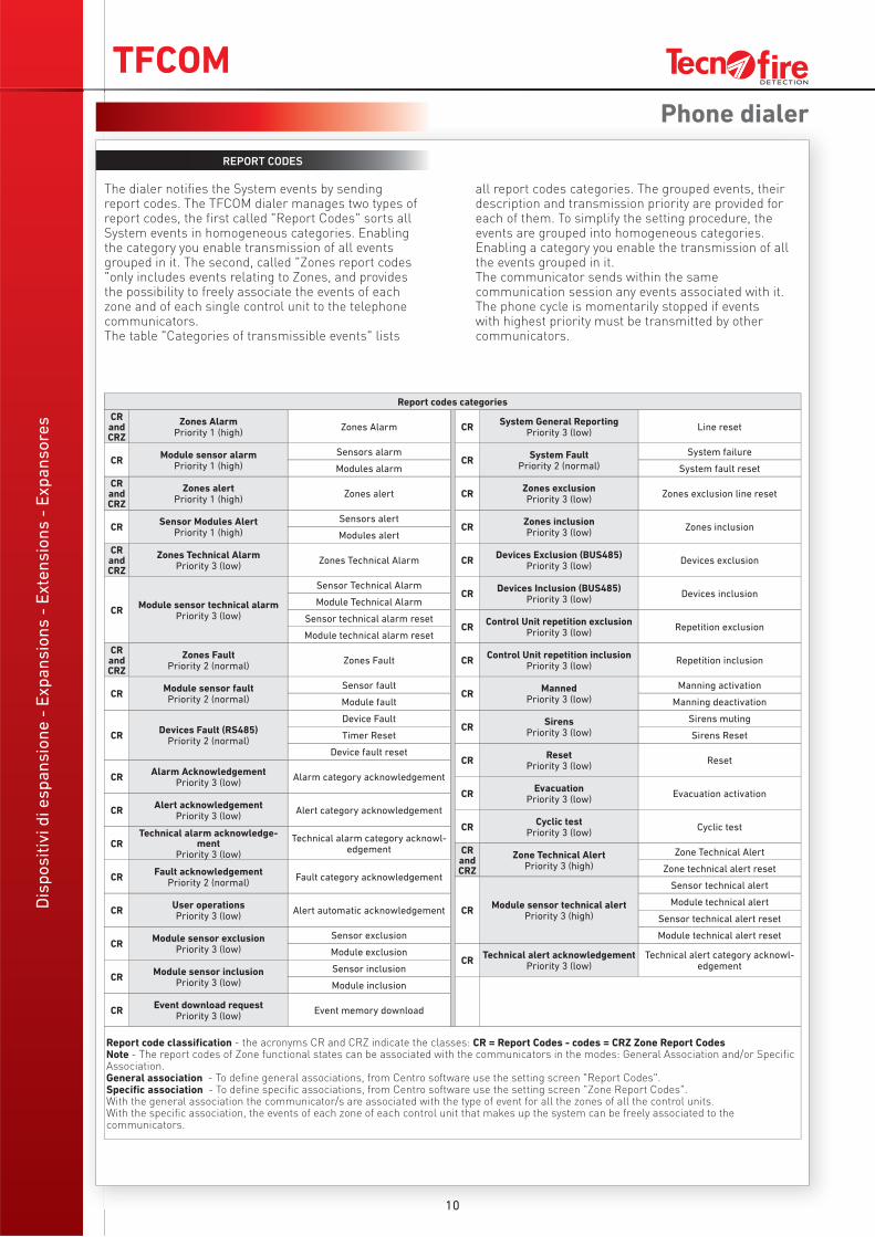
REPORT CODES
The dialer notifies the System events by sending report codes. The TFCOM dialer manages two types of report codes, the first called "Report Codes" sorts all System events in homogeneous categories. Enabling the category you enable transmission of all events grouped in it. The second, called "Zones report codes "only includes events relating to Zones, and provides the possibility to freely associate the events of each zone and of each single control unit to the telephone communicators.The table "Categories of transmissible events" lists
all report codes categories. The grouped events, their description and transmission priority are provided for each of them. To simplify the setting procedure, the events are grouped into homogeneous categories. Enabling a category you enable the transmission of all the events grouped in it.The communicator sends within the same communication session any events associated with it. The phone cycle is momentarily stopped if events with highest priority must be transmitted by other communicators.
Phone dialer
Report codes categories
CRandCRZ
Zones AlarmPriority 1 (high)
Zones Alarm CRSystem General Reporting
Priority 3 (low)Line reset
CRModule sensor alarm
Priority 1 (high)
Sensors alarmCR
System FaultPriority 2 (normal)
System failure
Modules alarm System fault reset
CRandCRZ
Zones alertPriority 1 (high)
Zones alert CRZones exclusionPriority 3 (low)
Zones exclusion line reset
CRSensor Modules Alert
Priority 1 (high)
Sensors alertCR
Zones inclusionPriority 3 (low)
Zones inclusionModules alert
CRandCRZ
Zones Technical AlarmPriority 3 (low)
Zones Technical Alarm CRDevices Exclusion (BUS485)
Priority 3 (low)Devices exclusion
CRModule sensor technical alarm
Priority 3 (low)
Sensor Technical AlarmCR
Devices Inclusion (BUS485)Priority 3 (low)
Devices inclusionModule Technical Alarm
Sensor technical alarm resetCR
Control Unit repetition exclusionPriority 3 (low)
Repetition exclusionModule technical alarm reset
CRandCRZ
Zones FaultPriority 2 (normal)
Zones Fault CRControl Unit repetition inclusion
Priority 3 (low)Repetition inclusion
CRModule sensor faultPriority 2 (normal)
Sensor faultCR
MannedPriority 3 (low)
Manning activation
Module fault Manning deactivation
CRDevices Fault (RS485)
Priority 2 (normal)
Device FaultCR
SirensPriority 3 (low)
Sirens muting
Timer Reset Sirens Reset
Device fault resetCR
ResetPriority 3 (low)
Reset
CRAlarm Acknowledgement
Priority 3 (low)Alarm category acknowledgement
CREvacuation
Priority 3 (low)Evacuation activation
CRAlert acknowledgement
Priority 3 (low)Alert category acknowledgement
CRCyclic test
Priority 3 (low)Cyclic test
CRTechnical alarm acknowledge-
mentPriority 3 (low)
Technical alarm category acknowl-edgement CR
andCRZ
Zone Technical AlertPriority 3 (high)
Zone Technical Alert
CRFault acknowledgement
Priority 2 (normal)Fault category acknowledgement
Zone technical alert reset
CRModule sensor technical alert
Priority 3 (high)
Sensor technical alert
CRUser operationsPriority 3 (low)
Alert automatic acknowledgementModule technical alert
Sensor technical alert reset
CRModule sensor exclusion
Priority 3 (low)
Sensor exclusion Module technical alert reset
Module exclusionCR
Technical alert acknowledgementPriority 3 (low)
Technical alert category acknowl-edgement
CRModule sensor inclusion
Priority 3 (low)
Sensor inclusion
Module inclusion
CREvent download request
Priority 3 (low)Event memory download
Report code classifi cation - the acronyms CR and CRZ indicate the classes: CR = Report Codes - codes = CRZ Zone Report CodesNote - The report codes of Zone functional states can be associated with the communicators in the modes: General Association and/or Specifi c Association.General association - To defi ne general associations, from Centro software use the setting screen "Report Codes".Specifi c association - To defi ne specifi c associations, from Centro software use the setting screen "Zone Report Codes".With the general association the communicator/s are associated with the type of event for all the zones of all the control units.With the specifi c association, the events of each zone of each control unit that makes up the system can be freely associated to the communicators.
Dis
po
sit
ivi
di
es
pa
ns
ion
e -
Ex
pa
ns
ion
s -
Ex
ten
sio
ns
- E
xp
an
so
res
TFCOM
PSTN disabilitatoPSTN disabled
GSM disabilitatoGSM disabled
VETTORE PSTNPSTN VECTOR
VETTORE GSMGSM VECTOR
ALIMENTAZIONEPOWER
Batteria bassaLow battery
Guasto BUS tacitatoBUS failure confirmed
Guasto alimentazionePower failure
BATTERIABATTERY
Guasto GSMGSM failure
Guasto PSTNPSTN failure
Guasto batteriaBattery failure
D E T E C T I O N
COLLOQUIO BUSCOMMUNICATION
TX NOTIFICHETX NOTIFICATIONS
Trasmissione in corsoTX active
Trasmissione OKTX OK
Guasto BUSBUS failure
1 2 34 5 67 8 9
* 0 #
AT&T
GSM
182 Tecno GPRS-DATA VectorMode
Evento
01123598753N° tel.1
0115641897
182 Tecno GPRS-DATA
AT&T
GSM
N° tel.1
N° tel.2N° tel.20223232323
VectorMode
1 2 34 5 67 8 9
* 0 #
VectorMode
196 Vocal
0114546897
Evento
01123598753N° tel.1
0115641897
182 Tecno GPRS-DATA
AT&T
GSM
N° tel.1
N° tel.2N° tel.20223232323
VectorMode
1 2 34 5 67 8 9
* 0 #
VectorMode
196 Vocal
0114546897
11
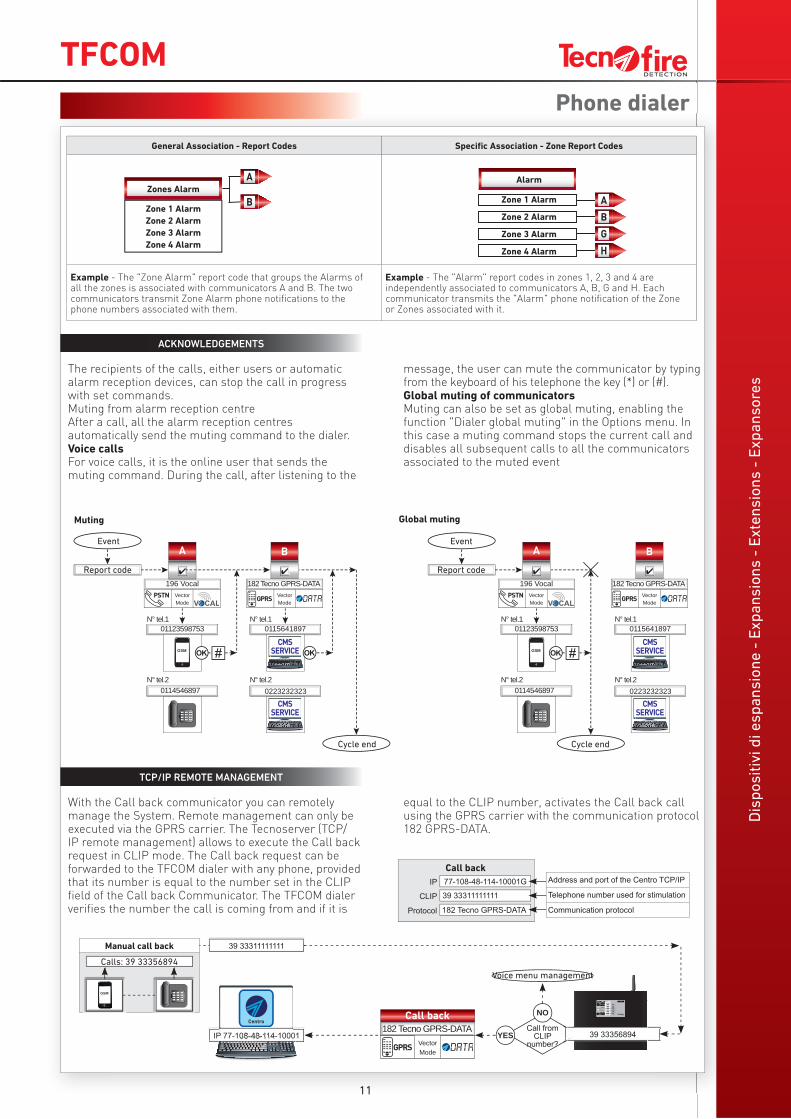
ACKNOWLEDGEMENTS
The recipients of the calls, either users or automatic alarm reception devices, can stop the call in progress with set commands.Muting from alarm reception centreAfter a call, all the alarm reception centres automatically send the muting command to the dialer.Voice callsFor voice calls, it is the online user that sends the muting command. During the call, after listening to the
message, the user can mute the communicator by typing from the keyboard of his telephone the key (*) or (#).Global muting of communicatorsMuting can also be set as global muting, enabling the function "Dialer global muting" in the Options menu. In this case a muting command stops the current call and disables all subsequent calls to all the communicators associated to the muted event
TCP/IP REMOTE MANAGEMENT
With the Call back communicator you can remotely manage the System. Remote management can only be executed via the GPRS carrier. The Tecnoserver (TCP/IP remote management) allows to execute the Call back request in CLIP mode. The Call back request can be forwarded to the TFCOM dialer with any phone, provided that its number is equal to the number set in the CLIP field of the Call back Communicator. The TFCOM dialer verifies the number the call is coming from and if it is
equal to the CLIP number, activates the Call back call using the GPRS carrier with the communication protocol 182 GPRS-DATA.
Phone dialer
General Association - Report Codes Specifi c Association - Zone Report Codes
Example - The "Zone Alarm" report code that groups the Alarms of all the zones is associated with communicators A and B. The two communicators transmit Zone Alarm phone notifi cations to the phone numbers associated with them.
Example - The "Alarm" report codes in zones 1, 2, 3 and 4 are independently associated to communicators A, B, G and H. Each communicator transmits the "Alarm" phone notifi cation of the Zone or Zones associated with it.
Zones Alarm
Zone 1 Alarm
Zone 2 Alarm
Zone 3 Alarm
Zone 4 Alarm
Alarm
Zone 1 Alarm
Zone 2 Alarm
Zone 3 Alarm
Zone 4 Alarm
Event
Report code
Cycle end
Event
Report code
Cycle end
Muting Global muting
Manual call back
IP 77-108-48-114-10001
Voice menu management
39 33311111111
NO
YESCall from
CLIP number?
Calls: 39 33356894
39 33356894
39 33311111111
77-108-48-114-10001G
182 Tecno GPRS-DATA
IP
CLIP
Protocol
Call backAddress and port of the Centro TCP/IP
Telephone number used for stimulation
Communication protocol
TFCOMD
isp
os
itiv
i d
i e
sp
an
sio
ne
- E
xp
an
sio
ns
- E
xte
ns
ion
s -
Ex
pa
ns
ore
s
TFESP GSM-GPRS
Phone dialer
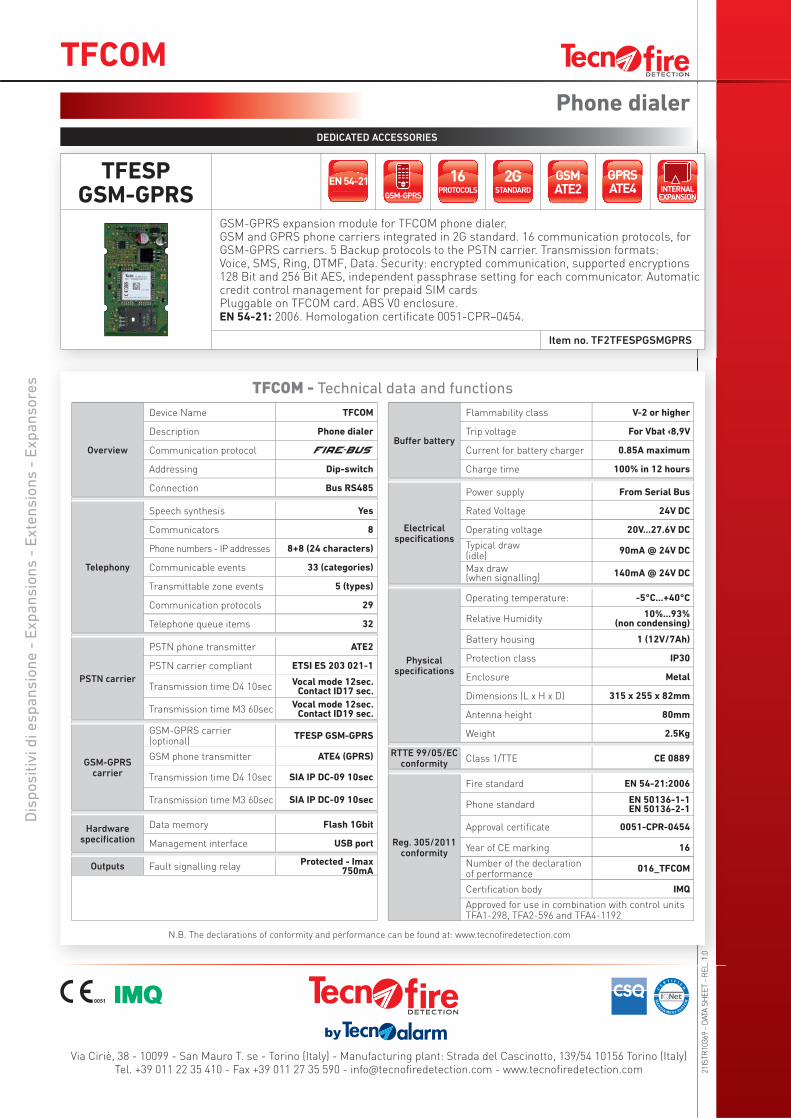
DEDICATED ACCESSORIES
TFCOM - Technical data and functions
N.B. The declarations of conformity and performance can be found at: www.tecnofiredetection.com
Item no. TF2TFESPGSMGPRS
Overview
Device Name TFCOM
Description Phone dialer
Communication protocol
Addressing Dip-switch
Connection Bus RS485
Telephony
Speech synthesis Yes
Communicators 8
Phone numbers - IP addresses 8+8 (24 characters)
Communicable events 33 (categories)
Transmittable zone events 5 (types)
Communication protocols 29
Telephone queue items 32
PSTN carrier
PSTN phone transmitter ATE2
PSTN carrier compliant ETSI ES 203 021-1
Transmission time D4 10secVocal mode 12sec.
Contact ID17 sec.
Transmission time M3 60secVocal mode 12sec.
Contact ID19 sec.
GSM-GPRS carrier
GSM-GPRS carrier (optional)
TFESP GSM-GPRS
GSM phone transmitter ATE4 (GPRS)
Transmission time D4 10sec SIA IP DC-09 10sec
Transmission time M3 60sec SIA IP DC-09 10sec
Hardware specifi cation
Data memory Flash 1Gbit
Management interface USB port
Outputs Fault signalling relayProtected - Imax
750mA
Buff er battery
Flammability class V-2 or higher
Trip voltage For Vbat ‹8,9V
Current for battery charger 0.85A maximum
Charge time 100% in 12 hours
Electrical specifi cations
Power supply From Serial Bus
Rated Voltage 24V DC
Operating voltage 20V...27.6V DC
Typical draw (idle)
90mA @ 24V DC
Max draw(when signalling)
140mA @ 24V DC
Physical specifi cations
Operating temperature: -5°C...+40°C
Relative Humidity10%...93%
(non condensing)
Battery housing 1 (12V/7Ah)
Protection class IP30
Enclosure Metal
Dimensions (L x H x D) 315 x 255 x 82mm
Antenna height 80mm
Weight 2.5Kg
RTTE 99/05/EC conformity
Class 1/TTE CE 0889
Reg. 305/2011 conformity
Fire standard EN 54-21:2006
Phone standardEN 50136-1-1EN 50136-2-1
Approval certifi cate 0051-CPR-0454
Year of CE marking 16
Number of the declaration of performance
016_TFCOM
Certifi cation body IMQ
Approved for use in combination with control units TFA1-298, TFA2-596 and TFA4-1192
GSM-GPRS expansion module for TFCOM phone dialer. GSM and GPRS phone carriers integrated in 2G standard. 16 communication protocols, for GSM-GPRS carriers. 5 Backup protocols to the PSTN carrier. Transmission formats: Voice, SMS, Ring, DTMF, Data. Security: encrypted communication, supported encryptions 128 Bit and 256 Bit AES, independent passphrase setting for each communicator. Automatic credit control management for prepaid SIM cards Pluggable on TFCOM card. ABS V0 enclosure.EN 54-21: 2006. Homologation certificate 0051-CPR–0454.
21IS
TR
10369 -
DATA
SH
EE
T -
RE
L. 1
.0
Via Ciriè, 38 - 10099 - San Mauro T. se - Torino (Italy) - Manufacturing plant: Strada del Cascinotto, 139/54 10156 Torino (Italy)Tel. +39 011 22 35 410 - Fax +39 011 27 35 590 - info@tecnofi redetection.com - www.tecnofi redetection.com