DPC2+ Rear Cover v3
190
Dukane Corporation • Ultrasonics Division • 2900 Dukane Drive • St. Charles, Illinois 60174 USA • TEL (630) 797–4900 • FAX (630) 797–4949 Dukane Part No. 403–551-03 www.dukcorp.com/us ISO 9001:2000 Dukane products are manufactured in ISO registered facilities User’s Manual 04 05 06 07 08 09 10 11 12 13 14 15 16 17 18 19 20 21 22 23 24 25 04 05 06 07 08 09 10 11 12 13 14 15 16 17 18 19 20 21 22 23 24 25 04 05 06 07 08 09 10 11 12 13 14 15 16 17 18 19 20 21 22 23 24 25 04 05 06 07 08 09 10 11 12 13 14 15 16 17 18 19 20 21 22 23 24 25
Transcript of DPC2+ Rear Cover v3

Dukane Corporation • Ultrasonics Division • 2900 Dukane Drive • St. Charles, Illinois 60174 USA • TEL (630) 797–4900 • FAX (630) 797–4949
Dukane Part No. 403–551-03
www.dukcorp.com/usISO 9001:2000 Dukane products are manufacturedin ISO registered facilities
User’s Manual
0405
0607
0809
1011
1213
1415
1617
1819
2021
2223
2425
0405
0607
0809
1011
1213
1415
1617
1819
2021
2223
2425
0405
0607
0809
1011
1213
1415
1617
1819
2021
2223
2425
0405
0607
0809
1011
1213
1415
1617
1819
2021
2223
2425
Copyright © 2002—2005 Dukane CorporationUltrasonics Division2900 Dukane DriveSt. Charles, IL 60174 USA
Notice of Rights:All rights reserved. No part of this manual including the inte-rior design, cover design and icons may be reproduced, trans-mitted or utilized in any form or by any means, electronic,mechanical, photocopying, recording, or by any informationstorage and retrieval system, without written permission fromDukane Corporation.
Notice of Liability:The information contained is this manual is distributed on an“As is” basis, without warranty. While every precaution hasbeen taken in the preparation of this manual, Dukane Corpo-ration shall not have any liability to any person or entity withrespect to any liability, loss, or damaged caused or alleged tobe caused directly or indirectly by the instructions containedin this manual, or by the hardware and software products de-scribed herein.
Printed in the United States of America.
Dukane Part Number: 403–551–03
PRINTED ON RECYCLED PAPER
Dukane ultrasonic equipment is manufactured under one or more of the followingU.S. Patents:3,780,926 3,825,481 4,131,505 4,277,710 5,798,599 and 5,880,580.
DPC™ is a trademark of Dukane Corporation
DPC™ II Plus – User’s Manual
ii Dukane Manual Part No. 403-551-03

Table of Contents
Dukane Manual Part No. 403-551-03 iii
DPC II Plus Manual Revision HistoryRevision RevisionNumber Contents Date
–00 Original release 2002–Nov–13
–01 Modify Table 5—V on page 48 (Pin 9 is +22V DC) 2004–May–14Update telephone numbers and emails in Section 14Revise ISO 9001 Certification to ISO 9001:2000Clarify AFTERBURST option bypass on page 73 and 80.
–02 Emergency Stop Switch Interface Diagram on page 25 2005–Jan–11DPC II Plus Software now at version 1.50New consolidated warranty
–03 Updated power requirements in Table 15—I 2005–Apr–22Update Figure 15–2 Interpreting DPC II Plus Model No.Add Figure 5–10 Press Board Cycle Activation Jumper Block on p. 50Update TOC, Appendix A and Index
Dukane Corporation • • Ultrasonics Division

iv Dukane Manual Part No. 403-551-03
DPC II Plus – User’s Manual
This page intentionally left blank

Table of Contents
Dukane Manual Part No. 403-551-03 v
TABLE OF CONTENTS
Section 1 – Introduction........................................................... 1Before Operating ................................................................................... 3
Read The Manual First ................................................................................... 3Caution and Warnings................................................................................... 3Drawings Labels ............................................................................................. 3
Manual Organization............................................................................. 4DPC–II Plus Overview.............................................................................. 6Key DPC–II Plus Features ........................................................................ 7
Section 2 – Safety Tips.............................................................. 9Health & Safety Tips ............................................................................. 11
Plastics Health Notice .................................................................................. 12Electrical Grounding Safety ........................................................................ 12
RFI Considerations ................................................................................ 13
Section 3 – Unpacking & Installation .................................... 15Shipping Carton Contents ................................................................... 17DPC Placement ..................................................................................... 17
Benchtop ...................................................................................................... 17Rack Mounting............................................................................................. 18
Rear Panel Overview ............................................................................ 19Ground the System............................................................................... 19Connect the Cables .............................................................................. 20
Hand Probe System ...................................................................................... 20Automated Probe System ........................................................................... 20Multiple Probe System ................................................................................ 22Automated Thruster System ....................................................................... 23Dukane Press System ................................................................................... 24Emergency Stop Switch Interface ............................................................... 25Rear Electrical Power Switch ....................................................................... 25
Section 4 – Controls & Displays.............................................. 27Front Panel Layout ............................................................................... 29AC Power .............................................................................................. 30Generator Status Section ..................................................................... 30
Generator Control Keys ............................................................................... 30System Status Display .................................................................................. 31System Power Output Display ..................................................................... 32
Process Control ..................................................................................... 33Process Control Keys .................................................................................... 33Menu Display ............................................................................................... 35

vi Dukane Manual Part No. 403-551-03
DPC II Plus – User’s Manual
Section 5 – Rear Connectors .................................................. 37Rear Panel Layout ................................................................................ 39System Input Connector....................................................................... 40System Output Connector ................................................................... 42Remote Amplitude Control ................................................................. 46Power Output Module Option ............................................................ 47Press Control Module Option .............................................................. 48Multi–Probe Module Options .............................................................. 50Jumper Block Options .......................................................................... 51
Card Slot and Jumper Block Locations ....................................................... 52Jumper Block Details ................................................................................... 53
Section 6 – Menu Structure ................................................... 55Process Setup ........................................................................................ 57Process Control ..................................................................................... 58Process Limits ........................................................................................ 60Utilities .................................................................................................. 61
Section 7 – Process Setup Menu ............................................ 63Hand Probe ........................................................................................... 65
Untimed Hand Probe ................................................................................... 66Timed Hand Probe ....................................................................................... 66Timed Hand Probe – Energy........................................................................ 67
MPC Probe ............................................................................................ 68Auto Stop Option ........................................................................................ 68Untimed MPC Probe – Probe Delay ............................................................ 68Weld Method – Time ................................................................................... 69Weld Method – Energy................................................................................ 70Weld Method – Ground Detect .................................................................. 70
Auto Probe ........................................................................................... 71Auto Stop Option ........................................................................................ 72Untimed Auto Probe – Delay ...................................................................... 73Timed Auto Probe – Weld Method............................................................. 73HoldTime ...................................................................................................... 73Afterburst ..................................................................................................... 73
Press Mode ........................................................................................... 75Initiate Mode ............................................................................................... 76Auto Stop ..................................................................................................... 76Head Up On Auto Stop ............................................................................... 76Trigger Type.................................................................................................. 76Single/Dual Pressure Mode ......................................................................... 76

Table of Contents
Dukane Manual Part No. 403-551-03 vii
Press Mode Example ............................................................................ 77Hot Keys ................................................................................................ 81Process Control Recap .......................................................................... 82
Section 8– Process Limits Menu ............................................. 87Process Limits Menu ............................................................................. 89Limit Definition .................................................................................... 90Suspect and Bad Limits ........................................................................ 90Process Limits ........................................................................................ 90
Single Pressure Mode .................................................................................. 91Dual Pressure Mode ..................................................................................... 92
Section 9 – Utilities Menu ...................................................... 95Setup Utilities ....................................................................................... 97
Select Setup .................................................................................................. 98Copy A Setup................................................................................................ 99Erase Setups ................................................................................................. 99
Part Count........................................................................................... 100Reset Part Count ........................................................................................ 100Count Suspect/Bad Parts ............................................................................100Preset Part Count ....................................................................................... 101
Status Outputs .................................................................................... 101Cycle Press Off Line ............................................................................ 101
Section 11 – Probes/Probe Stacks ........................................ 103The Ultrasonic Probe .......................................................................... 105
Theory of Operation .................................................................................. 105Probe Configuration .................................................................................. 105Ultrasonic Horn .......................................................................................... 106Booster .......................................................................................................106
Stack Assembly ................................................................................... 107Installing Replaceable Tips ........................................................................ 107Mounting Stud to Horn/Booster ............................................................... 108Horn to Booster ......................................................................................... 109Booster to Probe ........................................................................................ 109Horn to Probe ............................................................................................ 109
Torque Unit Conversion Chart ........................................................... 110Stack Disassembly ............................................................................... 111Booster Notes ..................................................................................... 114Stack Mounting .................................................................................. 115

viii Dukane Manual Part No. 403-551-03
DPC II Plus – User’s Manual
Section 11 – DPC Checkout .................................................. 117Startup and Self–Test ......................................................................... 119System Test ......................................................................................... 120Probe Operation................................................................................. 121Stopping the Weld Cycle ................................................................... 121
Manual Systems ......................................................................................... 121Automated System .................................................................................... 121End of Day .................................................................................................. 121
Section 12 – Troubleshooting .............................................. 123No Ultrasonic Output ......................................................................... 125
Probe ..........................................................................................................125Cable ........................................................................................................... 125Generator ...................................................................................................126Operate Input ............................................................................................ 126
Generator Faults................................................................................. 127OVERLOAD Indicator ................................................................................. 127OVERTEMP Indicator ................................................................................. 127FAULT Indicator .......................................................................................... 127
Generator Errors................................................................................. 128INPUT TEST Indicator ................................................................................. 128TEST Control Key........................................................................................ 128
Troubleshooting Flowchart ............................................................... 129Error Messages ................................................................................... 131
Section 13 – Care & Maintenance ....................................... 133Front Panel ......................................................................................... 135Rear Panel ........................................................................................... 135Chasis .................................................................................................. 135Stack Surfaces ..................................................................................... 136
Stack Maintenance .................................................................................... 136Stack Inspection ......................................................................................... 136Even Contact .............................................................................................. 136Uneven Contact ......................................................................................... 136Crowning .................................................................................................... 137Center Depression...................................................................................... 137Corrosion .................................................................................................... 137
Probe Reconditioning ........................................................................ 138Overview .................................................................................................... 138Machining the Mating Surfaces ................................................................ 138Manual Resurfacing ................................................................................... 138

Table of Contents
Dukane Manual Part No. 403-551-03 ix
Section 14 – Contacting Dukane ......................................... 141Ultrasonics Division Main Office ....................................................... 143Email Addresses .................................................................................. 144Telephone Extensions ........................................................................ 144
Section 15 – Specifications ................................................... 145Regulatory Compliance...................................................................... 147
Federal Communications Commission...................................................... 147CE Marking (Conformité Europeéne) ....................................................... 147
Dimensions ......................................................................................... 148Operating Enviornment ..................................................................... 148Power Requirements .......................................................................... 149Interpreting The DPC Model Number ............................................... 150
Section 16 – Warranty .......................................................... 151Domestic warranty ............................................................................. 153International Warranty ...................................................................... 154
Appendix A - List of Figures ................................................ 155
Appendix B - List of Tables .................................................. 159
Appendix C - User Supplied Circuitry .................................. 161Manual Switch Circuit ........................................................................ 163Automation Switch Circuits ............................................................... 164Isolated Automation Controls ........................................................... 165
Current Sink ............................................................................................... 166Current Source ........................................................................................... 167
Index ..................................................................................... 169

x Dukane Manual Part No. 403-551-03
DPC II Plus – User’s Manual
This page intentionally left blank

1Dukane Manual Part No. 403–551–03
Section 1 – Introduction
Before Operating ............................................ 3Read The Manual First ............................................3
Caution and Warnings ...........................................3
Drawings Labels .....................................................3
Manual Organization ...................................... 4DPC–II Plus Overview ...................................... 6Key DPC–II Plus Features ................................. 7
Introduction• General Information
• Manual Organization
• DPC–II Plus Overview
• Key DPC–II Plus Features
Dukane Corporation • • Ultrasonics Division
SECTION 1

2 Dukane Manual Part No. 403–551–03
Dynamic Process Controller DPC™ II Plus – User’s Manual
This page intentionally left blank
3Dukane Manual Part No. 403–551–03
Section 1 – Introduction
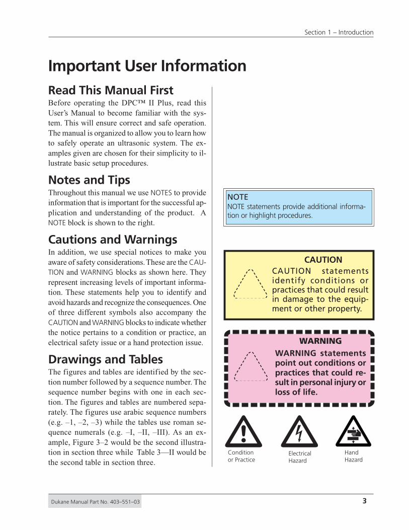
Important User InformationRead This Manual FirstBefore operating the DPC™ II Plus, read thisUser’s Manual to become familiar with the sys-tem. This will ensure correct and safe operation.The manual is organized to allow you to learn howto safely operate an ultrasonic system. The ex-amples given are chosen for their simplicity to il-lustrate basic setup procedures.
Notes and TipsThroughout this manual we use NOTES to provideinformation that is important for the successful ap-plication and understanding of the product. ANOTE block is shown to the right.
Cautions and WarningsIn addition, we use special notices to make youaware of safety considerations. These are the CAU-TION and WARNING blocks as shown here. Theyrepresent increasing levels of important informa-tion. These statements help you to identify andavoid hazards and recognize the consequences. Oneof three different symbols also accompany theCAUTION and WARNING blocks to indicate whetherthe notice pertains to a condition or practice, anelectrical safety issue or a hand protection issue.
Drawings and TablesThe figures and tables are identified by the sec-tion number followed by a sequence number. Thesequence number begins with one in each sec-tion. The figures and tables are numbered sepa-rately. The figures use arabic sequence numbers(e.g. –1, –2, –3) while the tables use roman se-quence numerals (e.g. –I, –II, –III). As an ex-ample, Figure 3–2 would be the second illustra-tion in section three while Table 3—II would bethe second table in section three.
Conditionor Practice
ElectricalHazard
HandHazard
CAUTIONCAUTION statementsidentify conditions orpractices that could resultin damage to the equip-ment or other property.
WARNINGWARNING statementspoint out conditions orpractices that could re-sult in personal injury orloss of life.
NOTENOTE statements provide additional informa-tion or highlight procedures.
� �

4 Dukane Manual Part No. 403–551–03
Dynamic Process Controller DPC™ II Plus – User’s Manual
Section 1 – Introduction describes the manual organizationand the key features of the Dukane DPCTM (Dy-namic Process Controller) II Plus Generator.
Section 2 – Safety discusses OSHA regulations and safetyconsiderations.
Section 3 – Unpacking and Installation explains the DPC IIPlus placement and setup. It also shows the cableconnections for quick–start operation.
Section 4 – Controls describes the function of the frontpanel controls, menu keys and status display.
Section 5 – Connectors gives the function, pinout and sig-nal description of the rear panel connectorson the DPC II Plus. Operation of the optionalmodules is described in detail. The internaljumper blocks to control process automationare also identified.
Section 6 – Process Setup describes the overall menu or-ganization of the DPC–II Plus, the setup andoperate modes and gives a brief summary of thethree main menus.
Section 7 – Process Control Menu describes the HandProbe, Timed Auto, MPC and Press modemenus and the Weld Methods. It also coversthe user interface configuration and param-eter values.
Section 8 – Limit Definition Menu describes the SuspectLimit and Bad Limit menus in detail.
Section 9 – Utilities Menu describes the Setup File Utilities,Part Count and Status Output menus in detail.
Section 10 –Hand Probe and Stack Assembly describes theassembly and mounting of both hand probes andprobe stack assemblies.
Section 11 –System Checkout describes basic systemtests to ensure that the DPC II Plus is func-tioning properly.
Manual Organization

5Dukane Manual Part No. 403–551–03
Section 1 – Introduction
Section 12 –Troubleshooting provides helpful tips on solv-ing the most common problems.
Section 13 –Maintenance lists a schedule of suggested pre-ventive maintenance items.
Section 14 –Contacting Dukane provides information oncontacting or obtaining support from your Du-kane Ultrasonics team.
Section 15 –Specifications lists the DPC–II Plus dimen-sions, power and space requirements. It alsointerprets the model number coding.
Section 16 –Warranty contains a copy of our equipmentwarranty and tooling warranty.
Appendices
A – List of Figures.
B – List of Tables.
C – Sample Circuitry for user supplied automation.
Index

6 Dukane Manual Part No. 403–551–03
Dynamic Process Controller DPC™ II Plus – User’s Manual
DPC II Plus OverviewThe DPC™ II Plus is the newest model in Dukane’s Dy-namic Process Controller product family. This system willaccept a wide variety of optional modules and is designedfor use with ultrasonic presses or applications that re-quire the use of hand probes or thruster systems.
The DPC II Plus provides basic system control inputsand system monitor and status outputs. This makes theDPC II Plus ideal for automated control systems. Signalconditioning and electrical isolation are also provided.
Like other DPC models, the II Plus includes the sameinternal ultrasonic generator circuitry and features. Op-tional modules are available to enhance the DPC’s abil-ity to meet a wide variety of process requirements. Themost common combination includes the Timer boardand a Press control board. Other options include anRemote Amplitude control, a Power Signal module forWeld–by–Energy requirements and up to two Multi–Probe controller modules for driving multiple probe sys-tems. In most cases, DPC II Plus systems in the fieldcan be upgraded on-site if they already have the stan-dard Timer board.
Like the other DPC models, all II Plus units (except thehighest power models) feature a universal power sup-ply with dual line–voltage input 1. In addition, the equip-ment is designed and tested to comply with the FCC andCE regulations that apply to this product. 1 See Table 15—I

7Dukane Manual Part No. 403–551–03
Section 1 – Introduction
DPC II Plus Key Features• Timer Board option provides weld and hold
time control and stores up to eight setup files.
• Press Board option provides control for aDukane ultrasonic press and thruster.
• Multi–Point Control Module option permitsone DPC to handle up to eight probes in anautomation environment (DPC II Plus or DPC II).
• Plug and Weld system recognizes when modulesare added or removed from the system
• Process Control Menu automaticallyreconfigures the user interface to conform to themodules or hand probes currently installed.
• 4–Line LCD Display gives the completeparameter setting to speedup the setup process.
• System Connections are provided forautomation equipment to monitor and controlthe ultrasonic welding process.
• Modular Design simplif ies upgrades andincreases flexibility as your applicationrequirements change.
• Flow Through Cooling Tunnel isthermostatically controlled to reduce thermalgradients and increase component life.
• Pulse Width Modulation is Dukane’s patentedcircuitry that allows the DPC power supply toeff iciently control the voltage sent to thetransducer in the acoustic stack.
• Linear Ramp Softstart circuitry is providedallowing the acoustic stack to be brought tooperating amplitude smoothly, minimizing thestartup shock stress.
• Auto-Trac Tuning automatically tracks theresonant frequency of the acoustic stack (horn,booster, transducer), and adjusts the generatoroutput frequency to match it. 2
(continued on next page)
2 Within specified ranges
8 Dukane Manual Part No. 403–551–03
Dynamic Process Controller DPC™ II Plus – User’s Manual
• Dual Line–Voltage 1 Universal Power Supplymeans that the DPC II will operate worldwide.Auto-Ranging means that adjustments by theoperator related to power input are unnecessary.
• Line Voltage Regulation automaticallymaintains a constant output regardless of linevoltage deviation. 2
• Load Regulation provides constant amplitudeautomatically up to the rated overload power level.
• Electronic Overload protection preventcomponent failure.
• High Performance fan and heatsink extendcomponent life.
• CE Certification means that the DPC II Plusmeets the required European standards to be soldand used in Europe.
• ISO 9001 Certification means that the DPC IIPlus is manufactured to very high qualitystandards and assures you of Dukane’scommitment to being a quality vendor and its goalof continuous improvement.
* Within specified ranges

9Dukane Manual Part No. 403–551–03
Section 1 – Introduction
Safety Tips• Health & Safety
• RFI Considerations
Dukane Corporation • • Ultrasonics Division
SECTION 2
Health & Safety Tips...................................... 11Plastics Health Notice ...........................................12
Electrical Grounding Safety ..................................12
RFI Considerations ........................................ 13
�

10 Dukane Manual Part No. 403–551–03
Dynamic Process Controller DPC™ II Plus – User’s Manual
This page intentionally left blank

11Dukane Manual Part No. 403–551–03
Section 2 – Safety Tips
Health and Safety TipsPlease observe these health and safety recommen-dations for safe, efficient, and injury-free opera-tion of your equipment. In this manual, the termsystem refers to a complete group of componentsassociated with the welding of plastic or metalparts, also known as an ultrasonic assembly sys-tem. A typical system consists of a generator and/or ultrasonic process controller, start and stopswitches, power controls, connecting cables, andthe probe assembly which includes the transducer,booster, horn and replaceable horn tip.
Proper Installation – Operate system componentsonly after they are properly installed and checked.
No Unauthorized Modifications – Do not modifyyour system in any way unless authorized to do soby Dukane Corporation. Unauthorized modifica-tions may cause injury to the operator and/or equip-ment damage. In addition, unauthorized modifi-cations will void the equipment warranty.
Keep the Cover On – Do not remove the equip-ment cover unless specifically directed to do so byDukane Corporation. The generator produces haz-ardous electrical voltages which could cause in-jury.
Grounded Electrical Power – Operate this equip-ment only with a properly grounded electrical con-nection. (See Electrical Safety Grounding Instruc-tions on the next page.)
Comply with Regulations – You may be requiredto add accessories to bring the system into com-pliance with applicable OSHA regulations.
CAUTIONParts being joined ultra-sonically sometimesvibrate at audible fre-quencies. Wear earprotection to reduce an-noying or uncomfortablesounds. In addition,sound absorbing materi-als, enclosures or sounddeflectors may be in-stalled to reduce thenoise level.
IMPORTANTNever operate the DPC IIPlus with the cover off.This is an unsafe practiceand may cause injury.�

12 Dukane Manual Part No. 403–551–03
Dynamic Process Controller DPC™ II Plus – User’s Manual
Plastics Health NoticeBefore using any Dukane ultrasonic welding sys-tem, be sure you are familiar with OSHA regula-tions from the U.S. Department of Labor about theparticular type of plastic(s) you are using.
When plastic materials are being processed, theymay emit fumes and/or gases that could be haz-ardous.
Make sure there is proper ventilation wheneverthese plastics are processed.
Electrical Safety GroundingInstructionsFor safety, the power cords used on all Dukaneproducts have a three-prong, grounding-type plug.
Approved 2 pole, 3 wire groundingreceptacle BRYANT No. 5621 orequivalent to NEMA 5–15R or 5–20R
Approved 2 pole, 3 wire groundingreceptacle HUBBELL No. 5652 orequivalent to NEMA 6–15R or 6–20R
Figure 2-2 Example of 220 Volt, Grounded,3-Prong Receptacle
Figure 2-1 Example of 120 Volt, Grounded,3-Prong Receptacle
CAUTIONIf there is any questionabout the grounding ofyour receptacle, have itchecked by a qualifiedelectrician. Do not cutoff the power cordgrounding prong, or al-ter the plug in any way.If an extension cord isneeded, use a three-wire cord that is in goodcondition. The cordshould have an ad-equate power rating todo the job safely. It mustbe plugged into agrounded receptacle.Do not use a two-wireextension cord with thisproduct.
�
�
CAUTIONIf you must have a two-prong electrical recep-tacle, we stronglyrecommend that you re-place it with a properlygrounded three-prongtype. Have a qualifiedelectrician replace it fol-lowing the National Elec-tric Code and any localcodes and ordinancesthat apply.See Figures 2-1 and 2-2.

13Dukane Manual Part No. 403–551–03
Section 2 – Safety Tips
The power cable normally provided for interna-tional use is compatible with many power outlets(refer to Figure 2-3.) However, if your applica-tion requires another type of cable, check withthe local Dukane products representative, and fol-low local regulations concerning proper wiringand grounding.
RFI ConsiderationsIn addition to the safety considerations, propergrounding at the generator power cord is essen-tial for the effective suppression of RFI (RadioFrequency Interference). Every DPC contains aRFI filter which blocks noise on the AC powerline from entering the DPC control circuitry. Thisfilter also prevents ultrasonic RFI from being fedback into the AC power line. In order for the RFIfilter to operate properly, it is necessary to ad-equately ground the DPC. Run an additionalgrounding wire from the rear grounding connec-tion (see Figure 2-4) to the nearest grounded metalpipe or equivalent earth ground by means of aground clamp. Use at least an 14 AWG** wirefor the connection to the DPC chassis. Strandedis more flexible and easier to work with than solidwire. However if you use stranded wire, crimpspade lugs on the end to ensure a good connection.If you have a color choice, green is the commonlyaccepted color for an electrical ground connection.
If you have connected the DPC to a Press and/orThruster, use a star † connection from the earthground to the DPC and Press as illustrated inFigure 2–5.
** 14 AWG wire has a diameter of 1.63mm or 0.064"
† Run seperate ground wires from each piece ofequipment to the earth ground. See the appropri-ate schematic diagram in Figures 3–4 thru 3–8.
ToGround
14 AWG Wire
Grounding Contacts
Typical Outlet
AC Power Cable (Provided)
O
I
10 – 24 x 1/2" threaded stud
14 AWG to Earth Ground
Figure 2-4 DPCGrounding Arrangement
Figure 2-3 International 220/240V Grounding
Figure 2-5 Press Grounding Arrangement

14 Dukane Manual Part No. 403–551–03
Dynamic Process Controller DPC™ II Plus – User’s Manual
This page intentionally left blank
15Dukane Manual Part No. 403–551–03
Section 2 – Safety Tips
Unpacking & Installation
Dukane Corporation • • Ultrasonics Division
SECTION 3
Shipping Carton Contents ............................ 17DPC Placement ............................................. 17
Benchtop .............................................................17
Rack Mounting ....................................................18
Rear Panel Overview ..................................... 19Ground the System ....................................... 19Connect the Cables ...................................... 20
Hand Probe System ..............................................20
Automated Probe System .....................................20
Multiple Probe System..........................................22
Automated Thruster System .................................23
Dukane Press System ............................................24
Emergency Stop Switch Interface .........................25
Rear Electrical Power Switch .................................25
• Unpacking the DPC
• Placement of the DPC
• Rear Panel Overview
• Grounding the System
• Connecting the Cables

16 Dukane Manual Part No. 403–551–03
Dynamic Process Controller DPC™ II Plus – User’s Manual
This page intentionally left blank

17Dukane Manual Part No. 403–551–03
Section 3 – Unpacking and Installation
Shipping Contents
Carefully open the shipping container, and makesure it contains the items shown in Table 3–I. In-spect the DPC for damage. Report any damageimmediately to Dukane Ultrasonics Support/Ser-vice.
DPC PlacementPlacement of the DPC depends on whether it is abenchtop or rack-mounted configuration
BenchtopPlace the DPC on a flat surface with its front paneleasily accessible. Make certain the placement andcabling do not interfere with the assembly opera-tion.Allow 5 inches (13 cm) at the rear of the DPC forcable clearance. Allow 2 inches (5 cm) of spaceon either side of the DPC for air circulation. Re-fer to the illustration in Figure 3-1.
Quantity Item Part Number
DPC II Plus1
1
**
DPC II Plus User's Manual 403–551–02
** DPC Part Number depends upon Frequency and Power Rating
AC power cord and cables as specified. See your Packing List.Compare with Table 3—II on page 21.
2200
2200
STATUS
FAULT
ON LINE
INPUT TEST
OVERTEMP
OVERLOAD
OFF LINE
0 20 40 60 80 100PERCENTAGE OF AVAILABLE POWERPERCENTAGE OF AVAILABLE POWER
SYSTEM POWER OUTPUT
ONLINE
ENTER CANCEL
MODE
ENTERWELD
P1
AMP.
ADJUST
WELD
P2
GEN
INFO.+
–
TESTOFFLINE
Dynamic Process ControllerDynamic Process Controller DPC II DPC II PLUSPLUS
Allow 5 inches (13 cm) space for cables behind the DPC
Allow space for ventilation,
2 inches (5 cm) on each side.
Exhaust Air fromFlow–Thru Cooling Tunnel
Intake Vent for Thermostatically Controlled Fan
CAUTIONAllow space for air venti-lation around the DPC IIPlus chassis, the air intakeand exhaust. The fan drawsin fresh air to cool the in-ternal components, reducethermal gradients andincrease component life.When viewed from thefront, the fresh air intake ison the right and the hot airexhaust is on the left side.If excessive dust accumulatesin the slots, wipe or vacuumthem clean. Do not use com-pressed air as this may forcethe dust inside the chassis.
�
Table 3—I Contents of DPC II Plus Shipping Container
Figure 3-1 Installing a Benchtop DPC

18 Dukane Manual Part No. 403–551–03
Dynamic Process Controller DPC™ II Plus – User’s Manual
Figure 3-2 shows the use of a bracket kit inmounting a DPC to a 19-inch equipment rack.(Contact Ultrasonic Sales at Dukane, and requestPart Number US-1155.) The DPC illustratedhas the standard, angled front panel of impact-resistant ABS plastic.
Rack Mounting22
0022
00 STATUS
FAULT
ON LINE
INPUT TEST
OVERTEMP
OVERLOAD
OFF LINE
0 20 40 60 80 100PERCENTAGE OF AVAILABLE POWERPERCENTAGE OF AVAILABLE POWER
SYSTEM POWER OUTPUT
ONLINE
WELDP1
WELDP1
AMP.ADJUST
GEN.OINFO.
CANCELENTER
WELDP1
MODE
+
–
TEST OFFLINEDynamic Process ControllerDynamic Process Controller DDPC II PlusPC II Plus
Approximate17.35 inches (44 cm)
Approximate
22.25 in
(57 cm)
19 inches (48 cm)
Allow 5 inches (13 cm) of space behind the DPC for cables
CAUTIONAllow space for air venti-lation around the DPC IIPlus chassis, air intake andexhaust. The fan draws infresh air to cool the inter-nal components, reducethermal gradients andincrease component life.When viewed from thefront, the fresh air intake ison the right and the hot airexhaust is on the left side.If excessive dust accumulatesin the slots, wipe or vacuumthem clean. Do not use com-pressed air as this may forcethe dust inside the chassis.
�Figure 3-2 Rack-mounted DPC Using Bracket Kit

19Dukane Manual Part No. 403–551–03
Section 3 – Unpacking and Installation
Rear ACPower Switch
Slave Multi–ProbeController Module
Master Multi–ProbeController Module
Press ControlModule
Power SignalOutput Module
Remote AmplitudeControl Module
EEPROM SerialProgramming Port
GroundingLug
Model No. Tag SerialNo.Tag
IECAC PowerInput J1 Ultrasound
Output (BNC)
SystemInput
Connector
SystemOutput
Connector
Rear Panel OverviewFamiliarize yourself with the connection points forpower, ground, ultrasound output, system I/O andthe optional modules on the rear of the DPC IIPlus shown below in Figure 3–3. The standardmodules and connectors are labeled with the blackboxes. The optional modules are labeled with ital-ics. The EEPROM Serial Programming Port isused to upgrade the DPC™ firmware. The ground-ing lugs, serial number tags, etc. are located in thesame position on all DPC II, DPC II Plus, DPCIII and DPC IV generators.
Ground the SystemThe DPC II Plus includes an internal RFI filter.The standard building AC ground connection isnormally not sufficient to completely suppressthe RFI. Attach a ground cable from the DPCgrounding lug (located next to the rear AC powerswitch) to an earth ground. If you are using apress or automated probe system, each piece ofequipment must also be solidly grounded. Referto Figure 2–5 and Figures 3–4 through 3–8 forthe proper grounding arrangement.
Figure 3-3 DPC II Plus Rear Panel and Optional Modules
CAUTIONBefore attaching thecables, make sure theDPC II Plus is properlygrounded. Refer to Figure2–5 and the appropriatediagram (Figures 3–4 thru3–8) for the correctgrounding connections.
�
NOTENot all of the modules illustrated below can beinstalled simultaneously. They are shown to rep-resent the various configurations that can beassembled to meet specific requirements.

20 Dukane Manual Part No. 403–551–03
Dynamic Process Controller DPC™ II Plus – User’s Manual
Connect the CablesThe instructions here and the diagrams in Figures3–4 through 3–7 are meant to serve as a quick–start guide. The connectors and their pinouts arediscussed in greater detail in Section 5.
Manual Probe SystemStep 1. Ground the DPC II Plus chassis.
Step 2. Attach the System In adapter cable (seeFigure 3–4) to the 14-pin AMPconnector at the end of the probe cable.
Step 3. Connect the other end of the adapterto the System In HD-15 connector onthe rear of the DPC II Plus.
Step 4. Attach the high voltage ultrasoundcoaxial cable to the rear-panel J1connector.
Step 5. Optional – If your system has a PressControl Module, you will also need ajumper block (Part No. 200-1293) toreplace the normally closed contactfrom the Emergency Stop safety switch.
Step 6. Attach the power cord to the DPC IIPlus and plug the other end into anapproved AC outlet.
Automated Probe SystemStep 1. Ground the DPC II Plus chassis and
the probe support.
Step 2. Attach the high voltage coax cablefrom the probe mount to the rear-panelDPC connector J1 (see Figure 3–5).
Step 3. Connect the automation control cablefrom the user–supplied automationequipment to the System Input rearpanel HD-15 connector (Figure 3–5).
CAUTIONMake sure electrical poweris OFF before connecting/disconnecting cables or in-stalling/removing modulesfrom the DPC II Plus. Make
sure BOTH the front and rear panel ACpower breaker switches are in the OFFposition.Failure to turn off the power may re-sult in damage to the DPC and/or themodules.
�
CAUTIONThe power cord isequipped with a three-prong, grounded-typeplug for your safety.Whenever a two-slot re-
ceptacle is encountered, we stronglyrecommend that it be replaced witha properly grounded three-lead re-ceptacle. Have a qualified electricianperform the installation in accor-dance with the National ElectricalCode and local codes and ordinances.DO NOT cut off the AC power cordgrounding prong or alter the plug inany way.
�
21Dukane Manual Part No. 403–551–03
Section 3 – Unpacking and Installation
���
DUKANE CORPST. CHARLES, IL 60174MADE IN USA
SERIAL NUMBER
US 10000
– WARNING! –POWERLINE MUST BE GROUNDED
AT OUTLET
REMOVE ALL POWER BEFOREREMOVING COVER OR CONNECTING
OR DISCONNECTING CABLES.
ULTRASOUNDOUTPUT
SYSTEM OUT
+
–
Power MonitorJacks
Power SignalOutput Module
PowerSignalOutput
ZeroAdjust
SYSTEM IN
J1
U.S.PATENT 4,277,710
– WARNING–POWER LINE MUST BEGROUNDED AT OUTLET
LINE VOLTAGE200–240Vac 50/60Hz
15A
MODEL NUMBER200-240 VAC, 50-60Hz, 15A
Earth Ground
#14 GaugeWire
110 VAC or220 VAC
Grounding Lug
Grounding Lug
UltrasoundInput
AutomationControl
StatusOutputP/N 200–1302
Coaxial Cable
RG62B/U
#14 Gauge Wire
AutomationEquipment
P/N 200–1203
P/N 200–479�
�� � �
� �
���
DUKANE CORPST. CHARLES, IL 60174MADE IN USA
SERIAL NUMBER
US 10000
– WARNING! –POWERLINE MUST BE GROUNDED
AT OUTLET
REMOVE ALL POWER BEFOREREMOVING COVER OR CONNECTING
OR DISCONNECTING CABLES.
ULTRASOUNDOUTPUT
SYSTEM OUT
+
–
Power MonitorJacks
Power SignalOutput Module
PowerSignalOutput
ZeroAdjust
SYSTEM IN
J1
U.S.PATENT 4,277,710
– WARNING–POWER LINE MUST BEGROUNDED AT OUTLET
LINE VOLTAGE200–240Vac 50/60Hz
15A
MODEL NUMBER200-240 VAC, 50-60Hz, 15A
J901
TO
TH
RU
ST
ER
J902
BA
SE
/A
BO
RT
Jumper BlockPart No. 200–1293 Pins 3 & 9
Connected1 53
6 9
Earth Ground
#14 GaugeWire
Flexible + Coaxial Cable20kHz Part No. 200–62440kHz Part No. 200–759(Included with probe)
Grounding Lug
110 VAC or220 VAC
14–Pin AMP toHD–15 Adapter
Part No. 200–1248
� �
�
�
�
�
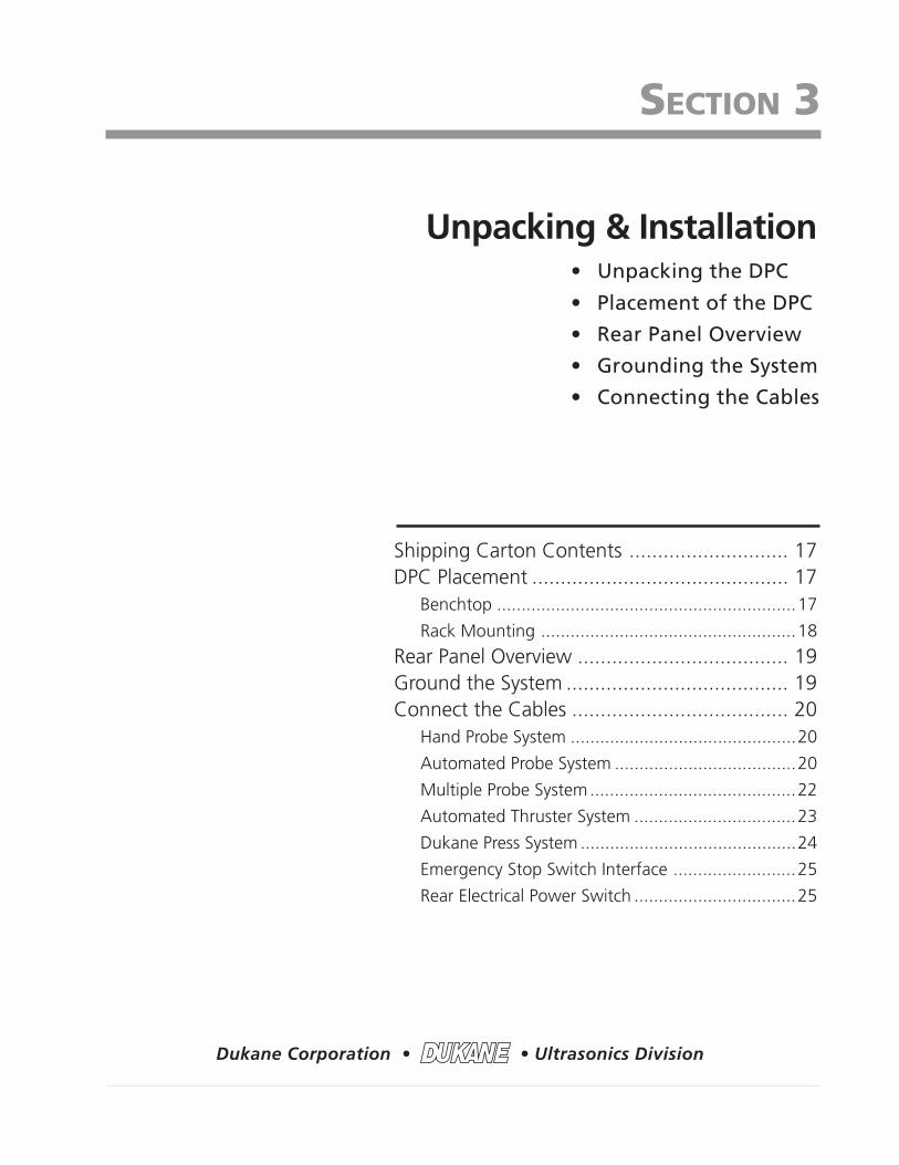
The 3–prong AC Line cords supplied arematched to the DPC II Plus power rating andthe continent of specified use.The part numbers are —200–1109 North America 110V200–1110 North America 220V200–1111 Continental Europe
Figure 3-4 DPC II Plus Hand Probe Cable Connections
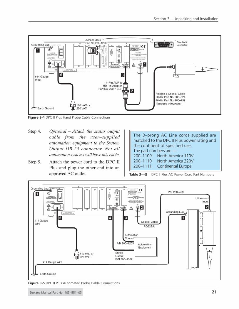
Figure 3-5 DPC II Plus Automated Probe Cable Connections
Table 3—II DPC II Plus AC Power Cord Part Numbers
Step 4. Optional – Attach the status outputcable from the user–suppliedautomation equipment to the SystemOutput DB-25 connector. Not allautomation systems will have this cable.
Step 5. Attach the power cord to the DPC IIPlus and plug the other end into anapproved AC outlet.
22 Dukane Manual Part No. 403–551–03
Dynamic Process Controller DPC™ II Plus – User’s Manual
���
DUKANE CORPST. CHARLES, IL 60174MADE IN USA
SERIAL NUMBER
US 10000
– WARNING! –POWERLINE MUST BE GROUNDED
AT OUTLET
REMOVE ALL POWER BEFOREREMOVING COVER OR CONNECTING
OR DISCONNECTING CABLES.
ULTRASOUNDOUTPUT
SYSTEM OUT SYSTEM IN
J1
U.S.PATENT 4,277,710
– WARNING–POWER LINE MUST BEGROUNDED AT OUTLET
LINE VOLTAGE200–240Vac 50/60Hz
15A
MODEL NUMBER200-240 VAC, 50-60Hz, 15A
Remote AmpltdControl Mod.
Current Loop Status
POS
NEG
SHLD
+
–
Power MonitorJacks
Power SignalOutput Module
PowerSignalOutput
ZeroAdjust
1
2
3
4
5
6
7
8
Earth Ground
#14 GaugeWire
110 VAC or220 VAC
Grounding Lug
GroundingLug
UltrasoundInput(s)
AutomationControl
Multi–ProbeMaster Module
Ultrasonic InputRG62B/U Coax
Status OutputP/N 200–1302
Coaxial Cable(s)
RG62B/U
#14 Gauge Wire
AutomationEquipment
P/N 200–1203
P/N 200–479
�
�
�
� � �
� ��
��
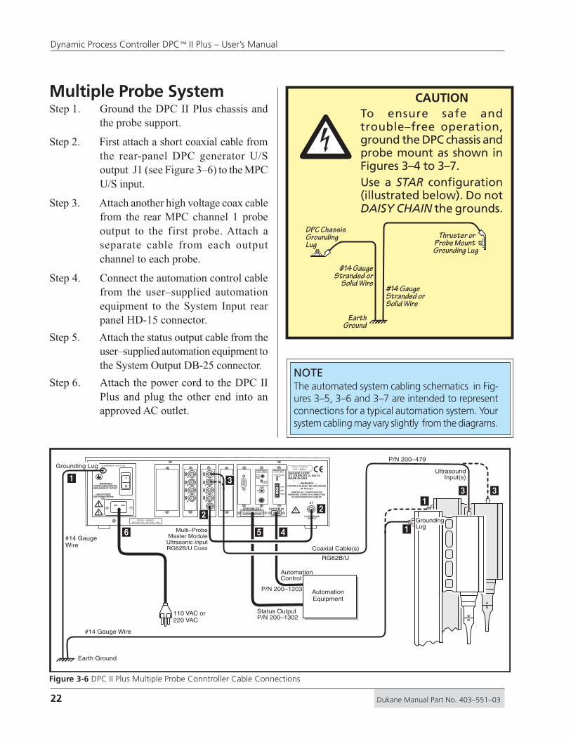
Figure 3-6 DPC II Plus Multiple Probe Conntroller Cable Connections
NOTEThe automated system cabling schematics in Fig-ures 3–5, 3–6 and 3–7 are intended to representconnections for a typical automation system. Yoursystem cabling may vary slightly from the diagrams.
CAUTIONTo ensure safe andtrouble–free operation,ground the DPC chassis andprobe mount as shown inFigures 3–4 to 3–7.Use a STAR configuration(illustrated below). Do notDAISY CHAIN the grounds.
�Multiple Probe SystemStep 1. Ground the DPC II Plus chassis and
the probe support.
Step 2. First attach a short coaxial cable fromthe rear-panel DPC generator U/Soutput J1 (see Figure 3–6) to the MPCU/S input.
Step 3. Attach another high voltage coax cablefrom the rear MPC channel 1 probeoutput to the first probe. Attach aseparate cable from each outputchannel to each probe.
Step 4. Connect the automation control cablefrom the user–supplied automationequipment to the System Input rearpanel HD-15 connector.
Step 5. Attach the status output cable from theuser–supplied automation equipment tothe System Output DB-25 connector.
Step 6. Attach the power cord to the DPC IIPlus and plug the other end into anapproved AC outlet.
EarthGround
#14 GaugeStranded or
Solid Wire#14 GaugeStranded orSolid Wire
Thruster or Probe Mount Grounding Lug
DPC ChassisGroundingLug

23Dukane Manual Part No. 403–551–03
Section 3 – Unpacking and Installation
Figure 3-7 DPC II Plus Automated Thruster Cable Connections
Automated Thruster SystemStep 1. Ground the DPC II Plus and the
Thruster as shown in Figure 3–7.
Step 2. Attach the high voltage RG62B/U coaxcable from the rear-panel DPC II Plusconnector J1 to the ultrasound input J1on the thruster (see Figure 3–7).
Step 3. Connect the Automation Control cablefrom the user–supplied automationequipment to the System Input rearpanel HD-15 connector.
Step 4. Attach the Status Output cable from theuser–supplied automation equipment tothe Status Output DB-25 connector.
Step 5. Connect the Press Base Input cablefrom J35 on the Press Base to the DB-9
connector (J902) on the Press ControlModule. If the automation system doesnot have a connection to J902, you mayneed a jumper block (Part No. 200-1293)to replace the normally closed contactfrom the press base Emergency Stopsafety switch.
Step 6. Connect the Operational Control cablefrom the user–supplied automationequipment to the 36–contact Thrustercontrol connector (J901) on the PressControl Module.
Step 7. Attach the power cord to the DPC IIPlus and plug the other end into anapproved AC outlet.
���
DUKANE CORPST. CHARLES, IL 60174MADE IN USA
SERIAL NUMBER
US 10000
– WARNING! –POWERLINE MUST BE GROUNDED
AT OUTLET
REMOVE ALL POWER BEFOREREMOVING COVER OR CONNECTING
OR DISCONNECTING CABLES.
ULTRASOUNDOUTPUT
SYSTEM OUTJ901
TO
TH
RU
ST
ER
J902
BA
SE
/A
BO
RT
+
–
Power MonitorJacks
Power SignalOutput Module
PowerSignalOutput
ZeroAdjust
SYSTEM IN
J1
U.S.PATENT 4,277,710
– WARNING–POWER LINE MUST BEGROUNDED AT OUTLET
LINE VOLTAGE200–240Vac 50/60Hz
15A
MODEL NUMBER200-240 VAC, 50-60Hz, 15A
Remote AmpltdControl Mod.
Current Loop Status
POS
NEG
SHLD
J1J40
J3
80–100 psi
Air Supply
Earth Ground
#14 GaugeWire
110 VAC or220 VAC
Grounding Lug
Grounding Lug
Coaxial Cable
RG62B/U
#14 Gauge Wire
Top–Of–Stroke (Optional)
J901 Operational Control
Part No. 200–1104
AutomationEquipment
UltrasoundInput
AutomationControlCableP/N 200–1203
StatusOutputCable
Base Cable
Part No. 200–1124 — or —
Jumper BlockPart No. 200–1293
P/N 200–1302
P/N 438–528P
/N 2
00–4
79
�
�
�
�
� � � �
�
to J902 Pins 3 & 9Connected
1 53
6 9

24 Dukane Manual Part No. 403–551–03
Dynamic Process Controller DPC™ II Plus – User’s Manual
���
DUKANE CORPST. CHARLES, IL 60174MADE IN USA
SERIAL NUMBER
US 10000
– WARNING! –POWERLINE MUST BE GROUNDED
AT OUTLET
REMOVE ALL POWER BEFOREREMOVING COVER OR CONNECTING
OR DISCONNECTING CABLES.
ULTRASOUNDOUTPUT
SYSTEM OUTJ901
TO
TH
RU
ST
ER
J902
BA
SE
/A
BO
RT
+
–
Power MonitorJacks
Power SignalOutput Module
PowerSignalOutput
ZeroAdjust
SYSTEM IN
J1
U.S.PATENT 4,277,710
– WARNING–POWER LINE MUST BEGROUNDED AT OUTLET
LINE VOLTAGE200–240Vac 50/60Hz
15A
MODEL NUMBER200-240 VAC, 50-60Hz, 15A
Remote AmpltdControl Mod.
Current Loop Status
POS
NEG
SHLD
80–100 psi
Air Supply
J35
J1J40
J3
Part No. 200–1124
Part No. 200–1104
Operational Control
8–conductor cable
Grounding LugEarth Ground
#14 GaugeWire
#14 Gauge Wire
#14 Gauge Wire
Coaxial Cable
RG62B/U
J901 toThruster J902 to
Base/Abort
Par
t No.
200
–479
110 VAC or220 VAC
GroundingLug
Ultrasound Input
�
�
�
� �
�
�
�
�
�
Figure 3-8 DPC II Plus Dukane Press Cable Connections
Dukane Press SystemStep 1. Ground the DPC II Plus, the Thruster
and the Base as shown in Figure 3–8.
Step 2. Attach the high voltage coax cablefrom the press J1 connector to the DPCUltrasound Out connector (J1).
Step 3. Connect the Press Base Input cablefrom J35 on the Press Base to the DB-9 connector (J902) on the PressControl Module.
Step 4. Connect the Operational Control cablefrom J3 at the top of the press to the36–contact Thruster control connector(J901) on the Press Control Module.
Step 5. Attach the power cord to the DPC IIPlus and plug the other end into anapproved AC outlet.
CAUTION
Use the STAR configurationillustrated below and inFigure 3–8 to ground theDPC chassis, base andthruster. Do not DAISYCHAIN the grounds.
�
Base/FixtureGroundingLug
EarthGround
#14 GaugeStranded or
Solid Wire
#14 GaugeStranded orSolid Wire
ThrusterGrounding
Lug
DPC ChassisGroundingLug

25Dukane Manual Part No. 403–551–03
Section 3 – Unpacking and Installation
Figure 3-10 Rear Panel AC Breaker Switch
Figure 3-9 J902 Emergency Stop Interface Example
Emergency Stop SwitchFigure 3–9 is a simplified example that demon-strates the basic requirements to interface with theDPC II Plus on J902. This is excerpted from Ap-plication Note AN201 available on our website.Note that the emergency stop inputs cannot justbe tied together from multiple DPCs when used
on a common welding process. Multiple DPCs re-quire individual contacts for each unit.
Check with your local safety compliance officebefore altering the factory connections. The useris responsible for complying with all requirementsof the safety regulatory agencies governing thegeographic location where the Dukane equipmentwill be operated.
Rear ACBreaker/PowerSwitch
Rear ACBreaker/PowerSwitch
GroundingLug
IECAC PowerInput
Electrical Power SwitchThe rear panel AC breaker switch (Figure 3–10)is wired in series with the front panel breakerswitch (shown in Figure 4-2). When the rearbreaker switch is off, it isolates the AC power feedin the chassis for safety considerations. Both thefront panel and rear panel switches must be on tosupply AC power to the DPC generator.
J902
4
3
9
7
Cable No. 200–1124
+24V DC
E–Stop Sense
E–Stop Switch
EmergencyStop Features
To DukanePneumatic
Press
+22V DC DPC II orDPC II Plus
EmergencyStop Switch

26 Dukane Manual Part No. 403–551–03
Dynamic Process Controller DPC™ II Plus – User’s Manual
This page intentionally left blank
27Dukane Manual Part No. 403–551–03
Section 3 – Unpacking and Installation
Controls & Displays
Dukane Corporation • • Ultrasonics Division
SECTION 4
Front Panel Layout ........................................ 29AC Power ..................................................... 30Generator Status Panel ................................. 30
Generator Control Keys ........................................30
System Status Display ...........................................31
System Power Output Display...............................32
Process Control Panel .................................... 33Menu Function Keys .............................................33
Control Menu Display ..........................................35
• Front Panel Layout
• AC Power
• Generator Status Panel
• Menu Function Keys
• Control Menu Display

28 Dukane Manual Part No. 403–551–03
Dynamic Process Controller DPC™ II Plus – User’s Manual
This page intentionally left blank

29Dukane Manual Part No. 403–551–03
Section 4 – Controls & Displays
Front Panel LayoutThis section describes the DPC II Plus front panel con-trols, status, power output and menu displays.
The DPC front panel is laid out in three sections asillustrated below in Figure 4-1. The three sections are
1. AC Power switch and indicator �
2. Generator Status Panel which contains
• Three Generator Control keys �
• System Status display �
• System Power Output display �
3. Process Control Panel which contains
• Twelve Menu Function keys �
• LCD menu display �
DPC II Plus v1.50PRESS ENERGYMORE INFO:www.dukcorp.com/us/ FAULT
ON LINEINPUT TESTOVERTEMP
OVERLOADOFF LINE
HOLD
MODE
ENTER
WELDP2
WELDP1
GEN.INFO
AMP.ADJUST
CANCEL
Figure 4–1 DPC II Plus Front Panel Layout
�
�
���
�

30 Dukane Manual Part No. 403–551–03
Dynamic Process Controller DPC™ II Plus – User’s Manual
1. AC Power SectionThe front-panel AC power section has a switch andpower indicator that is shown in Figure 4-2.
ON/OFF The AC power switch connects ACpower to the generator. This breakerswitch is wired in series with the rearpanel power switch (Figure 3–9). It alsoserves as a circuit breaker that providesoverload protection for the DPC. Bothswitches must be turned on to supplyAC power to the generator.
Green LED The green indicator above the switchlights when the DC bus is up, after theAC power has been switched on. Atthis point the generator is capable ofproducing an ultrasonic output signal.
2. Generator Status PanelThe Generator Status Panel is subdivided into threesections which provide control and status displays.
1. Generator Control Keys
2. System Status Display
3. System Power Output Display
Generator Control KeysThe Generator Control Key section consists of threekeys as shown in Figure 4-3.
ON LINE This places the generator in an opera-tional state. It can produce an ultra-sonic output signal when triggered.
TEST The TEST key momentary activates thegenerator to provide ultrasound out-put for test or setup purposes. TESTwill only work in the ON LINE state.
OFF LINE This key places the generator in astandby mode. This prevents the gen-erator from producing an ultrasonicoutput signal.
GreenPowerIndicator
FrontAC PowerSwitch
ON LINE Key
TEST Key
OFF LINE Key
Figure 4–3 Generator Control Keys
Figure 4–2 Front Panel AC Power Section
NOTEIf a Press module is installed, these keys areonly active if the Emergency Stop is notengaged. If the Emergency Stop switch isdepressed, the System Status Display willnot be lit and the Control Keys inactive.
31Dukane Manual Part No. 403–551–03
Section 4 – Controls & Displays
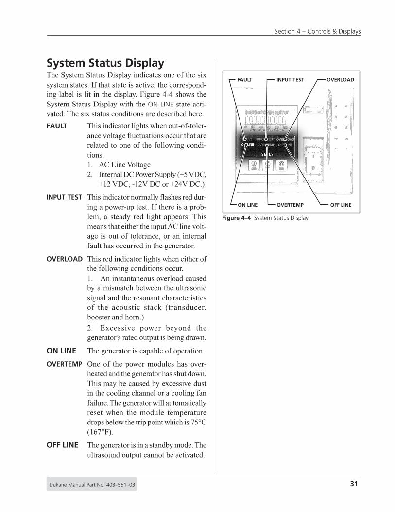
System Status DisplayThe System Status Display indicates one of the sixsystem states. If that state is active, the correspond-ing label is lit in the display. Figure 4-4 shows theSystem Status Display with the ON LINE state acti-vated. The six status conditions are described here.
FAULT This indicator lights when out-of-toler-ance voltage fluctuations occur that arerelated to one of the following condi-tions.1. AC Line Voltage2. Internal DC Power Supply (+5 VDC,
+12 VDC, -12V DC or +24V DC.)
INPUT TEST This indicator normally flashes red dur-ing a power-up test. If there is a prob-lem, a steady red light appears. Thismeans that either the input AC line volt-age is out of tolerance, or an internalfault has occurred in the generator.
OVERLOAD This red indicator lights when either ofthe following conditions occur.1. An instantaneous overload causedby a mismatch between the ultrasonicsignal and the resonant characteristicsof the acoustic stack (transducer,booster and horn.)
2. Excessive power beyond thegenerator’s rated output is being drawn.
ON LINE The generator is capable of operation.
OVERTEMP One of the power modules has over-heated and the generator has shut down.This may be caused by excessive dustin the cooling channel or a cooling fanfailure. The generator will automaticallyreset when the module temperaturedrops below the trip point which is 75°C(167°F).
OFF LINE The generator is in a standby mode. Theultrasound output cannot be activated.
ON LINE OVERTEMP OFF LINE
FAULT INPUT TEST OVERLOAD
Figure 4–4 System Status Display

32 Dukane Manual Part No. 403–551–03
Dynamic Process Controller DPC™ II Plus – User’s Manual
System Power Output DisplayThe tricolor System Power Output Display indi-cates the percentage of ultrasonic power beingdrawn by the load.
Green Eight green vertical bars indicating10% to 80% power output are dis-played during normal operation. Fig-ure 4-5 shows the display indicating80% output power.
Yellow Two yellow bars for 90% and 100%power output warn that the genera-tor is operating near its maximumrated output.
Red The last red bar indicates that thegenerator is in an overload conditiondelivering more than its rated out-put power. Figure 4-6 shows the redoverload and two yellow warning in-dicators. The red warning indicatorlights up just prior to an overloadcondition. The ultrasonic signal isshut down when an overload condi-tion occurs.
GREEN
YELLOW RED
Figure 4–6 Warning Indicators
Figure 4–5 Normal Operation
NOTEThe available output power is directly propor-tional to the Amplitude setting.Example: A 2200 Watt rated DPC set to 80%Amplitude will overload at 1760 Watts.(2200W x 0.80 = 1760 Watts)

33Dukane Manual Part No. 403–551–03
Section 4 – Controls & Displays
3. Process Control PanelMenu Function KeysThe twelve menu keys are shown in Figure 4–7.Their function is described going across each rowstarting at the upper left.
Pressing the GEN. INFO key dis-plays the DPC model, the firmwareversion and the installed modules. Areadout for a DPC II Plus equippedwith both a Press Control moduleand a Power Signal Output Moduleis shown in Figure 4–8. Press CAN-CEL to return to the previous menu.
The up arrow key increments the datavalue each time it is pushed. Hold-ing the key in continuously incre-ments the value. This key is also usedto move the cursor up one line on amenu selection screen
Pressing the HOLD key immediatelybrings you to the Hold Time dataentry menu. You can quickly checkand/or change the setting using thefour arrow keys. Pressing ENTERcompletes the process and returnsyou to your last menu screen.
Pressing the WELD P1 key displaysthe parameter(s) for the first pressuresetting. The value(s) can be quicklychecked and/or altered without go-ing back through the menu sequence.Pressing ENTER completes the pro-cess and returns you to your lastmenu screen.
Pressing the left arrow key selectsthe next digit to the left of a param-eter setting. The key is used whenentering values and moves the flash-ing bar under the selected digit. Theselection wraps around to the rightdigit after the left most digit posi-tion is reached.
+
–
HOLDWELD
P1
WELD
P2
GEN.
INFO
AMP.
ADJUSTCANCELENTER
MODE
AmplitudeAdjust
Decrement Enter
RightArrow
Cancel
Weld(Pressure 2)
GeneralInformation
IncrementHold Weld
(Pressure 1)
LeftArrow
Mode
DPC II Plus v1.50PRESS + ENERGYMORE INFO:www.dukcorp.com/us/
GEN.INFO
WELDP1
HOLD
Figure 4–7 Menu Keys
Figure 4–8 GEN INFO Display
NOTEFor three of the ‘hot’ keys (HOLD, WELD P1,and WELD P2), data can only be entered ormodified after the programming setup iscompleted.
34 Dukane Manual Part No. 403–551–03
Dynamic Process Controller DPC™ II Plus – User’s Manual
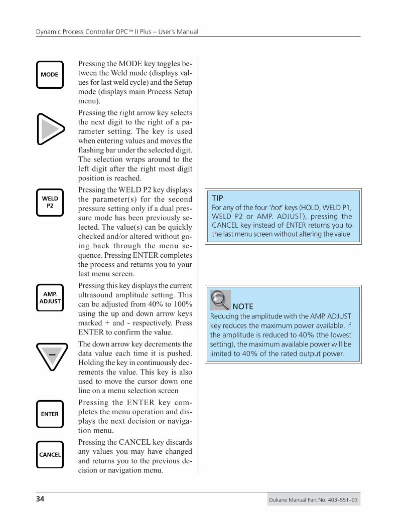
Pressing the MODE key toggles be-tween the Weld mode (displays val-ues for last weld cycle) and the Setupmode (displays main Process Setupmenu).
Pressing the right arrow key selectsthe next digit to the right of a pa-rameter setting. The key is usedwhen entering values and moves theflashing bar under the selected digit.The selection wraps around to theleft digit after the right most digitposition is reached.
Pressing the WELD P2 key displaysthe parameter(s) for the secondpressure setting only if a dual pres-sure mode has been previously se-lected. The value(s) can be quicklychecked and/or altered without go-ing back through the menu se-quence. Pressing ENTER completesthe process and returns you to yourlast menu screen.
Pressing this key displays the currentultrasound amplitude setting. Thiscan be adjusted from 40% to 100%using the up and down arrow keysmarked + and - respectively. PressENTER to confirm the value.
The down arrow key decrements thedata value each time it is pushed.Holding the key in continuously dec-rements the value. This key is alsoused to move the cursor down oneline on a menu selection screen
Pressing the ENTER key com-pletes the menu operation and dis-plays the next decision or naviga-tion menu.
Pressing the CANCEL key discardsany values you may have changedand returns you to the previous de-cision or navigation menu.
CANCEL
WELDP2
ENTER
AMP.ADJUST
MODE
TIPFor any of the four ‘hot’ keys (HOLD, WELD P1,WELD P2 or AMP. ADJUST), pressing theCANCEL key instead of ENTER returns you tothe last menu screen without altering the value.
NOTEReducing the amplitude with the AMP. ADJUSTkey reduces the maximum power available. Ifthe amplitude is reduced to 40% (the lowestsetting), the maximum available power will belimited to 40% of the rated output power.

35Dukane Manual Part No. 403–551–03
Section 4 – Controls & Displays
Process Control Menu DisplayThe menu display is a backlit 4–line LCD with 20characters per line. The top line of the display con-tains the menu title (with a few exceptions).
Selection MenusThe selection menus have a triangular cursor atthe far right of the display. These menus may alsobe thought of as a decision menu. Move the cursorto the menu choice and press the ENTER key toselect your choice. Pressing the CANCEL key re-turns to the previous selection menu. A typical se-lection menu is shown in Figure 4–9.
PROCESS CONTROLWELD MODEHOLD TIMEAFTERBURST
Confirmation Menus
A confirmation menu requests a Yes or No entryto continue the process. Select YES from the menuand press the ENTER key to proceed. A typical con-formation menu is shown in Figure 4–10.
RESET PART COUNT NO YES
Data Entry Menu
The data entry screens have the parameter nameon the first line and the parameter value on thethird line. Use the left and right triangle keys toselect the digit and the Increment (+) and Decre-ment (–) keys to change the value. Press the EN-TER key to accept the value. A typical data entryscreen is shown in Figure 4–11.
WELD TIME
0.750 SEC
Figure 4–9 Typical Selection menu
Figure 4–11 Typical Data Entry Screen
Figure 4–10 Typical Confirmation Screen

36 Dukane Manual Part No. 403–551–03
Dynamic Process Controller DPC™ II Plus – User’s Manual
This page intentionally left blank

37Dukane Manual Part No. 403–551–03
Section 4 – Controls & Displays
Rear Connectors
Dukane Corporation • • Ultrasonics Division
SECTION 5
Rear Panel Layout ......................................... 39System Input Connector ............................... 40System Output Connector ............................ 42Remote Amplitude Control ........................... 46Power Output Module Option....................... 47Press Control Module Option ........................ 48Multi–Probe Module Options ........................ 51Jumper Block Options ................................... 52
Status Driver Normal Selection State.....................52
Status Driver Selection ..........................................52
Automation Cycle Stop or End Of Weld ...............52
Switch Debounce Filter Time Delay .......................52
Timer Board Enable/Bypass ...................................52
System Control Inputs ..........................................53
Card Slot and Jumper Block Locations ..................53
• Rear Panel Layout
• System Input
• System Output
• Optional Modules
• Internal Jumper Blocks

38 Dukane Manual Part No. 403–551–03
Dynamic Process Controller DPC™ II Plus – User’s Manual
This page intentionally left blank

39Dukane Manual Part No. 403–551–03
Section 5 – Rear Connectors
Rear Panel LayoutAll of the connectors contained on the DPC IIPlus and the optional modules are shown belowin Figure 5–1. No generator will have all the mod-ules shown. Specifically the Multi–Probe Control-ler and the Press Control Modules are mutuallyexclusive. The modules are shown here to indi-cate their installed locations and connector types.
Multi–ProbeSlave U/SOutputs
Multi–ProbeMaster U/SOutputs
Press BaseAbort
Power SignalOutput Monitor
EEPROM SerialProgramming Port
Remote AmplitudeControl
IECAC PowerInput Ultrasound
Output
SystemInput
Multi–ProbeMaster U/S
InputSystemOutput
ThrusterOperational
Control
Rear ACPower Switch
GroundingLug
Figure 5–1 DPC II Plus Rear Panel Connectors

40 Dukane Manual Part No. 403–551–03
Dynamic Process Controller DPC™ II Plus – User’s Manual
System Input ConnectorThe System Input is a HD-15 (high-density, 15contact) female connector. Pin assignments areshown in Figure 5–2. Table 5—I below lists thepinout and signal name for the System Input con-nector. A complete description of the input signalsand their function is given on the next page. Usersof custom automation will also find a list of wirecolor codes for the Dukane 200–1203 I/O cableassembly in Table 5—III. This cable is used toconnect the DPC to custom automation equipmentto control the welding process.
1 2 3 4 5
6 10
11 12 13 14 15
Pin Signal Name Signal Description
Iso Common Isolated Input Common (if jumper isselected – Figure 5–9/SH707)
10 Not Used Reserved for Future Use
12 Setup I.D. Bit 0 Remote Setup Selection Bit #0 (LSB)
13 Setup I.D. Bit 1 Remote Setup Selection Bit #1
14 Setup I.D. Bit 2 Remote Setup Selection Bit #2 (MSB)
+22VDC Current limited to 250 mA maximum1
Gnd 22VDC Return (DPC Chassis Ground)2
Iso Oper In Isolated Operate Input3
4
Iso Press Cntrl Isolated Press Control5
Not Used Spare Input Pin6
Gnd 22VDC Return (DPC Chassis Ground)7
Sw Oper Input Switch Closure Operate Input8
Iso Auto Stop Isolated Automation Stop Input —OR—Isolated Automation End–Of–Weld(set by jumper SH704 see Figure 5–12)
9
15 F P Lock Front Panel Control Lock
11 Hand Probe Press InhibitHPPI
5 4 3 2 1
610
15 14 13 12 11
Pin14
Pin13
Pin12
TimerSetup File
MPC ProbeSelected
0 0 0 File 1
File 2
File 3
File 4
File 5
File 6
File 7
File 8
Probe 1
Probe 2
Probe 3
Probe 4
Probe 5
Probe 6
Probe 7
Probe 8
0 0 1
0 1 0
0 1 1
1 0 0
1 0 1
1 1 0
1Note: 1 = Pin Grounded (to DPC chassis) 0 = Pin Open (no connection)
1 1
Figure 5–3 Cable end of SYSTEM IN connector.
Table 5—I System Input Connector Signals
Figure 5–2 HD-15F System Input Connector
Table 5—II Remote Setup File Selection
NOTEThe connector pinout in Figure 5–2 isthe female DPC panel connector. Themale cable end is a mirror image and isshown in Figure 5–3.
CAUTIONThe System Input portuses the same type ofconnector as a standardcomputer video monitorport, but it is electricallyvery different. DO NOT
connect any video monitor devicesto this connector. Doing so may re-sult in damage to both the videodevice and the DPC.
�

41Dukane Manual Part No. 403–551–03
Section 5 – Rear Connectors
Input Signal DescriptionPin 1 (+22V)This pin can supply +22VDC at up to 250mA topower the user's automation controls.
Pin 2 (Gnd)Pin 2 and 7 are the 22VDC and Operate returnsand are tied to the chassis ground.
Pin 3 (Isolated Operate In)This pin is used to initiate the operate sequence.The factory default setting is a non-isolated sinkrequiring a dry contact closure to ground (pins 2or 7). This input can be changed to a source orfully isolated input by jumper block SH707. SeeFigures 5–11, 5–12 and Appendix C.
Pin 4 (Isolated Common)This pin is used as the isolated return common ifjumper block SH707 is configured as a fully iso-lated input (position JU726). See Figures 5–11,5–12 and Figure C-5.
Pin 5 (Isolated Press Control)This input is designed to be used in conjunctionwith the optional Press Control Board. The signalis used to activate the thruster up and down. Thefactory default setting is a non-isolated sink re-quiring a dry contact closure to ground (pins 2 or7). This input can be changed to a source or fullyisolated input by jumper block SH707. See Fig-ures 5–11, 5–12 and Appendix C.
Pin 6 (Not Used)Isolated input reserved for future use.
Pin 7 (Gnd)Pin 2 and 7 are the 22VDC and Operate returnsand are tied to the chassis ground.
Pin 8 (Operate)A dry contact closure (no voltage) between pin 8and ground (pins 2 or 7) will initiate the operatesequence and is functionally the same as pin 3.
Pin 9 (Isolated Auto Stop)This signal stops the operation sequence. The fac-tory default setting is a non-isolated sink requir-ing a dry contact closure to ground (pins 2 or 7).
Table 5—III System Input Cable Color Code (P/N 200–1203)
This input can be changed to a source or fully iso-lated input by jumper block SH707. See Figures5–11, 5–12 and Appendix C.
Pin 10 (Not Used)Isolated input reserved for future use.
Pin 11 (Hand Probe Press Inhibit)The adapter cable (P/N 200–1203) has pin 11grounded to indicate a hand probe is connected.
Pins 12, 13, 14 (Remote Setup)These pins are used to select one of eight setupfiles. When using the multi–probe controller mod-ule (MPC), these bits also select which probe isactivated. A dry contact closure between pins 12,13 or 14 and ground (pins 2 or 7) will activate oneof the setup files. The pin combinations to selectsetup files 1 through 8 are given in Table 5—II.Note that file 1 is the default selection.
Pin 15 (F P Lock)A dry contact closure between pin 15 and ground(pins 2 or 7) will lock out the front panel TESTkey and prevent it from being activated. This alsoprevents any programming changes.
Pin Color Signal Desc Note
10 Blue Reserved
11 Orange/Blk Hand ProbePress Inhibit
Black may be faint –Don't confuse with 9
13 Green/Blk Remote SetupSelection
14 Black/Wht Remote SetupSelection (MSB)
Black Gnd Also connected toconnector metal shell2
Blue/Blk Iso Oper In3
Green/Wht Iso Common4
Blue/Wht Iso Auto Cntrl5
Orange Iso Auto Stop9
15 Green F P Lock
+22V Red used by Beldenmay appear brown1 Red
Reserved Red used by Beldenmay appear brown6 Red/Blk
Gnd7 White/Blk
Sw Oper Input8 White
12 Remote SetupSelection (LSB)
Red used by Beldenmay appear brownRed/Wht
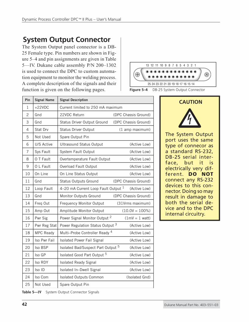
42 Dukane Manual Part No. 403–551–03
Dynamic Process Controller DPC™ II Plus – User’s Manual
System Output ConnectorThe System Output panel connector is a DB-25 Female type. Pin numbers are shown in Fig-ure 5–4 and pin assignments are given in Table5—IV. Dukane cable assembly P/N 200–1302is used to connect the DPC to custom automa-tion equipment to monitor the welding process.A complete description of the signals and theirfunction is given on the following pages.
Table 5—IV System Output Connector Signals
The System Outputport uses the sametype of connecor asa standard RS-232,DB-25 serial inter-face, but it iselectrically very dif-ferent. DO NOTconnect any RS-232devices to this con-nector. Doing so mayresult in damage toboth the serial de-vice and to the DPCinternal circuitry.
�CAUTIONPin Signal Name Signal Description
+22VDC Current limited to 250 mA maximum
Gnd 22VDC Return (DPC Chassis Ground)
Gnd Status Driver Output Ground (DPC Chassis Ground)
Stat Drv Status Driver Output (1 amp maximum)
Not Used Spare Output Pin
U/S Active Ultrasound Status Output (Active Low)
Sys Fault System Fault Output (Active Low)
O T Fault Overtemperature Fault Output (Active Low)
O L Fault Overload Fault Output (Active Low)
10 On Line On Line Status Output (Active Low)
11 Gnd Status Outputs Ground (DPC Chassis Ground)
12 Loop Fault 4–20 mA Current Loop Fault Output 1 (Active Low)
13 Gnd Monitor Outputs Ground (DPC Chassis Ground)
14 Freq Out Frequency Monitor Output (31Vrms maximum)
15 Amp Out Amplitude Monitor Output (10.0V = 100%)
16 Pwr Sig Power Signal Monitor Output 2 (1mV = 1 watt)
17 Pwr Reg Stat Power Regulation Status Output 3 (Active Low)
18 MPC Ready Multi–Probe Controller Ready 4 (Active Low)
19 Iso Pwr Fail Isolated Power Fail Signal (Active Low)
20 Iso BSP Isolated Bad/Suspect Part Output 5 (Active Low)
21 Iso GP Isolated Good Part Output 5 (Active Low)
22 Iso RDY Isolated Ready Signal (Active Low)
23 Iso ID Isolated In–Dwell Signal (Active Low)
24 Iso Com Isolated Outputs Common (Isolated Gnd)
25
1
2
3
4
5
6
7
8
9
Not Used Spare Output Pin
13 12 11 10 9 8 7 6 5 4 3 2 1
25 24 23 22 21 20 19 18 17 16 15 14
Figure 5–4 DB-25 System Output Connector
43Dukane Manual Part No. 403–551–03
Section 5 – Rear Connectors
Output Signal DescriptionPin 1 (+22V)This pin can supply +22VDC to supply power foruser automation controls. It is limited to 250mA.
Pin 2 (Gnd)Pin 2 is the 22VDC and Status Out return. It is tiedto the chassis ground.
Pin 3 (Gnd)Pin 3 is the 22VDC and Status Out return. It is tiedto the chassis ground.
Pin 4 (Status Driver)An active low output on pin 4 indicates the conditionset on Jumper Block SH702 has occurred (see Fig-ures 4-7 and 4-8). The factory default is OVERLOAD.
Pin 5 (Not Used)Pin 5 is reserved for future use.
Pin 6 (U/S Active)An active low output on pin 6 indicates the ultra-sound is being delivered to the probe.
Pin 7 (System Fault)An active low output on pin 7 indicates the generatorhas detected an out of tolerance voltage fluctuation.The front panel status display will indicate FAULT.
Pin 8 (OVERTEMP)An active low output on pin 8 indicates that one ofthe power modules in the generator has overheatedand automatically shut down. The front panel statusdisplay will indicate OVERTEMP.
Pin 9 (OVERLOAD)An active low output on pin 9 indicates that exces-sive power beyond the generators rated output is be-ing drawn. The ultrasonic signal is shut down whenan overload condition is detected. The front panelstatus display will indicate OVERLOAD. The over-load signal resets when the operate input deactivatesor the TEST switch is released.
NOTEActive Low outputs are open collectorDarlington transistors that sink current toground (either chassis ground or isolated com-mon @20mA maximum).Custom automation users must supply their ownpullups. See Appendix C for sample circuits.

44 Dukane Manual Part No. 403–551–03
Dynamic Process Controller DPC™ II Plus – User’s Manual
Pin 10 (ON LINE)An active low output on pin 10 indicates the gen-erator is on line and is capable of being triggeredexternally. The front panel status display will indi-cate ON LINE.
Pin 11 (Gnd)Pin 11 is the 22VDC and Status Out return. It is tiedto the chassis ground.
Pin 12 (Current Loop Fault)1
An active low output on pin 12 indicates the 4–20mAcurrent loop output has a fault. This output is onlyavailable when a Remote Amplitude Control mod-ule is installed.
Pin 13 (Monitor Gnd)Pin 13 provides a return path to the chassis groundfor the monitor outputs on pins 14, 15 and 16.
Pin 14 (Freq Out)The signal on pin 14 is the actual output frequency.It is a sine wave with an amplitude of 31Vrms maxi-mum.
Pin 15 (Amp Out)The signal on pin 15 is proportional to the outputsignal amplitude. The scale is 10.0V = 100%. Thisallows automation equipment to monitor the DPCamplitude setting.
Pin 16 (Pwr Sig)2
This output is only available when the optional PowerSignal Output module (part 438-826 ) is installed.The signal on pin 16 is proportional to the true RMSultrasonic output power being drawn from the DPC.The scale is 1mV = 1Watt on the 20kHz, 30kHz and40kHz models. The maximum full scale output is4.095V (4,095 Watts). On the 50kHz and 70kHzmodels, the scale factor is 10mV = 1 Watt with amaximum scaled output of 409.5 Watts.
Pin 17 (Pwr Reg Status)3
This option is not currently available.

45Dukane Manual Part No. 403–551–03
Section 5 – Rear Connectors
Pin 18 (MPC Ready)4
An active low output on pin 18 indicates the MPCmodule (Multi–Probe Controller) is ready and willaccept probe selection changes on the Remote Setupinputs.
Pin 19 (Iso Power Fail)An active low output indicates that AC power is withinoperating range. This output will turn off (high im-pedance state which no longer sinks current), if theAC power fails or is switched off.
Pin 20 (Iso Bad/Suspect Part)5
An active low output that indicates the weld cycle isoutside the boundary limits set in the Bad Limitsmenu. This signal activates when the ultrasonic out-put is terminated at the end of the weld. The de-fault setting is maintained which means the signalremains active until the beginning of the next cycle.If the Utilities menu option is set to momentary,the signal is pulsed for 100 msec.
Pin 21 (Iso Good Part)5
An active low output that indicates the weld cycledid not cross the boundary limits set in the Suspect orBad Limits menu. This signal activates when the ul-trasonic output is terminated at the end of the weld.The default setting is maintained which means thesignal remains active until the beginning of the nextcycle. If the Utilities menu option is set to momen-tary, the signal is pulsed for 100 msec.
Pin 22 (Iso Ready)An active low output that occurs at the end of allportions of the weld cycle. The signal remains ac-tive until the beginning of the next cycle.
Pin 23 (Iso In–Dwell)This output is active low while the ultrasonic outputsignal has been turned off during the HOLD time ofthe weld cycle.
FOOTNOTES
1 Requires a Remote Amplitude Control module.
2 Requires a Power Signal Output module.
3 Not presently available.
4 Requires a Multi–Probe Controller module.
5 Requires the standard DPC II Plus timer feature.
Pin 24 (Iso Common)5
Pin 24 provides the return path for the isolated out-put signals on pins 19, 20, 21, 22 and 23.
Pin 25 (Not Used)Pin 25 is reserved for future use.

46 Dukane Manual Part No. 403–551–03
Dynamic Process Controller DPC™ II Plus – User’s Manual
Remote Amplitude ControlModulePart No. 438–799This optional module enables remote control ofoutput amplitude of the DPC II Plus. The controlinterface is a 4–20mA current loop. The currentloop connector and fault indicator are shown inFigure 5–5. The output can be adjusted from 36%to 100%. The scale factor is ∆16mA = ∆64%which is ∆1mA = ∆4%. The graph of output as afunction of loop current is shown in Figure 5–6.The input compliance is 10 volts minimum.
Failure to provide between 4mA and 20mA of loopcurrent is detected as a fault and will not produceany output. The current loop fault indicator is a bi–color LED. It is green when the current is between 4and 20mA and red when the current is below thisvalue. The module contains an internal jumper block(SH1) to select the current loop fault option. Thedefault setting (jumper JU1) disables ultrasonicoutput if a loop fault occurs The setting can bereversed with JU2 to enable the minimum level output(36%) if a loop fault occurs. This is used primarilyfor system testing when a current loop is unavailable.
Remote AmplitudeControl ModuleP/N 438–799
Current LoopFault Indicator
Current LoopConnector
5mA0mA
20%
0%
40%
60%
80%
100%
10mA 15mA 20mA4mA
OutputDisabled
JU1
OutputEnabled
CurrentLoopFault
Region
36% JU2
Out% = (20% + 4 ILoop )%
Out% – 204
ILoop = mA
75 – 20 = 13.75mA4
20 + 4 x 8 = 52%
e.g. Determine ILoop needed for a 75% Output
e.g. Determine %Output delivered for an 8mA Loop Current
Figure 5–5 Remote Amplitude Control Module
Figure 5–6 Current Loop Transfer Function Graph
NOTEThe equations for Out% and ILoop are only validfor normal operating conditions — 36% < Out% < 100% and 4mA < ILoop < 20mA
NOTEIf you have a Re-mote AmplitudeControl module in-stalled, its settingwill override anyfront panel setting.The front panelmenu will acceptthe value, but theoutput amplitudewill be determinedby the 4–20mAloop current.
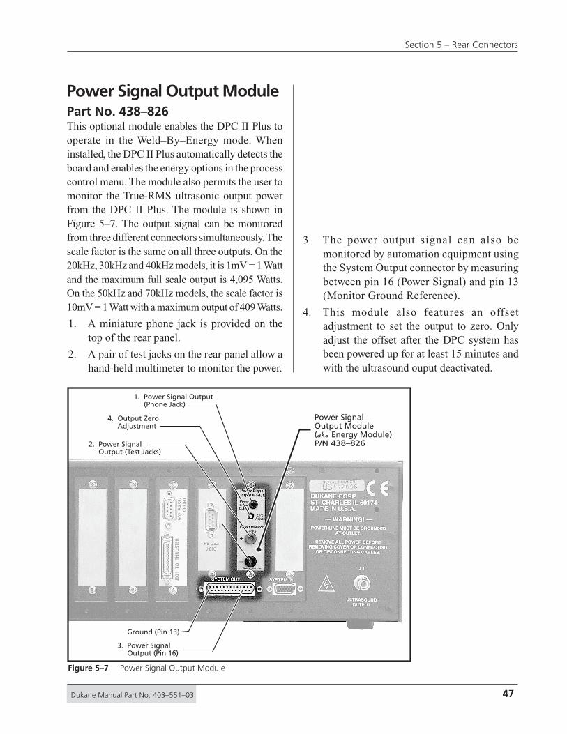
47Dukane Manual Part No. 403–551–03
Section 5 – Rear Connectors
Power Signal Output ModulePart No. 438–826This optional module enables the DPC II Plus tooperate in the Weld–By–Energy mode. Wheninstalled, the DPC II Plus automatically detects theboard and enables the energy options in the processcontrol menu. The module also permits the user tomonitor the True-RMS ultrasonic output powerfrom the DPC II Plus. The module is shown inFigure 5–7. The output signal can be monitoredfrom three different connectors simultaneously. Thescale factor is the same on all three outputs. On the20kHz, 30kHz and 40kHz models, it is 1mV = 1 Wattand the maximum full scale output is 4,095 Watts.On the 50kHz and 70kHz models, the scale factor is10mV = 1 Watt with a maximum output of 409 Watts.
1. A miniature phone jack is provided on thetop of the rear panel.
2. A pair of test jacks on the rear panel allow ahand-held multimeter to monitor the power.
3. The power output signal can also bemonitored by automation equipment usingthe System Output connector by measuringbetween pin 16 (Power Signal) and pin 13(Monitor Ground Reference).
4. This module also features an offsetadjustment to set the output to zero. Onlyadjust the offset after the DPC system hasbeen powered up for at least 15 minutes andwith the ultrasound ouput deactivated.
Power SignalOutput Module(aka Energy Module)P/N 438–826
1. Power Signal Output (Phone Jack)
3. Power Signal Output (Pin 16)
Ground (Pin 13)
4. Output Zero Adjustment
2. Power Signal Output (Test Jacks)
Figure 5–7 Power Signal Output Module

48 Dukane Manual Part No. 403–551–03
Dynamic Process Controller DPC™ II Plus – User’s Manual
Press Control ModulePart No. 110–3938This optional module enables the DPC II Plus tocontrol a Dukane Model 210, 220 or 410 press orcustom automation. The module is illustrated inFigure 5–8. The cabling hookup to a Dukane presssystem is shown in Figure 3–8.
Pin No. Type Function Signal Description
1 Input Activation Switch 1 Normally Open (N.O.) dry contact closure to ground
2 Input Activation Switch 2 Normally Open (N.O.) dry contact closure to ground
3 Input Hardware Abort Power In Normally Closed (N.C.) emergency switch contact
4 Input Software Abort Normally Open (N.O.) dry contact closure to ground
5 Ground Internal Ground Internal Ground (Gnd)
6 Ground Internal Ground Internal Ground (Gnd)
7 Ground Internal Ground Internal Ground (Gnd)
8 Input Automation Input Normally Open (N.O.) dry contact closure to ground
9 +22V DC Hardware Abort Power Out Normally Closed (N.C.) emergency switch contact
J901Thruster CableConnection
J902 PressBase CableConnector
Press ControlModuleP/N 110–3938
1
1
59
6
1836
19
Molex
DB–9
36–ContactSubminature D
Figure 5–8 Press Control Module
Table 5—V J902 Press Base Connector Pinout
Figure 5–9 PressConnector PinIdentification
NOTEThe Press Modulecannot be used simul-taneously with a MPCMulti-Probe MasterModule.

49Dukane Manual Part No. 403–551–03
Section 5 – Rear Connectors
Table 5—V on the previous page lists the pinoutand signal description for J902 which is the PressBase connection. Note that there is an automationinput on pin 8 which is electrically identical topin 8 on the System Input connector. This permitsyou to use J902 to initiate operation without havingto run a separate connection to pin 8 of the SystemInput connector. Figure 5–9 identifies the pinnumbers for both J902 and J901.
Table 5—VI below gives the pinout and signaldescription for J901 which is the 36–pin Thrusterconnector. This connector is the same type as foundon the DPC–III and DPC–IV. The cable specifiedis Part No. 200–1104 which is interchangeablewith both DPC–III and DPC–IV generators.
Pin No. Input/Output Function Signal Type
13 Input Dual Pressure SwitchNormally–Open dry contact switchclosure to ground
14 Input Ground DetectNormally–Open dry contact switchclosure to ground
15 Input Trigger SwitchNormally–Open dry contact switchclosure to ground
16 Input End Of Weld SwitchNormally–Open dry contact switchclosure to ground
Output Dual Pressure Valve Low side Mosfet driver to ground1
Output Trigger LED (–) Low side Mosfet driver to ground2
Ground +22V Return Power and Signal Ground6, 8, 10, 12,
25, 27, 28, 2930, 31, 32,34, 36
4, 19, 20,22, 24, 26
Power +22V Press Internal Power to Press
7, 9, 11, 1821, 23, 33, 35
Unused Unused Unused
Output Low side Mosfet driver to ground3 Up Valve
Output Low side Mosfet driver to ground5 Down Valve
17 InputNormally–Open dry contact switchclosure to groundPre–trigger Switch
Place Switch inWELD PRESSUREPosition Before...
Connecting DualPressure Press tothe Press ControlModule.
Table 5—VI J901 Thruster Connector Pinout
NOTEJ902 Press Base connector has multiple ground pins.The DPC–2 Plus uses pins 5, 6 & 7 for Ground.The DPC–3 uses pins 5 & 7 for Ground.The DPC–4 uses pins 6 & 7 for Ground.
To keep your custom automation circuits com-patible with DPC models, only use pin 7 for aground connection to the Press Base connector.
It should be pointed out however, that the DPC–3does have an Automation Input on pin 8.

50 Dukane Manual Part No. 403–551–03
Dynamic Process Controller DPC™ II Plus – User’s Manual
7x3 Jumper Block
6x2 Jumper7x3 Jumpe Block
er2 Jump
Figure 5–10 Press Board SH901 Cycle Activation Jumper
Cycle Activation Jumper OptionsInternal jumper SH901 on the Press Control Boardoffers options for activating a cycle.
Timer Control – DPC II Plus system defaultconfiguration.
U/S Control – DPC II system only. Not applicablefor a DPC II Plus.
Auto Control – DPC II system only. Not applicablefor a DPC II Plus.

51Dukane Manual Part No. 403–551–03
Section 5 – Rear Connectors
Multi–Probe Master ModulePart No. 110–3954This optional module enables the DPC II Plus toactivate any one of four ultrasonic probes. Eachprobe can have its own setup file which is selectedby the Setup ID# (pins 12, 13 & 14) of the HD–15System Input connector. The functions are listedin Table 5–I and 5–II. Rear panel bicolor LEDstatus indicators for each probe output illuminategreen when the probe channel is selected and redwhen the U/S is active. Both a MPC Master andSlave module are shown below in Figure 5–11.
Internal logic prevents more than one probe frombeing activated at a time or probe switching signalswhen the U/S is on. A ring-down circuit permitsswitching only when U/S output is zero. Internalfault logic senses any malfunction and deactivatesthe MPC Ready output.
The Multi–Probe Controller cannot be used with apress module. The MPC master has an extra wideback panel which blocks the press module backpanel when the MPC master module is installed.
8 Ultrasound Outputs(4 per Module)
UltrasoundInput from J1
MPC MasterModuleP/N 110–3954
MPC SlaveModuleP/N 110–3956
Multi–Probe Slave ModulePart No. 110–3956This optional module adds four additional probeselection channels to the DPC II Plus. This givesa total of eight probe channels. The slave modulecannot be used alone. It must be used with themaster module. An internal connector supplies theultrasound signal from the Master module. As withthe Master module, each output channel has abicolor LED status indicator that illuminates greenwhen the probe channel is selected and red whenthe U/S is active.
Figure 5–11 Master and Slave Multi–Probe Controller (MPC) modules
NOTEThe Ultrasound input on the MPC Mastermust be connected to the DPC Ultrasoundoutput connector (J1) with a RG62B/U coax.This is indicated as Cable 2 in Figure 3–6.

52 Dukane Manual Part No. 403–551–03
Dynamic Process Controller DPC™ II Plus – User’s Manual
Jumper Block OptionsThe DPC II Plus may be customized to your spe-cific requirements by means of internal jumpers lo-cated on the main printed circuit board. Below is alist of the jumper blocks, their default factory set-tings and their alternate positions. Figures 5–12 and5–13 on the following pages show the location ofthe jumper blocks in more detail. The factory de-fault setting is indicated by a diamond ◊ next to thedescription in Figure 5–13.
Status Driver Normal State SelectionJumper Block – SH701 (Pin 4 output on DB-25)JU701 - Normally OFF (Factory Default)JU702 - Normally ON
Status Driver SelectionJumper Block – SH702 (Pin 4 output on DB-25)JU703 - Ultrasound Active StatusJU704 - Overload Fault (Factory Default)JU705 - Over temperature FaultJU706 - System FaultJU707 - Any Fault
Automation Cycle Stop or End Of Weld SelectionJumper Block – SH704JU713 - Normally OFF (Factory Default) – Use depends upon custom automation configurationJU714 - Normally ONJU715 - Automation Stop Fault – Move jumper to this position to use Auto Stop (Figure 7–13)JU716 - Automation End of Weld (Factory Default)
Switch Debounce Filter Time Delay SelectionJumper Block – SH705JU717 - No Time Delay (used for electronic switches)JU718 - 1 msecJU719 - 10 msec (Factory Default)JU720 - 22 msec
Timer Board Enable/BypassJumper Block – SH706JU723 - Timer Board Enable (normally selected for a DPC II Plus)JU722 - Timer Board Bypass (Factory Default – used for standard DPC II)

53Dukane Manual Part No. 403–551–03
Section 5 – Rear Connectors
System Control InputsJumper Block – SH707JU724 - Non–Isolated Sink (Factory Default) – Dry
contact between input and DPC ground.JU725 - Non–Isolated Source – Dry contact be-
tween input and +22 VDC.JU726 - Isolated Source – Input can be either sink-
ing or sourcing. A signal of 5 to 24 VDCis required at the isolated inputs. The cur-rent is internally limited to 12.5mA.
JU723
JU722
JU703
JU704
TIMER BD. ENABLE
TIMER BD. BYPASS
STATUS DRIVER
NORMAL STATE
NORMALLY OFF
NORMALLY ON
JU701
JU702
NON-ISO SOURCE
NON-ISO SINK JU724
JU725
JU726ISOLATED
POWER SIGNALOUTPUT BOARD
CONTROLREMOTE
BOARD
ANY FAULT
SYS FAULT
OVERLOAD
OVERTEMP
U/S ACTIVE
JU705
JU706
JU707
STATUS DRIVERSELECTION BLOCK
JU716
JU715
JU714
JU713
AUTO END OF WELD
AUTO STOP FAULT
NORMALLY ON
NORMALLY OFF
AUTOMATION SIGNALSSELECTION BLOCK
22 mSEC
10 mSEC
1 mSEC
NO DELAY
JU720
JU719
JU718
JU717
SYS. FAULTANY FAULT
OVERLOAD
OVERTEMP
U/S ACTIVE
JU712
JU711
JU710
JU709
JU708
SELECTION BLOCKSTATUS RELAY
SELECTION BLOCK
SWITCH DEBOUNCEFILTER TIME DELAY
GAIN ADJ.OUTPUT
MONITORAMPLITUDE
MULTI-PROBECONTROLLER BOARD
MASTER
MULTI-PROBECONTROLLER BOARD
SLAVE
SELECTION BLOCKBOARDPRESS CONTROL
BOARDSTATUS RELAY
110-3606DUKANE ULTRASONICS
MADE IN USA
J709
J716 J715
J714
J711
J710
J702
J701
J712
P705
SH706
SH703 SH704
SH702
SH701
SH705
P706P704 P707P703
C717
R721
R778
R73
3
CR730R782
R74
8
R724
R771
CR
732
R745
CR721
R767
VR709
C728
R769
R711
R794VR708
C720
R710
R795
VR707
R73
0
R717
R72
9
C714
C724
RP702
C723 R779
R753
U72
8
R797
R707
CR722
R74
6
R787
CR708
CR728
R709
R777
R754
VR
701
U721
CR736
R73
1
CR706
RP703
R713
CR
735
R739
R715
R786
CR720
CR701
R77
3
R798
R732
C708
CR
711
U706
CR710
VR
711
R701
VR702
Q702
R720
C702
VR
706
C701
U705
CR723
SW701
CR719
VR
704
CR
716
C711
CR729
C713
U727
R726
CR712
U718
CR
733
R783
U702
R780
C703
R772
U715
C704
R775
R716
R72
7
R792
R73
4
CR731
CR713
R71
4
U701
R784
R72
2
R712
R791
R776
RP701
R758
U709
CR726
R793
U703
CR715R744
U723
CR718
C722
R785
P713
C716C710
R77
4
VR
703
R738
U710
P708
CR737
R737
SH707
CR725
R725
R723
CR704
U720
R790
R789
CR702
R765
R756C707
C725
U724
C719
CR705
R735
R708
R770
VR705
U722
R766
Q701
CR709
C718
U707
R759
U719
CR717
CR724
U726
R71
8
U708
C71
5
R752
R788
R70
6
R781
E701
R736
R799
U725
R74
7U717
R768
R72
8
CR
734
C709
R79
6
R71
9
C712
C721
U704
CR714
C726
CR703
CR707
C729
C727C705
C706
R749
CR727
A10 B10
A1 B1
B10A10
B1A1+
1
A10 B10
B1A1
1
2
1 39
40
41
+
41
I
AO
C EB
+
+
I
AO
+
1 4
113
A O I
101
15
1
1
1
1
IO
A
AOI
+
SYSTEM OUT SYSTEM INFigure 5–12 Card Slot, Connector and Jumper Block Locations

54 Dukane Manual Part No. 403–551–03
Dynamic Process Controller DPC™ II Plus – User’s Manual
JU723
JU722
JU703
JU704
TIMER BD. ENABLE
TIMER BD. BYPASS
STATUS DRIVERNORMAL STATE
NORMALLY OFF
NORMALLY ON
JU701
JU702
NON-ISO SOURCE
NON-ISO SINK JU724
JU725
JU726ISOLATED
POWER SIGNALOUTPUT BOARD
CONTROLREMOTE
BOARD
ANY FAULT
SYS FAULT
OVERLOAD
OVERTEMP
U/S ACTIVE
JU705
JU706
JU707
STATUS DRIVERSELECTION BLOCK
JU716
JU715
JU714
JU713
AUTO END OF WELD
AUTO STOP FAULT
NORMALLY ON
NORMALLY OFF
AUTOMATION SIGNALSSELECTION BLOCK
22 mSEC
10 mSEC
1 mSEC
NO DELAY
JU720
JU719
JU718
JU717
SYS. FAULT
ANY FAULT
OVERTEMP
U/S ACTIVE
JU712
JU711
JU710
JU709
JU708
SELECTION BLOCKSTATUS RELAY
SELECTION BLOCK
SWITCH DEBOUNCEFILTER TIME DELAY
SELECTION BLOCK
OVERLOAD
J711
J710
J712
SH706
SH703 SH704
SH702
SH701
SH705
R771
C728
R711R710
VR707
R717
C714
RP702
C723
R753
R707
CR708CR736
CR706
R715
CR710V
R70
6
U705
CR723
VR
704
C711
U718
U702
R772
R716R71
4
R712
RP701
U703
C722
SH707
CR704
R789
CR705
VR705
U707
R71
8
R70
6
C712
CR703
C729
C705
R749
1
+
I
AO
+
1
1
AOI
+
Figure 5–13 Jumper Block Detail

55Dukane Manual Part No. 403–551–03
Section 5 – Rear Connectors
Menu Structure
Dukane Corporation • • Ultrasonics Division
SECTION 6
Process Setup ............................................... 57Process Control ............................................. 58Process Limits ............................................... 60Utilities ......................................................... 61
• Process Setup
• Process Control
• Process Limits
• Utilities

56 Dukane Manual Part No. 403–551–03
Dynamic Process Controller DPC™ II Plus – User’s Manual
This page intentionally left blank

57Dukane Manual Part No. 403–551–03
Section 6 – Menu Structure
Process Setup MenuThis section deals with the overall menu structure.Each setup menu is later discussed in detail in itsown section. Each time the DPC II Plus is poweredup, the processor scans the system to determinewhich modules are installed and if a hand probe isconnected. It first displays which version of theDPC firmware is installed as shown in Figure 6–1.
DUKANE DPC II+ v1.10(c)2002 Dukane Corp.All Rights Reserved
After a few seconds, the screen displays the weldingmode and installed modules. Depending upon yourconfiguration, your screen may display HAND PROBEDETECTED, AUTO PROBE DETECTED, MPC PROBE DE-TECTED, ECONOMY PRESS DETECTED. or PRESS BOARDDETECTED. This is shown in Figure 6–2.
AUTO MODE
PRESS BOARD DETECTED
Then the screen then displays the operate pagewhich contains the measured values from the lastweld cycle as shown in Figure 6–3. If the PartsCounter (covered in detail in Section 9 –Utilities)is active, the count is displayed in the upper left–hand corner in place of the dashes (– – – – –). The# sign and the digit after the dashes indicate whichsetup file is active. There are eight setup files avail-able. Setup files are covered in Select Setup ofSection 9 – Utilities Menu.
– – – – – #1 TIME ENERGY P1 0.000 0 P2 0.000 0TOTAL 0.000 0
Press the MODE key once to switch from theOperate mode to the Setup mode and display theProcess Setup menu shown below in Figure 6–4.
PROCESS SETUPPROCESS CONTROLPROCESS LIMITSUTILITIES
Figure 6–2 DPC II Plus Configuration Menu
Figure 6–1 DPC II Plus Startup Menu
Figure 6–3 DPC II Plus Weld Cycle Display
Figure 6–4 DPC II Plus Process Setup Menu

58 Dukane Manual Part No. 403–551–03
Dynamic Process Controller DPC™ II Plus – User’s Manual
Process Control, Limit Definition or Utilitiesmenu. Press the ENTER key to activate the selectedmenu. The Process Control Menu selects the trig-ger method, the welding mode and sets the valuesfor the welding parameters. This menu’s structureis the most complex of the three. However, sincethe DPC II Plus reconfigures the user interface tobe consistent with the installed modules, only therelevant portion of the menu structure is displayed.The flow chart for the Process Control menu isshown in Figure 6–6. The menu structure buildslogically upon itself starting with the Hand Probeon the right side and progressing with more op-tions towards the Press menu on the left. ProcessControl is discussed in detail in Section 7.
The main structure of the Process Setup menu isshown in Figure 6–5. You can press the MODE keyor the CANCEL key twice at any time to return to theProcess Setup menu. The MODE key toggles betweenthe Weld Cycle data (Operate mode) and ProcessSetup menu (Setup mode) each time it is pressed. Pro-cess Setup is the root menu to select all subsequentsub menus. The Press menu option is only present if aPress Control Module is installed. The energy valueis only displayed if a Power Output module is installed.The Process Control menu sets the welding param-eters. Limit Definition menu sets the bounds for sus-pect parts and bad parts. Utilities menu enables youto save, copy and erase setup files, count parts whichare out of limit and configure status outputs.
Process Control MenuBy pressing the up–arrow and down–arrow keysyou can navigate the triangle pointer to select the
SECTION 9
SECTION 8
SECTION 7
Only present ifPress Control Moduleis installed
From many levelsdown in the menu
Setup File currently being used
Only present ifPower Output Moduleis installed
Part Countappears here
OPERATEMode
SETUPMode
TRIGGER METHODPRESSTIMED PROBEUNTIMED PROBE
PROCESS SETUPPROCESS CONTROLPROCESS LIMITSUTILITIES
LIMIT DEFINITIONSUSPECT LIMITSBAD LIMITS
UTILITIESSETUP UTILITIESPART COUNTSTATUS OUTPUTS
----- #1 TIME ENERGY P1 0.000 0 P2 0.000 0TOTAL 0.000 0
MODE MODE
MODE
CANCEL CANCEL
ENTER
Figure 6–5 Process Setup Main Menu Structure

59Dukane Manual Part No. 403–551–03
Section 6 – Menu Structure
TRIGGER METHODPROCESSCONTROL
PROCESSSETUP
PRESSTIMED PROBE
MANUAL
INITIATEMODE
AUTO
MOMENTARY MAINTAINED
TRIGGER TYPE
ENABLE or DISABLE
AUTO STOP
WELDMODE
1 1
2 2
HOLDTIME
PROCESS CONTROLAFTER–BURST
WELDMETHOD
HOLDTIME
PROCESS CONTROL
AFTER–BURST
RTWRTW
RTW
Step 1 Step 2Step 3
TIMEDHANDPROBE
TIMEDMPCPROBE
TIMEDAUTOPROBE
UNTIMEDAUTOPROBE
UNTIMEDMPCPROBE
UNTIMEDHANDPROBE
Step 1 Step 2Step 3
RTW = READY TO WELD
RTW = READY TO WELD
TIMED UNTIMED TIMED UNTIMED TIMED UNTIMED
AUTOPROBE
MPCPROBE
HANDPROBE
AUTO STOP
ENABLE DISABLE
HEAD UP ONAUTO STOP
WELD MODEDUAL
PRESSURESINGLE
PRESSURE
WELD METHOD
TIME ENERGY GND.DETECT
WELD METHOD
TIME ENERGY GND.DETECT
WELD METHOD
TIME ENERGY GND.DETECT
RTWRTW
WELD METHOD
TIME ENERGY
PRESSURE 1TIME ENERGY
PRESSURE 2TIME ENERGY
ENABLE DISABLE
UNTIMED PROBE
DUALPRESSUREPRESS
SINGLEPRESSUREPRESS
Figure 6–6 Process Control Menu Flowchart

60 Dukane Manual Part No. 403–551–03
Dynamic Process Controller DPC™ II Plus – User’s Manual
Limit Definition MenuThe Limit Definition menu has two classes ofsettings. The first class is the suspect limits andthe second class is for bad part limits. Whenapplicable, choices for time, energy, total timeand total energy are available. A simplified flowchart for the Limit Definition menu is shown inFigure 6–7. Although not indicated in this draw-ing, both upper and lower bounds can be set foreach limit. The Limit Definition menu is cov-ered in greater detail in Section 8.
Total LimitsAvailable Only withPress Controller inDual Pressure Mode
LIMIT DEFINITIONSUSPECTBAD
TIME
ENERGY
TOTAL TIME
TOTAL ENERGY
PROCESSLIMITS
WELDTIME P2
WELDTIME P1
PROCESSLIMITS
WELDENERGY P2
WELDENERGY P1
TOTALWELD TIME
TOTALWELD ENERGY
LIMITS
PROCESSLIMITS
PROCESSSETUP
Figure 6–7 Limit Definition Menu Flowchart

61Dukane Manual Part No. 403–551–03
Section 6 – Menu Structure
Utilities MenuThe Utilities menu has four different sections. Thefirst section handles setup file operations. The sec-ond section accesses the parts count functions. Thethird section configures the status output. Thefourth section allows the operator to cycle the pressoff line. A simplified flow chart for the Utilitiesmenu is shown in Figure 6–8 and is covered ingreater detail in Section 9.
UTILITIESSETUP UTILITIES
ERASECURRENT
SETUP
ERASEALL
SETUPS
STATUSOUTPUTS
ERASESETUPS
LOCAL REMOTE
SETUPTYPEPULSEDMAINTAINED
SETUPUTILITIES
ERASESETUPS
COPYSETUP
SELECTSETUP
PARTCOUNT
PRESETPART
COUNT
COUNTBAD
PARTS
RESETPART
COUNT
PART COUNT
STATUS OUTPUTS
CYCLE PRESS OFF LINE
UTILITIES
PROCESSSETUP
Figure 6–8 Utilities Menu Flowchart

62 Dukane Manual Part No. 403–551–03
Dynamic Process Controller DPC™ II Plus – User’s Manual
This page intentionally left blank

63Dukane Manual Part No. 403–551–03
Section 6 – Menu Structure
Process Control Menu
Dukane Corporation • • Ultrasonics Division
SECTION 7
Hand Probe .................................................. 65Untimed Hand Probe ............................................66Timed Hand Probe ...............................................66Timed Hand Probe – Energy .................................67
MPC Probe ................................................... 68Auto Stop Option.................................................68Untimed MPC Probe – Probe Delay.......................68Weld Method – Time ...........................................69Weld Method – Energy ........................................70Weld Method – Ground Detect ............................70
Auto Probe ................................................... 71Auto Stop Option.................................................72Untimed Auto Probe – Delay ................................73Timed Auto Probe – Weld Method .......................73HoldTime .............................................................73Afterburst ............................................................73
Press Mode ................................................... 75Initiate Mode .......................................................76Auto Stop ............................................................76Head Up On Auto Stop ........................................76Trigger Type..........................................................76Single/Dual Pressure Mode ...................................76
Press Mode Example ..................................... 77Hot Keys ....................................................... 81Process Control Recap................................... 82
• Hand Probe
• MPC Probe
• Auto Probe
• Press Mode
• Hot Keys

64 Dukane Manual Part No. 403–551–03
Dynamic Process Controller DPC™ II Plus – User’s Manual
This page intentionally left blank
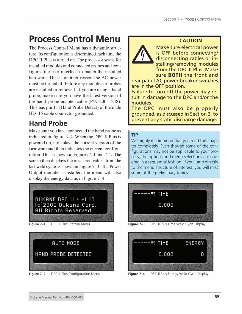
65Dukane Manual Part No. 403–551–03
Section 7 – Process Control Menu
Process Control MenuThe Process Control Menu has a dynamic struc-ture. Its configuration is determined each time theDPC II Plus is turned on. The processor scans forinstalled modules and connected probes and con-figures the user interface to match the installedhardware. This is another reason the AC powermust be turned off before any modules or probesare installed or removed. If you are using a handprobe, make sure you have the latest version ofthe hand–probe adapter cable (P/N 200–1248).This has pin 11 (Hand Probe Detect) of the maleHD–15 cable connector grounded.
Hand ProbeMake sure you have connected the hand probe asindicated in Figure 3–4. When the DPC II Plus ispowered up, it displays the current version of thefirmware and then indicates the current configu-ration. This is shown in Figures 7–1 and 7–2. Thescreen then displays the measured values from thelast weld cycle as shown in Figure 7–3. If a PowerOutput module is installed, the menu will alsodisplay the energy data as in Figure 7–4.
DUKANE DPC II + v1.10(c)2002 Dukane Corp.All Rights Reserved
AUTO MODE
HAND PROBE DETECTED
–––––#1 TIME
0.000
– – – – –#1 TIME ENERGY
0.000 0
Figure 7–2 DPC II Plus Configuration Menu
Figure 7–1 DPC II Plus Startup Menu Figure 7–3 DPC II Plus Time Weld Cycle Display
Figure 7–4 DPC II Plus Energy Weld Cycle Display
TIPWe highly recommend that you read this chap-ter completely. Even though some of the con-figurations may not be applicable to your pro-cess, the options and menu selections are cov-ered in a sequential fashion. If you jump directlyto the menu structure of interest, you will misssome of the preliminary topics.
CAUTIONMake sure electrical poweris OFF before connecting/disconnecting cables or in-stalling/removing modulesfrom the DPC II Plus. Makesure BOTH the front and
rear panel AC power breaker switchesare in the OFF position.Failure to turn off the power may re-sult in damage to the DPC and/or themodules.The DPC must also be properlygrounded, as discussed in Section 3, toprevent any static discharge damage.
�

66 Dukane Manual Part No. 403–551–03
Dynamic Process Controller DPC™ II Plus – User’s Manual
Press the MODE key to display the Process Setupmenu. In Process Setup, the cursor should be point-ing to Process Control as shown in Figure 7–5. Ifit is not, press the up–arrow and down–arrow keyto navigate the triangle pointer to select ProcessControl. Press the ENTER key to activate the se-lected menu.
Since the DPC II Plus reconfigures the user inter-face to be consistent with the installed modules,only the portion of the menu structure relating tohand probe operation is displayed. The only op-tion for the Process Control screen is the TriggerMethod which is shown in Figure 7–6.
The flow chart for the Process Control menu witha hand probe connected is shown in Figure 7–7. Ifyou do not have a Power Output module installed,the Energy Weld Method will not be displayed.
Untimed Hand ProbeUntimed Hand Probe operation has no parametersto enter. The generator is triggered whenever thehand probe trigger is engaged and continues untilthe trigger is released. Press ENTER and you areready to weld (RTW).
Timed Hand ProbeIn Timed Hand Probe mode, the welding stops when-ever the trigger is released or the specified weld time
PROCESS SETUPPROCESS CONTROLPROCESS LIMITSUTILITIES
TRIGGER METHODTIMED HAND PROBEUNTIMED HAND PROBE
TRIGGER METHODTIMED HAND PROBE
TIMEDHANDPROBE
UNTIMEDHANDPROBE
RTW
RTW
WELD METHOD
TIME ENERGY
UNTIMED HAND PROBE
ENTER
ENTER
ENTER
ENTER
ENTER
Tw
eld
Ew
eld
Tm
ax
HandProbeTriggerSwitch
HandProbeTriggerSwitch
Figure 7–11
Figure 7–10
Figure 7–8
Figure 7–9
Figure 7–6
Maximum EweldMinimum Eweld
= 12,000 Joules= 1 Joule*
Maximum TmaxMinimum Tmax
= 30.000 Seconds= 0.001 Second*
Maximum TweldMinimum Tweld
= 29.999 Seconds= 0.001 Second*
* These values can be set to zero, but will not produce any output. The values listed represent the resolution and are the smallest values that will produce any output signal.
Tw
eld
RTW = Ready To Weld
LEGEND
= Front Panel ENTER Key (Section 4.3 – Menu Keys)
ENTER
= Parameter Value Entry T = Time E = Energy
Figure 7–7 Hand Probe Flow Chart
Figure 7–5 Process Setup Menu
Figure 7–6 Process Control Trigger Method Menu

67Dukane Manual Part No. 403–551–03
Section 7 – Process Control Menu
is reached, whichever comes first. Press ENTER andthe data entry screen appears as shown in Figure7–9. If a Power Output module is installed, then aWeld Method screen shown in Figure 7–8 is dis-played first. Press the ENTER key to display the weldtime data entry. If a Power Output module is notinstalled, there is only one choice and the WeldMethod screen is bypassed. Timed Hand Probe op-eration requires the weld time to be entered. Use theLeft and Right arrow keys to move to the desireddigit position and the Up and Down arrow keys toincrement or decrement the value. When the desiredvalue is displayed, press ENTER for the next menuuntil all the required values have been entered.
Timed Hand Probe – EnergyIf a Power Output module is installed, you can alsochoose the Weld By Energy method. From theWeld Method screen shown in Figure 7–8, movethe cursor down so it points to Weld By Energyand press the ENTER key.
To weld using the Energy Method, you first enterthe desired welding energy, This data entry screenis shown in Figure 7–10. Enter the desired weld-ing energy and press ENTER . Now enter the maxi-mum weld time as shown in Figures 7–11. PressENTER to complete the process. You will return tothe Process Setup menu (Figure 7–5).
WELD METHODWELD BY TIMEWELD BY ENERGY
WELD ENERGY
75 J
MAX WELD TIME
1.000 SEC
WELD TIME
0.500 SEC
Figure 7–9 Hand Probe Weld Time
Figure 7–10 Hand Probe Weld Energy
Figure 7–11 Hand Probe Max Weld Time
Figure 7–8 Hand Probe Weld Method
NOTEThe flowchart beginning with powerup to theProcess Setup menu (Figure 7–5) and the TriggerMethod screen (Figure 7–6) is shown in Figure6–5. A portion of the drawing is repeated here.
Only present ifPower Output Moduleis installed
TRIGGER METHODTIMED PROBEUNTIMED PROBE
PROCESS SETUPPROCESS CONTROLPROCESS LIMITSUTILITIES
----- #1 TIME ENERGY
0.000 0
MODE MODE
MODE
CANCEL CANCEL
ENTER
Figure 7–3 and 7–4
Figure 7–5
Figure 7–6
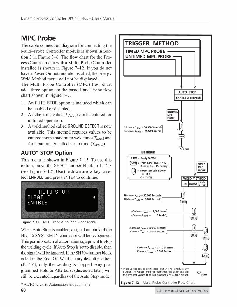
68 Dukane Manual Part No. 403–551–03
Dynamic Process Controller DPC™ II Plus – User’s Manual
MPC ProbeThe cable connection diagram for connecting theMulti–Probe Controller module is shown in Sec-tion 3 in Figure 3–6. The flow chart for the Pro-cess Control menu with a Multi–Probe Controllerinstalled is shown in Figure 7–12. If you do nothave a Power Output module installed, the EnergyWeld Method menu will not be displayed.The Multi–Probe Controller (MPC) flow chartadds three options to the basic Hand Probe flowchart shown in Figure 7–7.
1. An AUTO STOP option is included which canbe enabled or disabled.
2. A delay time value (Tdelay) can be entered foruntimed operation.
3. A weld method called GROUND DETECT is nowavailable. This method requires values to beentered for the maximum weld time (Tmax) andfor a parameter called scrub time (Tscrub).
AUTO* STOP OptionThis menu is shown in Figure 7–13. To use thisoption, move the SH704 jumper block to JU715(see Figure 5–12). Use the down arrow key to se-lect ENABLE and press ENTER to continue.
When Auto Stop is enabled, a signal on pin 9 of theHD–15 SYSTEM IN connector will be recognized.This permits external automation equipment to stopthe welding cycle. If Auto Stop is set to disable, thenthe signal will be ignored. If the SH704 jumper blockis left in the End–Of–Weld factory default position(JU716), only the welding is stopped. Any pro-grammed Hold or Afterburst (discussed later) willstill be executed regardless of the Auto Stop mode.
AUTO STOPDISABLEENABLE
UNTIMED MPC PROBE
ENABLE or DISABLE
AUTO STOP
TIMEDMPCPROBE
UNTIMEDMPCPROBE
WELD METHOD
TIME ENERGY GND.DETECT
TRIGGER METHODTIMED MPC PROBE
RTW
RTW
ENTER
ENTER
ENTERENTER
ENTER
ENTER
Tw
eld
Ew
eld
Tm
ax
Tm
axT
scru
b
Tde
lay
Tw
eld
RTW = Ready To Weld
LEGEND
= Front Panel ENTER Key (Section 4.3 – Menu Keys)
ENTER
= Parameter Value Entry T = Time E = Energy
Maximum EweldMinimum Eweld
= 12,000 Joules= 1 Joule*
Maximum TmaxMinimum Tmax
= 30.000 Seconds= 0.001 Second*
Maximum TweldMinimum Tweld
= 30.000 Seconds= 0.001 Second*
Maximum TdelayMinimum Tdelay
= 30.000 Seconds= 0.000 Second
Maximum TscrubMinimum Tscrub
= 0.150 Seconds= 0.001 Second
* These values can be set to zero, but will not produce any output. The values listed represent the resolution and are the smallest values that will produce any output signal.
Figure 7–12 Multi–Probe Controller Flow Chart
Figure 7–13 MPC Probe Auto Stop Mode Menu
* AUTO refers to Automation not automatic

69Dukane Manual Part No. 403–551–03
Section 7 – Process Control Menu
Untimed MPC Probe – Probe DelayThe probe delay time value for untimed operationis shown in Figure 7–14. This parameter is typi-cally used in a single auto probe configurationwhich is covered later in this section. For MPCuntimed operation, the suggested value for thedelay time is 0.000 second.
Weld Method – TimeFor the Time welding method, an ultrasonic sig-nal is generated for a specific time once triggered.After the AUTO STOP menu, the WELD METHODmenu is displayed. This is shown in Figure 7–15.
To weld by time, select WELD BY TIME using theUp and Down arrow keys and press the ENTERkey. The weld time data entry screen appears asshown in Figure 7–16.
PROBE DELAY
0.000 SEC
WELD METHODWELD BY TIMEWELD BY ENERGYGROUND DETECT
WELD TIME
0.450 SEC
Use the Left and Right arrow keys to move thecursor to the desired digit position and the Up andDown arrow keys to increment or decrement thevalue. When the desired value is displayed, pressENTER to return to the main PROCESS SETUPmenu shown in Figure 7–5.
Figure 7–14 MPC Probe Time Delay
Figure 7–15 MPC Probe Weld Method Selection Menu
Figure 7–16 MPC Probe Weld Time
NOTEThe RTW symbol (RTW = Ready To Weld) at thebottom of each logical branch in theflowchart,means the DPC II Plus is logicallycapable of being triggered to generate anultrasonic output. This is indicated on the displayscreen by the presence of the PROCESS SETUPmenu shown in Figure 7–5.
CAUTIONIf the AUTO STOP optionis set to ENABLE, youmust supply the IsolatedAutomation Stop inputsignal to pin 9 of the HD–15 SYSTEM INPUT con-
nector (see Table 5—I). The SH707jumper block (see Figure 5–11) de-termines whether the the signal isisolated or non–isolated and sourc-ing or sinking.
�
NON-ISO SOURCE
NON-ISO SINK JU724
JU725
JU726ISOLATED
R771 C723
R772
C722
SH707

70 Dukane Manual Part No. 403–551–03
Dynamic Process Controller DPC™ II Plus – User’s Manual
Weld Method – Energy
If a Power Output module is installed, you canchoose the Energy Welding method. The decisionmenu for choosing the Weld Method was shownin Figure 7–15. Use the down arrow key to movethe cursor next to WELD BY ENERGY selectionand press the ENTER key. To setup the Energy weldmethod, you must first enter the desired weldingenergy (see Figure 7–17).
Press ENTER and the maximum weld time dataentry screen is displayed as shown in Figure 7–18. This is the time limit on the welding processif the specified energy has not been reached.Enter a value which permits the desired weldenergy to be reached.Press the ENTER keyto return home to theProcess Setup menu.
Weld Method –Ground Detect
The GROUND DETECTwelding method isavailable in both MPCProbe and Auto Probeconfigurations. Inground detect mode,the ultrasonic signal isinitiated when the op-erate input is triggeredand terminated whenthe horn touches themetal fixture duringthe welding cycle. Forthe ground detect fea-
WELD ENERGY
125 J
MAX WELD TIME
1.250 SEC
Figure 7–17 MPC Probe Weld Energy
Figure 7–18 MPC Probe Maximum Weld Time
DEFINITIONPower is defined as Energy per unit of Time(i.e. how fast energy is produced or consumed).
Energy is defined as the capacity to do Work.The release of energy does work, and in do-ing work on something, adds energy to it.Work and energy are equivalent concepts. TheWeld–By–Energy mode measures energy inunits of Joules. By definition, a Watt (power) isone Joule (energy) per Second (time). Thereforea Joule is equivalent to one Watt–Second.
Horn
Fixture
Base
PlasticInsulatingSheet
PlasticWasher
GroundDetectWire
The horn is grounded and acts as a switch closure when it contacts the fixture.
Connect a wire from the fixture to pin 14 of J901
Install a plastic insulator between the fixture and the base.
Use plastic insulating wash-ers between the bolts and fixture. Center the washers so the bolts do not touch the inside of the fixture mounting holes
Figure 7–19 Ground Detect Fixture Isolation

71Dukane Manual Part No. 403–551–03
Section 7 – Process Control Menu
ture to function properly, the fixture must be elec-trically isolated from the horn support and base asshown in Figure 7–19. The horn is grounded andacts as a switch closure when it contacts the fix-ture. The ground detection is a current limited +5VDC signal on pin 14 of J901 which is the Thrusterconnector on the Press Control module. Grounddetect is normally used with a press system.
The MPC module cannot be used simultaneouslywith a Press Control module. If the ground–de-tect function is needed with a MPC configuration,connect the ground detect wire from the isolatedfixture to the Iso Auto Stop (pin 9) on the SystemInput HD–15 connector. This is a current limited+22V DC signal. Move the SH704 jumper blockto JU715 and refer to the discussion of the AutoStop option under Figure 7–13, since pin 9 is usedto stop the weld in both cases.
Max Weld Time
Maximum Weld Time is the value at which the weld-ing process terminates regardless of whether theground detect signal or scrub process has been ac-tivated. The data entry screen for maximum weldtime looks the same as the screens shown in Fig-ures 7–11 and 7–18. Set the maximum weld timeto a value greater than the time required to com-plete the welding cycle including the scrub time.
SCRUB TIME
0.075 SEC
Scrub Time
Scrub Time is an extension of the welding cyclewhich is generated when the ground detect signalwould normally end the weld cycle. This is typi-cally used in cutting operations. Often the horncuts through the material at a single point. Thisactivates the ground detect to end the weld cycle.But the cut may not be complete, and the addi-tional scrub time keeps the ultrasound signal onto complete the cut. The data entry screen for scrubtime is shown in Figure 7–20. The maximum al-lowable time value is 0.150 seconds.
Figure 7–20 Ground Detect Scrub Time Data Entry
NOTEThe word AUTO in the menu options is shortfor Automation not automatic. Any menu thatcontains the word AUTO means the DPC II Pluswill require an external signal(s) from customautomation equipment for correct operation.

72 Dukane Manual Part No. 403–551–03
Dynamic Process Controller DPC™ II Plus – User’s Manual
AUTO ProbeThe cable connection diagram for connecting anautomated probe or an automated thruster is shownin Section 3 in Figures 3–5 and 3–7. The flow chartfor the Process Control menu using Auto Probe isshown in Figure 7–21. If you do not have a PowerOutput module installed, the Energy Weld Methodmenu will not be displayed.
The Auto Probe Setup logic adds a Process Con-trol menu before the Weld Method decision menu.Compare the flowchart in Figure 7–21 to the pre-vious MPC flowchart in Figure 7–12. The Pro-cess Control menu offers two additional settingsto control the welding process. After the normalWeld Method is programmed, Hold time andAfterburst settings are available.
1. The HOLD TIME parameter (Thold) determinesthe length of time the probe is held in contactwith the parts after the welding cycle hasstopped. Holding permits the material to so-lidify under pressure before the head retracts.
2. In some applications, the material beingwelded can stick to the horn as it retracts. Ashort burst of ultrasonic energy calledAFTERBURST prevents this. This operation isdefined by two values. The delay after the startof the upstroke before the burst starts (Tdelay)and the duration of the burst signal (Tburst).The maximum value of both of these param-eters is 0.999 second.
AUTO STOP OptionThe Auto Stop option is shown in Figure 7–13. It isdesigned for use with automation equipment and isavailable in both the Timed and Untimed Auto ProbeTrigger Method. To use this option, move the SH704jumper block to JU715 (see Figure 5–12). If AutoStop is enabled, then a stop signal on pin 9 of theHD–15 SYSTEM IN connector will be recognized.This permits external automation equipment to stopthe welding cycle. If Auto Stop is set to disable,then a signal on pin 9 will be ignored.
Tw
eld
RTW = Ready To Weld
LEGEND
= Front Panel ENTER Key (Section 4.3 – Menu Keys)ENTER
= Parameter Value Entry T = Time E = Energy
WELDMETHOD
HOLDTIME
PROCESS CONTROL
AFTER–BURST
RTW
RTW
TIMEDAUTOPROBE
UNTIMEDAUTOPROBE
Step 1 Step 2Step 3
WELD METHOD
TIME ENERGY GND.DETECT
UNTIMED AUTO PROBE
TRIGGER METHODTIMED AUTO PROBE
ENABLE or DISABLE
AUTO STOP
ENTER
ENTER
ENTER
ENTERENTER
ENTER
ENTER
ENTER
ENTER
Tde
lay
Tho
ld
Tde
lay
Tbu
rst
Tw
eld
Ew
eld
Tm
ax
Tm
axT
scru
b
E/D
ENTER
Enable/Disable
Maximum EweldMinimum Eweld
= 12,000 Joules= 1 Joule*
Maximum TmaxMinimum Tmax
= 30.000 Seconds= 0.001 Second*
Maximum TweldMinimum Tweld
= 30.000 Seconds= 0.001 Second*
Maximum TholdMinimum Thold
= 30.000 Seconds= 0.001 Second*
Maximum TdelayMinimum Tdelay
= 30.000 Seconds= 0.000 Second
Maximum TdelayMinimum Tdelay
= 0.999 Second= 0.000 Second
Maximum TburstMinimum Tburst
= 0.999 Second= 0.001 Second*
Maximum TscrubMinimum Tscrub
= 0.150 Seconds= 0.001 Second*
* These values can be set to zero, but will not produce any output. The values listed represent the resolution and are the smallest values that will produce any output signal.
Figure 7–21 Auto Probe Setup Flow Chart

73Dukane Manual Part No. 403–551–03
Section 7 – Process Control Menu
Untimed Auto Probe – DelayThe generator is triggered by external automa-tion equipment. The automation control providesthe ultrasound start and stop signal. In certainoperations, a delay may be required to allow theclamping head(s) to fully engage before startingthe ultrasound. The probe delay time menu foruntimed operation was shown previously in Fig-ure 7–14. This parameter sets the post–triggerdelay. The maximum value which can be enteredis 30.000 seconds. The minimum value for theDelay Time is 0.000 second which effectively dis-ables any delay.
Process Control – Weld MethodIn Timed Auto Probe mode, after choosing the AutoStop option and pressing ENTER, the next menudisplayed is titled Process Control as shown in Fig-ure 7–22. The Process Control Menu includes theWeld Method and adds two more menu screens.Refer back to the Hand Probe and MPC Probe sec-tions for information on the Time, Energy andGround Detect Welding method menus.
Process Control – Hold TimeAfter the Weld Method has been chosen and pa-rameter values entered, the menu flow returns backto Process Control but with Hold Time automati-cally selected. This is shown below in Figure 7–23.
PROCESS CONTROLWELD METHODHOLD TIMEAFTERBURST
PROCESS CONTROLWELD METHODHOLD TIMEAFTERBURST
The data entry screen for Hold Time is shown inFigure 7–24. The maximum allowable holdingtime is 30.000 seconds.
Process Control – AfterburstAfter the hold time value has been entered, pressthe ENTER key to return back to the Process Con-trol menu. Afterburst is now automatically selectedas shown in Figure 7–25.
Press the ENTER key to select the final set ofwelding parameters. A decision screen appearsto either enable or bypass the afterburst setting.To bypass the afterburst option, select DISABLEand press the ENTER key. You are then returnedback to the Process Control menu (Figure 7–22).Press the CANCEL key once or the MODE keytwice to return to the root Process Setup menu(Figure 7–29).
HOLD TIME
1.200 SEC
PROCESS CONTROLWELD METHODHOLD TIMEAFTERBURST
AFTERBURSTDISABLEENABLE
Figure 7–22 Process Control Weld Method Menu
Figure 7–24 Auto Probe Hold Time Data Entry Screen
Figure 7–25 Auto Probe Process Control Afterburst Menu
Figure 7–26 Auto Probe Afterburst Enable MenuFigure 7–23 Auto Probe Process Control Hold Time Menu
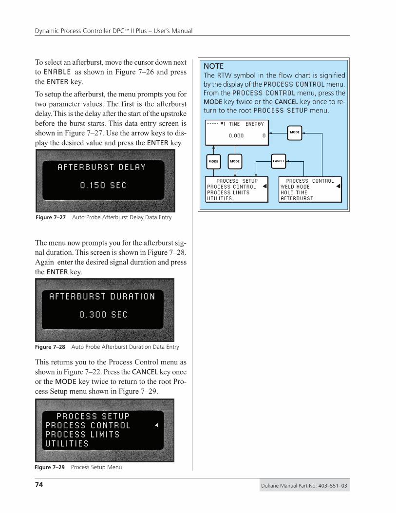
74 Dukane Manual Part No. 403–551–03
Dynamic Process Controller DPC™ II Plus – User’s Manual
To select an afterburst, move the cursor down nextto ENABLE as shown in Figure 7–26 and pressthe ENTER key.
To setup the afterburst, the menu prompts you fortwo parameter values. The first is the afterburstdelay. This is the delay after the start of the upstrokebefore the burst starts. This data entry screen isshown in Figure 7–27. Use the arrow keys to dis-play the desired value and press the ENTER key.
The menu now prompts you for the afterburst sig-nal duration. This screen is shown in Figure 7–28.Again enter the desired signal duration and pressthe ENTER key.
This returns you to the Process Control menu asshown in Figure 7–22. Press the CANCEL key onceor the MODE key twice to return to the root Pro-cess Setup menu shown in Figure 7–29.
AFTERBURST DELAY
0.150 SEC
AFTERBURST DURATION
0.300 SEC
PROCESS SETUPPROCESS CONTROLPROCESS LIMITSUTILITIES
Figure 7–27 Auto Probe Afterburst Delay Data Entry
Figure 7–28 Auto Probe Afterburst Duration Data Entry
Figure 7–29 Process Setup Menu
NOTEThe RTW symbol in the flow chart is signifiedby the display of the PROCESS CONTROL menu.From the PROCESS CONTROL menu, press theMODE key twice or the CANCEL key once to re-turn to the root PROCESS SETUP menu.
PROCESS SETUPPROCESS CONTROLPROCESS LIMITSUTILITIES
PROCESS CONTROLWELD MODEHOLD TIMEAFTERBURST
----- #1 TIME ENERGY
0.000 0
MODE MODE
MODE
CANCEL

75Dukane Manual Part No. 403–551–03
Section 7 – Process Control Menu
PRESS ModeThe cable connection diagram for connecting aDPC II Plus to a Dukane press is shown in Sec-tion 3 in Figures 3–8. The flow chart for the Pro-cess Control menu is shown in Figure 7–30. If aPress Control module is not installed, this menuwill not be displayed. If you do not have a PowerOutput module installed, the Energy Weld Methodmenu options will not appear either.
The Press Setup logic features two areas of enhance-ment over the Auto Probe logic. The PRESS TRIG-GER METHOD has three additional control optionsin the Auto Stop logical branch (the Auto Probetrigger methods are still available). The WELDMODE menu is also expanded and offers a choiceof SINGLE PRESSURE or DUAL PRESSURE mode.Compare the flowchart in Figure 7–30 to the previ-ous Auto Probe flowchart in Figure 7–21.
1. The TRIGGER METHOD – PRESS mode has anINITIATE MODE menu preceding Auto Stop.The MANUAL mode is the recommended set-ting. This permits the dual palm switches onthe press base to initiate the operate sequence.
2. If ENABLE was selected in the AUTO STOPmenu, the HEAD UP ON AUTO STOP menu isdisplayed. Auto Stop has been covered previ-ously under MPC Probe and AUTO Probe. TheHEAD UP menu determines whether the presshead remains at its last position or retracts whenan external Auto Stop signal is detected.
PRESS
MANUAL
INITIATEMODE
AUTO
MOMENTARY MAINTAINED
TRIGGER TYPE
WELDMODE
1 1
2 2
HOLDTIME
PROCESS CONTROLAFTER–BURST
Step 1
TimedAuto
ProbeBypasses
Single/DualPressure
Mode
Press TriggerMethod Only
Step 2Step 3
RTW
AUTO STOP
ENABLE DISABLE
HEAD UP ONAUTO STOP
WELD MODEDUAL
PRESSURESINGLE
PRESSURE
WELD METHOD
TIME ENERGY GND.DETECT
PRESSURE 1TIME ENERGY
PRESSURE 2TIME ENERGY
ENABLE DISABLE
UNTIMED AUTO PROBE
TRIGGER METHOD
TIMED AUTO PROBE
ENABLE or DISABLE
AUTO STOP
RTW
E/D
ENTER
Enable/Disable
ENTER
ENTER
ENTER
ENTER
ENTER
ENTER
ENTER ENTER
ENTER ENTER
ENTER
ENTER ENTER
ENTER
ENTER
ENTERENTER
ENTER
ENTER
ENTER
ENTER
ENTER
ENTER
ENTER
ENTER
ENTERENTER
ENTER
ENTER
Tho
ld
Tw
eld
T1 w
eld
Ew
eld
E1 w
eld
E2 w
eld
Tm
ax
T1 m
axT
2 max
Tm
axT
scru
b
T2 w
eld
Tde
lay
Tbu
rst
Tde
lay
SINGLEPRESSUREPRESS DUAL
PRESSUREPRESS
Figure 7–30 Press/Auto Probe Setup Flow Chart
NOTEThe symbol legend for the Press Mode flow chartis the same as the other flow charts. It is re-peated here for your convenience.
Tw
eld
RTW = Ready To Weld
LEGEND
= Front Panel ENTER Key (Section 4.3 – Menu Keys)ENTER
= Parameter Value Entry T = Time E = Energy

76 Dukane Manual Part No. 403–551–03
Dynamic Process Controller DPC™ II Plus – User’s Manual
3. If DISABLE was selected in the AUTO STOPmenu, the TRIGGER TYPE menu is displayednext. This selects whether the trigger whichinitiates the weld cycle is momentary or mustbe maintained throughout the weld cycle.
4. The SINGLE PRESSURE mode follows thesame programming sequence as Weld Methodin the previous Timed Auto Probe. The DUALPRESSURE mode eliminates ground detect forobvious reasons and allows welding by Timeor Energy at both pressure level settings.
Initiate ModeWhen using a press, the usual choice is to selectMANUAL for the Initiate Mode. This permits thedual palm switches to initiate the operate sequence.If AUTO mode is selected, then an external initiatesignal must be supplied to either pins 3 and 4 (IsoOper In) or pin 8 (Sw Oper In) of the HD–15 Sys-tem In connector. Refer back to Figure 5–2 andTable 5—I for more information.
Auto StopThe normal configuration when using a press isto set Auto Stop to DISABLE. This permits the stan-dard emergency OFF switch on the front of thepress base to halt the weld cycle. If Auto Stop isset to ENABLE, then an external signal must besupplied to pin 9 (Iso Auto Stop) of the HD–15System In connector. Refer back to the discussionunder Figure 7–13 and also to Table 5—I for moredetailed information.
Head Up On Auto StopIf DISABLE was selected in the AUTO STOP menu,the HEAD UP ON AUTO STOP menu is bypassed. IfENABLE was selected in AUTO STOP, the HEAD UPmenu is displayed. It offers two choices for headposition. If ENABLE is selected for the Head Up op-tion, the head retracts when an Auto Stop signal isdetected. If the DISABLE option is selected, the presshead remains stationary after an Auto Stop signal.Note that this option and Auto Stop are only avail-able when the Initiate Mode has been set to Auto.
Trigger TypeIf DISABLE was selected in the AUTO STOP menu,the TRIGGER TYPE menu is displayed next. Other-wise it follows the HEAD UP ON AUTO STOP menu.
If MOMENTARY is selected, the trigger switchis ignored after the first contact closure. TheDPC external bus scan time is 1 msec so theminimum signal duration is >1 msec. If thetrigger switch opens after the weld cycle isinitiated, the welding processes continues nor-mally. Momentary is recommended for mostwelding processes except hand probes.If MAINTAINED is selected, the trigger mustbe maintained during the entire portion of theweld cycle. If the trigger signal is momentarilylost while the ultrasonic signal is on, the weldcycle is terminated. This mode is recom-mended for special applications. It has an ad-vantage over momentary trigger in that it willgenerate a TRIGGER LOST error message if yousuddenly lose trigger force (see Error Messagesin Section 12 – Troubleshooting). This may hap-pen when welding soft plastic or small parts.
Single/Dual Pressure ModeThe SINGLE PRESSURE mode has the same pro-gramming sequence as Weld method in the pre-vious Timed Auto Probe. The DUAL PRESSUREmode eliminates ground detect and allows Timeor Energy target values to be used at both pres-sure trigger points. The modes can be mixed us-
NOTEThe word AUTO in the menu options is shortfor Automation not automatic. Any menu thatcontains the word AUTO means the DPC II Pluswill require an external signal(s) from customautomation equipment for correct operation.

77Dukane Manual Part No. 403–551–03
Section 7 – Process Control Menu
ing Energy for the first mode and Time for thesecond mode or vice versa. Each of the blockslabeled Pressure 1 and Pressure 2 are equivalentto the Single Pressure Weld Method branch with-out Ground Detect. Note that the Auto Probe Trig-ger Method bypasses the Single/Dual PressureWeld Mode and jumps directly to Weld Method.
PRESS Mode ExampleWe will now go through programming a typicalpress configuration with no automation and us-ing dual pressure mode. We will assume that aPower Output module is also installed. If yourconfiguration does not have this module, you canstill follow along and substitute Time anywherewe have selected Energy.
We will start from an initial DPC power up, so cyclethe AC power switch off then back on. If you areusing a dual–pressure press, make sure the pres-sure select switch is in the WELD position. Thescreen first displays the firmware revision and thenthe hardware configuration as shown in Figures7–1 and 7–2. The screen then displays the previ-ous weld cycle data on the Operate screen. This isshown in Figure 7–4 which is repeated here as Fig-ure 7–31. If you do not have a Power Output mod-ule, your screen will look like Figure 7–3.
Press the MODE key once (see Figure 7–32) andthe screen changes from the Operate screen to theProcess Setup menu as shown in Figure 7–33.
– – – – –#1 TIME ENERGY
0.000 0
PROCESS SETUPPROCESS CONTROLPROCESS LIMITSUTILITIES
TRIGGER METHODPRESSTIMED AUTO PROBEUNTIMED AUTO PROBE
Process Control is selected by default. Press theENTER key to display the Trigger Method menushown below in Figure 7–34.
The PRESS option should be selected by default.If it isn’t, use the increment key (up arrow) to po-sition the cursor and then press ENTER.
+
–
HOLDWELD
P1
WELD
P2
GEN.
INFO
AMP.
ADJUSTCANCELENTER
MODE
Enter Key
Mode Key
Figure 7–31 Previous Welding Cycle Data
Figure 7–33 Process Setup Menu
Figure 7–34 Press Trigger Method Menu
Figure 7–32 Mode and Enter Menu Keys

78 Dukane Manual Part No. 403–551–03
Dynamic Process Controller DPC™ II Plus – User’s Manual
The menu changes to display the Initiate mode asshown in Figure 7–35. We will assume a standardpress configuration using the dual palm operateswitches. Since we will manually trigger the press,move the cursor to MANUAL and press ENTER.
You can see from the flow chart in Figure 7–30that we bypass both the AUTO STOP and HEAD UPON AUTO STOP menus when we select manualmode. The next menu displayed is TRIGGER TYPEwhich is shown in Figure 7–36.
The trigger type used for most welding conditionsshould be MOMENTARY. Use the down arrow keyto select Momentary and press ENTER. We are nowat the central Process Control menu. It is shownbelow in Figure 7–37.
The cursor is pointing to Weld Mode by default.Note there is a small difference between the word-ing of the Process Control menu for Press and for
INITIATE MODEMANUALAUTO
TRIGGER TYPEMAINTAINEDMOMENTARY
PROCESS CONTROLWELD MODEHOLD TIMEAFTERBURST
Auto Probe. The Press option reads Weld Modewhereas the Auto Probe menu reads Weld Method.We leave WELD MODE selected and press ENTER.The next menu (Figure 7–38) appears only in pressmode. It is titled Weld Mode and offers a choice ofwelding modes. You must have a dual–pressurepress to use the dual pressure mode. A single pres-sure press displays Weld Method (see Figure 7–15).
To demonstrate the complete set of options, wewill select DUAL PRESSURE and push the ENTERkey. We can select time or energy as the weldingparameter during the P1 portion of the weldingcycle. This corresponds to the block labeled PRES-SURE 1 in Figure 7–58. Select WELD BY TIME andpress the ENTER key.
A data entry screen appears requesting the valueof the weld time for pressure one. On the flowchart (Figure 7–30) this is labeled T1weld . The dataentry screen is shown below in Figure 7–40.
WELD MODESINGLE PRESSUREDUAL PRESSURE
WELD METHOD P1WELD BY TIMEWELD BY ENERGY
WELD TIME P1
0.500 SEC
Figure 7–35 Press Initiate Mode Menu
Figure 7–36 Press Trigger Type
Figure 7–37 First Pass Through Process Control Menu
Figure 7–38 Single or Dual Pressure Selection Menu
Figure 7–39 Pressure One Weld Method Selection Menu
Figure 7–40 Pressure One Weld Time Data Entry

79Dukane Manual Part No. 403–551–03
Section 7 – Process Control Menu
Using the four arrow keys, enter the weld time. Pressthe ENTER key when you have completed the dataentry. This displays the Weld Method selectionscreen for Pressure Two as shown in Figure 7–41.
This time select WELD BY ENERGY and press theENTER key. This brings up the data entry screenfor pressure two as shown below in Figure 7–42.If you do not have a Power Output module, theenergy option will not appear. Figure 7–44 showsthe logical flow for dual pressure mode withoutthe energy option.
Again use the arrow keys to enter the weld en-ergy. This parameter is labeled E2weld on the flowchart. Press the ENTER key when you have fin-ished to bring up the data entry screen for P2Maximum Weld Time as shown in Figure 7–43.This value sets the time limit to reach the P2 weldenergy. This time limit applies only to the P2 cycle.
WELD METHOD P2WELD BY TIMEWELD BY ENERGY
WELD ENERGY P2
75 J
MAX WELD TIME P2
0.350 SEC
PROCESS CONTROLWELD MODEHOLD TIMEAFTERBURST
If we select energy for the P1 cycle, it will haveits own maximum weld time limit. Press theENTER key to return to the Process Controlmenu as shown in Figure 7–45.
WELD MODESINGLE PRESSUREDUAL PRESSURE
WELD TIME P1
0.500 SEC
WELD TIME P2
0.250 SEC
Dual Pressure Weld Mode Menusw/o Power Output Module
Figure 7–41 Pressure Two Weld Method Selection Menu
Figure 7–42 Pressure Two Weld Energy Data Entry
Figure 7–43 Pressure Two Max Weld Time Data Entry
Figure 7–44 Dual Pressure Time Only Menus
Figure 7–45 Second Pass Through Process Control Menu

80 Dukane Manual Part No. 403–551–03
Dynamic Process Controller DPC™ II Plus – User’s Manual
HOLD TIME
0.500 SEC
PROCESS CONTROLWELD MODEHOLD TIMEAFTERBURST
AFTERBURSTDISABLEENABLE
AFTERBURST DELAY
0.150 SEC
AFTERBURST DURATION
0.250 SEC
From here on, the menu follows the same logicalsequence as Auto Probe. Hold Time is automaticallyselected for the second pass through Process Con-trol. Press the ENTER key to display the Hold Timedata entry menu as shown in Figure 7–46. Enter avalue for the hold time and press the ENTER key.
We return for a third time to the Process Controlmenu. This time the Afterburst option is automati-cally selected as shown in Figure 7–47.
Press the ENTER key to display the Afterburstmenu. This permits you to enable or bypass theafterburst option. To bypass the afterburst option,select DISABLE and press the ENTER key. Youthen jump back to Process Control as shown inFigure 7–51. To select an afterburst, move the cur-sor down to ENABLE as shown in Figure 7–48and press the ENTER key.
PROCESS CONTROLWELD MODEHOLD TIMEAFTERBURST
The data entry screen for the afterburst delay ap-pears as shown in Figure 7–49. Enter a value forthe delay time and press the ENTER key.
The data entry screen for the afterburst durationappears as shown in Figure 7–50. Enter a valuefor the burst time and press the ENTER key.
The Process Control menu screen appears againwith Weld Mode selected. This screen below inFigure 7–51 looks just like Figure 7–37.
Figure 7–46 Press Hold Time Data Entry
Figure 7–48 Press Afterburst Enable Menu
Figure 7–47 Third Pass Through Process Control Menu
Figure 7–49 Press Afterburst Delay Data Entry
Figure 7–50 Press Afterburst Duration Data Entry
Figure 7–51 Return To Process Control Menu

81Dukane Manual Part No. 403–551–03
Section 7 – Process Control Menu
We have now defined the welding mode and setvalues for the necessary parameters. Press theCANCEL key once to return to the root ProcessSetup menu shown in Figure 7–52 (the same asFigure 7–33).
Press the MODE key to display the welding pa-rameters menu. Notice it now has three values:P1, P2 and Total. This is different from the oper-ate screen in Figure 7–31 because we are now con-figured for a dual pressure mode instead of singlepressure.
Press the MODE key again to return to the Pro-cess Setup menu.
HOT KeysIn Section Four – Controls and Displays, we ex-plained the function of the menu keys includingthe four hot keys: HOLD, WELD P1, WELD P2 andAMP. ADJUST. The hot keys are identified in Fig-ure 7–54. Since we have now programmed valuesfor these parameters, we can use the hot keys tocheck or alter their values.
PROCESS SETUPPROCESS CONTROLPROCESS LIMITSUTILITIES
–––––#1 TIME ENERGY P1 0.000 0 P2 0.000 0TOTAL 0.000 0
Press the HOLD key and the menu displays thevalue entered for the hold time (see Figure 7–46).Press the GEN. INFO key to display the minimumand maximum values for hold time. This is illus-trated in Figure 7–55. Press the CANCEL key toreturn to the Hold Time menu and once more toreturn to the Process Setup menu.
To modify the Hold Time, use the arrow keys tochange the value as shown in Figure 7–56. To ac-
HOLD TIME
MAXIMUM VALUE: 30.000MINIMUM VALUE: 0.000
+
–
HOLDWELD
P1
WELD
P2
GEN.
INFO
AMP.
ADJUSTCANCELENTER
MODE
Amplitude Adjust
P1 WeldTarget Value
Hold TimeMinimum &MaximumValues P2 Weld
Target Value
HOLD TIME
0.750 SEC
Figure 7–52 Process Setup Menu
Figure 7–53 Dual Pressure Welding Cycle Data
Figure 7–55 Min and Max Values for Hold Time
Figure 7–54 HOT Keys
Figure 7–56 Modified Hold Time
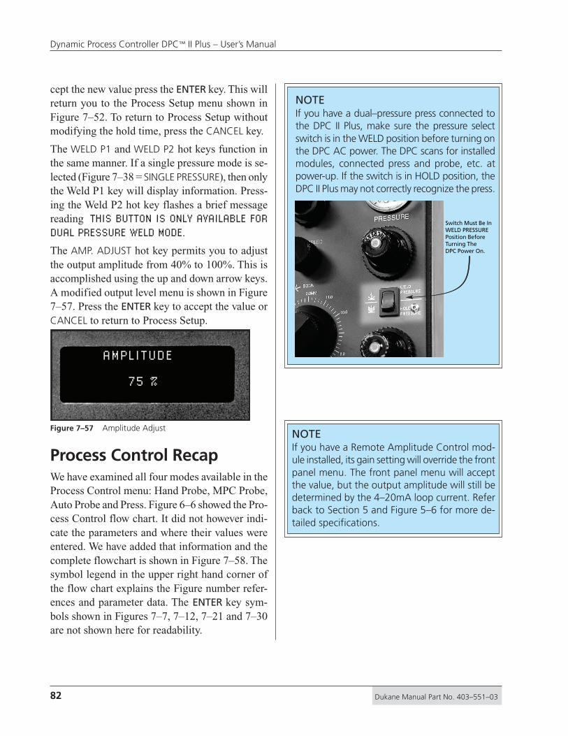
82 Dukane Manual Part No. 403–551–03
Dynamic Process Controller DPC™ II Plus – User’s Manual
cept the new value press the ENTER key. This willreturn you to the Process Setup menu shown inFigure 7–52. To return to Process Setup withoutmodifying the hold time, press the CANCEL key.
The WELD P1 and WELD P2 hot keys function inthe same manner. If a single pressure mode is se-lected (Figure 7–38 = SINGLE PRESSURE), then onlythe Weld P1 key will display information. Press-ing the Weld P2 hot key flashes a brief messagereading THIS BUTTON IS ONLY AVAILABLE FORDUAL PRESSURE WELD MODE.
The AMP. ADJUST hot key permits you to adjustthe output amplitude from 40% to 100%. This isaccomplished using the up and down arrow keys.A modified output level menu is shown in Figure7–57. Press the ENTER key to accept the value orCANCEL to return to Process Setup.
Process Control RecapWe have examined all four modes available in theProcess Control menu: Hand Probe, MPC Probe,Auto Probe and Press. Figure 6–6 showed the Pro-cess Control flow chart. It did not however indi-cate the parameters and where their values wereentered. We have added that information and thecomplete flowchart is shown in Figure 7–58. Thesymbol legend in the upper right hand corner ofthe flow chart explains the Figure number refer-ences and parameter data. The ENTER key sym-bols shown in Figures 7–7, 7–12, 7–21 and 7–30are not shown here for readability.
AMPLITUDE
75 %
Figure 7–57 Amplitude AdjustNOTEIf you have a Remote Amplitude Control mod-ule installed, its gain setting will override the frontpanel menu. The front panel menu will acceptthe value, but the output amplitude will still bedetermined by the 4–20mA loop current. Referback to Section 5 and Figure 5–6 for more de-tailed specifications.
NOTEIf you have a dual–pressure press connected tothe DPC II Plus, make sure the pressure selectswitch is in the WELD position before turning onthe DPC AC power. The DPC scans for installedmodules, connected press and probe, etc. atpower-up. If the switch is in HOLD position, theDPC II Plus may not correctly recognize the press.
Switch Must Be InWELD PRESSUREPosition BeforeTurning TheDPC Power On.

83Dukane Manual Part No. 403–551–03
Section 7 – Process Control Menu
TRIGGER METHOD
PRESSTIMED PROBE
MANUAL
INITIATEMODE
AUTO
MOMENTARY MAINTAINED
TRIGGER TYPE
ENABLE or DISABLE
AUTO STOP
WELDMODE
1 1
2 2
HOLDTIME
PROCESS CONTROLAFTER–BURST
WELDMETHOD
HOLDTIME
PROCESS CONTROL
AFTER–BURST
RTWRTW
RTW
Step 1 Step 2Step 3
TIMEDHANDPROBE
TIMEDMPCPROBE
TIMEDAUTOPROBE
UNTIMEDAUTOPROBE
UNTIMEDMPCPROBE
UNTIMEDHANDPROBE
Step 1 Step 2Step 3
RTW = READY TO WELD
RTW = READY TO WELD
TIMED UNTIMED TIMED UNTIMED TIMED UNTIMED
AUTOPROBE
MPCPROBE
HANDPROBE
AUTO STOP
ENABLE DISABLE
HEAD UP ONAUTO STOP
WELD MODEDUAL
PRESSURESINGLE
PRESSURE
WELD METHOD
TIME ENERGY GND.DETECT
WELD METHOD
TIME ENERGY GND.DETECT
WELD METHOD
TIME ENERGY GND.DETECT
RTWRTW
WELD METHOD
TIME ENERGY
PRESSURE 1TIME ENERGY
PRESSURE 2TIME ENERGY
ENABLE DISABLE
UNTIMED PROBE
PROCESSCONTROL
PROCESSSETUP
Enable/Disable E/D
Enable/Disable E/D
Tde
lay
Tho
ld
Tho
ld
Tw
eld
Tw
eld
Tde
lay
Tbu
rst
Tde
lay
Tbu
rst
Ew
eld
Ew
eld
Ew
eld
Tm
ax
Tm
axT
max
Tm
axT
scru
b
Tw
eld
Ew
eld
Tm
ax
Tw
eld
Ew
eld
Tm
ax
Tw
eld
Ew
eld
Tm
ax
Tm
axT
scru
b
Tm
axT
scru
b
Tw
eld
Tde
lay
HandProbeTriggerSwitch
HandProbe
TriggerSwitch
7–48
7–47
7–46
7–45
7–37
7–36
7–35
7–34
7–13
7–147–14
7–13
7–15
7–22
7–23 7–25
7–26
7–24
7–16
7–5
7–6
7–8
7–9
7–29
7–33
7–52
7–447–42
7–41
7–40
7–39
7–38
7–43
7–52
7–51
7–10
7–11
7–17
7–18
7–18
7–20
7–16
7–15
7–15
7–17
7–18
7–18
7–20
7–16 7–17
7–18
7–18
7–20
7–49
7–50
7–27
7–28
7–16
7–16
SYMBOL LEGEND
Menu and LogicPath appear inthis Figure No.
Menu in differentlogic path butlooks the sameas this Figure No.
Tw
eld Parameter Value
T = Time E = Energy
SINGLEPRESSUREPRESS
DUALPRESSUREPRESS
Figure 7–58 Process Control Menu Flowchart

84 Dukane Manual Part No. 403–551–03
Dynamic Process Controller DPC™ II Plus – User’s Manual
Table 7—I below summarizes the various methodand mode menus and references their Figure num-ber. Table 7–II on the next page lists the data entryscreens and references their Figure number. It alsogives the minimum and maximum values for eachof the parameters. The only variation betweenmodels is for weld energy. The high–frequency(50kHz and 70kHz) models have a lower poweroutput, and the scale factor change enables 0.1Joule resolution at these lower power levels.
Remarks
7–36Momentary or MaintainedTRIGGER TYPE
7–38Single or Dual PressureWELD MODE
7–39Time or EnergyWELD METHOD P1
7–41Time or EnergyWELD METHOD P2
7–35Manual or AutoINITIATE MODE
7–26, 7–48Enable or DisableAFTERBURST
7–25, 7–47AfterburstPROCESS CONTROL
7–23, 7–45Hold TimePROCESS CONTROL
7–22Weld MethodPROCESS CONTROL
7–37, 7–51Weld ModePROCESS CONTROL
7–15WELD METHOD Weld By Time, Energy or Ground Detect
7–13Enable or DisableAUTO STOP
7–8Weld By Time or EnergyWELD METHOD
7–6Probe - Timed or UntimedTRIGGER METHOD
7–34PressTRIGGER METHOD
7–4, 7–297–33, 7–52
Root MenuPROCESS SETUP
6–3, 7–37–4, 7–53
Previous Weld Cycle DataWELD CYCLE DATA
6–2, 7–2Installed ModulesCONFIGURATION
6–1, 7–1DPC II Plus Firmware Version and DateSTARTUP
Description Figure No.Menu Name
Dual Pressure Mode Only
Dual Pressure Mode Only
Press Trigger Method Only
Press Trigger Method Only
Press Trigger Method Only
Press Trigger Method Only
Probe Trigger Method
Press Board or Power OutputModules
Table 7—I Process Control Menu Listing
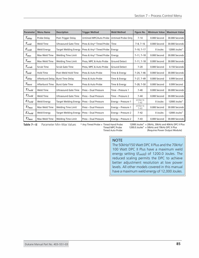
85Dukane Manual Part No. 403–551–03
Section 7 – Process Control Menu
Parameter Description Figure No.Weld Method Minimum Value
Weld Time Ultrasound Gate Time 0.000 Second7–8, 7–16 30.000 SecondsTweld
Weld Energy Target Welding Energy 0 Joules7–10, 7–17Energy
Energy
Ground Detect
Ground Detect
Untimed Probe Only
Time
12000 Joules†Eweld
Max Weld Time Welding Time Limit 0.000 Second7–11, 7–18 30.000 SecondsTmax
Max Weld Time Welding Time Limit 0.000 Second7–11, 7–18 30.000 SecondsTmax
Scrub Time Scrub Gate Time 0.000 Second 0.150 SecondsTscrub
Probe Delay Post–Trigger Delay 0.000 Second7–14 30.000 SecondsTdelay
Time & EnergyHold Time Post–Weld Hold Time 0.000 Second 30.000 SecondsThold
Time & EnergyAfterburst Delay Burst Time Delay 0.000 Second7–27, 7–49
7–20
7–24, 7–46
7–28, 7–50
7–40
7–44
similiar to7–42
similiar to7–43
7–42
7–43
0.999 SecondTdelay
Time & Energy
Trigger Method
Press & Any* Timed Probe
Energy – Pressure 1Weld Energy Target Welding Energy 0 Joules 12000 Joules†E1weld Press – Dual Pressure
Energy – Pressure 2Weld Energy Target Welding Energy 0 Joules 12000 Joules†E2weld Press – Dual Pressure
Press & Any* Timed Probe
Energy – Pressure 1Max Weld Time Welding Time Limit 0.000 Second 30.000 SecondsT1max Press – Dual Pressure
Energy – Pressure 2Max Weld Time Welding Time Limit 0.000 Second 30.000 SecondsT2max Press – Dual Pressure
Press, MPC & Auto Probe
Press, MPC & Auto Probe
Untimed MPC/Auto Probe
Press & Any* Timed Probe
Weld Time Ultrasound Gate Time 0.000 Second 30.000 SecondsT2weld Time – Pressure 2Press – Dual Pressure
Weld Time Ultrasound Gate Time 0.000 Second 30.000 SecondsT1weld Time – Pressure 1Press – Dual Pressure
Press & Auto Probe
Press & Auto Probe
Press & Auto ProbeAfterburst Time Burst Gate Time 0.000 Second 0.999 SecondTburst
Maximum ValueMenu Name
12000 Joules† = 20kHz, 30kHz and 40kHz DPC II Plus1200.0 Joules† = 50kHz and 70kHz DPC II Plus (Requires Power Output Module)
* Any Timed Probe = Timed Hand ProbeTimed MPC ProbeTimed Auto Probe
Table 7—II Parameter Min–Max Values
NOTEThe 50kHz/150 Watt DPC II Plus and the 70kHz/100 Watt DPC II Plus have a maximum weldenergy setting (Eweld) of 1200.0 Joules. Thereduced scaling permits the DPC to achievebetter adjustment resolution at low powerlevels. All other models covered in this manualhave a maximum weld energy of 12,000 Joules.

86 Dukane Manual Part No. 403–551–03
Dynamic Process Controller DPC™ II Plus – User’s Manual
This page intentionally left blank

87Dukane Manual Part No. 403–551–03
Section 7 – Process Control Menu
Process Limits Menu
Dukane Corporation • • Ultrasonics Division
SECTION 8
Process Limits Menu...................................... 89Limit Definition ............................................. 90Suspect and Bad Limits ................................. 90Process Limits ............................................... 90
Single Pressure Mode ...........................................91
Dual Pressure Mode .............................................92
• Limit Definition
• Suspect and Bad Limits
• Process Limits

88 Dukane Manual Part No. 403–551–03
Dynamic Process Controller DPC™ II Plus – User’s Manual
This page intentionally left blank

89Dukane Manual Part No. 403–551–03
Section 8 – Process Limits Menu
Process Limits MenuThe Process Limits Menu allows you to defineupper and lower bounds for suspect parts or forbad parts. The limits are available in both unitsof time and units of energy depending upon thewelding method chosen in Process Control setup.In addition, if a dual–pressure welding methodis selected, total time and/or total energy limitsare also available for suspect or bad parts. Thesame memory location is used for suspect andbad part limits. The difference is that exceedinga bad part limit terminates the weld cycle. Ex-ceeding a suspect limit allows the weld cycle tocontinue until it finishes normally or exceeds aTotal limit. There are 12 different limit settingswhich are broken down as follows:1a. There are two possible BAD PART UPPER TIME
LIMITS (one for each pressure level).1b. There are two possible BAD PART UPPER ENERGY
LIMITS (one for each pressure level).1c. There is one TOTAL BAD PART UPPER TIME LIMIT
and one TOTAL BAD PART UPPER ENERGY LIMIT.This makes a total of six BAD PART UPPER
LIMITS.2. There are six BAD PART LOWER LIMITS.
During a dual–pressure mode welding cycle how-ever, only six of the limits (eight in mixed mode)are applicable. In single pressure mode, this dropsto two usable limits at any one time since thetotals are available only in dual mode. For ex-ample, you can set both upper time and energylimits, but only the upper time limit is recognizedin the weld by time mode.
Table 8—I summarizes the 8 limits recognized in
a dual–pressure, mixed–mode welding cycle.Table 8—II summarizes the 6 limits recognized in
a dual–pressure, uniform–mode welding cycle.Table 8—III lists the 2 limits recognized in a single–
pressure welding cycle.
A Bad Parts Counter is also available in the Utili-ties menu which is covered in the next section.
Cycle State Parameter Limit Type
P1 T(E)U P1 Upper TIME(ENERGY) Limit
P2 Upper ENERGY(TIME) Limit
Total Upper TIME Limit
Total Upper ENERGY Limit
P1 Lower TIME(ENERGY) Limit
P2 Lower ENERGY(TIME) Limit
Total Lower TIME Limit
Total Lower ENERGY Limit
P2 E(T)U
Total TU
Total EU
P1 T(E)L
P2 E(T)L
Total TL
Total EL
Cycle State Parameter Limit Type
P1 T(E)U P1 Upper TIME(ENERGY) Limit
P2 Upper TIME(ENERGY) Limit
Total Upper TIME(ENERGY) Limit
P1 Lower TIME(ENERGY) Limit
P2 Lower TIME(ENERGY) Limit
Total Lower TIME(ENERGY) Limit
P2 T(E)U
Total T(E)U
P1 T(E)L
P2 T(E)L
Total T(E)L
Cycle State Parameter Limit Type
P1 T(E)U P1 Upper TIME(ENERGY) Limit
P1 Lower TIME(ENERGY) LimitP1 T(E)L
Table 8—I Recognized Limits in a Dual–PressureMixed–Mode Welding Cycle
Table 8—II Recognized Limits in a Dual–PressureUniform–Mode Welding Cycle
Table 8—III Recognized Limits in a Single–PressureWelding Cycle
DEFINITIONA mixed mode is a dual–pressure weld cycle inwhich one unit of measurement (e.g. time) isused for Pressure 1 and the other unit of mea-surement (e.g. energy) is used for Pressure 2.A uniform mode is a dual–pressure weld cycle inwhich the same unit of measurement (e.g. time)is used for both Pressure 1 and Pressure 2.

90 Dukane Manual Part No. 403–551–03
Dynamic Process Controller DPC™ II Plus – User’s Manual
Limit DefinitionTo access the Limit settings, start from the Pro-cess Setup menu shown in Figure 8–1.
Select PROCESS LIMITS with the cursor and thenpress ENTER. This displays the LIMIT DEFINITIONmenu as shown in Figure 8–2. These steps are in-dicated at the top of Figure 8–4 which is the flowchart for the Limit Definition. Both the suspectLimits and Bad Limits share the same logicalstructure, so no distinction is made between themin this flow chart.
Suspect & Bad LimitsYou can select either a Suspect or Bad Part Limit.A Suspect Limit allows the weld cycle to continue,but causes an error indication in the display (> or< for upper or lower limit). If a Bad Limit isexceeded, the weld cycle is terminated, and an errorindication is displayed (>> or << for upper or lowerlimit) until the next weld cycle is initiated. A badlimit and suspect limit value share the samememory location. To change a Suspect Limit valueto a Bad Limit value, move the cursor to BAD
PROCESS SETUPPROCESS CONTROLPROCESS LIMITSUTILITIES
LIMITS in the Limit Definition menu and pressENTER. The value is now associated with a BadLimit and will now terminate the weld cycle if themeasured value fall outside the boundary limits.
Process LimitsSelect either Suspect Limits or Bad Limits and pressthe ENTER key. The choice can be easily changedlater. The Process Limits menu is then displayed.This is shown in Figure 8–3 as it would appear fora single–pressure mode weld cycle.
LIMIT DEFINITIONSUSPECT LIMITSBAD LIMITS
PROCESS LIMITSTIMEENERGY
Figure 8–1 Process Setup Main Menu
Figure 8–2 Limit Definition Menu
Figure 8–3 Single–Pressure Process Limits Menu
LIMIT SELECTIONYou normally select the alternate unit of mea-surement for bad and suspect limits. If you arewelding by time (Seconds), all the weld cycleshave the same weld time. There should be nomeasurable deviation from the target time value.There will however, be some variation in thepower drawn by each part. Since the time is con-stant, the power and thus the energy will varyslightly between parts. The limit check thereforeshould be in units of energy (Joules). Too low anenergy draw might result from a mechanical stopinterfering with travel. Too much energy drawnmay be caused by a misaligned part resulting ina large mating surface area.
If you are using dual–pressure mixed mode, agood limits check would set the companion limitfor each pressure plus the total time and en-ergy limits. In a dual–pressure uniform mode,only the alternate units for P1, P2 and TOTALwill be meaningful.
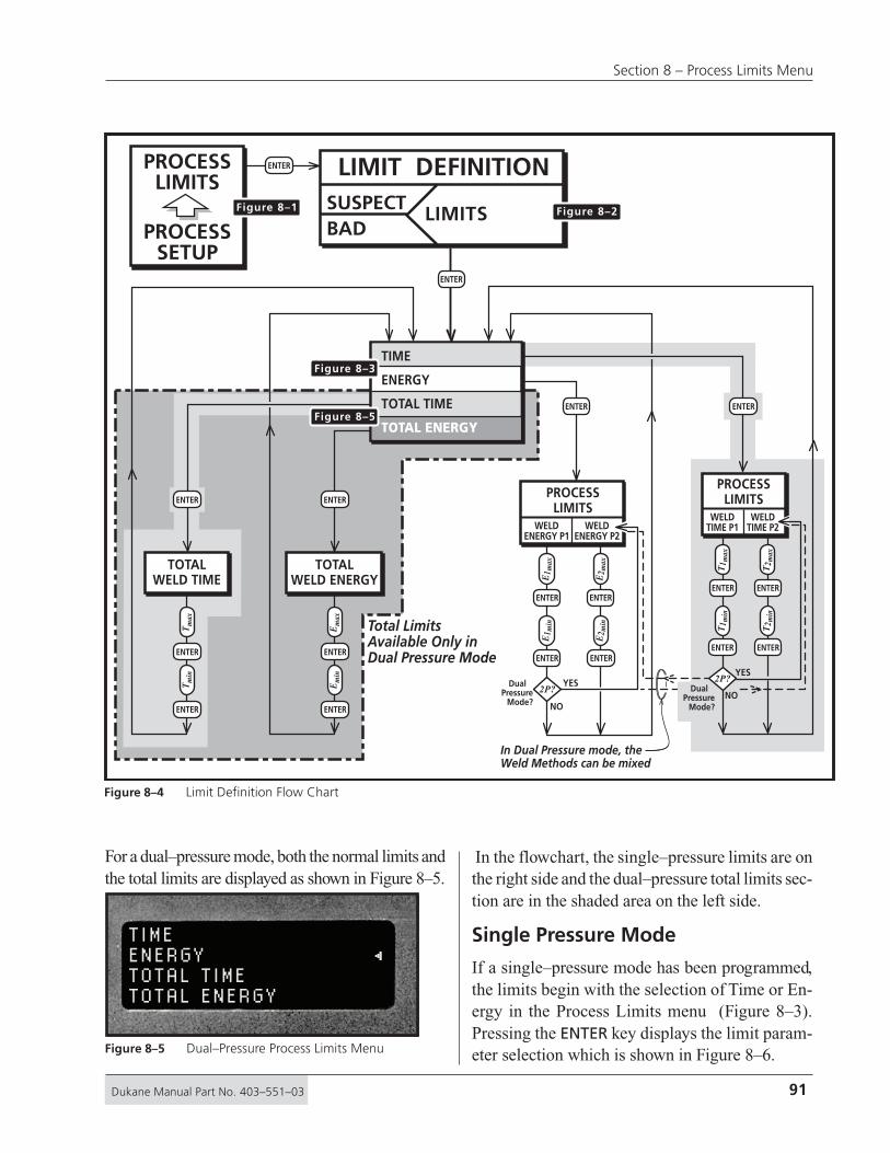
91Dukane Manual Part No. 403–551–03
Section 8 – Process Limits Menu
For a dual–pressure mode, both the normal limits andthe total limits are displayed as shown in Figure 8–5.
In the flowchart, the single–pressure limits are onthe right side and the dual–pressure total limits sec-tion are in the shaded area on the left side.
Single Pressure Mode
If a single–pressure mode has been programmed,the limits begin with the selection of Time or En-ergy in the Process Limits menu (Figure 8–3).Pressing the ENTER key displays the limit param-eter selection which is shown in Figure 8–6.
TIMEENERGYTOTAL TIMETOTAL ENERGY
Total LimitsAvailable Only inDual Pressure Mode
TIME
ENERGY
TOTAL TIME
TOTAL ENERGY
PROCESSLIMITS
WELDTIME P2
WELDTIME P1
PROCESSLIMITS
WELDENERGY P2
WELDENERGY P1
TOTALWELD TIME
TOTALWELD ENERGY
LIMIT DEFINITIONSUSPECTBAD
LIMITS
ENTER
ENTER ENTER
ENTER
ENTER
ENTER ENTER
ENTER
ENTERENTER
ENTER ENTERENTER
ENTERENTER ENTER
ENTER
Dual Pressure
Mode?NO
YES2P?Dual
PressureMode? NO
YES2P?
In Dual Pressure mode, theWeld Methods can be mixed
T1 m
axT
1 min
T2 m
axT
2 min
E1 m
axE
1 min
E2 m
axE
2 min
Tm
axT
min
Em
axE
min
PROCESSLIMITS
PROCESSSETUP
ENTER
Figure 8–1 Figure 8–2
Figure 8–3
Figure 8–5
Figure 8–4 Limit Definition Flow Chart
Figure 8–5 Dual–Pressure Process Limits Menu

92 Dukane Manual Part No. 403–551–03
Dynamic Process Controller DPC™ II Plus – User’s Manual
WELD ENERGY P1 MAXIMUM LIMIT
90 J
PROCESS LIMITSWELD ENERGY P1WELD ENERGY P2
After the minimum and maximum limit values havebeen entered, the display returns to the Process Limitmenu shown in Figure 8–3. Logical comparison en-sures that the minimum value is less than the maxi-mum value before permitting the value to be en-tered. The error screen shown in Figure 8–7 ap-pears briefly and returns to the minimum limit valueentry screen. Reduce the minimum value or pressthe CANCEL key to step back to the maximum limitvalue entry screen and increase its value until thelogical condition is satisfied.
After the minimum and maximum values havebeen entered, the display shows the Process Lim-its Menu (Figure 8–3). Press the CANCEL key toreturn to the Limit Definition Menu (Figure 8–2).Press CANCEL again to return to the Process SetupMenu (Figure 8–1).
Dual Pressure Mode
If a dual–pressure mode has been programmed,the limits selection also includes total values inthe Process Limits menu (Figure 8–5). Firstchoose one of the two top parameters by selectingeither Time or Energy with the cursor. Pressingthe ENTER key displays the limit parameter selec-tion which is shown in Figure 8–8.
LOWER LIMIT MUST BELESS THAN UPPERLIMIT !
WELD ENERGY MAXIMUM LIMIT
270 J
To detect a suspect or bad weld cycle, the mini-mum and maximum values for each pressure limitmust be set. In dual–pressure mode, a logical de-cision function (indicated on the flowchart by thediamond with 2P? inside), diverts the sequenceafter the P1 values have been entered and returnsback to the limit selection menu for the P2 value.You must however move the cursor to the P2 limitbefore pressing ENTER otherwise you will returnback through the P1 section. Pressing the CAN-CEL key will return you to the P1/P2 selectionmenu shown in Figure 8–8. The data entry screensfor dual–pressure mode also identify the P1 or P2pressure phase. The screen for entering the P1Maximum Energy Limit is shown in Figure 8–9.
After the minimum and maximum limit valueshave been entered, the display returns to the Pro-cess Limit menu shown in Figure 8–5. Press theCANCEL key to return to the Limit DefinitionMenu (Figure 8–2). Press CANCEL again to re-turn to the Process Setup Menu (Figure 8–1).
The return sequence flowchart for the CANCELkey is shown in Figure 8–10. Only the energy loopsare labeled to avoid confusion, but the time loopshave the same return sequence.
Figure 8–9 P1 Maximum Energy Data Entry
Figure 8–7 Minimum Value Error Message
Figure 8–6 Single Pressure Max Energy Data Entry Figure 8–8 Dual–Pressure Limits Selection Menu

93Dukane Manual Part No. 403–551–03
Section 8 – Process Limits Menu
TIME
ENERGY
TOTAL TIME
TOTAL ENERGY
PROCESSLIMITS
WELDTIME P2
WELDTIME P1
PROCESSLIMITS
WELDENERGY P2
WELDENERGY P1
TOTALWELD TIME
TOTALWELD ENERGY
LIMIT DEFINITIONSUSPECTBAD
LIMITS
ENTER
ENTER ENTER
ENTER
ENTER
ENTER ENTER
ENTER
ENTER
ENTER
ENTER ENTERENTER
ENTER
ENTER ENTER
ENTER
NO
YES2P?
NO
YES2P?
T1 m
axT
1 min
T2 m
axT
2 min
E1 m
axE
1 min
E2 m
axE
2 min
Tm
axT
min
Em
axE
min
PROCESSLIMITS
PROCESSSETUP
ENTER
Figure 8–1Figure 8–2
Figure 8–3
Figure 8–5
CANCEL
CANCEL
CANCEL
DUALPRESS.
CANCEL
SINGLEPRESS.
CANCEL
CANCEL
CANCEL
Figure 8–10 CANCEL Key Return Path Flow Chart

94 Dukane Manual Part No. 403–551–03
Dynamic Process Controller DPC™ II Plus – User’s Manual
This page intentionally left blank

95Dukane Manual Part No. 403–551–03
Section 8 – Process Limits Menu
Utilities Menu
Dukane Corporation • • Ultrasonics Division
SECTION 9
Setup Utilities ............................................... 97Select Setup .........................................................98
Copy A Setup.......................................................99
Erase Setups .........................................................99
Part Count .................................................. 100Reset Part Count ................................................100
Count Suspect/Bad Parts ....................................100
Preset Part Count ...............................................101
Status Outputs............................................ 101Cycle Press Off Line..................................... 101
• Setup Utilities
• Part Count
• Status Outputs
• Cycle Press Off Line

96 Dukane Manual Part No. 403–551–03
Dynamic Process Controller DPC™ II Plus – User’s Manual
This page intentionally left blank

97Dukane Manual Part No. 403–551–03
Section 9 – Utilities Menu
Utilities MenuThe Utilities Menu is the third option from themain Process Setup menu. It is divided into fourdistinct menu groups:
1. SETUP UTILITIES2. PART COUNT3. STATUS OUTPUTS4. CYCLE PRESS OFF LINE
The basic flowchart for the Utilities Menu wasshown in Figure 6–7. A more detailed flowchartis shown below in Figure 9–1. Unlike the othertwo main menus, the four branches in the Utilitiesmenu are unrelated and independent of each other.They only share a common thread of performingutilitarian functions.
UTILITIESSETUP UTILITIES
ERASECURRENT
SETUP
ERASEALL
SETUPS
STATUSOUTPUTS
ERASESETUPS
LOCAL REMOTE
SETUPTYPEPULSEDMAINTAINED
SETUPUTILITIES
ERASESETUPS
COPYSETUP
SELECTSETUP
PARTCOUNT
PRESETPART
COUNT
COUNTBAD
PARTS
RESETPART
COUNT
PART COUNT
STATUS OUTPUTS
CYCLE PRESS OFF LINE
ENTER
ENTER
ENTER
ENTER
ENTER ENTER
ENTER
ENTERENTER
ENTER ENTER
ENTER
ENTERENTER ENTER
ENTER
ENTER ENTER
ENTER ENTER
UTILITIES
PROCESSSETUP
Count Bad
Parts?
ResetPart Count?
NO
YES
C?
NO
YES
R?
CyclePress Off Line?
NO
YES
C? OK toErase Setups? OK to
EraseSetups?
E?
NO
YES
E?
NO
YESENTERENTER ENTER
ENTER ENTER
From
To
Pre
set #
Setu
p #
Figure 9–1 Utilities Menu Flow Chart
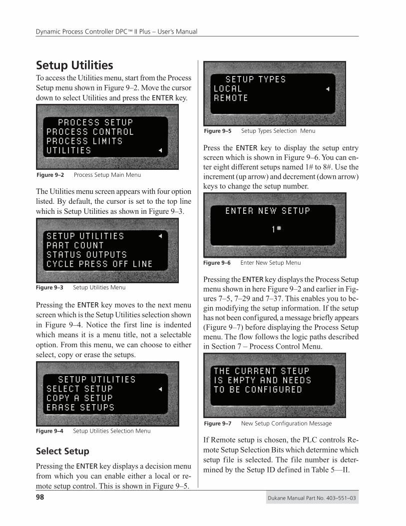
98 Dukane Manual Part No. 403–551–03
Dynamic Process Controller DPC™ II Plus – User’s Manual
Setup UtilitiesTo access the Utilities menu, start from the ProcessSetup menu shown in Figure 9–2. Move the cursordown to select Utilities and press the ENTER key.
PROCESS SETUPPROCESS CONTROLPROCESS LIMITSUTILITIES
The Utilities menu screen appears with four optionlisted. By default, the cursor is set to the top linewhich is Setup Utilities as shown in Figure 9–3.
SETUP UTILITIESPART COUNTSTATUS OUTPUTSCYCLE PRESS OFF LINE
Pressing the ENTER key moves to the next menuscreen which is the Setup Utilities selection shownin Figure 9–4. Notice the first line is indentedwhich means it is a menu title, not a selectableoption. From this menu, we can choose to eitherselect, copy or erase the setups.
SETUP UTILITIESSELECT SETUPCOPY A SETUPERASE SETUPS
Select Setup
Pressing the ENTER key displays a decision menufrom which you can enable either a local or re-mote setup control. This is shown in Figure 9–5.
SETUP TYPESLOCALREMOTE
Press the ENTER key to display the setup entryscreen which is shown in Figure 9–6. You can en-ter eight different setups named 1# to 8#. Use theincrement (up arrow) and decrement (down arrow)keys to change the setup number.
ENTER NEW SETUP
1 #
Pressing the ENTER key displays the Process Setupmenu shown in here Figure 9–2 and earlier in Fig-ures 7–5, 7–29 and 7–37. This enables you to be-gin modifying the setup information. If the setuphas not been configured, a message briefly appears(Figure 9–7) before displaying the Process Setupmenu. The flow follows the logic paths describedin Section 7 – Process Control Menu.
THE CURRENT STEUPIS EMPTY AND NEEDSTO BE CONFIGURED
If Remote setup is chosen, the PLC controls Re-mote Setup Selection Bits which determine whichsetup file is selected. The file number is deter-mined by the Setup ID defined in Table 5—II.
Figure 9–2 Process Setup Main Menu
Figure 9–3 Setup Utilities Menu
Figure 9–4 Setup Utilities Selection Menu
Figure 9–5 Setup Types Selection Menu
Figure 9–6 Enter New Setup Menu
Figure 9–7 New Setup Configuration Message

99Dukane Manual Part No. 403–551–03
Section 9 – Utilities Menu
Copy A Setup
Starting from the Utilities menu in Figure 9–4,move the cursor down to Copy A Setup and pressthe ENTER key. The display first requests thesource file number. This is shown in Figure 9–8.
COPY FROM
1 #
Use the increment and/or decrement key to selecta source file and press the ENTER key. Next thedisplay requests a destination for the file as shownin Figure 9–9. Again, use the increment and/or dec-rement key to select a destination and press theENTER key.
COPY TO
2 #
The display will ask for confirmation before pro-ceeding. This screen is shown in Figure 9–10.
OK TO COPY SETUP? NO Y ES
To proceed, move the cursor down to YES and pressthe ENTER key. The file is copied and the displayreturns to the Setup Utilities selection menu shownin Figure 9–4.
Erase Setups
Again, starting from the Utilities menu in Figure9–4, move the cursor down to Erase Setups andpress the ENTER key. The menu gives us a choiceto erase the current setup or to erase all setups.This menu is shown in Figure 9–11.
ERASE SETUPSERASE CURRENT SETUPERASE ALL SETUPS
The current setup is the one chosen from the Se-lect Setup menu. Press the enter key, and the menuprompts you with a confirmation messages indi-cating the setup to be deleted. This is shown inFigure 9–12.
ERASE SETUP #1 NO YES
To erase the indicated setup, move the cursor downto YES and press ENTER. The display will displaythe message that the setup is being erased (Figure9–13) and return to the Process Setup menu (Fig-ure 9–2). Leaving the cursor at NO and pressingENTER will still return you to the Process Setupmenu (Figure 9–2).
ERASING SETUPIN PROCESS...
Figure 9–8 Source File Location Entry
Figure 9–9 Destination File Location Entry
Figure 9–10 Confirm Copy Files
Figure 9–11 Erase Setups Selection Menu
Figure 9–12 Confirm Erase Selected Setup
Figure 9–13 Erase Setup In Process

100 Dukane Manual Part No. 403–551–03
Dynamic Process Controller DPC™ II Plus – User’s Manual
To erase all the stored setups, move the cursor fromERASE CURRENT SETUP (see Figure 9–11) todown to ERASE ALL SETUPS and press ENTER. Aconfirmation message is displayed. Move the cur-sor down to YES as shown in Figure 9–14. Pressthe ENTER key to delete the setup files.
ERASE ALL SETUPS NO YES
A progress message (see Figure 9–15) appears forabout 8 seconds. When the process is complete,the display returns to the Process Setup menu asshown in Figure 9–2
ERASING ALL SETUPSIN PROCESS... .
Part CountThe parts count option (see Figure 9–3) offers threeoptions. The three choices are to reset the counter,count suspect/bad parts and preset the counter asshown in Figure 9–16.
PART COUNTRESET PART COUNTCOUNT SUS/BAD PARTPRESET PART COUNT
The count replaces the - - - in the upper left of theoperate screen (see Figures 7–3. 7–4, 7–31 and 7–53).
Reset Part Count
This function resets the parts counter back to zero.With the cursor at the reset function, press theENTER key. The confirmation screen shown inFigure 9–17 is displayed next.
RESET PART COUNT NO YES
Use the decrement key to move the cursor downone line to YES and press the ENTER key. Thecounter will be reset and the menu returns to thepart count selection menu shown in Figure 9–16.
Count Suspect/Bad Part
The second option controls the suspect/bad partcounter. The counter can be set to count all parts oronly the good parts. To configure the counter, movethe cursor down to COUNT SUS/BAD PART (seeFigure 9–16) and press ENTER. A confirmationscreen (shown in Figure 9–18) is then displayed.
COUNT SUS/BAD PART NO YES
To count all parts, move the cursor to YES, pressENTER and the menu returns to the part count se-lection screen shown in Figure 9–16. To excludebad/suspect parts, move the cursor to NO and pressENTER. The bad/suspect parts are ignored and onlygood parts are counted. The menu returns to thepart count selection screen shown in Figure 9–16.
Figure 9–14 Confirm Erase All Setups
Figure 9–15 Erasing All Setups In Process
Figure 9–16 Part Count Selection Menu
Figure 9–18 Confirm Counter Enabled
Figure 9–17 Confirm Reset Part Count

101Dukane Manual Part No. 403–551–03
Section 9 – Utilities Menu
Preset Part Count
This option allows you to preset a value (maxi-mum = 60,000) in the counter. Again from the partcount selection menu, move the cursor to the bot-tom line next to PRESET PART COUNT and pressENTER. A data entry screen for presetting the valueis displayed. Use the left and right arrow keys toselect the digit position, and the up and down ar-row keys to increment or decrement the value.
PRESET PART COUNT _0
The underscore indicates the digit position whichis initially under the right–most digit. To preset thecounter, press ENTER and you are returned to thepart count selection menu shown in Figure 9–16.
Status OutputsThe third option in the Utilities Menu (see Figure9–3) is Status Outputs. Moving the cursor downto Status Outputs and pressing the ENTER key dis-plays the Status Output Selection menu.
This menu option permits you to set the four Iso-lated Status Outputs as either maintained or pulsed.The default setting is maintained. If the output isset to pulsed, the output pulse width is 100 msec.The status output selection menu is shown in Fig-ure 9–20. To change the mode, move the cursor toPULSED and press ENTER.
STATUS OUTPUTSMAINTAINEDPULSED
The four outputs controlled by this menu are:1. Isolated Bad Part on Pin 202. Isolated Good Part on Pin 213. Isolated Ready on Pin 224. Isolated In–Dwell on Pin 23
For a complete description of each signal, referback to Table 5—IV.
Cycle Press Off Line
The last option in the Utilities Menu (Figure 9–3)is Cycle Press Off Line. To access this option movethe cursor down to the last line and press ENTER.This subsequent menu is shown in Figure 9–21.
CYCLE PRESS OFF LINE YES NO
This option works only with the palm operateswitches on the press base. When the DPC frontpanel status is set OFF LINE, it cannot be triggeredto cycle the press. During testing or fixture setup,it may be necessary to cycle the press without pro-ducing an ultrasonic output signal. This menu op-tion permits cycling the press with the DPC set toOFF LINE. To enable this menu option, move thecursor key up one line to YES and press the ENTERkey. The press can now be cycled by pressing bothpalm activation switches. without producing an ul-trasonic output signal. An Automation Input signal(pin 8 of J902) will not cycle the press with thismenu option with the DPC set to OFF LINE.
Figure 9–19 Counter Preset Value
Figure 9–20 Status Output Mode Selection
Figure 9–21 Cycle Press Selection Menu

102 Dukane Manual Part No. 403–551–03
Dynamic Process Controller DPC™ II Plus – User’s Manual
This page intentionally left blank

Section 9 – Utilities Menu
Probes & Probe Stacks
Dukane Corporation • • Ultrasonics Division
SECTION 10
The Ultrasonic Probe ................................... 105Theory of Operation ...........................................105
Probe Configuration ...........................................105
Ultrasonic Horn ..................................................106
Booster ..............................................................106
Stack Assembly ........................................... 107Installing Replaceable Tips ..................................107
Mounting Stud to Horn/Booster .........................108
Horn to Booster .................................................109
Booster to Probe ................................................109
Horn to Probe ....................................................109
Torque Unit Conversion Chart ..................... 110Stack Disassembly ....................................... 111Booster Notes............................................ 114Stack Mounting .......................................... 115
• Theory of Operation
• Probe Configuration
• Probe Stack Assembly
• Booster Notes
• Probe Stack Mounting

104 Dukane Manual Part No. 403–551–03
Dynamic Process Controller DPC™ II Plus – User’s Manual
This page intentionally left blank

105Dukane Manual Part No. 403–551–03
Section 10 – Probes and Probe Stracks
The Ultrasonic ProbeTheory of OperationPlastic welding is the most common applicationof ultrasonic assembly. To perform ultrasonic plas-tic welding, the vibrating tip is brought into con-tact with one of the work pieces. Pressure is ap-plied and ultrasonic energy travels through thematerial generating frictional heat at the contactpoint of the two parts. The frictional heat melts amolded ridge of plastic on one of the pieces andthe molten material flows between the two surfaces.When the vibration stops, the material solidifiesforming a permanent bond.
Probe ConfigurationA basic ultrasonic probe package consists of —
1. A probe which houses the transducer to con-vert the electrical energy supplied by the gen-erator into mechanical vibrations.
2. A horn to transfer the mechanical vibrationsfrom the probe to the parts to be welded.
Optional components include special replaceabletips which can be threaded on to the tip of the horn,and a booster to amplify the mechanical vibrationsof the horn. A basic hand–held probe system isshown in Figure 10–1. The hand probe is easilyidentified by its trigger actuator and permanentlyattached cable. Normally a booster is not used witha hand probe as this increases the length and weightand reduces its versatility. The optional threadedtitanium tip can be used when the application callsfor a staking profile or a pointed spot weld. Re-placeable tips are not commonly used in high–vol-ume production environments.
A mounted probe lacks the trigger actuator andhas a HV–BNC connector for attaching the highvoltage coaxial cable. A mounted probe may alsohave a booster to change its output amplitude.
StandardHorn
HandProbe
Tip
CustomHorn
Figure 10–1 Hand Probe, Horn and Tip
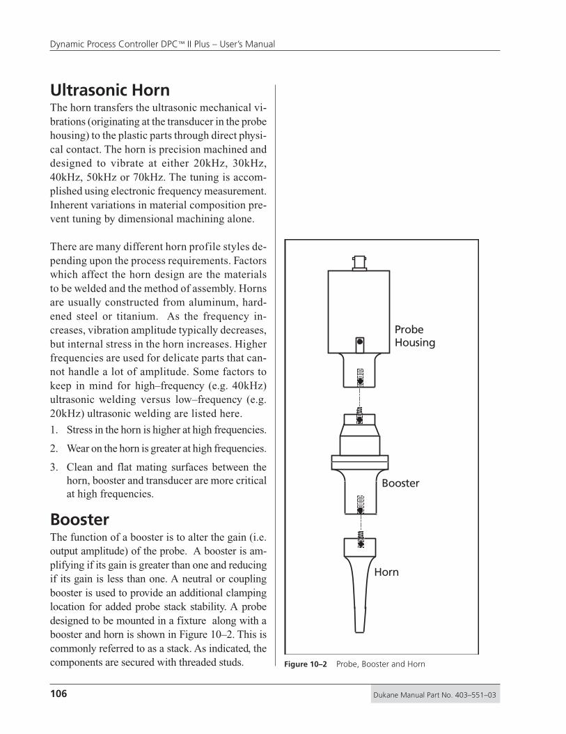
106 Dukane Manual Part No. 403–551–03
Dynamic Process Controller DPC™ II Plus – User’s Manual
Ultrasonic HornThe horn transfers the ultrasonic mechanical vi-brations (originating at the transducer in the probehousing) to the plastic parts through direct physi-cal contact. The horn is precision machined anddesigned to vibrate at either 20kHz, 30kHz,40kHz, 50kHz or 70kHz. The tuning is accom-plished using electronic frequency measurement.Inherent variations in material composition pre-vent tuning by dimensional machining alone.
There are many different horn profile styles de-pending upon the process requirements. Factorswhich affect the horn design are the materialsto be welded and the method of assembly. Hornsare usually constructed from aluminum, hard-ened steel or titanium. As the frequency in-creases, vibration amplitude typically decreases,but internal stress in the horn increases. Higherfrequencies are used for delicate parts that can-not handle a lot of amplitude. Some factors tokeep in mind for high–frequency (e.g. 40kHz)ultrasonic welding versus low–frequency (e.g.20kHz) ultrasonic welding are listed here.
1. Stress in the horn is higher at high frequencies.
2. Wear on the horn is greater at high frequencies.
3. Clean and flat mating surfaces between thehorn, booster and transducer are more criticalat high frequencies.
BoosterThe function of a booster is to alter the gain (i.e.output amplitude) of the probe. A booster is am-plifying if its gain is greater than one and reducingif its gain is less than one. A neutral or couplingbooster is used to provide an additional clampinglocation for added probe stack stability. A probedesigned to be mounted in a fixture along with abooster and horn is shown in Figure 10–2. This iscommonly referred to as a stack. As indicated, thecomponents are secured with threaded studs.
ProbeHousing
Booster
Horn
Figure 10–2 Probe, Booster and Horn
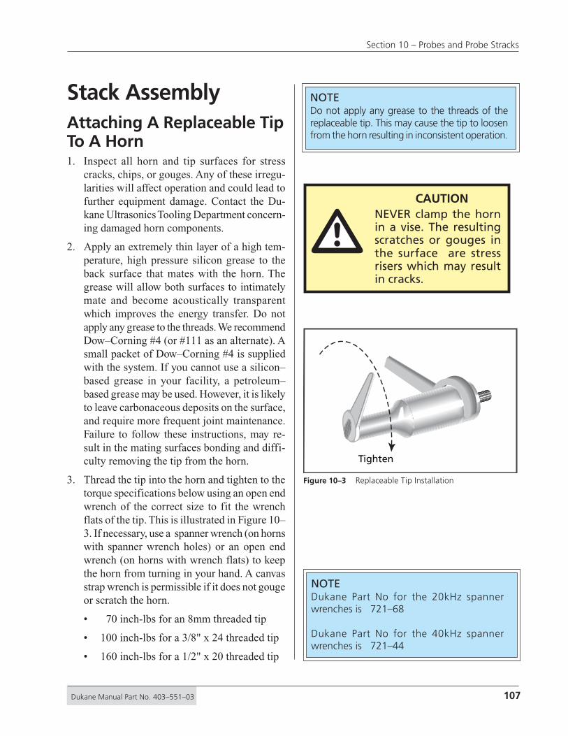
107Dukane Manual Part No. 403–551–03
Section 10 – Probes and Probe Stracks
Stack AssemblyAttaching A Replaceable TipTo A Horn1. Inspect all horn and tip surfaces for stress
cracks, chips, or gouges. Any of these irregu-larities will affect operation and could lead tofurther equipment damage. Contact the Du-kane Ultrasonics Tooling Department concern-ing damaged horn components.
2. Apply an extremely thin layer of a high tem-perature, high pressure silicon grease to theback surface that mates with the horn. Thegrease will allow both surfaces to intimatelymate and become acoustically transparentwhich improves the energy transfer. Do notapply any grease to the threads. We recommendDow–Corning #4 (or #111 as an alternate). Asmall packet of Dow–Corning #4 is suppliedwith the system. If you cannot use a silicon–based grease in your facility, a petroleum–based grease may be used. However, it is likelyto leave carbonaceous deposits on the surface,and require more frequent joint maintenance.Failure to follow these instructions, may re-sult in the mating surfaces bonding and diffi-culty removing the tip from the horn.
3. Thread the tip into the horn and tighten to thetorque specifications below using an open endwrench of the correct size to fit the wrenchflats of the tip. This is illustrated in Figure 10–3. If necessary, use a spanner wrench (on hornswith spanner wrench holes) or an open endwrench (on horns with wrench flats) to keepthe horn from turning in your hand. A canvasstrap wrench is permissible if it does not gougeor scratch the horn.
• 70 inch-lbs for an 8mm threaded tip
• 100 inch-lbs for a 3/8" x 24 threaded tip
• 160 inch-lbs for a 1/2" x 20 threaded tip
Tighten
Figure 10–3 Replaceable Tip Installation
NOTEDukane Part No for the 20kHz spannerwrenches is 721–68
Dukane Part No for the 40kHz spannerwrenches is 721–44
NOTEDo not apply any grease to the threads of thereplaceable tip. This may cause the tip to loosenfrom the horn resulting in inconsistent operation.
CAUTIONNEVER clamp the hornin a vise. The resultingscratches or gouges inthe surface are stressrisers which may resultin cracks.
�

108 Dukane Manual Part No. 403–551–03
Dynamic Process Controller DPC™ II Plus – User’s Manual
Attaching The MountingStud To A Horn Or A Booster1. Inspect the stud for cracks or damaged threads.
Replace the stud if it is cracked or otherwisedamaged.
2. Remove any foreign matter from the threadedstud and the mating hole.
3. Thread the mounting stud into the input* endof the horn or the input* end of the boosterand tighten to the following torque specifica-tions using an allen wrench in the socket headof the mounting stud. Table 10—I lists thetorque specifications in units for both Englishand Metric systems of measurements. Figure10–5 is a handy conversion graph if you requireintermediate values not listed in the tables.
DO NOT hold the booster by the mountingrings when tightening stud. The mounting ringshave a shear pin which could snap under ex-cessive torque. Use a spanner wrench (on hornswith spanner wrench holes) or an open endwrench (on horns with wrench flats) to keepthe horn or booster from turning in your hand.
• 70 inch-lbs for an 8mm threaded stud• 100 inch-lbs for a 3/8" x 24 threaded stud• 160 inch-lbs for a 1/2" x 20 threaded stud
* Always assemble the mounting studs that mate boost-ers, transducers and horns to the input end of thehorn or the input end of the booster first. This isshown in Figures 10–6 and 10–7.NEVER thread a stud into the transducer or the out-put end of the booster first. See Booster Notes inthis section for correctly identifying the output endof a booster.
inch–lbs ft–lbs N–m
70 5.8 7.9
100 8.3 11.3
160 13.3 18.1
Table 10—I Stud Torque Unit Conversions
NOTEDo not apply any grease to the stud threads orthe tapped hole. This may cause the stud toloosen. If the stud wanders within the joint, itcan vibrate, resulting in excessive heat. In somecases, this can melt the tooling material.
NOTETo convert inch-lbs to ft-lbs, divide by 12To convert inch-lbs to Nm, divide by 8.852To convert ft-lbs to Nm, multiply by 1.356To convert Nm to ft-lbs, multiply by 0.7376
Torque specifications have a tolerance of about± 10%.
See Figure 10–4 for a handy conversion graph.

109Dukane Manual Part No. 403–551–03
Section 10 – Probes and Probe Stracks
Attaching The Horn To ABooster, Booster To AProbe, Or Horn To A Probe1. Inspect all surfaces to be joined for stress
cracks, chips, or gouges. Any of these irregu-larities will affect operation and could lead tofurther equipment damage. Contact the Du-kane Ultrasonic Tooling Department concern-ing a damaged booster.
2. Ensure that the mating surfaces of the twocomponents are clean and smooth. These sur-faces must make intimate contact for the me-chanical energy to pass from one componentto the next. Pitting or a buildup of old greaseand dirt on a mating surface will interfere withthe energy transfer and reduce the power de-livered.
3. Make sure that the stud in the horn or boosteris tight. See the preceding mounting stud as-sembly instructions for torque specifications.
4. Remove any foreign matter from the threadedstud and mating hole.
5. Apply an extremely thin layer of a high tem-perature, high pressure silicon grease to thesurface that mates with the horn. The greasewill allow both surfaces to intimately mate andbecome acoustically transparent which im-proves the energy transfer. We recommendDow–Corning #4 (or #111 as an alternate). Asmall packet of Dow–Corning #4 is suppliedwith the system. If you cannot use a silicon–based grease in your facility, a petroleum–based grease may be used. However, it is likelyto leave carbonaceous deposits on the surface,and require more frequent joint maintenance.Grease may be omitted if mylar washers arepreferred on systems that require frequentchanges. Mylar is plastic and will creep undercompression, so mylar is not recommended forsystem that are not changed frequently. Fail-ure to follow these instructions, may result inthe mating surfaces bonding and difficulty re- Figure 10–4 Stack Assembly Procedure
Tighten
NOTEAlways remove a probe stack from the ma-chine in which it is mounted before attachingor removing a horn.
CAUTIONNever leave a horn orbooster assembly handtight. Torque it to theproper specifications be-fore proceeding. If theassembly is installed with-out being properlytorqued down, the assem-bly may vibrate severely,damaging the mating sur-faces and causing thegenerator to overload.
�

110 Dukane Manual Part No. 403–551–03
Dynamic Process Controller DPC™ II Plus – User’s Manual
moving the horn from the booster or thebooster from the probe.
6. Thread the components together and tightento the following torque specifications usingonly the correct size wrenches. Use spannerwrenches on components with spanner wrenchholes or an open end wrench on componentswith wrench flats. See Figure 10–4 for the cor-rect procedure. Refer to Table 10—II for torqueunits conversions. Be careful not overtighten.
• 40kHz Stacks - 130 inch-lbs
• 20kHz Stacks - 200 inch-lbs
inch–lbs ft–lbs N–m
130 10.8 14.7
200 16.7 22.6
5 10 15 20 25 30
5
10
15
20
ft-lbs
N-m0
in-lbs
60
120
180
240
8mm Stud
1/2 x 20 Stud
20kHz Stack
40kHz Stack
3/8 x 24 Stud
200
130
160
70
100
Table 10—II Horn/Booster Torque UnitConversions
Figure 10–5 Torque Value Conversion Graph
NOTEHorn and booster torque specifications arehigher than stud torque specs. Be sure totighten the horn or booster joints to the highertorque limits.Do not tighten the studs to these higher rat-ings as it may induce unnecessary stress in theassembly.
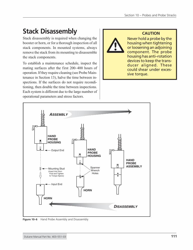
111Dukane Manual Part No. 403–551–03
Section 10 – Probes and Probe Stracks
HORN
HORN
HANDPROBEASSEMBLY
HANDPROBEHOUSING
HANDPROBEHOUSING
ASSEMBLY
DISASSEMBLY
Output End
Input End
SpannerWrenchHoles
Mounting Stud(Insert Into Horn First and Tighten to Torque Specs)
Stack DisassemblyStack disassembly is required when changing thebooster or horn, or for a thorough inspection of allstack components. In mounted systems, alwaysremove the stack from its mounting to disassemblethe stack components.
To establish a maintenance schedule, inspect themating surfaces after the first 200–400 hours ofoperation. If they require cleaning (see Probe Main-tenance in Section 13), halve the time between in-spections. If the surfaces do not require recondi-tioning, then double the time between inspections.Each system is different due to the large number ofoperational parameters and stress factors.
Figure 10–6 Hand Probe Assembly and Disassembly
�CAUTION
Never hold a probe by thehousing when tighteningor loosening an adjoiningcomponent. The probehousing has anti–rotationdevices to keep the trans-ducer aligned. Thesecould shear under exces-sive torque.

112 Dukane Manual Part No. 403–551–03
Dynamic Process Controller DPC™ II Plus – User’s Manual
The assembly and disassembly procedures for ahand probe shown in Figure 10–6. The same pro-cedure for a probe stack with booster is shown inFigure 10–7. It makes no difference whether thehorn is attached to the booster first, or the boosteris attached to the probe first.
PROBEHOUSING
BOOSTER
HORN
UltrasoundCoaxialConnector
Mounting Stud
Input End
SpannerWrench
Hole
SpannerWrench
Hole(Typical)
Output End(Threads Deeper Than Input End)
Booster Input End(Threads Shallower Than Output End)
(Cap Screws Face Toward Input)
BoosterMountingRing(Do not clamp)
BoosterMountingRing(Do not clamp)
Input End
Output End
Mounting Stud(Insert Into Horn First and Tighten to Torque Specs)
(Insert Into Booster Input End First and Tighten to Torque Specs)
PROBESTACKASSEMBLY
ASSEMBLY
DISASSEMBLY
Figure 10–7 Probe Stack with Booster Assembly and Disassembly
�CAUTION
Never hold a probe bythe housing or a boosterby the mounting ringswhen tightening or loos-ening an adjoining com-ponent. The probehousing and boosterrings have anti–rotationdevices to keep thetransducer and boosteraligned and could shearunder excessive torque.

113Dukane Manual Part No. 403–551–03
Section 10 – Probes and Probe Stracks
Separating The Horn From ABooster, Booster From AProbe Or Horn From A ProbeOn all transducers and horns with spanner wrenchholes (see Figures 10–8), use only the correct sizespanner wrench that came with your system to pro-vide sufficient torque to loosen a joint.
On boosters and horns with wrench flats, use onlythe correct size wrench to provide sufficient torqueto loosen a joint when necessary.
Removing The Mounting StudFrom A Horn Or BoosterOnly use an allen wrench of the correct size in thesocket head of stud to remove the stud from thehorn or booster.
Removing Replaceable TipsFrom A HornUse an open end wrench of the correct size to fitthe wrench flats of the detachable tip. Use a span-ner wrench (on horns with spanner wrench holes)or an open wrench (on horns with wrench flats) toprovide an opposite force and keep the horn fromturning in your hand. Refer to Figure 10–9 for thecorrect tip removal procedure.
Loosen
Figure 10–8 Seperating The Horn From The Booster
NOTEDo not hold a booster by the mounting ringswhen removing the stud from the booster. Usea spanner or open–end wrench to provide op-posite force and keep the horn or booster fromturning in your hand when loosening the stud.Use a spanner wrench on horns and boosterswith spanner wrench holes. Use an open endwrench on horns and boosters with wrench flats.
�CAUTION
NEVER clamp a horn orbooster in a vise. The re-sulting scratches orgouges in the surface arestress risers which may re-sult in cracks.
Dukane has a stainless steel tool vise (PartNo.UFTV20) for clamping 20kHz boostersand transducers to facilitate disassembly ofstubborn com-ponents with-out damage. Itaccepts trans-ducer andbooster tool-ing diametersof 1.5 and1.81 inchesand has re-placeable anti-rotation pins.

114 Dukane Manual Part No. 403–551–03
Dynamic Process Controller DPC™ II Plus – User’s Manual
Booster NotesHow To Tell The BoosterInput End From The Output1. The depth of the threaded hole on the output
end is always deeper than the threaded holeon the input end.
2. On an amplifying booster (gain > 1.0), thelarger diameter end is the input end. On a re-ducing booster (gain < 1.0) the larger diam-eter end is the output end. On a neutral actingbooster the diameters are equal.
3. The cap screws on the booster mounting ringsare always inserted from the output end towardthe input end (see Figure 10–7).
How To Tell If The Booster IsAmplifying Or ReducingBoosters have a die-stamped number on their sur-face that indicates their gain or reduction. If the num-ber is greater than 1.0 (e.g. 1.5), it is an amplifyingbooster. If the number is less than 1.0 (e.g. 0.6), it isa reducing or reverse booster. A neutral booster hasno gain and has 1.0 stamped on it. A neutral or cou-pling booster is used to provide another probe stackclamping location for added stability.
Loosen
Figure 10–9 Removing A Replaceable Tip From The Horn
�CAUTION
NEVER install a boosterupside down to changean amplifying system toa reducing system. Theboosters are dimension-ally asymmetric. They aretuned from input to out-put to act like an acousticlens. Reversing them willnot give the expected re-sults and may causedamage to the system.

115Dukane Manual Part No. 403–551–03
Section 10 – Probes and Probe Stracks
Mounting The StackA probe-horn assembly or probe-booster-horn as-sembly (stack) can be mounted into a customer-provided machine to ensure stability and properalignment during operation or for automated op-eration. A stack is secured in a machine by clamp-ing the probe (and booster, when present) at des-ignated locations. Clamping at these designatedlocations provides stability to the stack and at thesame time does not interfere with the transmis-sion of ultrasonic vibrations of the stack compo-nents. The following rules apply when mountinga probe system stack.
1. A probe may be clamped anywhere along itsbody (except the 41S30). If it has a sidemounted BNC, then it may require a thinmounting ring if it is to be clamped near thetop. It may also be clamped below the BNCconnector.
2. Secure a probe-horn stack by clamping theprobe in two places.
3. Secure a probe-booster-horn stack byclamping the probe in one place and thebooster in one place.
4. Never clamp the horn.
NOTENever hold a probe by the housing or boosterby the mounting rings when tightening or loos-ening from an adjoining component (see Figures10–6 and 10–7 to identify these parts). Alwaysuse the proper spanner wrenches when tight-ening or loosening the horn or booster.

116 Dukane Manual Part No. 403–551–03
Dynamic Process Controller DPC™ II Plus – User’s Manual
This page intentionally left blank

117Dukane Manual Part No. 403–551–03
Section 10 – Probes and Probe Stracks
DPC Checkout
Dukane Corporation • • Ultrasonics Division
SECTION 11
Startup and Self–Test .................................. 119System Test ................................................. 120System Operation ....................................... 121Stopping the Weld Cycle............................. 121
Manual Systems .................................................121
Automated System.............................................121
End of Day .........................................................121
• Startup & Self–Test
• System Test
• Probe Operation
• Stopping the Weld Cycle

118 Dukane Manual Part No. 403–551–03
Dynamic Process Controller DPC™ II Plus – User’s Manual
This page intentionally left blank
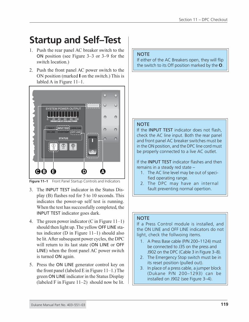
119Dukane Manual Part No. 403–551–03
Section 11 – DPC Checkout
Startup and Self–Test1. Push the rear panel AC breaker switch to the
ON position (see Figure 3–3 or 3–9 for theswitch location.)
2. Push the front panel AC power switch to theON position (marked I on the switch.) This islabled A in Figure 11–1.
3. The INPUT TEST indicator in the Status Dis-play (B) flashes red for 5 to 10 seconds. Thisindicates the power-up self test is running.When the test has successfully completed, theINPUT TEST indicator goes dark.
4. The green power indicator (C in Figure 11–1)should then light up. The yellow OFF LINE sta-tus indicator (D in Figure 11–1) should alsobe lit. After subsequent power cycles, the DPCwill return to its last state (ON LINE or OFFLINE) when the front panel AC power switchis turned ON again.
5. Press the ON LINE generator control key onthe front panel (labeled E in Figure 11–1.) Thegreen ON LINE indicator in the Status Display(labeled F in Figure 11–2) should now be lit.
NOTEIf the INPUT TEST indicator does not flash,check the AC line input. Both the rear paneland front panel AC breaker switches must bein the ON position, and the DPC line cord mustbe properly connected to a live AC outlet.
If the INPUT TEST indicator flashes and thenremains in a steady red state –
1. The AC line level may be out of speci-fied operating range.
2. The DPC may have an internalfault preventing normal opertion.
NOTEIf either of the AC Breakers open, they will flipthe switch to its Off position marked by the O.
STATUS
FAULT
ON LINE
INPUT TEST
OVERTEMP
OVERLOAD
OFF LINE
ONLINE TEST OFF
LINE
0 20 40 60 80 100PERCENTAGE OF AVAILABLE POWERPERCENTAGE OF AVAILABLE POWER
SYSTEM POWER OUTPUT
���� �
NOTEIf a Press Control module is installed, andthe ON LINE and OFF LINE indicators do notlight, check the follwoing items.
1. A Press Base cable (P/N 200–1124) mustbe connected to J35 on the press andJ902 on the DPC (Cable 3 in Figure 3–8).
2. The Emergency Stop switch must be inits reset position (pulled out).
3. In place of a press cable, a jumper block(Dukane P/N 200–1293) can beinstalled on J902 (see Figure 3–4).
Figure 11–1 Front Panel Startup Controls and Indicators
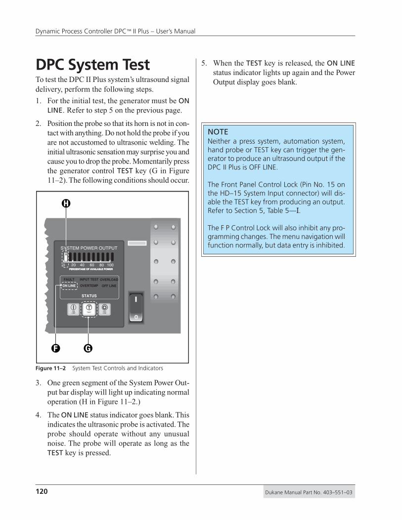
120 Dukane Manual Part No. 403–551–03
Dynamic Process Controller DPC™ II Plus – User’s Manual
DPC System TestTo test the DPC II Plus system’s ultrasound signaldelivery, perform the following steps.
1. For the initial test, the generator must be ONLINE. Refer to step 5 on the previous page.
2. Position the probe so that its horn is not in con-tact with anything. Do not hold the probe if youare not accustomed to ultrasonic welding. Theinitial ultrasonic sensation may surprise you andcause you to drop the probe. Momentarily pressthe generator control TEST key (G in Figure11–2). The following conditions should occur.
3. One green segment of the System Power Out-put bar display will light up indicating normaloperation (H in Figure 11–2.)
4. The ON LINE status indicator goes blank. Thisindicates the ultrasonic probe is activated. Theprobe should operate without any unusualnoise. The probe will operate as long as theTEST key is pressed.
STATUS
FAULT
ON LINE
INPUT TEST
OVERTEMP
OVERLOAD
OFF LINE
ONLINE TEST OFF
LINE
0 20 40 60 80 100PERCENTAGE OF AVAILABLE POWERPERCENTAGE OF AVAILABLE POWER
SYSTEM POWER OUTPUT
� �
�
5. When the TEST key is released, the ON LINEstatus indicator lights up again and the PowerOutput display goes blank.
Figure 11–2 System Test Controls and Indicators
NOTENeither a press system, automation system,hand probe or TEST key can trigger the gen-erator to produce an ultrasound output if theDPC II Plus is OFF LINE.
The Front Panel Control Lock (Pin No. 15 onthe HD–15 System Input connector) will dis-able the TEST key from producing an output.Refer to Section 5, Table 5—I.
The F P Control Lock will also inhibit any pro-gramming changes. The menu navigation willfunction normally, but data entry is inhibited.

121Dukane Manual Part No. 403–551–03
Section 11 – DPC Checkout
System Operation1. If the generator is not online, press the ON
LINE key. This is labeled E in Figure 11–1.The green ON LINE status should light up (Fin Figure 11–2).
2. Program the appropriate weld method and timeor energy to achieve the desired welding results.
3. Apply the probe to the components to be ultra-sonically joined, and press the probe’s activationswitch, or press the palm switches on the pressbase. In automation systems, the customer sup-plies external controls to trigger the generator.
4. The Power Output display will light up to in-dicate the percentage of power being deliveredto the probe while the trigger switch is en-gaged.
5. The Power Output display should never reach100% during normal operation.
6. The Power Output display should go blank in-dicating zero output power, after the probe trig-ger is released.
Stopping the Weld CycleHand Probe System
Release the trigger switch on the hand probeto stop the welding cycle.
Automated SystemThe customer-supplied external controls pro-vide the means to stop the welding cycle foran automated system.
Press SystemPush in the Emergency Stop button on thepress base to stop the welding cycle.
STATUS
FAULT
ON LINE
INPUT TEST
OVERTEMP
OVERLOAD
OFF LINE
ONLINE TEST OFF
LINE
0 20 40 60 80 100PERCENTAGE OF AVAILABLE POWERPERCENTAGE OF AVAILABLE POWER
SYSTEM POWER OUTPUT
End of DayPush the OFF LINE generator control key onthe front panel (I in Figure 11–3).The yellow OFF LINE status indicator (J in Fig-ure 11–3) should be illuminated.
Figure 11–3 Stopping the Weld Cycle
CAUTIONAny unusually loud noisefrom the probe stack in-dicates that it has beenimproperly assembled.Check the probe stack forproper assembly and cor-rect torque readings.

122 Dukane Manual Part No. 403–551–03
Dynamic Process Controller DPC™ II Plus – User’s Manual
This page intentionally left blank

123Dukane Manual Part No. 403–551–03
Section 11 – DPC Checkout
No Ultrasonic Output ..................................... 125Probe .................................................................... 125
Cable .................................................................... 125
Generator ............................................................. 126
Operate Input ....................................................... 126
Generator Faults ............................................ 127OVERLOAD Indicator ............................................. 127
OVERTEMP Indicator ............................................. 127
FAULT Indicator ..................................................... 127
Generator Errors ............................................ 128INPUT TEST Indicator ............................................. 128
TEST Control Key .................................................. 128
Troubleshooting Flowchart ............................. 129Error Messages .............................................. 131
Troubleshooting• No Ultrasonic Output
• Generator Faults
• INPUT TEST Indicatorr
• TEST Control Key
• TroubleshootingFlowchart
• Error Messages
Dukane Corporation • • Ultrasonics Division
SECTION 12

124 Dukane Manual Part No. 403–551–03
Dynamic Process Controller DPC™ II Plus – User’s Manual
This page intentionally left blank
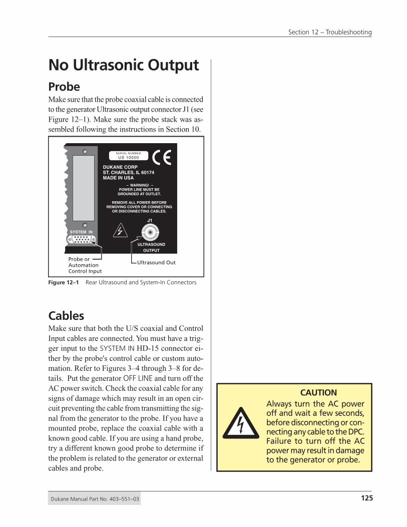
125Dukane Manual Part No. 403–551–03
Section 12 – Troubleshooting
No Ultrasonic OutputProbeMake sure that the probe coaxial cable is connectedto the generator Ultrasonic output connector J1 (seeFigure 12–1). Make sure the probe stack was as-sembled following the instructions in Section 10.
CablesMake sure that both the U/S coaxial and ControlInput cables are connected. You must have a trig-ger input to the SYSTEM IN HD-15 connector ei-ther by the probe's control cable or custom auto-mation. Refer to Figures 3–4 through 3–8 for de-tails. Put the generator OFF LINE and turn off theAC power switch. Check the coaxial cable for anysigns of damage which may result in an open cir-cuit preventing the cable from transmitting the sig-nal from the generator to the probe. If you have amounted probe, replace the coaxial cable with aknown good cable. If you are using a hand probe,try a different known good probe to determine ifthe problem is related to the generator or externalcables and probe.
ULTRASOUND
OUTPUT
J1
SYSTEM IN
– WARNING! –POWER LINE MUST BE
GROUNDED AT OUTLET.
REMOVE ALL POWER BEFOREREMOVING COVER OR CONNECTING
OR DISCONNECTING CABLES.
DUKANE CORPST. CHARLES, IL 60174MADE IN USA
SERIAL NUMBER
US 10000
Ultrasound OutProbe orAutomationControl Input
Figure 12–1 Rear Ultrasound and System-In Connectors
�CAUTION
Always turn the AC poweroff and wait a few seconds,before disconnecting or con-necting any cable to the DPC.Failure to turn off the ACpower may result in damageto the generator or probe.

126 Dukane Manual Part No. 403–551–03
Dynamic Process Controller DPC™ II Plus – User’s Manual
GeneratorThe generator will not produce an output signalwhen triggered if it is OFF LINE. Make sure thatthe green power indicator [A] is lit. The status dis-play should indicate ON LINE which is markedas [B] in Figure 12–2. If the generator is OFFLINE, press the ON LINE control key [C].
Operate InputIf you are using a hand probe, make sure the con-trol cable is connected to the System Input con-nector. The trigger on the hand probe activates theUltrasonic output through the control cable.
If you have supplied custom automation signals,pin 8, or pins 3 & 4 of the Operate Input must beused to trigger the Ultrasonic output. The systemcontrol inputs are user configurable. Refer to Sec-tion 5, Jumper Block SH707 for a detailed descrip-tion of the options. The factory default setting(JU724) is a contact closure to ground. If you areusing the isolated source jumper position (JU 726),then the input requires a minimum of 5V to trig-ger the generator.
STATUS
FAULT
ON LINE
INPUT TEST
OVERTEMP
OVERLOAD
OFF LINE
ONLINE TEST OFF
LINE
0 20 40 60 80 100PERCENTAGE OF AVAILABLE POWERPERCENTAGE OF AVAILABLE POWER
SYSTEM POWER OUTPUT
�� �
Figure 12–2 Generator ON LINE Key and Indicator
NOTEFigure 5–3 shows the male cable end of theSystem Input connector and is repeated here.The cable end connector is a mirror image ofthe female panel connector shown in Figure5–2. Make sure you have correctly wired theconnector if you are using custom automa-tion signals.
1 2 3 4 5
6 10
11 12 13 14 15
127Dukane Manual Part No. 403–551–03
Section 12 – Troubleshooting
Generator FAULTsOVERLOADIf the generator OVERLOAD light comes on, it in-dicates excessive power is being drawn. This couldbe caused by a mismatch between the ultrasonicsignal and the resonant characteristics of the acous-tic stack. Improperly assembled probes may drawexcessive power if their components were notproperly torqued to specifications. Make sure youhave the correct probe and horn. A 40kHz probeand a 20kHz DPC may result in an instantaneousoverload. The same is true for the reverse combi-nation. Excessive power drawn by the load mayresult in damage to the probe and horn.
OVERTEMPIf the OVERTEMP indicator comes on, it indicatesthat one of the generator’s power modules has over-heated. This may occur due to a cooling fan fail-ure or excessive dust inside the cooling channel.The module’s temperature sensor will automati-cally shut down the generator. The generator willautomatically reset and turn off the OVERTEMPindicator when the module temperature drops be-low the 75°C (167°F) trip point.
FAULTIf the generator FAULT light comes on, it indicatesan out–of–tolerance voltage condition. This couldbe related to one of two conditions.
1. AC line voltage out of tolerance. Refer to Table15—I for the AC voltage specifications.
2. Internal DC power supply problems (+5VDC,+12VDC, –12VDC or +24VDC).
If the AC line voltage is within tolerance, thenthe DPC has an internal fault. Contact yourlocal Dukane representative.
NOTEThe OVERLOAD, OVERTEMP and FAULT indica-tors are triggered by independent sensors. It ispossible to get more than one error indicator.The ultrasonic output is disabled on any one ofthe errors.

128 Dukane Manual Part No. 403–551–03
Dynamic Process Controller DPC™ II Plus – User’s Manual
Generator ErrorsINPUT TEST IndicatorSteady Red
During power up, the INPUT TEST indicatorshould flash red for 5–10 seconds. This indi-cates the power-up test is running. When thetest has successfully completed, the INPUTTEST indicator goes out. If the INPUT TESTindicator flashes and then remains in a steadyred state, there are two possible causes.1. The AC line level may be out of the speci-fied operating range. Check the AC power todetermine if it is within the limits specified inSection 15.2. If the AC power is within specifications,the DPC has an internal circuit fault prevent-ing normal operation. Contact your local Du-kane representative.
Does Not FlashIf the INPUT TEST indicator does not flash dur-ing power up, check the AC line input. Boththe rear panel and front panel AC breakerswitches must be in the ON position, and theDPC line cord must be properly connected toa live AC outlet. The generator will not turnon if the line voltage is below the rated mini-mum. The INPUT TEST indicator should lightup even without a probe connected.
TEST Control KeyThe TEST key should cause the first green baron the power display to light even without aprobe (see System Test in Section 11 and Fig-ure 11–2). If the TEST control key will not trig-ger the INPUT TEST light, check that pin 15of the System Input is not grounded. A con-tact closure between this pin and ground (pin2 or 7) will lock out the front panel TEST key.

129Dukane Manual Part No. 403–551–03
Section 12 – Troubleshooting
INPUT TESTindicatorlights up
?
INPUT TESTflashes for5–10 sec
?
1. Both the front and rear AC breaker switches on the DPC must be turned on (Figure 3–9 and 4–2).2. Make sure the AC outlet has power.
YES
NO
YES
NOVerify that the AC voltage is within specifications.
INPUT TESTindicatorgoes out
?
YES
NOVerify that the AC voltage is within specifications.
START
GreenAC powerlight on
?
YES
NO 1. Defective power indicator lamp.2. Internal fault – contact Dukane Service.
FAULTindicator
off?
YES
NOVerify that the AC voltage is within specifications.
A (Continued on next page)
(Plug in AC Powercord into outlet)
Figure 12–3 Troubleshooting Flowchart – Part 1

130 Dukane Manual Part No. 403–551–03
Dynamic Process Controller DPC™ II Plus – User’s Manual
1. Make sure correct probe is connected to generator.2. Check the ultrasonic coaxial cable for shorts.3. Try changing the probe and/or cable.4. Make sure probe stack is properly assembled.
1. If Press Module installed, check J902. 2. Check Emergency Stop is not pushed in.3. Internal fault – contact Dukane Service.
1. If Press Module installed, check J902.2. Internal fault – contact Dukane Service.
(Continued from previous page)
Allow module(s) to cool down. Check cooling fan andcooling channel for excessive dust build up.
Disconnect the probe cables from DPC. The TEST keyshould work even without a probe or SYSTEM I/O cable.Make sure FP Control Lock is not enabled (Table 5—I).
OVERTEMP
indicatoroff?
OVERLOAD
indicatoroff?
YES
NO
YES
NO
ON LINEkey works
?
YES
NO
END
OFF LINEkey works
?
YES
NO
TESTkey works
?
YES
NO
A
Figure 12–4 Troubleshooting Flowchart – Part 2

131Dukane Manual Part No. 403–551–03
Section 12 – Troubleshooting
Error MessagesTRIGGER LOST
This error message is displayed when thetrigger type is set to MAINTAINED, and thetrigger signal is interrupted or lost. Theweld cycle is terminated.
END OF WELD SIGNAL DETECTEDAt the start of the cycle, one or both of theEND OF WELD signals (AUTOMATION END
OF WELD and PRESS END OF WELD) be-comes active. The weld cycle is terminated.
TIMER STOP SIGNAL DETECTEDDuring the weld cycle, the TIMER STOP
signal becomes active. The weld cycleis terminated.
SYSTEM OVERLOAD SIGNAL DETECTEDDuring the weld cycle, the SYSTEM OVER-
LOAD signal becomes active. The weldcycle is terminated.
AUTOMATION FAULT SIGNAL DETECTEDDuring the weld cycle, the AUTOMATION
FAULT signal becomes active. The weldcycle is terminated.
RIGHT SAFETY SWITCH RELEASED TOO SOONIf the Initiate Mode is set to MANUAL, theright safety switch was released too soonat the start of the weld cycle. Both switchesmust be held until the trigger switch is ac-tivated. The weld cycle is terminated.
LEFT SAFETY SWITCH RELEASED TOO SOONIf the Initiate Mode is set to MANUAL, theleft safety switch was released too soon atthe start of the weld cycle. Both switchesmust be held until the trigger switch is ac-tivated. The weld cycle is terminated.
SYSTEM OFF LINEThe SYSTEM OFF LINE signal is active. TheDPC generator must be ON LINE in orderto produce an ultrasonic output signal.
FRONT PANEL LOCKEDKEYPAD ENTRY NOT ALLOWED
If the F P LOCK signal is active, the menunavigation functions normally, but dataentry or program modifications are in-hibited. For more information, refer toSection 5, Table 5—I and the Input Sig-nal Description following the table.

132 Dukane Manual Part No. 403–551–03
Dynamic Process Controller DPC™ II Plus – User’s Manual
This page intentionally left blank

133Dukane Manual Part No. 403–551–03
Section 12 – Troubleshooting
Front Panel ................................................. 135Rear Panel .................................................. 135Chasis ........................................................ 135Stack Surfaces ............................................ 136
Stack Maintenance.............................................136
Stack Inspection .................................................136
Even Contact .....................................................136
Uneven Contact .................................................136
Crowning...........................................................137
Center Depression ..............................................137
Corrosion ...........................................................137
Reconditioning ........................................... 138Overview............................................................138
Machining the Mating Surfaces ..........................138
Manual Resurfacing ...........................................138
Care & Maintenance• Front Panel
• Rear Panel
• Chasis
• Probes
• Reconditioning
Dukane Corporation • • Ultrasonics Division
SECTION 13

134 Dukane Manual Part No. 403–551–03
Dynamic Process Controller DPC™ II Plus – User’s Manual
This page intentionally left blank

135Dukane Manual Part No. 403–551–03
Section 13 – Care & Maintenance
Front PanelCleaningDo not use any solvents or abrasive cleaners onthe front panel. Do not spray cleaner directly ontothe front panel. Apply a small amount of com-puter cleaner to a soft towel first. Clean the panelwith the moistened towel. Do not spray or applythe cleaner directly to the DPC. Do not allow anyliquid to collect around the AC power switch.
DisplayDo not use a sharp object on the display.
Control KeysUse your finger to press the control keys. Do notuse sharp objects on the keys. If your hands aregreasy or contaminated with dirt, use a soft ob-ject like a pencil eraser to push the keys.
Rear PanelConnectorsThe rear panel System Input and Status Outputeach have a pair of 4-40 threaded nuts to securethe connectors. Do not overtighten them
AC Power CordThe AC power cord should be kept in good condi-tion and free from any cuts. The AC plug shouldbe straight with no bent prongs.
Grounding StudThe rear chassis earth ground connection (see Fig-ures 2–5 and 3–3) is a 10–24 x 1/2" threaded stud.Do not overtighten the nut.
ChassisSide Ventilation SlotsKeep the two side ventilation slots free from ob-structions. If excessive dust or dirt collects on theslots, wipe or vacuum them clean. Do not use com-pressed air to clean them as this may force the dirtinside the chassis. The right hand slot (whenviewed from the front) is the air intake and theleft hand side is the exhaust. Allow at least 2 inches(5 cm) on either side for air circulation as shownin Figure 13–1.
2200
2200
STATUS
FAULT
ON LINE
INPUT TEST
OVERTEMP
OVERLOAD
OFF LINE
0 20 40 60 80 100PERCENTAGE OF AVAILABLE POWERPERCENTAGE OF AVAILABLE POWER
SYSTEM POWER OUTPUT
ONLINE
TESTOFFLINE
Dynamic Process ControllerDynamic Process Controller DPC II PlusDPC II Plus
ENTER CANCEL
MODE
ENTERWELD
P1
AMP.
ADJUST
WELD
P2
GEN
INFO.+
–
Intake Vent for Thermostatically Controlled Fan
2"2"
Allow space for ventilation,
2 inches (5 cm) on each side.
Exhaust Air fromFlow–Thru Cooling Tunnel
Figure 13–1 Location of DPC Air Cooling Vents
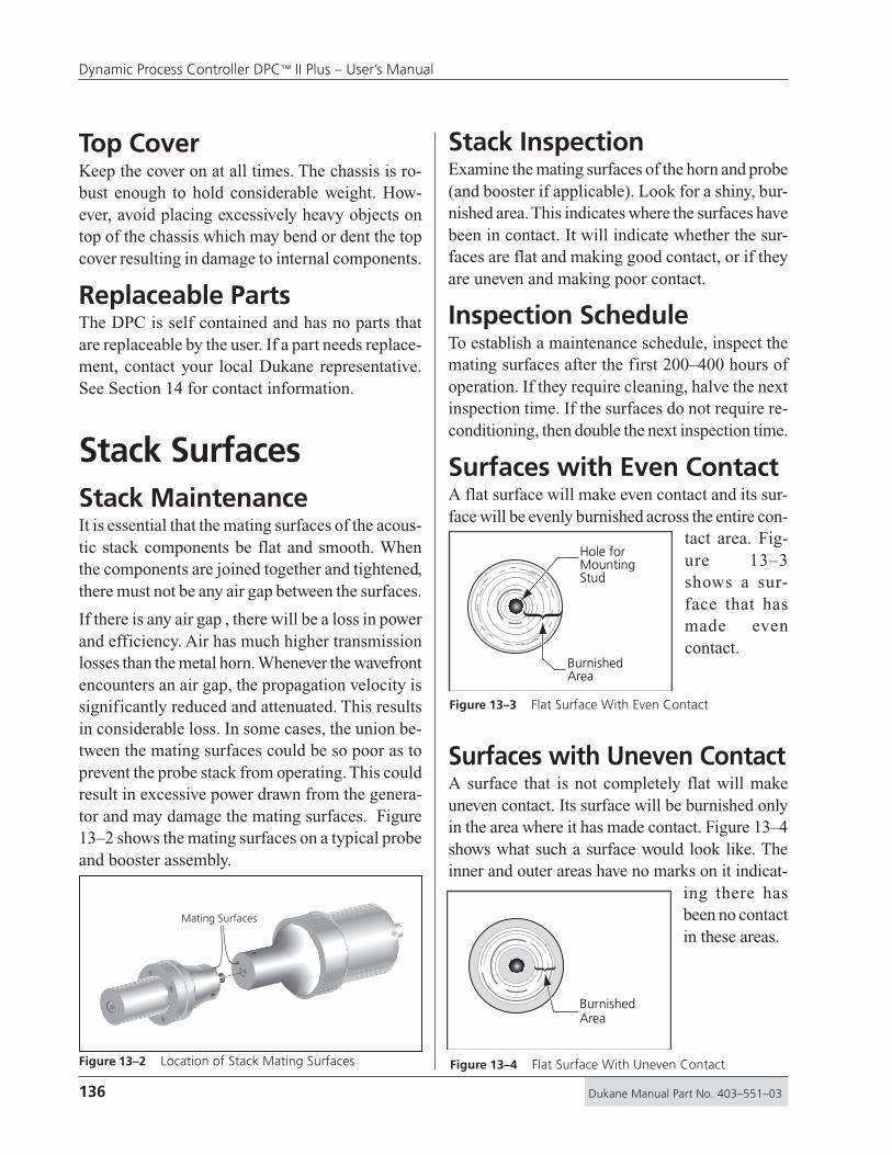
136 Dukane Manual Part No. 403–551–03
Dynamic Process Controller DPC™ II Plus – User’s Manual
Top CoverKeep the cover on at all times. The chassis is ro-bust enough to hold considerable weight. How-ever, avoid placing excessively heavy objects ontop of the chassis which may bend or dent the topcover resulting in damage to internal components.
Replaceable PartsThe DPC is self contained and has no parts thatare replaceable by the user. If a part needs replace-ment, contact your local Dukane representative.See Section 14 for contact information.
Stack SurfacesStack MaintenanceIt is essential that the mating surfaces of the acous-tic stack components be flat and smooth. Whenthe components are joined together and tightened,there must not be any air gap between the surfaces.
If there is any air gap , there will be a loss in powerand efficiency. Air has much higher transmissionlosses than the metal horn. Whenever the wavefrontencounters an air gap, the propagation velocity issignificantly reduced and attenuated. This resultsin considerable loss. In some cases, the union be-tween the mating surfaces could be so poor as toprevent the probe stack from operating. This couldresult in excessive power drawn from the genera-tor and may damage the mating surfaces. Figure13–2 shows the mating surfaces on a typical probeand booster assembly.
Mating Surfaces
Stack InspectionExamine the mating surfaces of the horn and probe(and booster if applicable). Look for a shiny, bur-nished area. This indicates where the surfaces havebeen in contact. It will indicate whether the sur-faces are flat and making good contact, or if theyare uneven and making poor contact.
Inspection ScheduleTo establish a maintenance schedule, inspect themating surfaces after the first 200–400 hours ofoperation. If they require cleaning, halve the nextinspection time. If the surfaces do not require re-conditioning, then double the next inspection time.
Surfaces with Even ContactA flat surface will make even contact and its sur-face will be evenly burnished across the entire con-
tact area. Fig-ure 13–3shows a sur-face that hasmade evencontact.
Surfaces with Uneven ContactA surface that is not completely flat will makeuneven contact. Its surface will be burnished onlyin the area where it has made contact. Figure 13–4shows what such a surface would look like. Theinner and outer areas have no marks on it indicat-
ing there hasbeen no contactin these areas.
BurnishedArea
Hole forMountingStud
}
BurnishedArea
}
Figure 13–2 Location of Stack Mating Surfaces
Figure 13–3 Flat Surface With Even Contact
Figure 13–4 Flat Surface With Uneven Contact

137Dukane Manual Part No. 403–551–03
Section 13 – Care & Maintenance
CrowningA surface which is burnished only in the inner ringarea around the stud, indicates the surface is con-vex or crowned. An example of this is shown infigure 13–5. To get an idea of amount of devia-tion from a flat surface, place a straight edge alongthe stack element. Since its surface is higher atthe center than at the edges, there will be a gap atthe outer edge of the element.
Center DepressionA surface which is burnished only in the outer ringarea around the edge, indicates the surface is con-cave or depressed. An example of this is shown infigure 13–6. To get an idea of amount of deviationfrom a flat surface, place a straight edge along thestack element. Since its surface is higher at the edgethan at the center, there will be a visible gap nearthe center indicating the depth of the depression.
StraightEdge
Crown
Gap
StraightEdge
Gap
CorrosionCorrosion is a factor to consider when determin-ing the overall system performance. Over time,corrosion can build up on the mating surfaces ofthe acoustic stack. This build up interferes withthe efficient transfer of ultrasonic energy to theparts to be welded. It may contribute to a loss inperformance. Evidence of corrosion build up in-cludes discolored mating surfaces or surfaces en-crusted with hard deposits. To extend equipmentlife and maintain performance levels, minimizethe system's exposure to corrosive sources.
Figure 13–5 Crowned Surface
Figure 13–6 Center Depression
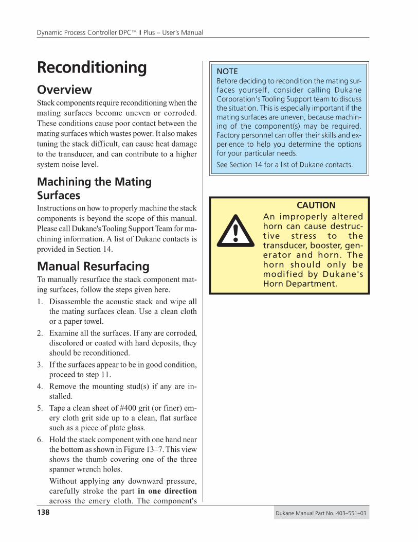
138 Dukane Manual Part No. 403–551–03
Dynamic Process Controller DPC™ II Plus – User’s Manual
ReconditioningOverviewStack components require reconditioning when themating surfaces become uneven or corroded.These conditions cause poor contact between themating surfaces which wastes power. It also makestuning the stack difficult, can cause heat damageto the transducer, and can contribute to a highersystem noise level.
Machining the MatingSurfacesInstructions on how to properly machine the stackcomponents is beyond the scope of this manual.Please call Dukane's Tooling Support Team for ma-chining information. A list of Dukane contacts isprovided in Section 14.
Manual ResurfacingTo manually resurface the stack component mat-ing surfaces, follow the steps given here.
1. Disassemble the acoustic stack and wipe allthe mating surfaces clean. Use a clean clothor a paper towel.
2. Examine all the surfaces. If any are corroded,discolored or coated with hard deposits, theyshould be reconditioned.
3. If the surfaces appear to be in good condition,proceed to step 11.
4. Remove the mounting stud(s) if any are in-stalled.
5. Tape a clean sheet of #400 grit (or finer) em-ery cloth grit side up to a clean, flat surfacesuch as a piece of plate glass.
6. Hold the stack component with one hand nearthe bottom as shown in Figure 13–7. This viewshows the thumb covering one of the threespanner wrench holes.
Without applying any downward pressure,carefully stroke the part in one directionacross the emery cloth. The component's
NOTEBefore deciding to recondition the mating sur-faces yourself, consider calling DukaneCorporation's Tooling Support team to discussthe situation. This is especially important if themating surfaces are uneven, because machin-ing of the component(s) may be required.Factory personnel can offer their skills and ex-perience to help you determine the optionsfor your particular needs.
See Section 14 for a list of Dukane contacts.
CAUTIONAn improperly alteredhorn can cause destruc-tive stress to thetransducer, booster, gen-erator and horn. Thehorn should only bemodified by Dukane'sHorn Department.
�
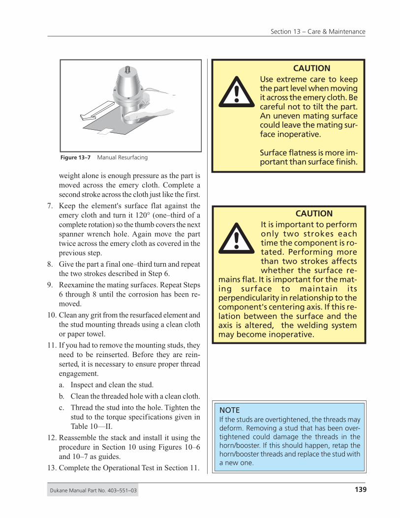
139Dukane Manual Part No. 403–551–03
Section 13 – Care & Maintenance
�CAUTION
Use extreme care to keepthe part level when movingit across the emery cloth. Becareful not to tilt the part.An uneven mating surfacecould leave the mating sur-face inoperative.
Surface flatness is more im-portant than surface finish.
weight alone is enough pressure as the part ismoved across the emery cloth. Complete asecond stroke across the cloth just like the first.
7. Keep the element's surface flat against theemery cloth and turn it 120° (one–third of acomplete rotation) so the thumb covers the nextspanner wrench hole. Again move the parttwice across the emery cloth as covered in theprevious step.
8. Give the part a final one–third turn and repeatthe two strokes described in Step 6.
9. Reexamine the mating surfaces. Repeat Steps6 through 8 until the corrosion has been re-moved.
10. Clean any grit from the resurfaced element andthe stud mounting threads using a clean clothor paper towel.
11. If you had to remove the mounting studs, theyneed to be reinserted. Before they are rein-serted, it is necessary to ensure proper threadengagement.
a. Inspect and clean the stud.
b. Clean the threaded hole with a clean cloth.
c. Thread the stud into the hole. Tighten thestud to the torque specifications given inTable 10—II.
12. Reassemble the stack and install it using theprocedure in Section 10 using Figures 10–6and 10–7 as guides.
13. Complete the Operational Test in Section 11.
CAUTIONIt is important to performonly two strokes eachtime the component is ro-tated. Performing morethan two strokes affectswhether the surface re-
mains flat. It is important for the mat-ing surface to maintain itsperpendicularity in relationship to thecomponent's centering axis. If this re-lation between the surface and theaxis is altered, the welding systemmay become inoperative.
NOTEIf the studs are overtightened, the threads maydeform. Removing a stud that has been over-tightened could damage the threads in thehorn/booster. If this should happen, retap thehorn/booster threads and replace the stud witha new one.
�
Figure 13–7 Manual Resurfacing

140 Dukane Manual Part No. 403–551–03
Dynamic Process Controller DPC™ II Plus – User’s Manual
This page intentionally left blank

141Dukane Manual Part No. 403–551–03
Section 14 – Contacting Dukane
Ultrasonics Division Main Office .................. 143Email Addresses .......................................... 144Telephone Extensions .................................. 144
Contacting Dukane• Corporate Office
• Extensions & eMails
Dukane Corporation • • Ultrasonics Division
SECTION 14

142 Dukane Manual Part No. 403–551–03
Dynamic Process Controller DPC™ II Plus – User’s Manual
This page intentionally left blank

143Dukane Manual Part No. 403–551–03
Section 14 – Contacting Dukane
Department Phone NumbersYou can reach each department by dialing directlyApplication Support (630) 797–4930For applications and/or process technology questions.Engineering (630) 797–4950For engineering of standard and customized systems.Service & Parts (630) 762–4090For equipment servicing or replacement parts.Tooling (630) 797–4930For information on tooling, fixtures and horns.
Department email AddressesApplications: .......................... [email protected]: ........................... [email protected] & Parts: ..................... [email protected]: ................................... [email protected]
Our WebsiteDukane Ultrasonics is on the world wide web at:
http://www.dukcorp.com/usand then go to your area of interest.
Contacting DukaneIdentify EquipmentWhen contacting Dukane about a service–related problem,be prepared to give the following information: • DPC model number, line voltage and serial number • Any fault indicators from the DPC status display • Description of the problem and steps taken to resolve itMany problems can be solved over the telephone, so it isbest to call from a telephone located near the equipment.
Local SupportYour local Dukane representative has received factory training andcan answer all of your questions regarding Dukane equipment.
Ultrasonics DivisionMailing Address: Dukane Ultrasonics
2900 Dukane DriveSt. Charles, IL 60174 USA
Main Phone: (630) 797–4000Main Fax: (630) 797–4949Service & Parts Fax: (630) 584–0796
NOTESee the next page for additionaldepartment phone numbers andemail addresses.

144 Dukane Manual Part No. 403–551–03
Dynamic Process Controller DPC™ II Plus – User’s Manual
Applications: ............................. [email protected]
Engineering: .............................. [email protected]
Food Processing: ....................... [email protected]
International Sales: ................... [email protected]
Marketing: ................................. [email protected]
Sales: .......................................... [email protected]
Support/Service & Parts: ........... [email protected]
Technical Writing: ..................... [email protected]
Tooling: ...................................... [email protected]
Training: .................................... [email protected]
Ultrasonics Division email Addresses
Ultrasonics Division Phone NumbersApplication Support (630) 797–4930
For applications and/or process technology questions.
Engineering (630) 797–4950For engineering of standard and customized systems.
Food Processing (630) 797–4920 or –4938For information about using ultrasonics in food processing.
International (630) 797–4915For questions about international locations, support, etc.
Marketing (630) 797–4906For product literature, and trade show information.
Metal Welding (630) 797–4953For information about any aspect of metal welding.
Sales (630) 797–4918Your local Dukane representative is the mainsource of product and order information, howeveryou may have a need to contact Sales.
Service & Parts (630) 762–4090For equipment servicing or replacement parts.
Technical Writing (630) 797–4907For information and comments about user’smanual content.
Tooling Support (630) 797–4930For information about tooling, horns, and fixturing.
Training Hotline (630) 797–4904We offer a curriculum of educational programs at ourcorporate headquarters in St. Charles, Illinois.Please call the Dukane Ultrasonics Training Hotline for afree Education Catalog or with any questions you may have.
24-hour Emergency ServiceEffective May 10, 2004(630) 797–4987

145Dukane Manual Part No. 403–551–03
Section 14 – Contacting Dukane
Regulatory Compliance ............................... 147Federal Communications Commission ................147
CE Marking (Conformité Europeéne) ..................147
Dimensions ................................................. 148Operating Enviornment............................... 148Power Requirements ................................... 149Interpreting The DPC Model Number .......... 150
Specifications• Regulatory Compliance
• Dimensions
• Power Requirementsand Model Ratings
SECTION 15
Dukane Corporation • • Ultrasonics Division

146 Dukane Manual Part No. 403–551–03
Dynamic Process Controller DPC™ II Plus – User’s Manual
This page intentionally left blank

147Dukane Manual Part No. 403–551–03
Section 15 – Specifications
FCCThe DPC II Plus complies with the following Fed-eral Communications Commission regulations.
• The limits for FCC measurement procedureMP-5, “Methods of Measurement of RadioNoise Emissions from ISM Equipment”, pur-suant to FCC Title 47 Part 18 for UltrasonicEquipment.
CE MarkingThis mark on your equipment certifies that it meetsthe requirements of the EU (European Union) con-cerning interference causing equipment regulations.CE stands for Conformité Europeéne (EuropeanConformity). The DPC II Plus complies with thefollowing CE requirements.
• The EMC Directive 89/336/EEC for heavy in-dustry —EN55011 andEN50082 using
EN61000–4–2EN61000–4–3EN61000–4–4EN61000–4–5EN61000–4–6EN61000–4–8ENV50204
• The Low Voltage Directive 73/23/EEC.
• The Machine Directive 89/392/EEC usingEN60204–1:1993 Safety of Machinery –Electrical Equipment of Machines. Part 1:Specification for General Requirements.
Regulatory Agency Compliance
�CAUTION
DO NOT make anymodifications to theDPC or associatedcables as the changesmay result in violatingone or more regula-tions under which thisequipment is manu-factured.

148 Dukane Manual Part No. 403–551–03
Dynamic Process Controller DPC™ II Plus – User’s Manual
Dimensions
Operating EnvironmentOperate the DPC II Plus within these guidelines:Temperature: 40°F to 100°F (+5°C to +38°C)Pressure: AmbientAir Particulates: Keep the DPC dry.
Minimize exposure to moisture,dust, dirt,smoke and mold.
Humidity: 5% to 95% Non–condensing@ 0°C to +30°C
Vibration: 1.0 G
Storage guidelines:Temperature: -4°F to 158°F (-20°C to +70°C)Humidity: 5% to 95% Non–condensing
@ 0°C to +30°CVibration: 2.5 G
23.78 in604 mm
CoolingAir Inlet
Cooling Fan
Allow 4 in (10 cm)space for cables
Allow 2 in (5 cm)space for ventilation
HeatedExhaust Air
Allow 2 in (5 cm)space for ventilation
Allow 4 in (10 cm)space for cables
17.17 in436 mm
5.12 in130 mm
5.47 in139 mm
���
DUKANE CORPST. CHARLES, IL 60174MADE IN USA
SERIAL NUMBER
US 10000
– WARNING! –POWERLINE MUST BE GROUNDED
AT OUTLET
REMOVE ALL POWER BEFOREREMOVING COVER OR CONNECTING
OR DISCONNECTING CABLES.
ULTRASOUNDOUTPUT
SYSTEM OUT
+
–
Power MonitorJacks
Power SignalOutput Module
PowerSignalOutput
ZeroAdjust
SYSTEM IN
J1
U.S.PATENT 4,277,710
– WARNING–POWER LINE MUST BEGROUNDED AT OUTLET
LINE VOLTAGE200–240Vac 50/60Hz
15A
MODEL NUMBER200-240 VAC, 50-60Hz, 15A
Multi–Probe Slave Module
Multi–Probe Master Module Press Control BoardPower Signal Output
Figure 15–1 Generator 3–View and Dimensions

149Dukane Manual Part No. 403–551–03
Section 15 – Specifications
AC Power RequirementsThe AC power requirements depend on the frequency andpower rating of the DPC II. Table 15—I below, lists boththe nominal AC requirements (maximum current drawnbefore overload) and the service rating of the AC outleteach model of the DPC II Plus is designed for.
2050
2120
2170
2220
3150
4035
4070
4100
5015
701070 kHz
50 kHz
40 kHz
30 kHz
20 kHz
500
1200
1700
2200
1500
350
700
1000
150
100
95–130V 50/60 Hz @ 8 Amps
95–130V 50/60 Hz @ 15 Amps
95–130V 50/60 Hz @ 6 Amps
95–130V 50/60 Hz @ 12 Amps
95–130V 50/60 Hz @ 15 Amps
95–130V 50/60 Hz @ 6 Amps
95–130V 50/60 Hz @ 6 Amps
190–260V 50/60 Hz @ 4 Amps
190–260V 50/60 Hz @ 4 Amps
190–260V 50/60 Hz @ 8 Amps
190–260V 50/60 Hz @ 4 Amps
190–260V 50/60 Hz @ 8 Amps
140015 kHz 4000 190–260V 50/60 Hz @ 30 Amps
190–260V 50/60 Hz @ 8 Amps
190–260V 50/60 Hz @ 12 Amps
190–260V 50/60 Hz @ 12 Amps
190–260V 50/60 Hz @ 4 Amps
190–260V 50/60 Hz @ 15 Amps
2300 3000 190–260V 50/60 Hz @ 25 Amps
30 Amps
30 Amps
15 Amps
15 Amps
15 Amps
15 Amps
15 Amps
15 Amps
15 Amps
15 Amps
15 Amps
15 Amps
15 Amps
15 Amps
15 Amps
15 Amps
15 Amps
15 Amps
15 Amps
FrequencyDPC II PlusModel No.
Peak PowerRating (Watts)
AC OutletCurrent RatingNominal AC Power Requirements
Table 15—I DPC II Plus Generator Model and Power Supply Requirements

150 Dukane Manual Part No. 403–551–03
Dynamic Process Controller DPC™ II Plus – User’s Manual
Interpreting the DPC II Plus Model Number
2200-HN4-PE-L2 Generator Controller Level
FREQUENCY 1 = 15 kHz 2 = 20 kHz 3 = 30 kHz 4 = 40 kHz 5 = 50 kHz 7 = 70 kHz
POWER RATING
015 = 150 W 035 = 350 W 050 = 500 W 070 = 700 W 100 = 1000 W 120 = 1200 W 170 = 1700 W 220 = 2200 W 300 = 3000 W 400 = 4000 W
P = Press Control Board
T = Time OnlyE = Time & Energy
L2 = level 2
010 = 1 0 0 W
N = Non-Power Factor
F = Power Factor Corrected
TRANSDUCERS2 = 2 Ceramics (350W & 700W @ 40kHz All 50kHz and 70kHz)
6 = 6 Ceramics (Custom)
4 = 4 Ceramics (All 20kHz & 30kHz units and the 1000W 40kHz)
INPUT POWER MODULEL = Low Power Module
(All models except those listed below)
X = Extra–High Power Module(4000W @ 15kHz 3000W @ 20kHz)
H = High Power Module(1700W & 2200W @ 20kHz
1500W @ 30kHz 1000W @ 40kHz)
Figure 15–2 Interpeting the DPC II Plus Model Number
NOTEFigure 15-2 is designed to help you determinewhich options your DPC has. It is not meantto suggest that all combinations of these op-tions are possible.

151Dukane Manual Part No. 403–551–03
Section 15 – Specifications
Domestic warranty...................................... 153International Warranty ................................ 154
Warranty• Domestic Warranty
• International Warranty
SECTION 16
Dukane Corporation • • Ultrasonics Division

152 Dukane Manual Part No. 403–551–03
Dynamic Process Controller DPC™ II Plus – User’s Manual
This page intentionally left blank

153Dukane Manual Part No. 403–551–03
Section 16 – Warranty
Subject to the terms, limitations and exclusions set forth below, Dukane Corporation IAS Division (Dukane) warrants to the original Purchaser,
unless otherwise expressly agreed to in writing by Dukane, that all equipment and tooling designed and built by Dukane will be free from
defects in material or workmanship. Normal wear items are not covered by this warranty. Warranty duration shall be defined as documented
herein and in conjunction with any exceptions or exclusions in the accompanying Dukane quotation to the Purchaser.
All Dukane warranties commence on the date of the original shipment of the equipment or tooling, and duration is based upon a singleshift per day, five day per week operation. The warranty period on rentals of new equipment that are converted to a purchase are deemedto have commenced on the initial date of rental.
These warranties are limited to equipment and tooling operated and maintained per Dukane’s written instructions, and used undernormal operating conditions. These warranties do not include normal wear or normal wear items, and do not cover damage attributableto misuse, improper installation, faulty repair, unauthorized alteration or modification, neglect, or accident. Misuse includes operation ofequipment with tooling that is not qualified for the equipment or properly installed on the equipment.
The warranty on all Dukane equipment and tooling purchased and installed in North America is a parts and labor warranty only. Equipmentinstalled outside of North America, regardless of where it was purchased, is covered by Dukane’s International Warranty Policy. In allcases, when on-site service is required, Travel & Living (T&L) expenses will be billed at cost. Warranty service labor (including traveltime) at the customer’s site is provided on a Monday through Friday (excluding holidays), 7 a.m. to 7 p.m. basis. Any warranty servicerequested outside of these hours is available on a charge basis equal to 150% of Dukane’s prevailing rate for technical service work.
Any equipment or tooling that proves to be defective in material or workmanship during the stated warranty period will be repaired orreplaced at the sole discretion of Dukane Corporation when Dukane is promptly notified in writing. During the warranty period, defectiveequipment, components, or tooling that are returned properly packed with all transportation charges prepaid will be repaired or replacedand returned to the end-user without charge. Shipments of warranty parts will be via standard, non-expedited delivery service. Expeditedshipment requests are subject to freight charges to the Purchaser.
Computers, PLCs, CRTs, LCDs, touch screens, and keyboards separate and/or incorporated as an integral part of a system will carry aone (1) year warranty from the date of shipment when used under normal operating conditions, and not subjected to misuse, abuse, orneglect. For all other equipment, components, or parts included in equipment or systems from Dukane, but not manufactured by Dukaneor its affiliates, this warranty shall be limited in time and extent to the warranty given to Dukane by the OEM.
EQUIPMENT WARRANTY EXCLUSIONS OR EXCEPTIONS:When specified in our quotation, a limited warranty may apply to certain components of the equipment, and/or for certain types of
applications of the equipment, including those noted below.
❑ This warranty is void if the ultrasonic welder and/or tooling [i.e., horn(s) and fixture(s)] are used for applications requiring metal-to-metal contact, when the ultrasonic exposure period (weld cycle) exceeds 250 milliseconds.
❑ Ultrasonic Equipment and tooling used in continuous duty cycle modes such as, but not limited to, continuous cut and seal, andfood processing are warranted for 2000 hours or 12 months from shipment, whichever occurs first.
❑ Any ultrasonic horn or tool quoted and sold as “Experimental” is not warranted.
❑ This warranty does not cover failures of equipment and components attributable to improper cooling or overheating of thetransducer.
❑ Ultrasonic Horn Analyzers have a 12-month warranty.
❑ Ultrasonic Transducers have a one-time replacement warranty.
❑ Normal wear items and consumables excluded from any warranty coverage include, but are not limited to, filters, fuses, light bulbs,lubricants, gaskets and seals, cast urethane fixture components, laser flashlamps, laser beam delivery optics, and lasing gases.
The forgoing warranty is the sole and exclusive warranty and is made in lieu of all other warranties, express, impliedor statutory, including without limitation any warranties of merchantability, fitness for a particular purpose, description,quality, productiveness or any other warranty. The remedy set forth in this warranty policy is the sole and exclusiveremedy of Purchaser and in no event shall Dukane be liable for any compensatory, consequential, special, punitiveor contingent damages or for damages arising from any delay in performance by Dukane under this warranty.
DUKANE CORPORATION NORTH AMERICAN WARRANTY POLICY
Equipment Type Equipment Warranty Duration Other Comments
Custom Systems 12 months on all Dukane designed and built content Dukane standard product included in custom systems that is not part of our standard product. are covered by the applicable product warranty.
Hot Plate Welder 24 months none
Laser Welder For all laser sources, Original equipment All internal laser optics and external beam delivery manufacturer (OEM) warranty is applicable. optics are warranted for only 30 days.
Spin Welder 24 months none
Thermal Press 24 months none
Ultrasonic Welder 36 months See WARRANTY EXCLUSIONS OR EXCEPTIONS below.
Vibration Welder 24 months none
All Production 12 months, one-time replacement. (6-month, noneTooling one-time replacement for carbide tipped horns)
Prototype Tooling • All tooling made from Renshape 460 (Renwood) Prototype Renshape 460 (Renwood) tools employ are only warranted for 200 part-cycles. reusable content, and therefore remain the property
• All other prototype tooling is warranted as of Dukane. described in each specific proposal.

154 Dukane Manual Part No. 403–551–03
Dynamic Process Controller DPC™ II Plus – User’s Manual
Subject to the terms, limitations and exclusions set forth below, Dukane Corporation IAS Division (Dukane) warrants to the original Purchaser,
unless otherwise expressly agreed to in writing by Dukane, that all equipment and tooling designed and built by Dukane will be free from
defects in material or workmanship. Normal wear items are not covered by this warranty. Warranty duration shall be defined as documented
herein and in conjunction with any exceptions or exclusions in the accompanying Dukane quotation to the Purchaser.
All Dukane warranties commence on the date of the original shipment of the equipment or tooling, and duration is based upon a singleshift per day, five day per week operation. The warranty period on rentals of new equipment that are converted to a purchase are deemedto have commenced on the initial date of rental.
These warranties are limited to equipment and tooling operated and maintained per Dukane’s written instructions, and used undernormal operating conditions. These warranties do not include normal wear or normal wear items, and do not cover damage attributableto misuse, improper installation, faulty repair, unauthorized alteration or modification, neglect, or accident. Misuse includes operation ofequipment with tooling that is not qualified for the equipment or properly installed on the equipment.
The warranty on all Dukane equipment and tooling purchased and installed in North America is a parts and labor warranty only. Equipmentinstalled outside of North America, regardless of where it was purchased, is covered by Dukane’s International Warranty Policy. In allcases, when on-site service is required, Travel & Living (T&L) expenses will be billed at cost. Warranty service labor (including traveltime) at the customer’s site is provided on a Monday through Friday (excluding holidays), 7 a.m. to 7 p.m. basis. Any warranty servicerequested outside of these hours is available on a charge basis equal to 150% of Dukane’s prevailing rate for technical service work.
Any equipment or tooling that proves to be defective in material or workmanship during the stated warranty period will be repaired orreplaced at the sole discretion of Dukane Corporation when Dukane is promptly notified in writing. During the warranty period, defectiveequipment, components, or tooling that are returned properly packed with all transportation charges prepaid will be repaired or replacedand returned to the end-user without charge. Shipments of warranty parts will be via standard, non-expedited delivery service. Expeditedshipment requests are subject to freight charges to the Purchaser.
Computers, PLCs, CRTs, LCDs, touch screens, and keyboards separate and/or incorporated as an integral part of a system will carry aone (1) year warranty from the date of shipment when used under normal operating conditions, and not subjected to misuse, abuse, orneglect. For all other equipment, components, or parts included in equipment or systems from Dukane, but not manufactured by Dukane
or its affiliates, this warranty shall be limited in time and extent to the warranty given to Dukane by the OEM.
EQUIPMENT WARRANTY EXCLUSIONS OR EXCEPTIONS:When specified in our quotation, a limited warranty may apply to certain components of the equipment, and/or for certain types ofapplications of the equipment, including those noted below.
❑ This warranty is void if the ultrasonic welder and/or tooling [i.e., horn(s) and fixture(s)] are used for applications requiring metal-to-metal contact, when the ultrasonic exposure period (weld cycle) exceeds 250 milliseconds.
❑ Ultrasonic Equipment and tooling used in continuous duty cycle modes such as, but not limited to, continuous cut and seal, andfood processing are warranted for 2000 hours or 12 months from shipment, whichever occurs first.
❑ Any ultrasonic horn or tool quoted and sold as “Experimental” is not warranted.
❑ This warranty does not cover failures of equipment and components attributable to improper cooling or overheating of thetransducer.
❑ Ultrasonic Horn Analyzers have a 12-month warranty.
❑ Ultrasonic Transducers have a one-time replacement warranty.
❑ Normal wear items and consumables excluded from any warranty coverage include, but are not limited to, filters, fuses, light bulbs,
lubricants, gaskets and seals, cast urethane fixture components, laser flashlamps, laser beam delivery optics, and lasing gases.
The forgoing warranty is the sole and exclusive warranty and is made in lieu of all other warranties, express, impliedor statutory, including without limitation any warranties of merchantability, fitness for a particular purpose, description,quality, productiveness or any other warranty. The remedy set forth in this warranty policy is the sole and exclusiveremedy of Purchaser and in no event shall Dukane be liable for any compensatory, consequential, special, punitiveor contingent damages or for damages arising from any delay in performance by Dukane under this warranty.
Equipment Type Equipment Warranty Duration Other Comments
Custom Systems 12 months on all Dukane designed and built content Dukane standard product included in custom systems that is not part of our standard product. are covered by the applicable product warranty.
Hot Plate Welder 12 months none
Laser Welder For all laser sources, Original equipment All internal laser optics and external beam delivery manufacturer (OEM) warranty is applicable. optics are warranted for only 30 days.
Spin Welder 12 months none
Thermal Press 12 months none
Ultrasonic Welder 12 months See WARRANTY EXCLUSIONS OR EXCEPTIONS below.
Vibration Welder 12 months none
All Production 12 months, one-time replacement. (6-month, noneTooling one-time replacement for carbide tipped horns)
Prototype Tooling • All tooling made from Renshape 460 (Renwood) Prototype Renshape 460 (Renwood) tools employ are only warranted for 200 part-cycles. reusable content, and therefore remain the property
• All other prototype tooling is warranted as of Dukane. described in each specific proposal.
DUKANE CORPORATION INTERNATIONAL WARRANTY POLICY

155Dukane Manual Part No. 403–551–03
Section 16 – Warranty
APPENDIX A
Dukane Corporation • • Ultrasonics Division
List of FiguresFigure 2–1 120Volt, Grounded, 3-Prong Receptacle ......................................... 12Figure 2–2 220Volt, Grounded, 3-Prong Receptacle ......................................... 12Figure 2–3 International 220/240V Grounding................................................. 13Figure 2–4 DPC Grounding Arrangement ........................................................ 13Figure 2–5 Press Grounding Arrangement ....................................................... 13
Figure 3–1 Installing a Benchtop DPC .............................................................. 17Figure 3–2 Rack-mounted DPC Using Bracket Kit ............................................. 18Figure 3–3 DPC II Plus Rear Panel & Optional Modules ..................................... 19Figure 3–4 DPC II Plus Hand Probe Cabling Connections.................................. 21Figure 3–5 DPC II Plus Automated Probe Cabling Connections ........................ 21Figure 3–6 DPC II Plus Multiple Probe Cabling Connections ............................. 22Figure 3–7 DPC II Plus Automated Thruster Cabling Connections .................... 23Figure 3–8 DPC II Plus Dukane Press Cabling Connections ............................... 24Figure 3–9 Emergency Stop Switch Interface ................................................... 25Figure 3–10 Rear Panel AC Breaker Switch ........................................................ 25
Figure 4–1 DPC II Plus Control Panel Layout ..................................................... 29Figure 4–2 Front Panel AC Power Section ........................................................ 30Figure 4–3 Generator Control Keys .................................................................. 30Figure 4–4 System Status Display ..................................................................... 31Figure 4–5 Power Output Display Normal Operation ........................................ 32Figure 4–6 Power Output Display Warning Indicators ...................................... 32Figure 4–7 Menu Keys ..................................................................................... 33Figure 4–8 GEN. INFO Menu Display ................................................................ 33Figure 4–9 Menu Display – Typical Selection Menu .......................................... 35Figure 4–10 Menu Display – Typical Confirmation Screen................................... 35Figure 4–11 Menu Display – Typical Data Entry Screen ....................................... 35
Figure 5–1 DPC II Plus Rear Panel Connectors .................................................. 39Figure 5–2 HD–15 System Input Connector ..................................................... 40Figure 5–3 Cable End of System Input Connector ............................................ 40Figure 5–4 DB–25 System Output Connector ................................................... 42Figure 5–5 Remote Amplitude Control Module ................................................ 46Figure 5–6 Current Loop Transfer Function Graph............................................ 46Figure 5–7 Power Signal Output Module ......................................................... 47Figure 5–8 Press Control Module ..................................................................... 48Figure 5–9 Press Connector Pin Identification .................................................. 48Figure 5–10 Press Board SH901 Cycle Activation Jumper ................................... 50Figure 5–11 Master and Slave Multi–Probe Controller Modules ......................... 51Figure 5–12 Card Slot, Connector & Jumper Block Locations ............................. 53Figure 5–13 Jumper Block Details ...................................................................... 54

156 Dukane Manual Part No. 403–551–03
Dynamic Process Controller DPC™ II Plus – User’s Manual
Figure 6–1 DPC II Plus Startup Menu ............................................................... 57Figure 6–2 DPC II Plus Configuration Menu ..................................................... 57Figure 6–3 DPC II Plus Weld Cycle Display ........................................................ 57Figure 6–4 DPC II Plus Process Setup Menu...................................................... 57Figure 6–5 Process Setup Main Menu Structure ............................................... 58Figure 6–6 Process Control Menu Flowchart .................................................... 59Figure 6–7 Limit Definition Menu Flowchart .................................................... 60Figure 6–8 Utilities Menu Flowchart ................................................................. 61
Figure 7–1 DPC II Plus Startup Menu ............................................................... 65Figure 7–2 DPC II Plus Configuration Menu ..................................................... 65Figure 7–3 DPC II Plus Time Weld Cycle Display ............................................... 65Figure 7–4 DPC II Plus Energy Weld Cycle Display ............................................ 65Figure 7–5 Process Setup Menu ....................................................................... 66Figure 7–6 Process Control Trigger Method Menu ........................................... 66Figure 7–7 Hand Probe Flow Chart .................................................................. 66Figure 7–8 Hand Probe Weld Method Menu .................................................... 67Figure 7–9 Hand Probe Weld Time Menu ........................................................ 67Figure 7–10 Hand Probe Weld Energy Menu...................................................... 67Figure 7–11 Hand Probe Maximum Weld Time Menu ........................................ 67Figure 7–12 Multi–Probe Controller Flowchart ................................................... 68Figure 7–13 Auto Stop Weld Menu ................................................................... 68Figure 7–14 Probe Time Delay Menu ................................................................. 69Figure 7–15 Weld Method Selection Menu ........................................................ 69Figure 7–16 MPC Probe Weld Time Menu ......................................................... 69Figure 7–17 MPC Probe Weld Energy Menu ...................................................... 70Figure 7–18 MPC Probe Maximum Weld Time ................................................... 70Figure 7–19 Ground Detect Fixture Isolation ...................................................... 70Figure 7–20 Ground Detect Scrub Time Data Entry ............................................ 71Figure 7–21 Auto Probe Setup Flowchart ........................................................... 72Figure 7–22 Process Control Weld Method Selection ......................................... 73Figure 7–23 Process Control Hold Time Selection............................................... 73Figure 7–24 Auto Probe Hold Time Data Entry Screen........................................ 73Figure 7–25 Auto Probe Afterburst Selection Menu ........................................... 73Figure 7–26 Auto Probe Afterburst Enable Menu............................................... 73Figure 7–27 Auto Probe Afterburst Delay Data Entry ......................................... 74Figure 7–28 Auto Probe Afterburst Duration Data Entry .................................... 74Figure 7–29 Process Setup Menu ....................................................................... 74Figure 7–30 Press/Auto Probe Setup Flowchart .................................................. 75Figure 7–31 Startup Welding Cycle Data Screen ................................................ 77Figure 7–32 Mode and Enter Menu Keys ........................................................... 77Figure 7–33 Process Setup Menu ....................................................................... 77Figure 7–34 Press Trigger Method Menu............................................................ 77Figure 7–35 Press Initiate Mode Menu ............................................................... 78Figure 7–36 Press Trigger Type Menu ................................................................. 78Figure 7–37 First Pass Through Process Control Menu ....................................... 78Figure 7–38 Single or Dual Pressure Selection Menu .......................................... 78Figure 7–39 Pressure One Weld Method Selection Menu ................................... 78Figure 7–40 Pressure One Weld Time Data Entry ............................................... 78

157Dukane Manual Part No. 403–551–03
Appendix A – List of Figures
Figure 7–41 Pressure Two Weld Method Selection Menu ................................... 79Figure 7–42 Pressure Two Weld Energy Data Entry ............................................. 80Figure 7–43 Pressure Two Max Weld Time Data Entry ........................................ 79Figure 7–44 Dual Pressure Time Only Menus ..................................................... 79Figure 7–45 Second Pass Through Process Control Menu .................................. 79Figure 7–46 Press Hold Time Data Entry ............................................................. 80Figure 7–47 Third Pass Through Process Control Menu ...................................... 80Figure 7–48 Press Afterburst Enable Menu ........................................................ 80Figure 7–49 Press Afterburst Delay Data Entry ................................................... 80Figure 7–50 Press Afterburst Duration Data Entry .............................................. 80Figure 7–51 Return to Process Control Menu ..................................................... 80Figure 7–52 Process Setup Menu ....................................................................... 81Figure 7–53 Dual Pressure Welding Cycle Data .................................................. 81Figure 7–54 Hot Keys ........................................................................................ 81Figure 7–55 Min and Max Values for Hold Time ................................................ 81Figure 7–56 Modified Hold Time ....................................................................... 81Figure 7–57 Amplitude Adjust ........................................................................... 82Figure 7–58 Process Control Menu Flowchart .................................................... 83
Figure 8–1 Process Setup Main Menu .............................................................. 90Figure 8–2 Limit Definition Menu .................................................................... 90Figure 8–3 Single Pressure Process Limits Menu ............................................... 90Figure 8–4 Limit Definition Flowchart .............................................................. 91Figure 8–5 Dual Pressure Process Limits Menu ................................................. 91Figure 8–6 Single Pressure Max Energy Data Entry ........................................... 92Figure 8–7 Minimum Value Error Message ....................................................... 92Figure 8–8 Dual Pressure Limits Selection Menu ............................................... 92Figure 8–9 P1 Maximum Energy Data Entry ..................................................... 92Figure 8–10 CANCEL Key Return Path Flow Chart ............................................. 92
Figure 9–1 Utilities Menu Flowchart ................................................................. 97Figure 9–2 Process Setup Main Menu .............................................................. 98Figure 9–3 Setup Utilities Menu ....................................................................... 98Figure 9–4 Setup Utilities Selection Menu ........................................................ 98Figure 9–5 Setup Types Selection Menu ........................................................... 98Figure 9–6 Enter New Setup Menu .................................................................. 98Figure 9–7 New Setup Configuration Message ................................................ 98Figure 9–8 Source File Location Entry ............................................................... 99Figure 9–9 Destination File Location Entry ........................................................ 99Figure 9–10 Confirm Copy Files ......................................................................... 99Figure 9–11 Erase Setups Selection Menu .......................................................... 99Figure 9–12 Confirm Erase Selected Setup......................................................... 99Figure 9–13 Erase Setup in Progress ................................................................... 99Figure 9–14 Confirm Erase All Setups .............................................................. 100Figure 9–15 Erasing All Setups In Process ......................................................... 100Figure 9–16 Part Count Selection Menu .......................................................... 100Figure 9–17 Confirm Reset Part Count ............................................................ 100Figure 9–18 Confirm Counter Enabled ............................................................ 100Figure 9–19 Counter Preset Value .................................................................... 101Figure 9–20 Status Output Mode Selection...................................................... 101Figure 9–21 Cycle Press Selection Menu .......................................................... 101

158 Dukane Manual Part No. 403–551–03
Dynamic Process Controller DPC™ II Plus – User’s Manual
Figure 10–1 Hand Probe, Horn and Replaceable Tip ........................................ 105Figure 10–2 Probe with Booster and Horn ....................................................... 106Figure 10–3 Replaceable Tip Installation .......................................................... 107Figure 10–4 Stack Assembly Procedure ............................................................ 109Figure 10–5 Torque Value Conversion Graph ................................................... 110Figure 10–6 Hand Probe Assembly and Disassembly ........................................ 111Figure 10–7 Probe Stack With Booster Assembly and Disassembly ................... 112Figure 10–8 Separating The Horn From The Booster ........................................ 113Figure 10–9 Removing Replaceable Tip From Horn .......................................... 114
Figure 11–1 Front Panel Startup Controls and Indicators .................................. 119Figure 11–2 System Test Controls and Indicators .............................................. 120Figure 11–3 Stopping The Weld Cycle ............................................................. 121
Figure 12–1 Rear Ultrasound and System In Connectors .................................. 125Figure 12–2 Generator ON LINE Key and Indicator ........................................... 126Figure 12–3 Troubleshooting Flowchart – Part 1 .............................................. 127Figure 12–4 Troubleshooting Flowchart – Part 2 .............................................. 128
Figure 13–1 Location of DPC Air Cooling Vents ............................................... 135Figure 13–2 Location of Stack Mating Surfaces ................................................ 136Figure 13–3 Flat Surface With Even Contact .................................................... 136Figure 13–4 Surface With Uneven Contact ...................................................... 136Figure 13–5 Crowned Surface ......................................................................... 135Figure 13–6 Center Depression ........................................................................ 135Figure 13–7 Manual Resurfacing...................................................................... 139
Figure 15–1 Generator 3–View and Dimensions .............................................. 148Figure 15–2 Interpreting the DPC II Plus Model Number .................................. 150
Figure C–1 Manual Control Switch................................................................. 163Figure C–2 Automation Control Switches ...................................................... 164Figure C–3 Non–Isolated Current Sink Switch ................................................ 165Figure C–4 Non–Isolated Current Source Switch ............................................ 166Figure C–5 Isolated Current Source Circuit ..................................................... 167

159Dukane Manual Part No. 403–551–03
Appendix B – List of Tables
Dukane Corporation • • Ultrasonics Division
List of TablesTable 3—I Contents of DPC II Plus Shipping Container ...................................... 17Table 3—II DPC II Plus AC Power Cord Part Numbers ......................................... 21
Table 5—I System Input Connector Signals ....................................................... 40Table 5—II Remote Setup File Selection ............................................................. 40Table 5—III System Input Cable Color Code........................................................ 41Table 5—IV System Output Connector Signals .................................................... 42Table 5—V J902 Press Base Connector Pinout .................................................... 48Table 5—VI J901 Thruster Connector Pinout ....................................................... 49
Table 7—I Process Control Menu Listing ........................................................... 84Table 7—II Parameter Min–Max Values .............................................................. 85
Table 8—I Recognized Limits in a Dual–Pressure Mixed–Mode Welding Cycle .............. 89Table 8—II Recognized Limits in a Dual–Pressure Uniform–Mode Welding Cycle .......... 89Table 8—III Recognized Limits in a Single–Pressure Welding Cycle .............................. 89
Table 10—I Stud Torque Unit Conversions ........................................................ 108Table 10—II Horn/Booster Torque Unit Conversions ........................................... 110
Table 15—I DPC II Plus Generator Model and Power Supply requirements .............. 149
APPENDIX B

160 Dukane Manual Part No. 403–551–03
Dynamic Process Controller DPC™ II Plus – User’s Manual
This page intentionally left blank
161Dukane Manual Part No. 403–551–03
Appendix C – User Supplied Circuitry
Manual Switch Circuit ................................. 163Automation Switch Circuits ......................... 164Non–Isolated Switch Circuits ....................... 165
Current Sink .......................................................165
Current Source ...................................................166
Isolated Switch Circuit................................. 167
User Supplied Circuitry• Manual Control Switch
• Automation Control Switch
• Isolated Automation Control
Dukane Corporation • • Ultrasonics Division
APPENDIX C

162 Dukane Manual Part No. 403–551–03
Dynamic Process Controller DPC™ II Plus – User’s Manual
This page intentionally left blank
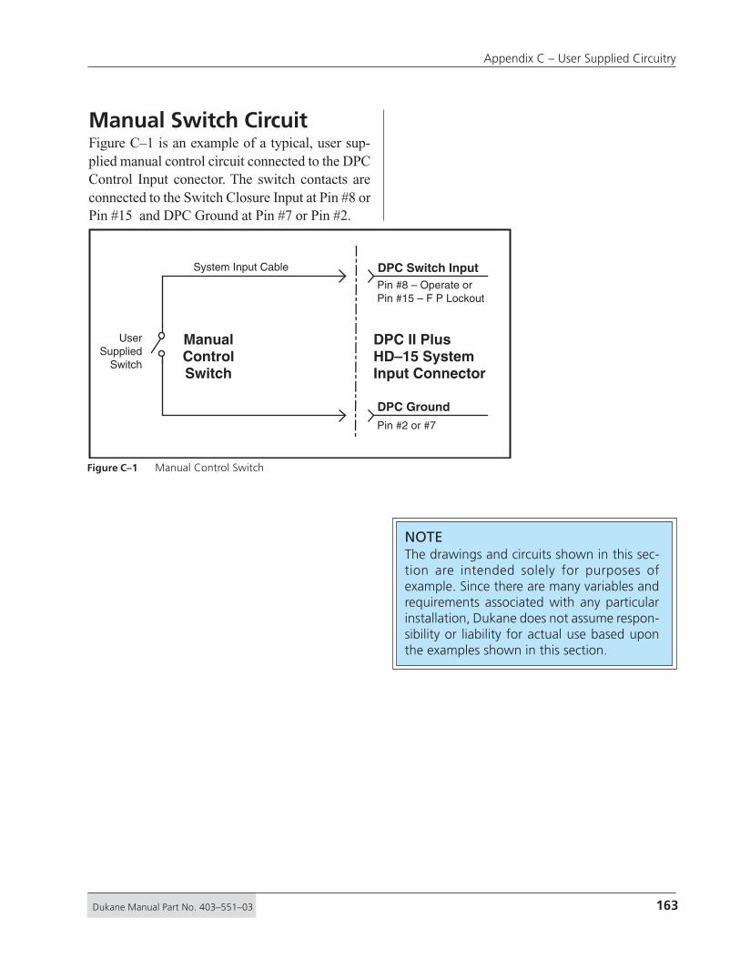
163Dukane Manual Part No. 403–551–03
Appendix C – User Supplied Circuitry
DPC Switch Input
DPC Ground
System Input Cable
ManualControlSwitch
UserSupplied
Switch
Pin #8 – Operate orPin #15 – F P Lockout
Pin #2 or #7
DPC II PlusHD–15 SystemInput Connector
Figure C–1 Manual Control Switch
NOTEThe drawings and circuits shown in this sec-tion are intended solely for purposes ofexample. Since there are many variables andrequirements associated with any particularinstallation, Dukane does not assume respon-sibility or liability for actual use based uponthe examples shown in this section.
Manual Switch CircuitFigure C–1 is an example of a typical, user sup-plied manual control circuit connected to the DPCControl Input conector. The switch contacts areconnected to the Switch Closure Input at Pin #8 orPin #15 and DPC Ground at Pin #7 or Pin #2.

164 Dukane Manual Part No. 403–551–03
Dynamic Process Controller DPC™ II Plus – User’s Manual
User SuppliedRelay
User SuppliedTransistor Driver
Circuit
HD–15System InputConnector
HD–15System InputConnector
HD–15System InputConnector
HD–15System InputConnector
NormallyOpenContact
ToAutomation
ControlSignal
ToAutomation
ControlSignal
ToAutomation
ControlSignal
ToAutomation
ControlSignal
User SuppliedOpto-Coupler
User SuppliedOpen-Collector
Darlington Driver
DPC Switch Input
DPC Ground
�
�
�
�
�
�
�
�
DPC Isolated Input 2 (Figure C–3) orDPC Power Source (Figure C-4)
DPC Ground (Figure C–3) orDPC Isolated Input 1 (Figure C–4)
DPC Isolated Input 2 (Figure C–3) orDPC Power Source (Figure C-4)
DPC Ground (Figure C–3) orDPC Isolated Input 1 (Figure C–4)
DPC Isolated Input 2 (Figure C–3) orDPC Power Source (Figure C-4) or
DPC Ground (Figure C–3) orDPC Isolated Input 1 (Figure C–4) or
DPC Isolated Input 2 (Figure C–3) orDPC Power Source (Figure C-4)
DPC Ground (Figure C–3) orDPC Isolated Input 1 (Figure C–4)
Automation Switch CircuitsFigure C–2 shows examples of various types ofuser supplied automation control circuits con-nected to the DPC Input. These examples can beused in place of the low–side or high–side switchesin Figure C–3 and Figure C–4.
Figure C–2 Automation Control Switches

165Dukane Manual Part No. 403–551–03
Appendix C – User Supplied Circuitry
�
�
+22V
DPC InternalPower Supply
CurrentLimit Circuit250mA max.
Jumper Block SH707Position JU724(Refer to Figure 5–12)
+24V InternalDPC II PlusCircuitry
Optical IsolationCircuit
CurrentLimit Circuit12.5 mA max.
12.5 mA max
4 mA min
Pin #2 or #7
Isolated Input
DPC Ground
Low-SideSwitch
Sinks Currentto Ground
Pin #3 – OperatePin #5 – Press ControlPin #9 – Auto StopUser
SuppliedSwitchCircuitry
Non–Isolated Switch CircuitsCurrent Sink Control CircuitFigure C–3 illustrates an automation control cir-cuit connected to the low side of one of the Iso-lated Automation Inputs. Even though the switchdrives an Opto–Isolator, it is still connected toDPC ground and not isolated. The SH707 jumperblock is in the factory default postion (JU724).Any of the examples in Figure C–2 can be usedin place of the block labeled Low Side SwitchSinks Current To Ground.
Figure C–3 Current Sink Switch

166 Dukane Manual Part No. 403–551–03
Dynamic Process Controller DPC™ II Plus – User’s Manual
DPC II Plus+22V Power
High-SideSwitch
SourcesCurrent
�
�
DPC Ground
+22V
DPC InternalPower Supply
CurrentLimit Circuit250mA max.
Jumper Block SH707Position JU725(Refer to Figure 5–12)
+24V InternalDPC II PlusCircuitry
Optical IsolationCircuit
CurrentLimit Circuit12.5 mA max.
12.5 mA max
4 mA min
Isolated InputPin #3 – OperatePin #5 – Press ControlPin #9 – Auto Stop
Pin #1
UserSuppliedSwitchCircuitry
Pin #2 & Pin #7No Connection
Current Source Control CircuitFigure C–4 illustrates an automation control cir-cuit connected to the highside of one of the Iso-lated Automation Inputs. Even though the switchdrives an Opto–Isolator, it is still connected tothe DPC power source and not isolated. TheSH707 jumper block must be in the JU725 posi-tion (see Figure 5–12). Any of the examples inFigure C–2 can be used in place of the block la-beled High Side Switch Sources Current.
Figure C–4 Current Source Switch

167Dukane Manual Part No. 403–551–03
Appendix C – User Supplied Circuitry
Isolated Switch CircuitIsolated Current Source CircuitFigure C–5 illustrates a fully isolated circuit con-nected to the Isolated Automation Inputs. This re-quires an external power supply to drive the switch.The SH707 jumper block needs to be placed inthe JU726 position (refer to Figure 5–12).
DPC Ground
+22V
DPC InternalPower Supply
CurrentLimit Circuit250mA max.
Pin #2 & Pin #7
Isolated InputHigh–Side
Isolated InputLow–Side
AutomationGround
+5 to +24VAutomationPower Source
IsolatedCurrentSource
Pin #3 – OperatePin #5 – Press ControlPin #9 – Auto Stop
Pin #4 – Iso Common
No Connection
Pin #1No Connection
Jumper Block SH707Position JU726(Refer to Figure 5–12)
+24V InternalDPC II PlusCircuitry
Optical IsolationCircuit
UserSuppliedSwitchCircuitry
CurrentLimit Circuit12.5 mA max.
12.5 mA max
4 mA min
Figure C–5 Isolated Current Source

168 Dukane Manual Part No. 403–551–03
Dynamic Process Controller DPC™ II Plus – User’s Manual
This page intentionally left blank
169Dukane Manual Part No. 403–551–03
Index
INDEX
AAC Power Indicator ....................................................................................... 29AC Power Switch/Breaker ...........................................................19, 25, 30, 39AC Requirements ........................................................................................ 149Afterburst .................................................................................... 73–74, 80, 85Air Circulation .......................................................................................17, 135AMP. ADJUST Key .................................................................................... 34, 82Amplitude Adjust .......................................................................................... 82Amplitude Control Module, Remote ........................................................... 46Amplitude Monitor Output ................................................................... 32, 44Arrow Keys .............................................................................................. 33–34Auto Probe Mode Flowchart ........................................................................ 72Auto Probe, Afterburst ................................................................................. 73 “ “ , Auto Stop Menu ...................................................................... 72 “ “ , Data Entry .......................................................................... 73–74 “ “ , Hold Time ................................................................................. 73 “ “ , Maximum Weld Time............................................................... 72 “ “ , Menu .................................................................................. 72–73 “ “ , Timed ........................................................................................ 73 “ “ , Untimed.................................................................................... 73 “ “ , Weld Method Menu ................................................................ 73Auto Stop Enable .......................................................................................... 69Auto Stop Menu................................................................................ 68, 72, 76Automated Probe System............................................................................. 20Automated Thruster System ........................................................................ 23Automation Circuits ............................................................................163, 164Automation Control Inputs .................................................................... 40–41Automation Equipment ............................................................................... 21Auto–Trac Tuning ............................................................................................ 7
BBad Part Counter......................................................................................... 100Bad Part Limit ................................................................................................ 90Bad Part Status Output ................................................................................. 45Base (Press) Input Cable .................................................................... 23–24, 48Benchtop Placement ..................................................................................... 17Booster ......................................................................................................... 106Booster Gain ................................................................................................ 114Booster Notes .............................................................................................. 114Booster Output End Geometry .................................................................. 114
CCable Color Code .......................................................................................... 41Cable Connections .......................................................... 20–24, 40, 42, 47–49Cable Part Numbers ................................................................................ 21–24
170 Dukane Manual Part No. 403–551–03
Dynamic Process Controller DPC™ II Plus – User’s Manual
Cable Schematics, System ....................................................................... 21–24Cable Troubleshooting ............................................................................... 125CANCEL Key ............................................................................................. 34, 74CE Compliance (Conformité Européene) .......................................... 6, 8, 147Center Depression ....................................................................................... 137Chassis Maintenance ................................................................................... 135Circuits, User Supplied ........................................................................ 161–166Configuration Menu ............................................................................... 57, 65Confirmation Screen ..................................................................................... 35Connectors, Identified ....................................................................19, 39, 125Connector Pinouts............................................................... 40, 42, 48–49, 126Controls, Front Panel .................................................................................... 29Connectors, Rear Panel ................................................19,39, 40, 42, 125, 135Control Inputs ............................................................................................... 41Control Keys .................................................................. 30, 119–121, 128, 135Cooling Air Vents ..................................................................................17, 148Copy Setup .................................................................................................... 99Corrosion, Horn ...........................................................................................137Counter Preset............................................................................................. 101Counter Reset .............................................................................................. 100Crowning, Horn...........................................................................................137Current Loop Connector, 4–20 mA .............................................................. 46Current Loop Fault ........................................................................................ 44Current Loop Transfer Function ................................................................... 46Current Sink Circuit ..................................................................................... 165Current Source Circuit ................................................................................ 166Cycle Press Off Line Menu .......................................................................... 101
DData Entry Menu ........................................................................................... 35DB-25 Connector (System Output) ............................................................... 42Dimensions .................................................................................................. 148Decrement Key .............................................................................................. 34Display, Care of ...........................................................................................135Display, Menu .......................................................................................... 29, 35Display, Status ................................................................................. 31, 19–121Dwell Time (In–Dwell) Status Output .......................................................... 45Dual Pressure Mode ...................................................................................... 76Dukane Press System .................................................................................... 24Dukane Website .......................................................................................... 143
EEmail Addresses, Dukane ........................................................................... 144Emergency Stop Switch ..................................................................20, 25, 119Energy, Welding By ....................................................................................... 70Energy, Definition ......................................................................................... 70Energy Limits ................................................................................................. 89Energy, Min–Max Values .............................................................................. 85Energy Module .......................................... see Power Signal Output Module

171Dukane Manual Part No. 403–551–03
Index
ENTER Key ...............................................................................................34, 77Enter New Setup ........................................................................................... 98Erase Setups................................................................................................... 99Error Messages ...................................................................................... 92, 131Example Setup......................................................................................... 77–81
FFAULT Status Display ............................................................................. 31, 127FCC Compliance.......................................................................................6, 147Features of DPC II Plus .................................................................................... 7Flowcharts .............................. 59, 60, 66, 68, 72, 75, 83, 91, 93, 97, 129, 13040kHz Considerations ................................................................................. 106Frequency Monitor Output .......................................................................... 44Front Panel Controls ........................................................... 29–30, 32–34, 119Front Panel Control Lock ...................................................................... 41, 120Front Panel Displays ................................................................................ 31–32Front panel Maintenance ........................................................................... 135
GGEN. INFO. Key .............................................................................................. 33Good Part Status Output .............................................................................. 45Grounding .................................................................................19, 22, 24, 135Ground–Detect Fixture ................................................................................. 70Ground–Detect Weld Method...................................................................... 70
HHand Probe............................................................................................ 65, 105Hand Probe Mode Flow Chart ..................................................................... 66Hand Probe, Data Entry ................................................................................ 67 “ “ , Timed ....................................................................................... 66 “ “ , Trigger Method ....................................................................... 66 “ “ , Untimed................................................................................... 66 “ “ , Weld Energy ............................................................................ 67 “ “ , Weld Method .......................................................................... 67 “ “ , Weld Time ............................................................................... 67 “ “ , Weld Time, Maximum ............................................................ 67HD–15 Connector (System Input) ................................................................. 40Head Up On Auto Stop ................................................................................. 76Health and Safety Tips .................................................................................. 11HOLD Key ................................................................................................ 33, 81Hold Time ..........................................................................................73, 80, 85Horn ............................................................................................................. 106Horn Assembly ............................................................................................ 112Horn Contact Surfaces ................................................................................ 136Horn Corrosion ............................................................................................ 137Horn Disassembly ........................................................................................ 111Horn Resurfacing ........................................................................................ 138Hot Keys ...................................................................................................34, 81
172 Dukane Manual Part No. 403–551–03
Dynamic Process Controller DPC™ II Plus – User’s Manual
IIncrement Key ............................................................................................... 33In-Dwell Status Output ................................................................................. 45Indicator, AC Power ................................................................................ 19, 30Initiate Mode...........................................................................................76, 78Input Connector, System In ......................................................19, 39, 40, 125Input, Isolated ......................................................................................... 41, 69INPUT TEST Display .......................................................................31, 119, 128INPUT TEST Status Display ............................................................................ 31Internet Site................................................................................................. 143Isolated Inputs ................................................................... 41, 69, Appendix CIsolated Outputs..............................................................................42, 45, 101ISO 9001 Certification ......................................................8, Inside Rear Cover
JJoules, Definition .......................................................................................... 70Jumper Blocks, Internal .................................................................... 52–54, 69Jumper Block, Press Control Module ................................................... 20, 119J901 Thruster Connector .............................................................................. 48J902 Press Base Connector ...................................................................... 48–49
KKey Features of DPC II Plus ............................................................................. 7Keys, Control ................................................................. 30, 119–121, 128, 135Keys, Hot ..................................................................................................34, 81Keys, Menu .................................................................................. 29, 33–34, 77
LLCD Display ......................................................................................29, 35, 135Left Arrow Key .............................................................................................. 33Line Voltage Regulation ................................................................................. 7Limit Definition Flowchart ...............................................................60, 91, 93Limits, Bad ..................................................................................................... 90 “ , Data Entry ......................................................................................... 92 “ , Dual Pressure Mode .......................................................................... 92 “ , Menu.................................................................................................. 90 “ , Min–Max Values ................................................................................ 89 “ , Selection Criteria............................................................................... 90 “ , Single Pressure Mode ....................................................................... 91 “ , Suspect ............................................................................................... 90Load Regulation .............................................................................................. 8
MMaintenance, Scheduled ....................................................................111, 137Master MPC Module ..................................................................................... 51Mating Surfaces (Horn) .............................................................................. 136Maximum Parameter Values ........................................................................ 85Maximum Weld Energy .......................................................................... 72, 75

173Dukane Manual Part No. 403–551–03
Index
Maximum Weld Time ..................................................................67, 70, 71, 79Menu, Confirmation ..................................................................................... 35Menu, Data Entry .......................................................................................... 35Menu, Selection ............................................................................................ 35Menu Flowchart ....................................................................59, 66, 68, 72, 75Menu Keys ................................................................................... 29, 33–34, 77Model Number Coding ............................................................................... 150Mounted Probes.......................................................................................... 111MODE Key .........................................................................................34, 74, 77Mode Menu ............................................................................................. 75, 79Model Number Tag Location ....................................................................... 19MPC Module .................................................................................................. 51MPC Probe, Auto Stop Menu ....................................................................... 68 “ “ , Data Entry ........................................................................... 69–71 “ “ , Maximum Weld Time................................................................ 70 “ “ , Weld Energy Menu ................................................................... 70 “ “ , Weld Method Menu ................................................................. 69 “ “ , Weld Time Menu....................................................................... 69Multi–Probe Control Module ....................................................................... 51Multi–Probe Mode Flow Chart ..................................................................... 68Multiple Probe System Cabling .................................................................... 22
NNavigation Keys (Menu Keys) .................................................... 29, 33–34, 77
OOFF LINE Status Display ........................................................................31, 120OFF LINE Key ................................................................................................. 30ON LINE Status Display ......................................................................... 31, 119ON LINE Key ..........................................................................................30, 119Operational Checkout ........................................................................ 119–120Operating Conditions ................................................................................. 148Operational Control (Thruster) Cable.............................................. 23–24, 49OSHA Compliance ......................................................................................... 12Output Connector, System Status ....................................................19, 39, 42Output, Isolated ...................................................................................... 42, 45OVERLOAD Status Display .............................................................. 31–32. 127OVERLOAD Status Output ............................................................................ 43OVERTEMP Status Display ....................................................................31, 127OVERTEMP Status Output ............................................................................ 43
PParameter Values, Min–Max ........................................................................ 85Part Count, Count Sus/Bad Part ................................................................. 100 “ “ , Menu ........................................................................................ 100 “ “ , Preset ........................................................................................ 101Part Count, Reset ........................................................................................ 100Placement of DPC.......................................................................................... 17

174 Dukane Manual Part No. 403–551–03
Dynamic Process Controller DPC™ II Plus – User’s Manual
Plug–and–Weld ............................................................................................... 7Power, Definition .......................................................................................... 70Power Indicator, AC ................................................................................ 29, 30Power Output Display ............................................................................29, 32Power Output Module ................................................................................. 47Power Signal Output Monitor ..................................................................... 44Power Switch, AC .................................................................................... 25, 30Power Requirements, AC ............................................................................149Press Base Cable Connector...................................................... 23–24, 48, 119Press Control Module ...........................................................................48, 119Press Emergency Stop Switch ............................................................. 101, 119Press Mode Flowchart ................................................................................... 75Press Mode, Afterburst ................................................................................. 80 “ “ , Auto Stop Menu ....................................................................... 76 “ “ , Data Entry ........................................................................... 78–80 “ “ , Head Up On auto Stop ............................................................. 76 “ “ , Hold Time .................................................................................. 80 “ “ , Initiate Mode ...................................................................... 76, 78 “ “ , Maximum Weld Time................................................................ 79 “ “ , Trigger Method ......................................................................... 77 “ “ , Trigger Type ........................................................................76, 78 “ “ , Weld Method ...................................................................... 78, 79 “ “ , Weld Mode ....................................................................76, 78, 79Press Operate Palm Switches ...................................................................... 101Press Setup, Example Program ............................................................... 77–81Press System Cabling ..................................................................................... 24Probe, Auto Menu ........................................................................................ 65 “ , Hand Menu ....................................................................................... 72 “ , ID Selection Bits ................................................................................ 40 “ , Maintenance ................................................................................... 136 “ , MPC Menu ......................................................................................... 68 “ , Operation ........................................................................................ 121 “ , Stacks ....................................................................................... 107–112 “ , Stack Mounting............................................................................... 115 “ , Time Delay Menu .............................................................................. 69 “ , Troubleshooting .............................................................................. 125Process Control Flowchart ............................................................................ 59 “ “ Menu .......................................................... 58–59, 65–66, 84 “ “ Trigger Method Menu ........................................................ 66Process Limits Menu ................................................................................ 60, 90Process Setup Flowchart ......................................................................... 58, 74Process Setup Menu ..........................................................................57, 66, 77Programming Port, Serial ............................................................................. 19Pulse Width Modulation ................................................................................ 7
RRack Mounting DPC ...................................................................................... 18Ready Status Output ..................................................................................... 45Rear Panel Connectors ....................................................................19, 39, 125

175Dukane Manual Part No. 403–551–03
Index
Rear Panel Layout ................................................................................... 19, 39Remote Amplitude Control Module ............................................................ 46Replaceable Tips .................................................................................. 107, 113Resurfacing, Horn ............................................................................... 138–139RFI Considerations ........................................................................................ 13Right Arrow Key............................................................................................ 34RS-232 Serial Port .......................................................................................... 19
SSafety Tips ..................................................................................................... 11Save Setups .................................................................................................... 98Scheduled Maintenance ..................................................................... 111, 137Scrub Time ...............................................................................................71, 85Select Setup ................................................................................................... 98Selection Menu ............................................................................................. 35Self Test ........................................................................................................ 119Setup Files, Remote Selection ...................................................................... 40Setup Utilities Menu ..................................................................................... 98Setup, Copy ................................................................................................... 99 “ , Erase.................................................................................................... 99 “ , Select................................................................................................... 98 “ , Types (Remote) ................................................................................... 98Serial Number Location ................................................................................ 19Serial Programming Port .............................................................................. 19Slave MPC Module ........................................................................................ 51Single Pressure Mode ................................................................................... 76Software Version ........................................................................................... 33Specifications....................................................................................... 148–149Stack Assembly ............................................................................................ 109Stack Inspection .......................................................................................... 136Stack Maintenance ..................................................................................... 136Startup Screen ......................................................................................... 57, 65Status Display .......................................................................................... 29, 31Status Driver Selection Jumper .................................................................... 51Status Output Signals ............................................................................. 42–45Status Output Menu ................................................................................... 101Status Output, Maintained/Pulsed............................................................. 101Status Panel ................................................................................................... 30Stopping The Weld Cycle ............................................................................121Storage Conditions ..................................................................................... 148Studs, Horn & Booster ................................................................................ 108Suspect Part Count ...................................................................................... 100Suspect Part Limit ......................................................................................... 90Switch Circuits, User Supplied ............................................................ 161–166System Cabling ................................................................................ 21–24, 119 “ Control Input Jumper ...................................................................... 53 “ Input Connector ...........................................................19, 39, 40, 125 “ Input Signal Descriptions ................................................................ 41 “ Fault Status Output ......................................................................... 43
176 Dukane Manual Part No. 403–551–03
Dynamic Process Controller DPC™ II Plus – User’s Manual
System Output Connector ................................................................19, 39, 42 “ Power Output Display ..................................................................... 32 “ Test .................................................................................................. 120
TTheory of Operation ................................................................................... 105Telephone Numbers, Dukane ..................................................................... 144Test, Self ....................................................................................................... 119Test, System ................................................................................................. 120TEST Key ........................................................................................30, 120, 128TEST, F P Lock ........................................................................................ 41, 120Thruster Cable Connector .......................................................... 23–24, 48–49Time Delay Menu, Probe .............................................................................. 69Time, Maximum Weld .................................................................67, 70, 71, 79Time, Welding By .................................................................................... 67, 69Timed Probe ............................................................................................ 66, 73Tips, Replaceable ................................................................................. 107, 113Titanium....................................................................................................... 106Top of Stroke ................................................................................................. 23Torque Specifications .................................................................. 107–108, 110Torque Units Conversion ............................................................................ 110Trigger Method Menu ......................................................................66, 75, 77Trigger Type Menu ..................................................................................76, 78Troubleshooting .................................................................................. 125–131
UUltrasonic Output Connector ......................................................... 19, 39, 125Ultrasonic Welding, Theory of ................................................................... 105Universal Power Supply .................................................................................. 8Untimed Probe ........................................................................................ 66, 73Utilities Menu ..........................................................................................61, 98Utilities Flowchart ...................................................................................61, 97
VValues, Parameter Min–Max ........................................................................ 85Vents, Cooling Air ...................................................................17, 31, 135, 148Vise, Booster Clamping ............................................................................... 113Version of DPC Firmware.............................................................................. 57
WWarranty, Domestic .................................................................................... 153Warranty, International .............................................................................. 154Warranty, Tooling ....................................................................................... 154Website, Dukane ......................................................................................... 143Weld By Energy ............................................................................................. 70Weld By Time...........................................................................................67, 69

177Dukane Manual Part No. 403–551–03
Index
Weld Cycle Data ................................................................................ 57, 65, 81Weld Energy ......................................................................................67, 70, 79Weld Method .................................................................................... 67, 69, 78Weld Mode .............................................................................................. 75, 79WELD P1 Key ........................................................................................... 33, 82WELD P2 Key ........................................................................................... 34, 82Weld Time..........................................................................................67, 69, 78Weld Time Min–Max Values ......................................................................... 85Weld Time Limits ........................................................................................... 89Wrench, Horn & Booster ............................................................................107

178 Dukane Manual Part No. 403–551–03
Dynamic Process Controller DPC™ II Plus – User’s Manual
This page intentionally left blank

Dukane ISOISO CERTIFICATIONDukane chose to become ISO 9001:2000 cer-tified in order to demonstrate to our customersour continuing commitment to being a qualityvendor. By passing its audit, Dukane can as-sure you that we have in place a well–definedand systematic approach to quality design,manufacturing, delivery and service. This cer-tificate reinforces Dukane's status as a qualityvendor of technology and products.
To achieve ISO 9001:2000 certification, youmust prove to one of the quality system regis-trar groups that you meet three requirements:1. Leadership2. Involvement3. Quality in Line Organizations and Quality
System Infrastructure.
The ISO 9001:2000 standard establishes a mini-mum requirement for these requirements andstarts transitioning the company from a traditionalinspection–oriented quality system to one basedon partnership for continuous improvement. Thisconcept is key in that Dukane no longer focuseson inspection, but on individual processes.
Dukane's quality management system is basedon the following three objectives:1. Customer oriented quality. The aim is to
improve customer satisfaction.2. Quality is determined by people. The aim
is to improve the internal organization andcooperation between staff members.
3. Quality is a continuous improvement. Theaim is to continuously improve the internalorganization and the competitive position.
Dukane products are manufactured in ISOregistered facilities
ISO 9001:2000C E R T I F I E D

40355103Dukane Corporation • Ultrasonics Division • 2900 Dukane Drive • St. Charles, Illinois 60174 USA • TEL (630) 797-4900 • FAX (630) 797–4949
Part No. 403–551–03
Printed in the United States of America$100.00
DPC–II Plus User's Manual
www.dukcorp.com/us
1
2
3
5
5
3
6
6
Regional OfficeFilm & Fabric
Appl. Lab
Engineering Lab
Tooling Lab
Tooling LabWestern Serv.Cntr.
MexicoSales &Serv.Cntr.
Main Serv.Cntr.
AutomotiveAppl. Lab
Corporate Officeand Training Center
Application Laboratory
Service Center
§
§
§
4
REGIONAL OFFICESNortheast RegionRocco Telese14 Delmar Drive – Suite 6BBrookfield, CT 06084(203) 740–0089
Central RegionJason Barton4424 Aicholtz Road – Suite GCincinnati, OH 45245(513) 752–8803
Automotive RegionRaymond LaFlamme11235 Stark RoadLivonia, MI 48150(734) 513–4038
Midwest RegionJerry Wibben2900 Dukane DriveSt. Charles, IL 60174(630) 797–4921
Western Region & AlaskaJames Jackstein162 East Manilla DriveDraper, UT 84020(801) 523–6191
Mexico & CaribbeanNelson Romero2900 Dukane DriveSt. Charles, IL 60174(630) 797–4915
Mexico Service CenterAlejandro (Alex) JuarezDukane CorporationVulcano No. 1618Col. Nueva Linda VistaGuadalupe NL CP 67110 MexicoTEL 011–52–81–8364–9313
�
�
�
�
�
�
§
DUKANE CORPORATIONWHO ARE WE?
We are plastic welding technoligists. We are scientists.We are employees and businessmen. We are instructors.
We are engineers. We are specialists in electronicsand experts in plastic assembly. We are salesmen. We do
basic research and we manufacture machines.We are problem solvers and we are technical advisors
We Are Your Partners.