EZmoto V3 - Adaptive Modules V3 FRONT VIEW REAR VIEW Product description Rev. 10 – 17/06/2014 2...
11
1 EZmoto V3 FRONT VIEW REAR VIEW Product description Rev. 10 – 17/06/2014
Transcript of EZmoto V3 - Adaptive Modules V3 FRONT VIEW REAR VIEW Product description Rev. 10 – 17/06/2014 2...
1
EZmoto V3
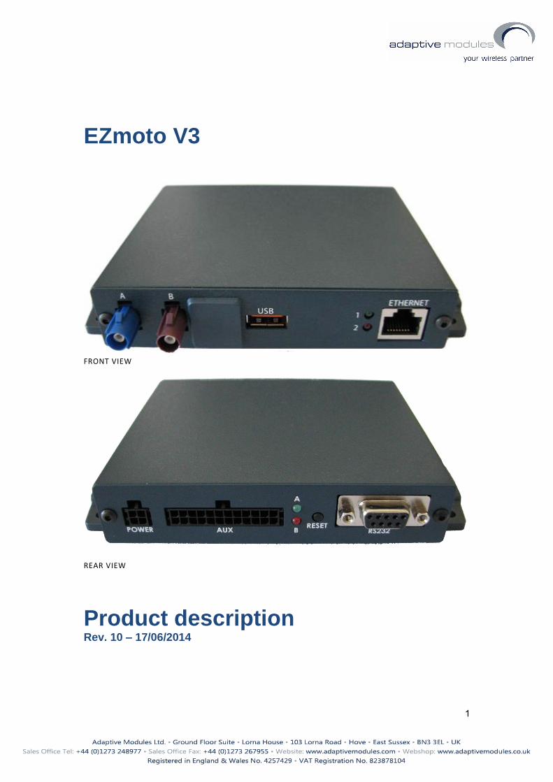
FRONT VIEW
REAR VIEW
Product description Rev. 10 – 17/06/2014

2
Contents 1. Overview ................................................................................................................................ 3
2. Hardware Interface Description ............................................................................................ 3
2.1 Main features of the EZmoto .......................................................................................... 3
2.2 Hardware block diagram ................................................................................................. 4
2.3 Internal Hardware connection ........................................................................................ 5
3. Interface description ............................................................................................................. 6
3.1 Molex 4 pin connector – Power connector ..................................................................... 6
3.1.1 Power Supply ............................................................................................................ 6
3.1.2 Supply voltage requirements ................................................................................... 7
3.2 USB CONNECTOR ............................................................................................................. 7
3.3 FAKRA CONNECTORS ....................................................................................................... 7
3.4 RJ45 – ETHERNET CONNECTOR ....................................................................................... 7
3.5 SIM DRAWER ................................................................................................................... 7
3.6 RS232 Interface ............................................................................................................... 8
5. Mechanical Characteristics .................................................................................................. 10
5.1 General mechanical description .................................................................................... 10
5.2 Environmental requirements ........................................................................................ 10
5.3 Protection class ............................................................................................................. 10
5.4 RoHS compliance ........................................................................................................... 10
6. SAFETY RECOMMANDATIONS ............................................................................................. 11
7. Two Years Limited Warranty ............................................................................................... 11

3
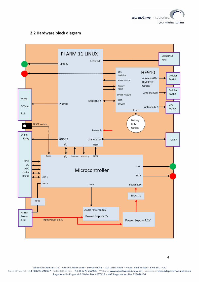
1. Overview The mobile router EZmoto is a complete 3G Cellular Router solution (with GPS) that allows Ethernet-based devices to utilize a cellular data account. EZmoto based on Telit HE910 module and ARM 11.
2. Hardware Interface Description
2.1 Main features of the EZmoto
Feature Implementation
Incorporates Telit HE910 module The Telit module handles all GSM/UMTS GPS
Frequency bands GSM: 850/900/1800/1900/2100MHz UMTS/HSPA+: 800/850/900/1700/1900/2100MHz
Incorporates ARM 11 Introduced the ARM11 with 512Mb SDRAM LINUX operating system, SD card
Power supply Single supply voltage 6V DC to 55V DC connector 4 pin micro-fit 3mm
Communication Ethernet RJ45 connector RS232 connector D-Type 9 pin Connector USB Type A
Antennas UMTS GPS via FAKRA connectors
GPIO 24 pin connector Input and output control
4
2.2 Hardware block diagram
HE910
USB
Device
PI ARM 11 LINUX
Power 5v
Antenna GSM
Antenna GPS
24 pin
Relay
GPIO
OC
ADC
1Wire
RS232
RS485
Power
4 pin
USB A
USB HOST A
USB HOST B
RS232
D-Type
9 pin
PI UART
Cellular
FAKRA
GPS
FAKRA
GPIO 27
LED
Cellular
ETHERNET
RJ45 ETHERNET
Microcontroller
Power Supply 4.2V
Power Supply 5V
Input Power 6-55v
Power 3.3V
LDO 3.3V
Enable Power supply
I²C
Watchdog Interrupt
RS485
UART 2
UART 1
I²C
Control
RESET switch
Reset
LED A
LED B
Antenna GSM
DIVERSTIY
Option
Cellular
FAKRA
RESET
RESET
Power Monitor
ON/OFF
RESET
UART HE910
GPIO 25
Battery
Li 3V
Option
RTC
5
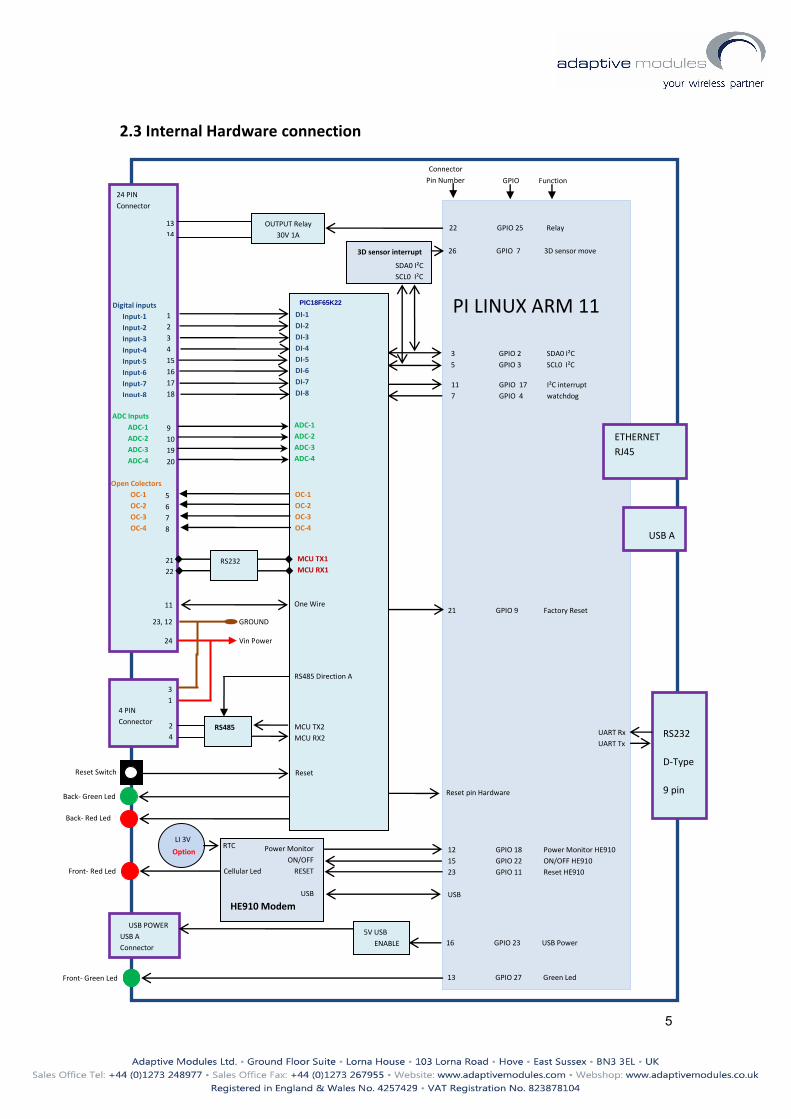
2.3 Internal Hardware connection
PI LINUX ARM 11
OUTPUT Relay
30V 1A
13
14
22 GPIO 25 Relay
11 GPIO 17 I²C interrupt
7 GPIO 4 watchdog
13 GPIO 27 Green Led
Front- Green Led
Reset Switch
3 GPIO 2 SDA0 I²C
5 GPIO 3 SCL0 I²C
USB POWER
USB A
Connector
Vin Power
GROUND
24 PIN
Connector
Connector
Pin Number
p
Power Monitor
ON/OFF
RESET
USB
HE910 Modem
12 GPIO 18 Power Monitor HE910
15 GPIO 22 ON/OFF HE910
23 GPIO 11 Reset HE910
USB
16 GPIO 23 USB Power
5V USB
ENABLE
24
23, 12
GPIO Function
PIC18F65K22
One Wire
11
1
2
3
4
15
16
17
18
DI-1
DI-2
DI-3
DI-4
DI-5
DI-6
DI-7
DI-8
9
10
19
20
5
6
7
8
ADC Inputs
ADC-1
ADC-2
ADC-3
ADC-4
OC-1
OC-2
OC-3
OC-4
MCU TX1
MCU RX1
21
22
RS232
2
4 RS485
3
1
RS485 Direction A
4 PIN
Connector
UART Rx
UART Tx
Digital inputs
Input-1
Input-2
Input-3
Input-4
Input-5
Input-6
Input-7
Input-8
ADC-1
ADC-2
ADC-3
ADC-4
Open Colectors
OC-1
OC-2
OC-3
OC-4
MCU TX2
MCU RX2
21 GPIO 9 Factory Reset
Reset
Reset pin Hardware
26 GPIO 7 3D sensor move
3D sensor interrupt
SDA0 I²C
SCL0 I²C
Front- Red Led
Cellular Led
Green
Back- Green Led
Back- Red Led
ETHERNET
RJ45
RS232
D-Type
9 pin
USB A
RTC
LI 3V
LI
Option
6
4 3
2 1
3. Interface description
3.1 Molex 4 pin connector – Power connector
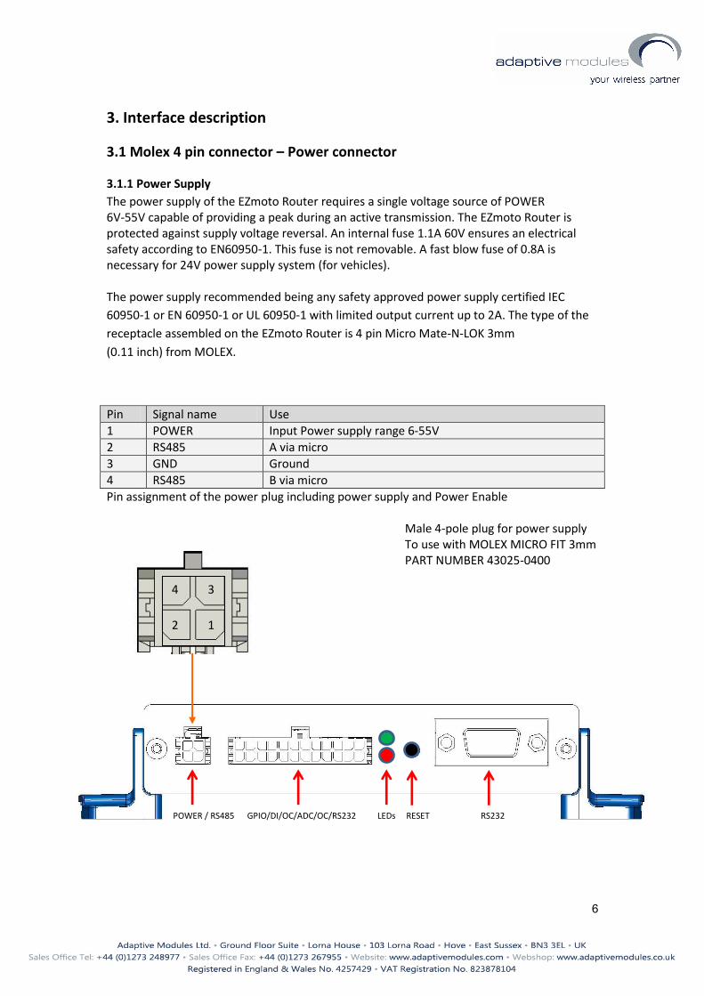
3.1.1 Power Supply
The power supply of the EZmoto Router requires a single voltage source of POWER 6V-55V capable of providing a peak during an active transmission. The EZmoto Router is protected against supply voltage reversal. An internal fuse 1.1A 60V ensures an electrical safety according to EN60950-1. This fuse is not removable. A fast blow fuse of 0.8A is necessary for 24V power supply system (for vehicles). The power supply recommended being any safety approved power supply certified IEC
60950-1 or EN 60950-1 or UL 60950-1 with limited output current up to 2A. The type of the
receptacle assembled on the EZmoto Router is 4 pin Micro Mate-N-LOK 3mm
(0.11 inch) from MOLEX.
Pin Signal name Use
1 POWER Input Power supply range 6-55V
2 RS485 A via micro
3 GND Ground
4 RS485 B via micro
Pin assignment of the power plug including power supply and Power Enable Male 4-pole plug for power supply To use with MOLEX MICRO FIT 3mm PART NUMBER 43025-0400
POWER / RS485 GPIO/DI/OC/ADC/OW/RS232 LEDs RESET RS232
POWER / RS485 GPIO/DI/OC/ADC/OC/RS232 LEDs RESET RS232
7
3.1.2 Supply voltage requirements
The DC power supply must be connected to the POWER input: • Input voltage range 6 - 55V DC • Nominal Voltage 12V DC • Power Supply current rating: max. 2A @12V • Power Supply ripple: max. 120mV • Input current in idle mode: 200mA @ 12V • Input average current in communication mode: 500mA @ 12V
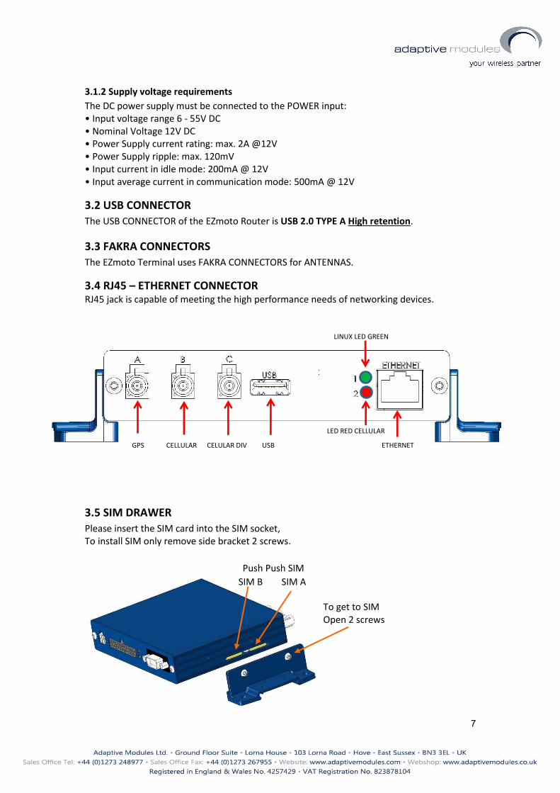
3.2 USB CONNECTOR
The USB CONNECTOR of the EZmoto Router is USB 2.0 TYPE A High retention.
3.3 FAKRA CONNECTORS
The EZmoto Terminal uses FAKRA CONNECTORS for ANTENNAS.
3.4 RJ45 – ETHERNET CONNECTOR
RJ45 jack is capable of meeting the high performance needs of networking devices.
3.5 SIM DRAWER
Please insert the SIM card into the SIM socket, To install SIM only remove side bracket 2 screws.
GPS CELLULAR CELULAR DIV USB ETHERNET
LINUX LED GREEN
LED RED CELLULAR
Push Push SIM
SIM B SIM A
To get to SIM Open 2 screws
8
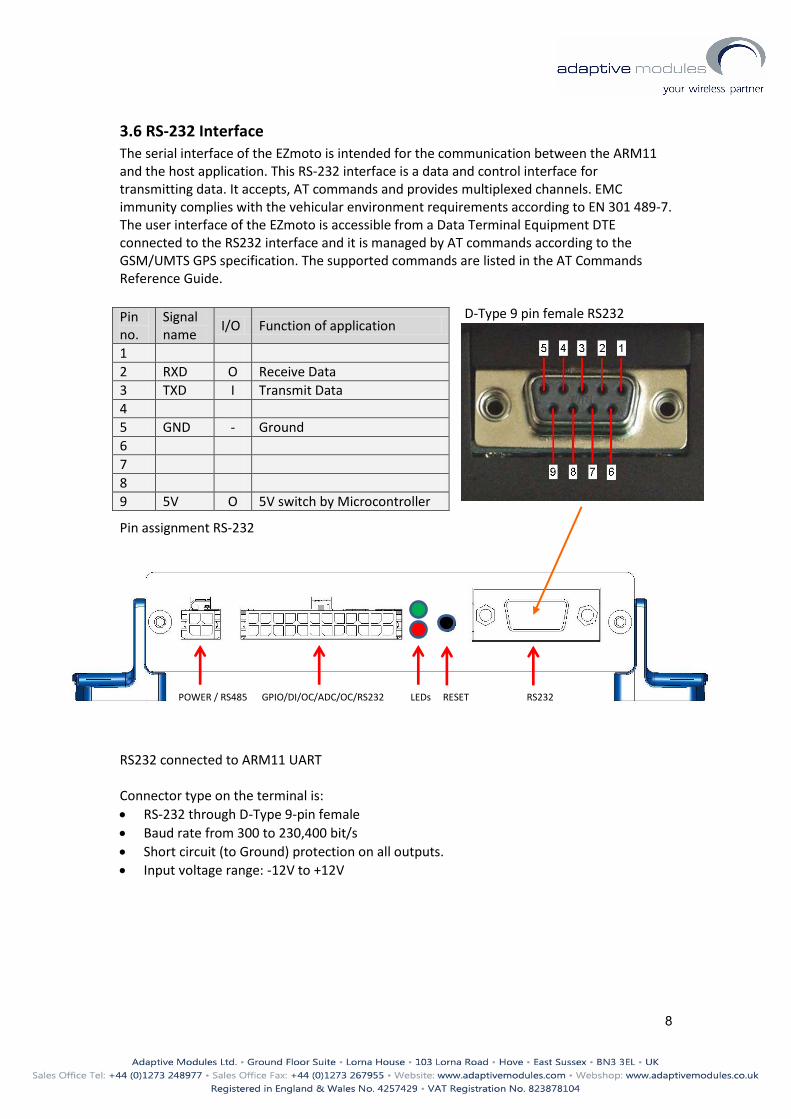
3.6 RS-232 Interface
The serial interface of the EZmoto is intended for the communication between the ARM11 and the host application. This RS-232 interface is a data and control interface for transmitting data. It accepts, AT commands and provides multiplexed channels. EMC immunity complies with the vehicular environment requirements according to EN 301 489-7. The user interface of the EZmoto is accessible from a Data Terminal Equipment DTE connected to the RS232 interface and it is managed by AT commands according to the GSM/UMTS GPS specification. The supported commands are listed in the AT Commands Reference Guide.
Pin assignment RS-232 RS232 connected to ARM11 UART Connector type on the terminal is:
RS-232 through D-Type 9-pin female
Baud rate from 300 to 230,400 bit/s
Short circuit (to Ground) protection on all outputs.
Input voltage range: -12V to +12V
Pin no.
Signal name
I/O Function of application
1
2 RXD O Receive Data
3 TXD I Transmit Data
4
5 GND - Ground
6
7
8
9 5V O 5V switch by Microcontroller
POWER / RS485 GPIO/DI/OC/ADC/OC/RS232 LEDs RESET RS232
D-Type 9 pin female RS232
9
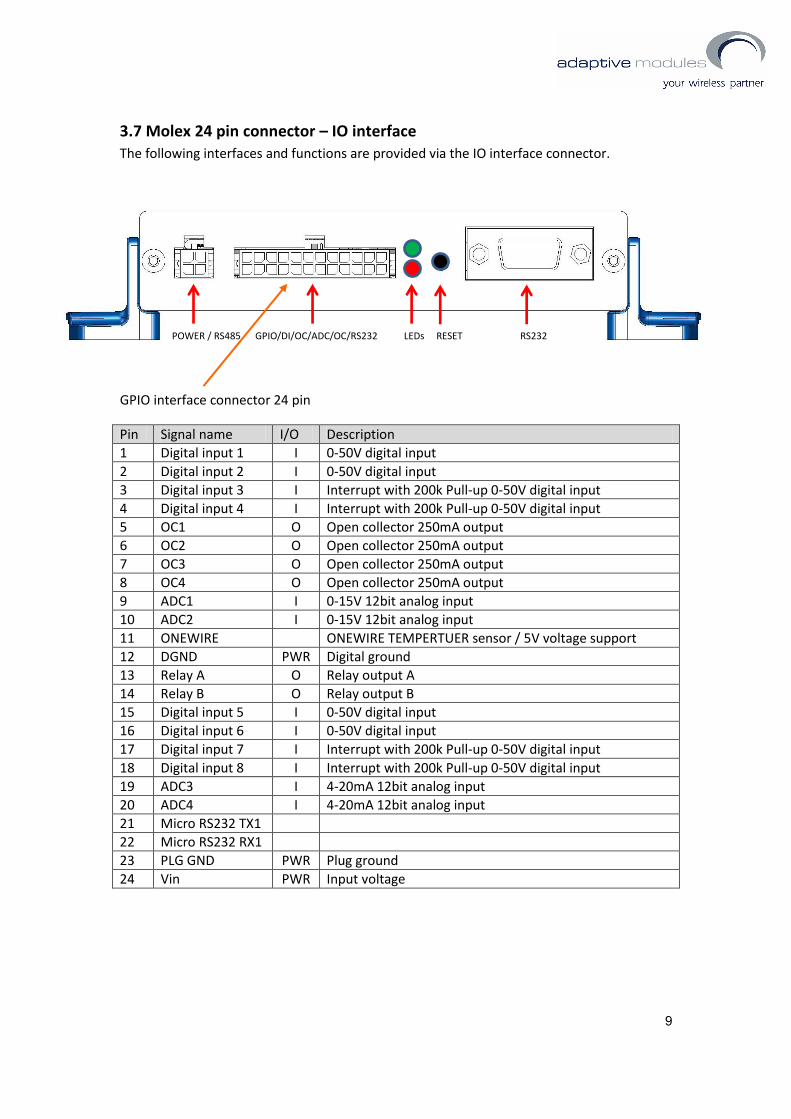
3.7 Molex 24 pin connector – IO interface
The following interfaces and functions are provided via the IO interface connector.
GPIO interface connector 24 pin
Pin Signal name I/O Description
1 Digital input 1 I 0-50V digital input
2 Digital input 2 I 0-50V digital input
3 Digital input 3 I Interrupt with 200k Pull-up 0-50V digital input
4 Digital input 4 I Interrupt with 200k Pull-up 0-50V digital input
5 OC1 O Open collector 250mA output
6 OC2 O Open collector 250mA output
7 OC3 O Open collector 250mA output
8 OC4 O Open collector 250mA output
9 ADC1 I 0-15V 12bit analog input
10 ADC2 I 0-15V 12bit analog input
11 ONEWIRE ONEWIRE TEMPERTUER sensor / 5V voltage support
12 DGND PWR Digital ground
13 Relay A O Relay output A
14 Relay B O Relay output B
15 Digital input 5 I 0-50V digital input
16 Digital input 6 I 0-50V digital input
17 Digital input 7 I Interrupt with 200k Pull-up 0-50V digital input
18 Digital input 8 I Interrupt with 200k Pull-up 0-50V digital input
19 ADC3 I 4-20mA 12bit analog input
20 ADC4 I 4-20mA 12bit analog input
21 Micro RS232 TX1
22 Micro RS232 RX1
23 PLG GND PWR Plug ground
24 Vin PWR Input voltage
POWER / RS485 GPIO/DI/OC/ADC/OC/RS232 LEDs RESET RS232
11
5. Mechanical Characteristics
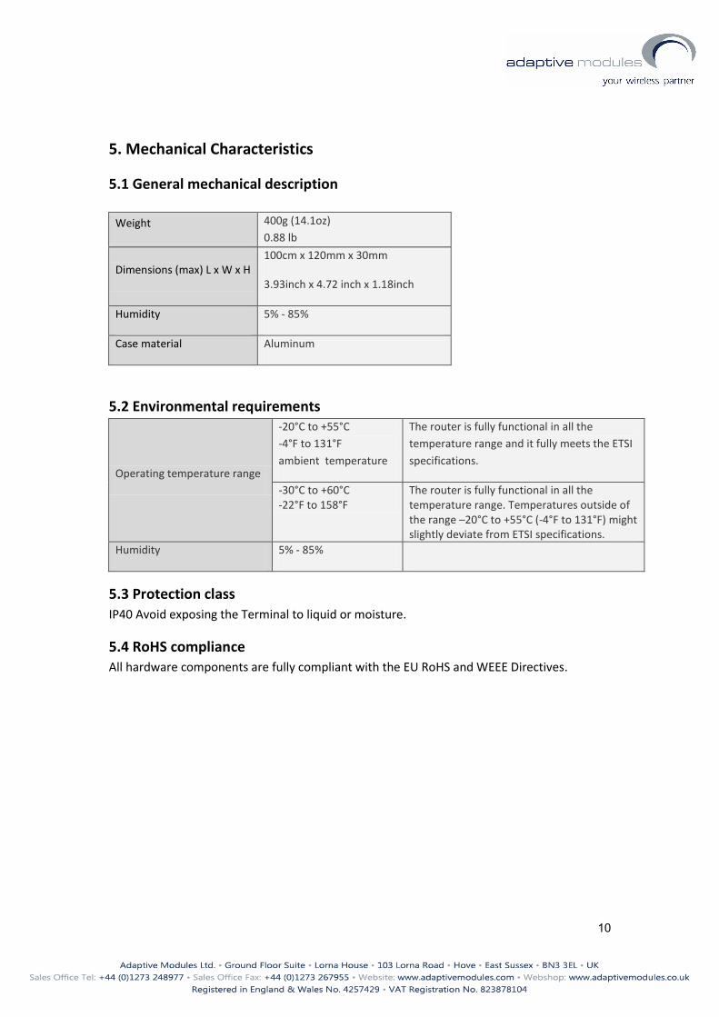
5.1 General mechanical description
Weight 400g (14.1oz)
0.88 lb
Dimensions (max) L x W x H 100cm x 120mm x 30mm
3.93inch x 4.72 inch x 1.18inch
Humidity 5% - 85%
Case material Aluminum
5.2 Environmental requirements
Operating temperature range
-20°C to +55°C
-4°F to 131°F
ambient temperature
The router is fully functional in all the
temperature range and it fully meets the ETSI
specifications.
-30°C to +60°C -22°F to 158°F
The router is fully functional in all the temperature range. Temperatures outside of the range –20°C to +55°C (-4°F to 131°F) might slightly deviate from ETSI specifications.
Humidity 5% - 85%
5.3 Protection class
IP40 Avoid exposing the Terminal to liquid or moisture.
5.4 RoHS compliance
All hardware components are fully compliant with the EU RoHS and WEEE Directives.

11
6. SAFETY RECOMMANDATIONS READ CAREFULLY
1. The unit does not provide protection from lightning and surge. For outdoor installation
use outdoor nonmetallic case safety approved according UL 50. Additionally you should
provide protection from lightning and over voltage according National code.
2. Be sure the use of this product is allowed in the country and in the environment
required. The use of this product may be dangerous and has to be avoided in the following
areas: Where it can interfere with other electronic devices in environments such as
hospitals, airports, aircrafts, etc. Where there is risk of explosion such as gasoline stations,
oil refineries, etc. It is responsibility of the user to enforce the country regulation and the
specific environment regulation. Do not disassemble the product; any mark of tampering
will compromise the warranty validity. We recommend following the instructions of the
hardware user guides for a correct wiring of the product. The product has to be supplied
with a stabilized voltage source and the wiring has to be conforming to the security and
fire prevention regulations. The product has to be handled with care, avoiding any contact
with the pins because electrostatic discharges may damage the product itself. Same
cautions have to be taken for the SIM, checking carefully the instruction for its use. Do not
insert or remove the SIM when the product is in power saving mode. The system
integrator is responsible of the functioning of the final product; therefore, care has to be
given to the external components of the unit, as well as of any project or installation issue,
because the risk of disturbing the GSM network or external devices or having impact on
the security. Should there be any doubt, please refer to the technical documentation and
the regulations in force. Every unit has to be equipped with a proper antenna with specific
characteristics. The antenna has to be installed with care in order to avoid any
interference with other electronic devices and has to guarantee a minimum distance from
the body (20 cm/8”). In case this requirement cannot be satisfied, the system integrator
should assess the final product against the SAR regulation. The European Community
provides some Directives for the electronic equipment introduced on the market. All the
relevant information available on the European Community website:
http://europa.eu.int/comm/enterprise/rtte/dir99-5.htm The text of the Directive 99/05
regarding telecommunication equipment is available, while the applicable Directives (Low
Voltage and EMC) are available at:
http://europa.eu.int/comm/enterprise/electr_equipment/index_en.htm