Downsized microminiature Linear Split Stirling Cryogenic ... linear cooler for high... · Split...
13
Split Stirling linear cryogenic cooler for a new generation of high temperature infrared imagers A Veprik, S Zehtzer and N Pundak Ricor, Cryogenic and Vacuum Systems, En Harod, 18960, Israel ABSTRACT Split linear cryocoolers find use in a variety of infrared equipment installed in airborne, heliborne, marine and vehicular platforms along with hand held and ground fixed applications. An upcoming generation of portable, high-definition night vision imagers will rely on the high-temperature infrared detectors, operating at elevated temperatures, ranging from 95K to 200K, while being able to show the performance indices comparable with these of their traditional 77K competitors. Recent technological advances in industrial development of such high-temperature detectors initialized attempts for developing compact split Stirling linear cryogenic coolers. Their known advantages, as compared to the rotary integral coolers, are superior flexibility in the system packaging, constant and relatively high driving frequency, lower wideband vibration export, unsurpassed reliability and aural stealth. Unfortunately, such off-the-shelf available linear cryogenic coolers still cannot compete with rotary integral rivals in terms of size, weight and power consumption. Ricor developed the smallest in the range, 1W@95K, linear split Stirling cryogenic cooler for demanding infrared applications, where power consumption, compactness, vibration, aural noise and ownership costs are of concern. Keywords: high temperature infrared detector, compact infrared imager, split Stirling linear cooler, vibration, aural noise, reliability. 1. INTRODUCTION Infrared (IR) imagers play a vital role in the modern tactics of carrying out surveillance, reconnaissance, targeting and navigation operations. By converting the thermal battlefield into dynamic visual imagery, such equipment dramatically enhances the observation and command control capabilities of the leaders of combat infantry and Special Forces. In spite of the recent advances and widespread use of uncooled infrared detectors, it is still generally accepted that the “best technology for true IR heat detection is the cooled detector” [1]. They are superior to the uncooled competitors in terms of working ranges, resolution and ability in detecting/tracking fast moving objects in dynamic infrared scenes. The superior performance of such imagers is achieved by using novel optronic technologies along with maintaining the IR focal plane arrays (FPA) at cryogenic temperatures (77K, typically) using microminiature Stirling cycle cryogenic coolers. Over the past few years industrial progress has led to the development of a new InAlSb diode technology relying on Antimonide Based Compound Semiconductors (ABCS), offering lower dark currents or higher operating temperatures (being in the 100K region) [2]. The SWIR MCT technology [3] offers the possibility of operating a FPA at even higher temperatures, in excess of 200 K. The authors of [4] report on a 320×256 middle-wavelength infrared focal plane array based on InAs quantum-dot/InGaAs quantum-well/InAlAs barrier detector operating at temperatures of up to 200K. The direct benefits of using such high temperature IR FPAs are the lowering of the cooling constraints resulting in a simplified system design, using smaller and more cost effective, long life cryocoolers which typically consume less electrical power and show faster cool-down times. Traditionally, integral rotary cryogenic coolers were used for maintaining the, such as above, IR FPA at optimal cryogenic temperatures. As compared to their military off-the-shelf linear competitors they were lighter, more compact and normally had better electromechanical performance. However, their inherent drawbacks, such as high wideband vibration export and limited lifespan spurred the development of the microminiature linear Stirling cryogenic coolers. These novel, long-life, acoustically and dynamically quiet cryogenic coolers, while being superior in many respects, need to be comparable to the above rotary cryocoolers in terms of bulk, power consumption and ownership costs. An additional advantage of the linear cryocoolers, as compared with their rotary rivals, should be that, at least in theory, they might operate at elevated driving frequencies without affecting their overall life span. Unfortunately, such coolers are still not off-the-shelf available; the existing linear tactical coolers are too oversized/overweight and power-thirsty for the above purposes.
Transcript of Downsized microminiature Linear Split Stirling Cryogenic ... linear cooler for high... · Split...
Split Stirling linear cryogenic cooler for a new generation of high
temperature infrared imagers
A Veprik, S Zehtzer and N Pundak
Ricor, Cryogenic and Vacuum Systems, En Harod, 18960, Israel
ABSTRACT
Split linear cryocoolers find use in a variety of infrared equipment installed in airborne, heliborne, marine and vehicular
platforms along with hand held and ground fixed applications. An upcoming generation of portable, high-definition night
vision imagers will rely on the high-temperature infrared detectors, operating at elevated temperatures, ranging from 95K
to 200K, while being able to show the performance indices comparable with these of their traditional 77K competitors.
Recent technological advances in industrial development of such high-temperature detectors initialized attempts for
developing compact split Stirling linear cryogenic coolers. Their known advantages, as compared to the rotary integral
coolers, are superior flexibility in the system packaging, constant and relatively high driving frequency, lower wideband
vibration export, unsurpassed reliability and aural stealth. Unfortunately, such off-the-shelf available linear cryogenic
coolers still cannot compete with rotary integral rivals in terms of size, weight and power consumption.
Ricor developed the smallest in the range, 1W@95K, linear split Stirling cryogenic cooler for demanding infrared
applications, where power consumption, compactness, vibration, aural noise and ownership costs are of concern.
Keywords: high temperature infrared detector, compact infrared imager, split Stirling linear cooler, vibration, aural
noise, reliability.
1. INTRODUCTION
Infrared (IR) imagers play a vital role in the modern tactics of carrying out surveillance, reconnaissance, targeting and
navigation operations. By converting the thermal battlefield into dynamic visual imagery, such equipment dramatically
enhances the observation and command control capabilities of the leaders of combat infantry and Special Forces.
In spite of the recent advances and widespread use of uncooled infrared detectors, it is still generally accepted that the
“best technology for true IR heat detection is the cooled detector” [1]. They are superior to the uncooled competitors in
terms of working ranges, resolution and ability in detecting/tracking fast moving objects in dynamic infrared scenes.
The superior performance of such imagers is achieved by using novel optronic technologies along with maintaining the
IR focal plane arrays (FPA) at cryogenic temperatures (77K, typically) using microminiature Stirling cycle cryogenic
coolers.
Over the past few years industrial progress has led to the development of a new InAlSb diode technology relying on
Antimonide Based Compound Semiconductors (ABCS), offering lower dark currents or higher operating temperatures
(being in the 100K region) [2]. The SWIR MCT technology [3] offers the possibility of operating a FPA at even higher
temperatures, in excess of 200 K. The authors of [4] report on a 320×256 middle-wavelength infrared focal plane array
based on InAs quantum-dot/InGaAs quantum-well/InAlAs barrier detector operating at temperatures of up to 200K.
The direct benefits of using such high temperature IR FPAs are the lowering of the cooling constraints resulting in a
simplified system design, using smaller and more cost effective, long life cryocoolers which typically consume less
electrical power and show faster cool-down times.
Traditionally, integral rotary cryogenic coolers were used for maintaining the, such as above, IR FPA at optimal
cryogenic temperatures. As compared to their military off-the-shelf linear competitors they were lighter, more compact
and normally had better electromechanical performance. However, their inherent drawbacks, such as high wideband
vibration export and limited lifespan spurred the development of the microminiature linear Stirling cryogenic coolers.
These novel, long-life, acoustically and dynamically quiet cryogenic coolers, while being superior in many respects,
need to be comparable to the above rotary cryocoolers in terms of bulk, power consumption and ownership costs. An
additional advantage of the linear cryocoolers, as compared with their rotary rivals, should be that, at least in theory, they
might operate at elevated driving frequencies without affecting their overall life span. Unfortunately, such coolers are
still not off-the-shelf available; the existing linear tactical coolers are too oversized/overweight and power-thirsty for the
above purposes.
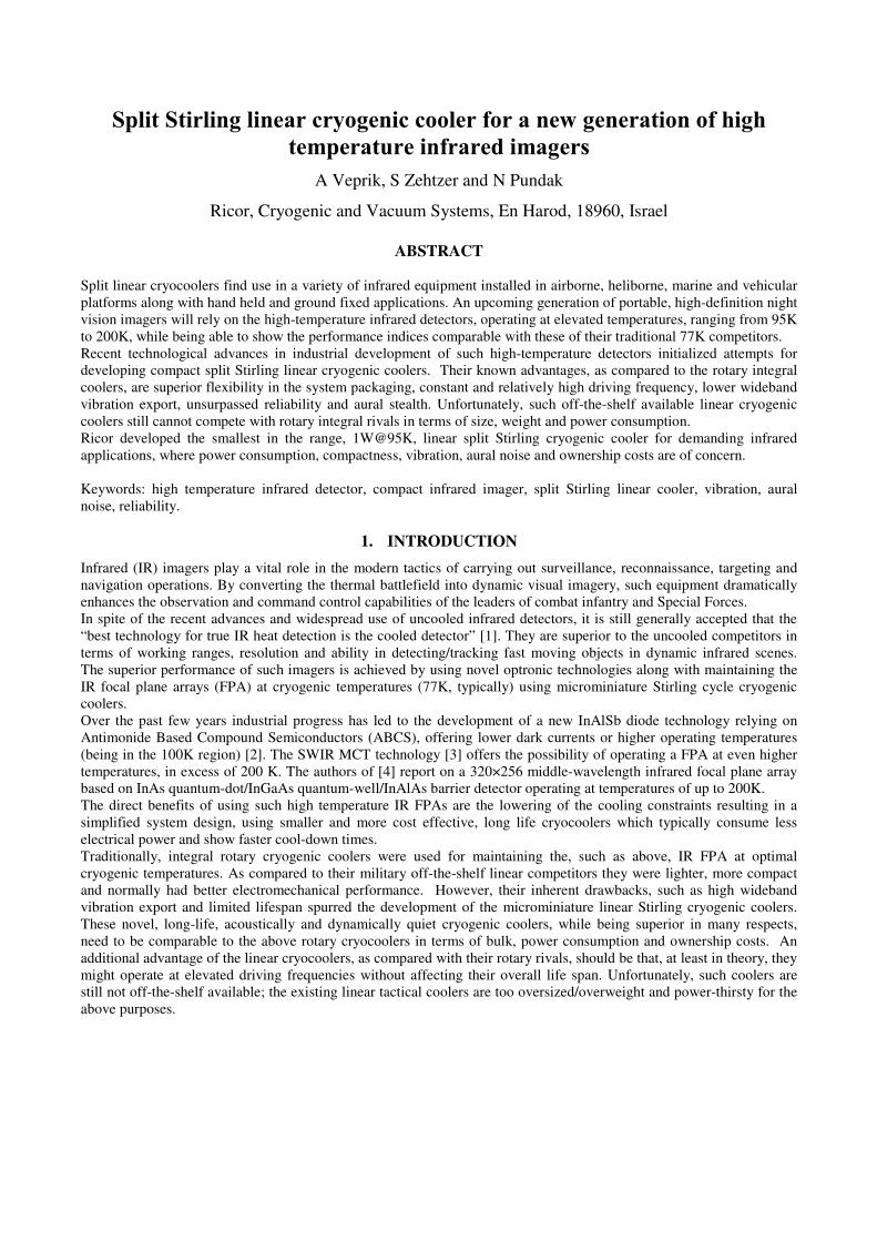
The authors report on the successful development of a novel Ricor
model K527 microminiature 1W@95K split Stirling linear
cryogenic cooler [5], which was designed to provide cryogenic
cooling to a wide range of forthcoming infrared imagers, where
power consumption, compactness, vibration, aural noise and
ownership costs are of concern. The cooler, as shown in Figure 1,
comprises "moving magnet" resonant piston compressor and
pneumatically driven expander connected by a flexible transfer
line .
2. K527 EXPANDER UNIT
The expander unit comprises a "mass-spring", pneumatically
driven displacer-regenerator, as is wide accepted across the
industry. As is known, it is favorable to design such a displacer-
regenerator so that to operate it at or near its resonant frequency.
The first benefit of such a resonant tuning is that the displacer
stroke reaches its maximum at given pneumatic force delivered by the compressor, or alternatively, the desired displacer
stroke may be obtained at minimum pneumatic force delivery. The second benefit is that tuning the displacer to resonate
delivers almost automatically the desired 90º phase lag between the pressure pulses arriving through the transfer line
from the compression space and the displacer motion, as needed for producing maximum cooling effect [6]. The above
two benefits contributes essentially to increasing the displacer's expansion work at given acoustic work delivered by a
compressor. Resulting from this is improved heat pumping effect from the expansion space to which the heat payload is
thermally linked. Since the spring effect of equivalent gaso-dynamic visco-elastic loading in expander is negligibly
small, the inertia of the moving assembly and the equivalent elasticity of the above-mentioned spring define the
closeness to the resonance condition. There are two different approaches to forming the above "spring" component. In
the first approach, helical wire spring or, alternatively, two counter-facing preloaded helical wire springs are arranged as
to link the stationary housing with the movable displacer-regenerator assembly. Using mechanical spring yields compact
design and convenient resonant tuning which appears to be almost independent on environmental temperature. The
inherent disadvantages of such a design are unreliable mechanical spring connection, radiation of acoustic noise, tiny
metal debris generation and, most important, exertion of large side forces on dynamic seals leading to excessive friction,
parasitic losses, tear and wear.
In another implementation, a "pneumatic pillow" [6] may be formed by the plunger tail cyclically protruding the sealed
rear space. This approach is widely accepted across the industry because of the compactness and almost frictionless
operation. Unfortunately, the rate of such a pneumatic spring appears to be a function not only of the rear space volume
and plunger area, but also of average pressure and environmental temperature having strong influence on the above
resonant frequency. The additional disadvantage is excessive overheating of the cold finger housing because of the
irreversible compression losses associated with cyclic compression of the particular portion of gas sealed inside the rear
space, forming the above "gas pillow".
In the present design, the authors capitalize on using the highly accurate double starting helix machined spring with
integral retainers [7]. The high mechanical accuracy has been achieved through the fine machining of the spring blanks
followed by a CNC assisted electro-discharge machining the flexure slot.
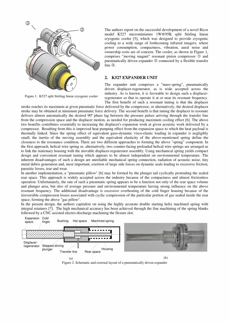
(b)
Figure 2. Schematic and external layout of a pneumatically driven expander
Expansion space
Cold finger
Stepped driving plunger
Bushing Hot space Machined spring
Transfer line Rear space Housing
Figure 1. K527 split Stirling linear cryogenic cooler
(a)
Displacer-regenerator
The self-explanatory Figure 2 shows the schematics (a) and the external layout (b) of the pneumatically driven sprung
expander. In Figure 2, the displacer-regenerator comprising a stack of stainless steel mesh disks of optimized geometry
and porosity is attached to the stepped plunger and arranged so as to slide freely inside the accurately aligned bushing
and thin-walled cold finger made of stainless steel.
The above explained machine double-helix spring is placed inside the rear space. One of the spring ends is attached to
the stationary bushing and the other to the movable plunger tail, thus forming almost friction-free design.
3. K527 LINEAR COMPRESSOR (SINGLE-PISTON VS DUAL PISTON)
As is known, the single-piston compressor is a powerful source of vibration export at driving frequency and higher-order
harmonics [8]. It is widely accepted, therefore, that dual-piston, should-be dynamically counterbalanced, compressor is
the only solution of choice for the inherently vibration sensitive cooled IR applications. The major cryogenic coolers
vendors like Thales, AIM, Carleton, DRS, Raytheon, etc. are manufacturing microminiature (below 1.5W@77K) split
Stirling cryogenic coolers comprising pneumatically driven expanders actuated by dual-piston, "moving magnet",
flexural bearing compressors, see [9,10] for example. This goes, however, on expenses of size, weight, manufacturing
costs, spoiled electromechanical performances and reliability. What is even worse, since the back-to-back compressors
forming the dual-piston one are not entirely similar (different piston-cylinder gaps and friction forces, magnet force,
driving coils resistances, etc) the residual vibration export at a driving frequency and higher-order harmonics is not really
encouraging; reaching low level of vibration export may require additional vibration isolation or, sometimes, active
vibration cancellation. With this in mind, the authors rejected the dual-piston approach and adapted the single-piston
compressor design where vibration control relies on a field proven combination of high frequency vibration isolator and
tuned dynamic absorber, as explained, for example, in [11].
The single-piston K527 linear compressor is driven by a resonant “moving magnet” actuator. This allows it to obtain a
high coefficient of performance [5] and also allows the driving coil to be separated from the working agent (Helium,
typically), thus preventing the cooler interior from being contaminated by the outgasing originated from the wire
isolation varnish, eliminating the need for flying leads and potentially leaking feedthroughs. It is also important to note
that in such an approach, sinking the intrinsic copper loses from the externally located driving coil is much improved.
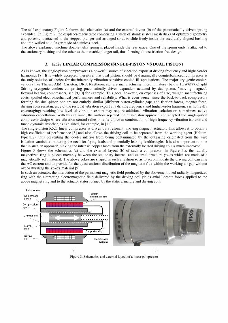
Figure 3 shows the schematics (a) and the external layout (b) of such a compressor. In Figure 3.a, the radially
magnetized ring is placed movably between the stationary internal and external armature yokes which are made of a
magnetically soft material. The above yokes are shaped in such a fashion so as to accommodate the driving coil carrying
the AC current and to provide for the quasi uniform distribution of the magnetic flux within the working air gap without
over-saturating the yoke's material [5].
In such an actuator, the interaction of the permanent magnetic field produced by the abovementioned radially magnetized
ring with the alternating electromagnetic field delivered by the driving coil yields axial Lorentz forces applied to the
above magnet ring and to the actuator stator formed by the static armature and driving coil.
(a) (b)
Figure 3. Schematics and external layout of a linear compressor
The above magnetic ring is bonded upon the magnet form, which is, in turn, rigidly attached to the compression piston,
arranged so as to slide freely inside the tightly matched cylinder liner being placed inside the internal yoke.
For the sake of compactness, a double starting helix machined spring, connecting the movable piston and stationary
housing, as is needed primarily for centering of the piston-magnet assembly, is placed inside the piston. Further, for the
sake of performance, compactness, manufacturing costs, ease of assembly and maintenance we have abandoned the most
fashionable “contactless” approache relying on flexural bearings and accurate (sometimes robotic) alignment and
assembly [10]. The piston and cylinder liners are tightly matched to 4µm radial clearance and made of M42 steel being
hardened to HRc 65 and machined to N3; no exotic surface treatment or plating were applied. As above, using precise
double starting helix machined spring allows for improved alignment, essential reduction of side and friction forces
along with eliminating metal debris generation. Additional advantage of this approach is that the piston-cylinder sleeves
may be matched more tightly as compared to the above contactless design; this results in a substantial decrease in blow-
by losses. This decision, to abandon the flexure bearing design, is based on the proven technology used currently in the
Ricor model K529N cryogenic cooler, where in the course of the accelerated life test the experimental cooler
accumulated in excess of 27,500 working hours (equivalent to 45,000 hours under standard test profile). When
investigating this experimental cooler’s failure, it appeared that electrical short in the driving coil happened due the
overheating of the inappropriately chosen varnish type [12]. The "post mortem" inspection revealed that the outer
diameter of the piston and inner diameter of the cylinder liners were still within the manufacturing tolerances and that the
working surfaces were free of abrasive scratches and wear.
Based on the theoretical analysis of [5], optimizing "moving magnet" linear actuator requires maintaining the ratio 2
R α ( R and α stand for the driving coil resistance and force/current constant, respectively) at the lowest possible level.
In an ideal case this means increasing the "copper volume" and magnetic flux in the air gap along with using low
resistive wire for making the driving coil. Not less important, in this regard, is to also provide for effective sinking of the
Joule heating originated from the driving coil.
However, in real life, the size and weight of the linear actuator are always subject to strict limitations. For this reason,
allocating more space for the driving coil leaves less space available for the yoke's material. This, in turn, leads to the
potential of spoiling the motor performance due to the local, or even global, yoke's material over-saturating and uneven
distribution of magnetic field in the air gap. Furthermore, using too much powerful permanent magnet and too tight air
gaps may also contribute to the harmful yoke's over-saturation. As a result, the design of such an actuator is always a
compromise between the space available for the driving coil and armature yokes, between the magnet power and the air
gap geometry. The optimal actuator should have uniform current-to-force transformation rate along the entire piston path
and the smallest 2R α ratio, subjected to limitations imposed on the actuator size. It is obvious that for the best
performance a thorough FEA modeling and optimization [5] of the linear actuator is needed. In practice, the rear-earth
NEODYMIUM-FERRUM-BORON materials having highest possible remanence, coercivity and energy product is the
best choice for the motor magnets. Along with these lines, the PERMENDUR alloys having highest permeability values
at very high magnetic flux densities appear to be the best choice for the motor magnets and yokes.
Eddy current control has been achieved by cutting the potential eddy current paths. Another important factor to consider
is keeping the needed working frequency of the compressor close to the resonant frequency; doing this may contribute
significantly to the overall system performance. The above
resonant condition depends primarily on the mass of the movable
assembly and the rate of the equivalent "gas spring" formed by
the portion of the working agent located "above" the piston face.
It goes without saying that varying the said mass is the easiest
way of bringing the system to the desired resonant condition and
improving the overall power consumption figure.
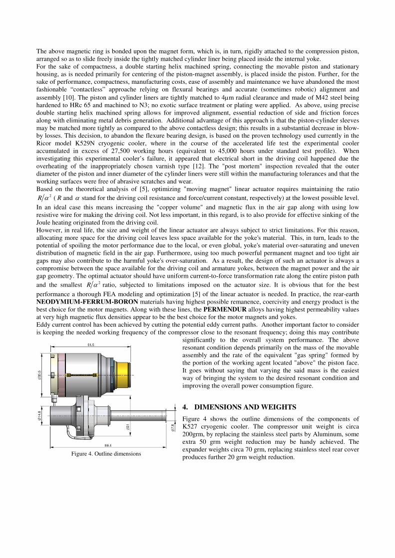
4. DIMENSIONS AND WEIGHTS
Figure 4 shows the outline dimensions of the components of
K527 cryogenic cooler. The compressor unit weight is circa
200grm, by replacing the stainless steel parts by Aluminum, some
extra 50 grm weight reduction may be handy achieved. The
expander weights circa 70 grm, replacing stainless steel rear cover
produces further 20 grm weight reduction. Figure 4. Outline dimensions
0
200
400
600
800
1000
1200
0 20 40 60 80 100 120
Ambient temperature, C
Add
ed
he
at lo
ad
, m
W
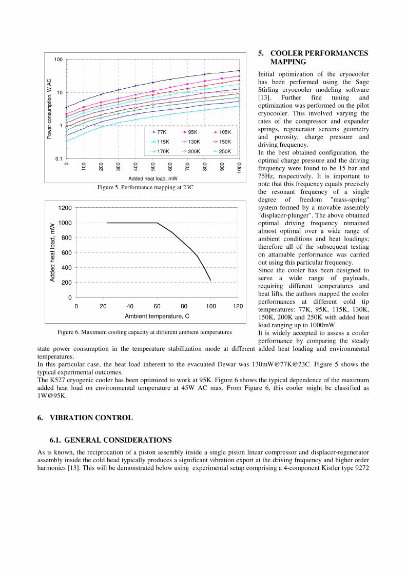
Figure 6. Maximum cooling capacity at different ambient temperatures
5. COOLER PERFORMANCES
MAPPING
Initial optimization of the cryocooler
has been performed using the Sage
Stirling cryocooler modeling software
[13]. Further fine tuning and
optimization was performed on the pilot
cryocooler. This involved varying the
rates of the compressor and expander
springs, regenerator screens geometry
and porosity, charge pressure and
driving frequency.
In the best obtained configuration, the
optimal charge pressure and the driving
frequency were found to be 15 bar and
75Hz, respectively. It is important to
note that this frequency equals precisely
the resonant frequency of a single
degree of freedom "mass-spring"
system formed by a movable assembly
"displacer-plunger". The above obtained
optimal driving frequency remained
almost optimal over a wide range of
ambient conditions and heat loadings;
therefore all of the subsequent testing
on attainable performance was carried
out using this particular frequency.
Since the cooler has been designed to
serve a wide range of payloads,
requiring different temperatures and
heat lifts, the authors mapped the cooler
performances at different cold tip
temperatures: 77K, 95K, 115K, 130K,
150K, 200K and 250K with added heat
load ranging up to 1000mW.
It is widely accepted to assess a cooler
performance by comparing the steady
state power consumption in the temperature stabilization mode at different added heat loading and environmental
temperatures.
In this particular case, the heat load inherent to the evacuated Dewar was 130mW@77K@23C. Figure 5 shows the
typical experimental outcomes.
The K527 cryogenic cooler has been optimized to work at 95K. Figure 6 shows the typical dependence of the maximum
added heat load on environmental temperature at 45W AC max. From Figure 6, this cooler might be classified as
1W@95K.
6. VIBRATION CONTROL
6.1. GENERAL CONSIDERATIONS
As is known, the reciprocation of a piston assembly inside a single piston linear compressor and displacer-regenerator
assembly inside the cold head typically produces a significant vibration export at the driving frequency and higher order
harmonics [13]. This will be demonstrated below using experimental setup comprising a 4-component Kistler type 9272
0.1
1
10
100
0
100
200
300
400
500
600
700
800
900
1000
Added heat load, mW
Pow
er
consu
mptio
n, W
AC
77K 95K 105K
115K 130K 150K
170K 200K 250K
Figure 5. Performance mapping at 23C
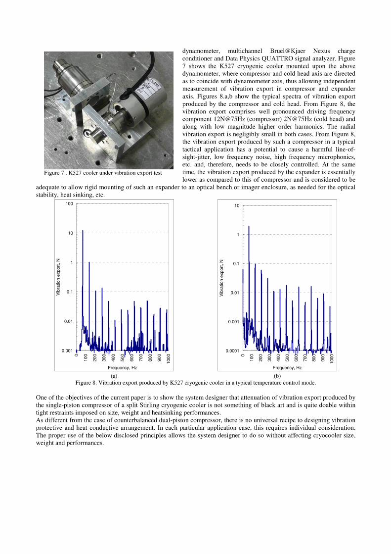
Figure 7 . K527 cooler under vibration export test
dynamometer, multichannel Bruel@Kjaer Nexus charge
conditioner and Data Physics QUATTRO signal analyzer. Figure
7 shows the K527 cryogenic cooler mounted upon the above
dynamometer, where compressor and cold head axis are directed
as to coincide with dynamometer axis, thus allowing independent
measurement of vibration export in compressor and expander
axis. Figures 8.a,b show the typical spectra of vibration export
produced by the compressor and cold head. From Figure 8, the
vibration export comprises well pronounced driving frequency
component 12N@75Hz (compressor) 2N@75Hz (cold head) and
along with low magnitude higher order harmonics. The radial
vibration export is negligibly small in both cases. From Figure 8,
the vibration export produced by such a compressor in a typical
tactical application has a potential to cause a harmful line-of-
sight-jitter, low frequency noise, high frequency microphonics,
etc. and, therefore, needs to be closely controlled. At the same
time, the vibration export produced by the expander is essentially
lower as compared to this of compressor and is considered to be
adequate to allow rigid mounting of such an expander to an optical bench or imager enclosure, as needed for the optical
stability, heat sinking, etc.
0.001
0.01
0.1
1
10
100
0
10
0
20
0
30
0
40
0
50
0
60
0
70
0
80
0
90
0
100
0
Frequency, Hz
Vib
ration
exp
ort
, N
(a)
0.0001
0.001
0.01
0.1
1
10
0
100
200
300
400
500
600
700
800
900
1000
Frequency, Hz
Vib
ration
exp
ort
, N
(b)
Figure 8. Vibration export produced by K527 cryogenic cooler in a typical temperature control mode.
One of the objectives of the current paper is to show the system designer that attenuation of vibration export produced by
the single-piston compressor of a split Stirling cryogenic cooler is not something of black art and is quite doable within
tight restraints imposed on size, weight and heatsinking performances.
As different from the case of counterbalanced dual-piston compressor, there is no universal recipe to designing vibration
protective and heat conductive arrangement. In each particular application case, this requires individual consideration.
The proper use of the below disclosed principles allows the system designer to do so without affecting cryocooler size,
weight and performances.
Heavy and rigid instrument.
To start with, let us consider the case when such a cryocooler is used inside heavy and rigid instrument, or, alternatively,
the instrument is mounted rigidly to a heavy and rigid platform. On this occasion, because of the large inertia and
stiffness, the vibration export will not be an issue at all. In this case it is recommended to clamp the compressor casing to
the system shield or the optical bench using thin (0.5 - 1mm) layer of thermo-conductive material. This is needed for
tolerance compensation, high frequency noise protection and efficient heat sinking.
Instrumentation operating in harsh environmental conditions.
In applications undergoing frequent exposure to harsh environmental extremes like random and sine vibration and no
vibration isolation is provided, the vibration exerted by the environment will be more intensive than this produced by the
compressor unit. The same mounting principle, as explained above is applicable.
Lightweight instrumentation operating in mild environmental conditions
These are hand-held, ground fixed portable and vibration isolated gyro-stabilized IR imagers. The optical performances
of the above listed equipment will be affected by the above mentioned massive vibration export, the suppression of
which may be achieved, even within a stringent weight and size budget, by combining the principles of vibration
isolation and tuned dynamic absorber, as explained in [14]. In this approach, the compressor is clamped to the imager
casing or the optical bench through a compliant vibration mount for attenuation of high frequency portion of vibration
export and a tuned dynamic absorber should be mounted coaxially on the compressor housing for suppressing the
vibration export at the driving frequency. The use of the tuned dynamic absorber becomes possible since the driving
frequency is essentially constant and may be adjusted and maintained with a very high accuracy, 0.01Hz, typically. The
heatsinking may rely on heat conductivity of compliant heat link/pipe or natural/ forced convection using the finned
radiator and micro-fan.
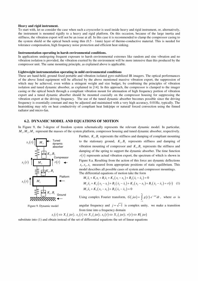
6.2. DYNAMIC MODEL AND EQUATIONS OF MOTION
In Figure 9, the 3-degree of freedom system schematically represents the relevant dynamic model. In particular,
1 2 3, ,M M M represent the masses of the system platform, compressor housing and tuned dynamic absorber, respectively.
Further, 1 1,K B represents the stiffness and damping of compliant mounting
to the stationary ground, 2 2,K B represents stiffness and damping of
vibration mounting of compressor and 3 3,K B represents the stiffness and
damping of the spring to support the dynamic absorber. The time function
( )r t represents actual vibration export, the spectrum of which is shown in
Figure 8.a. Resulting from the action of this force are dynamic deflections
1 2 3, ,x x x measured from appropriate positions of static equilibrium. This
model describes all possible cases of system and compressor mountings.
The differential equations of motion take the form
( ) ( )( ) ( ) ( ) ( ) ( )( ) ( )
1 1 1 1 1 1 2 1 2 2 1 2
2 2 2 2 1 2 2 1 3 2 3 3 2 3
3 3 3 3 2 3 3 2
0
0
M x K x B x K x x B x x
M x K x x B x x K x x B x x r t
M x K x x B x x
+ + + − + − =
+ − + − + − + − =
+ − + − =
(1)
Using complex Fourier transform, ( ) ( ) j tG j g t e dt
ωω∞
−
−∞
= ∫ , where ω is
angular frequency and 1j = − is complex unity, we make a transition
from time into a frequency domain
( ) ( ) ( ) ( ) ( ) ( ) ( ) ( )1 1 2 2 3 3; ; ; x t X j x t X j x t X j r t R jω ω ω ω⇔ ⇔ ⇔ ⇔
substitute into (1) and obtain instead of the set of differential equations the set of linear equations
1M
2M
3M
2 2,K B
1 1,K B
( )3x t
( )r t
Compressor
Platform
3 3,K B
Tuned dynamic absorber
Figure 9. Dynamic model
( )2x t
( )1x t
Ground
( ) ( )( ) ( ) ( ) ( ) ( )
( ) ( )
1 1 1 1 1 1 2 1 2 2 1 2
2 2 2 2 1 2 2 1 3 2 3 3 2 3
3 3 3 3 2 3 3 2
0
0
M X K X B X K X X B X X
M X K X X B X X K X X B X X R j
M X K X X B X X
ω
+ + + − + − =
+ − + − + − + − =
+ − + − =
(2)
The solution to (2) is trivial using, for example, the Cramer's rule. In particular, we find the complex frequency response
function (receptance) relating the dynamic response of the platform and the force applied to the compressor housing, this
is:
( ) ( )( )
( )( )( ) ( )
( ) ( ) ( )( )
2
2 2 3 3 31
1 2
1 1 2 1 2 2 2
2
2 2 2 3 2 3 2 3 3
2
3 3 3 3 3
0
0
K j B M K j BX jH j
R j M K K j B B K j B
K j B M K K j B B K j B
K j B M K j B
ω ω ωωω
ω ω ω ωω ω ω ω
ω ω ω
+ − + += =
− + + + + − +
− + − + + + + − +
− + − + +
(3)
From (3), setting 2
3 3M Kω = and
30B → , minimizes the magnitude of the above FRF at particular driving frequency
ω , i.e. the dynamic response of the base may approach zero independently on other system parameters. The above
explains the operational principle of tuned dynamic absorber, which needs to be "tuned" such as to have resonant
frequency equal exactly the driving frequency, e.g. 3 3 3
K M ωΩ = = . In practice, it is easier to adjust the driving
frequency to the above resonant frequency of tuned dynamic absorber. The complex frequency response function (3)
covers all the possible cases of systems design.
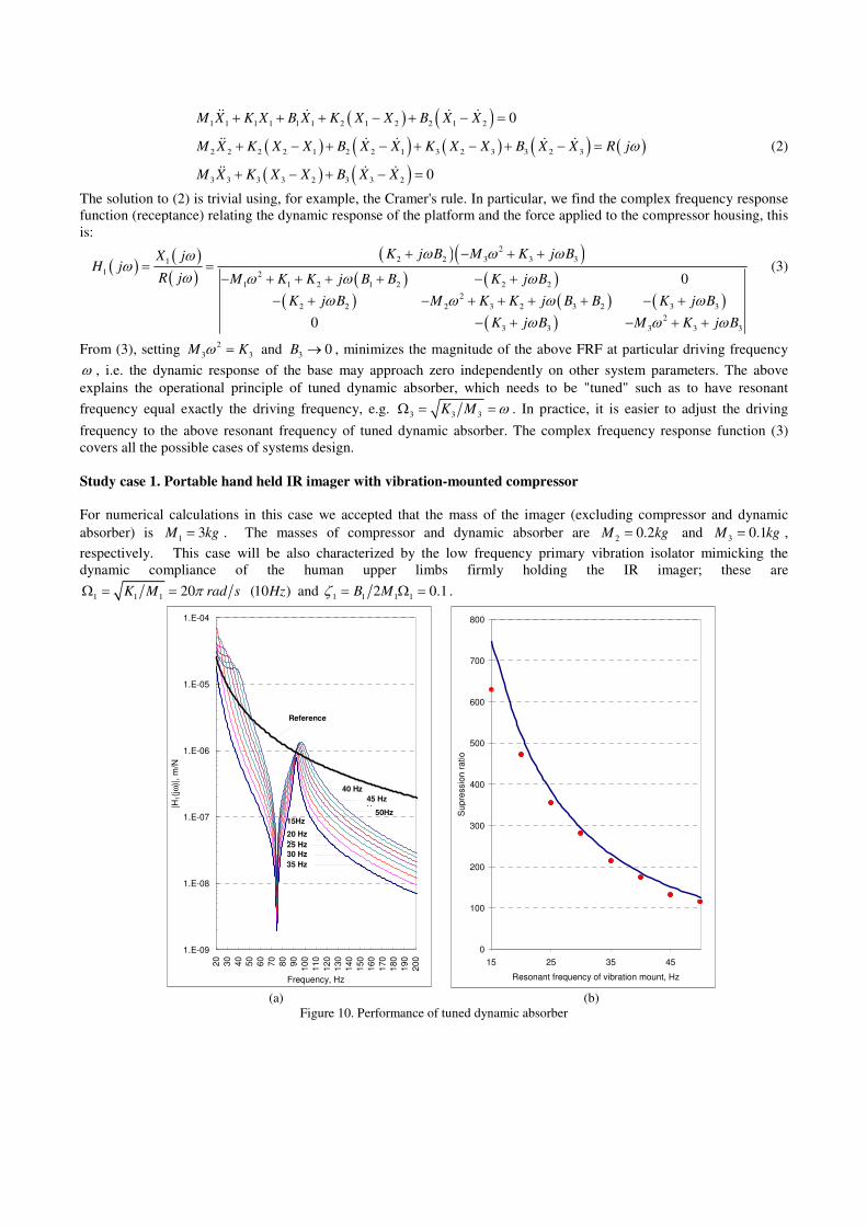
Study case 1. Portable hand held IR imager with vibration-mounted compressor
For numerical calculations in this case we accepted that the mass of the imager (excluding compressor and dynamic
absorber) is 1
3M kg= . The masses of compressor and dynamic absorber are 2
0.2M kg= and 3
0.1M kg= ,
respectively. This case will be also characterized by the low frequency primary vibration isolator mimicking the
dynamic compliance of the human upper limbs firmly holding the IR imager; these are
1 1 120 (10 )K M rad s HzπΩ = = and
1 1 1 12 0.1B Mζ = Ω = .
1.E-09
1.E-08
1.E-07
1.E-06
1.E-05
1.E-04
20
30
40
50
60
70
80
90
100
110
120
130
140
150
160
170
180
190
200
Frequency, Hz
|H1(j
ω)|
, m
/N
15Hz
50Hz
Reference
20 Hz
Hz25 Hz
Hz30 Hz
Hz35 Hz
Hz
40 Hz
Hz 45 Hz
Hz
0
100
200
300
400
500
600
700
800
15 25 35 45
Resonant frequency of vibration mount, Hz
Supre
ssio
n r
atio
(a) (b)
Figure 10. Performance of tuned dynamic absorber
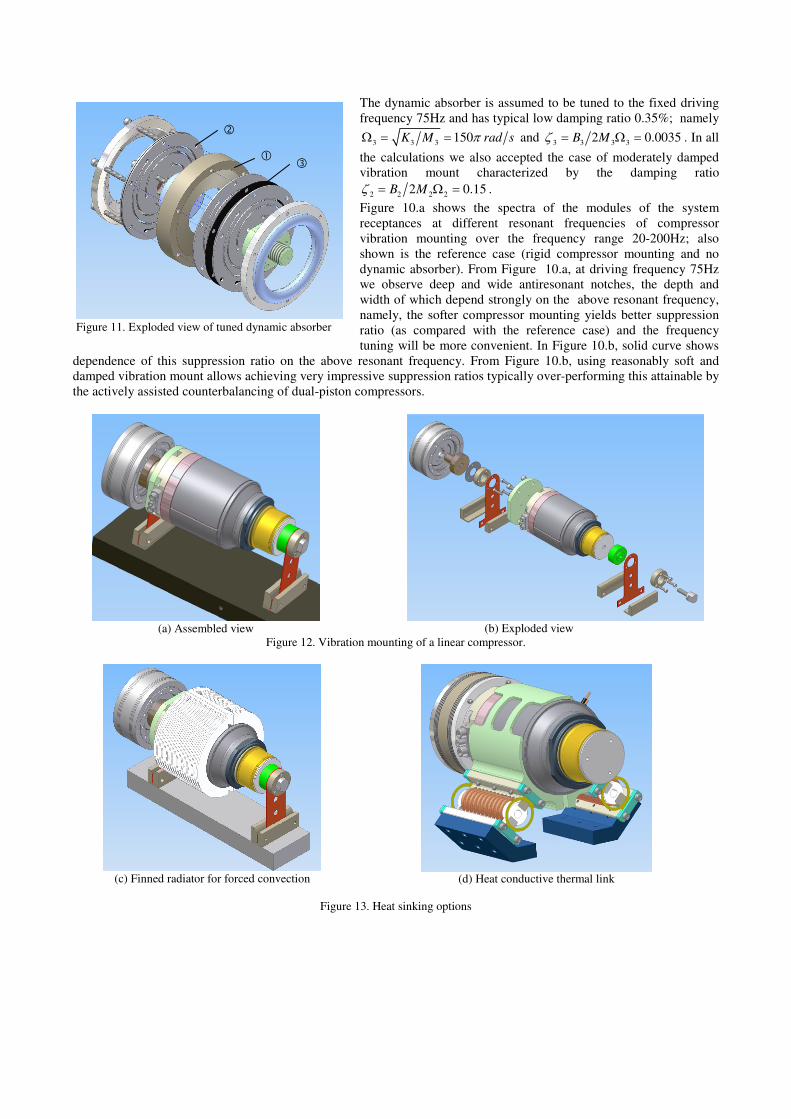
Figure 11. Exploded view of tuned dynamic absorber
The dynamic absorber is assumed to be tuned to the fixed driving
frequency 75Hz and has typical low damping ratio 0.35%; namely
3 3 3150K M rad sπΩ = = and
3 3 3 32 0.0035B Mζ = Ω = . In all
the calculations we also accepted the case of moderately damped
vibration mount characterized by the damping ratio
2 2 2 22 0.15B Mζ = Ω = .
Figure 10.a shows the spectra of the modules of the system
receptances at different resonant frequencies of compressor
vibration mounting over the frequency range 20-200Hz; also
shown is the reference case (rigid compressor mounting and no
dynamic absorber). From Figure 10.a, at driving frequency 75Hz
we observe deep and wide antiresonant notches, the depth and
width of which depend strongly on the above resonant frequency,
namely, the softer compressor mounting yields better suppression
ratio (as compared with the reference case) and the frequency
tuning will be more convenient. In Figure 10.b, solid curve shows
dependence of this suppression ratio on the above resonant frequency. From Figure 10.b, using reasonably soft and
damped vibration mount allows achieving very impressive suppression ratios typically over-performing this attainable by
the actively assisted counterbalancing of dual-piston compressors.
(a) Assembled view
(b) Exploded view
Figure 12. Vibration mounting of a linear compressor.
(c) Finned radiator for forced convection
(d) Heat conductive thermal link
Figure 13. Heat sinking options
In a practical implementation, the exploded view of which is shown in Figure 11, the tuned dynamic absorber may
comprise heavy inertial ring (made of Tungsten for compactness) which is clamped between two sets of flat flexural
bearings separated by spacers for eliminating damping effects associated with dry friction between adjacent
springs. As it was already stated above, the vibration export produced by the single piston compressor is primarily axial
and negligibly small in radial direction, the single degree of freedom vibration mount of compressor to the IR imager
will be adequate.
Figure 12.a shows one of the possible implementations of such a single degree of freedom vibration mount relying on a
set of two sets of flat metal springs supporting linear compressor. Using stacked metal flat springs provides for desired
damping in compressor's vibration mount and eliminates parasitic degrees of freedom, as needed for mechanical
stability. The tuned dynamic absorber is mounted inline with compressor. Figure 12.b shows the exploded view.
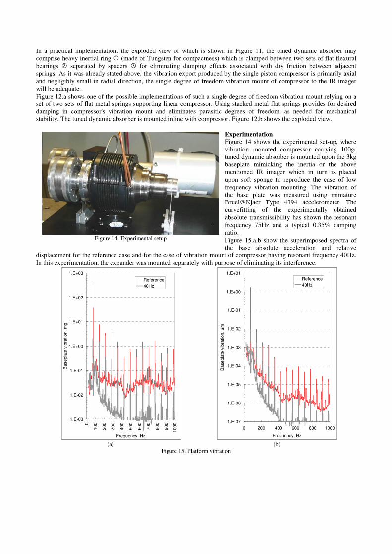
Experimentation
Figure 14 shows the experimental set-up, where
vibration mounted compressor carrying 100gr
tuned dynamic absorber is mounted upon the 3kg
baseplate mimicking the inertia or the above
mentioned IR imager which in turn is placed
upon soft sponge to reproduce the case of low
frequency vibration mounting. The vibration of
the base plate was measured using miniature
Bruel@Kjaer Type 4394 accelerometer. The
curvefitting of the experimentally obtained
absolute transmissibility has shown the resonant
frequency 75Hz and a typical 0.35% damping
ratio.
Figure 15.a,b show the superimposed spectra of
the base absolute acceleration and relative
displacement for the reference case and for the case of vibration mount of compressor having resonant frequency 40Hz.
In this experimentation, the expander was mounted separately with purpose of eliminating its interference.
1.E-03
1.E-02
1.E-01
1.E+00
1.E+01
1.E+02
1.E+03
0
100
200
300
400
500
600
700
800
900
1000
Frequency, Hz
Basep
late
vib
ratio
n,
mg
Reference
40Hz
1.E-07
1.E-06
1.E-05
1.E-04
1.E-03
1.E-02
1.E-01
1.E+00
1.E+01
0 200 400 600 800 1000
Frequency, Hz
Base
pla
te v
ibra
tion,
µm
Reference
40Hz
(a) (b)
Figure 15. Platform vibration
Figure 14. Experimental setup
From Figure 15, in the reference case the working cryocooler produces a vibration export mostly at the driving
frequency. The magnitude of the primary harmonic is 367 mg; the secondary harmonic is 46-fold smaller – 8 mg. Low
powered higher frequency content is also seen up to 1000Hz. Making use of the above explained tuned dynamic absorber
produces 175-fold vibration attenuation at driving frequency which correlates well with theoretical prediction in Figure
6. Along with these lines, we observe massive vibration attenuation over the high frequency range; this may be attributed
to the action of low frequency vibration mount.
It is important to note that this significant
vibration attenuation has been obtained using a
very light dynamic absorber, the weight of
which is only 3% relative to the entire system.
Further improvement (if needed) may be easily
achieved by incorporating a slightly heavier
tuned dynamic absorber.
The experimentation was also performed for
different vibration mounting of compressor.
The obtained suppression ratios strictly follow
prediction in Figure 10.b; the experimentally
obtained points are marked as circles.
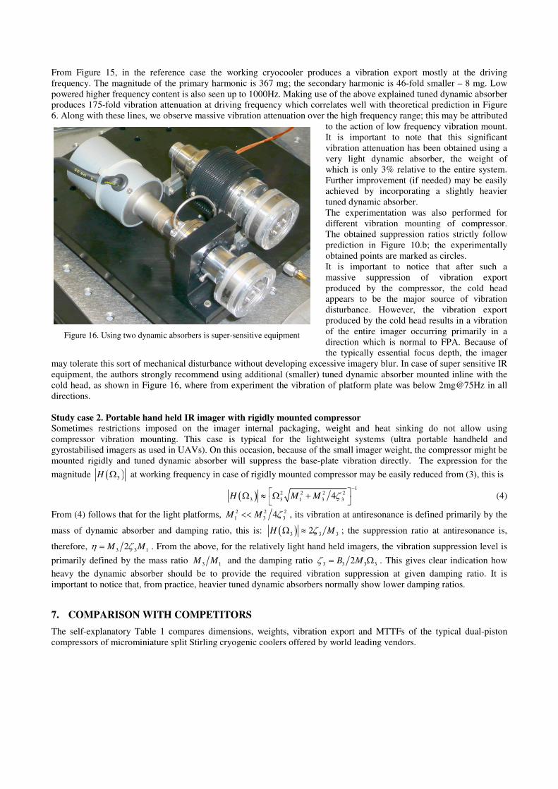
It is important to notice that after such a
massive suppression of vibration export
produced by the compressor, the cold head
appears to be the major source of vibration
disturbance. However, the vibration export
produced by the cold head results in a vibration
of the entire imager occurring primarily in a
direction which is normal to FPA. Because of
the typically essential focus depth, the imager
may tolerate this sort of mechanical disturbance without developing excessive imagery blur. In case of super sensitive IR
equipment, the authors strongly recommend using additional (smaller) tuned dynamic absorber mounted inline with the
cold head, as shown in Figure 16, where from experiment the vibration of platform plate was below 2mg@75Hz in all
directions.
Study case 2. Portable hand held IR imager with rigidly mounted compressor Sometimes restrictions imposed on the imager internal packaging, weight and heat sinking do not allow using
compressor vibration mounting. This case is typical for the lightweight systems (ultra portable handheld and
gyrostabilised imagers as used in UAVs). On this occasion, because of the small imager weight, the compressor might be
mounted rigidly and tuned dynamic absorber will suppress the base-plate vibration directly. The expression for the
magnitude ( )3H Ω at working frequency in case of rigidly mounted compressor may be easily reduced from (3), this is
( )1
2 2 2 2
3 3 1 3 34H M M ζ
− Ω ≈ Ω +
(4)
From (4) follows that for the light platforms, 2 2 2
1 3 34M M ζ<< , its vibration at antiresonance is defined primarily by the
mass of dynamic absorber and damping ratio, this is: ( )3 3 32H MζΩ ≈ ; the suppression ratio at antiresonance is,
therefore, 3 3 1
2M Mη ζ= . From the above, for the relatively light hand held imagers, the vibration suppression level is
primarily defined by the mass ratio 3 1
M M and the damping ratio 3 3 3 3
2B Mζ = Ω . This gives clear indication how
heavy the dynamic absorber should be to provide the required vibration suppression at given damping ratio. It is
important to notice that, from practice, heavier tuned dynamic absorbers normally show lower damping ratios.
7. COMPARISON WITH COMPETITORS
The self-explanatory Table 1 compares dimensions, weights, vibration export and MTTFs of the typical dual-piston
compressors of microminiature split Stirling cryogenic coolers offered by world leading vendors.
Figure 16. Using two dynamic absorbers is super-sensitive equipment
0
10
20
30
40
50
60
100
300
500
700
900
11
00
Total heat lift, mW
Pow
er
con
sum
ption, W
DC
SF070B (AIM), DC SF100A (AIM), DCSF100B (AIM), DC SL100(AIM) DCLC1040 (Carleton), DC LC1047 (Carleton), DCLC1056 (Carleton), DC LC1057 (Carleton), DCLC1062 (Carleton), DC LSF 9587 (Thales), DCLSF 9599 (Thales), DC 1W LINEAR (DRS), DC7062&196S (Raytheon), DC B602 (BEI), DCK527 (Ricor), DC UP 8497 (Thales), DC
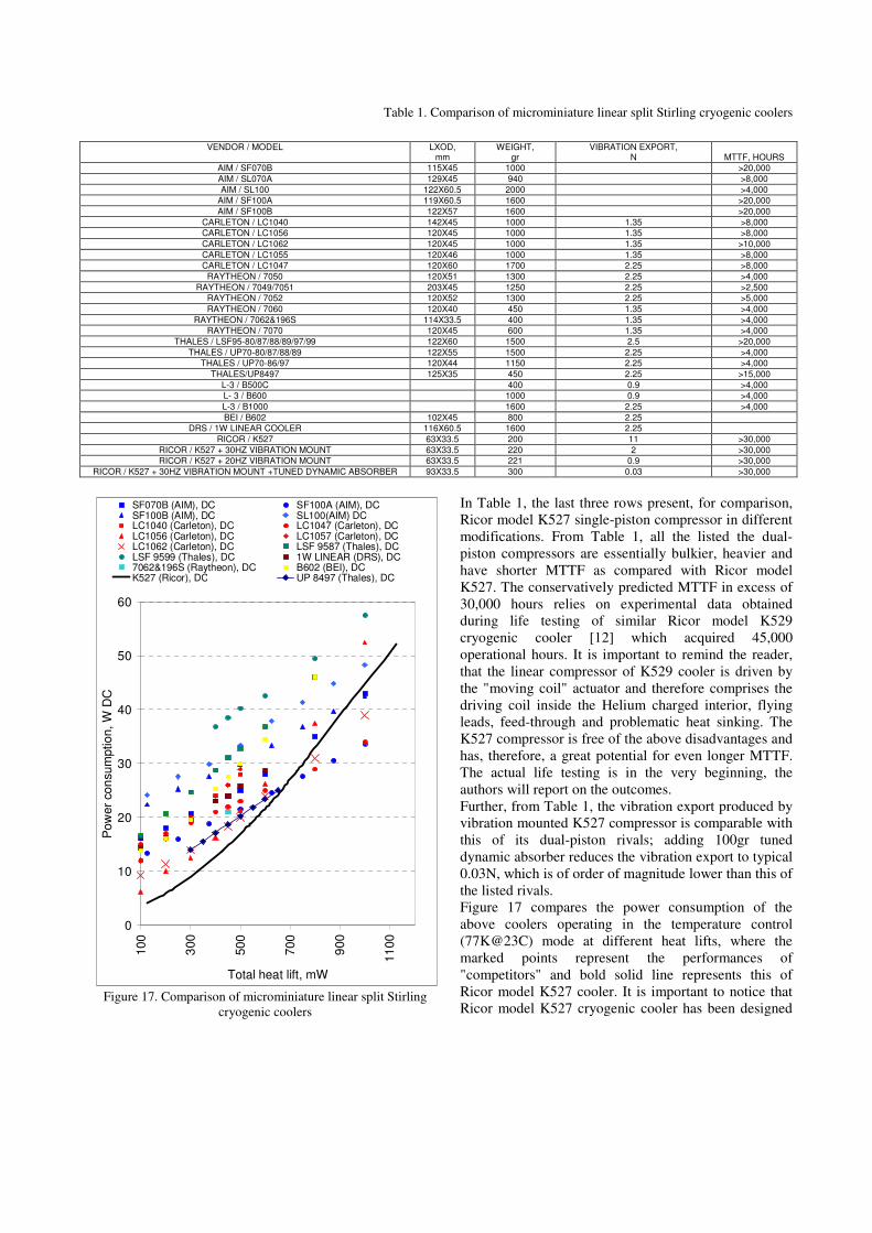
Figure 17. Comparison of microminiature linear split Stirling
cryogenic coolers
Table 1. Comparison of microminiature linear split Stirling cryogenic coolers
In Table 1, the last three rows present, for comparison,
Ricor model K527 single-piston compressor in different
modifications. From Table 1, all the listed the dual-
piston compressors are essentially bulkier, heavier and
have shorter MTTF as compared with Ricor model
K527. The conservatively predicted MTTF in excess of
30,000 hours relies on experimental data obtained
during life testing of similar Ricor model K529
cryogenic cooler [12] which acquired 45,000
operational hours. It is important to remind the reader,
that the linear compressor of K529 cooler is driven by
the "moving coil" actuator and therefore comprises the
driving coil inside the Helium charged interior, flying
leads, feed-through and problematic heat sinking. The
K527 compressor is free of the above disadvantages and
has, therefore, a great potential for even longer MTTF.
The actual life testing is in the very beginning, the
authors will report on the outcomes.
Further, from Table 1, the vibration export produced by
vibration mounted K527 compressor is comparable with
this of its dual-piston rivals; adding 100gr tuned
dynamic absorber reduces the vibration export to typical
0.03N, which is of order of magnitude lower than this of
the listed rivals.
Figure 17 compares the power consumption of the
above coolers operating in the temperature control
(77K@23C) mode at different heat lifts, where the
marked points represent the performances of
"competitors" and bold solid line represents this of
Ricor model K527 cooler. It is important to notice that
Ricor model K527 cryogenic cooler has been designed
VENDOR / MODEL
LXOD, mm
WEIGHT, gr
VIBRATION EXPORT, N MTTF, HOURS
AIM / SF070B 115X45 1000 >20,000
AIM / SL070A 129X45 940 >8,000
AIM / SL100 122X60.5 2000 >4,000
AIM / SF100A 119X60.5 1600 >20,000
AIM / SF100B 122X57 1600 >20,000
CARLETON / LC1040 142X45 1000 1.35 >8,000
CARLETON / LC1056 120X45 1000 1.35 >8,000
CARLETON / LC1062 120X45 1000 1.35 >10,000
CARLETON / LC1055 120X46 1000 1.35 >8,000
CARLETON / LC1047 120X60 1700 2.25 >8,000
RAYTHEON / 7050 120X51 1300 2.25 >4,000
RAYTHEON / 7049/7051 203X45 1250 2.25 >2,500
RAYTHEON / 7052 120X52 1300 2.25 >5,000
RAYTHEON / 7060 120X40 450 1.35 >4,000
RAYTHEON / 7062&196S 114X33.5 400 1.35 >4,000
RAYTHEON / 7070 120X45 600 1.35 >4,000
THALES / LSF95-80/87/88/89/97/99 122X60 1500 2.5 >20,000
THALES / UP70-80/87/88/89 122X55 1500 2.25 >4,000
THALES / UP70-86/97 120X44 1150 2.25 >4,000
THALES/UP8497 125X35 450 2.25 >15,000
L-3 / B500C 400 0.9 >4,000
L- 3 / B600 1000 0.9 >4,000
L-3 / B1000 1600 2.25 >4,000
BEI / B602 102X45 800 2.25
DRS / 1W LINEAR COOLER 116X60.5 1600 2.25
RICOR / K527 63X33.5 200 11 >30,000
RICOR / K527 + 30HZ VIBRATION MOUNT 63X33.5 220 2 >30,000
RICOR / K527 + 20HZ VIBRATION MOUNT 63X33.5 221 0.9 >30,000
RICOR / K527 + 30HZ VIBRATION MOUNT +TUNED DYNAMIC ABSORBER 93X33.5 300 0.03 >30,000
to show the best performances at 95K and beyond [5], meaning that it is not really optimized to work at 77K. However,
since the above-mentioned vendors are not reporting on their coolers performances at such temperatures, the authors
were forced to make comparison at 77K. Anyway, from Figure 17, the K527 cooler over-performs the others over the
range of total heat loads of 750mW.
CONCLUSIONS
The new Ricor model K527 1W@95K cryogenic cooler comprises a single-piston compressor, driven by a resonant
"moving coil" actuator, and pneumatically driven resonant expander. The decision to abandon a fashionable dual-piston
and contact-less compressor approach allowed for drastic simplifying the mechanical design. This resulted in smaller,
lighter, more power efficient and reliable cryogenic cooler, as compared with COTS available linear rivals.
The problem of vibration control was efficiently resolved by a combined use of heat conductive vibration isolator and
tuned dynamic absorber. The attainable performance of such a combination over-performs this typical for dual-piston
compressor even operated under actively assisted vibration control.
This cryogenic cooler is ideally suited for a wide range of forthcoming high-temperature electro optical instrumentation
like portable hand-held cameras, thermal weapon sights, ground fixed and vehicle mounted surveillance cameras,
gyrostablised imagers, etc.
REFERENCES
[1] Gething, M., J., “Seeking the heat in the night” Jane’s International Defense Review, 38, 42-47 (2005)
[2] Glozman, A., Harush, E., Jacobsohn, E., Klin, O., Klipstein, P., Markovitz, T., Nahum V., Saguy E., Oiknine-
Schlesinger, J., Shtrichman, I., Yassen, M., Yofis, B. and Weiss, E., “High performance InAlSb MWIR detectors
operating at 100K and beyond“, Proc. SPIE 6206, 62060M (2006)
[3] Tribolet, P., Costa, P., Fillon, P., Manissadjian, A. and Chorier, P., "Large staring arrays at Sofradir", Proc. SPIE
4820, 418 (2003)
[4] Tsao, S., Lim, H., Zhang, W. and Razeghi, M., "High operating temperature 320×256 middle-wavelength infrared
focal plane array imaging based on an InAs/InGaAs/InAlAs/InP quantum dot infrared photodetector", Appl. Phys.
Lett. 90, 201109 (2007)
[5] Veprik, A., Vilenchik, H, Riabzev, S. and Pundak, N., "Microminiature linear split Stirling cryogenic cooler for
portable infrared imagers" Proc. SPIE 6542, 65422F (2007)
[6] Walker, G., [Cryogenic coolers], Plenum Press, New York (1983)
[7] Curven, P.,W., Newell, R.,V, "Resonant piston pump", USA Patent #3,588,291 (1971)
[8] Riabzev, S., V., Veprik, A.,M. and Pundak, N., "Technical diagnostics of linear split Stirling cryocooler through the
analysis of self-induced forces", Proc. CEC/ICMC 47, 1141-1148 (2001).
[9] Mullie, J.,C., Bruins, P.,C., Benschop, T. and Meijers, M., "Development of the LSF95xx 2nd generation flexure
bearing coolers", Proc. SPIE 5783, 178 (2005)
[10] Rühlich, I., Wiedmann, T., Mai, M. and Rosenhagen C., "Flexure bearing compressor in the one-watt linear
(OWL) envelope", Proc. SPIE 6542, 65422I (2007)
[11] Veprik, A., M., Babitsky, V.,I, Pundak, N. and Riabzev S., "Vibration control of linear split Stirling cryogenic
cooler for airborne infrared application", Journal of Shock and Vibration 7(6), 363-379 (2000)
[12] Nachman, I., Veprik, A. and Pundak, N., "Life test result of Ricor K529N 1W linear cryocooler", Proc. SPIE 6542,
65422G (2007)
[13] Gedeon D., [Sage Pulse Tube Model-Class Reference Guide], Gedeon Associates (1999)
[14] Veprik, A.,M., Babitsky, V.,I., Pundak, N. and Riabzev, S., "Vibration control of linear split Stirling cryogenic
cooler for airborne infrared application", Journal of Shock and Vibration 7(6), 363-379, 2000.