Development of a Low Inductance Linear Alternator for ... · 1 American Institute of Aeronautics...
7
1 American Institute of Aeronautics and Astronautics Development of a Low Inductance Linear Alternator for Stirling Power Convertors Steven M. Geng 1 and Nicholas A. Schifer 2 NASA Glenn Research Center, Cleveland, Ohio, 44135 The free-piston Stirling power convertor is a promising technology for high-efficiency heat-to-electricity power conversion in space. Stirling power convertors typically utilize linear alternators for converting mechanical motion into electricity. The linear alternator is one of the heaviest components of modern Stirling power convertors. In addition, state-of-the-art Stirling linear alternators usually require the use of tuning capacitors or active power factor correction controllers to maximize convertor output power. The linear alternator to be discussed in this paper eliminates the need for tuning capacitors and delivers electrical power output in which current is inherently in phase with voltage. No power factor correction is needed. In addition, the linear alternator concept requires very little iron, so core loss has been virtually eliminated. This concept is a unique moving coil design where the magnetic flux path is defined by the magnets themselves. This paper presents computational predictions for two different low inductance alternator configurations. Additionally, one of the configurations was built and tested at GRC, and the experimental data is compared with the predictions. Nomenclature 3D = three-dimensional AC = alternating current ASRG = Advanced Stirling Radioisotope Generator ASC = Advanced Stirling Convertor ACU = ASC controller unit B = magnetic flux density (kGauss) B r = magnet remanence (kGauss) B-H = normal induction DC = direct current GRC = Glenn Research Center H = magnetic field strength (kOersteds) H c = coercivity (kOersteds) H ci = intrinsic coercivity (kOersteds) H k = knee location of M-H curve (kOersteds) M = magnetization (kOersteds) M-H = intrinsic induction RHU = radioisotope heater unit RPS = Radioisotope Power System SOA = state-of-the-art SCTD = Stirling Cycle Technology Development I. Introduction TIRLING Radioisotope Power Systems are being developed by NASA’s RPS Program in collaboration with the U.S. Department of Energy. RPSs could provide power to future space science missions where robotic spacecraft will orbit, flyby, land, or rove at targets of interest. The Stirling Cycle Technology Development Project (SCTD) is funded by the RPS Program to develop Stirling-based subsystems, including convertors and controller 1 Engineer, Thermal Energy Conversion Branch, 21000 Brookpark Road, M/S 301-2, and AIAA Senior Member. 2 Engineer, Thermal Energy Conversion Branch, 21000 Brookpark Road, M/S 301-2. S https://ntrs.nasa.gov/search.jsp?R=20170006537 2018-11-23T03:25:28+00:00Z
Transcript of Development of a Low Inductance Linear Alternator for ... · 1 American Institute of Aeronautics...
1 American Institute of Aeronautics and Astronautics
Development of a Low Inductance Linear Alternator for Stirling Power Convertors
Steven M. Geng1 and Nicholas A. Schifer2 NASA Glenn Research Center, Cleveland, Ohio, 44135
The free-piston Stirling power convertor is a promising technology for high-efficiency heat-to-electricity power conversion in space. Stirling power convertors typically utilize linear alternators for converting mechanical motion into electricity. The linear alternator is one of the heaviest components of modern Stirling power convertors. In addition, state-of-the-art Stirling linear alternators usually require the use of tuning capacitors or active power factor correction controllers to maximize convertor output power. The linear alternator to be discussed in this paper eliminates the need for tuning capacitors and delivers electrical power output in which current is inherently in phase with voltage. No power factor correction is needed. In addition, the linear alternator concept requires very little iron, so core loss has been virtually eliminated. This concept is a unique moving coil design where the magnetic flux path is defined by the magnets themselves. This paper presents computational predictions for two different low inductance alternator configurations. Additionally, one of the configurations was built and tested at GRC, and the experimental data is compared with the predictions.
Nomenclature 3D = three-dimensional AC = alternating current ASRG = Advanced Stirling Radioisotope Generator ASC = Advanced Stirling Convertor ACU = ASC controller unit B = magnetic flux density (kGauss) Br = magnet remanence (kGauss) B-H = normal induction DC = direct current GRC = Glenn Research Center H = magnetic field strength (kOersteds) Hc = coercivity (kOersteds) Hci = intrinsic coercivity (kOersteds) Hk = knee location of M-H curve (kOersteds) M = magnetization (kOersteds) M-H = intrinsic induction RHU = radioisotope heater unit RPS = Radioisotope Power System SOA = state-of-the-art SCTD = Stirling Cycle Technology Development
I. Introduction TIRLING Radioisotope Power Systems are being developed by NASA’s RPS Program in collaboration with the U.S. Department of Energy. RPSs could provide power to future space science missions where robotic
spacecraft will orbit, flyby, land, or rove at targets of interest. The Stirling Cycle Technology Development Project (SCTD) is funded by the RPS Program to develop Stirling-based subsystems, including convertors and controller
1 Engineer, Thermal Energy Conversion Branch, 21000 Brookpark Road, M/S 301-2, and AIAA Senior Member. 2 Engineer, Thermal Energy Conversion Branch, 21000 Brookpark Road, M/S 301-2.
S
https://ntrs.nasa.gov/search.jsp?R=20170006537 2018-11-23T03:25:28+00:00Z
2 American Institute of Aeronautics and Astronautics
maturation efforts that have resulted in high fidelity hardware like the ASRG, ASC, and ACU.1,2 The SCTD Project also performs research to develop less mature technologies with a wide variety of objectives, including increasing temperature capability to enable new environments, improving system reliability or fault tolerance, reducing mass or size, and developing advanced concepts that are mission enabling.3 The development of the new linear alternator concepts discussed in this paper is focused on improving system reliability and reducing mass. The design and modeling were done internally at NASA GRC.
The linear alternator is one of the heaviest components of free-piston Stirling power convertors. Modern Stirling linear alternators require the use of tuning capacitors or active power factor correction controllers to maximize convertor output power. The alternator to be discussed herein eliminates the need for heavy tuning capacitors and delivers electrical power output in which current is inherently in phase with voltage. No power factor correction is needed. The alternator concept does include some iron laminations, but only inside the coil windings. Minimizing the use of iron has a positive impact on the alternator mass. The innovation developed is a unique, moving coil linear alternator that makes use of either a dual-Halbach array of magnets or other magnet arrangement, and requires no magnetic conducting structures other than the magnets themselves. The dual-Halbach array of permanent magnets generates a large magnetic field, and guides the flow of that magnetic field around the magnetic circuit. Dual-Halbach arrays have been previously used in rotary, axial flux permanent magnet motors with tremendous success.4 The power density of dual-Halbach array rotary motors is approximately three times higher than previous SOA motor technologies. A similar power density boost is possible in the linear alternator concepts proposed here. In both concepts, iron can be positioned inside the coil windings to bridge the air gap between the adjacent magnet poles. By adding a small amount of iron inside the core, it has been demonstrated that the output power increases dramatically, with little to no effect on power factor.
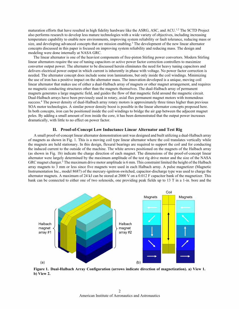
II. Proof-of-Concept Low Inductance Linear Alternator and Test Rig A small proof-of-concept linear alternator demonstration unit was designed and built utilizing a dual-Halbach array
of magnets as shown in Fig. 1. This is a moving coil type linear alternator where the coil translates vertically while the magnets are held stationary. In this design, flexural bearings are required to support the coil and for conducting the induced current to the outside of the machine. The white arrows positioned on the magnets of the Halbach array (as shown in Fig. 1b) indicate the charge direction of each magnet. The dimensions of the proof-of-concept linear alternator were largely determined by the maximum amplitude of the test rig drive motor and the size of the NASA GRC magnet charger.5 The maximum drive motor amplitude is 6 mm. This constraint limited the height of the Halbach array magnets to 3 mm or less since five magnets were used in each Halbach array. A pulse magnetizer (Magnetic Instrumentation Inc., model 8687) of the mercury-ignitron-switched, capacitor-discharge type was used to charge the alternator magnets. A maximum of 24 kJ can be stored at 2000 V on a 0.012 F capacitor bank of the magnetizer. This bank can be connected to either one of two solenoids, one providing peak fields up to 13 T in a 1-in. bore and the
Figure 1. Dual-Halbach Array Configuration (arrows indicate direction of magnetization). a) View 1. b) View 2.
3 American Institute of Aeronautics and Astronautics
other up to 10 T in a 1.75-in bore. The 1.75-in bore solenoid was selected to charge the largest magnets that this equipment could handle.
Sintered neodymium-iron-boron magnets were used in the demonstration hardware. These magnets were selected because several existing large blocks of material were available in storage. With these types of magnets, the magnet material is formed with a preferred magnetization direction. After the magnet block is made, it can only be magnetized in one direction. The magnets used in the demonstration model were cut from the parent block material with consideration given to this characteristic.
A transient model of the linear alternator demonstration unit was developed using ANSYS’s Maxwell 3D finite element method software.6 The model was created to take advantage of symmetry, thereby reducing computation time. The key alternator components included in the model are the coil (220 turns of 26 gauge round magnet wire), the coil core (air or Supermendur), and ten magnets (UGIMAG 40HC2). Because the alternator is symmetric to the half section, only half the coil and coil core and five of the ten magnets were needed in the model to represent the entire alternator. This model was first used to design the low-power demonstration alternator based on the given constraints due to the available magnet material and drive motor. The resulting alternator design provided the basic dimensions of the critical alternator components, which enabled the design of the physical components and test rig. This model was also later validated with the test data.
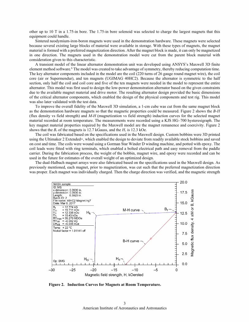
To improve the overall fidelity of the Maxwell 3D simulation, a 1-cm cube was cut from the same magnet block as the demonstration hardware magnets so that the magnetic properties could be measured. Figure 2 shows the B-H (flux density vs field strength) and M-H (magnetization vs field strength) induction curves for the selected magnet material recorded at room temperature. The measurements were recorded using a KJS HG–700 hysteresigraph. The key magnet material properties required by the Maxwell model are the magnet remanence and coercivity. Figure 2 shows that the Br of the magnets is 12.7 kGauss, and the Hc is 12.3 kOe.
The coil was fabricated based on the specifications used in the Maxwell design. Custom bobbins were 3D printed using the Ultimaker 2 Extended+, which enabled the design to deviate from readily available stock bobbins and saved on cost and time. The coils were wound using a Gorman Star Winder D winding machine, and potted with epoxy. The coil leads were fitted with ring terminals, which enabled a bolted electrical path and easy removal from the paddle carrier. During the fabrication process, the weight of the bobbin, magnet wire, and epoxy were recorded and can be used in the future for estimates of the overall weight of an optimized design.
The dual-Halbach magnet arrays were also fabricated based on the specifications used in the Maxwell design. As previously mentioned, each magnet, prior to magnetization, was cut such that the preferred magnetization direction was proper. Each magnet was individually charged. Then the charge direction was verified, and the magnetic strength
Figure 2. Induction Curves for Magnets at Room Temperature.
4 American Institute of Aeronautics and Astronautics
was measured with a Magnetic Instrumentation model HCP precision Helmholtz coil (coupled with a model 2130 fluxmeter). The arrays were assembled one magnet at a time using a custom clamping fixture and epoxied together. With both arrays fully assembled, the magnetic field strength generated between the arrays was measured using a slotted plate of known thickness to create a gap and placing the probe of a FW Bell model 6010 Gaussmeter between the arrays. This measured value was then compared against the model results, and found to be in good agreement.
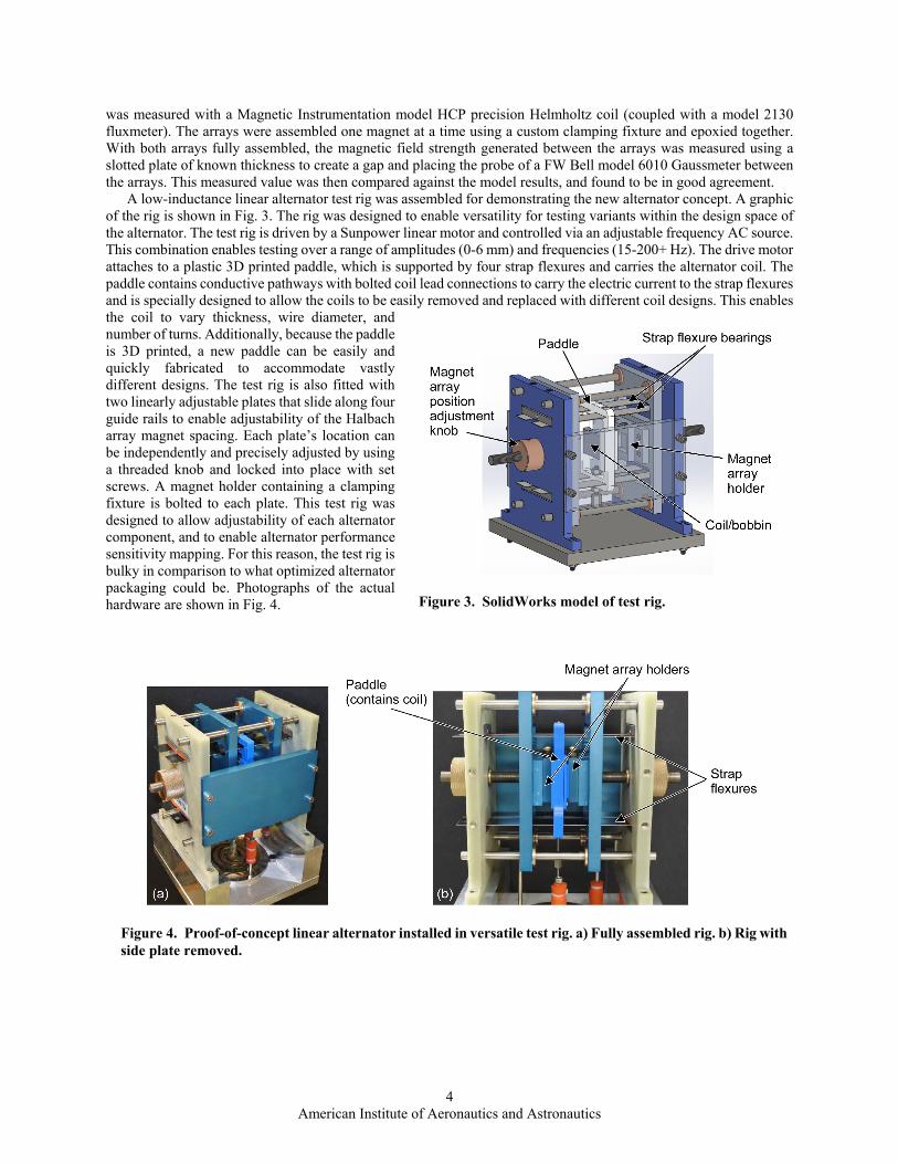
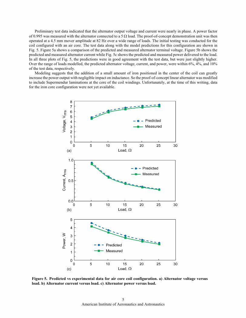
A low-inductance linear alternator test rig was assembled for demonstrating the new alternator concept. A graphic of the rig is shown in Fig. 3. The rig was designed to enable versatility for testing variants within the design space of the alternator. The test rig is driven by a Sunpower linear motor and controlled via an adjustable frequency AC source. This combination enables testing over a range of amplitudes (0-6 mm) and frequencies (15-200+ Hz). The drive motor attaches to a plastic 3D printed paddle, which is supported by four strap flexures and carries the alternator coil. The paddle contains conductive pathways with bolted coil lead connections to carry the electric current to the strap flexures and is specially designed to allow the coils to be easily removed and replaced with different coil designs. This enables the coil to vary thickness, wire diameter, and number of turns. Additionally, because the paddle is 3D printed, a new paddle can be easily and quickly fabricated to accommodate vastly different designs. The test rig is also fitted with two linearly adjustable plates that slide along four guide rails to enable adjustability of the Halbach array magnet spacing. Each plate’s location can be independently and precisely adjusted by using a threaded knob and locked into place with set screws. A magnet holder containing a clamping fixture is bolted to each plate. This test rig was designed to allow adjustability of each alternator component, and to enable alternator performance sensitivity mapping. For this reason, the test rig is bulky in comparison to what optimized alternator packaging could be. Photographs of the actual hardware are shown in Fig. 4.
Figure 3. SolidWorks model of test rig.
Figure 4. Proof-of-concept linear alternator installed in versatile test rig. a) Fully assembled rig. b) Rig with side plate removed.
5 American Institute of Aeronautics and Astronautics
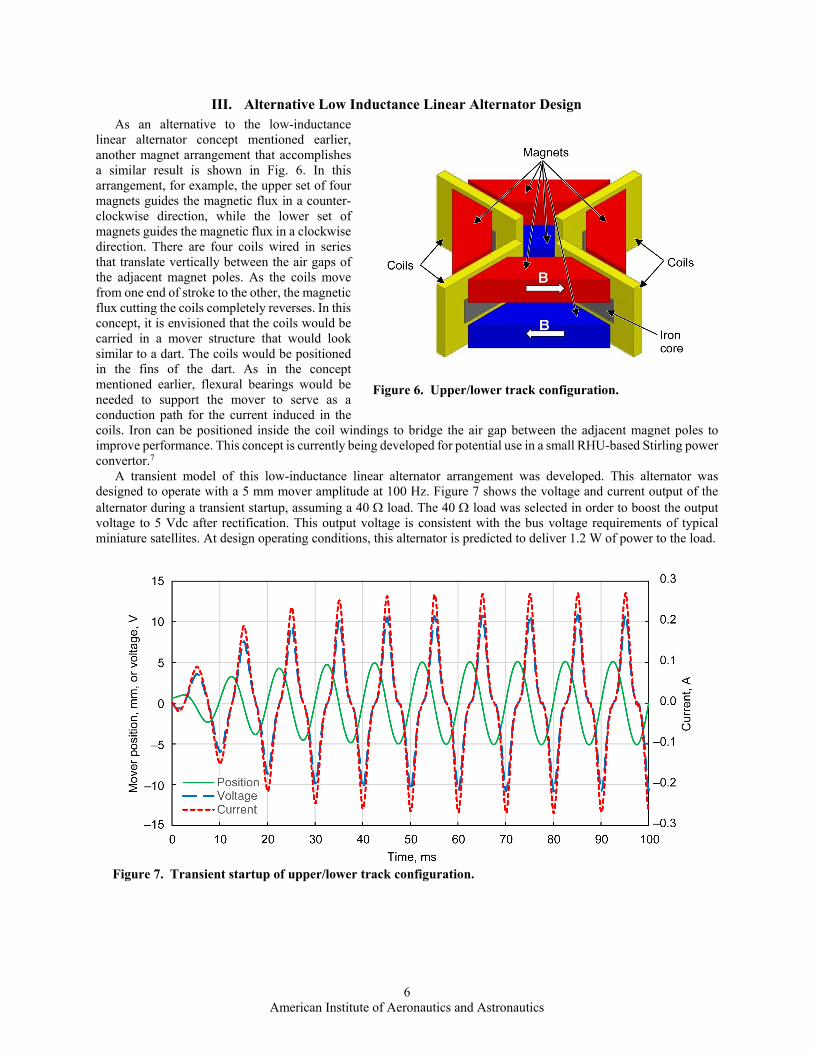
Preliminary test data indicated that the alternator output voltage and current were nearly in phase. A power factor of 0.995 was measured with the alternator connected to a 5 load. The proof-of-concept demonstration unit was then operated at a 4.5 mm mover amplitude at 82 Hz over a wide range of loads. The initial testing was conducted for the coil configured with an air core. The test data along with the model predictions for this configuration are shown in Fig. 5. Figure 5a shows a comparison of the predicted and measured alternator terminal voltage. Figure 5b shows the predicted and measured alternator current while Fig. 5c shows the predicted and measured power delivered to the load. In all three plots of Fig. 5, the predictions were in good agreement with the test data, but were just slightly higher. Over the range of loads modelled, the predicted alternator voltage, current, and power, were within 6%, 4%, and 10% of the test data, respectively.
Modeling suggests that the addition of a small amount of iron positioned in the center of the coil can greatly increase the power output with negligible impact on inductance. So the proof-of-concept linear alternator was modified to include Supermendur laminations at the core of the coil windings. Unfortunately, at the time of this writing, data for the iron core configuration were not yet available.
Figure 5. Predicted vs experimental data for air core coil configuration. a) Alternator voltage versus load. b) Alternator current versus load. c) Alternator power versus load.
6 American Institute of Aeronautics and Astronautics
III. Alternative Low Inductance Linear Alternator Design As an alternative to the low-inductance
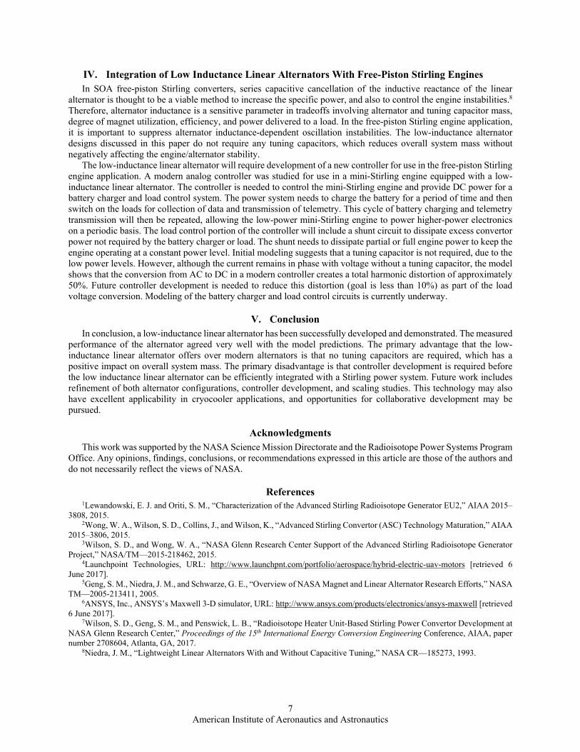
linear alternator concept mentioned earlier, another magnet arrangement that accomplishes a similar result is shown in Fig. 6. In this arrangement, for example, the upper set of four magnets guides the magnetic flux in a counter-clockwise direction, while the lower set of magnets guides the magnetic flux in a clockwise direction. There are four coils wired in series that translate vertically between the air gaps of the adjacent magnet poles. As the coils move from one end of stroke to the other, the magnetic flux cutting the coils completely reverses. In this concept, it is envisioned that the coils would be carried in a mover structure that would look similar to a dart. The coils would be positioned in the fins of the dart. As in the concept mentioned earlier, flexural bearings would be needed to support the mover to serve as a conduction path for the current induced in the coils. Iron can be positioned inside the coil windings to bridge the air gap between the adjacent magnet poles to improve performance. This concept is currently being developed for potential use in a small RHU-based Stirling power convertor.7
A transient model of this low-inductance linear alternator arrangement was developed. This alternator was designed to operate with a 5 mm mover amplitude at 100 Hz. Figure 7 shows the voltage and current output of the alternator during a transient startup, assuming a 40 load. The 40 load was selected in order to boost the output voltage to 5 Vdc after rectification. This output voltage is consistent with the bus voltage requirements of typical miniature satellites. At design operating conditions, this alternator is predicted to deliver 1.2 W of power to the load.
Figure 6. Upper/lower track configuration.
Figure 7. Transient startup of upper/lower track configuration.
7 American Institute of Aeronautics and Astronautics
IV. Integration of Low Inductance Linear Alternators With Free-Piston Stirling Engines In SOA free-piston Stirling converters, series capacitive cancellation of the inductive reactance of the linear
alternator is thought to be a viable method to increase the specific power, and also to control the engine instabilities.8 Therefore, alternator inductance is a sensitive parameter in tradeoffs involving alternator and tuning capacitor mass, degree of magnet utilization, efficiency, and power delivered to a load. In the free-piston Stirling engine application, it is important to suppress alternator inductance-dependent oscillation instabilities. The low-inductance alternator designs discussed in this paper do not require any tuning capacitors, which reduces overall system mass without negatively affecting the engine/alternator stability.
The low-inductance linear alternator will require development of a new controller for use in the free-piston Stirling engine application. A modern analog controller was studied for use in a mini-Stirling engine equipped with a low-inductance linear alternator. The controller is needed to control the mini-Stirling engine and provide DC power for a battery charger and load control system. The power system needs to charge the battery for a period of time and then switch on the loads for collection of data and transmission of telemetry. This cycle of battery charging and telemetry transmission will then be repeated, allowing the low-power mini-Stirling engine to power higher-power electronics on a periodic basis. The load control portion of the controller will include a shunt circuit to dissipate excess convertor power not required by the battery charger or load. The shunt needs to dissipate partial or full engine power to keep the engine operating at a constant power level. Initial modeling suggests that a tuning capacitor is not required, due to the low power levels. However, although the current remains in phase with voltage without a tuning capacitor, the model shows that the conversion from AC to DC in a modern controller creates a total harmonic distortion of approximately 50%. Future controller development is needed to reduce this distortion (goal is less than 10%) as part of the load voltage conversion. Modeling of the battery charger and load control circuits is currently underway.
V. Conclusion In conclusion, a low-inductance linear alternator has been successfully developed and demonstrated. The measured
performance of the alternator agreed very well with the model predictions. The primary advantage that the low-inductance linear alternator offers over modern alternators is that no tuning capacitors are required, which has a positive impact on overall system mass. The primary disadvantage is that controller development is required before the low inductance linear alternator can be efficiently integrated with a Stirling power system. Future work includes refinement of both alternator configurations, controller development, and scaling studies. This technology may also have excellent applicability in cryocooler applications, and opportunities for collaborative development may be pursued.
Acknowledgments This work was supported by the NASA Science Mission Directorate and the Radioisotope Power Systems Program
Office. Any opinions, findings, conclusions, or recommendations expressed in this article are those of the authors and do not necessarily reflect the views of NASA.
References 1Lewandowski, E. J. and Oriti, S. M., “Characterization of the Advanced Stirling Radioisotope Generator EU2,” AIAA 2015–
3808, 2015. 2Wong, W. A., Wilson, S. D., Collins, J., and Wilson, K., “Advanced Stirling Convertor (ASC) Technology Maturation,” AIAA
2015–3806, 2015. 3Wilson, S. D., and Wong, W. A., “NASA Glenn Research Center Support of the Advanced Stirling Radioisotope Generator
Project,” NASA/TM—2015-218462, 2015. 4Launchpoint Technologies, URL: http://www.launchpnt.com/portfolio/aerospace/hybrid-electric-uav-motors [retrieved 6
June 2017]. 5Geng, S. M., Niedra, J. M., and Schwarze, G. E., “Overview of NASA Magnet and Linear Alternator Research Efforts,” NASA
TM—2005-213411, 2005. 6ANSYS, Inc., ANSYS’s Maxwell 3-D simulator, URL: http://www.ansys.com/products/electronics/ansys-maxwell [retrieved
6 June 2017]. 7Wilson, S. D., Geng, S. M., and Penswick, L. B., “Radioisotope Heater Unit-Based Stirling Power Convertor Development at
NASA Glenn Research Center,” Proceedings of the 15th International Energy Conversion Engineering Conference, AIAA, paper number 2708604, Atlanta, GA, 2017.
8Niedra, J. M., “Lightweight Linear Alternators With and Without Capacitive Tuning,” NASA CR—185273, 1993.