Compact Linear Split Stirling Cryogenic Cooler for High ...€¦ · Their known advantages are...
12
High Temperature Infrared Imagers A. Veprik, S. Zehtzer, N. Pundak, S. Riabzev * ¶Ricor, Cryogenic and Vacuum Systems, ¶En Harod, 18960, Israel *EADS Astrium LTD ¶Stevenage, SG1 2AS, UK ABSTRACT Novel high-definition night vision imagers are being enabled by new high-temperature infra- red detectors that operate at elevated temperatures ranging from 95K to 200K; these have perfor- mance indices comparable with those of their 77K predecessors. Recent technological progress towards industrial implementation of such detectors has moti- vated the development of microminiature split Stirling linear cryocoolers. These coolers have great potential to replace the traditionally used rotary integral Stirling coolers. Their known advantages are superior flexibility in system packaging, constant and high drive frequency, lower wideband vibration export, unsurpassed reliability, and aural stealth. Unfortunately, off-the-shelf available tactical linear coolers relying on flexural-bearing, contactless, dual-piston compressors are thus far oversized, overweight, overpowered, and overpriced as compared to their rotary competitors. The authors report on the successful development of the smallest in the range Ricor model K527 microminiature 1W at 95K split Stirling linear cryogenic cooler. This cooler relies on a single piston externally counterbalanced linear compressor, and was designed to provide cryogenic cooling to a wide range of forthcoming infrared imagers, particularly those where power consump- tion, compactness, vibration, aural noise, and ownership costs are of concern. INTRODUCTION Infrared (IR) imagers play a vital role in the modern tactics of carrying out surveillance, recon- naissance, and targeting. By converting the thermal battlefield into dynamic visual imagery, such equipment dramatically enhances the observation and command control capabilities of the leaders of combat infantry and Special Forces. In spite of the recent advances and widespread use of uncooled infrared detectors, it is still generally accepted that the “best technology for true IR heat detection is the cooled detector” [1]. Cold detectors are outperforming their uncooled competitors in terms of working ranges, resolu- tion, and ability to detect/track fast moving objects in dynamic infrared scenes. The superior perfor- mance of such imagers is achieved by using novel optronic technologies along with maintaining their IR focal plane arrays (FPA) at cryogenic temperatures (77K, typically) using microminiature Stirling closed-cycle cryogenic coolers. Compact Linear Split Stirling Cryogenic Cooler for 121
Transcript of Compact Linear Split Stirling Cryogenic Cooler for High ...€¦ · Their known advantages are...
High Temperature Infrared Imagers
A. Veprik, S. Zehtzer, N. Pundak, S. Riabzev*
¶Ricor, Cryogenic and Vacuum Systems,
¶En Harod, 18960, Israel
*EADS Astrium LTD
¶Stevenage, SG1 2AS, UK
ABSTRACT
Novel high-definition night vision imagers are being enabled by new high-temperature infra-
red detectors that operate at elevated temperatures ranging from 95K to 200K; these have perfor-
mance indices comparable with those of their 77K predecessors.
Recent technological progress towards industrial implementation of such detectors has moti-
vated the development of microminiature split Stirling linear cryocoolers. These coolers have great
potential to replace the traditionally used rotary integral Stirling coolers. Their known advantages
are superior flexibility in system packaging, constant and high drive frequency, lower wideband
vibration export, unsurpassed reliability, and aural stealth. Unfortunately, off-the-shelf available
tactical linear coolers relying on flexural-bearing, contactless, dual-piston compressors are thus far
oversized, overweight, overpowered, and overpriced as compared to their rotary competitors.
The authors report on the successful development of the smallest in the range Ricor model
K527 microminiature 1W at 95K split Stirling linear cryogenic cooler. This cooler relies on a
single piston externally counterbalanced linear compressor, and was designed to provide cryogenic
cooling to a wide range of forthcoming infrared imagers, particularly those where power consump-
tion, compactness, vibration, aural noise, and ownership costs are of concern.
INTRODUCTION
Infrared (IR) imagers play a vital role in the modern tactics of carrying out surveillance, recon-
naissance, and targeting. By converting the thermal battlefield into dynamic visual imagery, such
equipment dramatically enhances the observation and command control capabilities of the leaders
of combat infantry and Special Forces.
In spite of the recent advances and widespread use of uncooled infrared detectors, it is still
generally accepted that the “best technology for true IR heat detection is the cooled detector” [1].
Cold detectors are outperforming their uncooled competitors in terms of working ranges, resolu-
tion, and ability to detect/track fast moving objects in dynamic infrared scenes. The superior perfor-
mance of such imagers is achieved by using novel optronic technologies along with maintaining
their IR focal plane arrays (FPA) at cryogenic temperatures (77K, typically) using microminiature
Stirling closed-cycle cryogenic coolers.
Compact Linear Split Stirling Cryogenic Cooler
for
121

Over the past few years, industrial progress has led to the development of a new InAlSb diode
technology relying on Antimonide Based Compound Semiconductors (ABCS), offering lower dark
currents or higher operating temperatures (being in the 100¶K region) [2]. The SWIR MCT technol-
ogy [3] offers the possibility of operating a FPA at even higher temperatures, in excess of 200 K.
The authors of [4] report on a 320×256 middle-wavelength infrared focal plane array based on InAs
quantum-dot/InGaAs quantum-well/InAlAs barrier detector operating at temperatures of up to 200K.
The direct benefits of using such high temperature IR FPAs are the lowering of the cooling
constraints, thus resulting in a simplified system design, using smaller and more cost effective, long
life cryocoolers inherently consuming less electrical power and showing faster cooldown times.
Traditionally, integral rotary cryocoolers have been used for maintaining cooled IR FPAs at
their optimal cryogenic temperatures. As compared to their military off-the-shelf linear competi-
tors, they are lighter, more compact, and normally have better electromechanical performance indi-
ces. However, their inherent drawbacks, such as high wideband vibration export and limited lifespan
have spurred the development of the microminiature linearly driven Stirling cryogenic coolers. An
additional advantage of linear cryocoolers, as compared with their rotary rivals, should be that, at
least in theory, they might operate at elevated driving frequencies without compromising their overall
life span.
These novel, long-life, acoustically, and dynamically quiet cryogenic coolers, while being su-
perior in many respects, need to be comparable to the above rotary cryocoolers in terms of bulk,
power consumption, and ownership costs. Unfortunately, such coolers are still not off-the-shelf
available; the existing linear tactical coolers that rely on flexural bearings and contactless dual-
piston compressors are oversized, overweight, overpriced and power-thirsty, thus making them
inadequate for the above purposes.
The authors report on the successful development of a novel Ricor model K527 microminia-
ture 1W at 95¶K split Stirling linear cryogenic cooler [5,6], which was designed to provide cryo-
genic cooling to a wide range of forthcoming infrared imagers where power consumption, com-
pactness, vibration, aural noise, and ownership costs are of concern. In the design of the Ricor
model K527 cryogenic cooler, the authors abandoned the more traditional contactless flexural bear-
ing dual-piston compressor approach in favor of an externally counterbalanced, vibration isolated
single-piston compressor. This design was made possible by eliminating the weight of one moving
assembly and using novel technology and tribological wear-resistant materials for manufacturing
the rubbing, tightly matched piston/cylinder liners. This has enabled a low vibration, high perfor-
mance, long life and compact cryocooler for use in portable handheld, ground based and gyrostabilized
IR imagers.
THERMODYNAMIC DESIGN OF CRYOGENIC COOLER
Numerical Modeling and Optimization
Computer modeling and optimization of the geometric/functional parameters was completed
during the initial phase of the K527 Stirling cryocooler design. The baseline configuration was
chosen with respect to its potential for providing high efficiency, compactness, robustness and low
cost. The detailed cooler mechanism architecture was modeled as described below, including the
temperature dependency of the displacer gap along its length.
Goal of Optimization
The optimization goal was to minimize the PV power at the cooler piston face required to
deliver a nominal heat lift of 300mW at 95K at 28°C, and a maximum heat lift of 750mW at 95K at
28°C, these being consistent with a need for the minimum redundancy and reasonably fast cool-
down times. A split Stirling linear cooler using a single-piston resonant compressor was chosen as
the baseline configuration.
SAGE Model Description
The K527 cryocooler modeling was performed using the SAGE®
environment, relying on the
above defined specification and baseline configuration.
122 SMALL 50-80 K SINGLE-STAGE CRYOCOOLERS
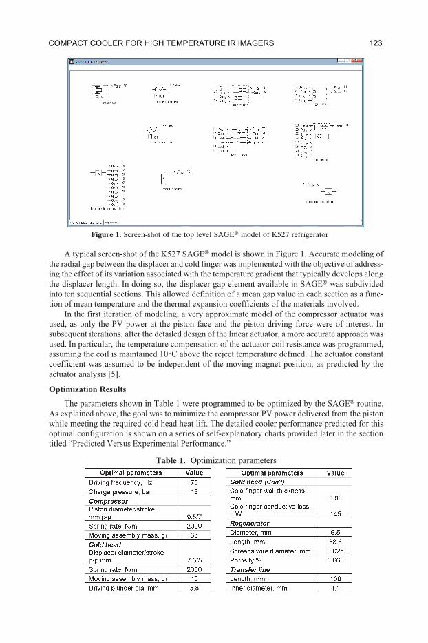
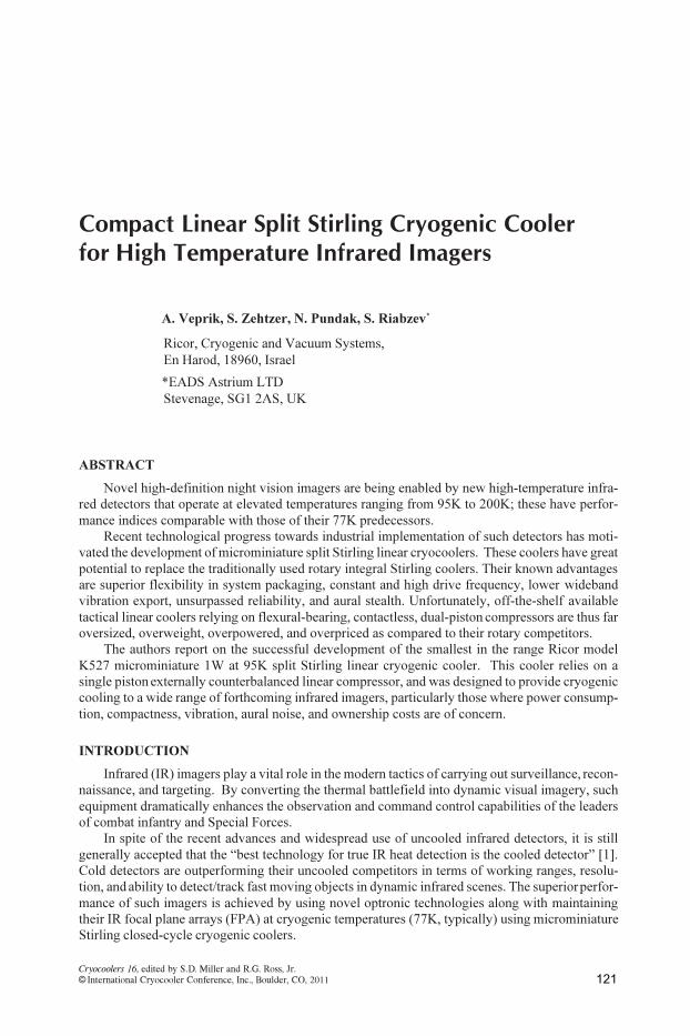
Figure 1. Screen-shot of the top level SAGE® model of K527 refrigerator
Table 1. Optimization parameters
A typical screen-shot of the K527 SAGE® model is shown in Figure 1. Accurate modeling of
the radial gap between the displacer and cold finger was implemented with the objective of address-
ing the effect of its variation associated with the temperature gradient that typically develops along
the displacer length. In doing so, the displacer gap element available in SAGE® was subdivided
into ten sequential sections. This allowed definition of a mean gap value in each section as a func-
tion of mean temperature and the thermal expansion coefficients of the materials involved.
In the first iteration of modeling, a very approximate model of the compressor actuator was
used, as only the PV power at the piston face and the piston driving force were of interest. In
subsequent iterations, after the detailed design of the linear actuator, a more accurate approach was
used. In particular, the temperature compensation of the actuator coil resistance was programmed,
assuming the coil is maintained 10°C above the reject temperature defined. The actuator constant
coefficient was assumed to be independent of the moving magnet position, as predicted by the
actuator analysis [5].
Optimization Results
The parameters shown in Table 1 were programmed to be optimized by the SAGE®
routine.
As explained above, the goal was to minimize the compressor PV power delivered from the piston
while meeting the required cold head heat lift. The detailed cooler performance predicted for this
optimal configuration is shown on a series of self-explanatory charts provided later in the section
titled “Predicted Versus Experimental Performance.”
123COMPACT COOLER FOR HIGH TEMPERATURE IR IMAGERS

DESCRIPTION OF MECHANICAL DESIGN
K527 Expander Unit
The expander unit comprises a “mass-spring,” pneumatically driven displacer-regenerator, as
is widely accepted across the industry. Needless to say, it is favorable to design such a displacer-
regenerator so that it operates it at or near its resonant frequency. The first benefit of such a resonant
tuning is that the displacer stroke achieves its maximum for a given pneumatic force delivered by
the compressor, or alternatively, the desired displacer stroke may be obtained at minimum pneu-
matic force delivery. The second benefit is that tuning the displacer to resonate delivers almost
automatically the desired 90º phase angle between displacer motion and the pressure pulses arriv-
ing through the transfer line from the compression space, as is needed for producing maximum
cooling [6]. The above two benefits contribute essentially to improving the displacer’s expansion
efficiency for a given acoustic power delivered by the compressor. Resulting from this is improved
heat pumping from the expansion space to which the heat payload is thermally linked. Since the
spring effect of the equivalent gaso-dynamic viscoelastic loading in the expander is negligibly small,
the inertia of the moving assembly and the equivalent elasticity of the above-mentioned spring
define the closeness to the resonance condition.
There are two different approaches to forming the above “spring” component. In the first ap-
proach, a helical wire spring, or, alternatively, two counter-facing preloaded helical wire springs,
are arranged to support the movable displacer-regenerator assembly from the stationary housing.
Using mechanical springs yields a compact design and convenient resonant tuning which appears
to be almost independent of environmental temperature. The inherent disadvantages of such a de-
sign are unreliable mechanical spring connection, radiation of acoustic noise, tiny metal debris
generation, and, most important, exertion of large side forces on the dynamic seals leading to exces-
sive friction, parasitic losses, and wear and tear.
In another implementation, a “pneumatic pillow” [7] may be formed by a plunger tail cycli-
cally protruding from the sealed rear space. This approach is widely accepted because of its com-
pactness and almost frictionless operation. Unfortunately, the spring rate of such a pneumatic spring
is a function not only of the rear space volume and plunger area, but also of the average pressure and
environmental temperature. Thus, these variables have a strong influence on the above resonant
frequency. An additional disadvantage is excessive overheating of the cold finger housing because
of the irreversible compression losses associated with cyclic compression of the gas sealed inside
this rear space that forms the “gas pillow.”
In the present design, the authors capitalize on using a highly accurate double starting helix
machined spring with integral retainers [8]. The high mechanical accuracy has been achieved using
precise EDM machining. Figure 2 shows a schematic (a) and an external photograph (b) of the
pneumatically driven expander [6].
K527 LINEAR COMPRESSOR
As is known, a single-piston compressor is a powerful source of exported vibration at its driv-
ing frequency and higher-order harmonics [9]. It is widely accepted, therefore, that a dual-piston
compressor, which “should-be” dynamically counterbalanced, is the solution of choice for inher-
ently vibration sensitive cooled IR applications. Several major cryogenic cooler vendors manufac-
ture microminiature (below 1.5W at 77K) split Stirling cryogenic coolers comprising dual-piston,
Figure 2. Schematic and external layout of a pneumatically driven expander
124 SMALL 50-80 K SINGLE-STAGE CRYOCOOLERS

(a) (b)
Figure 3. Schematics and external layout of a linear compressor
“moving magnet,” flexural bearing compressors [10, 11]. These are achieved, however, at the
expenses of size, weight, manufacturing costs, reduced electromechanical performance, and reli-
ability. Moreover, since the sub-compressors are not entirely similar (different piston-cylinder gaps
and friction forces, magnet force, driving coils resistances, etc) the residual vibration exported at
the driving frequency and higher-order harmonics is not really encouraging; reaching low levels of
vibration export may require additional vibration isolation, or sometimes active vibration cancella-
tion. With this in mind, the authors have rejected the dual-piston approach in favor of a single-
piston compressor design where vibration control relies on a field-proven combination of a high
frequency vibration isolator, and a tuned dynamic absorber, as explained, for example, in [12].
The single-piston K527 linear compressor is driven by a resonant “moving magnet” actuator.
This allows it to obtain a high coefficient of performance [5,6] and also allows the driving coil to be
separated from the working agent (Helium, typically), thus preventing the cooler interior from be-
ing contaminated by outgassing products originating from the wire insulation varnish. Having the
coils outside also eliminates the need for flying leads and potentially leaking feedthroughs. It is also
important to note that in such an approach, heatsinking the intrinsic copper losses from the exter-
nally located drive coil is much improved.
Figure 3 shows a schematic (a) and external photograph (b) of such a compressor. In Figure 3a,
the radially magnetized ring is placed movably between the stationary internal and external arma-
ture yokes, which are made of a magnetically soft material. The above yokes are shaped in such a
fashion so as to accommodate the driving coil carrying the AC current and to provide for the quasi
uniform distribution of the magnetic flux within the working air gap without oversaturating the
yoke’s material [5,6].
The above magnetic ring is bonded upon the magnet form, which is, in turn, rigidly attached to
the compression piston, arranged so as to slide freely inside the tightly matched cylinder liner being
placed inside the internal yoke.
For the sake of compactness, a double starting helix machined spring, connecting the movable
piston and stationary housing is placed inside the piston. A sliding piston/cylinder pair design pro-
vides important improvements in performance, compactness, manufacturing costs, ease of assem-
bly and maintenance. It replaces the “contactless” approach that relies on flexural bearings and
accurate (sometimes robotic) alignment and assembly [11]. The piston and cylinder liners are
tightly matched to 4μm radial clearance and are made of a special tribological material.
As described above, using a precise double starting helix machined spring allows improved
alignment and low friction forces along with eliminating metal debris generation. An additional
advantage of this approach is that the piston-cylinder sleeves may be matched more tightly as com-
pared to the above contactless design; this results in a substantial decrease in blowby losses. This
decision to abandon the flexure bearing design is based on the proven technology used currently in
the Ricor model K529N cryogenic cooler, where in the course of the accelerated life test the experi-
mental cooler accumulated in excess of 27,500 working hours (equivalent to 45,000 hours under
standard test profile). When investigating this experimental cooler’s failure, it appeared that an
electrical short in the driving coil happened due to overheating of the inappropriately chosen var-
125COMPACT COOLER FOR HIGH TEMPERATURE IR IMAGERS
(a) (b)
Figure 4. Experimental setup
nish type [13]. The “post mortem” inspection revealed that the outer diameter of the piston and
inner diameter of the cylinder liners were still within the manufacturing tolerances, and that the
working surfaces were free of abrasive scratches and wear.
Based on the theoretical analysis of [5,6], optimizing the “moving magnet” linear actuator
requires maintaining the ratio R¤Ù2 (R and Ù stand for the driving coil resistance and force/current
constant, respectively) at the lowest possible level. In an ideal case this means increasing the
“copper volume” and magnetic flux in the air gap along with using low resistive wire for making
the driving coil. No less important in this regard, is to also provide for effective heatsinking of the
Joule heating originating from the drive coil.
EXPERIMENTAL MAPPING
Experimental Setup
The experimental testing involved monitoring and data acquisition of electrical quantities like
voltage, current and power consumed by the linear compressor, cold finger temperature, piston and
displacer strokes, pressure pulse, and heat load applied to the cold finger tip.
Figure 4 shows pictures of the experimental setup. In Figure 4(a), the compressor and ex-
pander units of the K527 cryogenic cooler are placed at 90 degrees to each other on the Kistler
9272A dynamometer. This enables simultaneous monitoring and data acquisition of the vibration
export produced by the two above components.
Figure 4(b) shows the test bench and the dedicated notebook computer that provides closed-
loop temperature control operation of the cryocooler. The basic function of the test bench is to
monitor the cold finger temperature and produce a drive voltage of constant frequency for the
compressor unit. The magnitude of the voltage is varied to maintain the cold tip temperature at the
prescribed level under different working conditions.
Figure 5 shows a schematic of the experimental setup. The pressure P on the piston face is
monitored by a Kistler Type 603B1 pressure transducer placed inside a special adaptor, thus mak-
ing it a part of the transfer line. The electrical signals from the above pressure sensor P, motor
current I, and vibration forces Fc
(compressor) and Fe
(expander) are conditioned in the Bruel &
Kjaer Nexus charge amplifier and then fed to the multichannel Data Physics Quattro Signal Ana-
lyzer for data acquisition and digital signal processing.
Mapping and Post-Processing
The parameters of the K527 prototype unit were mapped experimentally as shown in Table 2,
by varying the coldtip electrical heat load while in temperature-controlled mode. Since the above
vibration forces Fc
and Fe
are products of the moving masses and accelerations, as explained in [9],
these signals were used for noninvasive monitoring of the piston and displacer motion.
126 SMALL 50-80 K SINGLE-STAGE CRYOCOOLERS

Further, the recorded data were post-processed, aiming at calculation of the piston and dis-
placer magnitudes, phase lag between them, and the PV power at the piston face. The postprocessing
assumption was that the measured dynamic signals were of a purely harmonic shape. In addition,
the actuator coil resistance loss was identified using the experimental results.
In Table 2, representing raw data, Qnet
stands for added heat load; Win
– power consumption;
I – motor current; Fc and F
e - vibration export produced by compressor and expander, respectively;
P – pressure on the piston face; P Fc - angle between pressure and compressor vibration force;
P Fe angle between pressure and expander vibration force.
Further, we use the following notations and formulae: õ - driving angular frequency; mp
- piston
assembly mass; md - displacer assembly mass, d
p - piston diameter; A
p = îd
p
2
¤4 - piston face area;
xp = F
c¤m
põ2
, xd = F
c¤m
dõ2
- piston and displacer magnitudes; xp
xd = P F
p - P F
d - phase
lag between piston and displacer positions; dV = õxpA
p - volumetric speed amplitude; P dV=
P Fp+ 90°¶- phase lag between pulse oscillations and compressor volumetric speed;
WPV
=PdV cos (P dV ) - PV power at piston face; Wcoil
¶=¶I2
R¶– resistance loss in actuator coil.
Table 3 summarizes the results of the postprocessing done using the above equations.
Table 2. Experimental mapping outcomes
Figure 5. Schematic of experimental setup
127COMPACT COOLER FOR HIGH TEMPERATURE IR IMAGERS

(a) (b)
(c) (d)
Figure 6. Verification charts of K527 SAGE®
model versus experimental data.
Table 3. Postprocessing outcomes
PREDICTED VERSUS EXPERIMENTAL PERFORMANCE
The purpose of the experimental testing was to compare the actual cooler performance with the
outcomes of the theoretical predictions based on the above computer modeling. This testing was
undertaken primarily to validate the computer model with the purpose of scaling the cryogenic
cooler to different working conditions. As a result, a number of performance charts were generated
using the SAGE®
model and further superimposed on the experimental data.
All the validated parameters are shown graphically in Figures 6 and 7 versus PV power avail-
able at the piston face. This sort of data presentation was chosen to allow a virtual separation
between thermodynamic and electromechanical circuits in the modeled cryocooler.
128 SMALL 50-80 K SINGLE-STAGE CRYOCOOLERS
(a) (b)
(c) (d)
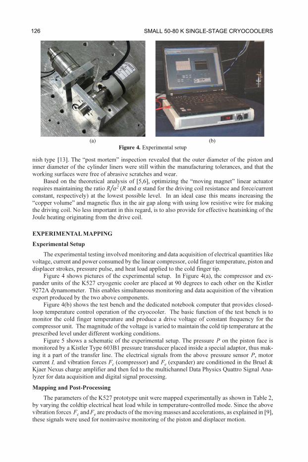
Figure 7. Continued verification charts for K527 SAGE®
model versus experimental data.
From the eight charts in Figures 6 and 7, it is clear that the modeled data agree reasonably well
with the measured parameters. The only exception is the input power of the compressor actuator,
which does differ noticeably from the experimental data. Concluding the verification work, it is
obvious that the SAGE®
model does reasonably reflect the reality in terms of thermodynamics,
despite the noticeable discrepancy in the electrical input power. The discrepancy is most likely to be
related to iron and eddy-current losses in the compressor actuator, which could not be precisely
addressed in the SAGE®
environment. From Figure 7d, further essential improvements may be
available by redesigning the linear actuator.
Cooler Study at the Point of Optimal Design
As was mentioned above, the K527 cryogenic cooler has been optimized to maintain a 750mW
payload load (e.g. infrared FPA) at 95K, while rejecting its heat at a temperature of 28°C. Since the
cooler is intended for operation over the wide range of reject temperatures, and therefore heat lifts,
it was important to evaluate the performance of the cooler working at 95K over the entire range of
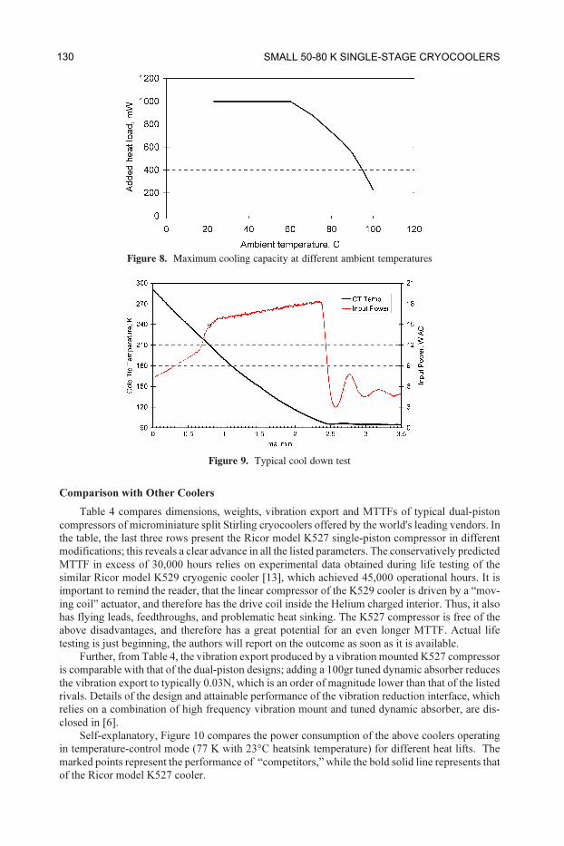
working conditions. Figure 8 shows the typical dependence of the maximum added heat load on
environmental temperature at 45W AC max. From Figure 9, this cooler might be characterized as
1W at 95K. During the typical cool down test from 290K to 95K, a thermal mass of approximately
200¶J was affixed to the cold finger tip to mimic the mass of a real detector. During the 45s soft start
the power consumption was gradually increased from 7 to 15W AC. Further increases up to 18W
AC took place at constant driving voltage. Figure 9 portrays the time variation of the cold tip
temperature and the input power during the above test. The data indicate a less than 2.5 min cool-
down time and a smooth transition into the controllable mode. The cooldown time may be further
improved by shortening the soft start phase and increasing the maximum power up to 30W AC.
129COMPACT COOLER FOR HIGH TEMPERATURE IR IMAGERS
Comparison with Other Coolers
Table 4 compares dimensions, weights, vibration export and MTTFs of typical dual-piston
compressors of microminiature split Stirling cryocoolers offered by the world's leading vendors. In
the table, the last three rows present the Ricor model K527 single-piston compressor in different
modifications; this reveals a clear advance in all the listed parameters. The conservatively predicted
MTTF in excess of 30,000 hours relies on experimental data obtained during life testing of the
similar Ricor model K529 cryogenic cooler [13], which achieved 45,000 operational hours. It is
important to remind the reader, that the linear compressor of the K529 cooler is driven by a “mov-
ing coil” actuator, and therefore has the drive coil inside the Helium charged interior. Thus, it also
has flying leads, feedthroughs, and problematic heat sinking. The K527 compressor is free of the
above disadvantages, and therefore has a great potential for an even longer MTTF. Actual life
testing is just beginning, the authors will report on the outcome as soon as it is available.
Further, from Table 4, the vibration export produced by a vibration mounted K527 compressor
is comparable with that of the dual-piston designs; adding a 100gr tuned dynamic absorber reduces
the vibration export to typically 0.03N, which is an order of magnitude lower than that of the listed
rivals. Details of the design and attainable performance of the vibration reduction interface, which
relies on a combination of high frequency vibration mount and tuned dynamic absorber, are dis-
closed in [6].
Self-explanatory, Figure 10 compares the power consumption of the above coolers operating
in temperature-control mode (77 K with 23°C heatsink temperature) for different heat lifts. The
marked points represent the performance of “competitors,” while the bold solid line represents that
of the Ricor model K527 cooler.
Figure 8. Maximum cooling capacity at different ambient temperatures
Figure 9. Typical cool down test
130 SMALL 50-80 K SINGLE-STAGE CRYOCOOLERS
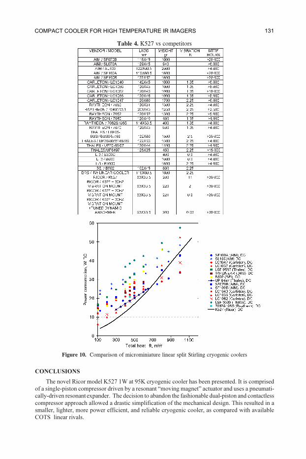
Table 4. K527 vs competitors
CONCLUSIONS
The novel Ricor model K527 1W at 95K cryogenic cooler has been presented. It is comprised
of a single-piston compressor driven by a resonant “moving magnet” actuator and uses a pneumati-
cally-driven resonant expander. The decision to abandon the fashionable dual-piston and contactless
compressor approach allowed a drastic simplification of the mechanical design. This resulted in a
smaller, lighter, more power efficient, and reliable cryogenic cooler, as compared with available
COTS linear rivals.
Figure 10. Comparison of microminiature linear split Stirling cryogenic coolers
131COMPACT COOLER FOR HIGH TEMPERATURE IR IMAGERS

This cryogenic cooler is ideally suited for a wide range of forthcoming high-temperature electro
optical instrumentation like portable handheld cameras, thermal weapon sights, ground fixed and
vehicle mounted surveillance cameras, gyrostabilized imagers, etc.
REFERENCES
1. Gething, M., J., “Seeking the heat in the night,” Jane’s International Defense Review, 38, 42-47 (2005).
2. Glozman, A., Harush, E., Jacobsohn, E., Klin, O., Klipstein, P., Markovitz, T., Nahum V., Saguy E.,
Oiknine-Schlesinger, J., Shtrichman, I., Yassen, M., Yofis, B. and Weiss, E., “High performance InAlSb
MWIR detectors operating at 100K and beyond,” Proc. SPIE 6206, 62060M (2006).
3. Tribolet, P., Costa, P., Fillon, P., Manissadjian, A. and Chorier, P., “Large staring arrays at Sofradir,”
Proc. SPIE 4820, 418 (2003).
4. Tsao, S., Lim, H., Zhang, W. and Razeghi, M., “High operating temperature 320×256 middlewavelength
infrared focal plane array imaging based on an InAs/InGaAs/InAlAs/InP quantum dot infrared photo-
detector,” Appl. Phys. Lett. 90, 201109 (2007).
5. Veprik, A., Vilenchik, H, Riabzev, S. and Pundak, N., “Microminiature linear split Stirling cryogenic
cooler for portable infrared imagers,” Proc. SPIE 6542, 65422F (2007).
6. A. Veprik, S. Zechtzer and N. Pundak, “Split Stirling linear cryogenic cooler for a new generation of
high temperature infrared imagers,” Proc. SPIE 7660, 76602K (2010).
7. Walker, G., Cryogenic coolers, Plenum Press, New York (1983).
8. Curven, P.,W., Newell, R.,V, “Resonant piston pump,” USA Patent #3,588,291 (1971).
9. Riabzev, S., V., Veprik, A.,M. and Pundak, N., “Technical diagnostics of linear split Stirling cryo-
cooler through the analysis of self-induced forces,” Adv. in Cryogenic Engineering, Vol. 47B, Amer.
Institute of Physics, Melville, NY (2002), pp. 1141-1148.
10. Mullie, J.,C., Bruins, P.,C., Benschop, T. and Meijers, M., “Development of the LSF95xx 2nd genera-
tion flexure bearing coolers,” Proc. SPIE 5783, 178 (2005).
11. Rühlich, I., Wiedmann, T., Mai, M. and Rosenhagen C., “Flexure bearing compressor in the onewatt
linear (OWL) envelope,” Proc. SPIE 6542, 65422I (2007).
12. Veprik, A., M., Babitsky, V.,I, Pundak, N. and Riabzev S., “Vibration control of linear split Stirling
cryogenic cooler for airborne infrared application,” Journal of Shock and Vibration 7(6) (2000), pp.
363-379.
13. Nachman, I., Veprik, A. and Pundak, N., “Life test result of Ricor K529N 1W linear cryocooler,” Proc.
SPIE 6542, 65422G (2007).
14. Gedeon D., Sage Pulse Tube Model-Class Reference Guide, Gedeon Associates (1999).
15. Veprik, A.,M., Babitsky, V.,I., Pundak, N. and Riabzev, S., “Vibration control of linear split Stirling
cryogenic cooler for airborne infrared application,” Journal of Shock and Vibration 7(6) (2000), pp.
363-379.
132 SMALL 50-80 K SINGLE-STAGE CRYOCOOLERS