DOTA Retrofit Feasibility Study...
52
RETROFIT FEASIBILITY STUDY Honolulu International Airport Small Municipal Separate Storm Sewer System File No. HI S000005 Prepared For: State of Hawaii Department of Transportation Airports Division 400 Rodgers Boulevard, Suite 700 Honolulu, Hawaii 96819-1880 August 2010 Version 1.0
Transcript of DOTA Retrofit Feasibility Study...

RETROFIT FEASIBILITY STUDY Honolulu International Airport
Small Municipal Separate Storm Sewer System
File No. HI S000005
Prepared For:
State of Hawaii Department of Transportation
Airports Division 400 Rodgers Boulevard, Suite 700
Honolulu, Hawaii 96819-1880
August 2010
Version 1.0

Retrofit Feasibility Study i August 2010 Honolulu International Airport Version 1.0 Small Municipal Separate Storm Sewer System
TABLE OF CONTENTS
1.0 CERTIFICATION AND LIMITATIONS................................................................................... 1
2.0 INTRODUCTION ......................................................................................................................... 2
2.1 TASKS .......................................................................................................................................... 2 2.2 SPECIFIC CONDITIONS AT HNL ................................................................................................... 2
3.0 HNL SMALL MS4 CHARACTERISTICS................................................................................. 3
3.1 HNL SMALL MS4 SUMMARY...................................................................................................... 4 3.2 CLIMATOLOGIC CONDITIONS ...................................................................................................... 4 3.3 GEOLOGY AND HYDROGEOLOGY ................................................................................................ 5
3.3.1 Regional Geology ..................................................................................................................................5 3.3.2 Site Geology...........................................................................................................................................5 3.3.3 Regional Hydrogeology .........................................................................................................................6 3.3.4 Site Hydrogeology .................................................................................................................................6
4.0 WATERSHED CHARACTERIZATION.................................................................................... 7
4.1 MANUWAI WATERSHED .............................................................................................................. 7 4.2 KEEHI WATERSHED ..................................................................................................................... 7
5.0 RETROFIT GOALS...................................................................................................................... 8
5.1 REDUCE POLLUTANTS OF CONCERN ........................................................................................... 8 5.2 TRAPPING TRASH AND FLOATABLES........................................................................................... 9 5.3 REDUCE RUNOFF VOLUMES ........................................................................................................ 9 5.4 STORM WATER DEMONSTRATION AND EDUCATION................................................................... 9 5.5 PERFORMANCE GOAL SUMMARY ................................................................................................ 9
6.0 DESKTOP ANALYSIS ............................................................................................................... 10
6.1 STORAGE RETROFITS................................................................................................................. 10 6.1.1 SR-1 Modify Existing Ponds ................................................................................................................10 6.1.2 SR-2 Storage above Roadway Culverts ...............................................................................................10 6.1.3 SR-3 New Storage below Outfalls........................................................................................................11 6.1.4 SR-4 Treatment in the Conveyance System..........................................................................................11 6.1.5 SR-5 Storage in Transport Right of Ways............................................................................................11 6.1.6 SR-6 Large Parking Lot Retrofits ........................................................................................................11
6.2 ON-SITE RETROFITS .................................................................................................................. 12 6.2.1 OS-7 Hotspot Operations.....................................................................................................................12 6.2.2 OS-8 Small Parking Lot Retrofits ........................................................................................................12 6.2.3 OS-9 Individual Streets........................................................................................................................13 6.2.4 OS-10 Individual Rooftops...................................................................................................................14 6.2.5 OS-11 Little Retrofits ...........................................................................................................................14 6.2.6 OS-12 Landscapes – Hardscapes ........................................................................................................14 6.2.7 OS-13 Underground Retrofits..............................................................................................................14
7.0 RETROFIT RECONNAISSANCE INVESTIGATION (RRI)................................................ 15
7.1 STORM DRAIN RETROFITS ......................................................................................................... 15 7.2 HOT SPOT RETROFITS................................................................................................................ 15
7.2.1 Triturators ...........................................................................................................................................15 7.2.2 Maintenance Baseyard Sweeper Rubbish ............................................................................................16 7.2.3 Ualena Street Tenants..........................................................................................................................16
7.3 RANKING CRITERIA ................................................................................................................... 16 7.4 DERIVING DATA FOR POLLUTANT LOAD REDUCTIONS & COST ............................................... 18

Retrofit Feasibility Study ii August 2010 Honolulu International Airport Version 1.0 Small Municipal Separate Storm Sewer System
7.5 PROJECT RECOMMENDATIONS .................................................................................................. 19
8.0 SUMMARY .................................................................................................................................. 21
9.0 REFERENCES............................................................................................................................. 22
TABLES
TABLE 1: BASINS AND BASIN AREAS............................................................................................................ 3 TABLE 2: SMALL MS4 DRAINAGE STRUCTURES .......................................................................................... 4 TABLE 3: IMPAIRED RECEIVING WATERS ..................................................................................................... 8 TABLE 4: RETROFIT PERFORMANCE GOALS ................................................................................................. 9 TABLE 5: HNL PARKING LOTS ................................................................................................................... 13 TABLE 6: SCORING CRITERIA USED FOR RANKING .................................................................................... 16 TABLE 7: POLLUTANT LOAD CALCULATION PARAMETERS ........................................................................ 18 TABLE 8: UNIT COSTS OF RETROFIT BMPS ................................................................................................ 18 TABLE 9: POLLUTANT REMOVAL EFFICIENCY OF RETROFIT BMPS........................................................... 19 TABLE 10: FINAL LIST OF POTENTIAL RETROFIT BMPS AT HNL .............................................................. 20
ATTACHMENTS ATTACHMENT I – FIGURES ATTACHMENT II – AIRPORT MODERNIZATION PLAN RENDERING ATTACHMENT III - STORM DRAIN RANKING AND EXAMPLE RETROFIT ATTACHMENT IV - BLANK RRI FORM AND FIELD GUIDE ATTACHMENT V - DESKTOP ANALYSIS RETROFIT LIST ATTACHMENT VI - FINAL POTENTIAL RETROFIT LIST AND RRI FORMS ATTACHMENT VII - HOTSPOT RRI FORMS

Retrofit Feasibility Study 1 August 2010 Honolulu International Airport Version 1.0 Small Municipal Separate Storm Sewer System
1.0 CERTIFICATION AND LIMITATIONS
EnviroServices & Training Center (ETC), LLC has completed this Retrofit Feasibility Study for the Honolulu International Airport (HNL). ETC’s findings and conclusions presented in this report are professional opinions based solely upon visual observations of sites within HNL, government regulations, and information available about storm water retrofits at the time of this study. This report is intended for the sole use of the Client, Department of Transportation – Airports Division, exclusively for HNL. The scope of services performed in execution of this project may not be appropriate for satisfying the needs of other users, and any use or reuse of this report or the findings and designs presented herein is unauthorized and at the sole risk of said user. ETC makes no guarantee or warranty; either expressed or implied, except that our services are consistent with good commercial or customary practices designed to conform to acceptable industry standards and governmental regulations. No warranty or representation, expressed or implied, is included or intended in its proposal, contracts, or reports. The retrofits proposed in this study are evaluated on a “concept” level and will require final engineering details prior to construction. The design engineer will hold the ultimate responsibility to determine whether a proposed retrofit can be implemented based on the final engineering study and design. DOTA will implement those retrofits approved by a certified engineer as funds become available.
Katie Davis Environmental Scientist
Clifford Wassman Engineer

Retrofit Feasibility Study 2 August 2010 Honolulu International Airport Version 1.0 Small Municipal Separate Storm Sewer System
2.0 INTRODUCTION
As part of the National Pollutant Discharge Elimination System (NPDES) Small Municipal Separate Storm Sewer System (MS4) permit requirements for Honolulu International Airport (HNL), State of Hawaii, Department of Transportation, Airports Division (DOTA) will complete a retrofit feasibility study on the existing MS4 discharges to receiving waters listed pursuant to Section 303(d) of the Clean Water Act for pollutants such as sediment, siltation, turbidity, and/or trash. Under this study, DOTA will plan, strategize, and implement retrofits that shall include water quality Best Management Practices (BMPs).
2.1 Tasks
DOTA made extensive use of the Center for Watershed Protection’s national publication on storm water retrofitting, Urban Stormwater Retrofit Practices (Schueler et al., 2007) (USRM) in order to indentify and complete the tasks involved in a retrofit study. Task 1 – Develop Performance Goals – Performance goals were identified for HNL
based on the 303(d) list of impaired waters, known pollutants or issues in the current MS4, and goals of the storm water program as a whole.
Task 2 - Desktop Analysis – A desktop analysis of HNL and the two associated watersheds was conducted to develop an initial ranking of retrofit potential for DOTA spaces based on the performance goals identified in Task 1.
Task 3 – Retrofit Inventory – An inventory of sites was compiled that had the potential for the inclusion of retrofits based on the desktop analysis in Task 2.
Task 4 – Field Investigation – Fieldwork was conducted on July 19, 2010, by ETC and focused on the sites identified in Task 3. Evaluations of the sites were recorded on the Retrofit Reconnaissance Investigation (RRI) form from the USRM.
Task 5 – Retrofit Evaluation & Ranking – Retrofit projects were evaluated based on pollutant load reductions, cost-effectiveness, and other screening factors derived from the initial performance goals. These projects were discussed with DOTA engineers to determine the strongest candidates for design work.
Task 6 – Final Report – A final report was drafted detailing the conceptual retrofits selected for further design and implementation at HNL.
2.2 Specific Conditions at HNL
The retrofit feasibility study at HNL took into consideration additional restrictions imposed on projects due to its status as an active airport. Federal Aviation Administration (FAA) rules prohibit building wildlife habitats due to the hazards that birds may pose to aircraft safety. Therefore, large wetlands and other retrofits that have the potential to attract birds will not be considered in this study. Additionally, at the time of this study, an airport modernization plan has been developed. Therefore, potential retrofits were also evaluated based on the current modernization plans in order to determine whether the future construction would have an impact on the implementation of that retrofit.

Retrofit Feasibility Study 3 August 2010 Honolulu International Airport Version 1.0 Small Municipal Separate Storm Sewer System
3.0 HNL SMALL MS4 CHARACTERISTICS
DOTA is responsible for operating and maintaining the Honolulu International Airport (HNL) and the associated infrastructure, including the storm water drainage system (Small MS4) (Attachment I, Figure 1). HNL is divided into various basins based on the drainage in each particular area (Table 1).
TABLE 1: BASINS AND BASIN AREAS
BASIN AREA*
(ACRE) WATERSHED BASIN
AREA*
(ACRE) WATERSHED A1 18.72 Keehi B17 73.47 Manuwai
A2 102.64 Keehi B18 52.56 Manuwai
A3 54.46 Keehi C1 309.03 Manuwai
A4 75.53 Manuwai C2 118.46 Manuwai
A5 9.08 Manuwai D1 10.76 Manuwai
A6 124.72 Manuwai D2 5.47 Manuwai
A7 18.02 Manuwai D3 5.62 Manuwai
A8 59.08 Manuwai D4 9.48 Manuwai
A9 46.37 Manuwai D5 5.58 Manuwai
A10 184.54 Manuwai D6 6.16 Manuwai
B3 189.00 Manuwai D7 8.37 Manuwai
B4 103.63 Manuwai D8 3.43 Manuwai
B5 36.63 Manuwai D9 7.16 Half/Half
B6 45.90 Manuwai D10 212.98 Half/Half
B7 70.14 Manuwai D11 11.05 Keehi
B8 50.26 Manuwai D12 4.21 Keehi
B9 89.97 Manuwai D13 7.44 Keehi
B10 52.03 Manuwai D14 29.93 Keehi
B11 13.08 Manuwai D15 10.23 Keehi
B12 24.58 Manuwai D16 7.34 Keehi
B13 51.70 Manuwai D17 8.22 Manuwai
B15 14.22 Manuwai E 39.22 Keehi
B16 38.88 Manuwai
*Areas are approximate based on the HNL autocad drainage map.

Retrofit Feasibility Study 4 August 2010 Honolulu International Airport Version 1.0 Small Municipal Separate Storm Sewer System
3.1 HNL Small MS4 Summary
HNL contains four active runways, thirty taxiways, and one maintenance baseyard within 4,520 acres on southern Oahu (Attachment I, Figure 1). Over 20 million visitors are transported through the airport by 27 international and domestic carriers, 3 interisland airlines, and 4 commuter airlines. This area is also utilized by industrial and commercial tenants that perform activities ranging from aircraft maintenance and fueling to autobody repair and cargo operations. These areas are divided into separate basins (Table 1) which drain storm water through the Small MS4 structures which are summarized in Table 2.
TABLE 2: SMALL MS4 DRAINAGE STRUCTURES
STRUCTURE TYPE TOTAL NO.Box Culvert 33 Catch Basin 249 Head Wall 14 Inlet 795 Manhole 401 Outfall 152 Evaporation Pond 3 Trench Drain 47 Open Channels 6 Oil Water Separators 97
Storm water protection has been a concern at HNL prior to this retrofit feasibility study. Several permanent storm water Best Management Practices (BMPs) are already in place at HNL. These retrofits include: 97 oil water separators, 68 of which are operated and maintained by DOTA and 29 by
tenants; 3 evaporation ponds that receive water from wash pads and hardstand areas where
aircraft maintenance is conducted; 6 channels stabilized with vegetation; 1 Koi pond garden located near the Central Concourse; 1 swale between Taxiway “A” and Runway “8L” treating water from Manuwai Canal;
and Small filter strips between facilities and the roadway drainage on the following streets:
o Lagoon Drive o Palekona Street o Iako Place o Lauhoe Place o Pohakulana Place o Keehi Place o Mokuea Place o Nakolo Place o Kapalulu Place o Kaulele Place o Iolana Place

Retrofit Feasibility Study 5 August 2010 Honolulu International Airport Version 1.0 Small Municipal Separate Storm Sewer System
o Aolele Street o Paiea Street o Elliot Street.
3.2 Climatologic Conditions
The main features of Oahu’s climate include mild temperatures throughout the year ranging from 88˚F (31˚C) to 74˚F (23˚C) and moderate humidity of 53% during the day. The northeasterly trade winds generated by a high pressure center north of the islands are the dominant factor that governs the climate in Hawaii. Two mountain ranges on Oahu, the Koolau Mountains which extend along the northeastern side of the island and the Waianae Mountains which extend along the southwestern side of the island, influence every aspect of the climate. Both mountain ranges serve to block the trade wind moisture and as a result, showers occur almost daily on the windward side while on the leeward side showers are light. The trade winds are generally strongest during the summer (May through October) and are periodically disrupted by storms in the winter (October through April), which result in heavy rain and thunderstorms throughout the island. At the site, the average annual rainfall reported by the U.S. Department of Agriculture is between 20 to 25 inches, most of which occurs during the winter months.
3.3 Geology and Hydrogeology
3.3.1 Regional Geology
Oahu is formed by the erosional remnants of two shield volcanoes. These are the Waianae range to the west and the Koolau range to the east. The Waianae volcano is estimated to have formed 2.4 to 3.6 million years before present. It consists of a tholeiitic lava shield with a thick cap of transitional to alkalic rock. Rejuvenation-stage volcanics of undifferentiated age occur in Kolekole Pass and on the south flank of the Waianae shield. Dike orientations define northwest and southwest rift zones (Macdonald, et al., 1983).
The Koolau volcano is estimated to have formed 1.8 to 2.6 million years before the present. It consists of a tholeiitic lava shield and lacks an alkalic cap. It has well defined major dike complex trending northwest-southwest. A third, minor rift zone referred to as the Kaau rift trends southward from Kaau crater, near the upland crest of the Koolau Ridge. After a long dormant period and periods of deep erosion, the Koolau volcano developed abundant and scattered rejuvenation-stage vents, typically aligned on northeast-striking fissures (Macdonald, et al., 1983).
3.3.2 Site Geology
The soil at the site is mapped as fill land, mixed (FL). FL consists of dredged material from the ocean, material from nearby areas, garbage, and general material. This land type occurs near Pearl Harbor and in areas of Honolulu adjacent to the ocean. The land type is used for urban development including airports, housing areas, and industrial facilities (USDA, 1972). In addition, previous investigations encountered coralline sand to a depth of 7 feet below ground surface (bgs) and fine grained, well sorted, gray sand below 7 ft bgs (J. R. Herold & Associates, 1999). At a depth below 11 to 13 ft bgs, it was noted that the soil type appeared to be dense, gray gravel (Dames & Moore, 1993).

Retrofit Feasibility Study 6 August 2010 Honolulu International Airport Version 1.0 Small Municipal Separate Storm Sewer System
3.3.3 Regional Hydrogeology
The primary drinking water in the Hawaiian Islands is drawn from basal groundwater. Basal groundwater is formed by rainwater percolating down through the residual soils and permeable volcanic rock. The portion of the island situated below sea level, except within rift zones of the volcanoes, is saturated with ocean salt water and thus forms a basal lens called the "Ghyben-Herzberg" lens. A zone of transition between the fresh groundwater and the ocean salt water occurs due to the constant movement of the interface as a result of tidal fluctuations, seasonal fluctuations in recharge and discharge and aquifer development (Macdonald, et al., 1983).
Downward percolation of rainwater may be stopped by impermeable layers such as dense lava flows, alluvial clay layers and volcanic ash. The groundwater then forms a perched or high level aquifer, which is not in contact with salt water. Recharge of the aquifer occurs in areas of high rainfall, which are the interior mountainous areas. The groundwater flows from the recharge areas to the areas of discharge along the shoreline. Frictional resistance to groundwater flow causes it to pile up within the island until it attains sufficient hydraulic head to overcome friction. Thus, basal groundwater tends to slope toward the shoreline.
3.3.4 Site Hydrogeology
The site is underlain by the Moanalua Aquifer System, which is part of the Honolulu Aquifer Sector on the island of Oahu. The aquifer is classified by Mink and Lau, 1990, with the system identification number 30104116 (23321). This system includes an unconfined basal aquifer in sedimentary (nonvolcanic) lithology. The groundwater in this aquifer has a moderate salinity (1,000 to 5,000 mg/l Cl-) making it neither a drinking water source nor ecologically important. The groundwater is also described as replaceable with a high vulnerability to contamination.
The site is further underlain by a second aquifer of the same system. The aquifer is a confined, basal aquifer in flank compartments, and is classified with the system identification number 30104121 (11113). The groundwater in this aquifer is fresh with less than 250 mg/l Cl- and is currently used as a drinking water source. It is also described as irreplaceable with a low vulnerability to contamination (Mink and Lau, 1990).

Retrofit Feasibility Study 7 August 2010 Honolulu International Airport Version 1.0 Small Municipal Separate Storm Sewer System
4.0 WATERSHED CHARACTERIZATION
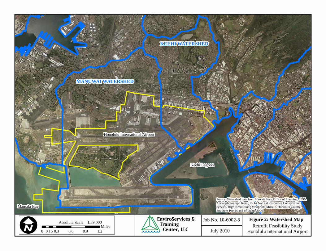
The retrofit feasibility study was conducted using a drainage area approach, which involves assessing and prioritizing water quality issues according to specified drainage areas to develop and implement BMPs. The Honolulu International Airport is on the discharge end of two watersheds, Manuwai and Keehi, as defined by the Hawaii Statewide Geographic Information Systems (GIS) Program maintained by the Office of Planning (Attachment I, Figure 2). However, DOTA can only implement retrofits in areas within HNL due to land ownership concerns. Therefore, other areas in these two watersheds were not included in the retrofit analysis.
4.1 Manuwai Watershed
The Manuwai Watershed is located on the southern portion of the island of Oahu and contains 4210.231 acres of land. The Manuwai Canal is the surface water body in this watershed that drains the airport as well as Hickam Air Force Base. The canal flows south through HNL to Ahua Pond, which discharges to Mamala Bay. This watershed contains the majority of HNL, including the terminals, a majority of the runways and taxiways, hardstands, as well as industrial and commercial tenants along Lagoon drive. The northern and western portions of the watershed, consisting of over 50 percent of the watershed, are used by the Federal Government for Hickam Air Force Base, military housing, and golf courses. DOTA has developed a relationship with the military in order to jointly comply with environmental requirements in this area. Mamala Bay (oceanic) is listed on the 303(d) list for impaired water bodies and the constituents of concern include total nitrogen and chlorophyll a.
4.2 Keehi Watershed
The Keehi Watershed is located on southern portion of the island of Oahu and encompasses 1578.23 acres of land. There are no surface water bodies that drain the area with the exception of Kaloaloa Canal, which flows east along Aolele Street to Keehi Lagoon. The majority of storm water is directed to the City and County of Honolulu’s MS4 or the Federal Government’s MS4. This watershed contains the eastern portion of HNL, including the baseyard, rental cars, and industrial tenants on Ualena Street. Additionally, the area north of HNL contains several mixed industrial businesses, military housing, residential areas, and a golf course. The western portion of the Keehi Lagoon Park is also included in this watershed. Keehi Lagoon is listed on the 303(d) list for impaired water bodies and the constituents of concern include nutrients (total nitrogen, nitrates and nitrites, total phosphorus), chlorophyll a, enterococci, turbidity, and total suspended solids.

Retrofit Feasibility Study 8 August 2010 Honolulu International Airport Version 1.0 Small Municipal Separate Storm Sewer System
5.0 RETROFIT GOALS
Storm water retrofitting involves the redesign and installation of storm water BMPs in areas of existing development to meet a retrofit goal. The retrofit goals identified for the HNL Small MS4, in order of priority, include:
1. Reduce Pollutants of Concern 2. Trapping Trash and Floatables 3. Reduce Runoff Volumes 4. Storm Water Demonstration and Education
5.1 Reduce Pollutants of Concern
The HNL Small MS4 discharges to Keehi Lagoon and Mamala Bay in southern Oahu. Since, HNL activities are centralized within their property boundaries, DOTA shall only be concerned with the impairments related to these water bodies. In addition to the 303(d) list of impaired water bodies (2004), State of Hawaii, Department of Health (DOH) has also established the list of impaired water bodies on Oahu in the State of Hawaii Water Quality Monitoring and Assessment Report (2006).
TABLE 3: IMPAIRED RECEIVING WATERS
WATER BODIES POLLUTANTS FROM 303(D) LIST, 2004
POLLUTANTS FROM WATER
QUALITY MONITORING AND
ASSESSMENT REPORT, 2006
Keehi Lagoon (Point X)
Enterococci Total Nitrogen Chlorophyll a Total Phosphorus
Enterococci Total Nitrogen Chlorophyll a Total Phosphorus
Keehi Lagoon waters and nearshore waters to 30’ from lagoon mouth to Pearl Harbor
Nutrients Turbidity Suspended Solids
Nutrients Turbidity Suspended Solids Total Nitrogen Nitrates + Nitrites Total Phosphorus
Mamala Bay (oceanic) Total Nitrogen Chlorophyll a
Total Nitrogen Chlorophyll a
HNL shall target the following list of pollutants identified from Table 3 for retrofit projects under the scope of this study.
1. Suspended Solids / Turbidity 2. Total Nitrogen 3. Nitrates + Nitrites 4. Total Phosphorus 5. Chlorophyll a 6. Enterococci 7. Oil and Grease

Retrofit Feasibility Study 9 August 2010 Honolulu International Airport Version 1.0 Small Municipal Separate Storm Sewer System
At the time of this report, there are no established Total Maximum Daily Loads (TMDLs) or Waste Load Allocations (WLA) for Keehi Lagoon and Mamala Bay. Therefore, there are no quantitative target levels for the pollutants of concern. However, DOTA shall strive to reduce pollution and to improve water quality by implementing water quality BMPs. Total Phosphorus will be used as an indicator pollutant for the others listed above and retrofits will strive to reduce the indicator pollutant by 25%. This retrofit study will evaluate TP removal efficiencies based on data obtained from existing literature and manufacturer’s specifications. Implemented BMPs may not reach the 25% removal goal.
5.2 Trapping Trash and Floatables
This retrofit goal was selected based on reports from the maintenance crew and contractors at HNL, which indicated that significant volumes of trash were being removed from the storm drains and along the coastline (Attachment III). Therefore, DOTA will seek to install BMPs that will prevent the trash and debris from impacting the receiving waters.
5.3 Reduce Runoff Volumes
Due to the nature of activities at HNL, large amounts of impervious cover have been constructed in the area. The impervious cover leads to increases in peak discharge, velocity, and volume of storm water runoff as well as increased pollutant loads. Reducing runoff volume also reduces pollutants by allowing storm water to infiltrate the ground prior rather than discharge to the receiving water through the MS4.
5.4 Storm Water Demonstration and Education
In order to promote education and stewardship, demonstration retrofits may be installed in a public area to treat localized runoff and introduce new storm water technologies.
5.5 Performance Goal Summary
Table 4 contains the goals that will be used to evaluate potential retrofits at HNL.
TABLE 4: RETROFIT PERFORMANCE GOALS
DESCRIPTION PRIMARY PERFORMANCE GOALS Pollutant Removal Retrofits/BMPs shall achieve at least 25% reduction from existing, on-
site total phosphorus loads for areas treated by retrofit/BMPs. Provide retrofit/BMP designs that also address removal of sediment as well as oil and grease loads as priority pollutants.
Trap Trash and Floatables Retrofits/BMPs shall achieve at least 25% reduction in existing, on-site trash and other floatables.
Reduce Runoff Volumes Retrofits shall promote infiltration and overall reduction in runoff volume to the extent achievable.
Education and Outreach Provide outdoor learning and community outreach opportunities on DOTA land.
DESCRIPTION SECONDARY BENEFITS Quick Implementation Projects Indentify quick implementation projects (constructed within 1 year)
based on existing CIP projects, availability of funds, projects underway, etc.
Specific Problems Identify retrofits for problem areas such as Ualena Street tenants, Baseyard sweeper rubbish, and the triturators.

Retrofit Feasibility Study 10 August 2010 Honolulu International Airport Version 1.0 Small Municipal Separate Storm Sewer System
6.0 DESKTOP ANALYSIS
The storm water retrofit assessment was divided into two focus areas, storage retrofits and on-site retrofits. Storage retrofits were evaluated by examining the drainage canals and major outfalls at HNL. On-site retrofits were evaluated by examining areas of significant industrial activity such as the baseyard facility and aircraft hardstands at HNL. Due to leasing conflicts, tenant areas were not evaluated as a part of this retrofit study, except in areas of historical issues. The desktop analysis was conducted using a basin-by-basin approach to locating potential retrofits. Data used in the desktop analysis included the following: Drainage Map – The autocad map developed for HNL included all storm drainage
structures such as inlets, pipes, channels, outfalls, etc. obtained from as-built drawings and a field survey.
GIS Program – The GIS program included layers from the Hawaii Statewide GIS Program from watersheds, hydrology, topography, zoning and land use, aerial photography, and road network.
Aerial Maps – Google Earth© was utilized to provide both an aerial and street view of potential retrofit sites at HNL.
Maintenance Data – The DOTA maintenance crew and contractor maintenance crew provided DOTA with information about how much trash and debris was removed from storm drainage structures.
Monitoring Data – DOTA had previously conducted storm water monitoring at set locations within HNL.
6.1 Storage Retrofits
Storage retrofits are considered in those locations where large storage volumes are found and include the following: SR-1 Modify Existing Ponds SR-2 Storage above Roadway Culverts SR-3 New Storage below Outfalls SR-4 Treatment in the Conveyance System SR-5 Storage in Transport Right of Ways SR-6 Large Parking Lot Retrofits
6.1.1 SR-1 Modify Existing Ponds
There are three existing ponds within HNL designed to allow water to evaporate. This is an important design structure to prevent standing water and limit bird populations. Inspection of the evaporation ponds indicates that the current design is adequate and therefore will not be altered with a retrofit.
6.1.2 SR-2 Storage above Roadway Culverts
Road crossings have the potential to be modified for temporary water quality storage. The available storage can also be increased by excavating areas adjacent to the upstream channel. Desktop analysis revealed one potential site for roadway culvert storage:
Retrofit Feasibility Study 11 August 2010 Honolulu International Airport Version 1.0 Small Municipal Separate Storm Sewer System
Culvert near storm drain manhole 5466 in Basin D10. The remaining roadway culverts did not appear to have sufficient area to expand the canal storage.
6.1.3 SR-3 New Storage below Outfalls
This retrofit creates new treatment adjacent to the stream corridor near the terminus of an existing storm drain outfall. Outfall retrofits are designed off-line by splitting flow from the existing storm drain pipe (or ditch) and diverting it to a storm water treatment area formed by an existing depression, excavation, or constructed berm. Desktop analysis revealed that the majority of outfalls at HNL are tidally influenced and that there is limited space surrounding outfall locations. However, several outfalls were identified as having the potential for additional storage: Outfall 4641, located south of Kalewa Street in Basin A1. Outfall 4771, located south of Runway 26R in Bain A2. Outfall 4658, located near ARFF Station 2 on Lagoon Drive in Basin A9. Outfalls 4761, 4764, 4765, and 4766 on the Reef Runway in Basin A10. Outfalls 4818, 4221, 4815, 4811, 4810, 4808, 4807, and 4805 on the Reef Runway in
Basin B3.
6.1.4 SR-4 Treatment in the Conveyance System
Treatment in the conveyance system can be obtained through in-channel designs where the treatment storage is obtained within the channel or off-channel designs where the treatment storage is provide in cells adjacent to the channel. Desktop analysis revealed one potential location for off-channel designs: Diverted storm water from Manuwai Canal to the swale located between Taxiway A and
Runway 8L in basin B17 may be evaluated for further retrofit opportunities. Due to area restrictions the remaining channels were identified for potential in-channel designs: Rock channel from storm drain 4105 near ARFF 2 on Lagoon Drive in Basin A10. Unnamed canal near the T-Hangars in Basin B4. Unnamed canal south of Runway 4L in Basin B6. Unnamed canal on Elliot Street in Basin B12. Unnamed canal by Access A in Basin D10. Kaloaloa Canal in Basins D11, D12, D13, and E. This canal may require
dechannelization prior to retrofit. Unnamed canal north of the Kaloaloa Canal and south of Ualena Street in Basin E.
6.1.5 SR-5 Storage in Transport Right of Ways
This retrofit option is not feasible at HNL due to lack of additional space around roadways.
6.1.6 SR-6 Large Parking Lot Retrofits
Large parking lots are those that are five acres or greater in size and are designed for vehicles. There are several parking lots at HNL to accommodate travelers and employees; however, none are greater than five acres with enough room for a storage retrofit.

Retrofit Feasibility Study 12 August 2010 Honolulu International Airport Version 1.0 Small Municipal Separate Storm Sewer System
6.2 On-Site Retrofits
On-site retrofits are considered in those locations where there are excessive impervious areas or potential pollutant activities and include the following: OS-7 Hotspot Operations OS-8 Small Parking Lot Retrofits OS-9 Individual Streets OS-10 Individual Rooftops OS-11 Little Retrofits OS-12 Landscapes- Hardscapes OS-13 Underground Retrofits
6.2.1 OS-7 Hotspot Operations
Hot spots are defined as areas were operations generate higher concentrations of storm water pollutants and/or have a higher risk of spills, leaks, or illicit discharges. All industrial and commercial tenants at HNL have been provided with site-specific BMPs to follow during operations to limit storm water impacts; however, for certain operations physical retrofits may provide additional storm water protection. Desktop analysis for hotspots has been supplemented with local knowledge of airport tenants and includes the following: HNL Baseyard, including sweeper washing HNL Triturators, Gate 6 and Gate 34 Rental Car Check-In Stations Ualena Street Tenants, including So Ono Food Products, Royal Hawaiian Movers, and
Autobody Shops Sites and technologies selected for hot spots are discussed in Section 7.2.
6.2.2 OS-8 Small Parking Lot Retrofits
Small parking lots are considered those less than five acres. Parking areas at HNL are listed in Table 5. A wide range of storm water treatment options can be adapted for this retrofit, including impervious cover reduction, permeable pavers, bioretention islands, perimeter bioretention, perimeter sand filter, filter strips, infiltration, and dry swales.

Retrofit Feasibility Study 13 August 2010 Honolulu International Airport Version 1.0 Small Municipal Separate Storm Sewer System
TABLE 5: HNL PARKING LOTS
AREA DESCRIPTION BASIN APPROXIMATE
SIZE (ACRES) NOTES
Employee Parking off Elliott Street
B15 4.46
This parking lot is slated to be moved as part of the modernization plan. DOTA may be able to include retrofits in new lot site during construction phase.
Commuter Terminal Parking (Lot B)
D1 6 This parking lot is slated to be removed as part of the modernization plan.
Interisland Terminal Parking (Lot M)
D1, D2 2.66 This parking structure is 7 stories high with 1,787 parking spaces.
International Parking (Lot A)
D2, D3 2.35 This parking structure has 1,800 spaces and several levels.
Overseas Terminal Parking (Lot D)
D4, D6 3.33 This multi-level parking structure has 1,570 spaces.
Economy (Lot J) D4 2.38 Employee Parking (Lot C)
D6 1.5
Car Rental Parking Area
D7, D8, D9
4.46 This area will be rebuilt as part of the modernization plan and on-site BMPs may be included in the design phase.
Parking Lot G D10 2.64 Parking Lot Q D10 6.9 No space available for storage retrofits. Parking Lot R D10 4.23 Cell Phone Waiting Lot on Aolele Street
D10 0.29
Maintenance Baseyard Interior Parking
D11 0.97
Maintenance Baseyard Exterior Parking
D11 0.54
Palekona Drive Parking Lot
A9 1.06
Parking at the end of Lagoon Drive
A9 0.7
6.2.3 OS-9 Individual Streets
These retrofits apply to roadbeds or rights-of-way for individual streets. A wide array of retrofits may be included in this category such as bioretention cells, swales, catch basin inserts, and perforated storm drain pipes. All streets within HNL were considered for retrofit potential during the field evaluation.

Retrofit Feasibility Study 14 August 2010 Honolulu International Airport Version 1.0 Small Municipal Separate Storm Sewer System
6.2.4 OS-10 Individual Rooftops
This retrofit is designed to capture, store, treat, and then gradually release runoff from individual rooftops. The goal is to systematically retrofit as many rooftops as possible. Rooftops with significant area (>25,000 square feet) were evaluated for retrofits due to the larger impact they may have on receiving waters and included the following: Building 223 in Basin A3. Building 206 in Basin A4. T-Hangar Building 420 in Basin A9. T-Hangar Building 421 in Basin A9. T-Hangar Building 422 in Basin A9. Ewa Concourse in Basin B10. New Hawaiian Airlines Building in Basin B11. Interisland Terminal in Basin B13. Central Concourse in Basin B9. New Mauka Concourse in Basin D1. Diamondhead Concourse in Basin D10. International Parking Structure in Basin D2. Overseas Parking Structure in Basin D4 and D6. Airport Terminal in Basin D5.
6.2.5 OS-11 Little Retrofits
Little retrofits consist of on-site practices that treat runoff from directly connected impervious areas less than one acre in size, such as sidewalks and vacant lots. Treatment options can include swales, infiltration, filter strips, impervious cover conversion, impervious cover disconnection, and soil compost amendment. The impervious area created by sidewalks and roadways are addressed with the storm drain retrofits, which are discussed further in Section 7.1. Additionally, the vacant lot on Kalewa Street was considered for a little retrofit.
6.2.6 OS-12 Landscapes – Hardscapes
These retrofits involve treating storm water from highly urban settings with landscaping areas such as plazas, waterfronts, urban streetscapes, and pocket parks. These urban landscapes represent a minor amount of storm water treatment; however, they are highly visible and may allow further opportunities for public education. Desktop analysis is not feasible for these retrofits; therefore potential areas for landscaping will be noted during field investigations of larger sites.
6.2.7 OS-13 Underground Retrofits
Underground retrofits will be considered as a last resort due to their high cost. They will be restricted to areas that are too small for other retrofits and discharge high pollutant loadings to sensitive waters. Common treatment methods include underground sand filters, multi-chamber treatment trains, and proprietary storm water treatment devices such as the Continuous Deflective Separation (CDS) device. Oil Water Separators (OWS) and CDS devices have already been installed at hot spots in HNL (i.e. gate and hardstand areas); therefore, these devices will not be included unless investigation reveals that other retrofits are not feasible.

Retrofit Feasibility Study 15 August 2010 Honolulu International Airport Version 1.0 Small Municipal Separate Storm Sewer System
7.0 RETROFIT RECONNAISSANCE INVESTIGATION (RRI)
The completed desktop analysis yielded a list of 84 potential locations for retrofits. Each location was given a unique identification number based on the basin where it is located. Field crews visited sites from the desktop analysis list and evaluated them with detailed field inspection forms obtained from the USRM by the Center for Watershed Protection as well as the field guide (Attachment IV). The list of desktop analysis retrofit locations is included in Attachment V. Retrofits identified in the desktop analysis were evaluated in the field and then ranked based on the goals established during Task 1 of this study. 60 of the original 84 potential locations were evaluated as not feasible. The final list of potential retrofits is included in Section 7.5 and the completed RRI forms are located in Attachment VI. This list does not include storm drain or hotspot retrofits since these are automatically ranked as a high priority for implementation. All retrofits will be considered as the funds become available.
7.1 Storm Drain Retrofits
DOTA has proactively been considering retrofits for the storm drains at HNL prior to this report. An example storm drain retrofit was installed on storm drain 7572 located in Basin D2. Photographic documentation of this installation is included in Attachment III. This retrofit is designed to remove excess trash and debris before it enters the Small MS4. Additionally, the retrofit decreases the effort required during storm drain maintenance. Based on this installation, it is projected that further storm drain retrofits would cost approximately $3,000 per drain. The remaining storm drains at HNL were evaluated and ranked based on storm drain maintenance data (Attachment III). Retrofits installed in these storm drains are not limited to the example provided and may include other proprietary BMPs as they become available.
7.2 Hot Spot Retrofits
Through inspections conducted over several years at HNL, particular hot spots have been identified as having the potential to contribute pollutants to HNL’s Small MS4. These have not been included in the ranking system since they are already considered a top priority. The descriptions of these top priority projects are located on RRI forms in Attachment VII.
7.2.1 Triturators
The triturator is utilized by tenants at HNL to dump lavatory waste collected from aircraft. There are two sites, located at Gate 6 and Gate 34, equipped with triturators. They work by allowing the lavatory truck to drive over an opening in the ground. The waste is discharged from the truck into the ground and directed to the sanitary sewer. The issues identified at both sites involve the fact that the trituators are at a higher elevation than the surrounding area and any wastes spilled or water leaking off of the truck may flow to the storm drain system. This discharge has been temporarily corrected using booms to protect the storm drains; however, a more permanent solution is suggested through this retrofit study. The solution involves the placement of walls at least one foot high around the perimeter of the triturator units. In the covered driveway areas, trench drains would be installed that flow back into the sanitary sewer, which would serve as containment for any spilled wastes. The designer will need to ensure that the trench drains are designed to prevent excess storm water infiltration into the sanitary sewer.

Retrofit Feasibility Study 16 August 2010 Honolulu International Airport Version 1.0 Small Municipal Separate Storm Sewer System
7.2.2 Maintenance Baseyard Sweeper Rubbish
The sweeper trucks utilized by baseyard personnel to keep roadways, runways, and taxiways clean require a location to wash the trucks following their sweeper runs. The trucks contain large and fine debris as well as water. This retrofit study proposes constructing a permanent clean-out location for the sweeper trucks. The engineer may alter the final design; however, the concept design is to construct a contained concrete pad with a sump. The sweepers would dump their waste on the concrete pad and allow for evaporation of the sweeper water. Once the material had dried, the debris could be removed and deposited in the trash bin for disposal.
7.2.3 Ualena Street Tenants
Ualena Street tenants conduct a variety of different activities that could impact the environment. Additionally, those pollutants are easily conveyed to Keehi Lagoon through the canal located south of the facilities along Aolele Street. RRI designs developed for each location are included in Attachment VII.
7.3 Ranking Criteria
The remaining sites from the desktop analysis list were ranked based on the field analysis and the performance goals identified in Section 3. The ranking system used for these sites is based on the March 2008 Charlottesville Stormwater Stewardship on Public Lands (Charlottesville Report) by Charlottesville, Virginia and the Center for Watershed Protection.
TABLE 6: SCORING CRITERIA USED FOR RANKING
PRIMARY SCREENING
FACTOR DESCRIPTION SCORING
Top Quartile = 10 Second Quartile = 7 Third Quartile = 5
Pounds of Total Phosphorus (TP) Removed – TP used as indicator for other pollutants
Screening factor that combines influence of total impervious area treated and removal efficiency of proposed retrofit. Fourth Quartile = 2
Top Quartile (highest cost) = 2 Second Quartile = 5 Third Quartile = 7
Cost Effectiveness (per pound of TP treated)
Cost per pound of TP treated.
Fourth Quartile (lowest cost) = 10 Practice includes soil absorption (bioretention), infiltration, or collection = 10 Practice includes filtering, runoff dispersion, or other practice that provides some runoff reduction = 5
Runoff Reduction Ability of practice to reduce overall volume of runoff through infiltration, absorption, runoff capture & reuse, etc.
Practices does not include these features = 0 Exceptional opportunity = 10 Moderate opportunity = 5
Public Education Whether practice is strategically located on property and has design features that would be of interest to the community
Marginal opportunity = 0
SECONDARY SCREENING
FACTOR DESCRIPTION SCORING
Quick Implementation Whether property has current funding or planning process
Good chance for quick implementation = 1

Retrofit Feasibility Study 17 August 2010 Honolulu International Airport Version 1.0 Small Municipal Separate Storm Sewer System
underway where retrofit could fit into larger project
Not at this time = 0
Practice addresses a specific problem = 1
Specific Problem Whether the practice is designed to address a specific storm water problem identified at HNL. Practice does not address a specific
problem = 0 Routine maintenance involves mainly vegetation or pumping of storm drain features = 1
Low Maintenance Burden Practice does not require frequent cleaning, dredging, excavation, etc. Most maintenance activities involve vegetation (pruning, weeding, etc.)
Maintenance involves periodic dredging or excavation = 0 Permits not likely = 1 No Permitting Issues Permits for activities in canals,
shoreline, and areas over 1 acre not likely.
Permits likely = 0
No constraints identified = 1 Few Site & Utility Constraints
RRI does not identify utility, usage, or FAA constraints at location of practice.
Constraints identified = 0
The scores for each site were weighted as follows to allow for a maximum score of 100: Total Pounds of TP Removed (x3) Cost Effectiveness (x3) Runoff Reduction (x1.5) Public Education (x2) All Secondary Screening Factors (x1)
The weighted scores for each site were tallied and then compared to determine the highest ranking retrofit sites.

Retrofit Feasibility Study 18 August 2010 Honolulu International Airport Version 1.0 Small Municipal Separate Storm Sewer System
7.4 Deriving Data for Pollutant Load Reductions & Cost
The data for pollutant load reductions and costs pertinent to each BMP were determined using Appendices B, D, and E of the USRM as well as the EPA website. Specific data relevant to HNL was obtained from the Western Regional Climate Center and storm water monitoring events conducted from 2008 through 2010. The following equations were utilized to estimate pollutant loads:
72.212
ACRvPjP
L IRv 009.005.0
TABLE 7: POLLUTANT LOAD CALCULATION PARAMETERS
PARAMETER PARAMETER DESCRIPTION HNL VARIABLES P Precipitation (in/yr) 20.87 Pj Fraction of Runoff Producing Events 0.126 Rv Runoff Coefficient Site Dependent I Site Imperviousness Site Dependent
C*
Mean Concentration of TP (mg/L) Mean Concentration of TN (mg/L) Mean Concentration of TSS (mg/L) Mean Concentration of Oil & Grease (mg/L)
0.445 3.385 23.065 3.494
A Area (acres) Site Dependent *Based on storm water monitoring data from 2008, 2009, and 2010.
The pollutant removal efficiencies and unit costs of the retrofit BMPs are provided in Tables 8 and 9, respectively. This data was used to develop a spreadsheet for each site that assisted in ranking each of the retrofits based on pollutant removal and cost effectiveness.
TABLE 8: UNIT COSTS OF RETROFIT BMPS
PRACTICE QUALIFIER UNIT COST*
(2006 $/CF
TREATED)
SOURCE
Bioretention/ Rain Garden <0.5 ac treated $30.00 USRM Table E.4 & Section D.1 Bioretention/ Rain Garden >0.5 ac treated $10.50 USRM Table E.4 & Section D.3 Water Quality Swale Engineered swale $10.50 Similar to a bioretention cost. Detention Basin $5.00 USRM Table E.4 Catch Basin Insert $4.00 From EPA Fact Sheet about
Catch Basin Inserts. Downspout Disconnection to Rain Barrel
1 or several 55-gallon barrels
$25.00 From Charlottesville Report
Rainwater Harvesting Cistern or larger storage device
$15.00 From Charlottesville Report
Impervious Cover Removal $20.00 From Charlottesville Report Sand and Organic Filter $20.00 From Charlottesville Report Pervious Pavement $20.00 From Charlottesville Report Storm Water Planter $27.00 From Charlottesville Report Green Roof 1” of rainfall,
$20.00 per square foot of roof
$1.67 From EPA Fact Sheet about Green Roofs.
Retrofit Feasibility Study 19 August 2010 Honolulu International Airport Version 1.0 Small Municipal Separate Storm Sewer System
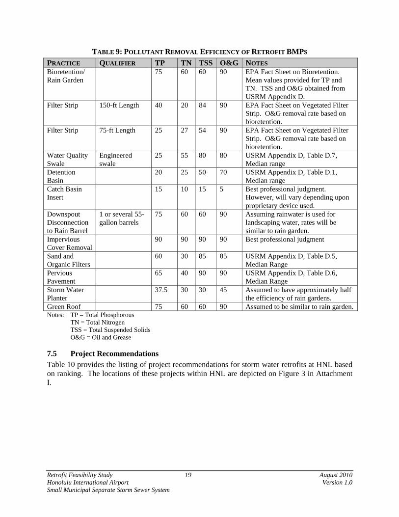
TABLE 9: POLLUTANT REMOVAL EFFICIENCY OF RETROFIT BMPS
PRACTICE QUALIFIER TP TN TSS O&G NOTES Bioretention/ Rain Garden
75 60 60 90 EPA Fact Sheet on Bioretention. Mean values provided for TP and TN. TSS and O&G obtained from USRM Appendix D.
Filter Strip 150-ft Length 40 20 84 90 EPA Fact Sheet on Vegetated Filter Strip. O&G removal rate based on bioretention.
Filter Strip 75-ft Length 25 27 54 90 EPA Fact Sheet on Vegetated Filter Strip. O&G removal rate based on bioretention.
Water Quality Swale
Engineered swale
25 55 80 80 USRM Appendix D, Table D.7, Median range
Detention Basin
20 25 50 70 USRM Appendix D, Table D.1, Median range
Catch Basin Insert
15 10 15 5 Best professional judgment. However, will vary depending upon proprietary device used.
Downspout Disconnection to Rain Barrel
1 or several 55-gallon barrels
75 60 60 90 Assuming rainwater is used for landscaping water, rates will be similar to rain garden.
Impervious Cover Removal
90 90 90 90 Best professional judgment
Sand and Organic Filters
60 30 85 85 USRM Appendix D, Table D.5, Median Range
Pervious Pavement
65 40 90 90 USRM Appendix D, Table D.6, Median Range
Storm Water Planter
37.5 30 30 45 Assumed to have approximately half the efficiency of rain gardens.
Green Roof 75 60 60 90 Assumed to be similar to rain garden. Notes: TP = Total Phosphorous TN = Total Nitrogen TSS = Total Suspended Solids O&G = Oil and Grease
7.5 Project Recommendations
Table 10 provides the listing of project recommendations for storm water retrofits at HNL based on ranking. The locations of these projects within HNL are depicted on Figure 3 in Attachment I.

Retrofit Feasibility Study 20 August 2010 Honolulu International Airport Version 1.0 Small Municipal Separate Storm Sewer System
TABLE 10: FINAL LIST OF POTENTIAL RETROFIT BMPS AT HNL
I ~ 'i ~ ~ / ~ f / / / ;~ "'-' :8 q,) 0.0
"d ;;;. "" ~ "' .s "" § 0 ~ ~ ~ iJ ~ § ~ .~ "" .2: ~
./ i! aJ 11 !I &J il 5fJ li il Rank Description ~ ~ f... ~ ~ ~ "" ~ ~ ~ ~ ~ ~ J.;. 0 Total
I Bioretention on Lagoon Drive A2-2 30 21 15 20 0 0 I 0 0 87 2 Paiea Street Bioretention E-7 30 15 15 20 0 0 I I I 83 3 Ewa Concourse Green Roof BI0-3 21 30 15 10 0 0 I I I 79 4 Overseas Terminal Green Roof DS-1 21 30 15 10 0 0 I I 0 78 5 Interisland Terminal Green Roof Bl3-2 15 30 15 10 0 0 I I I 73
New Elliot Street Parking Lot 6 Bioretention Bl5-l 30 15 15 10 I 0 I 0 I 73 7 Central Concourse Green Roof B9-l 15 30 15 10 0 0 I I 0 72 8 New J\1auka Concourse Green Roof Dl-1 15 30 15 10 0 0 I I 0 72
Rain Garden in Vacant Lot on Kalewa
9 Street Dl6-2 21 21 15 10 0 0 I 0 I 69 10 Dry Detention Basin on Kalewa Street Al-l 21 21 15 10 0 0 0 0 0 67
Bioretention at Outfall 4105 near ARFF II 2 AI0-1 15 15 15 20 0 0 0 0 I 66
Dry Detention Basin South of Runway 12 26R A2-l 30 21 15 0 0 0 0 0 0 66 13 New Hawaiian Air Hangar Green Roof Bil-l 6 30 15 10 I 0 I I I 65 14 Parking Lot R Bioretention DI0-6 21 15 15 10 0 0 I I I 64
Cell Phone Waiting Lot Permeable 15 Pavers DI0-7 6 21 15 20 0 0 0 I I 64 16 Nakolo Place Parking Lot Bioretention A4-l 6 15 15 20 0 0 I I I 59
Lagoon Drive Parking Lot Bioretnetion 17 and Permeable Pavers A9-3 15 6 15 20 0 0 I I I 59
Detention Basin from Unnamed Canal at 18 the End of Runway 4L B6-l 21 21 15 0 0 I I 0 0 59 19 Parking Lot G Bioretention DI0-4 15 15 15 10 0 0 I I I 58 20 Access "A" Canal Stabilization DI0-1 30 6 7.5 0 0 I I 0 0 45.5 21 Kaloaloa Canal Stabilization Dl4-l 30 6 7.5 0 0 I I 0 0 45.5 22 Planter for Bldg 223 Roof Runoff A3-l 6 6 15 10 0 0 I I I 40 23 Planter for Bldg 206 Roof Runoff A4-2 6 6 15 10 0 0 I I I 40 24 VIP Trans Oil Water Separator Dl6-3 6 21 0 10 0 I 0 0 0 38
Retrofit Feasibility Study 21 August 2010 Honolulu International Airport Version 1.0 Small Municipal Separate Storm Sewer System
8.0 SUMMARY
A total of 24 water quality retrofit projects have been identified and ranked as part of this feasibility study for the Honolulu International Airport. Furthermore, 65 storm drains and 8 hotspots were identified for retrofit BMPs. Secondary projects were also identified during the field reconnaissance and include repairing outfall 4747 in Basin B4, cleaning outfall 10276, and repairing channel erosion to the bridge and culvert near storm drain 5464. The purpose of this retrofit feasibility study was to identify and prioritize storm water retrofit opportunities within HNL that could assist DOTA in meeting NPDES requirements. The projects were evaluated based on the retrofit goals of reducing pollutants of concern, trapping trash and floatables, reducing runoff volumes, and providing opportunities for storm water demonstration and education. The identified retrofit opportunities have been listed based on concept design and will require further engineering study to determine their implementation potential. Additionally, concepts may need to be altered as the Airport Modernization Plan plans become finalized. Retrofit sites will be further evaluated and implemented as funds become available to the DOTA.

Retrofit Feasibility Study 22 August 2010 Honolulu International Airport Version 1.0 Small Municipal Separate Storm Sewer System
9.0 REFERENCES
Center for Watershed Protection. August 2007. Urban Storm Water Retrofit Practices Version 1.0.
The City of Charlottesville and the Center for Watershed Protection. March 2008. Charlottesville Stormwater Stewardship on Public Lands.
The City & County of Honolulu, Department of Environmental Services. May 1999. Best Management Practices Manual for Construction Sites in Honolulu.
Macdonald, G.A., A.T. Abbot, and F.L. Peterson. 1983. Volcanoes in the Sea. University of Hawaii Press.
Mink, John F. and Stephen L. Lau. February 1990. Aquifer Identification and Classification for Oahu: Groundwater Protection Strategy for Hawaii.
State of Hawaii Department of Health. June 16, 2004. 2004 List of Impaired Waters in Hawaii Prepared Under Clean Water Act 303(d).
State of Hawaii Department of Health. January 11, 2008. 2006 State of Hawaii Water Quality Monitoring and Assessment Report.
State of Hawaii, Department of Health. August 2004. Hawaii Administrative Rules, Chapters 11- 54.
State of Hawaii, Department of Health. September 2002. Hawaii Administrative Rules, Chapters 11- 55 Appendix B.
State of Hawaii, Department of Transportation, Airports Division. July 2010. Enviance System Storm Water Management Program Data.
State of Hawaii, Department of Transportation, Airports Division. July 2010. Hawaii Airports Modernization Plan, http://www.hawaiiairportsmodernization.com/3/honolulu-international-airport.
State of Hawaii, Department of Transportation, Airports Division. May 2007. Honolulu International Airport, Small Municipal Separate Storm Sewer System, Storm Water Management Program.
State of Hawaii, Department of Transportation, Airports Division. January 19 2007. National Pollutant Discharge Elimination System, Permit Number HI S000005, expires June 1, 2011.
State of Hawaii, Department of Transportation, Airports Division. April 2009. Storm Drain Outfall Inspection & Field Screening Plan.
State of Hawaii, Department of Transportation, Highways Division. March 2007. Oahu Storm Water Management Program Plan, Oahu District.
United States Environmental Protection Agency. January 9, 2008. National Pollutant Discharge Elimination System website, http://cfpub.epa.gov/npdes/stormwater/menuofbmps/index.cfm?action=browse.

Retrofit Feasibility Study 23 August 2010 Honolulu International Airport Version 1.0 Small Municipal Separate Storm Sewer System
United States Environmental Protection Agency. April 9, 2008. Webcast: The Art and Science of Stormwater Retrofitting.
U.S. Department of Agriculture Soil Conservation Service. 1972. Soil Survey of the Islands of Kauai, Oahu, Maui, Molokai, and Lanai, State of Hawaii.
U.S. Department of Interior Geological Survey. 1992. Hau’ula Quadrangle, 7.5 Minute Series (Topographic Map).

Retrofit Feasibility Study July 2010 Honolulu International Airport Version 1.0 Small Municipal Separate Storm Sewer System
ATTACHMENT I
Figures

Mamala BaySource: U.S. Geological Survey, Honolulu Quadrangle, Island of Oahu, 7.5 Minute Series, 1998
July 2010Job No. 10-6002-8
0 0.2 0.4 0.6 0.80.1MilesI 1:24,000Absolute Scale Retrofit Feasibility Study
Honolulu International Airport
Figure 1: Location Map-- EnviroServices 6 Training LLC
Center,
Honolulu International Airport
MANUWAI WATERSHED
KEEHI WATERSHED
Keehi Lagoon
Mamala Bay
0 0.3 0.6 0.9 1.20.15MilesI 1:39,000Absolute Scale
Source: Watershed data from Hawaii State Office of Planning, 1995. Aerial photograph from USDA Natural Resources Conservation Service, High Resolution Orthophoto Mosaic, Honolulu County, Southern Part Island of Oahu, 2006.
Retrofit Feasibility StudyHonolulu International Airport
Figure 2: Watershed Map
July 2010Job No. 10-6002-8

Legend Red Site ID - Hot Spot Retrofits Black Site ID - Ranked Retrofits
Ill
B 10-3 II I lZ;:
!:·[[ 1 (\/ I /"" ' I
B9-l
" 6> ~ _A
~ ~
.,.
•
1500 0 1500 3000
~--··J I I ----r.:;::;;D,P--11C SC.ALE l\1 FEET
~ ~\
+-' '--0
L_
Dl0-4
D5-l
Al0-1
E-7 Dl0-3
E-6 Dl0-6
Dl0-1
-~·
~
HONOLULU INTERNATIONAL AIRPORT
of TR~-'l +" s,. ~ 01' "' .... "' ., ; ~ Airports Division "' "' • • "' ' ;-_, .... ' rc: OF ~~~<f.
Dl0-7 E-5
E-4
-0
•
INDEX
Dl4-l E-3
Uf>it9#?~ -:- D 16-2
\S
Al-l
I
Date : July 2010
RETROFIT LOCATION MAP HONOLULU INTERNATIONAL
AIRPORT
Figure 3

Retrofit Feasibility Study July 2010 Honolulu International Airport Version 1.0 Small Municipal Separate Storm Sewer System
ATTACHMENT II
Airport Modernization Plan Rendering

2.
1.
4.
5.
C.
B.
F.
E. E. G.
3.
6.
A.
D.
H.
J.
1. New Hawaiian Airlines Air Cargo2. New Hawaiian Airlines Maintenance Facility3. New Inter-Island Maintenance Hardstands4. Widened and Straightened Taxilane G&L5. International Parking Structure6. New Consolidated Rental Car Facility
A. New Mauka ConcourseB. Existing Inter Island Terminal (IIT) (Terminal 2)C. Commuter Operations AreaD. New Ewa ConcourseE. New Frontal Gates with APM systemF. Renovated Central ConcourseG. Existing Over Sea Terminal (OST)H. New Diamond Head ConcourseJ. New Waikiki Concourse

Retrofit Feasibility Study July 2010 Honolulu International Airport Version 1.0 Small Municipal Separate Storm Sewer System
ATTACHMENT III
Storm Drain Ranking and Example Retrofit

Storm Node Ranking
Ranking EID Basin Amount of Waste Removed5 4632 A2 250 LBS. DIRT, GREEN WASTE5 4703 A6 300 LBS. DIRT5 5748 A6 150 LBS OF DIRT AND TRASH REMOVED.5 4140 B10 100 LBS. DIRT, TRASH5 5522 B9 150 LBS. OF DIRT AND TRASH REMOVED.5 4319 D10 500 LBS. DIRT5 4336 D10 150 LBS. DIRT5 4366 D10 150 LBS.5 7513 D10 150 LBS. DIRT5 10227 D10 350 LBS. DIRT, TRASH5 4580 D12 150 LBS DEBRIS5 4598 D15 200 LBS. --- DIRT, TRASH, CEMENT, BATTERY5 5147 D17 200 LBS DEBRIS5 5096 D2 400 LBS DEBRIS5 5121 D4 100 LBS. DIRT5 5123 D4 300 LBS. DIRT5 5132 D4 450 LBS. DIRT5 7466 D4 150 LBS DEBRIS5 7520 D4 500 LBS. DIRT, TRASH5 7525 D4 150 LBS. DIRT5 7465 D6 150 LBS DEBRIS5 7534 D6 300 LBS DEBRIS5 10197 D6 150 LBS. DIRT, TRASH5 10217 D6 150 LBS DEBRIS5 10255 D6 150 LBS DEBRIS5 7553 D8 100 LBS DEBRIS4 4150 B10 75 LBS. DIRT, TRASH4 4182 B10 75 LBS. DIRT4 7409 B13 75 LBS. OF DIRT REMOVED.4 5983 B9 75 LBS. DIRT4 4601 D16 75 LBS. DIRT, TRASH4 5114 D3 75 LBS DEBRIS4 5186 D7 80 LBS DEBRIS4 5212 E 75 LBS DEBRIS3 4700 A6 50 LBS. DIRT3 4702 A6 50 LBS. DIRT3 7620 B10 50 LBS. DIRT3 10161 B10 50 LBS OF DIRT AND TRASH REMOVED.3 5253 B11 50 LBS. OF DIRT REMOVED.3 4145 B9 50 LBS. DIRT3 5357 B9 50 LBS. DIRT3 5976 B9 50 LBS. DIRT3 4318 D10 40 LBS. DIRT3 4341 D10 30 LBS. DIRT3 5168 D17 50 LBS. DIRT2 5626 A2 25 LBS. DIRT, TRASH2 4623 A3 30 LBS. DIRT, TRASH2 5818 A3 25 LBS. DIRT, TRASH2 4694 A6 25 LBS. DIRT, TRASH2 4697 A6 50 LBS. DIRT2 4705 A6 30 LBS. DIRT2 5752 A6 25 LBS DEBRIS2 7692 A6 25 LBS. DIRT
Report date: July 14, 2010 Page 1 of 2

Storm Node Ranking
2 4755 A9 30 LBS. TRASH2 5678 A9 25 LBS. DIRT2 5703 A9 25 LBS. DIRT, TRASH2 4141 B10 25 LBS. DIRT, TRASH2 4142 B10 25 LBS. DIRT, TRASH2 4149 B10 25 LBS. DIRT, TRASH2 7614 B10 25 LBS. DIRT, TRASH2 5077 B12 25 LBS. OF DIRT REMOVED.2 5665 B4 25 LBS. DIRT2 5554 B9 25 LBS. DIRT2 5389 D10 25 LBS. DIRT, TRASH2 7490 D2 25 LBS. DIRT
Ranking CriteriaPounds Removed
1* ≤20 2 >20 - ≤303 >30 - ≤504 >50 - ≤1005 ≥ 100
*Not included in this report
Report date: July 14, 2010 Page 2 of 2

POI Permanent BMP Installation Report – Project No. BO1909‐23 Installed by : Hawaii Industrial Services, Ltd. 808.836.8653
Installation Date:
Pre‐Installation Photo(s):
06/22/2010
Installation Photo(s):

Retrofit Feasibility Study July 2010 Honolulu International Airport Version 1.0 Small Municipal Separate Storm Sewer System
ATTACHMENT IV
Blank Retrofit Reconnaissance Inventory (RRI) Form and Field Guide

Retrofit Reconnaissance Investigation (RRI)
Page 1 of 4 Site ID: _________
DATE: INVESTIGATOR:
WATERSHED: BASIN: SITE ID:
SITE DESCRIPTION
Name:
Address:
Land Use: DOTA Tenant Unknown
Proposed Retrofit Location:
Storage On-Site
Above Roadway Culvert Below Outfall Hotspot Operation Small Parking Lot
In Conveyance System Large Parking Lot Individual Streets Individual Rooftops
Other: Small Impervious Area Landscapes / Hardscape
Underground Other:
DRAINAGE AREA TO PROPOSED RETROFIT
Drainage Area ≈ Drainage Area Land Use:
Imperviousness ≈ % Industrial Federal / Military
Impervious Area ≈ Commercial Park
Notes: Airport Common Use Undeveloped
Vacant Other:
EXISTING STORM WATER MANAGEMENT
Existing Storm Water Practice: Yes No Possible
If Yes, Describe:
Describe Existing Site Conditions, Including Existing Site Drainage and Conveyance:
Existing Head Available and Points Where Measured:

Retrofit Reconnaissance Investigation (RRI)
Page 2 of 4 Site ID: _________
PROPOSED RETROFIT
Purpose of Retrofit: Water Quality Recharge Channel Protection Flood Control
Demonstration / Education Repair Other:
Retrofit Volume Computations – Target Storage: Retrofit Volume Computations – Available Storage:
Proposed Treatment Options: Extended Detention Dry Pond Created Wetland Bioretention
Filtering Practice Infiltration Swale Other:
Describe Elements of Proposed Retrofit, Including Surface Area, Maximum Depth of Treatment, and Conveyance:
SITE CONSTRAINTS
Adjacent Land Use: Access: Industrial Federal / Military No Constraints
Commercial Park Constrained due to:
Airport Common Use Undeveloped Slope Space
Residential Other: Utilities Tree Impacts
Possible Conflicts Due to Adjacent Land Use? Structures Tenant Activities
Yes No Airport Operations Other:
If Yes, Describe:
Conflicts with Existing Utilities: None Unknown
Potential Permitting Factors: Probable Not Probable
Yes Possible Impacts to Wetlands
Sewer Impacts to Stream / Canal
Water Impacts to Shoreline
Jet Fuel Lines Dewatering
Electric Area over 1 acre
Other: Other factors:
Soils:
Soil auger test holes: Yes No Evidence of poor infiltration (clays, fines): Yes No Evidence of shallow bedrock: Yes No Evidence of high water table (gleying, saturation): Yes No

Retrofit Reconnaissance Investigation (RRI)
Page 3 of 4 Site ID: _________
SKETCH

Retrofit Reconnaissance Investigation (RRI)
Page 4 of 4 Site ID: _________
DESIGN OR DELIVERY NOTES
FOLLOW-UP NEEDED TO COMPLETE FIELD CONCEPT
Confirm land usage Obtain existing storm water practice as-builts
Determine inclusion in modernization plan Obtain site as-builts
Confirm drainage area Obtain detailed topography
Confirm drainage area impervious cover Obtain utility mapping
Confirm volume computations Confirm storm drain invert elevations
Complete concept sketch Confirm soil types
Other:
INITIAL FEASIBILITY AND CONSTRUCTION CONSIDERATIONS
SITE CANDIDATE FOR FURTHER INVESTIGATION: YES NO MAYBE
IS SITE CANDIDATE FOR EARLY ACTION PROJECT(S): YES NO MAYBE
IF NO, SITE CANDIDATE FOR OTHER RESTORATION PROJECT(S): YES NO MAYBE
IF YES, TYPE(S):

Retrofit Reconnaissance Field Guide
THIS RRI FIELD GUIDE TEMPLATE SHOULD BE COMPLETED WITH LOCAL DATA AND ADAPTED TO MEET THE NEEDS OF LOCAL RETROFIT FIELD CREWS
UNIQUE SITE ID NOMENCLATURE GUIDANCE
Unique Site ID = Subwatershed Acronym -Sequential Number
Subwatershed Name Subwatershed Acronym Investigation Type
Basins A1 - E Retrofit Reconnaissance Investigation
Sequential Numbering begins at "1" for each subwatershed
DELINEATING DRAINAGE AREA AND ESTIMATING CURRENT IMPERVIOUS COVER
RETROFITTING OBJECTIVES
Core Retrofitting Objectives: 25% reduction in existing TP loads. Reduce runoff vol urne. Public education opportunities.
Designated Pollutant(s) of Concern: Nutrients, TSS, chlorophyll a, bacteria, oil and grease
Type of Storage Needed: 1 • 2" X impervious for on-site areas. Drainage control on a case-by-case basis.
Event Depth (inches) Water Quality Storm 1 • 2"
Minimum Water Quality Depth ("walkaway" volume) 0.6" Runoff Reduction Depth
1-year 24-hour Storm (channel protection) 2. 88.
Page 1 of 4

Retrofit Reconnaissance Field Guide
Event Depth (inches) 2-year 24-hour Storm 3.94"
1 0-year 24-hour Storm 6.63" 1 DO-year 24-hour Storm 11.05"
*Annual rainfall = 20.87" with 46 days over 0.1"
PREFERRED STORMWATER TREATMENT OPTIONS
A""" · of .,,v," I. to .;,, __ .. / ....... '··.···· . •··.· > .· .... ·.· ... · ·.···•·· \, ·'· ;··.: ..• • .: ...•... · ...•.. > \ .
;, .. '• I .• wet_,) ··'+~:;.··. .. ~:· ·" :·_ .. I • "' • ,. · ....
!<wolo•'' .6th.•( ·.• ······ .. I '· .· •> . ' .: '',. ' .. . •... ,· . · .. · .
Correct Past Mistakes • • • • ® • • ® Reduce Flood Damage • • • 0 0 ® 0 0
Education I ® ® • • • • • • Demonstration
Trap Trash & Floatables • • • ® • 0 0 0 Reduce Flows to ® 0 ® • 0 • ® • Combined Sewer
Renovate Stream ® • • • 0 ® ® 0 Corridor
Reduce Bank Erosion • ® ® ® 0 ® ® ® Support Stream Repair • ® • ® ® • ® 0
Full Watershed • • • • • • • • Restoration
KEY e = Primary stormwater treatment option to address objective ® =Secondary stormwater treatment option 0 • s, I , ,v, "o' stormwater treatment option
Comparison of Pollutant Removal Capability
•
KEY NOTES e = Excellent Removal (76 to 1 00%)
®=Good Removal (51 to 75%) 0 =Fair Removal (26 to 51%) X= Low Removal (0 to 25%)
See Profile Sheets in Chapter 2 for precise removal rates and ranges and Appendix B for documentation on derivation of removal rates
? =Unknown Removal
Page 2 of4

Retrofit Reconnaissance Field Guide
COMPUTING THE RETROFIT STORAGE VOLUME
The water quality target volume can be determined using the following equation:
Where: v, = p = Rv = DA = 12 =
V,=PI12*Rv*DA
Target storage volume (acre feet) Target rainfall depth (in inches for the 90% storm) Runoff coefficient= 0.05 + 0.009 (IC) Drainage area (acres) Conversion factor (inches to feet)
To calculate channel protection target volume, use the following equation:
Where: v, = p = IC = DA = 12 = 0.6 =
V, = Pl12 * ICI100 * DA * 0.6
Target storage volume (acre feet) 1-year 24-hour storm depth (inches) Impervious cover(%) Drainage area (acres) Conversion factor (inches to feet) Pond routing factor
COMPUTING AVAILABLE RETROFIT STORAGE
For ponds and wetlands, use the following simplified equation to estimate available storage:
Where: Vav = SA= d = 2/3 =
Vav = 213 * d *SA
Available storage at the site (acre-feet) Surface area of the facility (acres) Estimated max depth (feet) Average volume factor
For other stormwater treatment options, available storage can be estimated based on the typical surface area or depth requirements of different stormwater treatment options:
Page 3 of 4

Retrofit Reconnaissance Field Guide
MINIMUM SETBACKS
Minimum Distance ... • To Be Maintained From ...
10 feet Property Line
25 feet Building Foundation
100 feet Septic System Fields
100 feet Private Well
1,200 feet Public Water Supply Well
400 feet Surface Drinking Water Source
100 feet Surface Water
Do not submerge Sewer Line
10 feet Dry Utilities
15 feet Overhead Wires
10 feet Road (Seepage)
30 feet Highway
• Confirm that these common setbacks are consistent with local regulations
EMERGENCY CONTACT INFORMATION
Field Crew #1 cell phone: Katie Davis, 808-226-0728 Field Crew #2 cell phone:
Fire, non-emergency:
Police, non-Emergency:
Illegal dumping hotline: AIR EE 808-838-8002 Blocked storm drain inlet or pipe: AIR-EE, 808-838-8002
Erosion or drainage problems on private property:
Erosion or drainage problems on public property:
Sanitary sewer problems:
Sediment from construction site entering stream:
Septic leaks I septic tanks:
Stormwater pond safety or maintenance issue: AIR - EE, 808-838-8002 Swimming pool discharge:
Trash and debris in parks and streams:
Water main break:
*All other emergency call Airport Emergency Services, 836-6670.
Page 4 of 4

Retrofit Feasibility Study July 2010 Honolulu International Airport Version 1.0 Small Municipal Separate Storm Sewer System
ATTACHMENT V
Desktop Analysis Retrofit List
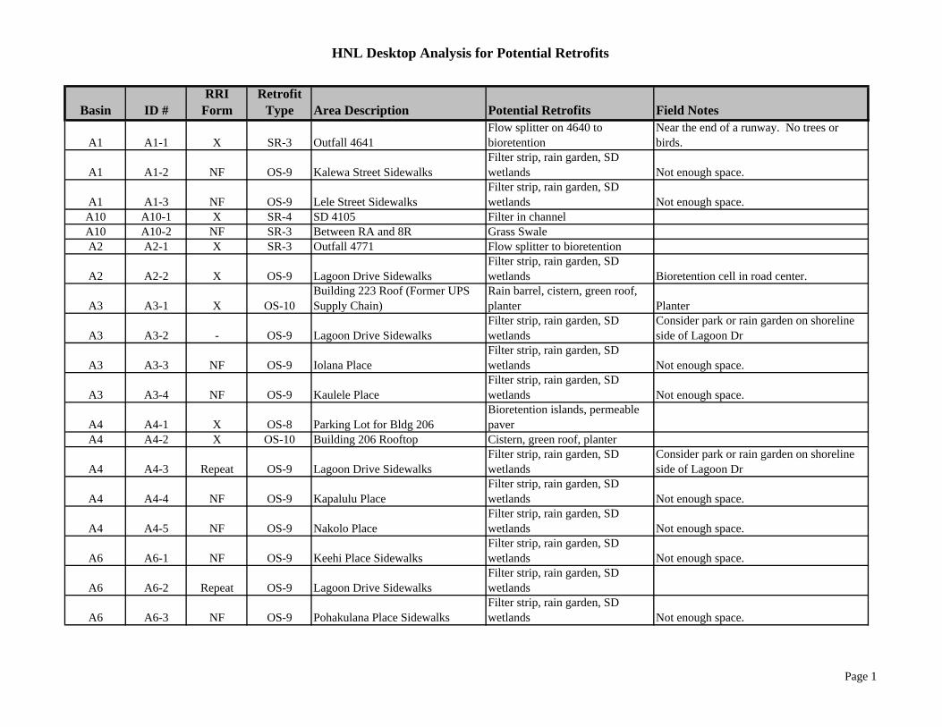
HNL Desktop Analysis for Potential Retrofits
Basin ID #RRI
FormRetrofit
Type Area Description Potential Retrofits Field Notes
A1 A1-1 X SR-3 Outfall 4641Flow splitter on 4640 to bioretention
Near the end of a runway. No trees or birds.
A1 A1-2 NF OS-9 Kalewa Street SidewalksFilter strip, rain garden, SD wetlands Not enough space.
A1 A1-3 NF OS-9 Lele Street SidewalksFilter strip, rain garden, SD wetlands Not enough space.
A10 A10-1 X SR-4 SD 4105 Filter in channelA10 A10-2 NF SR-3 Between RA and 8R Grass SwaleA2 A2-1 X SR-3 Outfall 4771 Flow splitter to bioretention
A2 A2-2 X OS-9 Lagoon Drive SidewalksFilter strip, rain garden, SD wetlands Bioretention cell in road center.
A3 A3-1 X OS-10Building 223 Roof (Former UPS Supply Chain)
Rain barrel, cistern, green roof, planter Planter
A3 A3-2 - OS-9 Lagoon Drive SidewalksFilter strip, rain garden, SD wetlands
Consider park or rain garden on shoreline side of Lagoon Dr
A3 A3-3 NF OS-9 Iolana PlaceFilter strip, rain garden, SD wetlands Not enough space.
A3 A3-4 NF OS-9 Kaulele PlaceFilter strip, rain garden, SD wetlands Not enough space.
A4 A4-1 X OS-8 Parking Lot for Bldg 206Bioretention islands, permeable paver
A4 A4-2 X OS-10 Building 206 Rooftop Cistern, green roof, planter
A4 A4-3 Repeat OS-9 Lagoon Drive SidewalksFilter strip, rain garden, SD wetlands
Consider park or rain garden on shoreline side of Lagoon Dr
A4 A4-4 NF OS-9 Kapalulu PlaceFilter strip, rain garden, SD wetlands Not enough space.
A4 A4-5 NF OS-9 Nakolo PlaceFilter strip, rain garden, SD wetlands Not enough space.
A6 A6-1 NF OS-9 Keehi Place SidewalksFilter strip, rain garden, SD wetlands Not enough space.
A6 A6-2 Repeat OS-9 Lagoon Drive SidewalksFilter strip, rain garden, SD wetlands
A6 A6-3 NF OS-9 Pohakulana Place SidewalksFilter strip, rain garden, SD wetlands Not enough space.
Page 1

HNL Desktop Analysis for Potential Retrofits
Basin ID #RRI
FormRetrofit
Type Area Description Potential Retrofits Field Notes
A6 A6-4 NF OS-9 Mokuea PlaceFilter strip, rain garden, SD wetlands Not enough space.
A7 A7-1 - OS-9 Lagoon DriveFilter strip, rain garden, SD wetlands
A8 A8-1 NF OS-9 Iako PlaceFilter strip, rain garden, SD wetlands Not enough space.
A9 A9-1 NF SR-3 Outfall 4658Flow splitter to bioretention at 4655
Head difference too great and tidally influenced.
A9 A9-2 X OS-8 Palekona Street Parking LotBioretention islands, permeable paver
A9 A9-3 NF OS-8 Lagoon Drive Parking LotBioretention islands, permeable paver Grading of parking area is an issue.
A9 A9-4 NF OS-9 Palekona StreetFilter strip, rain garden, SD wetlands Not enough space.
A9 A9-5 Repeat OS-9 Lagoon DriveFilter strip, rain garden, SD wetlands
A9 A9-6 NF OS-10 Bldg 422 Rooftop Cistern, green roof, planter Approx Roof Coverage 29,400 SFA9 A9-7 NF OS-10 Bldg 421 Rooftop Cistern, green roof, planter Approx Roof Coverage 53,150 SFA9 A9-8 NF OS-10 Bldg 420 Rooftop Cistern, green roof, planter Approx Roof Coverage 39,300 SFB10 B10-1 X OS-7 Gate 34 Triturator Containment structures
B10 B10-2 NF OS-9 Ewa Service RoadFilter strip, rain garden, SD wetlands
B10 B10-3 X OS-10 Ewa Concoure Rooftop Cistern, green roof, planterB11 B11-1 X OS-10 New Hawaiian Air Rooftop Cistern, green roof, planterB12 B12-1 NF SR-4 Elliot Street Canal In channel treatment, wet swale
B13 B13-1 NF OS-9 Elliot Street Filter strip, rain garden, SD wetlands
B13 B13-2 X OS-10 Interisland Terminal Rooftop Cistern, green roof, planter
B15 B15-1 X OS-8 New Elliot St Parking LotBioretention islands, permeable paver
B17 B17-1 - SR-4 Swale between A and 8L Enhance current BMP Swale sufficientB3 B3-1 NF SR-3 Between RA and 8R Grass Swale
B4 B4-1 NF SR-4 Canal from T-Hangars Wet swale or offline bioretention Limited by runway to westB4 B4-2 - Other Outfall 4747 Needs Repairs
Page 2

HNL Desktop Analysis for Potential Retrofits
Basin ID #RRI
FormRetrofit
Type Area Description Potential Retrofits Field Notes
B6 B6-1 X SR-4 Hickam Canal Wet swale or offline bioretention Develop current detention basin.B6 B6-2 NF Other Locate 10276 Canal on Hickam areaB6 B6-3 - OS-7 Outfall 10274 Filter Addressed with B6-1B9 B9-1 X OS-10 Central Concourse Rooftop Cistern, green roof, planterD1 D1-1 X OS-10 New Mauka Concourse Rooftop Cistern, green roof, planter
D10 D10-1 X SR-2 Culvert near SD 5466 Expand storage above culvertD10 D10-10 - Other Bridge Near 5464 Channel erosion repair Addressed with D10-1D10 D10-2 - SR-4 Access A Canal In channel treatment, wet swale Addressed with D10-1D10 D10-3 X OS-7 Gate 6 Triturator Containment structures
D10 D10-4 X OS-8 Lot G Bioretention islands, permeable paver
D10 D10-5 NF OS-8 Lot QBioretention islands, permeable paver
Bioretention area east and west of parking lot already present.
D10 D10-6 X OS-8 Lot RBioretention islands, permeable paver
D10 D10-7 X OS-8 Cell Phone Waiting LotBioretention islands, permeable paver
D10 D10-8 NF OS-9 Aolewa PlaceFilter strip, rain garden, SD wetlands Some filter strips already in place.
D10 D10-9 NF OS-10 Diamondhead Concourse Rooftop Cistern, green roof, planter Area of possible green roof space too small.D11 D11-1 NF SR-4 Kaloaloa Canal In channel treatment, wet swale Not enough space.D11 D11-2 X OS-7 Maintenance Baseyard Source Control Sweeper evap area and stockpile barrier
D11 D11-3 NF OS-8 Baseyard Parking LotBioretention islands, permeable paver Not enough space.
D13 D14-1 X SR-4 Kaloaloa Canal In channel treatment, wet swale
D15 D15-1 Repeat OS-9 Kalewa Street SidewalksFilter strip, rain garden, SD wetlands
D16 D16-1 Repeat OS-9 Kalewa Street SidewalksFilter strip, rain garden, SD wetlands
D16 D16-2 X OS-11 Vacant Lot by Pump Station Pervious paver, rain garden Determine future use
D16 D16-3 X OS-7 Vip Trans Trench to OWS at back of facilityMain goal is to prevent oils and fuels from entering canal.
Page 3

HNL Desktop Analysis for Potential Retrofits
Basin ID #RRI
FormRetrofit
Type Area Description Potential Retrofits Field Notes
D17 D17-1 - OS-9 Rodgers BlvdFilter strip, rain garden, SD wetlands
Center and perimeter bioretention already in place.
D2 D2-1 NF OS-10International Parking Structure Rooftop Cistern, green roof, planter
Not sufficent space for size of cistern required.
D2 D2-2 NF OS-9 Ala Onaona StreetFilter strip, rain garden, SD wetlands
D3 D3-1 - OS-9 Rodgers BlvdFilter strip, rain garden, SD wetlands Vegetation in place, need only conveyance
D4 D4-1 NF OS-8 Parking Lot JBioretention islands, permeable paver Grading of parking area is an issue.
D4 D4-2 NF OS-10Overseas Terminal Parking Structure (Lot D) Cistern, green roof, planter
Not sufficent space for size of cistern required.
D5 D5-1 X OS-10 Terminal Rooftop Cistern, green roof, planter Consider public demonstration
D6 D6-1 - OS-8 Employee Lot CBioretention islands, permeable paver Perimeter bioretention already in place.
D6 D6-2 - OS-8 Public Parking Lot FBioretention islands, permeable paver
Will be removed as a part of the modernization plan.
D6 D6-3 NF OS-10Overseas Terminal Parking Structure (Lot D) Cistern, green roof, planter
Not sufficent space for size of cistern required.
E E-1 X SR-4 Canal North of Aolele Street In channel treatment, wet swale May require dechannelizationE E-2 X OS-7 Bldg 180 Autobodies Source ControlE E-3 X OS-7 2875 Ualena Investment Co. Source ControlE E-4 X OS-7 Royal Hawaiian Movers Source ControlE E-5 X OS-7 Punaluu Builders Source ControlE E-6 X OS-7 So Ono Food Products Source Control
E E-7 NF OS-9 Paiea StreetFilter strip, rain garden, SD wetlands
E E-8 NF OS-9 Aolele StreetFilter strip, rain garden, SD wetlands
E E-7 X OS-9 Paiea StreetFilter strip, rain garden, SD wetlands
Page 4

Retrofit Feasibility Study July 2010 Honolulu International Airport Version 1.0 Small Municipal Separate Storm Sewer System
ATTACHMENT VI
Final Potential Retrofit List and RRI Forms

Retrofit Feasibility Study July 2010 Honolulu International Airport Version 1.0 Small Municipal Separate Storm Sewer System
ATTACHMENT VII
Hotspot RRI Forms


![Review The Search for an Alternative to [ Ga]Ga-DOTA-TATE ...thno.org/v09p1336.pdf · [68Ga]Ga-DOTA-TATE, [68Ga]Ga-DOTA-TOC, and [68Ga]Ga-DOTA-NOC allows for NET staging with high](https://static.fdocuments.in/doc/165x107/5e2a1b5b2104573c786ad22c/review-the-search-for-an-alternative-to-gaga-dota-tate-thnoorg-68gaga-dota-tate.jpg)