FDI and Growth in East Asia: Lessons for Indonesia Robert E. Lipsey ...

DP2000 Portable Dew Point Analyzer Operations Manual
Super Systems Inc. Page # 1 of 30
Model DP 2000 Portable Digital Dew Point Analyzer
OPERATIONS MANUAL
Super Systems Inc. 7205 Edington Drive
Cincinnati, OH 45249 513-772-0060
Fax: 513-772-9466 www.supersystems.com
DP2000 Portable Dew Point Analyzer Operations Manual
Super Systems Inc. Page # 2 of 30
Super Systems Inc. USA Office
Corporate Headquarters: 7205 Edington Drive Shipping Address:
7245 Edington Drive Cincinnati, OH 45249
Phone: (513) 772-0060 http://www.supersystems.com
Super Systems Europe Unit E, Tyburn Trading Estate,
Ashold Farm Road, Birmingham B24 9QG
UNITED KINGDOM Phone: +44 (0) 121 306 5180
http://www.supersystemseurope.com
Super Systems México Sistemas Superiores Integrales S de RL de CV
Calle 3 Int.: 11. Zona Ind. Benito Juarez
Querétaro, Qro. Méx. C.P.: 76120
Phone: +52 (442) 210 2459 http://www.supersystems.com.mx
Super Systems China No. 335 XianXia Road
Room 308 Shanghai, CHINA
200336 Phone: +86 21 5206 5701/2
http://www.supersystems.com
Super Systems India Pvt. Ltd. A-26 Mezzanine Floor, FIEE Complex,
Okhla Indl. Area, Phase – 2 New Delhi, India 110 020 Phone: +91 11 41050097
DP2000 Portable Dew Point Analyzer Operations Manual
Super Systems Inc. Page # 3 of 30
Contents INTRODUCTION – ..................................................................................................................................... 4 SPECIFICATIONS ...................................................................................................................................... 4 WARNINGS – ............................................................................................................................................. 5 STARTUP –................................................................................................................................................. 5 OPERATION -............................................................................................................................................. 6 INSTRUMENT DAMAGE ........................................................................................................................... 8 WHAT IS DEW POINT? ............................................................................................................................ 10 HOW IT WORKS – .................................................................................................................................... 10 MAINTENANCE / SAFETY ISSUES – ..................................................................................................... 10 FACTORY CALIBRATION – ..................................................................................................................... 11 FIELD CALIBRATION – ........................................................................................................................... 11 RECHARGING THE MODEL DP2000 – ................................................................................................... 17 TROUBLESHOOTING - ........................................................................................................................... 17 UNIT DOESN’T POWER UP: ........................................................................................................................... 17 DEW POINT READING SHOWS +80°F (OR A HIGH READING) AND NEVER DROPS: .............................................. 18 NO VISIBLE FLOW IS SHOWN IN THE FLOW METER: ........................................................................................ 23 DISPLAY APPEARS TO BE LOCKED UP AND NEVER CHANGES (NOT AT 80°F): ................................................... 24 DISPLAY READS -50°F (INDICATING THAT THE SENSOR FAILED): ................................................................... 24 DISPLAY READS HIGHER THAN NORMAL AND DOES NOT MATCH OTHER DEW POINT EQUIPMENT: ...................... 24 RETURNING THE UNIT TO SSI – ........................................................................................................... 24 WARRANTY .............................................................................................................................................. 26 SPARE PARTS – ...................................................................................................................................... 27 APPENDIX “A” – ...................................................................................................................................... 28 APPENDIX “B” – ...................................................................................................................................... 29
DP2000 Portable Dew Point Analyzer Operations Manual
Super Systems Inc. Page # 4 of 30
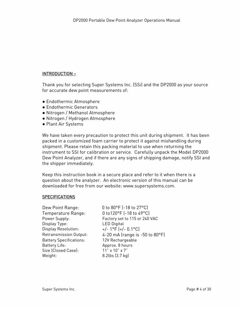
INTRODUCTION – Thank you for selecting Super Systems Inc. (SSi) and the DP2000 as your source for accurate dew point measurements of: ● Endothermic Atmosphere ● Endothermic Generators ● Nitrogen / Methanol Atmosphere ● Nitrogen / Hydrogen Atmosphere ● Plant Air Systems
We have taken every precaution to protect this unit during shipment. It has been packed in a customized foam carrier to protect it against mishandling during shipment. Please retain this packing material to use when returning the instrument to SSI for calibration or service. Carefully unpack the Model DP2000 Dew Point Analyzer, and if there are any signs of shipping damage, notify SSI and the shipper immediately. Keep this instruction book in a secure place and refer to it when there is a question about the analyzer. An electronic version of this manual can be downloaded for free from our website: www.supersystems.com. SPECIFICATIONS Dew Point Range: 0 to 80°F (-18 to 27°C) Temperature Range: 0 to120°F (-18 to 49°C) Power Supply: Factory set to 115 or 240 VAC Display Type: LED Digital Display Resolution: +/- 1°F (+/- 0.1°C) Retransmission Output: 4-20 mA (range is -50 to 80°F) Battery Specifications: 12V Rechargeable Battery Life: Approx. 8 hours Size (Closed Case): 11” x 10” x 7” Weight: 8.2lbs (3.7 kg)
DP2000 Portable Dew Point Analyzer Operations Manual
Super Systems Inc. Page # 5 of 30
WARNINGS – Although it is intended for use in an industrial environment, the DP2000 is a sensitive piece of analysis equipment. Care should be taken not to drop the analyzer or to operate it in a manner inconsistent with its intended use.
• Open all sample ports and remove all soot and/or moisture from the lines prior to attaching the sample tubing.
• The analyzer must be stored at ambient temperature (65-80°F) for at least four hours prior to operation.
• When the unit is to be returned to SSI for service or any other reason, it should be shipped in its original protective packaging. If this packaging is not available, protect the instrument with at least four inches of foam or other impact-absorbing material.
• For maximum battery life, do not charge the unit until the “battery low” indicator on the display is illuminated.
• This unit is not designed to measure the dew points in corrosive gases, such as ammonia (NH3), sulphur trioxide (SO3), chlorine (Cl), and hydrochloric acid (HCl).
• Please read and understand this Operations Manual before operating the unit.
Failure to comply with these conditions may cause damage to the unit that will not be covered under the warranty. Super Systems, Inc. is not responsible for damage to this unit caused by disregard of these warnings, neglect, or misuse. STARTUP – The DP2000 Dew Point Analyzer has been calibrated and fully charged before it was shipped from Super Systems, Inc. You can begin typical operation as soon as the unit has been allowed to stabilize in a temperature similar to the temperature in the heat-treating department. This is particularly important for units that may have been sitting overnight in a delivery van in sub-zero weather, since the rapid temperature change can cause condensation on the sensor which will cause the unit to temporarily display inaccurate readings.
DP2000 Portable Dew Point Analyzer Operations Manual
Super Systems Inc. Page # 6 of 30
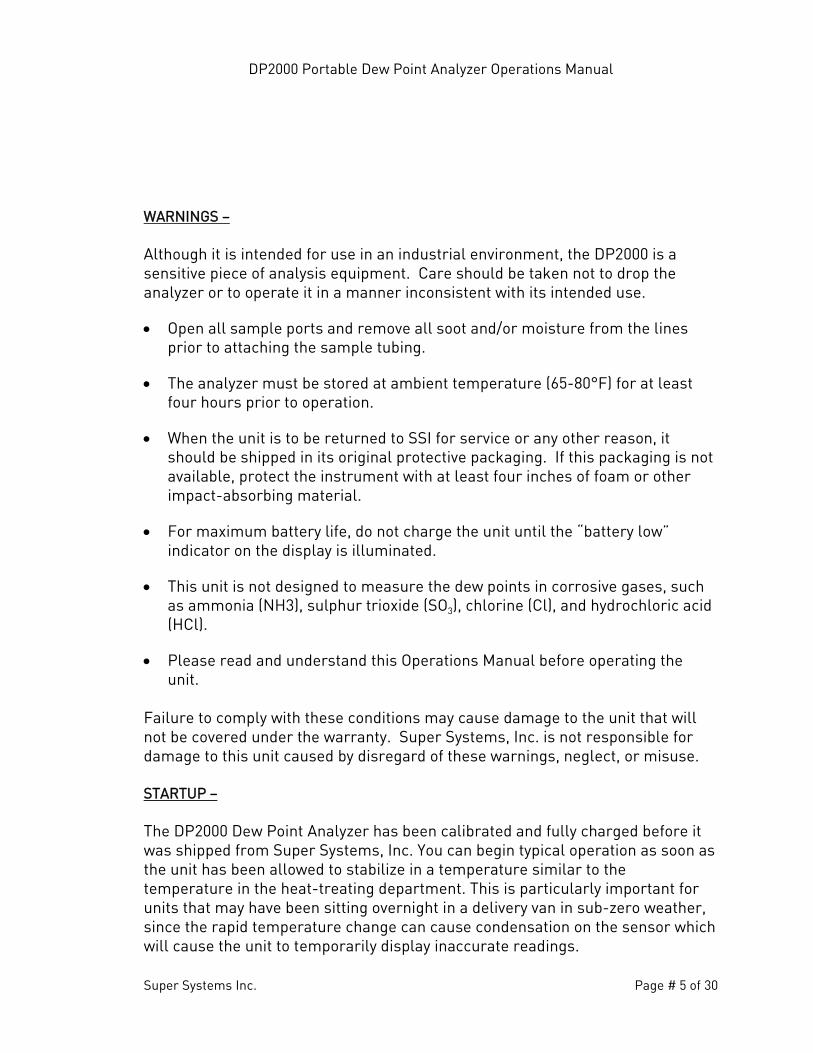
OPERATION - The use of the DP2000 is somewhat dependent upon the application. Although they are fundamentally alike, the operation procedures are different for sampling heat treating furnaces and endothermic generators. Flip the POWER switch to the on position. A green POWER ON light should illuminate indicating that the unit is turned on. The LED display should also illuminate showing “SSi” (Figure 1) followed by a dew point reading given in degrees Fahrenheit (Figure 2).
Figure 1 Figure 2
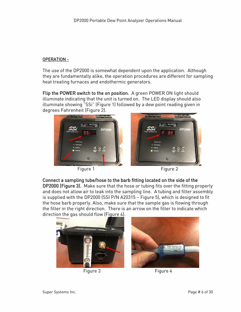
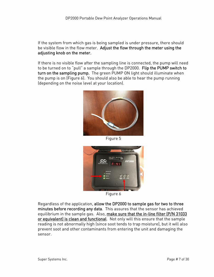
Connect a sampling tube/hose to the barb fitting located on the side of the DP2000 (Figure 3). Make sure that the hose or tubing fits over the fitting properly and does not allow air to leak into the sampling line. A tubing and filter assembly is supplied with the DP2000 (SSI P/N A20315 – Figure 5), which is designed to fit the hose barb properly. Also, make sure that the sample gas is flowing through the filter in the right direction. There is an arrow on the filter to indicate which direction the gas should flow (Figure 4).
Figure 3 Figure 4
DP2000 Portable Dew Point Analyzer Operations Manual
Super Systems Inc. Page # 7 of 30
If the system from which gas is being sampled is under pressure, there should be visible flow in the flow meter. Adjust the flow through the meter using the adjusting knob on the meter. If there is no visible flow after the sampling line is connected, the pump will need to be turned on to “pull” a sample through the DP2000. Flip the PUMP switch to turn on the sampling pump. The green PUMP ON light should illuminate when the pump is on (Figure 6). You should also be able to hear the pump running (depending on the noise level at your location).
Figure 5
Figure 6
Regardless of the application, allow the DP2000 to sample gas for two to three minutes before recording any data. This assures that the sensor has achieved equilibrium in the sample gas. Also, make sure that the in-line filter (P/N 31033 or equivalent) is clean and functional. Not only will this ensure that the sample reading is not abnormally high (since soot tends to trap moisture), but it will also prevent soot and other contaminants from entering the unit and damaging the sensor.
DP2000 Portable Dew Point Analyzer Operations Manual
Super Systems Inc. Page # 8 of 30
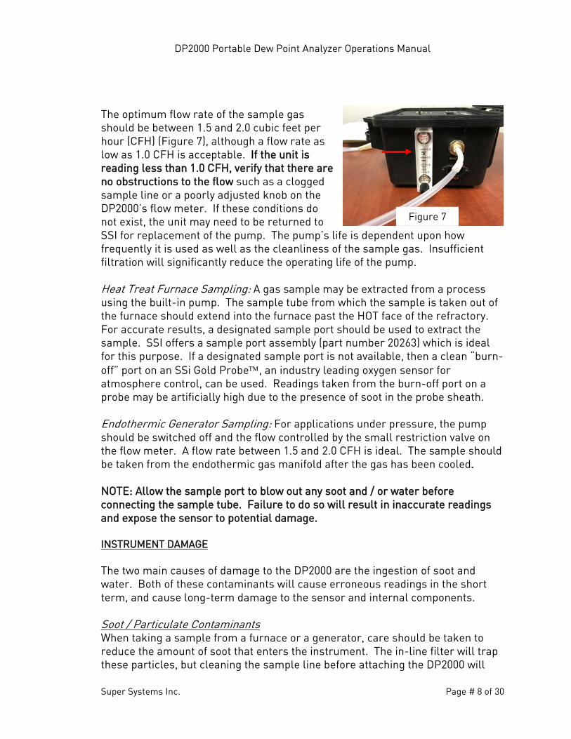
The optimum flow rate of the sample gas should be between 1.5 and 2.0 cubic feet per hour (CFH) (Figure 7), although a flow rate as low as 1.0 CFH is acceptable. If the unit is reading less than 1.0 CFH, verify that there are no obstructions to the flow such as a clogged sample line or a poorly adjusted knob on the DP2000’s flow meter. If these conditions do not exist, the unit may need to be returned to SSI for replacement of the pump. The pump’s life is dependent upon how frequently it is used as well as the cleanliness of the sample gas. Insufficient filtration will significantly reduce the operating life of the pump. Heat Treat Furnace Sampling: A gas sample may be extracted from a process using the built-in pump. The sample tube from which the sample is taken out of the furnace should extend into the furnace past the HOT face of the refractory. For accurate results, a designated sample port should be used to extract the sample. SSI offers a sample port assembly (part number 20263) which is ideal for this purpose. If a designated sample port is not available, then a clean “burn-off” port on an SSi Gold Probe, an industry leading oxygen sensor for atmosphere control, can be used. Readings taken from the burn-off port on a probe may be artificially high due to the presence of soot in the probe sheath. Endothermic Generator Sampling: For applications under pressure, the pump should be switched off and the flow controlled by the small restriction valve on the flow meter. A flow rate between 1.5 and 2.0 CFH is ideal. The sample should be taken from the endothermic gas manifold after the gas has been cooled. NOTE: Allow the sample port to blow out any soot and / or water before connecting the sample tube. Failure to do so will result in inaccurate readings and expose the sensor to potential damage. INSTRUMENT DAMAGE The two main causes of damage to the DP2000 are the ingestion of soot and water. Both of these contaminants will cause erroneous readings in the short term, and cause long-term damage to the sensor and internal components. Soot / Particulate Contaminants When taking a sample from a furnace or a generator, care should be taken to reduce the amount of soot that enters the instrument. The in-line filter will trap these particles, but cleaning the sample line before attaching the DP2000 will
Figure 7
DP2000 Portable Dew Point Analyzer Operations Manual
Super Systems Inc. Page # 9 of 30
increase the life of the filter. Furnace ports can be burned off by pumping air through them while hot, or by removing them from the heat and mechanically cleaning them. Generator ports should be opened before the instrument is attached to allow any particulate buildup to be blown out. It is also helpful to tap on the port while it is being blown out to eject any loose particles before the instrument is attached. If soot is allowed to collect on the dew point sensor in the instrument, it could result in higher readings. This soot will also retain moisture than can corrode the sensor over time. The sensor tip can be cleaned by carefully removing it from the sample block (see Section 2.3 of the Field Calibration instructions) and rinsing it in isopropyl alcohol. The power should be off while this is done, and the power should remain off for at least 30 minutes after this procedure to allow all of the alcohol to completely evaporate. Water / Moisture Contamination When a furnace or generator is being started up or cooled down, the resulting gas will contain unusually high amounts of carbon dioxide and water. When the gas cool, moisture will precipitate out and become condensation inside the sample tubing assembly. Even if the furnace or generator is operating normally, residual moisture may still be present in the sample tube or plumbing system. In the same way that the ports are checked for soot (see above) they should be checked for moisture before attaching the instrument. This is especially important when taking a sample from a generator, since the sample port is usually preceded by a significant amount of plumbing. All traces of moisture should be eliminated before attaching the instrument. Failure to do so will result in erroneous measurements and could result in damage to the analyzer. The first signs of moisture in the instrument will be visible condensation in the sample tubing and an unusually high dew point. The upper range of the sensor is +80°F (27°C), so if that value is displayed on the instrument it is probably due to the presence of moisture. If this moisture is not removed, it will cause the sensor tip to corrode and will eventually require the sensor to be replaced. To remove moisture from the instrument, the sample tubing and filter should be removed from the instrument since they will probably be wet. A dry and inert gas such as nitrogen or argon should then be flowed through the instrument (with the pump off) for as much time as it takes to dry out. This dry-out time will depend on the amount of moisture present in the instrument. The condition of the sensor can be monitored by periodically reading the dew point from the display and watching the value decrease over time. To test if it is operating properly, verify the ambient dew point against a web-based weather station that will report the ambient dew point for your area. If the displayed reading is within
DP2000 Portable Dew Point Analyzer Operations Manual
Super Systems Inc. Page # 10 of 30
three degrees (3°) of the reported dew point when the instrument is taken outside, then all of the moisture has probably been successfully removed. The wet filter and sample tubing can be re-attached after they have been completely dried out. To prevent the possibility of moisture damaging the instrument, be sure that the measured dew point is below ambient levels before it is stored. If necessary, nitrogen or argon can be used to dry out the instrument after use. WHAT IS DEW POINT? Dew point can be defined as the temperature at which the water vapor pressure of the gas equals the saturated water vapor pressure. In other words, it is the temperature at which condensation will just begin to occur as the gas is cooled. Dew point and relative humidity are not the same measurement. Relative humidity is the amount of water vapor in the air compared to the amount the air could hold if it was totally saturated, and it is expressed as a percentage, not a temperature. To determine dew point, two main variables are required: relative humidity and temperature. The DP2000 measures both variables to compute the displayed dew point. HOW IT WORKS – The dew point sensor is a “dielectric ceramic” that varies its electrical capacitance with changes in relative humidity. The sensor is mounted in a short probe, which is installed in a T-fitting that allows the sample gas to flow past the sensor. The tip of this probe contains the dielectric ceramic relative humidity (RH) sensor, as well as a built in temperature sensor to determine its dry bulb temperature. Information from both of these sensors is used to compute the resultant dew point, which is displayed on the digital LED display. MAINTENANCE / SAFETY ISSUES – One of the added features of the DP2000 is the ability to monitor the sensor’s operating temperature through the built-in thermistor in the probe tip. The temperature of the sample gas can be determined by pressing the switch labeled “Sensor Temp”. It is spring loaded, so it will automatically return to displaying dew point. Maintaining proper sensor temperature will prevent the premature failure of the sensor. The operating temperature of the sensor should remain below 140° F (60°C) at all times. Periodic checks of the sensor temperature will verify that the
DP2000 Portable Dew Point Analyzer Operations Manual
Super Systems Inc. Page # 11 of 30
sensor is not being exposed to excessive heat. If these periodic checks show a high sensor temperature, then the length of sample tubing should be increased to allow for adequate cooling of the sample before it passes the sensor tip. Continuous operation of the DP2000 Dew Point Analyzer will lead to premature failure, since many the internal components are not designed for uninterrupted use. If continuous monitoring of Dew Points is required, please contact Super Systems, Inc. at (800) 666-4330 to inquire about products intended specifically for this application. FACTORY CALIBRATION – Factory calibration is recommended every six months if the unit is used regularly. SSI’s calibration is NIST traceable and includes a numbered “Certificate of Calibration”. This certificate also indicates the accuracy of the analyzer before and after calibration. Please contact Super Systems, Inc. at (800) 666-4330 for more information regarding this service. FIELD CALIBRATION – It is also possible to calibrate the DP2000 in the field, which will require the optional calibration kit (Part Number 31030). The instructions for a field calibration are shown here, however please feel free to contact Super Systems at 800-666-4330 if you would like to review the process with us before you begin. The calibration kit consists of two bottles of saturated salt solution in which each bottle generates a precise relative humidity percentage (R.H. %) value. One bottle is 11.3% R.H., and the other is 75.3% R.H. These two specific calibration points are already pre-programmed into the microprocessor board. 1.0 Open the unit
1.1 Remove the aluminum faceplate of the DP2000 by removing the single allen-head cap screw located at the bottom front of the faceplate. After the screw has been removed, carefully lift the front of the faceplate and slide it towards you about an inch. After the faceplate has been removed, it can temporarily be rested in the lid of the open case, to allow access to the components inside. This plate will still be connected to the interior circuit boards, so care should be taken to maintain all existing connections.
2.0 Locate the key components within the unit
DP2000 Portable Dew Point Analyzer Operations Manual
Super Systems Inc. Page # 12 of 30
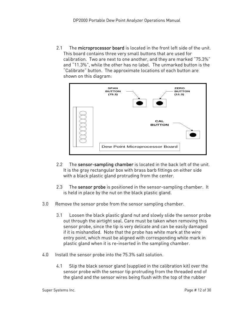
2.1 The microprocessor board is located in the front left side of the unit. This board contains three very small buttons that are used for calibration. Two are next to one another, and they are marked “75.3%” and “11.3%”, while the other has no label. The unmarked button is the “Calibrate” button. The approximate locations of each button are shown on this diagram:
2.2 The sensor-sampling chamber is located in the back left of the unit.
It is the gray rectangular box with brass barb fittings on either side with a black plastic gland protruding from the center.
2.3 The sensor probe is positioned in the sensor-sampling chamber. It
is held in place by the nut on the black plastic gland. 3.0 Remove the sensor probe from the sensor sampling chamber.
3.1 Loosen the black plastic gland nut and slowly slide the sensor probe out through the airtight seal. Care must be taken when removing this sensor probe, since the tip is very delicate and can be easily damaged if it is mishandled. Note that the probe has white mark at the wire entry point, which must be aligned with corresponding white mark in plastic gland when it is re-inserted in the sampling chamber.
4.0 Install the sensor probe into the 75.3% salt solution.
4.1 Slip the black sensor gland (supplied in the calibration kit) over the sensor probe with the sensor tip protruding from the threaded end of the gland and the sensor wires being flush with the top of the rubber
SPANBUTTON
(75.3)
ZEROBUTTON(11.3)
CALBUTTON
Dew Point Microprocessor Board
DP2000 Portable Dew Point Analyzer Operations Manual
Super Systems Inc. Page # 13 of 30
o-ring in the gland. Tighten the gland around the sensor. This does not need to be done with a wrench or other tools, but it does need to be tight enough to prevent ambient air from contaminating the humidity level of the sampling chamber.
4.2 Remove the cap of the 75.3% salt solution and install the sensor
gland (with the sensor) into the salt solution. To increase the life of the calibration salts, an effort should be made to minimize the amount of time that the salt solution is exposed to the ambient air.
5.0 Allow the sensor to reach equilibrium with the calibration salt.
5.1 With the power to the unit still turned off, leave the sensor in the calibration salt for a minimum of eighteen (18) hours. It is acceptable to leave the sensor in the salt solution for a longer period of time, even a few days, if desired.
6.0 Begin the 75.3% (Span) calibration process.
6.1 After leaving the sensor in the salt for at least eighteen (18) hours, turn the unit on. The reading on the display is not important at this point.
6.2 Simultaneously press the “75.3%” and “Calibration” buttons on the
microprocessor board. 7.0 Verify the 75.3% (Span) calibration.
7.1 Do not be concerned if the unit does not display 75.3, since it is not supposed to match the value of the calibration salt.
7.2 Use the “Sensor Temp” switch on the faceplate of the unit to
determine and record the sensor temperature.
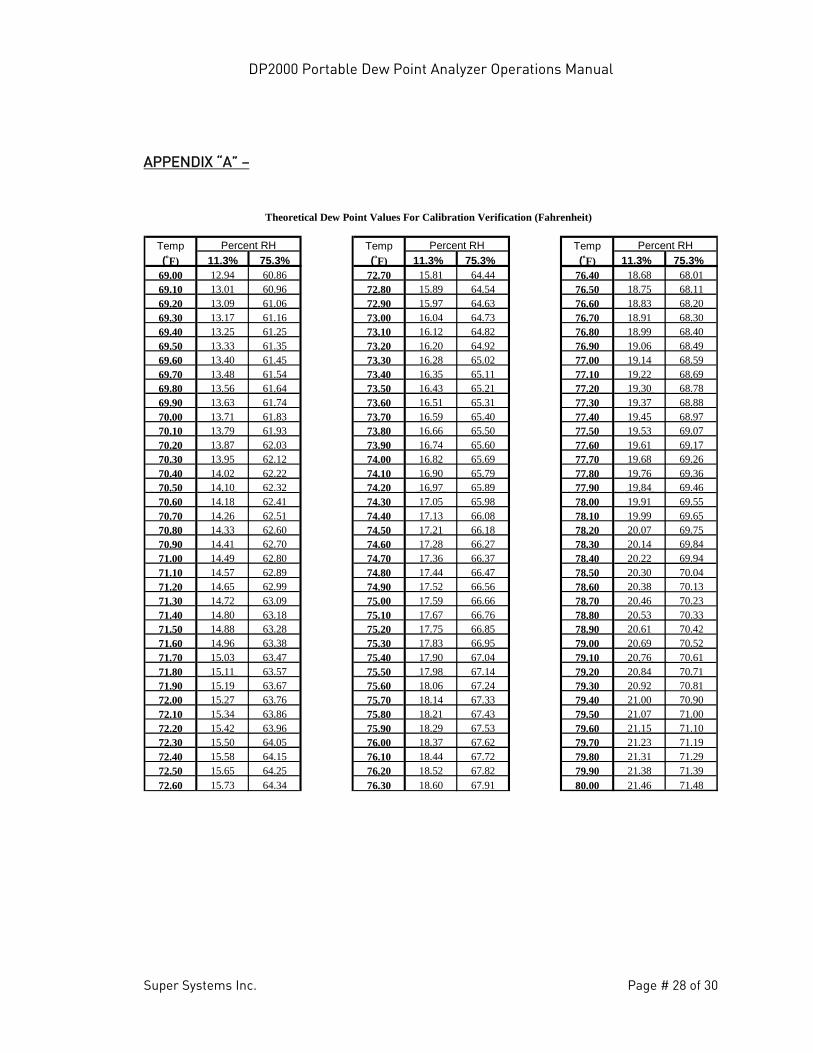
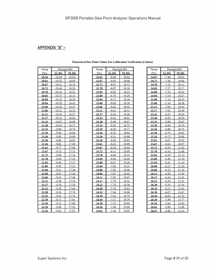
7.3 Look up this temperature on the “Theoretical Dew Point Values for Calibration Verification” chart located in the back of this manual. Appendix “A” will show the temperature values in Fahrenheit, and Appendix B will show the temperature values in Celsius.
7.4 Next to the appropriate temperature, note the number in the
corresponding column titled “75.3%”. This should match with the dew point that is shown on the display of the DP2000.
DP2000 Portable Dew Point Analyzer Operations Manual
Super Systems Inc. Page # 14 of 30
8.0 Determine the acceptability of the reading.
8.1 The value printed on the chart in Appendix A is a theoretical value, and some variation can be expected. When a calibration is performed at SSI, we certify (in writing) that the unit displays within +/- 1 degree of the theoretical value after it has been calibrated. We would not consider a calibration to be successful unless it is within +/- 1 degree, however in the case of a field calibration, this degree of accuracy may or may not be required. The degree of accuracy that is acceptable is determined by the policy of the person performing the calibration.
NOTE: Keep in mind that the DP2000 only displays even numbers, and not tenths of a degree. Therefore, a reading of 65°F could be as low as 64.50 or as high as 65.49.
9.0 Allow the sensor to achieve equilibrium at ambient atmosphere.
9.1 After the 75.3% (Span) calibration has been completed, remove the sensor from the calibration salt and replace the cap on the salt.
9.2 Leave the sensor probe in the gland and while the unit is still on,
allow it to achieve equilibrium at the ambient atmosphere in the room. This is accomplished by simply leaving the sensor exposed to ambient air for between two and three minutes. You will know when this has been accomplished when the numbers on the display begin to stabilize.
10.0 Install the sensor probe into the 11.3% salt solution.
10.1 Remove the cap of the 11.3% salt solution and install the sensor gland (with the sensor) into the salt solution. To increase the life of the calibration salts, an effort should be made to minimize the amount of time that the salt solution is exposed to the ambient air.
10.2 Turn the unit off.
11.0 Allow the sensor to reach equilibrium with the calibration salt.
11.1 With the power to the unit still turned off, leave the sensor in the calibration salt for a minimum of 24 hours. It is acceptable to leave the sensor in the salt solution for a longer period of time, even a few days, if desired.
DP2000 Portable Dew Point Analyzer Operations Manual
Super Systems Inc. Page # 15 of 30
12.0 Begin the 11.3% (Zero) calibration process
12.1 After leaving the sensor in the salt for at least twenty-four (24) hours, turn the unit on. The reading on the display is not important at this point.
12.2 Simultaneously press the “11.3%” and “Calibration” buttons on the
microprocessor board. 13.0 Verify the 11.3% (Zero) calibration
13.1 Do not be concerned if the unit does not display 11.3, since it is not supposed to match the value of the calibration salt.
13.2 Use the “Sensor Temp” switch on the faceplate of the unit to
determine and record the sensor temperature.
13.3 Look up this temperature on the “Theoretical Dew Point Values for Calibration Verification” chart located in the back of this manual. Appendix “A” will show the temperature values in Fahrenheit, and Appendix B will show the temperature values in Celsius.
13.4 Next to the appropriate temperature, note the number in the
corresponding column titled “11.3%”. This should match with the dew point that is shown on the display of the DP2000.
14.0 Determine the acceptability of the reading
14.1 The value printed on the chart in Appendix A is a theoretical value, and some variation can be expected. When a calibration is performed at SSI, we certify (in writing) that the unit displays within +/- 1 degree of the theoretical value after it has been calibrated. We would not consider a calibration to be successful unless it is within +/- 1 degree, however in the case of a field calibration, this degree of accuracy may or may not be required. The degree of accuracy that is acceptable is determined by the policy of the person performing the calibration.
NOTE: Keep in mind that the DP2000 only displays even numbers, and not tenths of a degree. Therefore, a reading of 18°F (-7.8°C) could be as low as 17.50°F (-8.06°C) or as high as 18.49°F (-7.51°C).
DP2000 Portable Dew Point Analyzer Operations Manual
Super Systems Inc. Page # 16 of 30
15.0 Allow the sensor to achieve equilibrium at ambient atmosphere
15.1 After the 11.3% (Zero) calibration has been completed, remove the sensor from the calibration salt and replace the cap.
15.2 Leave the sensor probe in the gland and while the unit is still on,
allow it to achieve equilibrium at the ambient atmosphere in the room. This should take between two and three minutes. You will know when this has been accomplished when the numbers on the display begin to stabilize.
16.0 Re-assemble the unit
16.1 After the calibration process has been completed, remove the sensor probe from the gland and return it to the sensor-sampling chamber, taking care to position it properly. The white mark on the sensor probe should face towards the right of the sensor-sampling chamber (at 3:00 if it were the face of a clock.). If the white mark is not visible, then it should be placed so the sample flow directly strikes the face of the mirror on the sensor tip (the sample flows from right-to-left). In other words, the mirror should face the incoming gas stream.
16.2 Hand-tighten the black sensor gland to prevent air from leaking out
of the sampling chamber.
16.3 Slide the faceplate into position with the back posts going into the corresponding holes as the faceplate slides back.
16.4 Verify that the system is leak proof by turning on the pump and
placing a finger over the sample inlet port. The flow meter on the side of the unit will drop to zero if there are no leaks. If a leak is detected, make sure that all tubing connections are tight, especially the black sensor gland.
16.5 After the unit has passed the leak test, re-fasten the screw into the
faceplate and tighten it. 17.0 Make sure that all caps are replaced on the calibration salts, and return
the DP2000 to service.
DP2000 Portable Dew Point Analyzer Operations Manual
Super Systems Inc. Page # 17 of 30
RECHARGING THE MODEL DP2000 – The internal 12V gel cell battery has enough power to run the analyzer for approximately 8 hours, although after many charge/discharge cycles some loss of battery life can be expected. When it is time to recharge the unit, a red “Battery Low” light will illuminate. When this light comes on, the unit will operate for an additional one to two hours before the battery is unable to power the unit and it shuts off. A full recharge will take 16 hours, however the analyzer can be used while it is recharging. It can also be left on charge for as long as you want, with no harm to the battery. A green “Recharging” light will come on to verify that the unit is charging, and this light will go out automatically when it is completely charged. For maximum battery life, it is recommended that the battery be discharged before it is recharged. The battery does not need to be completely discharged however, there is a correlation between the number of times that a battery is charged and the life span of the battery. By keeping the number of times the battery is recharged to a minimum, the battery life can be increased. To charge the analyzer, plug the power cord into any 110 VAC outlet. The instrument is not intended for use with 220 VAC power unless it has been specifically set up accordingly at the factory. If this has been done, the serial number plate will indicate 220 VAC operation. TROUBLESHOOTING - Unit doesn’t power up: Verify that the battery has been charged. See RECHARGING THE MODEL DP2000 section to make sure that the battery has been charged according to instruction. If the unit has been charged, but still won’t power up, attempt to power up the unit with the power cord connected to a 110 VAC outlet. If the unit will power up only when the power cord is plugged in, the battery may be bad. Please contact Super Systems, Inc. at (800) 666-4330 for more information regarding the replacement of the battery. Verify that the unit has power. Verify that the unit has been charged properly. Connect the power cord and plug it into a 110 VAC outlet. If the unit still will not power up with the power cord is plugged in, there may be significant damage to
DP2000 Portable Dew Point Analyzer Operations Manual
Super Systems Inc. Page # 18 of 30
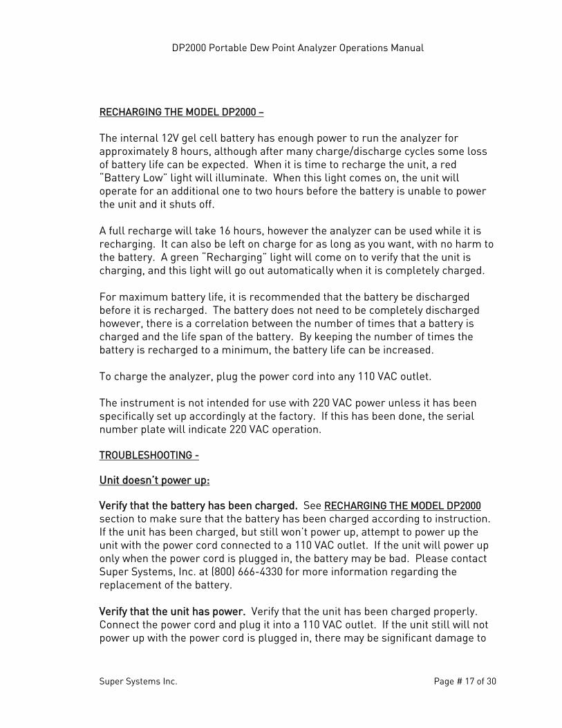
the unit. Please contact Super Systems, Inc. at (800) 666-4330 for more information regarding this issue. Dew point reading shows +80°F (or a high reading) and never drops: The upper range of the sensor is +80°F (27°C). If that value is displayed, it likely indicates the presence of moisture in the sample tubing or on the dew point sensor tip. If this moisture is not removed, it will cause the sensor tip to corrode and will eventually require the sensor to be replaced. First, check the dew point sensor tip for obvious signs of moisture, corrosion, and/or damage causing high readings. Remove power from the DP2000. Make sure that it is not plugged into a power source and that the POWER switch is off. Open the case by loosening the Allen head screw located in the bottom of the face plate (Figure 8). Loosening this screw requires a 1/8” Allen wrench. Lift up the face plate, but be careful of the wires connecting the face plate to the case (Figure 9).
Figure 8 Figure 9
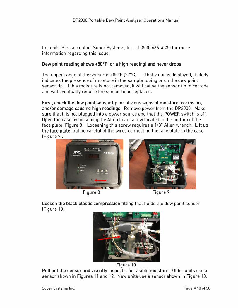
Loosen the black plastic compression fitting that holds the dew point sensor (Figure 10).
Figure 10
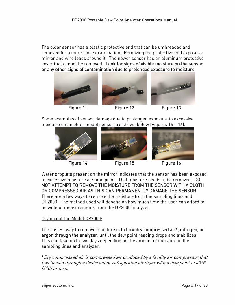
Pull out the sensor and visually inspect it for visible moisture. Older units use a sensor shown in Figures 11 and 12. New units use a sensor shown in Figure 13.
DP2000 Portable Dew Point Analyzer Operations Manual
Super Systems Inc. Page # 19 of 30
The older sensor has a plastic protective end that can be unthreaded and removed for a more close examination. Removing the protective end exposes a mirror and wire leads around it. The newer sensor has an aluminum protective cover that cannot be removed. Look for signs of visible moisture on the sensor or any other signs of contamination due to prolonged exposure to moisture.
Figure 11 Figure 12 Figure 13
Some examples of sensor damage due to prolonged exposure to excessive moisture on an older model sensor are shown below (Figures 14 – 16).
Figure 14 Figure 15 Figure 16
Water droplets present on the mirror indicates that the sensor has been exposed to excessive moisture at some point. That moisture needs to be removed. DO NOT ATTEMPT TO REMOVE THE MOISTURE FROM THE SENSOR WITH A CLOTH OR COMPRESSED AIR AS THIS CAN PERMANENTLY DAMAGE THE SENSOR. There are a few ways to remove the moisture from the sampling lines and DP2000. The method used will depend on how much time the user can afford to be without measurements from the DP2000 analyzer. Drying out the Model DP2000: The easiest way to remove moisture is to flow dry compressed air*, nitrogen, or argon through the analyzer, until the dew point reading drops and stabilizes. This can take up to two days depending on the amount of moisture in the sampling lines and analyzer. *Dry compressed air is compressed air produced by a facility air compressor that has flowed through a desiccant or refrigerated air dryer with a dew point of 40°F (4°C) or less.
DP2000 Portable Dew Point Analyzer Operations Manual
Super Systems Inc. Page # 20 of 30
The in-line filter is the first place where moisture tends to collect. Upon examination, there may not be any visible moisture in the filter element, but there may still be a significant amount of moisture in the element. Remove the in-line filter and replace it. This will help reduce the time required to dry out the DP2000. With the filter element replaced, test the DP2000 to see if it is operating properly. Verify the ambient dew point against a web-based weather station that will report the ambient dew point for your area. If the displayed reading is within three degrees (3°) of the reported dew point when the instrument is taken outside, then all of the moisture has probably been successfully removed. The wet filter and sample tubing can be re-attached after they have been completely dried out. The filter element will regain all of its original filtering properties after it has dried out. Option 1: Connect a dry gas source to the sampling line of the DP2000. Verify that the pressure is low (less than 2 psi) to prevent damage to the dew point sensor. Adjust flow through the DP2000 to 1.5 to 2 CFH of flow indicated by the flow meter on the side of the DP2000. Allow gas to flow through the unit and monitor the dew point reading from the sensor. As the sample line and sensor dry out, the dew point reading should drop and stabilize. Option 2: Moisture can be removed from the sampling line much more quickly if the lines are disconnected and blown out with dry compressed air, nitrogen, or argon. Below are steps to remove moisture with that method. Isolate the sampling line from the atmosphere gas source to the DP2000 sample inlet by disconnecting it on both ends. Higher pressures can be used for this process as long as the lines have been disconnected at both ends and no sensing equipment or filters are exposed to the high pressure gas. Blow gas through the sampling line for as long as it takes to remove any visible moisture from the line. Reconnect the line at both ends. Lift the face plate of the DP2000 (reference Figure 8 & 9) and disconnect the tubing between where the sample gas enters the unit and the Sensor Sampling Block. Blow gas through the sampling line for as long as it takes to remove any visible moisture from the line. Reconnect the tubing at both ends.
DP2000 Portable Dew Point Analyzer Operations Manual
Super Systems Inc. Page # 21 of 30
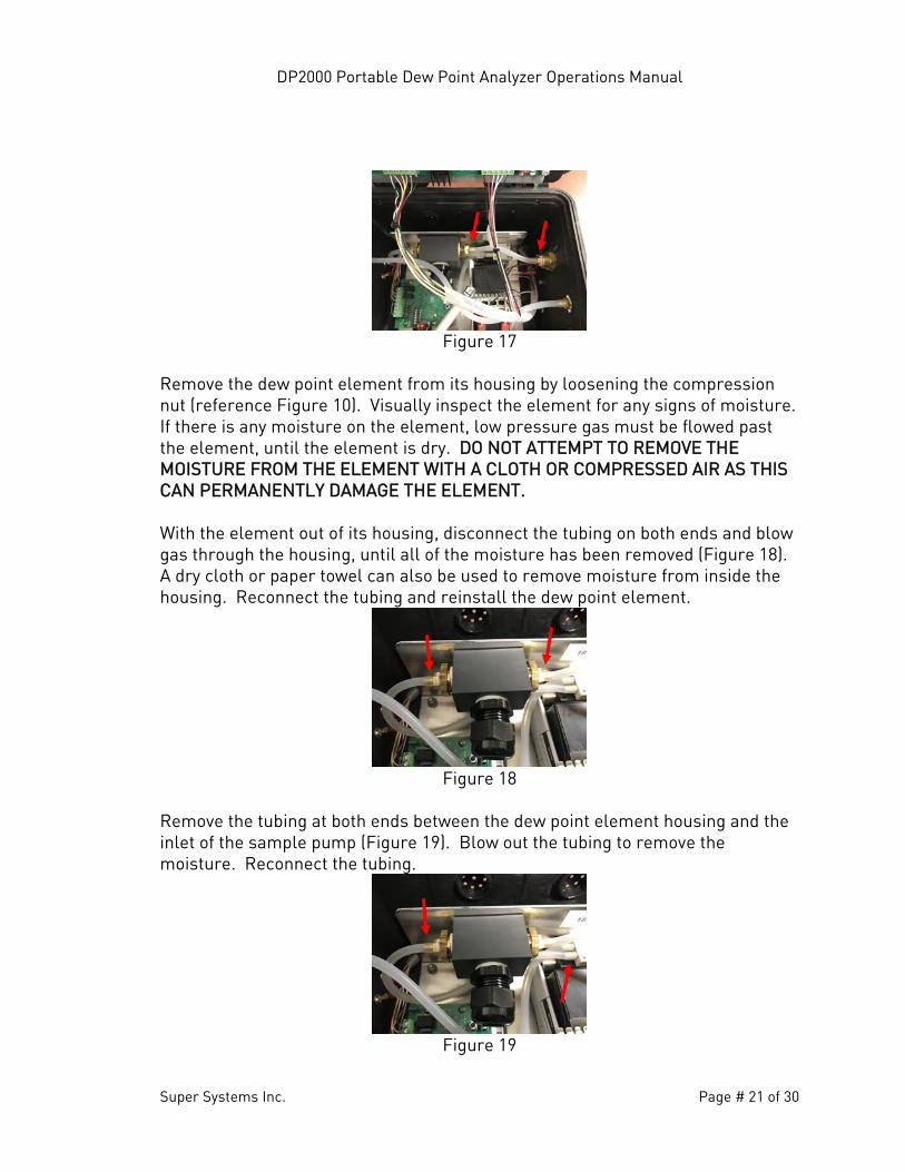
Figure 17
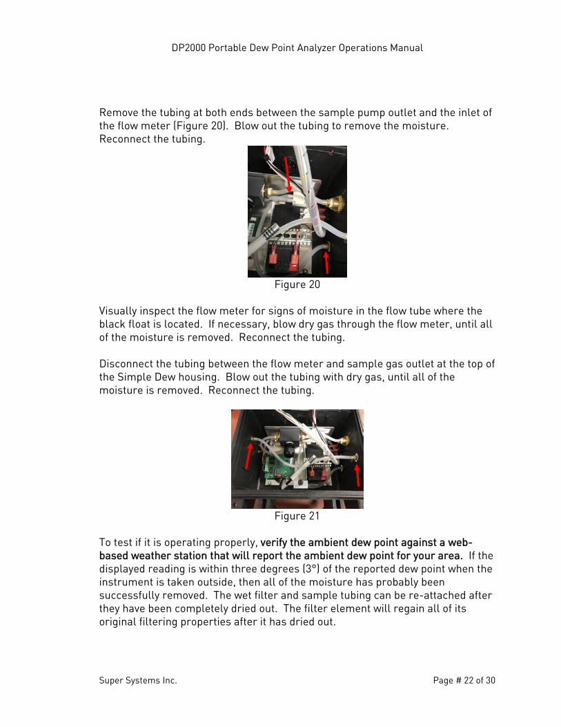
Remove the dew point element from its housing by loosening the compression nut (reference Figure 10). Visually inspect the element for any signs of moisture. If there is any moisture on the element, low pressure gas must be flowed past the element, until the element is dry. DO NOT ATTEMPT TO REMOVE THE MOISTURE FROM THE ELEMENT WITH A CLOTH OR COMPRESSED AIR AS THIS CAN PERMANENTLY DAMAGE THE ELEMENT. With the element out of its housing, disconnect the tubing on both ends and blow gas through the housing, until all of the moisture has been removed (Figure 18). A dry cloth or paper towel can also be used to remove moisture from inside the housing. Reconnect the tubing and reinstall the dew point element.
Figure 18
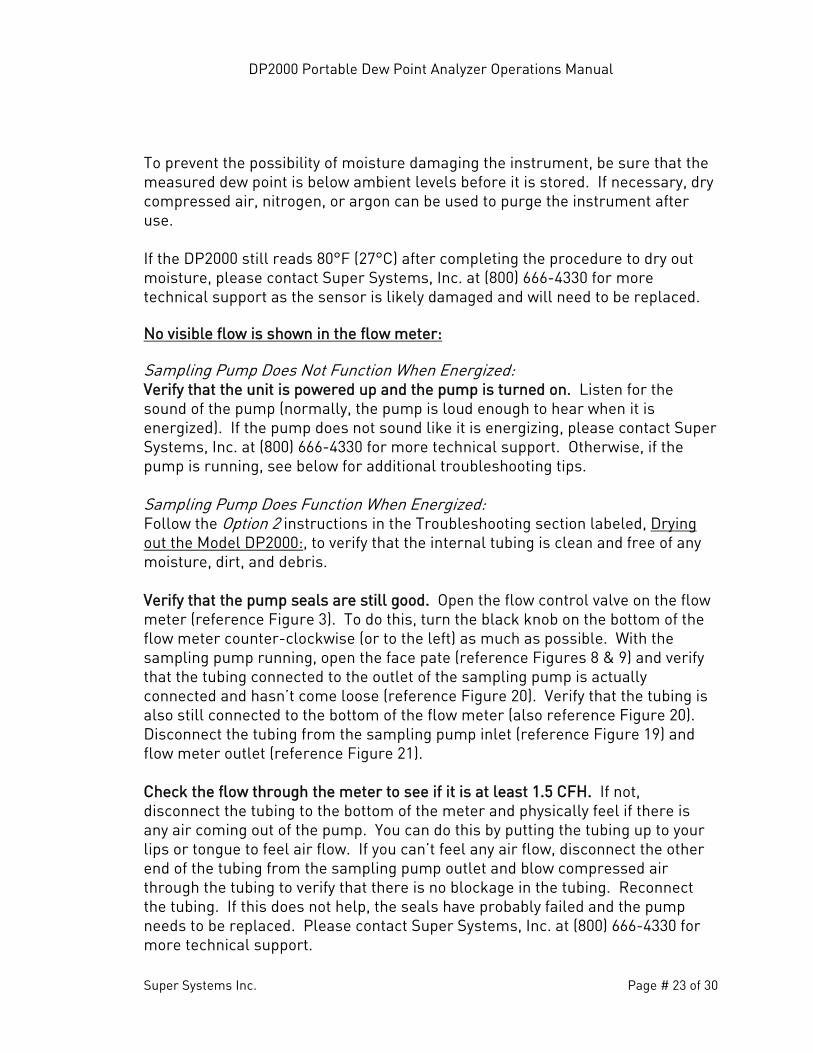
Remove the tubing at both ends between the dew point element housing and the inlet of the sample pump (Figure 19). Blow out the tubing to remove the moisture. Reconnect the tubing.
Figure 19
DP2000 Portable Dew Point Analyzer Operations Manual
Super Systems Inc. Page # 22 of 30
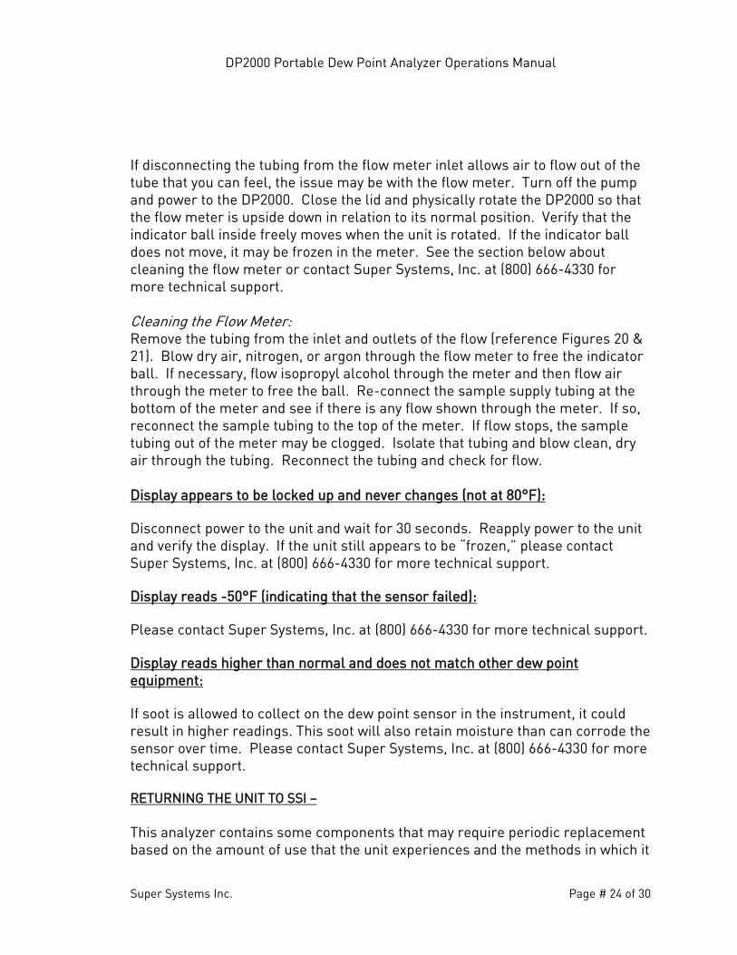
Remove the tubing at both ends between the sample pump outlet and the inlet of the flow meter (Figure 20). Blow out the tubing to remove the moisture. Reconnect the tubing.
Figure 20
Visually inspect the flow meter for signs of moisture in the flow tube where the black float is located. If necessary, blow dry gas through the flow meter, until all of the moisture is removed. Reconnect the tubing.
Disconnect the tubing between the flow meter and sample gas outlet at the top of the Simple Dew housing. Blow out the tubing with dry gas, until all of the moisture is removed. Reconnect the tubing.
Figure 21
To test if it is operating properly, verify the ambient dew point against a web-based weather station that will report the ambient dew point for your area. If the displayed reading is within three degrees (3°) of the reported dew point when the instrument is taken outside, then all of the moisture has probably been successfully removed. The wet filter and sample tubing can be re-attached after they have been completely dried out. The filter element will regain all of its original filtering properties after it has dried out.
DP2000 Portable Dew Point Analyzer Operations Manual
Super Systems Inc. Page # 23 of 30
To prevent the possibility of moisture damaging the instrument, be sure that the measured dew point is below ambient levels before it is stored. If necessary, dry compressed air, nitrogen, or argon can be used to purge the instrument after use. If the DP2000 still reads 80°F (27°C) after completing the procedure to dry out moisture, please contact Super Systems, Inc. at (800) 666-4330 for more technical support as the sensor is likely damaged and will need to be replaced. No visible flow is shown in the flow meter: Sampling Pump Does Not Function When Energized: Verify that the unit is powered up and the pump is turned on. Listen for the sound of the pump (normally, the pump is loud enough to hear when it is energized). If the pump does not sound like it is energizing, please contact Super Systems, Inc. at (800) 666-4330 for more technical support. Otherwise, if the pump is running, see below for additional troubleshooting tips. Sampling Pump Does Function When Energized: Follow the Option 2 instructions in the Troubleshooting section labeled, Drying out the Model DP2000:, to verify that the internal tubing is clean and free of any moisture, dirt, and debris. Verify that the pump seals are still good. Open the flow control valve on the flow meter (reference Figure 3). To do this, turn the black knob on the bottom of the flow meter counter-clockwise (or to the left) as much as possible. With the sampling pump running, open the face pate (reference Figures 8 & 9) and verify that the tubing connected to the outlet of the sampling pump is actually connected and hasn’t come loose (reference Figure 20). Verify that the tubing is also still connected to the bottom of the flow meter (also reference Figure 20). Disconnect the tubing from the sampling pump inlet (reference Figure 19) and flow meter outlet (reference Figure 21). Check the flow through the meter to see if it is at least 1.5 CFH. If not, disconnect the tubing to the bottom of the meter and physically feel if there is any air coming out of the pump. You can do this by putting the tubing up to your lips or tongue to feel air flow. If you can’t feel any air flow, disconnect the other end of the tubing from the sampling pump outlet and blow compressed air through the tubing to verify that there is no blockage in the tubing. Reconnect the tubing. If this does not help, the seals have probably failed and the pump needs to be replaced. Please contact Super Systems, Inc. at (800) 666-4330 for more technical support.
DP2000 Portable Dew Point Analyzer Operations Manual
Super Systems Inc. Page # 24 of 30
If disconnecting the tubing from the flow meter inlet allows air to flow out of the tube that you can feel, the issue may be with the flow meter. Turn off the pump and power to the DP2000. Close the lid and physically rotate the DP2000 so that the flow meter is upside down in relation to its normal position. Verify that the indicator ball inside freely moves when the unit is rotated. If the indicator ball does not move, it may be frozen in the meter. See the section below about cleaning the flow meter or contact Super Systems, Inc. at (800) 666-4330 for more technical support. Cleaning the Flow Meter: Remove the tubing from the inlet and outlets of the flow (reference Figures 20 & 21). Blow dry air, nitrogen, or argon through the flow meter to free the indicator ball. If necessary, flow isopropyl alcohol through the meter and then flow air through the meter to free the ball. Re-connect the sample supply tubing at the bottom of the meter and see if there is any flow shown through the meter. If so, reconnect the sample tubing to the top of the meter. If flow stops, the sample tubing out of the meter may be clogged. Isolate that tubing and blow clean, dry air through the tubing. Reconnect the tubing and check for flow.
Display appears to be locked up and never changes (not at 80°F): Disconnect power to the unit and wait for 30 seconds. Reapply power to the unit and verify the display. If the unit still appears to be “frozen,” please contact Super Systems, Inc. at (800) 666-4330 for more technical support. Display reads -50°F (indicating that the sensor failed): Please contact Super Systems, Inc. at (800) 666-4330 for more technical support. Display reads higher than normal and does not match other dew point equipment: If soot is allowed to collect on the dew point sensor in the instrument, it could result in higher readings. This soot will also retain moisture than can corrode the sensor over time. Please contact Super Systems, Inc. at (800) 666-4330 for more technical support. RETURNING THE UNIT TO SSI – This analyzer contains some components that may require periodic replacement based on the amount of use that the unit experiences and the methods in which it
DP2000 Portable Dew Point Analyzer Operations Manual
Super Systems Inc. Page # 25 of 30
is used. If service on the unit is necessary, it should be sent back to Super Systems, Inc. in the original packaging for repair. If the original packaging is not available, the analyzer should be surrounded by impact-absorbing materials and placed in a box. It is the responsibility of the shipper to ensure that the DP2000 arrives at SSI undamaged. Before shipping the analyzer, please call (800) 666-4330 to receive a Return Materials Authorization (RMA) number. The shipping address that should be used for returns is:
Super Systems, Inc. ATTN: RMA #XXXX
7245 Edington Drive Cincinnati, OH 45249
DP2000 Portable Dew Point Analyzer Operations Manual
Super Systems Inc. Page # 26 of 30
WARRANTY Limited Warranty for Super Systems Products: The Limited Warranty applies to new Super Systems Inc. (SSI) products purchased direct from SSI or from an authorized SSI dealer by the original purchaser for normal use. SSI warrants that a covered product is free from defects in materials and workmanship, with the exceptions stated below. The limited warranty does not cover damage resulting from commercial use, misuse, accident, modification or alteration to hardware or software, tampering, unsuitable physical or operating environment beyond product specifications, improper maintenance, or failure caused by a product for which SSI is not responsible. There is no warranty of uninterrupted or error-free operation. There is no warranty for loss of data—you must regularly back up the data stored on your product to a separate storage product. There is no warranty for product with removed or altered identification labels. SSI DOES NOT PROVIDE ANY OTHER WARRANTIES OF ANY KIND, INCLUDING, BUT NOT LIMITED TO, THE IMPLIED WARRANTIES OR CONDITIONS OF MERCHANTABILITY AND FITNESS FOR A PARTICULAR PURPOSE. SOME JURISDICTIONS DO NOT ALLOW THE LIMITATION OF IMPLIED WARRANTIES, SO THIS LIMITATION MAY NOT APPLY TO YOU. SSI is not responsible for returning to you product which is not covered by this limited warranty. If you are having trouble with a product, before seeking limited warranty service, first follow the troubleshooting procedures that SSI or your authorized SSI dealer provides. SSI will replace the PRODUCT with a functionally equivalent replacement product, transportation prepaid after PRODUCT has been returned to SSI for testing and evaluation. SSI may replace your product with a product that was previously used, repaired and tested to meet SSI specifications. You receive title to the replaced product at delivery to carrier at SSI shipping point. You are responsible for importation of the replaced product, if applicable. SSI will not return the original product to you; therefore, you are responsible for moving data to another media before returning to SSI, if applicable. Data Recovery is not covered under this warranty and is not part of the warranty returns process. SSI warrants that the replaced products are covered for the remainder of the original product warranty or 90 days, whichever is greater.
DP2000 Portable Dew Point Analyzer Operations Manual
Super Systems Inc. Page # 27 of 30
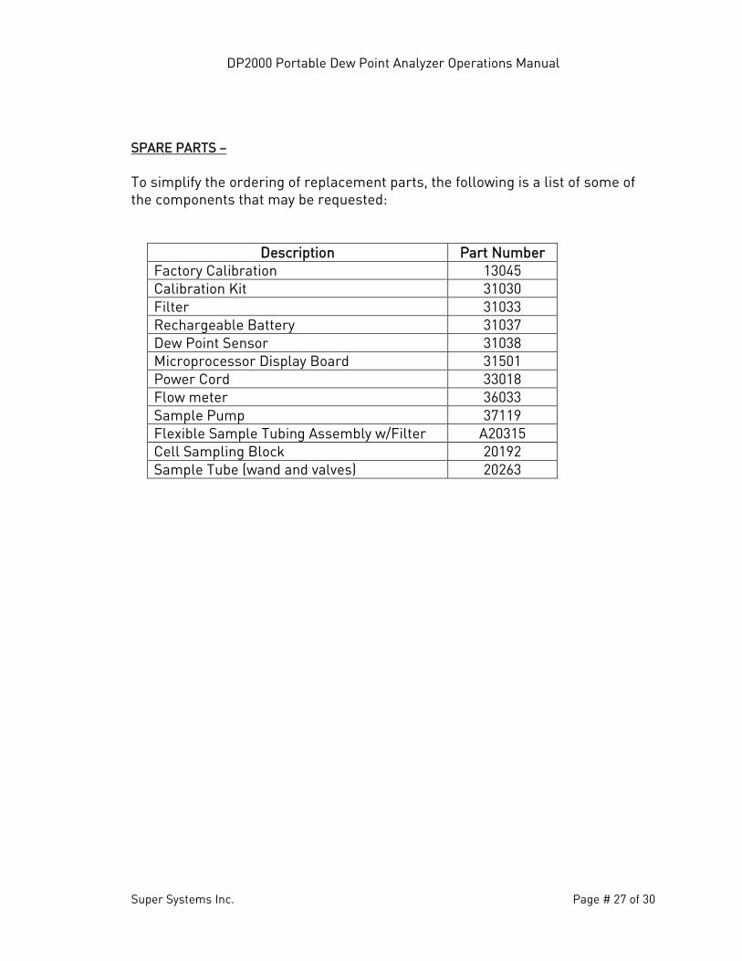
SPARE PARTS – To simplify the ordering of replacement parts, the following is a list of some of the components that may be requested:
Description Part Number Factory Calibration 13045 Calibration Kit 31030 Filter 31033 Rechargeable Battery 31037 Dew Point Sensor 31038 Microprocessor Display Board 31501 Power Cord 33018 Flow meter 36033 Sample Pump 37119 Flexible Sample Tubing Assembly w/Filter A20315 Cell Sampling Block 20192 Sample Tube (wand and valves) 20263
DP2000 Portable Dew Point Analyzer Operations Manual
Super Systems Inc. Page # 28 of 30
APPENDIX “A” –
Temp Temp Temp(oF) 11.3% 75.3% (oF) 11.3% 75.3% (oF) 11.3% 75.3%
69.00 12.94 60.86 72.70 15.81 64.44 76.40 18.68 68.0169.10 13.01 60.96 72.80 15.89 64.54 76.50 18.75 68.1169.20 13.09 61.06 72.90 15.97 64.63 76.60 18.83 68.2069.30 13.17 61.16 73.00 16.04 64.73 76.70 18.91 68.3069.40 13.25 61.25 73.10 16.12 64.82 76.80 18.99 68.4069.50 13.33 61.35 73.20 16.20 64.92 76.90 19.06 68.4969.60 13.40 61.45 73.30 16.28 65.02 77.00 19.14 68.5969.70 13.48 61.54 73.40 16.35 65.11 77.10 19.22 68.6969.80 13.56 61.64 73.50 16.43 65.21 77.20 19.30 68.7869.90 13.63 61.74 73.60 16.51 65.31 77.30 19.37 68.8870.00 13.71 61.83 73.70 16.59 65.40 77.40 19.45 68.9770.10 13.79 61.93 73.80 16.66 65.50 77.50 19.53 69.0770.20 13.87 62.03 73.90 16.74 65.60 77.60 19.61 69.1770.30 13.95 62.12 74.00 16.82 65.69 77.70 19.68 69.2670.40 14.02 62.22 74.10 16.90 65.79 77.80 19.76 69.3670.50 14.10 62.32 74.20 16.97 65.89 77.90 19.84 69.4670.60 14.18 62.41 74.30 17.05 65.98 78.00 19.91 69.5570.70 14.26 62.51 74.40 17.13 66.08 78.10 19.99 69.6570.80 14.33 62.60 74.50 17.21 66.18 78.20 20.07 69.7570.90 14.41 62.70 74.60 17.28 66.27 78.30 20.14 69.8471.00 14.49 62.80 74.70 17.36 66.37 78.40 20.22 69.9471.10 14.57 62.89 74.80 17.44 66.47 78.50 20.30 70.0471.20 14.65 62.99 74.90 17.52 66.56 78.60 20.38 70.1371.30 14.72 63.09 75.00 17.59 66.66 78.70 20.46 70.2371.40 14.80 63.18 75.10 17.67 66.76 78.80 20.53 70.3371.50 14.88 63.28 75.20 17.75 66.85 78.90 20.61 70.4271.60 14.96 63.38 75.30 17.83 66.95 79.00 20.69 70.5271.70 15.03 63.47 75.40 17.90 67.04 79.10 20.76 70.6171.80 15.11 63.57 75.50 17.98 67.14 79.20 20.84 70.7171.90 15.19 63.67 75.60 18.06 67.24 79.30 20.92 70.8172.00 15.27 63.76 75.70 18.14 67.33 79.40 21.00 70.9072.10 15.34 63.86 75.80 18.21 67.43 79.50 21.07 71.0072.20 15.42 63.96 75.90 18.29 67.53 79.60 21.15 71.1072.30 15.50 64.05 76.00 18.37 67.62 79.70 21.23 71.1972.40 15.58 64.15 76.10 18.44 67.72 79.80 21.31 71.2972.50 15.65 64.25 76.20 18.52 67.82 79.90 21.38 71.3972.60 15.73 64.34 76.30 18.60 67.91 80.00 21.46 71.48
Theoretical Dew Point Values For Calibration Verification (Fahrenheit)
Percent RH Percent RH Percent RH
DP2000 Portable Dew Point Analyzer Operations Manual
Super Systems Inc. Page # 29 of 30
APPENDIX “B” –
Temp Temp Temp(oC) 11.3% 75.3% (oC) 11.3% 75.3% (oC) 11.3% 75.3%
20.56 -10.59 16.03 22.61 -8.99 18.02 24.67 -7.40 20.0120.61 -10.55 16.09 22.67 -8.95 18.08 24.72 -7.36 20.0620.67 -10.51 16.14 22.72 -8.91 18.13 24.78 -7.32 20.1120.72 -10.46 16.20 22.78 -8.87 18.18 24.83 -7.27 20.1720.78 -10.42 16.25 22.83 -8.82 18.23 24.89 -7.23 20.2220.83 -10.37 16.31 22.89 -8.78 18.29 24.94 -7.19 20.2720.89 -10.33 16.36 22.94 -8.73 18.34 25.00 -7.14 20.3320.94 -10.29 16.41 23.00 -8.69 18.39 25.06 -7.10 20.3821.00 -10.24 16.47 23.06 -8.65 18.45 25.11 -7.06 20.4321.06 -10.21 16.52 23.11 -8.61 18.51 25.17 -7.02 20.4921.11 -10.16 16.57 23.17 -8.56 18.56 25.22 -6.97 20.5421.17 -10.12 16.63 23.22 -8.52 18.61 25.28 -6.93 20.5921.22 -10.07 16.68 23.28 -8.48 18.67 25.33 -6.88 20.6521.28 -10.03 16.73 23.33 -8.43 18.72 25.39 -6.84 20.7021.33 -9.99 16.79 23.39 -8.39 18.77 25.44 -6.80 20.7621.39 -9.94 16.84 23.44 -8.35 18.83 25.50 -6.76 20.8121.44 -9.90 16.89 23.50 -8.31 18.88 25.56 -6.72 20.8621.50 -9.86 16.95 23.56 -8.26 18.93 25.61 -6.67 20.9221.56 -9.82 17.00 23.61 -8.22 18.99 25.67 -6.63 20.9721.61 -9.77 17.06 23.67 -8.18 19.04 25.72 -6.59 21.0221.67 -9.73 17.11 23.72 -8.13 19.09 25.78 -6.54 21.0821.72 -9.68 17.16 23.78 -8.09 19.15 25.83 -6.50 21.1321.78 -9.64 17.22 23.83 -8.04 19.20 25.89 -6.46 21.1821.83 -9.60 17.27 23.89 -8.01 19.26 25.94 -6.41 21.2421.89 -9.56 17.32 23.94 -7.96 19.31 26.00 -6.37 21.2921.94 -9.51 17.38 24.00 -7.92 19.36 26.06 -6.33 21.3422.00 -9.47 17.43 24.06 -7.87 19.42 26.11 -6.28 21.4022.06 -9.43 17.48 24.11 -7.83 19.47 26.17 -6.24 21.4522.11 -9.38 17.54 24.17 -7.79 19.52 26.22 -6.20 21.5122.17 -9.34 17.59 24.22 -7.74 19.58 26.28 -6.16 21.5622.22 -9.29 17.64 24.28 -7.70 19.63 26.33 -6.11 21.6122.28 -9.26 17.70 24.33 -7.66 19.68 26.39 -6.07 21.6722.33 -9.21 17.76 24.39 -7.62 19.74 26.44 -6.03 21.7222.39 -9.17 17.81 24.44 -7.57 19.79 26.50 -5.98 21.7722.44 -9.12 17.86 24.50 -7.53 19.84 26.56 -5.94 21.8322.50 -9.08 17.92 24.56 -7.49 19.90 26.61 -5.90 21.8822.56 -9.04 17.97 24.61 -7.44 19.95 26.67 -5.86 21.93
Percent RH Percent RH
Theoretical Dew Point Values For Calibration Verification (Celsius)
Percent RH
DP2000 Portable Dew Point Analyzer Operations Manual
Super Systems Inc. Page # 30 of 30
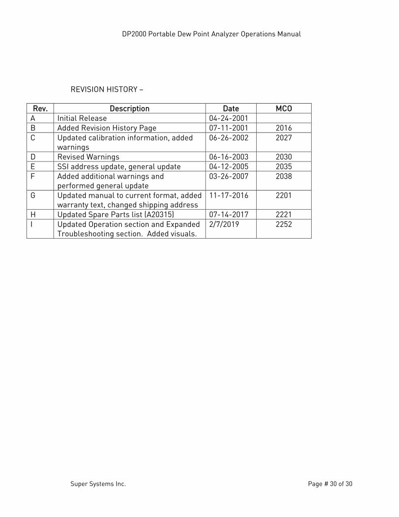
REVISION HISTORY –
Rev. Description Date MCO A Initial Release 04-24-2001 B Added Revision History Page 07-11-2001 2016 C Updated calibration information, added
warnings 06-26-2002 2027
D Revised Warnings 06-16-2003 2030 E SSI address update, general update 04-12-2005 2035 F Added additional warnings and
performed general update 03-26-2007 2038
G Updated manual to current format, added warranty text, changed shipping address
11-17-2016 2201
H Updated Spare Parts list (A20315) 07-14-2017 2221 I Updated Operation section and Expanded
Troubleshooting section. Added visuals. 2/7/2019 2252