Documentation BC8050 und BC8150 - Beckhoff Automation · 2.3The Beckhoff Bus Terminal system Up to...
93
Documentation BC8050 und BC8150 Bus Terminal Controller with RS485 or RS232 Interface 3.0.0 2017-07-18 Version: Date:
Transcript of Documentation BC8050 und BC8150 - Beckhoff Automation · 2.3The Beckhoff Bus Terminal system Up to...
Documentation
BC8050 und BC8150
Bus Terminal Controller with RS485 or RS232 Interface
3.0.02017-07-18
Version:Date:

Table of contents
BC8050 und BC8150 3Version: 3.0.0
Table of contents1 Foreword .................................................................................................................................................... 5
1.1 Notes on the documentation........................................................................................................... 51.2 Safety instructions .......................................................................................................................... 61.3 Documentation issue status............................................................................................................ 7
2 Product overview....................................................................................................................................... 82.1 BCxx50 Overview ........................................................................................................................... 82.2 The principle of the Bus Terminal ................................................................................................... 92.3 The Beckhoff Bus Terminal system ................................................................................................ 92.4 Technical data .............................................................................................................................. 11
2.4.1 Technical Data - BCxx50 ................................................................................................ 112.4.2 Technical data - RS485 ................................................................................................... 132.4.3 Technical Data - RS232................................................................................................... 142.4.4 Technical Data - PLC....................................................................................................... 15
3 Mounting and wiring ............................................................................................................................... 163.1 Mounting ....................................................................................................................................... 16
3.1.1 Dimensions ...................................................................................................................... 163.1.2 Installation........................................................................................................................ 17
3.2 Wiring............................................................................................................................................ 183.2.1 Potential groups, insulation testing and PE ..................................................................... 183.2.2 Power supply.................................................................................................................... 193.2.3 Programming cable .......................................................................................................... 213.2.4 RS232 Connection........................................................................................................... 223.2.5 RS485 connection............................................................................................................ 23
4 Parameterization and Commissioning .................................................................................................. 244.1 Start-up behavior of the Bus Terminal Controller ......................................................................... 244.2 Setting the Address ...................................................................................................................... 254.3 Baud rate ...................................................................................................................................... 264.4 Configuration ................................................................................................................................ 26
4.4.1 Overview .......................................................................................................................... 264.4.2 Creating a TwinCAT configuration ................................................................................... 284.4.3 Downloading a TwinCAT configuration............................................................................ 284.4.4 Uploading a TwinCAT configuration ................................................................................ 304.4.5 Resources in the Bus Terminal Controller ....................................................................... 324.4.6 ADS connection via serial interface ................................................................................. 34
4.5 RS232 interface ............................................................................................................................ 364.5.1 TwinCAT Configuration - RS232 Interface....................................................................... 36
4.6 K-bus ............................................................................................................................................ 384.7 Configuration software KS2000 .................................................................................................... 40
5 Programming ........................................................................................................................................... 415.1 BCxx50 PLC features ................................................................................................................... 415.2 TwinCAT PLC ............................................................................................................................... 415.3 TwinCAT PLC - Error codes ......................................................................................................... 425.4 Remanent data ............................................................................................................................. 455.5 Allocated flags .............................................................................................................................. 465.6 Local process image in delivery state........................................................................................... 465.7 Mapping the Bus Terminals .......................................................................................................... 48
Table of contents
BC8050 und BC81504 Version: 3.0.0
5.8 Local process image in the TwinCAT configuration...................................................................... 495.9 Creating a boot project ................................................................................................................. 505.10 Communication between TwinCAT and BX/BCxx50 .................................................................... 505.11 Up- and downloading of programs................................................................................................ 525.12 Libraries ........................................................................................................................................ 55
5.12.1 Libraries overview ............................................................................................................ 555.12.2 Seriell_Set data structure................................................................................................. 565.12.3 TcBaseBCxx50 ................................................................................................................ 58
5.13 Program transfer........................................................................................................................... 615.13.1 Program transfer via the serial interface .......................................................................... 61
5.14 Process image .............................................................................................................................. 625.14.1 Modbus Process Image ................................................................................................... 625.14.2 KS8000 Process Image ................................................................................................... 62
6 RS232 - Interface ..................................................................................................................................... 646.1 Protocol......................................................................................................................................... 64
6.1.1 Modbus ............................................................................................................................ 646.1.2 Protocol Overview............................................................................................................ 746.1.3 KS8000 protocol .............................................................................................................. 74
6.2 Introduction to the system............................................................................................................. 776.2.1 Overview of the physical structure of RS232 ................................................................... 776.2.2 Topology of the physical RS232 structure ....................................................................... 78
7 Error handling and diagnosis................................................................................................................. 797.1 Diagnostics ................................................................................................................................... 797.2 Diagnostic LEDs ........................................................................................................................... 80
8 Appendix .................................................................................................................................................. 828.1 First steps with the BC8150.......................................................................................................... 828.2 Switching between controllers ...................................................................................................... 828.3 Example programs for serial communication................................................................................ 848.4 Firmware Update .......................................................................................................................... 858.5 General operating conditions........................................................................................................ 878.6 Test standards for device testing.................................................................................................. 908.7 Bibliography .................................................................................................................................. 908.8 List of Abbreviations ..................................................................................................................... 908.9 Support and Service ..................................................................................................................... 91
Foreword
BC8050 und BC8150 5Version: 3.0.0
1 Foreword
1.1 Notes on the documentation
Intended audience
This description is only intended for the use of trained specialists in control and automation engineering whoare familiar with the applicable national standards.It is essential that the documentation and the following notes and explanations are followed when installingand commissioning these components.It is the duty of the technical personnel to use the documentation published at the respective time of eachinstallation and commissioning.
The responsible staff must ensure that the application or use of the products described satisfy all therequirements for safety, including all the relevant laws, regulations, guidelines and standards.
Disclaimer
The documentation has been prepared with care. The products described are, however, constantly underdevelopment.
We reserve the right to revise and change the documentation at any time and without prior announcement.
No claims for the modification of products that have already been supplied may be made on the basis of thedata, diagrams and descriptions in this documentation.
Trademarks
Beckhoff®, TwinCAT®, EtherCAT®, Safety over EtherCAT®, TwinSAFE®, XFC® and XTS® are registeredtrademarks of and licensed by Beckhoff Automation GmbH.Other designations used in this publication may be trademarks whose use by third parties for their ownpurposes could violate the rights of the owners.
Patent Pending
The EtherCAT Technology is covered, including but not limited to the following patent applications andpatents: EP1590927, EP1789857, DE102004044764, DE102007017835 with corresponding applications orregistrations in various other countries.
The TwinCAT Technology is covered, including but not limited to the following patent applications andpatents: EP0851348, US6167425 with corresponding applications or registrations in various other countries.
EtherCAT® is registered trademark and patented technology, licensed by Beckhoff Automation GmbH,Germany
Copyright
© Beckhoff Automation GmbH & Co. KG, Germany.The reproduction, distribution and utilization of this document as well as the communication of its contents toothers without express authorization are prohibited.Offenders will be held liable for the payment of damages. All rights reserved in the event of the grant of apatent, utility model or design.
Foreword
BC8050 und BC81506 Version: 3.0.0
1.2 Safety instructions
Safety regulations
Please note the following safety instructions and explanations!Product-specific safety instructions can be found on following pages or in the areas mounting, wiring,commissioning etc.
Exclusion of liability
All the components are supplied in particular hardware and software configurations appropriate for theapplication. Modifications to hardware or software configurations other than those described in thedocumentation are not permitted, and nullify the liability of Beckhoff Automation GmbH & Co. KG.
Personnel qualification
This description is only intended for trained specialists in control, automation and drive engineering who arefamiliar with the applicable national standards.
Description of symbols
In this documentation the following symbols are used with an accompanying safety instruction or note. Thesafety instructions must be read carefully and followed without fail!
DANGER
Serious risk of injury!Failure to follow the safety instructions associated with this symbol directly endangers thelife and health of persons.
WARNING
Risk of injury!Failure to follow the safety instructions associated with this symbol endangers the life andhealth of persons.
CAUTION
Personal injuries!Failure to follow the safety instructions associated with this symbol can lead to injuries topersons.
Attention
Damage to the environment or devicesFailure to follow the instructions associated with this symbol can lead to damage to the en-vironment or equipment.
Note
Tip or pointerThis symbol indicates information that contributes to better understanding.
Foreword
BC8050 und BC8150 7Version: 3.0.0
1.3 Documentation issue statusVersion Comment3.0.0 • Migration2.0.0 • BC8050 added1.1.1 • ADS communication example added [} 84]1.1.0 • Notes to meet the UL requirements added.1.0.1 • Minor routine corrections1.0.0 • First public issue (only available in German)
BC8150 firmware
For updating your firmware you need a serial cable, the KS2000 configuration software, or the firmwareupdate program.
Document version BC8050 BC8150Firmware version Hardware version Firmware version Hardware version
3.0.0 B0 04 B1 082.0.0 B0 00 B1 041.1.1 - - B0 001.1.0 - - B0 001.0.1 - - B0 001.0.0 - - B0 00
The firmware and hardware versions (delivery state) can be found on the sticker on the underside of the BusTerminal Controller.
Product overview
BC8050 und BC81508 Version: 3.0.0
2 Product overview
2.1 BCxx50 OverviewBus Terminal Controllers are Bus Couplers with integrated PLC functionality. The BCxx50 Bus TerminalControllers have a fieldbus interface, are intelligent slaves and can be used as decentralized intelligencewithin the system. They are located in a cost-optimized and compact housing. In contrast to the BCxx00range, the BCxx50 range supports up to 255 Bus Terminals via the K-Bus extension.
The Bus Terminal Controller is programmed using the TwinCAT programming system according to IEC61131-3. The BCxx50 configuration/programming interface is used for loading the PLC program. If theTwinCAT software PLC is in use, the PLC program can also be loaded via the fieldbus.
The inputs and outputs of the connected Bus Terminals are assigned in the default setting of the mini-PLC.Each individual Bus Terminal can be configured in such a way that it exchanges data directly through thefieldbus with the higher-level automation device. Similarly, pre-processed data can be exchanged betweenthe Bus Terminal Controller and the higher-level controller via the fieldbus.
Fieldbus interface
The variants of the BCxx50 series Bus Terminal Controllers differ in terms of their fieldbus interfaces.Various versions cover the most important fieldbus systems:
• BC3150: PROFIBUS DP
• BC5150: CANopen
• BC5250: DeviceNet
• BC8050: RS485, various protocols
• BC8150: RS232, various protocols
Programming
The BCxx50 devices are programmed according to the powerful IEC 61131-3 standard. Like for all otherBECKHOFF controllers, the TwinCAT automation software is the basis for parameterization andprogramming. Users therefore have the familiar TwinCAT tools available, e.g. PLC programming interface,System Manager and TwinCAT Scope. Data is exchanged optionally via the serial interface (COM1) or viathe fieldbus through Beckhoff PC FCxxxx fieldbus cards.
Configuration
The configuration is also carried out using TwinCAT. The fieldbus interface can be configured andparameterized via the System Manager. The System Manager can read all connected devices and BusTerminals. After the parameterization, the configuration is saved on the BCxx50 via the serial interface. Theconfiguration thus created can be accessed again later.
Product overview
BC8050 und BC8150 9Version: 3.0.0
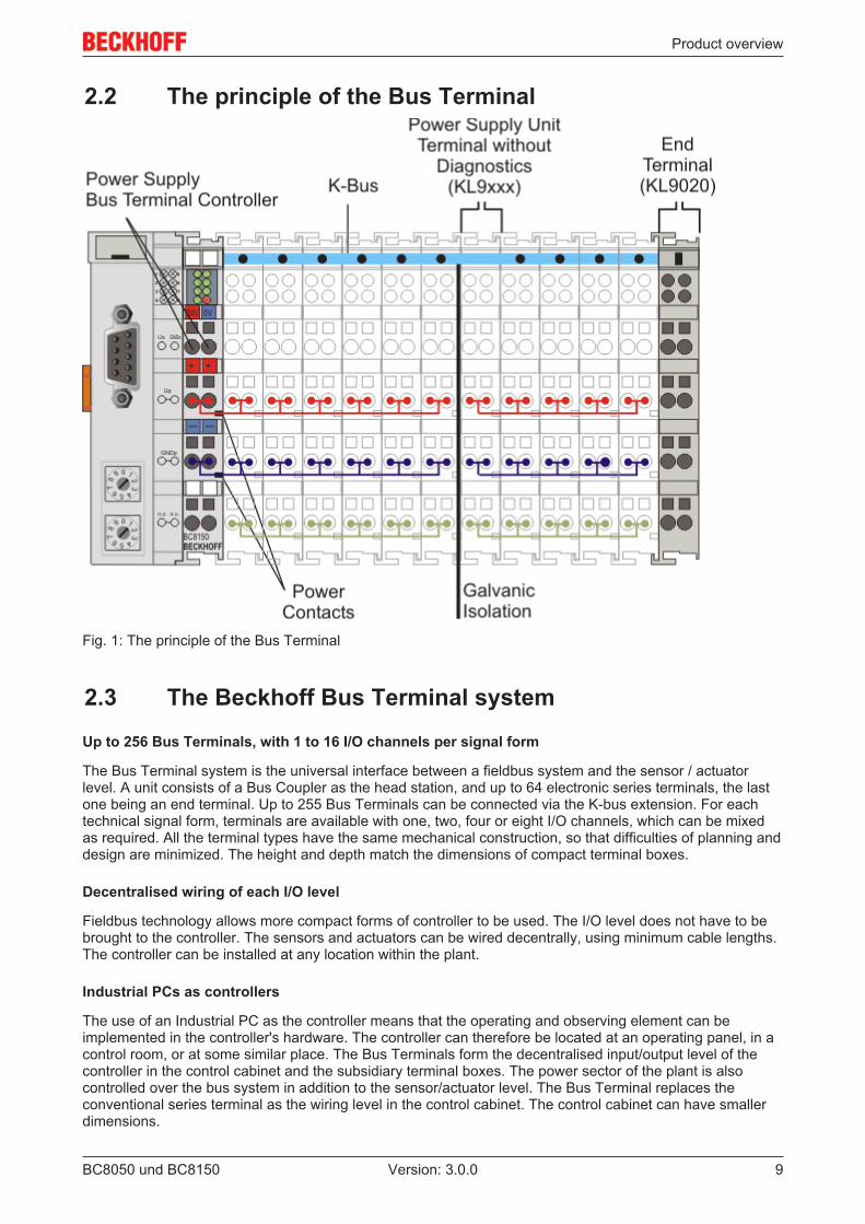
2.2 The principle of the Bus Terminal
Fig. 1: The principle of the Bus Terminal
2.3 The Beckhoff Bus Terminal system
Up to 256 Bus Terminals, with 1 to 16 I/O channels per signal form
The Bus Terminal system is the universal interface between a fieldbus system and the sensor / actuatorlevel. A unit consists of a Bus Coupler as the head station, and up to 64 electronic series terminals, the lastone being an end terminal. Up to 255 Bus Terminals can be connected via the K-bus extension. For eachtechnical signal form, terminals are available with one, two, four or eight I/O channels, which can be mixedas required. All the terminal types have the same mechanical construction, so that difficulties of planning anddesign are minimized. The height and depth match the dimensions of compact terminal boxes.
Decentralised wiring of each I/O level
Fieldbus technology allows more compact forms of controller to be used. The I/O level does not have to bebrought to the controller. The sensors and actuators can be wired decentrally, using minimum cable lengths.The controller can be installed at any location within the plant.
Industrial PCs as controllers
The use of an Industrial PC as the controller means that the operating and observing element can beimplemented in the controller's hardware. The controller can therefore be located at an operating panel, in acontrol room, or at some similar place. The Bus Terminals form the decentralised input/output level of thecontroller in the control cabinet and the subsidiary terminal boxes. The power sector of the plant is alsocontrolled over the bus system in addition to the sensor/actuator level. The Bus Terminal replaces theconventional series terminal as the wiring level in the control cabinet. The control cabinet can have smallerdimensions.
Product overview
BC8050 und BC815010 Version: 3.0.0
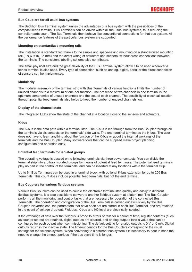
Bus Couplers for all usual bus systems
The Beckhoff Bus Terminal system unites the advantages of a bus system with the possibilities of thecompact series terminal. Bus Terminals can be driven within all the usual bus systems, thus reducing thecontroller parts count. The Bus Terminals then behave like conventional connections for that bus system. Allthe performance features of the particular bus system are supported.
Mounting on standardized mounting rails
The installation is standardized thanks to the simple and space-saving mounting on a standardized mountingrail (EN 60715, 35 mm) and the direct wiring of actuators and sensors, without cross connections betweenthe terminals. The consistent labelling scheme also contributes.
The small physical size and the great flexibility of the Bus Terminal system allow it to be used wherever aseries terminal is also used. Every type of connection, such as analog, digital, serial or the direct connectionof sensors can be implemented.
Modularity
The modular assembly of the terminal strip with Bus Terminals of various functions limits the number ofunused channels to a maximum of one per function. The presence of two channels in one terminal is theoptimum compromise of unused channels and the cost of each channel. The possibility of electrical isolationthrough potential feed terminals also helps to keep the number of unused channels low.
Display of the channel state
The integrated LEDs show the state of the channel at a location close to the sensors and actuators.
K-bus
The K-bus is the data path within a terminal strip. The K-bus is led through from the Bus Coupler through allthe terminals via six contacts on the terminals' side walls. The end terminal terminates the K-bus. The userdoes not have to learn anything about the function of the K-bus or about the internal workings of theterminals and the Bus Coupler. Many software tools that can be supplied make project planning,configuration and operation easy.
Potential feed terminals for isolated groups
The operating voltage is passed on to following terminals via three power contacts. You can divide theterminal strip into arbitrary isolated groups by means of potential feed terminals. The potential feed terminalsplay no part in the control of the terminals, and can be inserted at any locations within the terminal strip.
Up to 64 Bus Terminals can be used in a terminal block, with optional K-bus extension for up to 256 BusTerminals. This count does include potential feed terminals, but not the end terminal.
Bus Couplers for various fieldbus systems
Various Bus Couplers can be used to couple the electronic terminal strip quickly and easily to differentfieldbus systems. It is also possible to convert to another fieldbus system at a later time. The Bus Couplerperforms all the monitoring and control tasks that are necessary for operation of the connected BusTerminals. The operation and configuration of the Bus Terminals is carried out exclusively by the BusCoupler. Nevertheless, the parameters that have been set are stored in each Bus Terminal, and are retainedin the event of voltage drop-out. Fieldbus, K-bus and I/O level are electrically isolated.
If the exchange of data over the fieldbus is prone to errors or fails for a period of time, register contents (suchas counter states) are retained, digital outputs are cleared, and analog outputs take a value that can beconfigured for each output when commissioning. The default setting for analog outputs is 0 V or 0 mA. Digitaloutputs return in the inactive state. The timeout periods for the Bus Couplers correspond to the usualsettings for the fieldbus system. When converting to a different bus system it is necessary to bear in mind theneed to change the timeout periods if the bus cycle time is longer.
Product overview
BC8050 und BC8150 11Version: 3.0.0
The interfaces
A Bus Coupler has six different methods of connection. These interfaces are designed as plug connectorsand as spring-loaded terminals.
2.4 Technical data
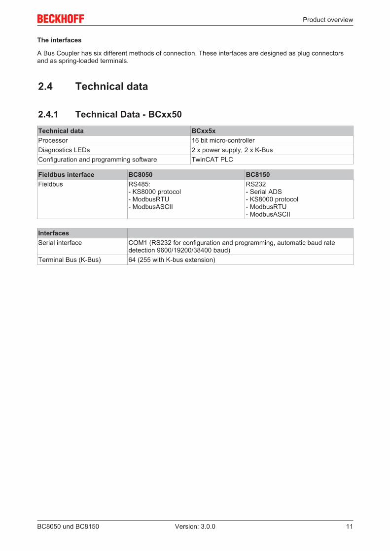
2.4.1 Technical Data - BCxx50Technical data BCxx5xProcessor 16 bit micro-controllerDiagnostics LEDs 2 x power supply, 2 x K-BusConfiguration and programming software TwinCAT PLC
Fieldbus interface BC8050 BC8150Fieldbus RS485:
- KS8000 protocol- ModbusRTU- ModbusASCII
RS232- Serial ADS- KS8000 protocol- ModbusRTU- ModbusASCII
InterfacesSerial interface COM1 (RS232 for configuration and programming, automatic baud rate
detection 9600/19200/38400 baud)Terminal Bus (K-Bus) 64 (255 with K-bus extension)
Product overview
BC8050 und BC815012 Version: 3.0.0
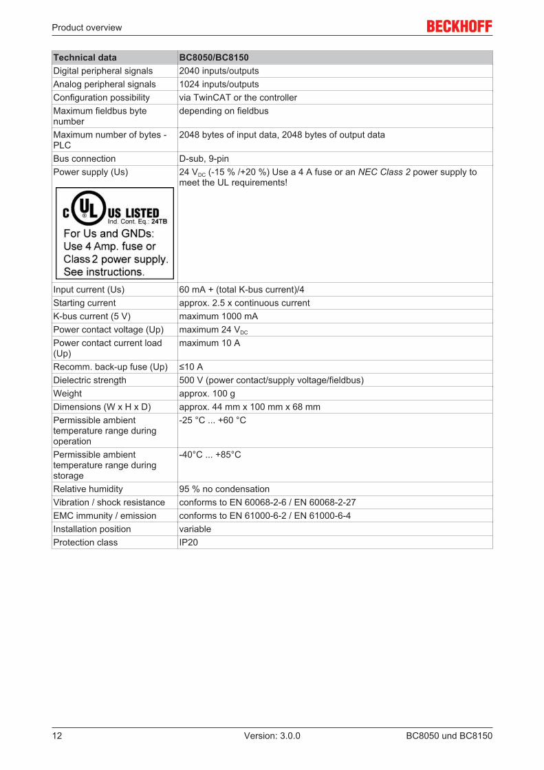
Technical data BC8050/BC8150Digital peripheral signals 2040 inputs/outputsAnalog peripheral signals 1024 inputs/outputsConfiguration possibility via TwinCAT or the controllerMaximum fieldbus bytenumber
depending on fieldbus
Maximum number of bytes -PLC
2048 bytes of input data, 2048 bytes of output data
Bus connection D-sub, 9-pinPower supply (Us) 24 VDC (-15 % /+20 %) Use a 4 A fuse or an NEC Class 2 power supply to
meet the UL requirements!
Input current (Us) 60 mA + (total K-bus current)/4Starting current approx. 2.5 x continuous currentK-bus current (5 V) maximum 1000 mAPower contact voltage (Up) maximum 24 VDC
Power contact current load(Up)
maximum 10 A
Recomm. back-up fuse (Up) ≤10 ADielectric strength 500 V (power contact/supply voltage/fieldbus)Weight approx. 100 gDimensions (W x H x D) approx. 44 mm x 100 mm x 68 mmPermissible ambienttemperature range duringoperation
-25 °C ... +60 °C
Permissible ambienttemperature range duringstorage
-40°C ... +85°C
Relative humidity 95 % no condensationVibration / shock resistance conforms to EN 60068-2-6 / EN 60068-2-27EMC immunity / emission conforms to EN 61000-6-2 / EN 61000-6-4Installation position variableProtection class IP20
Product overview
BC8050 und BC8150 13Version: 3.0.0
2.4.2 Technical data - RS485
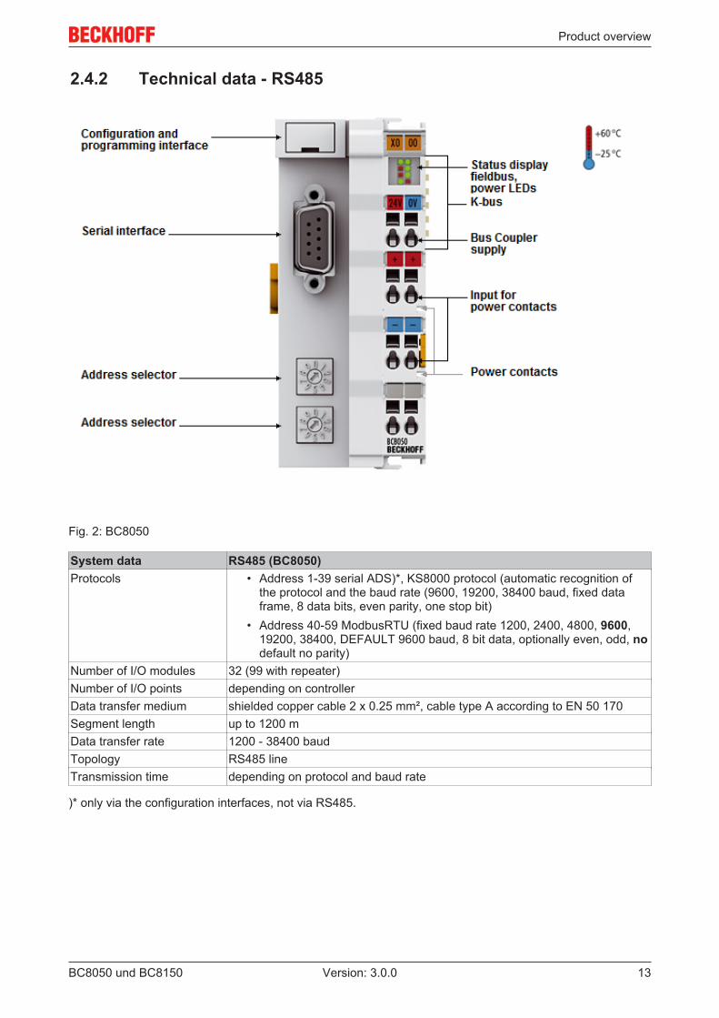
Fig. 2: BC8050
System data RS485 (BC8050)Protocols • Address 1-39 serial ADS)*, KS8000 protocol (automatic recognition of
the protocol and the baud rate (9600, 19200, 38400 baud, fixed dataframe, 8 data bits, even parity, one stop bit)
• Address 40-59 ModbusRTU (fixed baud rate 1200, 2400, 4800, 9600,19200, 38400, DEFAULT 9600 baud, 8 bit data, optionally even, odd, nodefault no parity)
Number of I/O modules 32 (99 with repeater)Number of I/O points depending on controllerData transfer medium shielded copper cable 2 x 0.25 mm², cable type A according to EN 50 170Segment length up to 1200 mData transfer rate 1200 - 38400 baudTopology RS485 lineTransmission time depending on protocol and baud rate
)* only via the configuration interfaces, not via RS485.
Product overview
BC8050 und BC815014 Version: 3.0.0
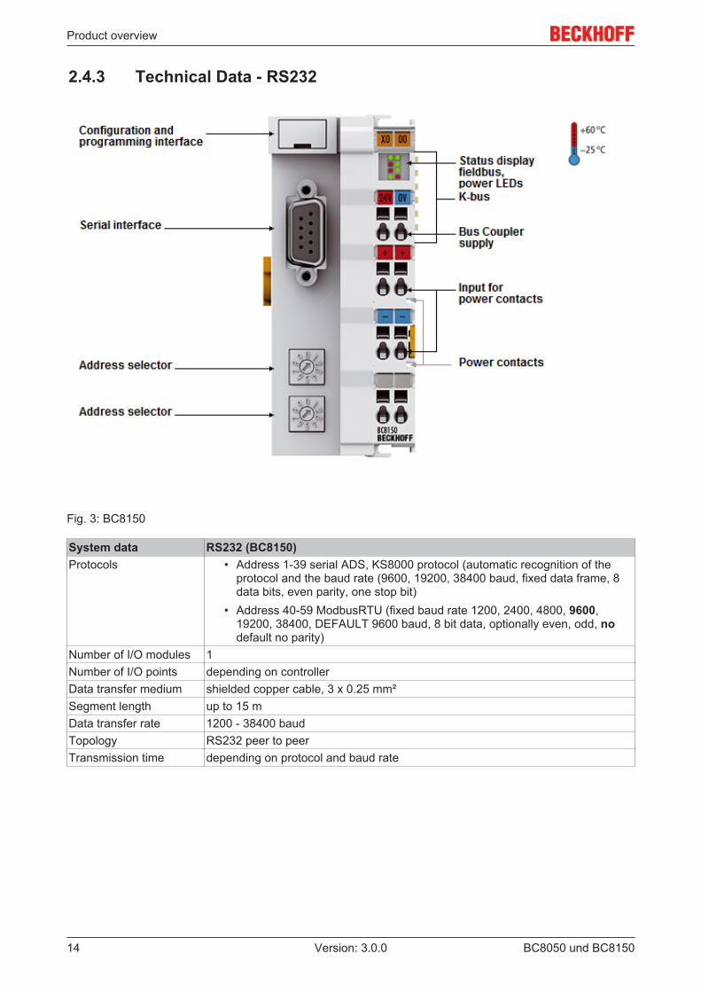
2.4.3 Technical Data - RS232
Fig. 3: BC8150
System data RS232 (BC8150)Protocols • Address 1-39 serial ADS, KS8000 protocol (automatic recognition of the
protocol and the baud rate (9600, 19200, 38400 baud, fixed data frame, 8data bits, even parity, one stop bit)
• Address 40-59 ModbusRTU (fixed baud rate 1200, 2400, 4800, 9600,19200, 38400, DEFAULT 9600 baud, 8 bit data, optionally even, odd, nodefault no parity)
Number of I/O modules 1Number of I/O points depending on controllerData transfer medium shielded copper cable, 3 x 0.25 mm²Segment length up to 15 mData transfer rate 1200 - 38400 baudTopology RS232 peer to peerTransmission time depending on protocol and baud rate
Product overview
BC8050 und BC8150 15Version: 3.0.0
2.4.4 Technical Data - PLCPLC data BCxx5xProgrammability via serial programming interface or via the fieldbusProgram memory 48 kbyteSource code memory 128 kbyteData memory 32 kbyteRemanent flags 2 kbytePLC cycle time Approx. 3.0 ms for 1000 IL commands (without I/O cycle)Programming languages IEC 6-1131-3 (IL, LD, FBD, ST, SFC)Runtime 1 SPS TaskOnline Change YesUp/Down Load Code Yes/Yes
Mounting and wiring
BC8050 und BC815016 Version: 3.0.0
3 Mounting and wiring
3.1 Mounting
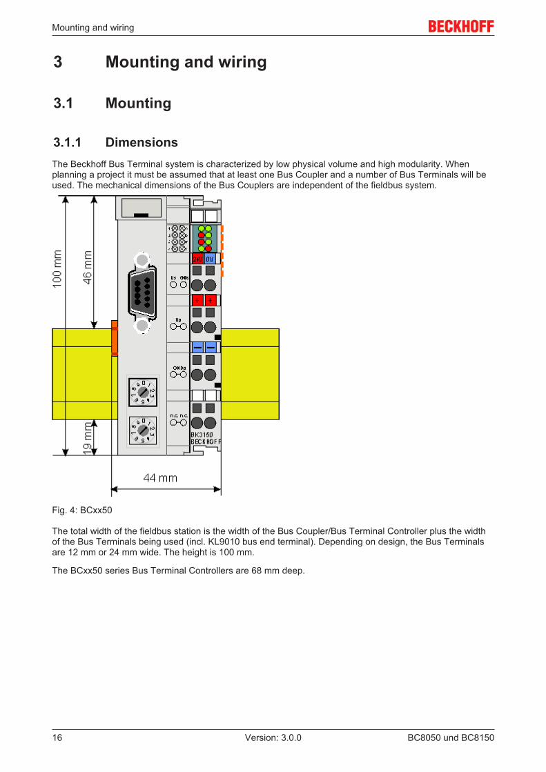
3.1.1 DimensionsThe Beckhoff Bus Terminal system is characterized by low physical volume and high modularity. Whenplanning a project it must be assumed that at least one Bus Coupler and a number of Bus Terminals will beused. The mechanical dimensions of the Bus Couplers are independent of the fieldbus system.
Fig. 4: BCxx50
The total width of the fieldbus station is the width of the Bus Coupler/Bus Terminal Controller plus the widthof the Bus Terminals being used (incl. KL9010 bus end terminal). Depending on design, the Bus Terminalsare 12 mm or 24 mm wide. The height is 100 mm.
The BCxx50 series Bus Terminal Controllers are 68 mm deep.
Mounting and wiring
BC8050 und BC8150 17Version: 3.0.0
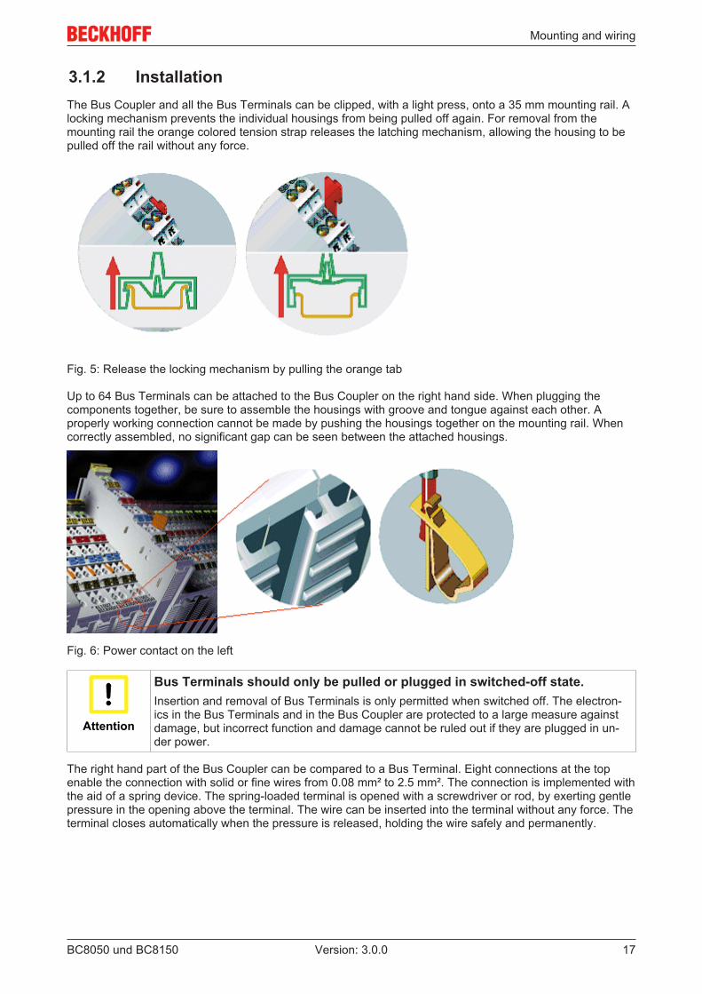
3.1.2 InstallationThe Bus Coupler and all the Bus Terminals can be clipped, with a light press, onto a 35 mm mounting rail. Alocking mechanism prevents the individual housings from being pulled off again. For removal from themounting rail the orange colored tension strap releases the latching mechanism, allowing the housing to bepulled off the rail without any force.
Fig. 5: Release the locking mechanism by pulling the orange tab
Up to 64 Bus Terminals can be attached to the Bus Coupler on the right hand side. When plugging thecomponents together, be sure to assemble the housings with groove and tongue against each other. Aproperly working connection cannot be made by pushing the housings together on the mounting rail. Whencorrectly assembled, no significant gap can be seen between the attached housings.
Fig. 6: Power contact on the left
Attention
Bus Terminals should only be pulled or plugged in switched-off state.Insertion and removal of Bus Terminals is only permitted when switched off. The electron-ics in the Bus Terminals and in the Bus Coupler are protected to a large measure againstdamage, but incorrect function and damage cannot be ruled out if they are plugged in un-der power.
The right hand part of the Bus Coupler can be compared to a Bus Terminal. Eight connections at the topenable the connection with solid or fine wires from 0.08 mm² to 2.5 mm². The connection is implemented withthe aid of a spring device. The spring-loaded terminal is opened with a screwdriver or rod, by exerting gentlepressure in the opening above the terminal. The wire can be inserted into the terminal without any force. Theterminal closes automatically when the pressure is released, holding the wire safely and permanently.
Mounting and wiring
BC8050 und BC815018 Version: 3.0.0
3.2 Wiring
3.2.1 Potential groups, insulation testing and PE
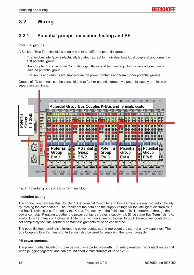
Potential groups
A Beckhoff Bus Terminal block usually has three different potential groups:
• The fieldbus interface is electrically isolated (except for individual Low Cost couplers) and forms thefirst potential group.
• Bus Coupler / Bus Terminal Controller logic, K-bus and terminal logic form a second electricallyisolated potential group.
• The inputs and outputs are supplied via the power contacts and form further potential groups.
Groups of I/O terminals can be consolidated to further potential groups via potential supply terminals orseparation terminals.
Fig. 7: Potential groups of a Bus Terminal block
Insulation testing
The connection between Bus Coupler / Bus Terminal Controller and Bus Terminals is realized automaticallyby latching the components. The transfer of the data and the supply voltage for the intelligent electronics inthe Bus Terminals is performed by the K-bus. The supply of the field electronics is performed through thepower contacts. Plugging together the power contacts creates a supply rail. Since some Bus Terminals (e.g.analog Bus Terminals or 4-channel digital Bus Terminals) are not looped through these power contacts ornot completely the Bus Terminal contact assignments must be considered.
The potential feed terminals interrupt the power contacts, and represent the start of a new supply rail. TheBus Coupler / Bus Terminal Controller can also be used for supplying the power contacts.
PE power contacts
The power contact labelled PE can be used as a protective earth. For safety reasons this contact mates firstwhen plugging together, and can ground short-circuit currents of up to 125 A.
Mounting and wiring
BC8050 und BC8150 19Version: 3.0.0
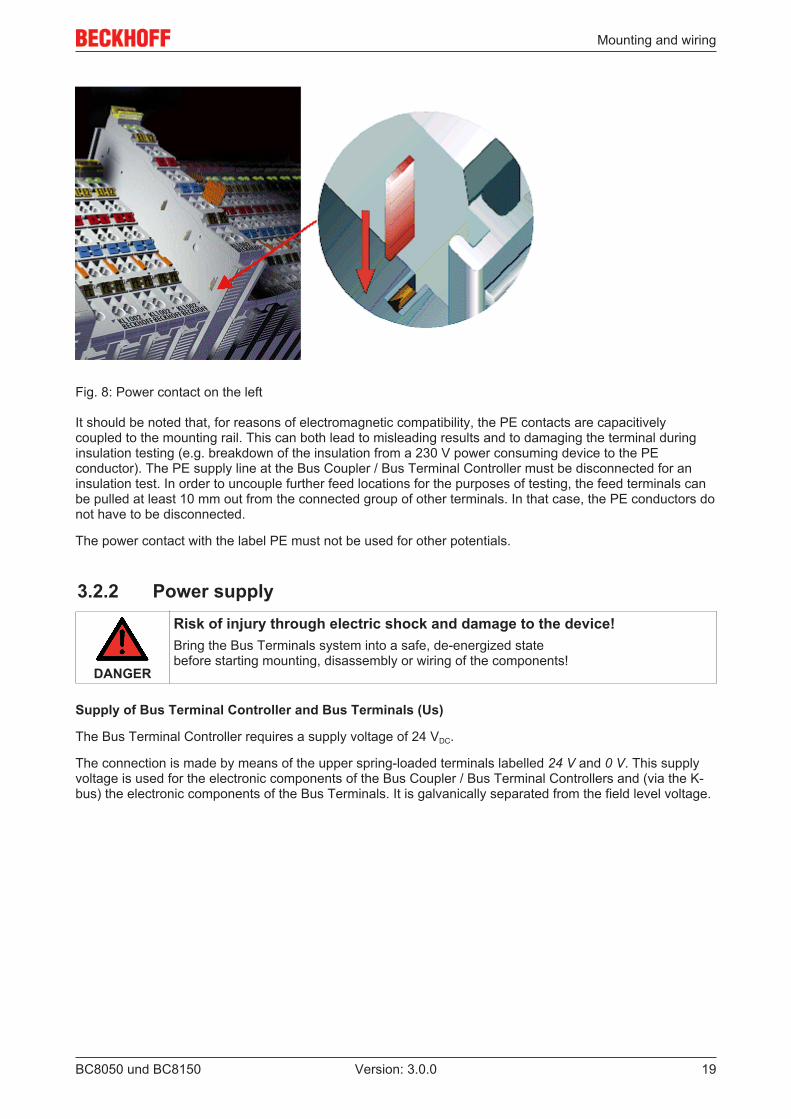
Fig. 8: Power contact on the left
It should be noted that, for reasons of electromagnetic compatibility, the PE contacts are capacitivelycoupled to the mounting rail. This can both lead to misleading results and to damaging the terminal duringinsulation testing (e.g. breakdown of the insulation from a 230 V power consuming device to the PEconductor). The PE supply line at the Bus Coupler / Bus Terminal Controller must be disconnected for aninsulation test. In order to uncouple further feed locations for the purposes of testing, the feed terminals canbe pulled at least 10 mm out from the connected group of other terminals. In that case, the PE conductors donot have to be disconnected.
The power contact with the label PE must not be used for other potentials.
3.2.2 Power supply
DANGER
Risk of injury through electric shock and damage to the device!Bring the Bus Terminals system into a safe, de-energized state before starting mounting, disassembly or wiring of the components!
Supply of Bus Terminal Controller and Bus Terminals (Us)
The Bus Terminal Controller requires a supply voltage of 24 VDC.
The connection is made by means of the upper spring-loaded terminals labelled 24 V and 0 V. This supplyvoltage is used for the electronic components of the Bus Coupler / Bus Terminal Controllers and (via the K-bus) the electronic components of the Bus Terminals. It is galvanically separated from the field level voltage.
Mounting and wiring
BC8050 und BC815020 Version: 3.0.0
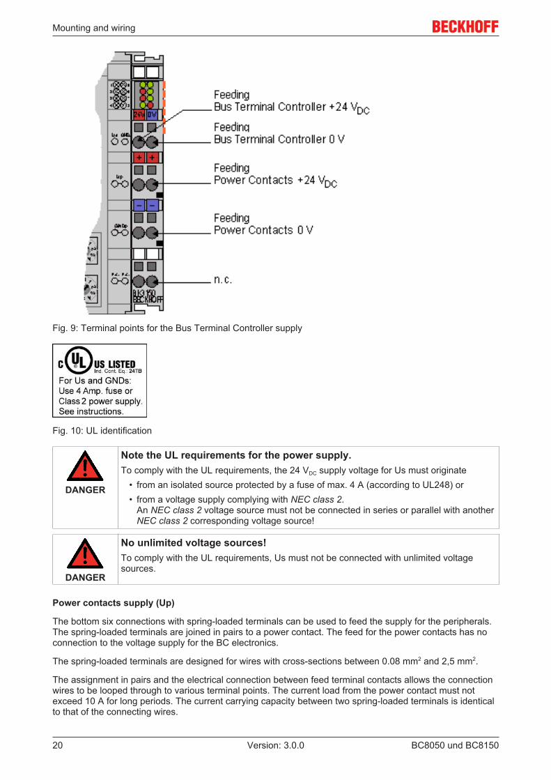
Fig. 9: Terminal points for the Bus Terminal Controller supply
Fig. 10: UL identification
DANGER
Note the UL requirements for the power supply.To comply with the UL requirements, the 24 VDC supply voltage for Us must originate
• from an isolated source protected by a fuse of max. 4 A (according to UL248) or• from a voltage supply complying with NEC class 2.
An NEC class 2 voltage source must not be connected in series or parallel with anotherNEC class 2 corresponding voltage source!
DANGER
No unlimited voltage sources!To comply with the UL requirements, Us must not be connected with unlimited voltagesources.
Power contacts supply (Up)
The bottom six connections with spring-loaded terminals can be used to feed the supply for the peripherals.The spring-loaded terminals are joined in pairs to a power contact. The feed for the power contacts has noconnection to the voltage supply for the BC electronics.
The spring-loaded terminals are designed for wires with cross-sections between 0.08 mm2 and 2,5 mm2.
The assignment in pairs and the electrical connection between feed terminal contacts allows the connectionwires to be looped through to various terminal points. The current load from the power contact must notexceed 10 A for long periods. The current carrying capacity between two spring-loaded terminals is identicalto that of the connecting wires.
Mounting and wiring
BC8050 und BC8150 21Version: 3.0.0
Power contacts
On the right hand face of the Bus Terminal Controller there are three spring contacts for the power contactconnections. The spring contacts are hidden in slots so that they cannot be accidentally touched. Byattaching a Bus Terminal the blade contacts on the left hand side of the Bus Terminal are connected to thespring contacts. The tongue and groove guides on the top and bottom of the Bus Terminal Controllers and ofthe Bus Terminals guarantees that the power contacts mate securely.
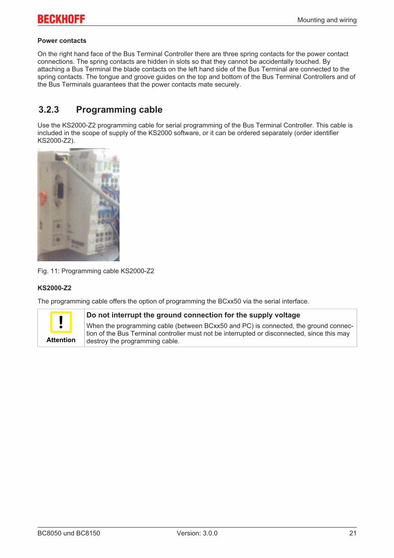
3.2.3 Programming cableUse the KS2000-Z2 programming cable for serial programming of the Bus Terminal Controller. This cable isincluded in the scope of supply of the KS2000 software, or it can be ordered separately (order identifierKS2000-Z2).
Fig. 11: Programming cable KS2000-Z2
KS2000-Z2
The programming cable offers the option of programming the BCxx50 via the serial interface.
Attention
Do not interrupt the ground connection for the supply voltageWhen the programming cable (between BCxx50 and PC) is connected, the ground connec-tion of the Bus Terminal controller must not be interrupted or disconnected, since this maydestroy the programming cable.
Mounting and wiring
BC8050 und BC815022 Version: 3.0.0
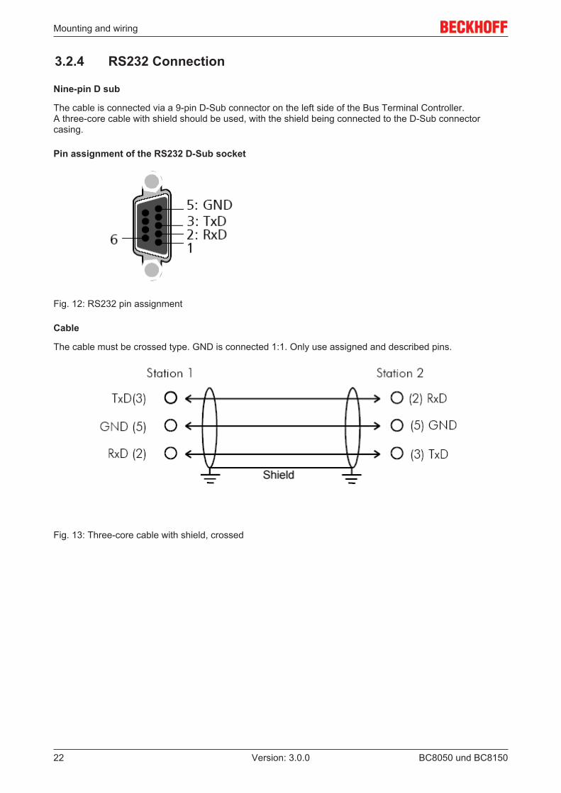
3.2.4 RS232 Connection
Nine-pin D sub
The cable is connected via a 9-pin D-Sub connector on the left side of the Bus Terminal Controller. A three-core cable with shield should be used, with the shield being connected to the D-Sub connectorcasing.
Pin assignment of the RS232 D-Sub socket
Fig. 12: RS232 pin assignment
Cable
The cable must be crossed type. GND is connected 1:1. Only use assigned and described pins.
Fig. 13: Three-core cable with shield, crossed
Mounting and wiring
BC8050 und BC8150 23Version: 3.0.0
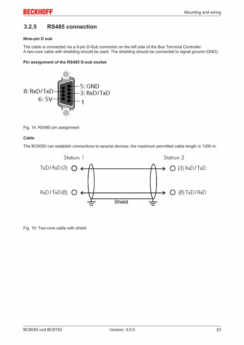
3.2.5 RS485 connection
Nine-pin D sub
The cable is connected via a 9-pin D-Sub connector on the left side of the Bus Terminal Controller. A two-core cable with shielding should be used. The shielding should be connected to signal ground (GND).
Pin assignment of the RS485 D-sub socket
Fig. 14: RS485 pin assignment
Cable
The BC8050 can establish connections to several devices; the maximum permitted cable length is 1200 m.
Fig. 15: Two-core cable with shield
Parameterization and Commissioning
BC8050 und BC815024 Version: 3.0.0
4 Parameterization and Commissioning
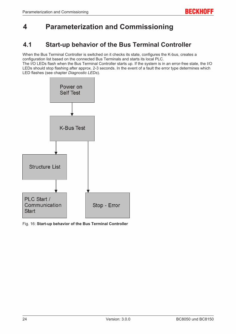
4.1 Start-up behavior of the Bus Terminal ControllerWhen the Bus Terminal Controller is switched on it checks its state, configures the K-bus, creates aconfiguration list based on the connected Bus Terminals and starts its local PLC.The I/O LEDs flash when the Bus Terminal Controller starts up. If the system is in an error-free state, the I/OLEDs should stop flashing after approx. 2-3 seconds. In the event of a fault the error type determines whichLED flashes (see chapter Diagnostic LEDs).
Fig. 16: Start-up behavior of the Bus Terminal Controller
Parameterization and Commissioning
BC8050 und BC8150 25Version: 3.0.0
4.2 Setting the AddressThe address must be set via the two rotary selection switches. The default setting is 11.
The BC8150 Bus Terminal Controller supports different protocols.
Address 1 to 39
Automatic recognition of the following protocols• Serial ADS, automatic baud rate detection, default 38400 baud, fixed data frame (8,e,1)• KS8000 protocol, automatic baud rate detection, default 38400 baud, fixed data frame (8,e,1)• KS2000 protocol, automatic baud rate detection, default 38400 baud, fixed data frame (8,e,1)• ModbusASCII protocol, automatic baud rate detection, default 38400 baud, fixed data frame (8,e,1)• TwinCAT PLC, protocol automatic baud rate detection default 38400 baud, fixed data frame (8,e,1)
Address 40 to 59• ModbusRTU, configurable baud rate, default 9600, configurable data frame default 8,n,1
Changing the address
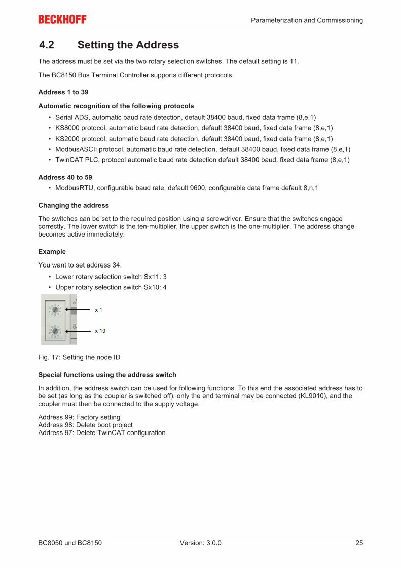
The switches can be set to the required position using a screwdriver. Ensure that the switches engagecorrectly. The lower switch is the ten-multiplier, the upper switch is the one-multiplier. The address changebecomes active immediately.
Example
You want to set address 34:
• Lower rotary selection switch Sx11: 3• Upper rotary selection switch Sx10: 4
Fig. 17: Setting the node ID
Special functions using the address switch
In addition, the address switch can be used for following functions. To this end the associated address has tobe set (as long as the coupler is switched off), only the end terminal may be connected (KL9010), and thecoupler must then be connected to the supply voltage.
Address 99: Factory settingAddress 98: Delete boot projectAddress 97: Delete TwinCAT configuration
Parameterization and Commissioning
BC8050 und BC815026 Version: 3.0.0
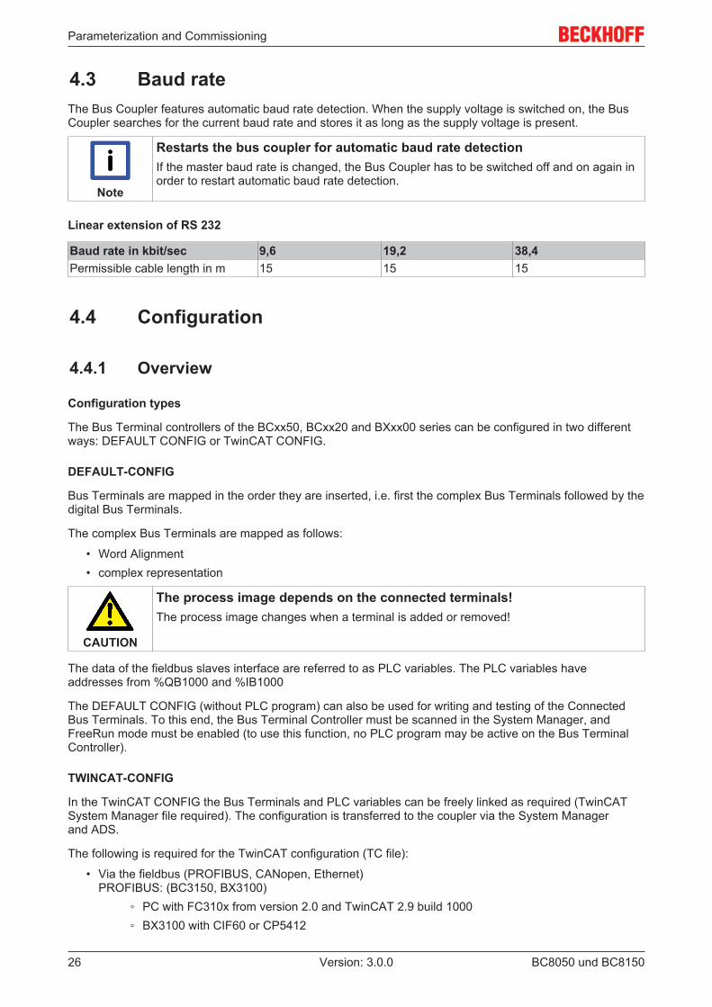
4.3 Baud rateThe Bus Coupler features automatic baud rate detection. When the supply voltage is switched on, the BusCoupler searches for the current baud rate and stores it as long as the supply voltage is present.
Note
Restarts the bus coupler for automatic baud rate detectionIf the master baud rate is changed, the Bus Coupler has to be switched off and on again inorder to restart automatic baud rate detection.
Linear extension of RS 232
Baud rate in kbit/sec 9,6 19,2 38,4Permissible cable length in m 15 15 15
4.4 Configuration
4.4.1 Overview
Configuration types
The Bus Terminal controllers of the BCxx50, BCxx20 and BXxx00 series can be configured in two differentways: DEFAULT CONFIG or TwinCAT CONFIG.
DEFAULT-CONFIG
Bus Terminals are mapped in the order they are inserted, i.e. first the complex Bus Terminals followed by thedigital Bus Terminals.
The complex Bus Terminals are mapped as follows:
• Word Alignment• complex representation
CAUTION
The process image depends on the connected terminals!The process image changes when a terminal is added or removed!
The data of the fieldbus slaves interface are referred to as PLC variables. The PLC variables haveaddresses from %QB1000 and %IB1000
The DEFAULT CONFIG (without PLC program) can also be used for writing and testing of the ConnectedBus Terminals. To this end, the Bus Terminal Controller must be scanned in the System Manager, andFreeRun mode must be enabled (to use this function, no PLC program may be active on the Bus TerminalController).
TWINCAT-CONFIG
In the TwinCAT CONFIG the Bus Terminals and PLC variables can be freely linked as required (TwinCATSystem Manager file required). The configuration is transferred to the coupler via the System Managerand ADS.
The following is required for the TwinCAT configuration (TC file):
• Via the fieldbus (PROFIBUS, CANopen, Ethernet)PROFIBUS: (BC3150, BX3100)
◦ PC with FC310x from version 2.0 and TwinCAT 2.9 build 1000◦ BX3100 with CIF60 or CP5412
Parameterization and Commissioning
BC8050 und BC8150 27Version: 3.0.0
◦ TwinCAT 2.9 build 946(NOTE: with PROFIBUS cards from Hilscher only one ADS communication is permitted, i.e.either System Manager or PLC Control)CANopen: (BC5150, BX5100)
◦ PC with FC510x from version 1.76 TwinCAT build 1030DeviceNet: (BC5250, BX5200)
◦ on requestEthernet: (BC9050, BC9020, BC9120, BX9000)
◦ PC with TwinCAT 2.10 build 1322• Via the serial ADS TwinCAT 2.9 build 1010
◦ BX3100 version 1.00◦ BX5100 version 1.00◦ BX5200 version 1.10◦ BX8000 version 1.00◦ BC3150, BC5150, BC5250, BC9050, BC9020, BC9120 from firmware B0◦ For BC8150 from TwinCAT 2.10 build 1243
BCxx50 and BXxx00 can be parameterized via the System Manager of the TwinCAT program.
• Variable I/O mapping• Type-specific PROFIBUS data (BC3150 and BX3100 only)• RTC (real-time clock) (BX series only)• SSB (Smart System Bus) (BX series only)• PLC settings• K-Bus settings
The configuration can be transferred to the BCxx50 or BXxx00 via fieldbus ADS protocol or serial ADSprotocol.
The TwinCAT configuration can be used to link variables, I/Os and data. The following is possible:
• PLC - K-BUS• PLC fieldbus (e.g. PROFIBUS slave interface to PLC)• K-bus fieldbus (only for BX controllers)• Support for TwinSAFE terminals (only BX controllers from firmware 1.17)
In addition, the TwinCAT configuration can be used to parameterize special behavior, for example whetherdata are preserved or set to "0" in the event of a fieldbus error.The real-time clock can be set via a tab in the system manager.
Work steps
1. Setting the fieldbus address2. Open the System Manager and create a TC file3. Configure fieldbus data in the TC file4. Save the TC file5. Opening a new system manager, creating a PC file and reading in saved TX file6. Creating a link to a PLC task7. Saving the configuration8. Starting the TwinCAT system9. Open the TC file in the System Manager, complete the configuration and transfer it to the BCxx50,
BCxx20 or BXxx0010. Transfer the program to BCxx50, BCxx20 or BXxx0011. Creating a boot project
Parameterization and Commissioning
BC8050 und BC815028 Version: 3.0.0
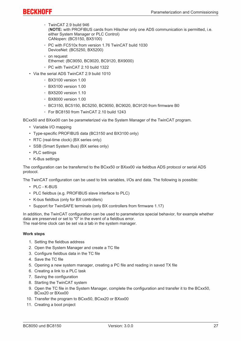
4.4.2 Creating a TwinCAT configurationIn order to configure a Bus Terminal Controller of the BCxx50, BCxx20 or BXxx00 series, create a BX file inthe System Manager. To simplify matters, files for the basic units have already been prepared. Open thecorresponding Bus Terminal Controller with New from Template.
Fig. 18: Creating a TwinCAT configuration
Select the corresponding Bus Terminal Controller.
Fig. 19: Selecting the Bus Terminal Controller
All Bus Terminal Controller components are now available:
• Fieldbus interface
• K-bus interface [} 38]• PLC Program• SSB (only Bus Terminal Controllers of the BX series)
Please refer to the relevant chapter for device configuration.
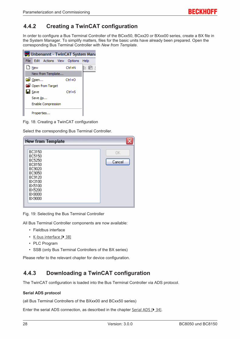
4.4.3 Downloading a TwinCAT configurationThe TwinCAT configuration is loaded into the Bus Terminal Controller via ADS protocol.
Serial ADS protocol
(all Bus Terminal Controllers of the BXxx00 and BCxx50 series)
Enter the serial ADS connection, as described in the chapter Serial ADS [} 34].
Parameterization and Commissioning
BC8050 und BC8150 29Version: 3.0.0
ADS protocol via the fieldbus
(BC3150, BC5150, BC9x20, BC9050, BX3100, BX5100, BX9000 only)
A prerequisite is that TwinCAT operates as master and is engaged in data exchange, i.e. the physical andfieldbus configuration must be complete, and data exchange must take place between the master(e.g. fieldbus master card) and the Bus Terminal Controller.
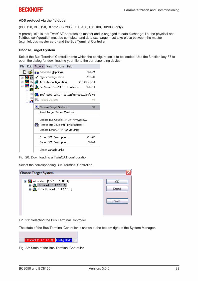
Choose Target System
Select the Bus Terminal Controller onto which the configuration is to be loaded. Use the function key F8 toopen the dialog for downloading your file to the corresponding device.
Fig. 20: Downloading a TwinCAT configuration
Select the corresponding Bus Terminal Controller.
Fig. 21: Selecting the Bus Terminal Controller
The state of the Bus Terminal Controller is shown at the bottom right of the System Manager.
Fig. 22: State of the Bus Terminal Controller
Parameterization and Commissioning
BC8050 und BC815030 Version: 3.0.0
In Config mode / FreeRun the configuration can now be downloaded to Bus Terminal Controller. If the BusTerminal Controller is in Stop mode, ADS communication is not yet activated. In this case, it is not possibleto download the configuration.
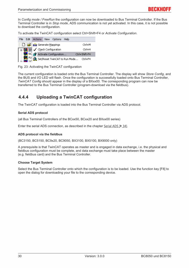
To activate the TwinCAT configuration select Ctrl+Shift+F4 or Activate Configuration.
Fig. 23: Activating the TwinCAT configuration
The current configuration is loaded onto the Bus Terminal Controller. The display will show Store Config, andthe BUS and I/O LED will flash. Once the configuration is successfully loaded onto Bus Terminal Controller,TwinCAT Config should appear in the display of a BXxx00. The corresponding program can now betransferred to the Bus Terminal Controller (program-download via the fieldbus).
4.4.4 Uploading a TwinCAT configurationThe TwinCAT configuration is loaded into the Bus Terminal Controller via ADS protocol.
Serial ADS protocol
(all Bus Terminal Controllers of the BCxx50, BCxx20 and BXxx00 series)
Enter the serial ADS connection, as described in the chapter Serial ADS [} 34].
ADS protocol via the fieldbus
(BC3150, BC5150, BC9x20, BC9050, BX3100, BX5100, BX9000 only)
A prerequisite is that TwinCAT operates as master and is engaged in data exchange, i.e. the physical andfieldbus configuration must be complete, and data exchange must take place between the master(e.g. fieldbus card) and the Bus Terminal Controller.
Choose Target System
Select the Bus Terminal Controller onto which the configuration is to be loaded. Use the function key [F8] toopen the dialog for downloading your file to the corresponding device.
Parameterization and Commissioning
BC8050 und BC8150 31Version: 3.0.0
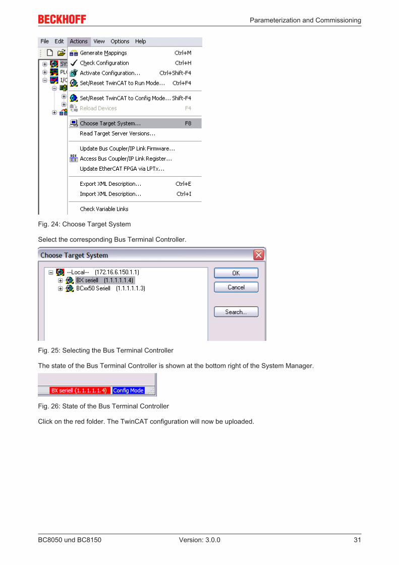
Fig. 24: Choose Target System
Select the corresponding Bus Terminal Controller.
Fig. 25: Selecting the Bus Terminal Controller
The state of the Bus Terminal Controller is shown at the bottom right of the System Manager.
Fig. 26: State of the Bus Terminal Controller
Click on the red folder. The TwinCAT configuration will now be uploaded.
Parameterization and Commissioning
BC8050 und BC815032 Version: 3.0.0
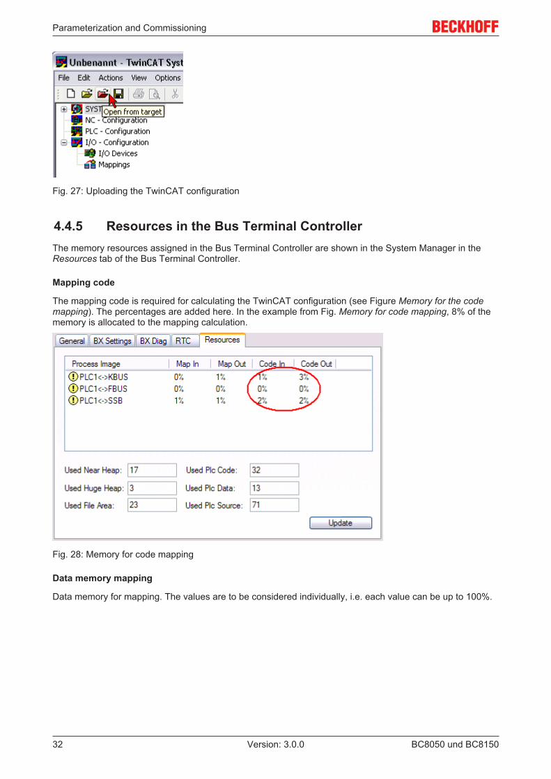
Fig. 27: Uploading the TwinCAT configuration
4.4.5 Resources in the Bus Terminal ControllerThe memory resources assigned in the Bus Terminal Controller are shown in the System Manager in theResources tab of the Bus Terminal Controller.
Mapping code
The mapping code is required for calculating the TwinCAT configuration (see Figure Memory for the codemapping). The percentages are added here. In the example from Fig. Memory for code mapping, 8% of thememory is allocated to the mapping calculation.
Fig. 28: Memory for code mapping
Data memory mapping
Data memory for mapping. The values are to be considered individually, i.e. each value can be up to 100%.
Parameterization and Commissioning
BC8050 und BC8150 33Version: 3.0.0
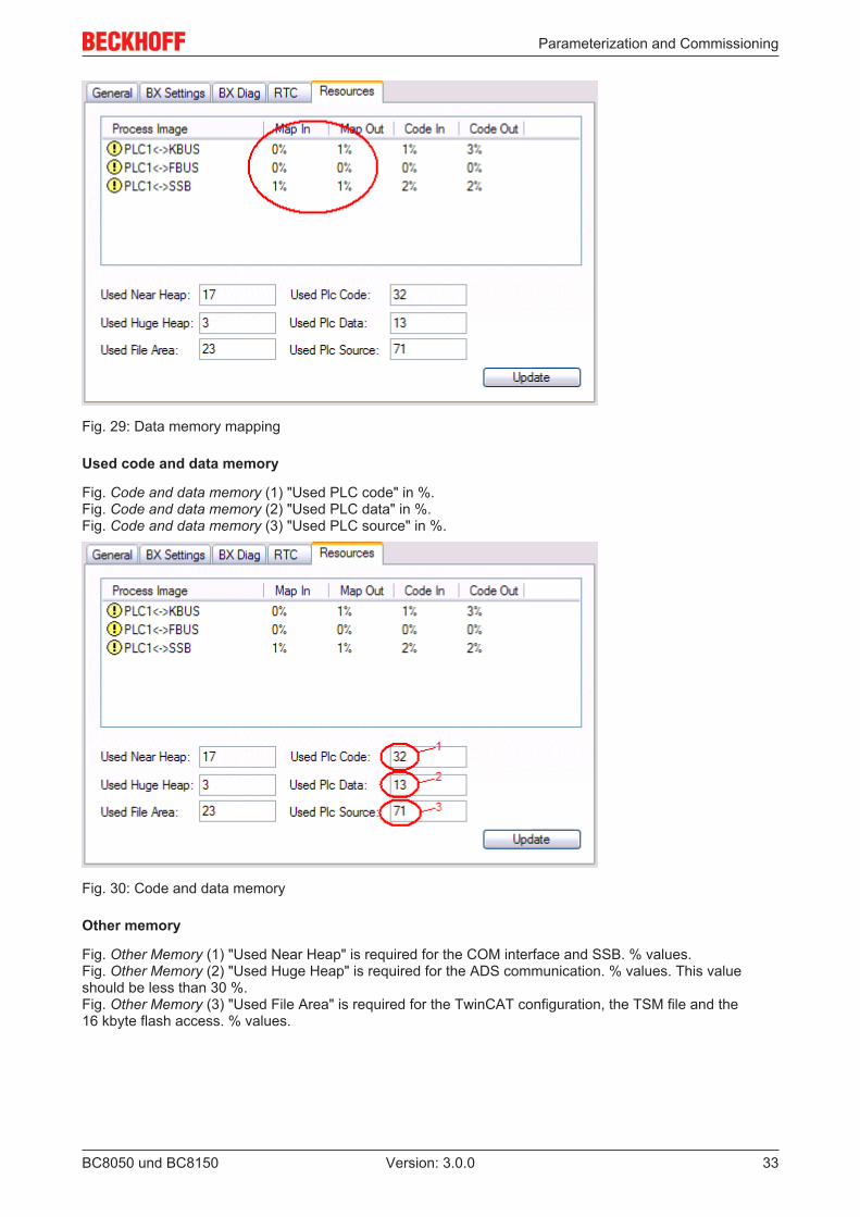
Fig. 29: Data memory mapping
Used code and data memory
Fig. Code and data memory (1) "Used PLC code" in %.Fig. Code and data memory (2) "Used PLC data" in %.Fig. Code and data memory (3) "Used PLC source" in %.
Fig. 30: Code and data memory
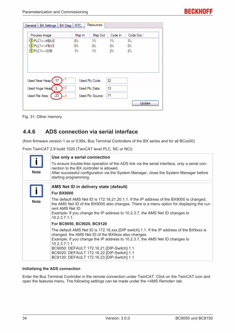
Other memory
Fig. Other Memory (1) "Used Near Heap" is required for the COM interface and SSB. % values.Fig. Other Memory (2) "Used Huge Heap" is required for the ADS communication. % values. This valueshould be less than 30 %.Fig. Other Memory (3) "Used File Area" is required for the TwinCAT configuration, the TSM file and the16 kbyte flash access. % values.
Parameterization and Commissioning
BC8050 und BC815034 Version: 3.0.0
Fig. 31: Other memory
4.4.6 ADS connection via serial interface(from firmware version 1.xx or 0.99x, Bus Terminal Controllers of the BX series and for all BCxx50)
From TwinCAT 2.9 build 1020 (TwnCAT level PLC, NC or NCI)
Note
Use only a serial connectionTo ensure trouble-free operation of the ADS link via the serial interface, only a serial con-nection to the BX controller is allowed. After successful configuration via the System Manager, close the System Manager beforestarting programming.
Note
AMS Net ID in delivery state (default)For BX9000The default AMS Net ID is 172.16.21.20.1.1. If the IP address of the BX9000 is changed,the AMS Net ID of the BX9000 also changes. There is a menu option for displaying the cur-rent AMS Net ID.Example: If you change the IP address to 10.2.3.7, the AMS Net ID changes to10.2.3.7.1.1.For BC9050, BC9020, BC9120The default AMS Net ID is 172.16.xxx.[DIP switch].1.1. If the IP address of the BX9xxx ischanged, the AMS Net ID of the BX9xxx also changes.Example: If you change the IP address to 10.2.3.7, the AMS Net ID changes to10.2.3.7.1.1.BC9050: DEFAULT 172.16.21.[DIP-Switch].1.1BC9020: DEFAULT 172.16.22.[DIP-Switch].1.1BC9120: DEFAULT 172.16.23.[DIP-Switch].1.1
Initializing the ADS connection
Enter the Bus Terminal Controller in the remote connection under TwinCAT. Click on the TwinCAT icon andopen the features menu. The following settings can be made under the >AMS Remote< tab.
Parameterization and Commissioning
BC8050 und BC8150 35Version: 3.0.0
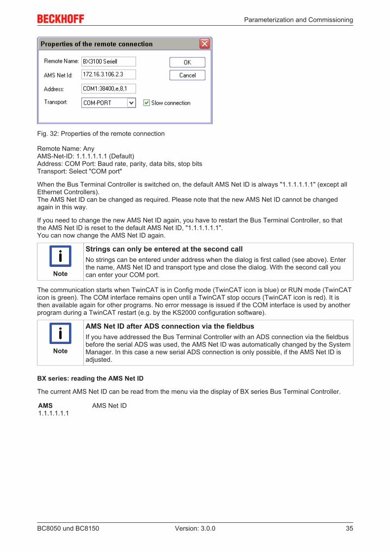
Fig. 32: Properties of the remote connection
Remote Name: AnyAMS-Net-ID: 1.1.1.1.1.1 (Default)Address: COM Port: Baud rate, parity, data bits, stop bitsTransport: Select "COM port"
When the Bus Terminal Controller is switched on, the default AMS Net ID is always "1.1.1.1.1.1" (except allEthernet Controllers).The AMS Net ID can be changed as required. Please note that the new AMS Net ID cannot be changedagain in this way.
If you need to change the new AMS Net ID again, you have to restart the Bus Terminal Controller, so thatthe AMS Net ID is reset to the default AMS Net ID, "1.1.1.1.1.1".You can now change the AMS Net ID again.
Note
Strings can only be entered at the second callNo strings can be entered under address when the dialog is first called (see above). Enterthe name, AMS Net ID and transport type and close the dialog. With the second call youcan enter your COM port.
The communication starts when TwinCAT is in Config mode (TwinCAT icon is blue) or RUN mode (TwinCATicon is green). The COM interface remains open until a TwinCAT stop occurs (TwinCAT icon is red). It isthen available again for other programs. No error message is issued if the COM interface is used by anotherprogram during a TwinCAT restart (e.g. by the KS2000 configuration software).
Note
AMS Net ID after ADS connection via the fieldbusIf you have addressed the Bus Terminal Controller with an ADS connection via the fieldbusbefore the serial ADS was used, the AMS Net ID was automatically changed by the SystemManager. In this case a new serial ADS connection is only possible, if the AMS Net ID isadjusted.
BX series: reading the AMS Net ID
The current AMS Net ID can be read from the menu via the display of BX series Bus Terminal Controller.
AMS1.1.1.1.1.1
AMS Net ID
Parameterization and Commissioning
BC8050 und BC815036 Version: 3.0.0
4.5 RS232 interface
4.5.1 TwinCAT Configuration - RS232 InterfaceTwinCAT 2.10 Build 1243 or higher is required for using the TC configuration.
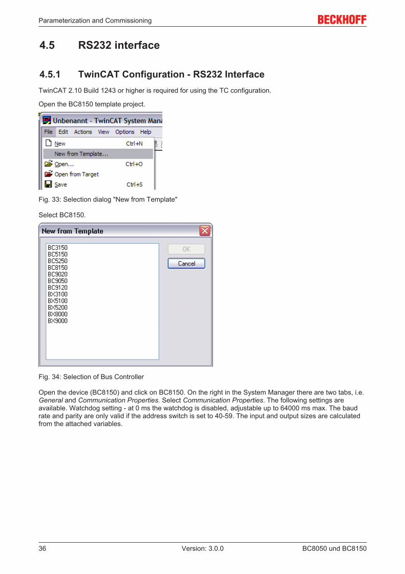
Open the BC8150 template project.
Fig. 33: Selection dialog "New from Template"
Select BC8150.
Fig. 34: Selection of Bus Controller
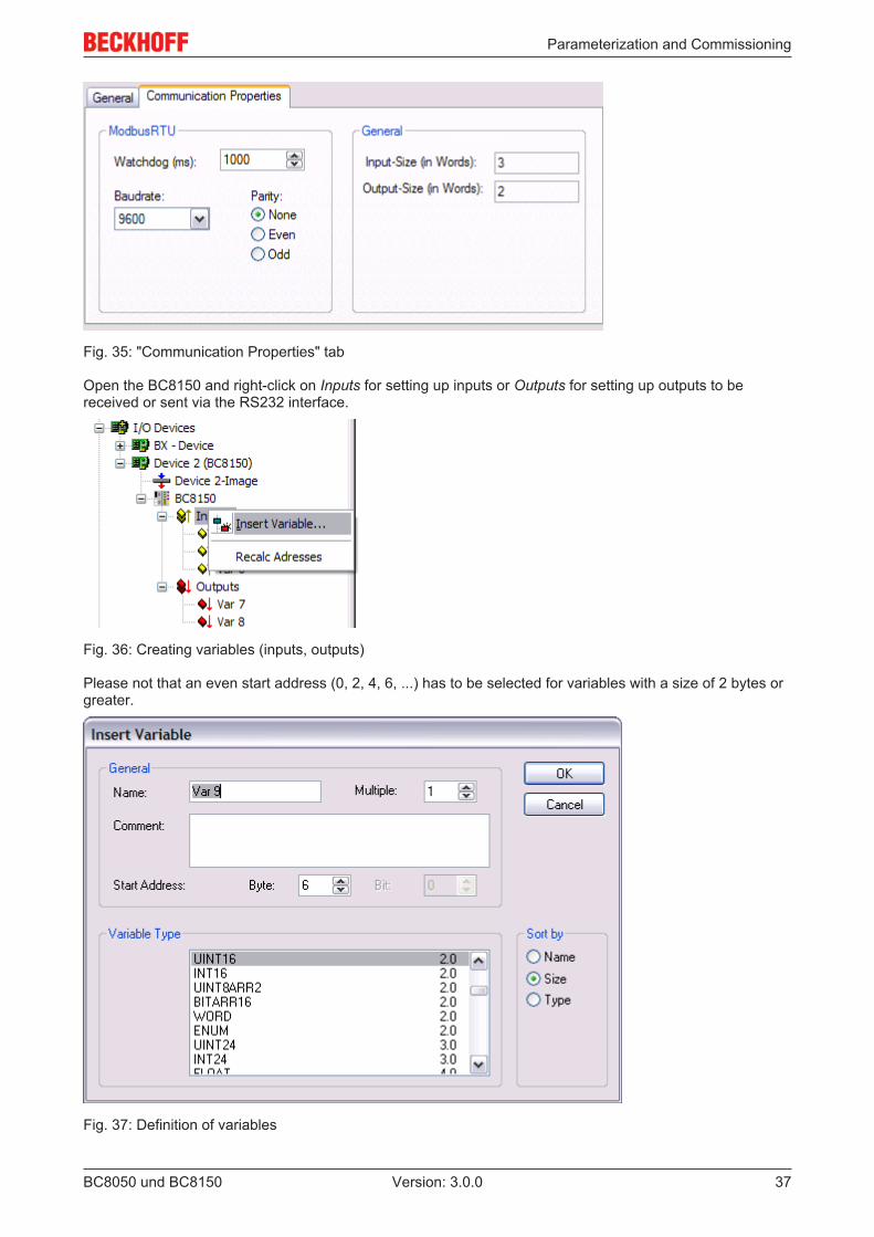
Open the device (BC8150) and click on BC8150. On the right in the System Manager there are two tabs, i.e.General and Communication Properties. Select Communication Properties. The following settings areavailable. Watchdog setting - at 0 ms the watchdog is disabled, adjustable up to 64000 ms max. The baudrate and parity are only valid if the address switch is set to 40-59. The input and output sizes are calculatedfrom the attached variables.
Parameterization and Commissioning
BC8050 und BC8150 37Version: 3.0.0
Fig. 35: "Communication Properties" tab
Open the BC8150 and right-click on Inputs for setting up inputs or Outputs for setting up outputs to bereceived or sent via the RS232 interface.
Fig. 36: Creating variables (inputs, outputs)
Please not that an even start address (0, 2, 4, 6, ...) has to be selected for variables with a size of 2 bytes orgreater.
Fig. 37: Definition of variables
Parameterization and Commissioning
BC8050 und BC815038 Version: 3.0.0
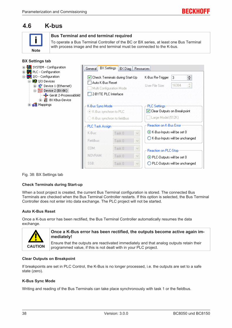
4.6 K-bus
Note
Bus Terminal and end terminal requiredTo operate a Bus Terminal Controller of the BC or BX series, at least one Bus Terminalwith process image and the end terminal must be connected to the K-bus.
BX Settings tab
Fig. 38: BX Settings tab
Check Terminals during Start-up
When a boot project is created, the current Bus Terminal configuration is stored. The connected BusTerminals are checked when the Bus Terminal Controller restarts. If this option is selected, the Bus TerminalController does not enter into data exchange. The PLC project will not be started.
Auto K-Bus Reset
Once a K-bus error has been rectified, the Bus Terminal Controller automatically resumes the dataexchange.
CAUTION
Once a K-Bus error has been rectified, the outputs become active again im-mediately!Ensure that the outputs are reactivated immediately and that analog outputs retain theirprogrammed value, if this is not dealt with in your PLC project.
Clear Outputs on Breakpoint
If breakpoints are set in PLC Control, the K-Bus is no longer processed, i.e. the outputs are set to a safestate (zero).
K-Bus Sync Mode
Writing and reading of the Bus Terminals can take place synchronously with task 1 or the fieldbus.
Parameterization and Commissioning
BC8050 und BC8150 39Version: 3.0.0
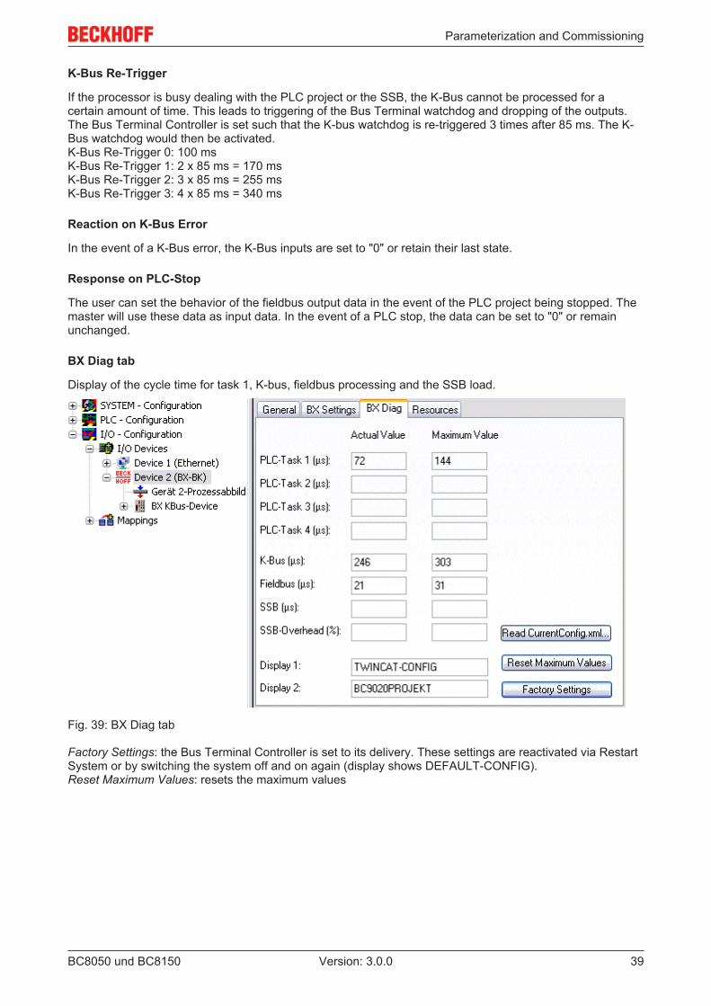
K-Bus Re-Trigger
If the processor is busy dealing with the PLC project or the SSB, the K-Bus cannot be processed for acertain amount of time. This leads to triggering of the Bus Terminal watchdog and dropping of the outputs.The Bus Terminal Controller is set such that the K-bus watchdog is re-triggered 3 times after 85 ms. The K-Bus watchdog would then be activated.K-Bus Re-Trigger 0: 100 msK-Bus Re-Trigger 1: 2 x 85 ms = 170 msK-Bus Re-Trigger 2: 3 x 85 ms = 255 msK-Bus Re-Trigger 3: 4 x 85 ms = 340 ms
Reaction on K-Bus Error
In the event of a K-Bus error, the K-Bus inputs are set to "0" or retain their last state.
Response on PLC-Stop
The user can set the behavior of the fieldbus output data in the event of the PLC project being stopped. Themaster will use these data as input data. In the event of a PLC stop, the data can be set to "0" or remainunchanged.
BX Diag tab
Display of the cycle time for task 1, K-bus, fieldbus processing and the SSB load.
Fig. 39: BX Diag tab
Factory Settings: the Bus Terminal Controller is set to its delivery. These settings are reactivated via RestartSystem or by switching the system off and on again (display shows DEFAULT-CONFIG).Reset Maximum Values: resets the maximum values
Parameterization and Commissioning
BC8050 und BC815040 Version: 3.0.0
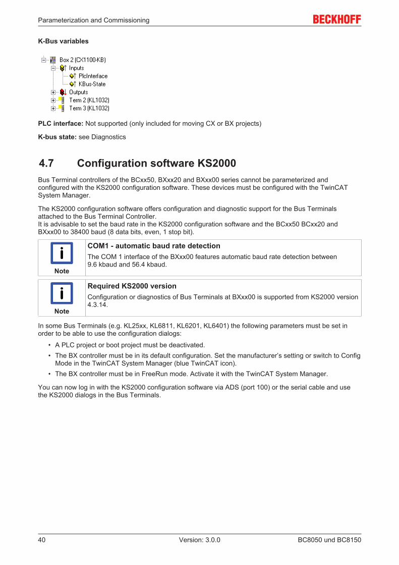
K-Bus variables
PLC interface: Not supported (only included for moving CX or BX projects)
K-bus state: see Diagnostics
4.7 Configuration software KS2000Bus Terminal controllers of the BCxx50, BXxx20 and BXxx00 series cannot be parameterized andconfigured with the KS2000 configuration software. These devices must be configured with the TwinCATSystem Manager.
The KS2000 configuration software offers configuration and diagnostic support for the Bus Terminalsattached to the Bus Terminal Controller.It is advisable to set the baud rate in the KS2000 configuration software and the BCxx50 BCxx20 andBXxx00 to 38400 baud (8 data bits, even, 1 stop bit).
Note
COM1 - automatic baud rate detectionThe COM 1 interface of the BXxx00 features automatic baud rate detection between9.6 kbaud and 56.4 kbaud.
Note
Required KS2000 versionConfiguration or diagnostics of Bus Terminals at BXxx00 is supported from KS2000 version4.3.14.
In some Bus Terminals (e.g. KL25xx, KL6811, KL6201, KL6401) the following parameters must be set inorder to be able to use the configuration dialogs:
• A PLC project or boot project must be deactivated.• The BX controller must be in its default configuration. Set the manufacturer’s setting or switch to Config
Mode in the TwinCAT System Manager (blue TwinCAT icon).• The BX controller must be in FreeRun mode. Activate it with the TwinCAT System Manager.
You can now log in with the KS2000 configuration software via ADS (port 100) or the serial cable and usethe KS2000 dialogs in the Bus Terminals.
Programming
BC8050 und BC8150 41Version: 3.0.0
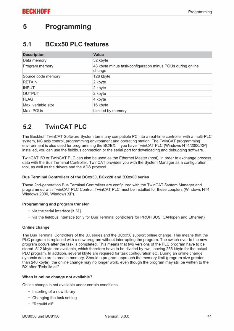
5 Programming
5.1 BCxx50 PLC featuresDescription ValueData memory 32 kbyteProgram memory 48 kbyte minus task-configuration minus POUs during online
changeSource code memory 128 kbyteRETAIN 2 kbyteINPUT 2 kbyteOUTPUT 2 kbyteFLAG 4 kbyteMax. variable size 16 kbyteMax. POUs Limited by memory
5.2 TwinCAT PLCThe Beckhoff TwinCAT Software System turns any compatible PC into a real-time controller with a multi-PLCsystem, NC axis control, programming environment and operating station. The TwinCAT programmingenvironment is also used for programming the BC/BX. If you have TwinCAT PLC (Windows NT4/2000/XP)installed, you can use the fieldbus connection or the serial port for downloading and debugging software.
TwinCAT I/O or TwinCAT PLC can also be used as the Ethernet Master (host), in order to exchange processdata with the Bus Terminal Controller. TwinCAT provides you with the System Manager as a configurationtool, as well as the drivers and the ADS protocol.
Bus Terminal Controllers of the BCxx50, BCxx20 and BXxx00 series
These 2nd-generation Bus Terminal Controllers are configured with the TwinCAT System Manager andprogrammed with TwinCAT PLC Control. TwinCAT PLC must be installed for these couplers (Windows NT4,Windows 2000, Windows XP).
Programming and program transfer• via the serial interface [} 61]• via the fieldbus interface (only for Bus Terminal controllers for PROFIBUS, CANopen and Ethernet)
Online change
The Bus Terminal Controllers of the BX series and the BCxx50 support online change. This means that thePLC program is replaced with a new program without interrupting the program. The switch-over to the newprogram occurs after the task is completed. This means that two versions of the PLC program have to bestored. 512 kbyte are available, which therefore have to be divided by two, leaving 256 kbyte for the actualPLC program. In addition, several kbyte are required for task configuration etc. During an online change,dynamic data are stored in memory. Should a program approach the memory limit (program size greaterthan 240 kbyte), the online change may no longer work, even though the program may still be written to theBX after "Rebuild all".
When is online change not available?
Online change is not available under certain conditions,.
• Inserting of a new library• Changing the task setting• "Rebuild all"
Programming
BC8050 und BC815042 Version: 3.0.0
• Controller memory limit is almost reached (PLC program greater than 90%)
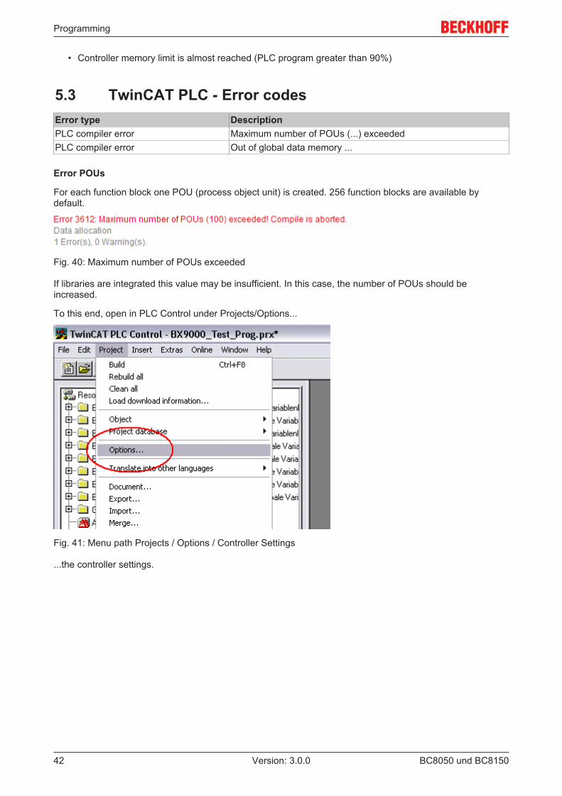
5.3 TwinCAT PLC - Error codesError type DescriptionPLC compiler error Maximum number of POUs (...) exceededPLC compiler error Out of global data memory ...
Error POUs
For each function block one POU (process object unit) is created. 256 function blocks are available bydefault.
Fig. 40: Maximum number of POUs exceeded
If libraries are integrated this value may be insufficient. In this case, the number of POUs should beincreased.
To this end, open in PLC Control under Projects/Options...
Fig. 41: Menu path Projects / Options / Controller Settings
...the controller settings.
Programming
BC8050 und BC8150 43Version: 3.0.0
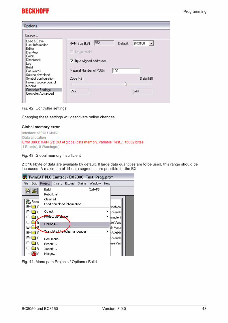
Fig. 42: Controller settings
Changing these settings will deactivate online changes.
Global memory error
Fig. 43: Global memory insufficient
2 x 16 kbyte of data are available by default. If large data quantities are to be used, this range should beincreased. A maximum of 14 data segments are possible for the BX.
Fig. 44: Menu path Projects / Options / Build
Programming
BC8050 und BC815044 Version: 3.0.0
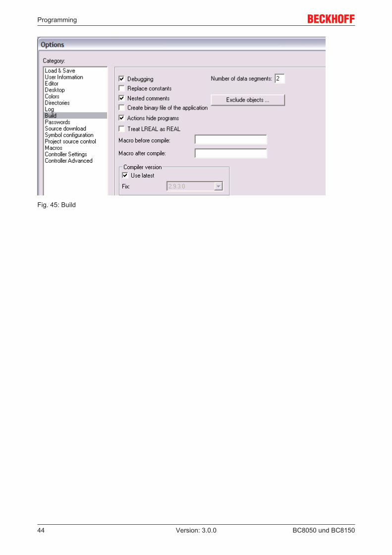
Fig. 45: Build
Programming
BC8050 und BC8150 45Version: 3.0.0
5.4 Remanent data2000 kbyte of remanent data are available for the BX controller. These data are declared as VAR RETAIN inPLC Control:
ExampleVAR RETAIN Test :BOOL; Count :INT;END_VAR
Retain data are located between VAR RETAIN and END_VAR. These data are stored in a NOVRAM andare consistent across the whole 2 kbyte range. The RETAIN data are stored in the NOVRAM after eachcycle. For 2 kbyte approx. 2 ms are required (for 1 kbyte approx. 1 ms). The variables can be configuredlocally or globally. Allocated variables (%MB, %QB, %IB) cannot be used as remanent data.
Note
Do not use VAR_RETAIN in function blocksVAR_RETAIN should not be used in function blocks. All FB data are copied into the retainmemory. This leads to an unnecessary increase in cycle time, and the retain memory isfilled with unnecessary data.
Note
Do not use variables with address as remanent dataVariables that have been assigned an address (%MB, %QB, %IB) must not be used as re-manent data.
Example for remanent data in the function block
This should be avoided, if possible, since all the data of a function block, in which even just a singleremanent bit is found, are stored by default. A program sample can be found below.
Function block test (no program code required - in ST semicolon is sufficient)FUNCTION_BLOCK TestVAR_INPUTEND_VARVAR_OUTPUTEND_VARVAREND_VARVAR_IN_OUT Counter :INT;END_VAR
MAIN programPROGRAM MAINVAR fb_Test:Test;END_VARVAR RETAIN iCounter1:INT;END_VAR
fb_Test(Counter:=iCounter1);
Programming
BC8050 und BC815046 Version: 3.0.0
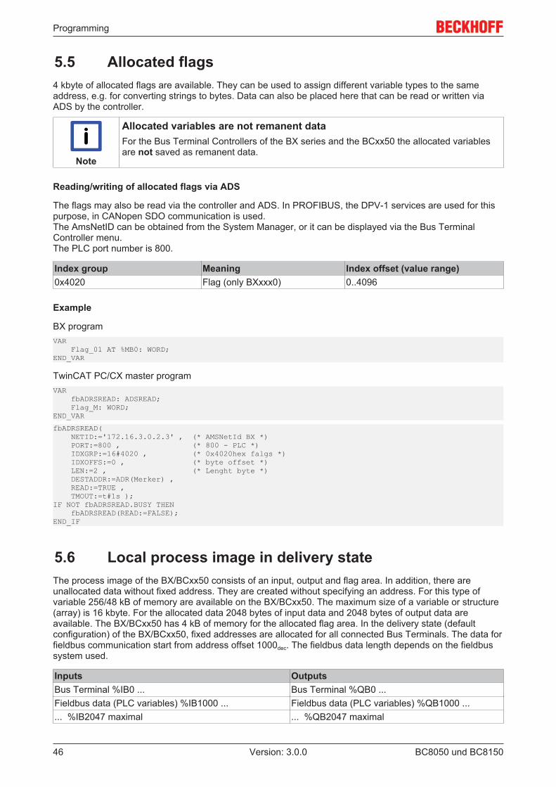
5.5 Allocated flags4 kbyte of allocated flags are available. They can be used to assign different variable types to the sameaddress, e.g. for converting strings to bytes. Data can also be placed here that can be read or written viaADS by the controller.
Note
Allocated variables are not remanent dataFor the Bus Terminal Controllers of the BX series and the BCxx50 the allocated variablesare not saved as remanent data.
Reading/writing of allocated flags via ADS
The flags may also be read via the controller and ADS. In PROFIBUS, the DPV-1 services are used for thispurpose, in CANopen SDO communication is used.The AmsNetID can be obtained from the System Manager, or it can be displayed via the Bus TerminalController menu.The PLC port number is 800.
Index group Meaning Index offset (value range)0x4020 Flag (only BXxxx0) 0..4096
Example
BX programVAR Flag_01 AT %MB0: WORD;END_VAR
TwinCAT PC/CX master programVAR fbADRSREAD: ADSREAD; Flag_M: WORD;END_VAR
fbADRSREAD( NETID:='172.16.3.0.2.3' , (* AMSNetId BX *) PORT:=800 , (* 800 - PLC *) IDXGRP:=16#4020 , (* 0x4020hex falgs *) IDXOFFS:=0 , (* byte offset *) LEN:=2 , (* Lenght byte *) DESTADDR:=ADR(Merker) , READ:=TRUE , TMOUT:=t#1s );IF NOT fbADRSREAD.BUSY THEN fbADRSREAD(READ:=FALSE);END_IF
5.6 Local process image in delivery stateThe process image of the BX/BCxx50 consists of an input, output and flag area. In addition, there areunallocated data without fixed address. They are created without specifying an address. For this type ofvariable 256/48 kB of memory are available on the BX/BCxx50. The maximum size of a variable or structure(array) is 16 kbyte. For the allocated data 2048 bytes of input data and 2048 bytes of output data areavailable. The BX/BCxx50 has 4 kB of memory for the allocated flag area. In the delivery state (defaultconfiguration) of the BX/BCxx50, fixed addresses are allocated for all connected Bus Terminals. The data forfieldbus communication start from address offset 1000dec. The fieldbus data length depends on the fieldbussystem used.
Inputs OutputsBus Terminal %IB0 ... Bus Terminal %QB0 ...Fieldbus data (PLC variables) %IB1000 ... Fieldbus data (PLC variables) %QB1000 ...... %IB2047 maximal ... %QB2047 maximal
Programming
BC8050 und BC8150 47Version: 3.0.0
Differences in the protocols
The data for the higher-level master, Modbus or KS8000 protocol are stored in the BC8150 from address1000. For Modbus the maximum data length is 512 bytes and does not have to be set within the range 1 to126 words. For the KS8000 protocol the number of data from address 1000 is preset to 8 words or 16 bytesinputs and 8 words or 16 bytes outputs. The BC8150 will reject data telegrams that do not match this numberexactly and issue an error. This data length can be parameterized via a function block in the BC8150.
If the Modbus protocol is used, data access to the BC8150 flag area is recommended. This area can be readand or written to without triggering the watchdog. The ADS protocol can access all data. The whole processimage can be accessed via port 800, and the process image from address 1000 via port 300. If port address800 is used, the data are only available for read access. If the serial ADS is used, it is recommended toaccess the flag area that can be reached via port 800 and IndexGroup 0x4020.
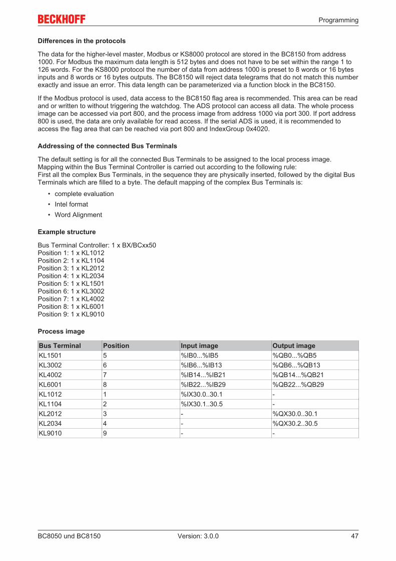
Addressing of the connected Bus Terminals
The default setting is for all the connected Bus Terminals to be assigned to the local process image.Mapping within the Bus Terminal Controller is carried out according to the following rule:First all the complex Bus Terminals, in the sequence they are physically inserted, followed by the digital BusTerminals which are filled to a byte. The default mapping of the complex Bus Terminals is:
• complete evaluation• Intel format• Word Alignment
Example structure
Bus Terminal Controller: 1 x BX/BCxx50Position 1: 1 x KL1012Position 2: 1 x KL1104Position 3: 1 x KL2012Position 4: 1 x KL2034Position 5: 1 x KL1501Position 6: 1 x KL3002Position 7: 1 x KL4002Position 8: 1 x KL6001Position 9: 1 x KL9010
Process image
Bus Terminal Position Input image Output imageKL1501 5 %IB0...%IB5 %QB0...%QB5KL3002 6 %IB6...%IB13 %QB6...%QB13KL4002 7 %IB14...%IB21 %QB14...%QB21KL6001 8 %IB22...%IB29 %QB22...%QB29KL1012 1 %IX30.0..30.1 -KL1104 2 %IX30.1..30.5 -KL2012 3 - %QX30.0..30.1KL2034 4 - %QX30.2..30.5KL9010 9 - -
Programming
BC8050 und BC815048 Version: 3.0.0
Note
Show associated variablesIf you do not know the address of the Bus Terminals that you have assigned to the localPLC (BX/BCxx50):Perform your hardware configuration in the System Manager. After you have entered all theBus Terminals and PLC variables, click with the right mouse button on the BX/BCxx50 inthe hardware tree, and select the menu item Export variables information.... A file is saved,and this file can be inserted in the System Manager under Project - Import. Now you willhave the entry TwinCAT import under the global variables, and you will find here all thevariables that you have assigned to the local PLC (BX/BCxx50).
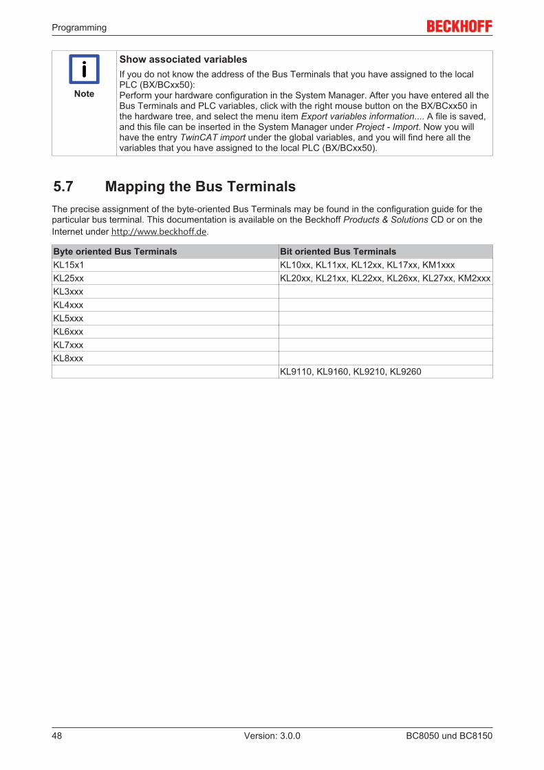
5.7 Mapping the Bus TerminalsThe precise assignment of the byte-oriented Bus Terminals may be found in the configuration guide for theparticular bus terminal. This documentation is available on the Beckhoff Products & Solutions CD or on theInternet under http://www.beckhoff.de.
Byte oriented Bus Terminals Bit oriented Bus TerminalsKL15x1 KL10xx, KL11xx, KL12xx, KL17xx, KM1xxxKL25xx KL20xx, KL21xx, KL22xx, KL26xx, KL27xx, KM2xxxKL3xxxKL4xxxKL5xxxKL6xxxKL7xxxKL8xxx
KL9110, KL9160, KL9210, KL9260
Programming
BC8050 und BC8150 49Version: 3.0.0
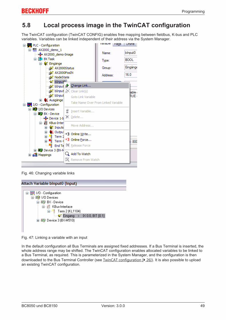
5.8 Local process image in the TwinCAT configurationThe TwinCAT configuration (TwinCAT CONFIG) enables free mapping between fieldbus, K-bus and PLCvariables. Variables can be linked independent of their address via the System Manager.
Fig. 46: Changing variable links
Fig. 47: Linking a variable with an input
In the default configuration all Bus Terminals are assigned fixed addresses. If a Bus Terminal is inserted, thewhole address range may be shifted. The TwinCAT configuration enables allocated variables to be linked toa Bus Terminal, as required. This is parameterized in the System Manager, and the configuration is thendownloaded to the Bus Terminal Controller (see TwinCAT configuration [} 26]). It is also possible to uploadan existing TwinCAT configuration.
Programming
BC8050 und BC815050 Version: 3.0.0
5.9 Creating a boot projectThe following memory resources are available for generating the boot project
• approx. 250 kbyte flash on the Bus Terminal controllers of the BX series;• approx. 48 kbyte flash on the Bus Terminal controllers of the BCxx50 series.
PLC Control
After logging into TwinCAT PLC Control, a boot project can be created.
• Opening a PLC project• Selecting the target system (or selection the serial interface)• Logging into the BX/BCxx50• Creating a boot project (Online\Create boot project)
The PLC LED lights up green once a valid boot project is available on the BX/BCxx50.
In the Bus Terminal controllers of the BX series, the PLC LED flashes orange while boot project is created.The PLC LED lights up orange if no boot project is available on the BX.
Deleting a boot project
The boot project can be deleted from the Bus Terminal Controller. The following steps must be followed:
• Opening the project• Logging into the Bus Terminal Controller• Deleting the boot project (Online\Delete boot project)
The PLC LED lights up orange when the boot project is deleted.
Note
Using the current project as boot projectAfter an online change the old project is still shown as boot project. To use the currentproject (after the online change) as the boot project, the boot project has to be recreated.
Bypassing the start of the boot project*
With the Bus Terminal controllers of the BX series, starting of the boot project during booting can beprevented by pressing the Navi button. This does not delete the boot project. The project is reloaded whenthe Bus Terminal Controller is rebooted.
* from version 0.85
5.10 Communication between TwinCAT and BX/BCxx50For transferring data from TwinCAT to the Bus Terminal Controller, it makes sense to organize the data in astructure. Please note the following to account for the differences in data management on the two systems.
• If two different data types are sent in sequence (e.g. byte and INT), the following variable is set to thenext even address offset
• Boolean variables should never be allocated individually within a structure, since they would invariablyoccupy 1 byte. Boolean expressions should always be masked in a byte or word.
Example 1: A structure on the BX/BCxx50 and on the PC
Variable BX/BCxx50 memory PC memory (TwinCAT)Byte %..B0 %..B0INT (1) %..B2 %..B1INT (2) %..B4 %..B3
Programming
BC8050 und BC8150 51Version: 3.0.0
Due to the fact that another variable type (INT) follows the first byte, in the BX/BCxx50 it was assigned thenext free even address. In order to achieve the same data structure on both systems, a dummy byte has tobe inserted in the PC project (see example 2).
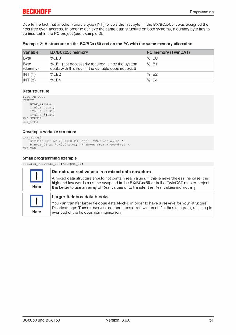
Example 2: A structure on the BX/BCxx50 and on the PC with the same memory allocation
Variable BX/BCxx50 memory PC memory (TwinCAT)Byte %..B0 %..B0Byte(dummy)
%..B1 (not necessarily required, since the systemdeals with this itself if the variable does not exist)
%..B1
INT (1) %..B2 %..B2INT (2) %..B4 %..B4
Data structureType PB_DataSTRUCT wVar_1:WORD; iValue_1:INT; iValue_2:INT; iValue_3:INT;END_STRUCTEND_TYPE
Creating a variable structureVAR_Global strData_Out AT %QB1000:PB_Data; (*PLC Variables *) bInput_01 AT %IX0.0:BOOL; (* Input from a terminal *)END_VAR
Small programming examplestrData_Out.wVar_1.0:=bInput_01;
Note
Do not use real values in a mixed data structureA mixed data structure should not contain real values. If this is nevertheless the case, thehigh and low words must be swapped in the BX/BCxx50 or in the TwinCAT master project.It is better to use an array of Real values or to transfer the Real values individually.
Note
Larger fieldbus data blocksYou can transfer larger fieldbus data blocks, in order to have a reserve for your structure.Disadvantage: These reserves are then transferred with each fieldbus telegram, resulting inoverload of the fieldbus communication.
Programming
BC8050 und BC815052 Version: 3.0.0
5.11 Up- and downloading of programsThe Bus Terminal Controller has a memory for the source code. It can be used for storing the program, thetask configuration, and the libraries. Should the memory be insufficient, the source code may be storedwithout task configuration and libraries. This takes up significant less memory space!
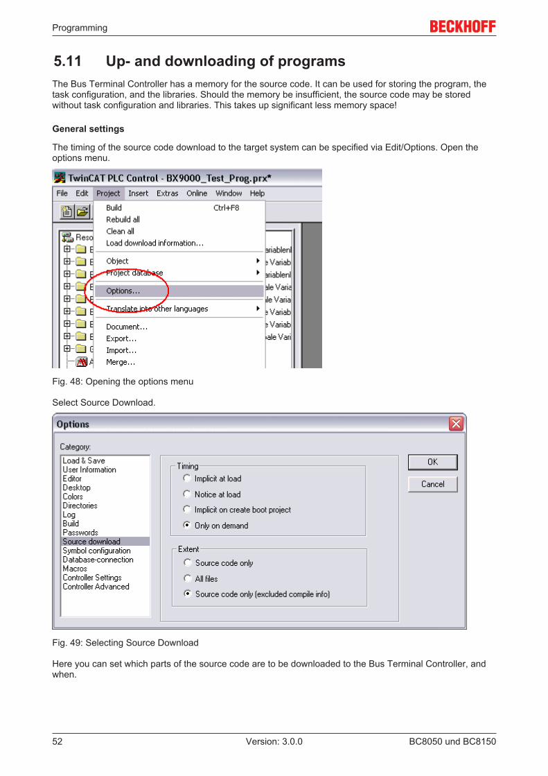
General settings
The timing of the source code download to the target system can be specified via Edit/Options. Open theoptions menu.
Fig. 48: Opening the options menu
Select Source Download.
Fig. 49: Selecting Source Download
Here you can set which parts of the source code are to be downloaded to the Bus Terminal Controller, andwhen.
Programming
BC8050 und BC8150 53Version: 3.0.0
Source code only: the prx file with information on the online change is transferred. Login via online changeis possible (the PLC does not stop).All files: as Source code only, plus all required libraries.Source code only (compile info excluded): only the prx file is transferred. Login is only possible when thePLC stops.
Which option you can use depends on the size of your projects.
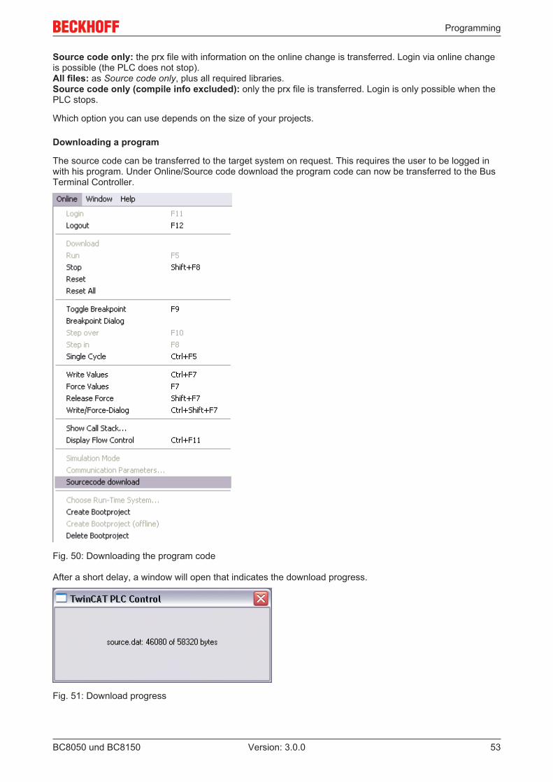
Downloading a program
The source code can be transferred to the target system on request. This requires the user to be logged inwith his program. Under Online/Source code download the program code can now be transferred to the BusTerminal Controller.
Fig. 50: Downloading the program code
After a short delay, a window will open that indicates the download progress.
Fig. 51: Download progress
Programming
BC8050 und BC815054 Version: 3.0.0
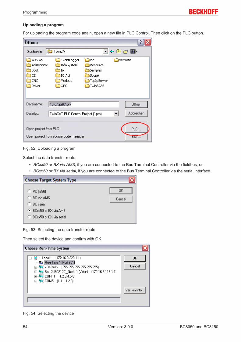
Uploading a program
For uploading the program code again, open a new file in PLC Control. Then click on the PLC button.
Fig. 52: Uploading a program
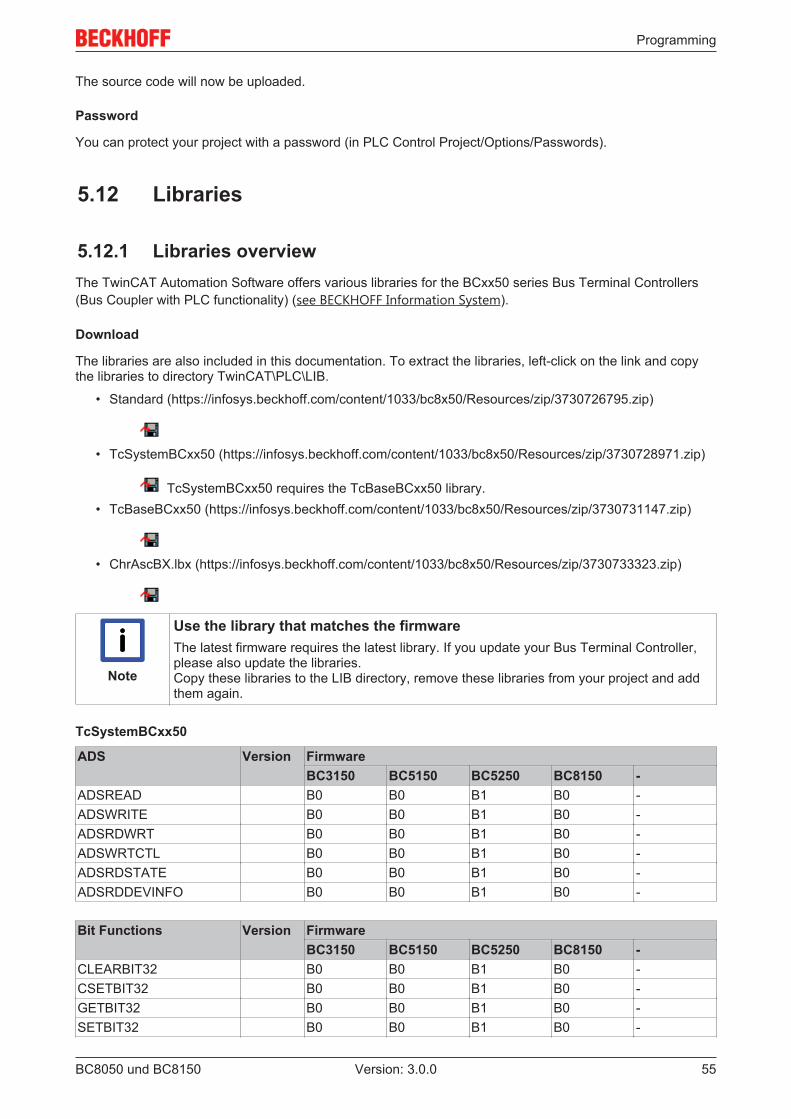
Select the data transfer route:
• BCxx50 or BX via AMS, if you are connected to the Bus Terminal Controller via the fieldbus, or• BCxx50 or BX via serial, if you are connected to the Bus Terminal Controller via the serial interface.
Fig. 53: Selecting the data transfer route
Then select the device and confirm with OK.
Fig. 54: Selecting the device
Programming
BC8050 und BC8150 55Version: 3.0.0
The source code will now be uploaded.
Password
You can protect your project with a password (in PLC Control Project/Options/Passwords).
5.12 Libraries
5.12.1 Libraries overviewThe TwinCAT Automation Software offers various libraries for the BCxx50 series Bus Terminal Controllers(Bus Coupler with PLC functionality) (see BECKHOFF Information System).
Download
The libraries are also included in this documentation. To extract the libraries, left-click on the link and copythe libraries to directory TwinCAT\PLC\LIB.
• Standard (https://infosys.beckhoff.com/content/1033/bc8x50/Resources/zip/3730726795.zip)
• TcSystemBCxx50 (https://infosys.beckhoff.com/content/1033/bc8x50/Resources/zip/3730728971.zip)
TcSystemBCxx50 requires the TcBaseBCxx50 library.• TcBaseBCxx50 (https://infosys.beckhoff.com/content/1033/bc8x50/Resources/zip/3730731147.zip)
• ChrAscBX.lbx (https://infosys.beckhoff.com/content/1033/bc8x50/Resources/zip/3730733323.zip)
Note
Use the library that matches the firmwareThe latest firmware requires the latest library. If you update your Bus Terminal Controller,please also update the libraries.Copy these libraries to the LIB directory, remove these libraries from your project and addthem again.
TcSystemBCxx50
ADS Version FirmwareBC3150 BC5150 BC5250 BC8150 -
ADSREAD B0 B0 B1 B0 -ADSWRITE B0 B0 B1 B0 -ADSRDWRT B0 B0 B1 B0 -ADSWRTCTL B0 B0 B1 B0 -ADSRDSTATE B0 B0 B1 B0 -ADSRDDEVINFO B0 B0 B1 B0 -
Bit Functions Version FirmwareBC3150 BC5150 BC5250 BC8150 -
CLEARBIT32 B0 B0 B1 B0 -CSETBIT32 B0 B0 B1 B0 -GETBIT32 B0 B0 B1 B0 -SETBIT32 B0 B0 B1 B0 -
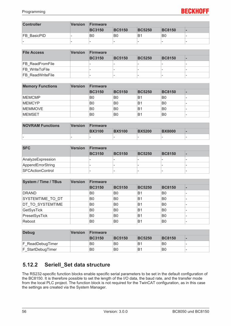
Programming
BC8050 und BC815056 Version: 3.0.0
Controller Version FirmwareBC3150 BC5150 BC5250 BC8150 -
FB_BasicPID - B0 B0 B1 B0 -- - - - - - -
File Access Version FirmwareBC3150 BC5150 BC5250 BC8150 -
FB_ReadFromFile - - - - -FB_WriteToFile - - - - -FB_ReadWriteFile - - - - -
Memory Functions Version FirmwareBC3150 BC5150 BC5250 BC8150 -
MEMCMP B0 B0 B1 B0 -MEMCYP B0 B0 B1 B0 -MEMMOVE B0 B0 B1 B0 -MEMSET B0 B0 B1 B0 -
NOVRAM Functions Version FirmwareBX3100 BX5100 BX5200 BX8000 -
- - - - - - -
SFC Version FirmwareBC3150 BC5150 BC5250 BC8150 -
AnalyzeExpression - - - - -AppendErrorString - - - - -SFCActionControl - - - - -
System / Time / TBus Version FirmwareBC3150 BC5150 BC5250 BC8150 -
DRAND B0 B0 B1 B0 -SYSTEMTIME_TO_DT B0 B0 B1 B0 -DT_TO_SYSTEMTIME B0 B0 B1 B0 -GetSysTick B0 B0 B1 B0 -PresetSysTick B0 B0 B1 B0 -Reboot B0 B0 B1 B0 -
Debug Version FirmwareBC3150 BC5150 BC5250 BC8150 -
F_ReadDebugTimer B0 B0 B1 B0 -F_StartDebugTimer B0 B0 B1 B0 -
5.12.2 Seriell_Set data structureThe RS232-specific function blocks enable specific serial parameters to be set in the default configuration ofthe BC8150. It is therefore possible to set the length of the I/O data, the baud rate, and the transfer modefrom the local PLC project. The function block is not required for the TwinCAT configuration, as in this casethe settings are created via the System Manager.
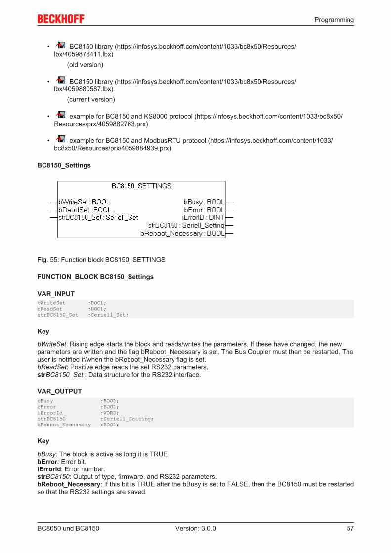
Programming
BC8050 und BC8150 57Version: 3.0.0
• BC8150 library (https://infosys.beckhoff.com/content/1033/bc8x50/Resources/lbx/4059878411.lbx)
(old version)
• BC8150 library (https://infosys.beckhoff.com/content/1033/bc8x50/Resources/lbx/4059880587.lbx)
(current version)
• example for BC8150 and KS8000 protocol (https://infosys.beckhoff.com/content/1033/bc8x50/Resources/prx/4059882763.prx)
• example for BC8150 and ModbusRTU protocol (https://infosys.beckhoff.com/content/1033/bc8x50/Resources/prx/4059884939.prx)
BC8150_Settings
Fig. 55: Function block BC8150_SETTINGS
FUNCTION_BLOCK BC8150_Settings
VAR_INPUTbWriteSet :BOOL;bReadSet :BOOL;strBC8150_Set :Seriell_Set;
Key
bWriteSet: Rising edge starts the block and reads/writes the parameters. If these have changed, the newparameters are written and the flag bReboot_Necessary is set. The Bus Coupler must then be restarted. Theuser is notified if/when the bReboot_Necessary flag is set.bReadSet: Positive edge reads the set RS232 parameters.strBC8150_Set : Data structure for the RS232 interface.
VAR_OUTPUTbBusy :BOOL;bError :BOOL;iErrorId :WORD;strBC8150 :Seriell_Setting;bReboot_Necessary :BOOL;
Key
bBusy: The block is active as long it is TRUE.bError: Error bit.iErrorId: Error number.strBC8150: Output of type, firmware, and RS232 parameters.bReboot_Necessary: If this bit is TRUE after the bBusy is set to FALSE, then the BC8150 must be restartedso that the RS232 settings are saved.
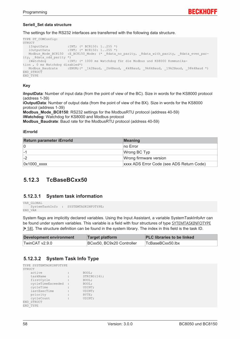
Programming
BC8050 und BC815058 Version: 3.0.0
Seriell_Set data structure
The settings for the RS232 interfaces are transferred with the following data structure.TYPE ST_COMConfig:STRUCT iInputData :INT; (* BC8150: 1..255 *) iOutputData :INT; (* BC8150: 1..255 *) Modbus_Mode_BC8150 :E_BC8150_Mode; (* _8data_no_parity, _8data_with_parity, _8data_even_par-ity, _8data_odd_parity *) iWatchdog :INT; (* 1000 ms Watchdog für die Modbus und KS8000 Kommunika-tion , 0 ms Watchdog disabled*) Modbus_Baudrate :ENUM;(* _1k2Baud, _2k4Baud, _4k8Baud, _9k6kBaud, _19k2Baud, _38k4Baud *)END_STRUCTEND_TYPE
Key
iInputData: Number of input data (from the point of view of the BC). Size in words for the KS8000 protocol(address 1-39)iOutputData: Number of output data (from the point of view of the BX). Size in words for the KS8000protocol (address 1-39)Modbus_Mode_BC8150: RS232 settings for the ModbusRTU protocol (address 40-59)iWatchdog: Watchdog for KS8000 and Modbus protocolModbus_Baudrate: Baud rate for the ModbusRTU protocol (address 40-59)
iErrorId
Return parameter iErrorId Meaning0 no Error-1 Wrong BC Typ-2 Wrong firmware version0x1000_xxxx xxxx ADS Error Code (see ADS Return Code)
5.12.3 TcBaseBCxx50
5.12.3.1 System task informationVAR_GLOBAL SystemTaskInfo : SYSTEMTASKINFOTYPE;END_VAR
System flags are implicitly declared variables. Using the Input Assistant, a variable SystemTaskInfoArr canbe found under system variables. This variable is a field with four structures of type SYTEMTASKINFOTYPE[} 58]. The structure definition can be found in the system library. The index in this field is the task ID.
Development environment Target platform PLC libraries to be linkedTwinCAT v2.9.0 BCxx50, BC9x20 Controller TcBaseBCxx50.lbx
5.12.3.2 System Task Info TypeTYPE SYSTEMTASKINFOTYPESTRUCT active : BOOL; taskName : STRING(16); firstCycle : BOOL; cycleTimeExceeded : BOOL; cycleTime : UDINT; lastExecTime : UDINT; priority : BYTE; cycleCount : UDINT;END_STRUCTEND_TYPE
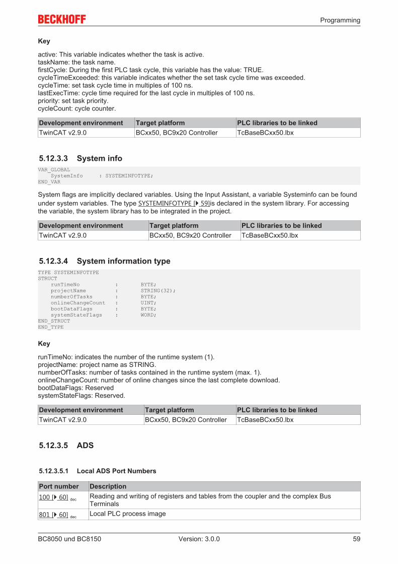
Programming
BC8050 und BC8150 59Version: 3.0.0
Key
active: This variable indicates whether the task is active.taskName: the task name.firstCycle: During the first PLC task cycle, this variable has the value: TRUE.cycleTimeExceeded: this variable indicates whether the set task cycle time was exceeded.cycleTime: set task cycle time in multiples of 100 ns.lastExecTime: cycle time required for the last cycle in multiples of 100 ns.priority: set task priority.cycleCount: cycle counter.
Development environment Target platform PLC libraries to be linkedTwinCAT v2.9.0 BCxx50, BC9x20 Controller TcBaseBCxx50.lbx
5.12.3.3 System infoVAR_GLOBAL SystemInfo : SYSTEMINFOTYPE;END_VAR
System flags are implicitly declared variables. Using the Input Assistant, a variable Systeminfo can be foundunder system variables. The type SYSTEMINFOTYPE [} 59]is declared in the system library. For accessingthe variable, the system library has to be integrated in the project.
Development environment Target platform PLC libraries to be linkedTwinCAT v2.9.0 BCxx50, BC9x20 Controller TcBaseBCxx50.lbx
5.12.3.4 System information typeTYPE SYSTEMINFOTYPESTRUCT runTimeNo : BYTE; projectName : STRING(32); numberOfTasks : BYTE; onlineChangeCount : UINT; bootDataFlags : BYTE; systemStateFlags : WORD;END_STRUCTEND_TYPE
Key
runTimeNo: indicates the number of the runtime system (1).projectName: project name as STRING.numberOfTasks: number of tasks contained in the runtime system (max. 1).onlineChangeCount: number of online changes since the last complete download.bootDataFlags: ReservedsystemStateFlags: Reserved.
Development environment Target platform PLC libraries to be linkedTwinCAT v2.9.0 BCxx50, BC9x20 Controller TcBaseBCxx50.lbx
5.12.3.5 ADS
5.12.3.5.1 Local ADS Port Numbers
Port number Description100 [} 60] dec Reading and writing of registers and tables from the coupler and the complex Bus
Terminals801 [} 60] dec Local PLC process image
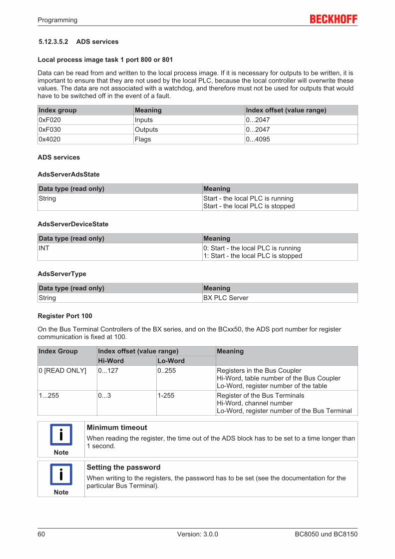
Programming
BC8050 und BC815060 Version: 3.0.0
5.12.3.5.2 ADS services
Local process image task 1 port 800 or 801
Data can be read from and written to the local process image. If it is necessary for outputs to be written, it isimportant to ensure that they are not used by the local PLC, because the local controller will overwrite thesevalues. The data are not associated with a watchdog, and therefore must not be used for outputs that wouldhave to be switched off in the event of a fault.
Index group Meaning Index offset (value range)0xF020 Inputs 0...20470xF030 Outputs 0...20470x4020 Flags 0...4095
ADS services
AdsServerAdsState
Data type (read only) MeaningString Start - the local PLC is running
Start - the local PLC is stopped
AdsServerDeviceState
Data type (read only) MeaningINT 0: Start - the local PLC is running
1: Start - the local PLC is stopped
AdsServerType
Data type (read only) MeaningString BX PLC Server
Register Port 100
On the Bus Terminal Controllers of the BX series, and on the BCxx50, the ADS port number for registercommunication is fixed at 100.
Index Group Index offset (value range) MeaningHi-Word Lo-Word
0 [READ ONLY] 0...127 0..255 Registers in the Bus CouplerHi-Word, table number of the Bus CouplerLo-Word, register number of the table
1...255 0...3 1-255 Register of the Bus TerminalsHi-Word, channel numberLo-Word, register number of the Bus Terminal
Note
Minimum timeoutWhen reading the register, the time out of the ADS block has to be set to a time longer than1 second.
Note
Setting the passwordWhen writing to the registers, the password has to be set (see the documentation for theparticular Bus Terminal).
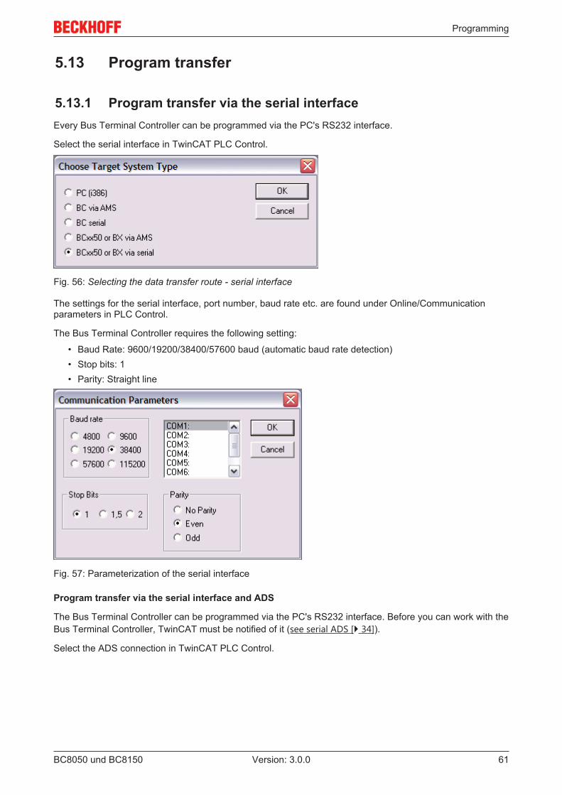
Programming
BC8050 und BC8150 61Version: 3.0.0
5.13 Program transfer
5.13.1 Program transfer via the serial interfaceEvery Bus Terminal Controller can be programmed via the PC's RS232 interface.
Select the serial interface in TwinCAT PLC Control.
Fig. 56: Selecting the data transfer route - serial interface
The settings for the serial interface, port number, baud rate etc. are found under Online/Communicationparameters in PLC Control.
The Bus Terminal Controller requires the following setting:
• Baud Rate: 9600/19200/38400/57600 baud (automatic baud rate detection)• Stop bits: 1• Parity: Straight line
Fig. 57: Parameterization of the serial interface
Program transfer via the serial interface and ADS
The Bus Terminal Controller can be programmed via the PC's RS232 interface. Before you can work with theBus Terminal Controller, TwinCAT must be notified of it (see serial ADS [} 34]).
Select the ADS connection in TwinCAT PLC Control.
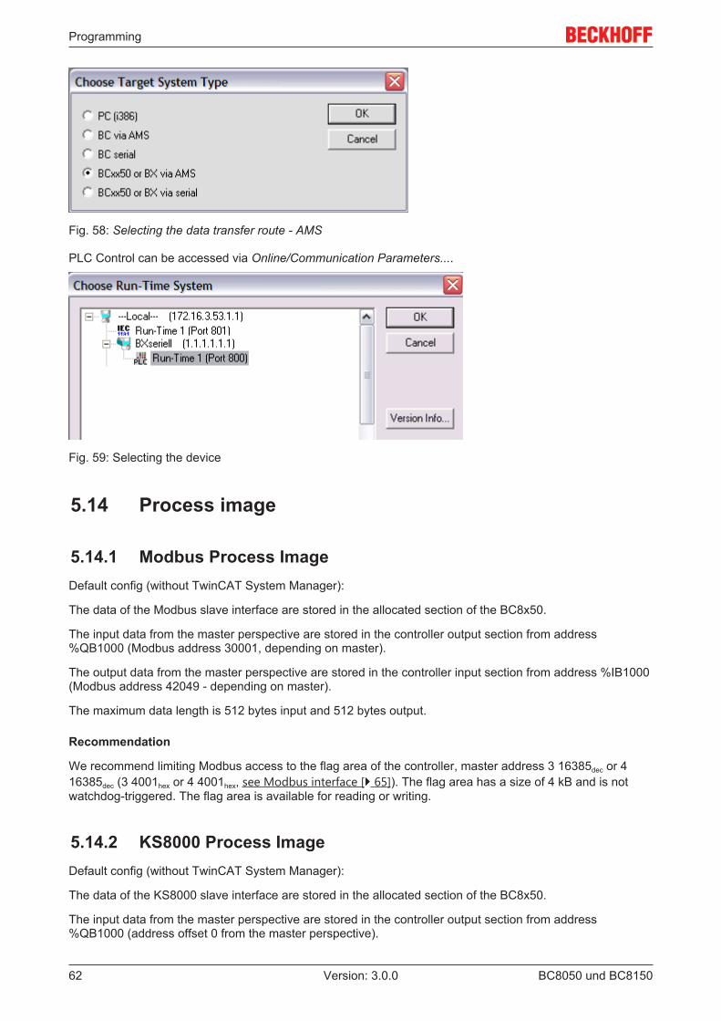
Programming
BC8050 und BC815062 Version: 3.0.0
Fig. 58: Selecting the data transfer route - AMS
PLC Control can be accessed via Online/Communication Parameters....
Fig. 59: Selecting the device
5.14 Process image
5.14.1 Modbus Process ImageDefault config (without TwinCAT System Manager):
The data of the Modbus slave interface are stored in the allocated section of the BC8x50.
The input data from the master perspective are stored in the controller output section from address%QB1000 (Modbus address 30001, depending on master).
The output data from the master perspective are stored in the controller input section from address %IB1000(Modbus address 42049 - depending on master).
The maximum data length is 512 bytes input and 512 bytes output.
Recommendation
We recommend limiting Modbus access to the flag area of the controller, master address 3 16385dec or 416385dec (3 4001hex or 4 4001hex, see Modbus interface [} 65]). The flag area has a size of 4 kB and is notwatchdog-triggered. The flag area is available for reading or writing.
5.14.2 KS8000 Process ImageDefault config (without TwinCAT System Manager):
The data of the KS8000 slave interface are stored in the allocated section of the BC8x50.
The input data from the master perspective are stored in the controller output section from address%QB1000 (address offset 0 from the master perspective).
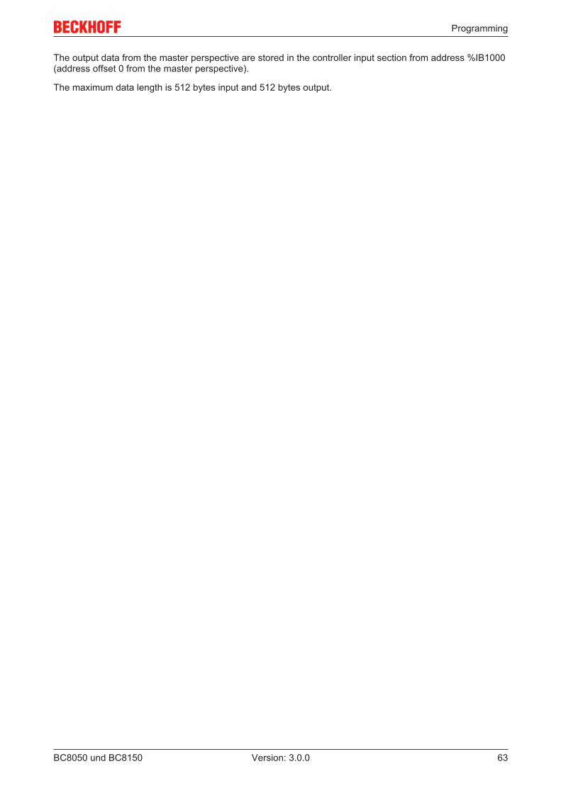
Programming
BC8050 und BC8150 63Version: 3.0.0
The output data from the master perspective are stored in the controller input section from address %IB1000(address offset 0 from the master perspective).
The maximum data length is 512 bytes input and 512 bytes output.
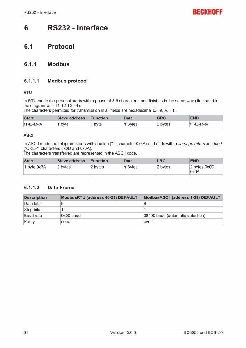
RS232 - Interface
BC8050 und BC815064 Version: 3.0.0
6 RS232 - Interface
6.1 Protocol
6.1.1 Modbus
6.1.1.1 Modbus protocol
RTU
In RTU mode the protocol starts with a pause of 3.5 characters, and finishes in the same way (illustrated inthe diagram with T1-T2-T3-T4).The characters permitted for transmission in all fields are hexadecimal 0... 9, A..., F.
Start Slave address Function Data CRC ENDt1-t2-t3-t4 1 byte 1 byte n Bytes 2 bytes t1-t2-t3-t4
ASCII
In ASCII mode the telegram starts with a colon (":", character 0x3A) and ends with a carriage return line feed("CRLF", characters 0x0D and 0x0A).The characters transferred are represented in the ASCII code.
Start Slave address Function Data LRC END1 byte 0x3A 2 bytes 2 bytes n Bytes 2 bytes 2 bytes 0x0D,
0x0A
6.1.1.2 Data Frame
Description ModbusRTU (address 40-59) DEFAULT ModbusASCII (address 1-39) DEFAULTData bits 8 8Stop bits 1 1Baud rate 9600 baud 38400 baud (automatic detection)Parity none even
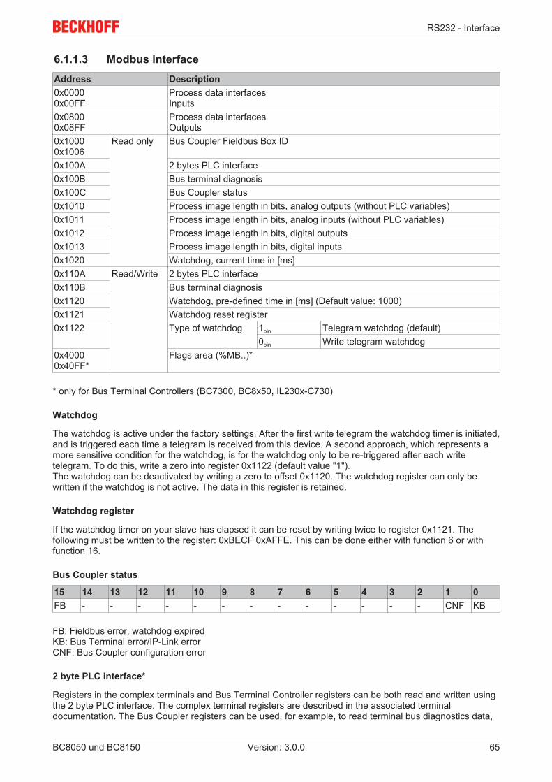
RS232 - Interface
BC8050 und BC8150 65Version: 3.0.0
6.1.1.3 Modbus interfaceAddress Description0x00000x00FF
Process data interfacesInputs
0x08000x08FF
Process data interfacesOutputs
0x10000x1006
Read only Bus Coupler Fieldbus Box ID
0x100A 2 bytes PLC interface0x100B Bus terminal diagnosis0x100C Bus Coupler status0x1010 Process image length in bits, analog outputs (without PLC variables)0x1011 Process image length in bits, analog inputs (without PLC variables)0x1012 Process image length in bits, digital outputs0x1013 Process image length in bits, digital inputs0x1020 Watchdog, current time in [ms]0x110A Read/Write 2 bytes PLC interface0x110B Bus terminal diagnosis0x1120 Watchdog, pre-defined time in [ms] (Default value: 1000)0x1121 Watchdog reset register0x1122 Type of watchdog 1bin Telegram watchdog (default)
0bin Write telegram watchdog0x40000x40FF*
Flags area (%MB..)*
* only for Bus Terminal Controllers (BC7300, BC8x50, IL230x-C730)
Watchdog
The watchdog is active under the factory settings. After the first write telegram the watchdog timer is initiated,and is triggered each time a telegram is received from this device. A second approach, which represents amore sensitive condition for the watchdog, is for the watchdog only to be re-triggered after each writetelegram. To do this, write a zero into register 0x1122 (default value "1").The watchdog can be deactivated by writing a zero to offset 0x1120. The watchdog register can only bewritten if the watchdog is not active. The data in this register is retained.
Watchdog register
If the watchdog timer on your slave has elapsed it can be reset by writing twice to register 0x1121. Thefollowing must be written to the register: 0xBECF 0xAFFE. This can be done either with function 6 or withfunction 16.
Bus Coupler status
15 14 13 12 11 10 9 8 7 6 5 4 3 2 1 0FB - - - - - - - - - - - - - CNF KB
FB: Fieldbus error, watchdog expiredKB: Bus Terminal error/IP-Link error CNF: Bus Coupler configuration error
2 byte PLC interface*
Registers in the complex terminals and Bus Terminal Controller registers can be both read and written usingthe 2 byte PLC interface. The complex terminal registers are described in the associated terminaldocumentation. The Bus Coupler registers can be used, for example, to read terminal bus diagnostics data,
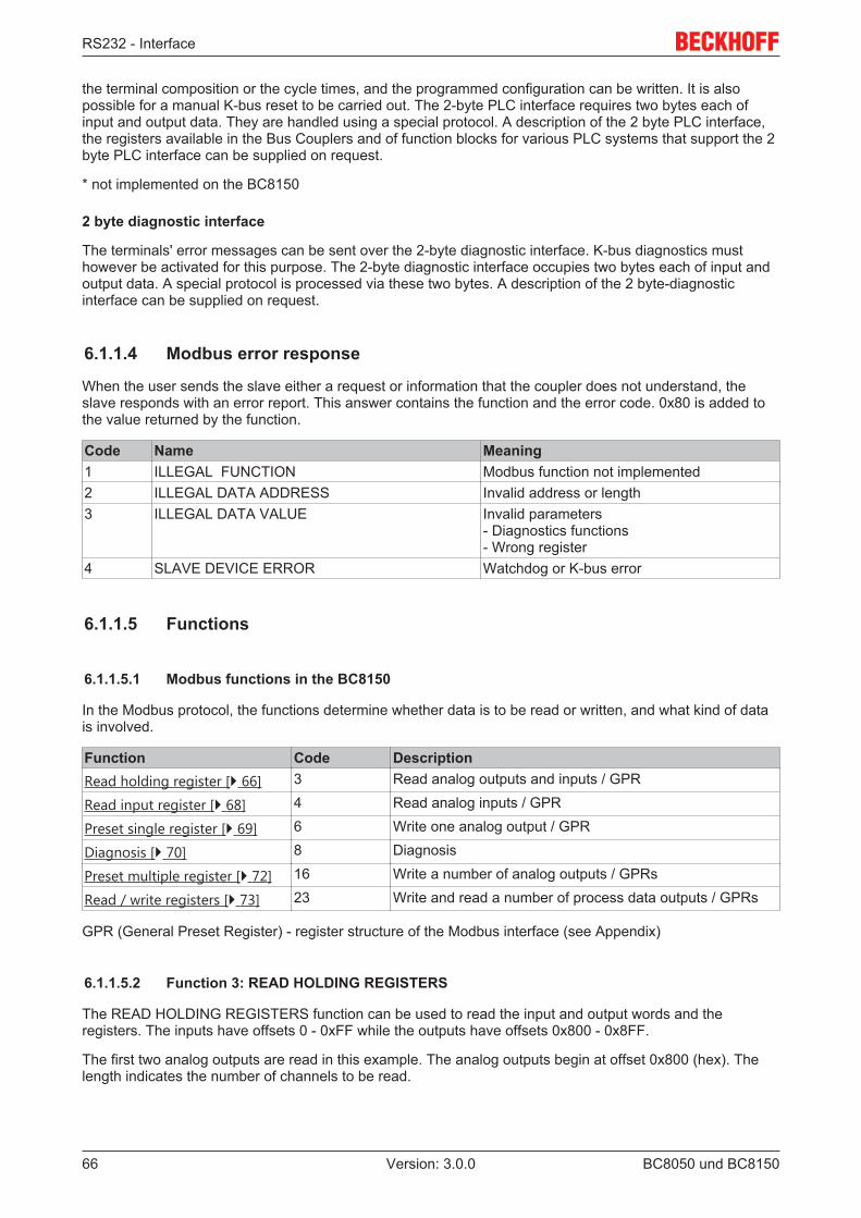
RS232 - Interface
BC8050 und BC815066 Version: 3.0.0
the terminal composition or the cycle times, and the programmed configuration can be written. It is alsopossible for a manual K-bus reset to be carried out. The 2-byte PLC interface requires two bytes each ofinput and output data. They are handled using a special protocol. A description of the 2 byte PLC interface,the registers available in the Bus Couplers and of function blocks for various PLC systems that support the 2byte PLC interface can be supplied on request.
* not implemented on the BC8150
2 byte diagnostic interface
The terminals' error messages can be sent over the 2-byte diagnostic interface. K-bus diagnostics musthowever be activated for this purpose. The 2-byte diagnostic interface occupies two bytes each of input andoutput data. A special protocol is processed via these two bytes. A description of the 2 byte-diagnosticinterface can be supplied on request.
6.1.1.4 Modbus error response
When the user sends the slave either a request or information that the coupler does not understand, theslave responds with an error report. This answer contains the function and the error code. 0x80 is added tothe value returned by the function.
Code Name Meaning1 ILLEGAL FUNCTION Modbus function not implemented2 ILLEGAL DATA ADDRESS Invalid address or length3 ILLEGAL DATA VALUE Invalid parameters
- Diagnostics functions- Wrong register
4 SLAVE DEVICE ERROR Watchdog or K-bus error
6.1.1.5 Functions
6.1.1.5.1 Modbus functions in the BC8150
In the Modbus protocol, the functions determine whether data is to be read or written, and what kind of datais involved.
Function Code DescriptionRead holding register [} 66] 3 Read analog outputs and inputs / GPR
Read input register [} 68] 4 Read analog inputs / GPR
Preset single register [} 69] 6 Write one analog output / GPR
Diagnosis [} 70] 8 Diagnosis
Preset multiple register [} 72] 16 Write a number of analog outputs / GPRs
Read / write registers [} 73] 23 Write and read a number of process data outputs / GPRs
GPR (General Preset Register) - register structure of the Modbus interface (see Appendix)
6.1.1.5.2 Function 3: READ HOLDING REGISTERS
The READ HOLDING REGISTERS function can be used to read the input and output words and theregisters. The inputs have offsets 0 - 0xFF while the outputs have offsets 0x800 - 0x8FF.
The first two analog outputs are read in this example. The analog outputs begin at offset 0x800 (hex). Thelength indicates the number of channels to be read.
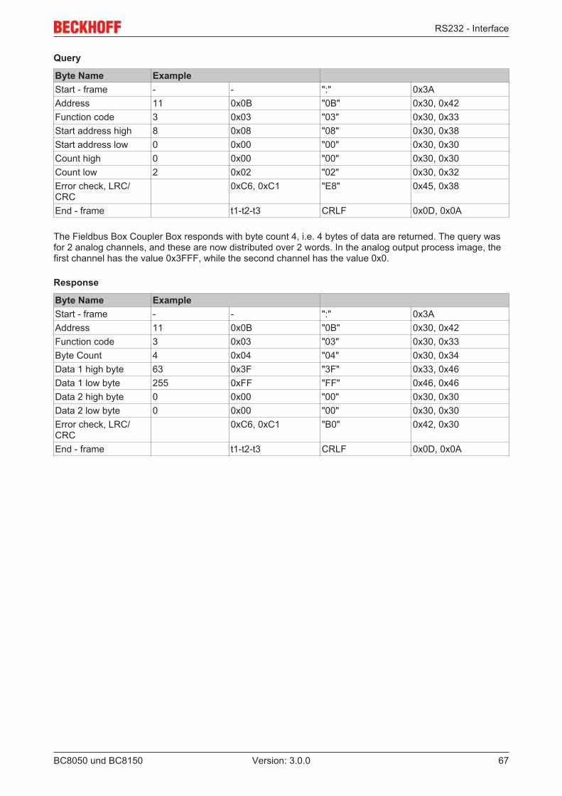
RS232 - Interface
BC8050 und BC8150 67Version: 3.0.0
Query
Byte Name ExampleStart - frame - - ":" 0x3AAddress 11 0x0B "0B" 0x30, 0x42Function code 3 0x03 "03" 0x30, 0x33Start address high 8 0x08 "08" 0x30, 0x38Start address low 0 0x00 "00" 0x30, 0x30Count high 0 0x00 "00" 0x30, 0x30Count low 2 0x02 "02" 0x30, 0x32Error check, LRC/CRC
0xC6, 0xC1 "E8" 0x45, 0x38
End - frame t1-t2-t3 CRLF 0x0D, 0x0A
The Fieldbus Box Coupler Box responds with byte count 4, i.e. 4 bytes of data are returned. The query wasfor 2 analog channels, and these are now distributed over 2 words. In the analog output process image, thefirst channel has the value 0x3FFF, while the second channel has the value 0x0.
Response
Byte Name ExampleStart - frame - - ":" 0x3AAddress 11 0x0B "0B" 0x30, 0x42Function code 3 0x03 "03" 0x30, 0x33Byte Count 4 0x04 "04" 0x30, 0x34Data 1 high byte 63 0x3F "3F" 0x33, 0x46Data 1 low byte 255 0xFF "FF" 0x46, 0x46Data 2 high byte 0 0x00 "00" 0x30, 0x30Data 2 low byte 0 0x00 "00" 0x30, 0x30Error check, LRC/CRC
0xC6, 0xC1 "B0" 0x42, 0x30
End - frame t1-t2-t3 CRLF 0x0D, 0x0A
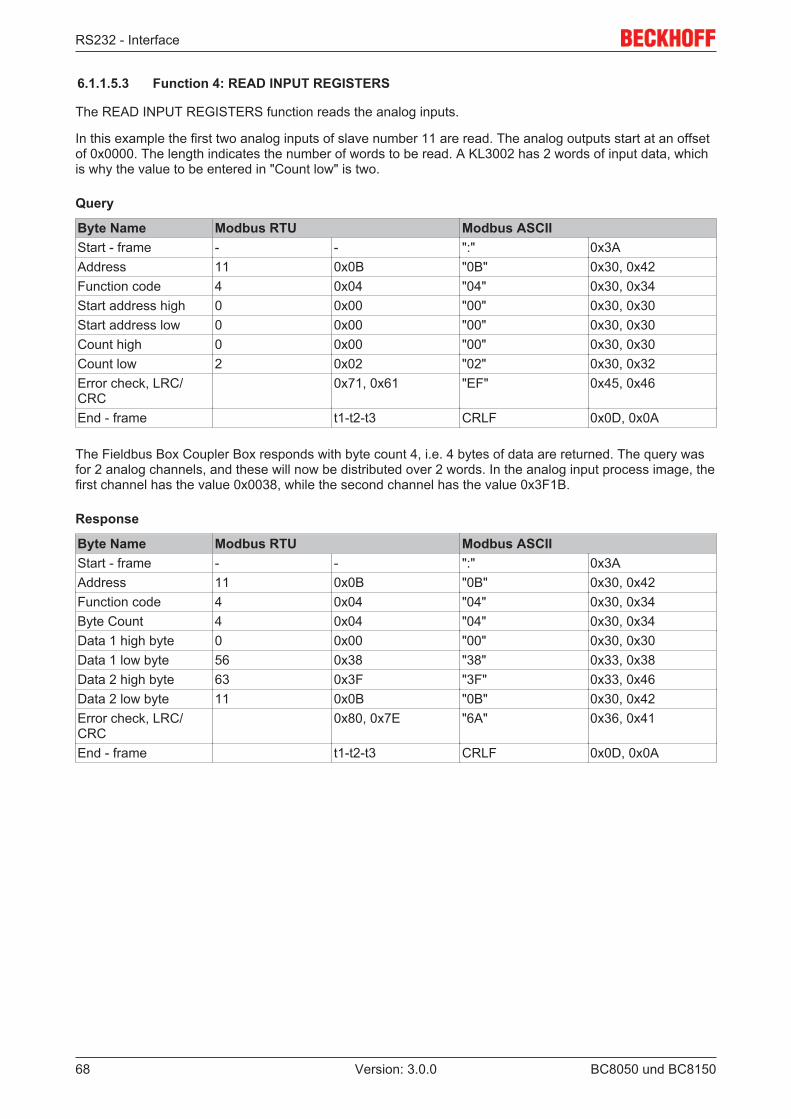
RS232 - Interface
BC8050 und BC815068 Version: 3.0.0
6.1.1.5.3 Function 4: READ INPUT REGISTERS
The READ INPUT REGISTERS function reads the analog inputs.
In this example the first two analog inputs of slave number 11 are read. The analog outputs start at an offsetof 0x0000. The length indicates the number of words to be read. A KL3002 has 2 words of input data, whichis why the value to be entered in "Count low" is two.
Query
Byte Name Modbus RTU Modbus ASCIIStart - frame - - ":" 0x3AAddress 11 0x0B "0B" 0x30, 0x42Function code 4 0x04 "04" 0x30, 0x34Start address high 0 0x00 "00" 0x30, 0x30Start address low 0 0x00 "00" 0x30, 0x30Count high 0 0x00 "00" 0x30, 0x30Count low 2 0x02 "02" 0x30, 0x32Error check, LRC/CRC
0x71, 0x61 "EF" 0x45, 0x46
End - frame t1-t2-t3 CRLF 0x0D, 0x0A
The Fieldbus Box Coupler Box responds with byte count 4, i.e. 4 bytes of data are returned. The query wasfor 2 analog channels, and these will now be distributed over 2 words. In the analog input process image, thefirst channel has the value 0x0038, while the second channel has the value 0x3F1B.
Response
Byte Name Modbus RTU Modbus ASCIIStart - frame - - ":" 0x3AAddress 11 0x0B "0B" 0x30, 0x42Function code 4 0x04 "04" 0x30, 0x34Byte Count 4 0x04 "04" 0x30, 0x34Data 1 high byte 0 0x00 "00" 0x30, 0x30Data 1 low byte 56 0x38 "38" 0x33, 0x38Data 2 high byte 63 0x3F "3F" 0x33, 0x46Data 2 low byte 11 0x0B "0B" 0x30, 0x42Error check, LRC/CRC
0x80, 0x7E "6A" 0x36, 0x41
End - frame t1-t2-t3 CRLF 0x0D, 0x0A
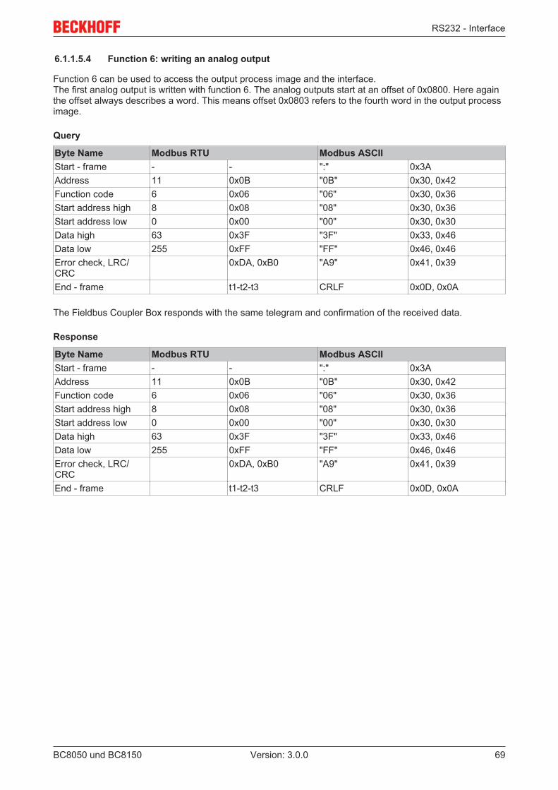
RS232 - Interface
BC8050 und BC8150 69Version: 3.0.0
6.1.1.5.4 Function 6: writing an analog output
Function 6 can be used to access the output process image and the interface.The first analog output is written with function 6. The analog outputs start at an offset of 0x0800. Here againthe offset always describes a word. This means offset 0x0803 refers to the fourth word in the output processimage.
Query
Byte Name Modbus RTU Modbus ASCIIStart - frame - - ":" 0x3AAddress 11 0x0B "0B" 0x30, 0x42Function code 6 0x06 "06" 0x30, 0x36Start address high 8 0x08 "08" 0x30, 0x36Start address low 0 0x00 "00" 0x30, 0x30Data high 63 0x3F "3F" 0x33, 0x46Data low 255 0xFF "FF" 0x46, 0x46Error check, LRC/CRC
0xDA, 0xB0 "A9" 0x41, 0x39
End - frame t1-t2-t3 CRLF 0x0D, 0x0A
The Fieldbus Coupler Box responds with the same telegram and confirmation of the received data.
Response
Byte Name Modbus RTU Modbus ASCIIStart - frame - - ":" 0x3AAddress 11 0x0B "0B" 0x30, 0x42Function code 6 0x06 "06" 0x30, 0x36Start address high 8 0x08 "08" 0x30, 0x36Start address low 0 0x00 "00" 0x30, 0x30Data high 63 0x3F "3F" 0x33, 0x46Data low 255 0xFF "FF" 0x46, 0x46Error check, LRC/CRC
0xDA, 0xB0 "A9" 0x41, 0x39
End - frame t1-t2-t3 CRLF 0x0D, 0x0A
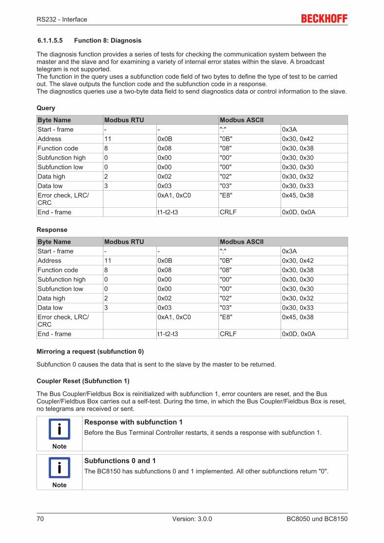
RS232 - Interface
BC8050 und BC815070 Version: 3.0.0
6.1.1.5.5 Function 8: Diagnosis
The diagnosis function provides a series of tests for checking the communication system between themaster and the slave and for examining a variety of internal error states within the slave. A broadcasttelegram is not supported.The function in the query uses a subfunction code field of two bytes to define the type of test to be carriedout. The slave outputs the function code and the subfunction code in a response. The diagnostics queries use a two-byte data field to send diagnostics data or control information to the slave.
Query
Byte Name Modbus RTU Modbus ASCIIStart - frame - - ":" 0x3AAddress 11 0x0B "0B" 0x30, 0x42Function code 8 0x08 "08" 0x30, 0x38Subfunction high 0 0x00 "00" 0x30, 0x30Subfunction low 0 0x00 "00" 0x30, 0x30Data high 2 0x02 "02" 0x30, 0x32Data low 3 0x03 "03" 0x30, 0x33Error check, LRC/CRC
0xA1, 0xC0 "E8" 0x45, 0x38
End - frame t1-t2-t3 CRLF 0x0D, 0x0A
Response
Byte Name Modbus RTU Modbus ASCIIStart - frame - - ":" 0x3AAddress 11 0x0B "0B" 0x30, 0x42Function code 8 0x08 "08" 0x30, 0x38Subfunction high 0 0x00 "00" 0x30, 0x30Subfunction low 0 0x00 "00" 0x30, 0x30Data high 2 0x02 "02" 0x30, 0x32Data low 3 0x03 "03" 0x30, 0x33Error check, LRC/CRC
0xA1, 0xC0 "E8" 0x45, 0x38
End - frame t1-t2-t3 CRLF 0x0D, 0x0A
Mirroring a request (subfunction 0)
Subfunction 0 causes the data that is sent to the slave by the master to be returned.
Coupler Reset (Subfunction 1)
The Bus Coupler/Fieldbus Box is reinitialized with subfunction 1, error counters are reset, and the BusCoupler/Fieldbus Box carries out a self-test. During the time, in which the Bus Coupler/Fieldbus Box is reset,no telegrams are received or sent.
Note
Response with subfunction 1Before the Bus Terminal Controller restarts, it sends a response with subfunction 1.
Note
Subfunctions 0 and 1The BC8150 has subfunctions 0 and 1 implemented. All other subfunctions return "0".
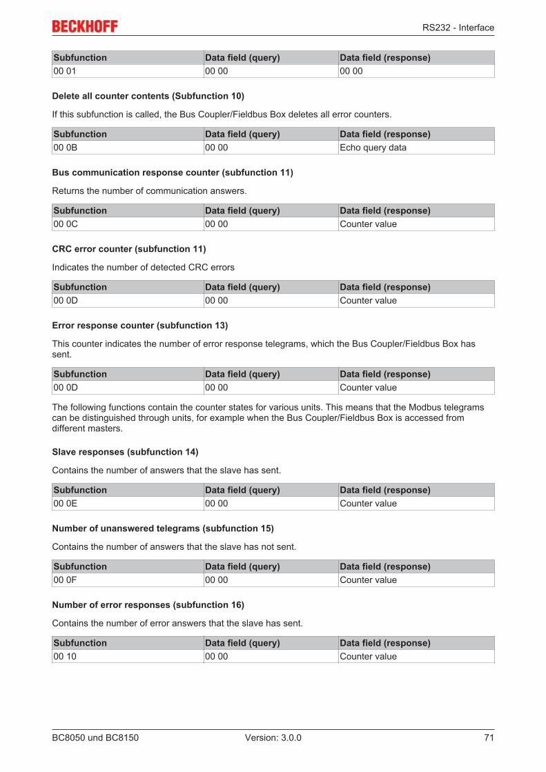
RS232 - Interface
BC8050 und BC8150 71Version: 3.0.0
Subfunction Data field (query) Data field (response)00 01 00 00 00 00
Delete all counter contents (Subfunction 10)
If this subfunction is called, the Bus Coupler/Fieldbus Box deletes all error counters.
Subfunction Data field (query) Data field (response)00 0B 00 00 Echo query data
Bus communication response counter (subfunction 11)
Returns the number of communication answers.
Subfunction Data field (query) Data field (response)00 0C 00 00 Counter value
CRC error counter (subfunction 11)
Indicates the number of detected CRC errors
Subfunction Data field (query) Data field (response)00 0D 00 00 Counter value
Error response counter (subfunction 13)
This counter indicates the number of error response telegrams, which the Bus Coupler/Fieldbus Box hassent.
Subfunction Data field (query) Data field (response)00 0D 00 00 Counter value
The following functions contain the counter states for various units. This means that the Modbus telegramscan be distinguished through units, for example when the Bus Coupler/Fieldbus Box is accessed fromdifferent masters.
Slave responses (subfunction 14)
Contains the number of answers that the slave has sent.
Subfunction Data field (query) Data field (response)00 0E 00 00 Counter value
Number of unanswered telegrams (subfunction 15)
Contains the number of answers that the slave has not sent.
Subfunction Data field (query) Data field (response)00 0F 00 00 Counter value
Number of error responses (subfunction 16)
Contains the number of error answers that the slave has sent.
Subfunction Data field (query) Data field (response)00 10 00 00 Counter value
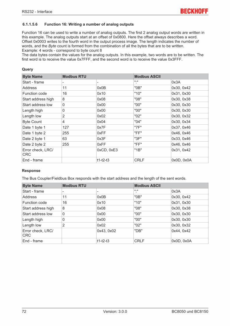
RS232 - Interface
BC8050 und BC815072 Version: 3.0.0
6.1.1.5.6 Function 16: Writing a number of analog outputs
Function 16 can be used to write a number of analog outputs. The first 2 analog output words are written inthis example. The analog outputs start at an offset of 0x0800. Here the offset always describes a word.Offset 0x0003 writes to the fourth word in the output process image. The length indicates the number ofwords, and the Byte count is formed from the combination of all the bytes that are to be written.Example: 4 words - correspond to byte count 8The data bytes contain the values for the analog outputs. In this example, two words are to be written. Thefirst word is to receive the value 0x7FFF, and the second word is to receive the value 0x3FFF.
Query
Byte Name Modbus RTU Modbus ASCIIStart - frame - - ":" 0x3AAddress 11 0x0B "0B" 0x30, 0x42Function code 16 0x10 "10" 0x31, 0x30Start address high 8 0x08 "08" 0x30, 0x38Start address low 0 0x00 "00" 0x30, 0x30Length high 0 0x00 "00" 0x30, 0x30Length low 2 0x02 "02" 0x30, 0x32Byte Count 4 0x04 "04" 0x30, 0x34Date 1 byte 1 127 0x7F "7F" 0x37, 0x46Date 1 byte 2 255 0xFF "FF" 0x46, 0x46Date 2 byte 1 63 0x3F "3F" 0x33, 0x46Date 2 byte 2 255 0xFF "FF" 0x46, 0x46Error check, LRC/CRC
0xCD, 0xE3 "1B" 0x31, 0x42
End - frame t1-t2-t3 CRLF 0x0D, 0x0A
Response
The Bus Coupler/Fieldbus Box responds with the start address and the length of the sent words.
Byte Name Modbus RTU Modbus ASCIIStart - frame - - ":" 0x3AAddress 11 0x0B "0B" 0x30, 0x42Function code 16 0x10 "10" 0x31, 0x30Start address high 8 0x08 "08" 0x30, 0x38Start address low 0 0x00 "00" 0x30, 0x30Length high 0 0x00 "00" 0x30, 0x30Length low 2 0x02 "02" 0x30, 0x32Error check, LRC/CRC
0x43, 0x02 "DB" 0x44, 0x42
End - frame t1-t2-t3 CRLF 0x0D, 0x0A
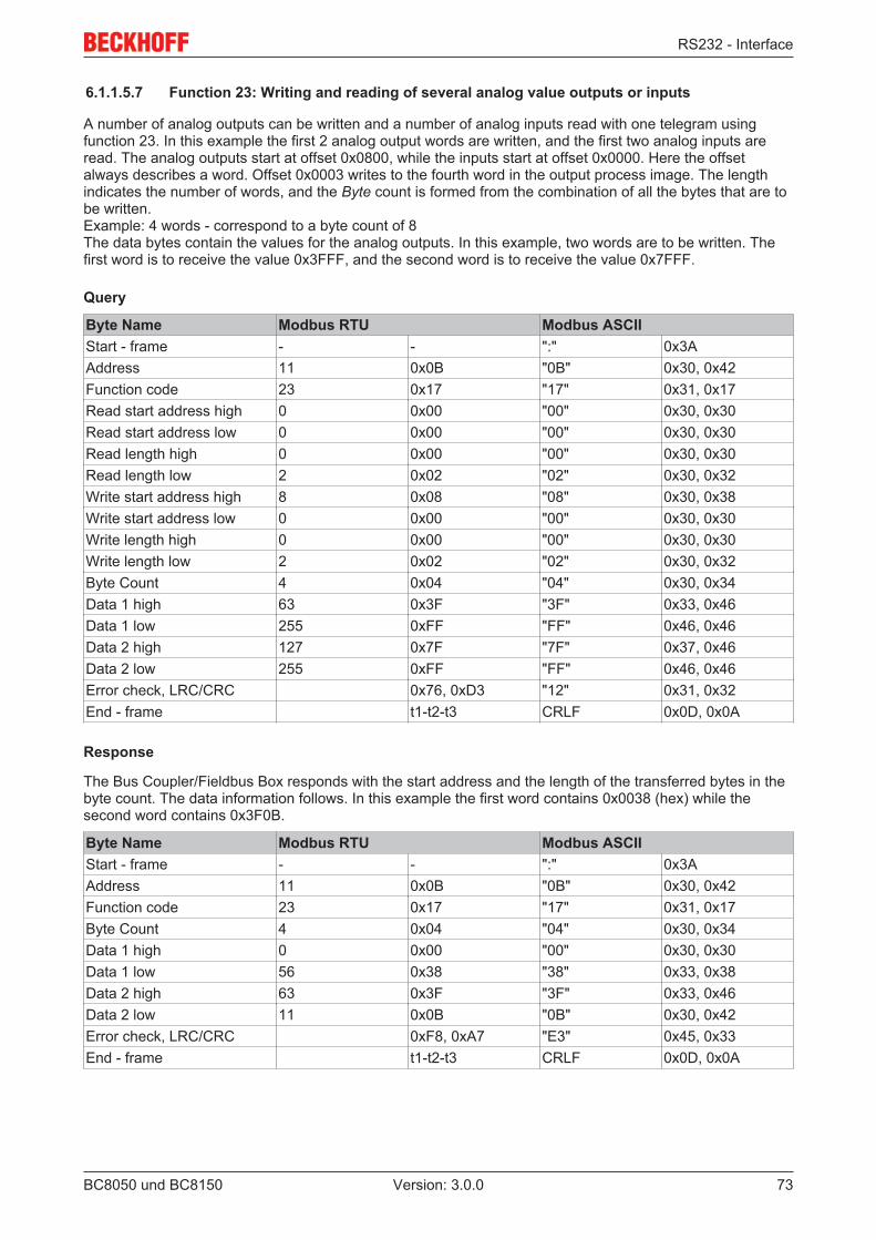
RS232 - Interface
BC8050 und BC8150 73Version: 3.0.0
6.1.1.5.7 Function 23: Writing and reading of several analog value outputs or inputs
A number of analog outputs can be written and a number of analog inputs read with one telegram usingfunction 23. In this example the first 2 analog output words are written, and the first two analog inputs areread. The analog outputs start at offset 0x0800, while the inputs start at offset 0x0000. Here the offsetalways describes a word. Offset 0x0003 writes to the fourth word in the output process image. The lengthindicates the number of words, and the Byte count is formed from the combination of all the bytes that are tobe written.Example: 4 words - correspond to a byte count of 8The data bytes contain the values for the analog outputs. In this example, two words are to be written. Thefirst word is to receive the value 0x3FFF, and the second word is to receive the value 0x7FFF.
Query
Byte Name Modbus RTU Modbus ASCIIStart - frame - - ":" 0x3AAddress 11 0x0B "0B" 0x30, 0x42Function code 23 0x17 "17" 0x31, 0x17Read start address high 0 0x00 "00" 0x30, 0x30Read start address low 0 0x00 "00" 0x30, 0x30Read length high 0 0x00 "00" 0x30, 0x30Read length low 2 0x02 "02" 0x30, 0x32Write start address high 8 0x08 "08" 0x30, 0x38Write start address low 0 0x00 "00" 0x30, 0x30Write length high 0 0x00 "00" 0x30, 0x30Write length low 2 0x02 "02" 0x30, 0x32Byte Count 4 0x04 "04" 0x30, 0x34Data 1 high 63 0x3F "3F" 0x33, 0x46Data 1 low 255 0xFF "FF" 0x46, 0x46Data 2 high 127 0x7F "7F" 0x37, 0x46Data 2 low 255 0xFF "FF" 0x46, 0x46Error check, LRC/CRC 0x76, 0xD3 "12" 0x31, 0x32End - frame t1-t2-t3 CRLF 0x0D, 0x0A
Response
The Bus Coupler/Fieldbus Box responds with the start address and the length of the transferred bytes in thebyte count. The data information follows. In this example the first word contains 0x0038 (hex) while thesecond word contains 0x3F0B.
Byte Name Modbus RTU Modbus ASCIIStart - frame - - ":" 0x3AAddress 11 0x0B "0B" 0x30, 0x42Function code 23 0x17 "17" 0x31, 0x17Byte Count 4 0x04 "04" 0x30, 0x34Data 1 high 0 0x00 "00" 0x30, 0x30Data 1 low 56 0x38 "38" 0x33, 0x38Data 2 high 63 0x3F "3F" 0x33, 0x46Data 2 low 11 0x0B "0B" 0x30, 0x42Error check, LRC/CRC 0xF8, 0xA7 "E3" 0x45, 0x33End - frame t1-t2-t3 CRLF 0x0D, 0x0A
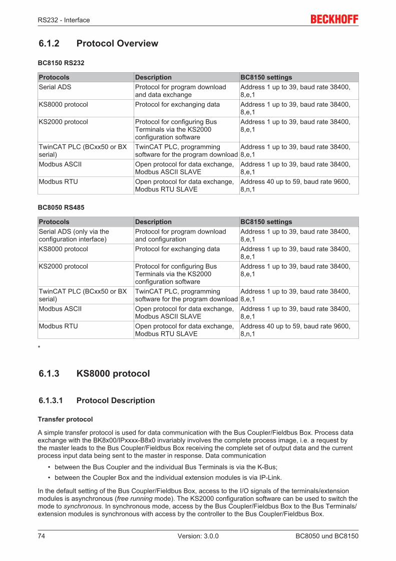
RS232 - Interface
BC8050 und BC815074 Version: 3.0.0
6.1.2 Protocol Overview
BC8150 RS232
Protocols Description BC8150 settingsSerial ADS Protocol for program download
and data exchangeAddress 1 up to 39, baud rate 38400,8,e,1
KS8000 protocol Protocol for exchanging data Address 1 up to 39, baud rate 38400,8,e,1
KS2000 protocol Protocol for configuring BusTerminals via the KS2000configuration software
Address 1 up to 39, baud rate 38400,8,e,1
TwinCAT PLC (BCxx50 or BXserial)
TwinCAT PLC, programmingsoftware for the program download
Address 1 up to 39, baud rate 38400,8,e,1
Modbus ASCII Open protocol for data exchange,Modbus ASCII SLAVE
Address 1 up to 39, baud rate 38400,8,e,1
Modbus RTU Open protocol for data exchange,Modbus RTU SLAVE
Address 40 up to 59, baud rate 9600,8,n,1
BC8050 RS485
Protocols Description BC8150 settingsSerial ADS (only via theconfiguration interface)
Protocol for program downloadand configuration
Address 1 up to 39, baud rate 38400,8,e,1
KS8000 protocol Protocol for exchanging data Address 1 up to 39, baud rate 38400,8,e,1
KS2000 protocol Protocol for configuring BusTerminals via the KS2000configuration software
Address 1 up to 39, baud rate 38400,8,e,1
TwinCAT PLC (BCxx50 or BXserial)
TwinCAT PLC, programmingsoftware for the program download
Address 1 up to 39, baud rate 38400,8,e,1
Modbus ASCII Open protocol for data exchange,Modbus ASCII SLAVE
Address 1 up to 39, baud rate 38400,8,e,1
Modbus RTU Open protocol for data exchange,Modbus RTU SLAVE
Address 40 up to 59, baud rate 9600,8,n,1
*
6.1.3 KS8000 protocol
6.1.3.1 Protocol Description
Transfer protocol
A simple transfer protocol is used for data communication with the Bus Coupler/Fieldbus Box. Process dataexchange with the BK8x00/IPxxxx-B8x0 invariably involves the complete process image, i.e. a request bythe master leads to the Bus Coupler/Fieldbus Box receiving the complete set of output data and the currentprocess input data being sent to the master in response. Data communication
• between the Bus Coupler and the individual Bus Terminals is via the K-Bus;• between the Coupler Box and the individual extension modules is via IP-Link.
In the default setting of the Bus Coupler/Fieldbus Box, access to the I/O signals of the terminals/extensionmodules is asynchronous (free running mode). The KS2000 configuration software can be used to switch themode to synchronous. In synchronous mode, access by the Bus Coupler/Fieldbus Box to the Bus Terminals/extension modules is synchronous with access by the controller to the Bus Coupler/Fieldbus Box.
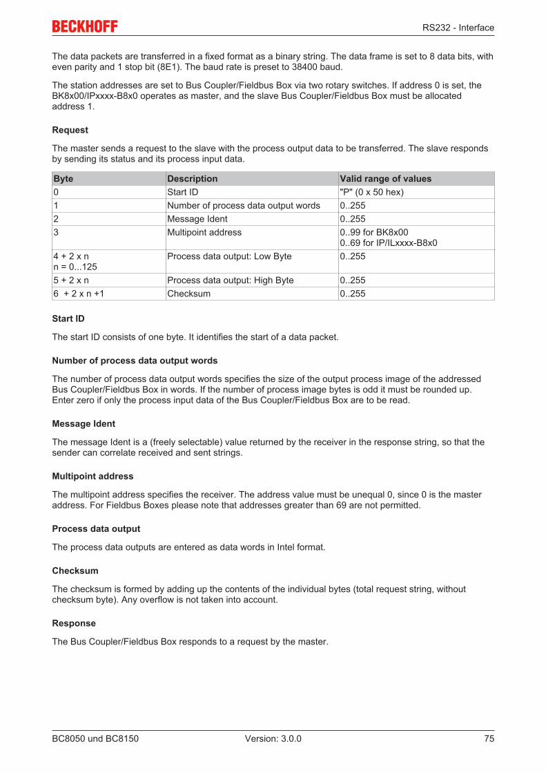
RS232 - Interface
BC8050 und BC8150 75Version: 3.0.0
The data packets are transferred in a fixed format as a binary string. The data frame is set to 8 data bits, witheven parity and 1 stop bit (8E1). The baud rate is preset to 38400 baud.
The station addresses are set to Bus Coupler/Fieldbus Box via two rotary switches. If address 0 is set, theBK8x00/IPxxxx-B8x0 operates as master, and the slave Bus Coupler/Fieldbus Box must be allocatedaddress 1.
Request
The master sends a request to the slave with the process output data to be transferred. The slave respondsby sending its status and its process input data.
Byte Description Valid range of values0 Start ID "P" (0 x 50 hex)1 Number of process data output words 0..2552 Message Ident 0..2553 Multipoint address 0..99 for BK8x00
0..69 for IP/ILxxxx-B8x04 + 2 x nn = 0...125
Process data output: Low Byte 0..255
5 + 2 x n Process data output: High Byte 0..2556 + 2 x n +1 Checksum 0..255
Start ID
The start ID consists of one byte. It identifies the start of a data packet.
Number of process data output words
The number of process data output words specifies the size of the output process image of the addressedBus Coupler/Fieldbus Box in words. If the number of process image bytes is odd it must be rounded up.Enter zero if only the process input data of the Bus Coupler/Fieldbus Box are to be read.
Message Ident
The message Ident is a (freely selectable) value returned by the receiver in the response string, so that thesender can correlate received and sent strings.
Multipoint address
The multipoint address specifies the receiver. The address value must be unequal 0, since 0 is the masteraddress. For Fieldbus Boxes please note that addresses greater than 69 are not permitted.
Process data output
The process data outputs are entered as data words in Intel format.
Checksum
The checksum is formed by adding up the contents of the individual bytes (total request string, withoutchecksum byte). Any overflow is not taken into account.
Response
The Bus Coupler/Fieldbus Box responds to a request by the master.
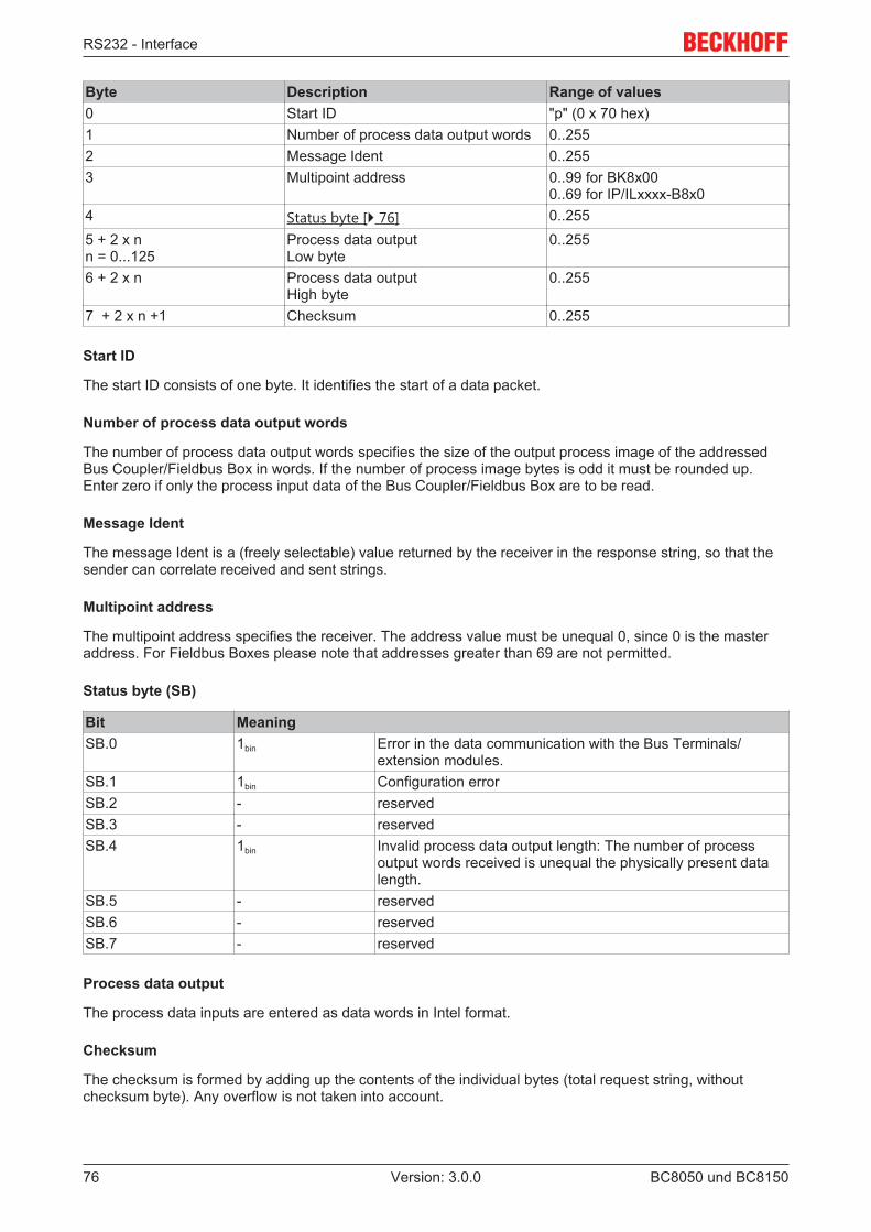
RS232 - Interface
BC8050 und BC815076 Version: 3.0.0
Byte Description Range of values0 Start ID "p" (0 x 70 hex)1 Number of process data output words 0..2552 Message Ident 0..2553 Multipoint address 0..99 for BK8x00
0..69 for IP/ILxxxx-B8x04 Status byte [} 76] 0..2555 + 2 x nn = 0...125
Process data outputLow byte
0..255
6 + 2 x n Process data outputHigh byte
0..255
7 + 2 x n +1 Checksum 0..255
Start ID
The start ID consists of one byte. It identifies the start of a data packet.
Number of process data output words
The number of process data output words specifies the size of the output process image of the addressedBus Coupler/Fieldbus Box in words. If the number of process image bytes is odd it must be rounded up.Enter zero if only the process input data of the Bus Coupler/Fieldbus Box are to be read.
Message Ident
The message Ident is a (freely selectable) value returned by the receiver in the response string, so that thesender can correlate received and sent strings.
Multipoint address
The multipoint address specifies the receiver. The address value must be unequal 0, since 0 is the masteraddress. For Fieldbus Boxes please note that addresses greater than 69 are not permitted.
Status byte (SB)
Bit MeaningSB.0 1bin Error in the data communication with the Bus Terminals/
extension modules.SB.1 1bin Configuration errorSB.2 - reservedSB.3 - reservedSB.4 1bin Invalid process data output length: The number of process
output words received is unequal the physically present datalength.
SB.5 - reservedSB.6 - reservedSB.7 - reserved
Process data output
The process data inputs are entered as data words in Intel format.
Checksum
The checksum is formed by adding up the contents of the individual bytes (total request string, withoutchecksum byte). Any overflow is not taken into account.
RS232 - Interface
BC8050 und BC8150 77Version: 3.0.0
6.1.3.2 KS8000 Communication Software
Fig. 60: Communication library icon
The Beckhoff KS8000 Communication Library provides functions with which it is possible to communicatewith the serial Bus Couplers (BK8000, BK8100, IP/ILxxxx-B8x0) easily via a serial PC interface. The KS8000can be used as an OCX with all programming languages that use the Component Object Model (COM)specifications from Microsoft (VC++, Visual Basic from version 4.0, Delphi, Java, etc). The KS8000 libraryalso has a DLL interface for any other C/C++ programs.
Accessing the process image
Via the serial PC interface the KS8000 enables access to the input and output process image of the BK8x00Bus Couplers or the IP/ILxxxx-B8x0 Fieldbus Boxes.
With each serial PC interface, communication with- a BK8100 coupler (RS232) or- a Fieldbus Box IP/ILxxxx-B810 (RS232) or- up to 99 BK8000 couplers (RS485) or- up to 69 Fieldbus Boxes IP/ILxxxx-B800 (RS485)can be established. Such communication transfers the whole of the input and output process image. Thecommunication duration therefore depends on the size of the process image. For example, with an RS232coupler at 38400 baud and
• a process image of one word, the communication duration is approx. 6 ms;• a process image of 15 words, the communication duration is approx. 20 ms.
Interface for LabVIEW applications
The KS8000 contains an interface for the LabVIEW programming software from National Instruments.LabVIEW solutions consist of what are known as front panels, which serve as the man/machine interface,and of a block diagram, which embodies the actual control program. KS8000 provides LabVIEW users with agreatly simplified method of access to all the process data.
Operation of KS8000 or TwinCAT via the RS485COM port requires a PC card that automatically switchesbetween send and receive mode without echo (e.g. C9900-A440: RS 485 high speed with 2 serial interfaces,optically decoupled, overvoltage protection, ISA bus).
6.2 Introduction to the system
6.2.1 Overview of the physical structure of RS232The serial, asynchronous RS232C or V.24 communication interface is a widely used as a simple physicalconnection for exchanging data between two systems. The RS232 interface only describes the physicalstructure and not the protocol or the application layer.
The data are applied sequentially for the duration of one bit. Synchronization is based on start and stop bits.Asynchronous data transfer requires no clock line. This means that a minimum of 3 lines are required, i.e.one for sending, one for receiving, and one for GND. Since in each case one line is available for sending andone for receiving, the technique is referred to as full duplex transfer. All devices can send or receive asrequired, since they have a dedicated line available.
The RS232C or V.24 interface operates bipolar with +12 V / -12 V voltage level (+3 V...+12 V = "0" and-3 V...-12 V = "1" ). The same baud rate, number of data bits, number of stop bits, and data verification of theso-called parity bit have to be used on both sides. This is usually described as 9600, 8, e, 1 (i.e. 9600 baud,8 data bits, even parity verification, one stop bit).
RS232 - Interface
BC8050 und BC815078 Version: 3.0.0
6.2.2 Topology of the physical RS232 structureRS232 is a peer-to-peer connection. The means that only two devices can be connected at any time. Themaximum cable length is 15 meters.
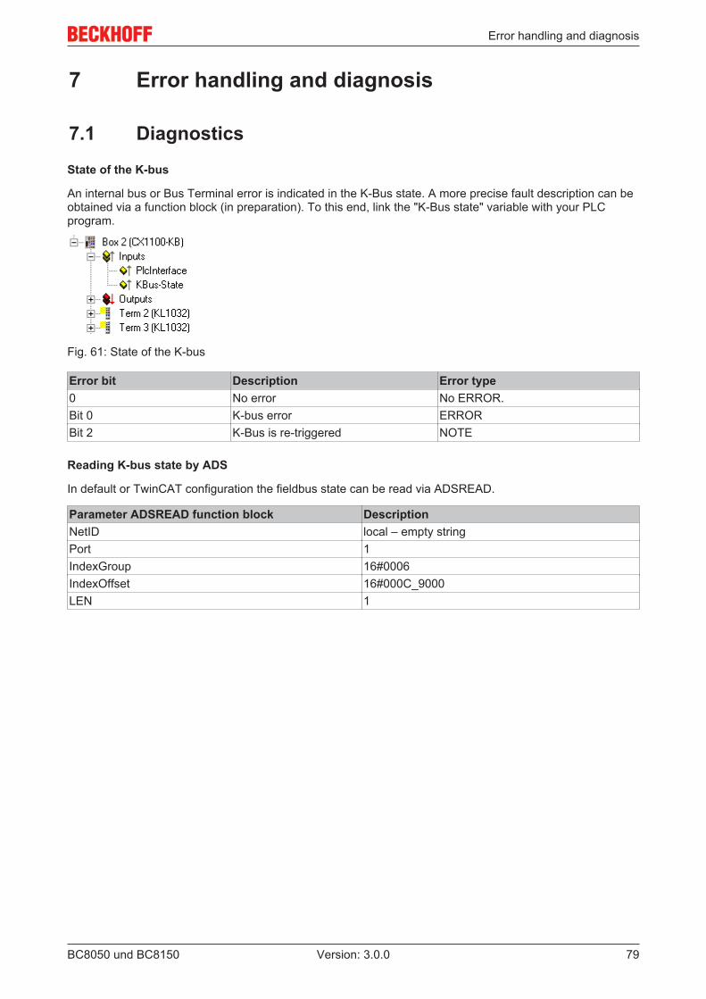
Error handling and diagnosis
BC8050 und BC8150 79Version: 3.0.0
7 Error handling and diagnosis
7.1 Diagnostics
State of the K-bus
An internal bus or Bus Terminal error is indicated in the K-Bus state. A more precise fault description can beobtained via a function block (in preparation). To this end, link the "K-Bus state" variable with your PLCprogram.
Fig. 61: State of the K-bus
Error bit Description Error type0 No error No ERROR.Bit 0 K-bus error ERRORBit 2 K-Bus is re-triggered NOTE
Reading K-bus state by ADS
In default or TwinCAT configuration the fieldbus state can be read via ADSREAD.
Parameter ADSREAD function block DescriptionNetID local – empty stringPort 1IndexGroup 16#0006IndexOffset 16#000C_9000LEN 1
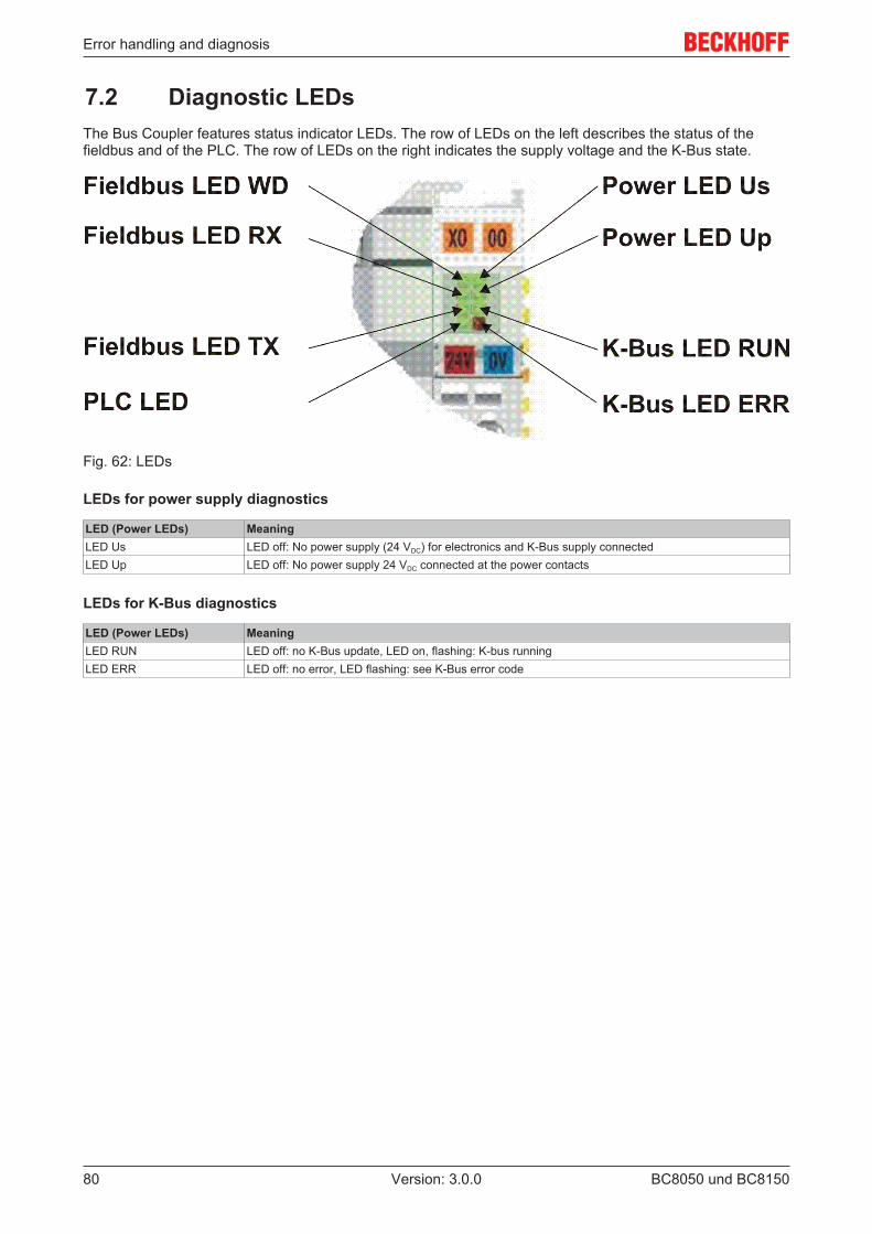
Error handling and diagnosis
BC8050 und BC815080 Version: 3.0.0
7.2 Diagnostic LEDsThe Bus Coupler features status indicator LEDs. The row of LEDs on the left describes the status of thefieldbus and of the PLC. The row of LEDs on the right indicates the supply voltage and the K-Bus state.
Fig. 62: LEDs
LEDs for power supply diagnostics
LED (Power LEDs) MeaningLED Us LED off: No power supply (24 VDC) for electronics and K-Bus supply connectedLED Up LED off: No power supply 24 VDC connected at the power contacts
LEDs for K-Bus diagnostics
LED (Power LEDs) MeaningLED RUN LED off: no K-Bus update, LED on, flashing: K-bus runningLED ERR LED off: no error, LED flashing: see K-Bus error code
Error handling and diagnosis
BC8050 und BC8150 81Version: 3.0.0
K-Bus error code diagnosis
Error code
Error argument
Description Remedy
0 - EMC problems • Check power supply for undervoltage or overvoltage peaks
• Implement EMC measures
• If a K-bus error is present, it can be localized by a restart of thecoupler (by switching it off and then on again)
1 0 EEPROM checksum error Enter factory settings with the KS2000 configuration software1 Code buffer overflow Insert fewer Bus Terminals. Too many entries in the table for the pro-
grammed configuration2 Unknown data type Software update required for the Bus Coupler
2 - Reserve -3 0 K-bus command error • No Bus Terminal inserted
• One of the Bus Terminals is defective; halve the number of BusTerminals attached and check whether the error is still presentwith the remaining Bus Terminals. Repeat until the defectiveBus Terminal is located.
4 0 K-bus data error, break be-hind the Bus Coupler
Check whether the n+1 Bus Terminal is correctly connected; replace ifnecessary.
n Break behind Bus Terminal n Check whether the KL9010 Bus End Terminal is connected5 n K-bus error in register com-
munication with Bus Terminaln
Exchange the nth Bus Terminal
6 0 Error at initialization Exchange Bus Coupler1 Internal data error Perform a hardware reset on the Bus Coupler (switch off and on again)2 DIP switch changed after a
software resetPerform a hardware reset on the Bus Coupler (switch off and on again)
7 0 Note: cycle time was ex-ceeded
Warning: the set cycle time was exceeded. This indication (flashingLEDs) can only be cleared by booting the Bus Coupler again.Remedy: increase the cycle time
9 0 Checksum error in Flash pro-gram
Re-transfer the program to the Bus Terminal Controller
1 Incorrect or faulty library im-plemented
Remove the faulty library
10 n Bus Terminal n is not consis-tent with the configuration thatexisted when the boot projectwas created
Check the nth Bus Terminal. The boot project must be deleted if the in-sertion of an nth Bus Terminal is intentional.
14 n nth Bus Terminal has thewrong format
Start the Bus Coupler again, and if the error occurs again then ex-change the Bus Terminal
15 n Number of Bus Terminals isno longer correct
Start the Bus Coupler again. If the error occurs again, restore the man-ufacturers setting using the KS2000 configuration software
16 n Length of the K-bus data is nolonger correct
Start the Bus Coupler again. If the error occurs again, restore the man-ufacturers setting using the KS2000 configuration software
LED bus - fieldbus diagnostics
LED MeaningLED WD not implementedLED RX Flashes when data are being receivedLED TX Flashes when data are being sent
LED PLC - PLC diagnostics
LED MeaningPLC LED LED on: PLC running,
LED off: PLC stopped
Appendix
BC8050 und BC815082 Version: 3.0.0
8 Appendix
8.1 First steps with the BC8150
in preparation
8.2 Switching between controllers
Switching from BCxx00 to BCxx50/BCxx20
File names
In the Bus Terminal controllers of the BCxx50 and BCxx20 series, libraries have the extension *.lbx,programs have the extension *.prx.
Flag variables
The allocated flag variables
• of the BCxx00 are assigned %MB0...%MB511 (except BC9000/BC9100: %MB0...%B4095).• of the BCxx20 are assigned %MB0...%MB4095• of the BCxx50 are assigned %MB0...%MB4095
Status information such as K-bus/fieldbus status and cycle tick is not copied to the BCxx50/BCxx20. Thisinformation is available in TcSystemBCxx50.lbx as a function for the BCxx50/BCxx20.
The allocated flags do not act as retain variables.
Retain data
The retain data have to be declared as VAR_RETAIN. Up to 2 kB are available.
PLC Variables
In the Default-Config the PLC variables start from %IB1000 and %QB1000.
Large model
Not applicable for BCxx50 and BCxx20.
Max. memory:
• BCxx50: 48 kB• BCxx20: 128 kB
Task time
The task time is specified in the PLC Control. It should be set to a realistic value (measuring of PLC cycletime and K-Bus). The background time is not used.
Task configuration
A maximum of one task is available. This task must be configured.
PLC and fieldbus terminals
For the standard Bus Terminal Controllers (BCxx00) it was possible to select whether a Bus Terminal isassigned to the fieldbus or the local PLC.
Appendix
BC8050 und BC8150 83Version: 3.0.0
In the default configuration of the BCxx50/BCxx20 all Bus Terminals are assigned to the local PLC. Anassignment to the fieldbus is not possible in this case.
Switching from BCxx00 to BXxx00
File names
In the Bus Terminal controllers of the BCxx00, libraries have the extension *.lbx, programs have theextension *.prx.
Flag variables
The allocated flag variables
• of the BCxx00 are assigned %MB0...%MB511 (except BC9000/BC9100: %MB0...%B4095).• of the BXxx00 are assigned %MB0...%MB4095
Status information such as K-bus/fieldbus status and cycle tick is not copied to the BXxx20. This informationis available in TcSystemBCxx00.lbx as a function for the BXxx50.
The allocated flags do not act as retain variables.
Retain data
The retain data have to be declared as VAR_RETAIN. Up to 2 kB are available.
PLC Variables
In the Default-Config the PLC variables start from %IB1000 and %QB1000.
Large model
Not applicable for BXxx00. Max. memory 256 kB.
Task time
The task time is specified in the PLC Control. It should be set to a realistic value (measuring of PLC cycletime and K-Bus). The background time is not used.
Task configuration
A maximum of one task is available. This task must be configured.
PLC and fieldbus terminals
For the standard Bus Terminal Controllers (BCxx00) it was possible to select whether a Bus Terminal isassigned to the fieldbus or the local PLC.
In the default configuration of the BXxx00 all Bus Terminals are assigned to the local PLC. An assignment tothe fieldbus is not possible in this case.
Switching from PC to BCxx50/BCxx20/BXxx00
File names
In the Bus Terminal controllers of the BCxx50/BCxx20 and BXxx00 series, libraries have the extension *.lbx,programs have the extension *.prx.
Allocated variables
For the Bus Terminal controllers of the BCxx50/BCxx20 and BXxx00 series, a limited number of allocateddata are available:
• Inputs 2 kB, %IB0..2048
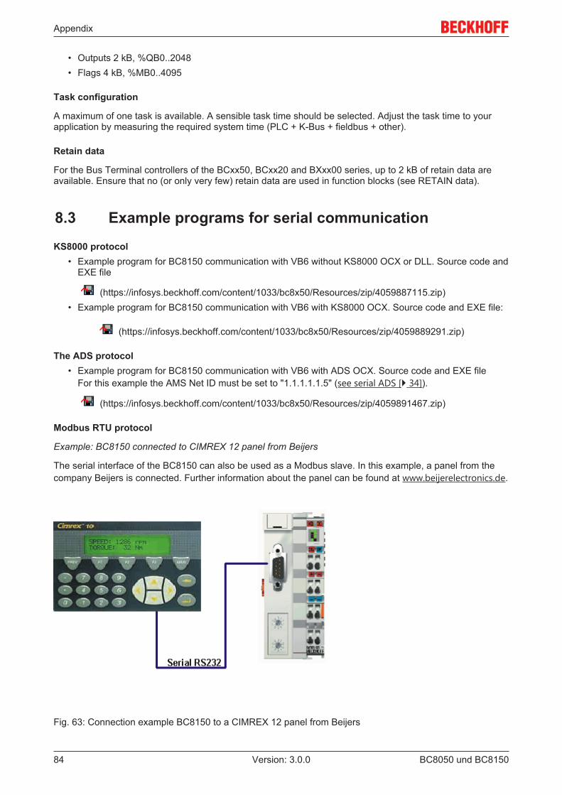
Appendix
BC8050 und BC815084 Version: 3.0.0
• Outputs 2 kB, %QB0..2048• Flags 4 kB, %MB0..4095
Task configuration
A maximum of one task is available. A sensible task time should be selected. Adjust the task time to yourapplication by measuring the required system time (PLC + K-Bus + fieldbus + other).
Retain data
For the Bus Terminal controllers of the BCxx50, BCxx20 and BXxx00 series, up to 2 kB of retain data areavailable. Ensure that no (or only very few) retain data are used in function blocks (see RETAIN data).
8.3 Example programs for serial communication
KS8000 protocol• Example program for BC8150 communication with VB6 without KS8000 OCX or DLL. Source code and
EXE file
(https://infosys.beckhoff.com/content/1033/bc8x50/Resources/zip/4059887115.zip)• Example program for BC8150 communication with VB6 with KS8000 OCX. Source code and EXE file:
(https://infosys.beckhoff.com/content/1033/bc8x50/Resources/zip/4059889291.zip)
The ADS protocol• Example program for BC8150 communication with VB6 with ADS OCX. Source code and EXE file
For this example the AMS Net ID must be set to "1.1.1.1.1.5" (see serial ADS [} 34]).
(https://infosys.beckhoff.com/content/1033/bc8x50/Resources/zip/4059891467.zip)
Modbus RTU protocol
Example: BC8150 connected to CIMREX 12 panel from Beijers
The serial interface of the BC8150 can also be used as a Modbus slave. In this example, a panel from thecompany Beijers is connected. Further information about the panel can be found at www.beijerelectronics.de.
Fig. 63: Connection example BC8150 to a CIMREX 12 panel from Beijers
Appendix
BC8050 und BC8150 85Version: 3.0.0
Necessary components
1 x BC8150 1 x Cimrex 12any Bus Terminals (any, since no Bus Terminals are used in the example)
RS 232 cable
BC8150 COM 1 / RS 232 Cimrex 12 RS 2323 32 25 5
Getting started
Download the example into the BC8150, with an address set between 1 and 39 on the BC8150. Theprogram is loaded to the Bus Terminal controller via serial ADS. Start the PLC program, log off, and removethe programming cable. Load the CIMREX 12 project into the panel and remove the programming cable heretoo. Now connect the Cimrex 12 with the BC8150 using the cable described above. Finally, set slaveaddress 41 on the BC8150. After 10-20 seconds a numerical value should start incrementing on the paneland stop when F2 is pressed on the Cimrex 12.
sample program in ST for BC8150 (any terminal configuration) (https://infosys.beckhoff.com/content/1033/bc8x50/Resources/prx/4059893643.prx)
Example Cimrex 12 panel (https://infosys.beckhoff.com/content/1033/bc8x50/Resources/zip/4059895819.zip)
No libraries are required for the example- baud rate 9600,n,8,1 D- address 41 on the BC8150- Cimrex 12
The ADS protocol
Example: BC8150 connected to CIMREX 12 panel from Beijers
RS 232 cable
BC8150 COM 1 / RS 232 Cimrex 12 RS 2323 32 25 5
sample program in ST for BC8150 (any terminal configuration) (https://infosys.beckhoff.com/content/1033/bc8x50/Resources/prx/4059893643.prx)
Example Cimrex 12 panel (https://infosys.beckhoff.com/content/1033/bc8x50/Resources/zip/4059897995.zip)
8.4 Firmware Update
Firmware update program
The firmware update program is required for loading a new firmware to the Bus Coupler. The program istransferred via the serial interface.
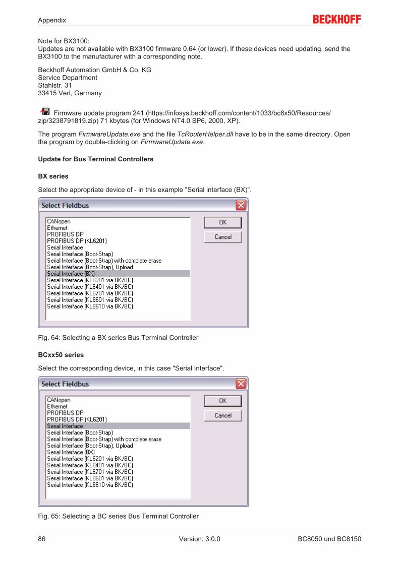
Appendix
BC8050 und BC815086 Version: 3.0.0
Note for BX3100:Updates are not available with BX3100 firmware 0.64 (or lower). If these devices need updating, send theBX3100 to the manufacturer with a corresponding note.
Beckhoff Automation GmbH & Co. KGService Department Stahlstr. 3133415 Verl, Germany
Firmware update program 241 (https://infosys.beckhoff.com/content/1033/bc8x50/Resources/zip/3238791819.zip) 71 kbytes (for Windows NT4.0 SP6, 2000, XP).
The program FirmwareUpdate.exe and the file TcRouterHelper.dll have to be in the same directory. Openthe program by double-clicking on FirmwareUpdate.exe.
Update for Bus Terminal Controllers
BX series
Select the appropriate device of - in this example "Serial interface (BX)".
Fig. 64: Selecting a BX series Bus Terminal Controller
BCxx50 series
Select the corresponding device, in this case "Serial Interface".
Fig. 65: Selecting a BC series Bus Terminal Controller
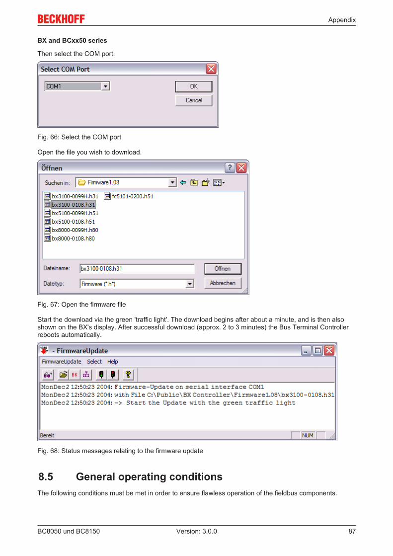
Appendix
BC8050 und BC8150 87Version: 3.0.0
BX and BCxx50 series
Then select the COM port.
Fig. 66: Select the COM port
Open the file you wish to download.
Fig. 67: Open the firmware file
Start the download via the green 'traffic light'. The download begins after about a minute, and is then alsoshown on the BX's display. After successful download (approx. 2 to 3 minutes) the Bus Terminal Controllerreboots automatically.
Fig. 68: Status messages relating to the firmware update
8.5 General operating conditionsThe following conditions must be met in order to ensure flawless operation of the fieldbus components.
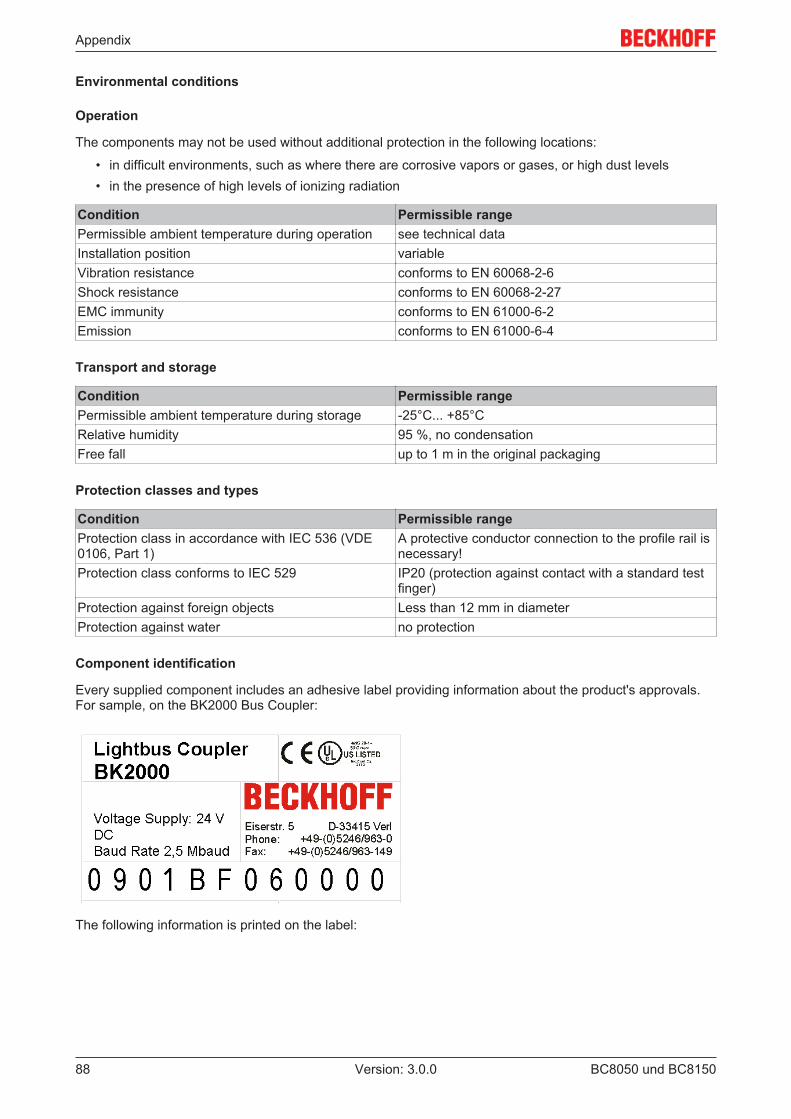
Appendix
BC8050 und BC815088 Version: 3.0.0
Environmental conditions
Operation
The components may not be used without additional protection in the following locations:
• in difficult environments, such as where there are corrosive vapors or gases, or high dust levels• in the presence of high levels of ionizing radiation
Condition Permissible rangePermissible ambient temperature during operation see technical dataInstallation position variableVibration resistance conforms to EN 60068-2-6Shock resistance conforms to EN 60068-2-27EMC immunity conforms to EN 61000-6-2Emission conforms to EN 61000-6-4
Transport and storage
Condition Permissible rangePermissible ambient temperature during storage -25°C... +85°CRelative humidity 95 %, no condensationFree fall up to 1 m in the original packaging
Protection classes and types
Condition Permissible rangeProtection class in accordance with IEC 536 (VDE0106, Part 1)
A protective conductor connection to the profile rail isnecessary!
Protection class conforms to IEC 529 IP20 (protection against contact with a standard testfinger)
Protection against foreign objects Less than 12 mm in diameterProtection against water no protection
Component identification
Every supplied component includes an adhesive label providing information about the product's approvals.For sample, on the BK2000 Bus Coupler:
The following information is printed on the label:
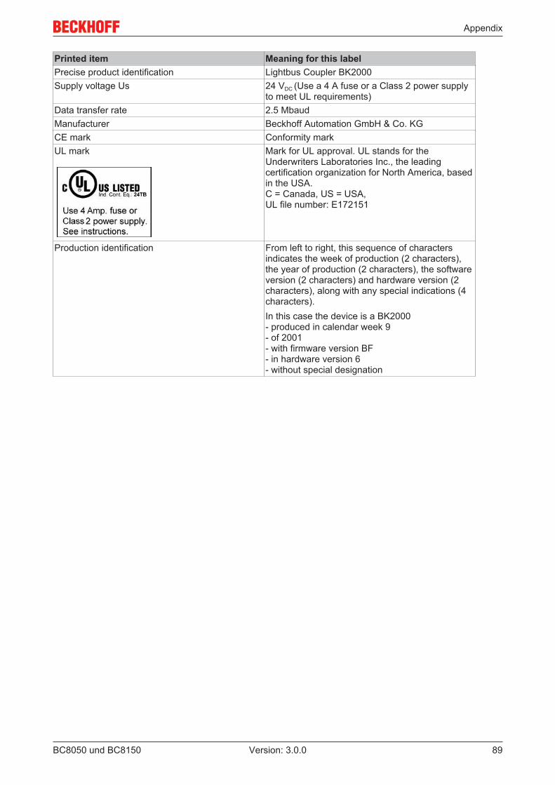
Appendix
BC8050 und BC8150 89Version: 3.0.0
Printed item Meaning for this labelPrecise product identification Lightbus Coupler BK2000Supply voltage Us 24 VDC (Use a 4 A fuse or a Class 2 power supply
to meet UL requirements)Data transfer rate 2.5 MbaudManufacturer Beckhoff Automation GmbH & Co. KGCE mark Conformity markUL mark Mark for UL approval. UL stands for the
Underwriters Laboratories Inc., the leadingcertification organization for North America, basedin the USA.C = Canada, US = USA,UL file number: E172151
Production identification From left to right, this sequence of charactersindicates the week of production (2 characters),the year of production (2 characters), the softwareversion (2 characters) and hardware version (2characters), along with any special indications (4characters).In this case the device is a BK2000- produced in calendar week 9- of 2001- with firmware version BF- in hardware version 6- without special designation
Appendix
BC8050 und BC815090 Version: 3.0.0
8.6 Test standards for device testing
EMC
EMC immunity
EN 61000-6-2
Electromagnetic emission
EN 61000-6-4
Vibration / shock resistance
Vibration resistance
EN 60068-2-6
Shock resistance
EN 60068-2-27
8.7 Bibliography
in preparation
8.8 List of Abbreviations
in preparation
Appendix
BC8050 und BC8150 91Version: 3.0.0
8.9 Support and ServiceBeckhoff and their partners around the world offer comprehensive support and service, making available fastand competent assistance with all questions related to Beckhoff products and system solutions.
Beckhoff's branch offices and representatives
Please contact your Beckhoff branch office or representative for local support and service on Beckhoffproducts!
The addresses of Beckhoff's branch offices and representatives round the world can be found on her internetpages:http://www.beckhoff.com
You will also find further documentation for Beckhoff components there.
Beckhoff Headquarters
Beckhoff Automation GmbH & Co. KG
Huelshorstweg 2033415 VerlGermany
Phone: +49(0)5246/963-0Fax: +49(0)5246/963-198e-mail: [email protected]
Beckhoff Support
Support offers you comprehensive technical assistance, helping you not only with the application ofindividual Beckhoff products, but also with other, wide-ranging services:
• support• design, programming and commissioning of complex automation systems• and extensive training program for Beckhoff system components
Hotline: +49(0)5246/963-157Fax: +49(0)5246/963-9157e-mail: [email protected]
Beckhoff Service
The Beckhoff Service Center supports you in all matters of after-sales service:
• on-site service• repair service• spare parts service• hotline service
Hotline: +49(0)5246/963-460Fax: +49(0)5246/963-479e-mail: [email protected]
List of illustrations
BC8050 und BC815092 Version: 3.0.0
List of illustrationsFig. 1 The principle of the Bus Terminal ................................................................................................ 9Fig. 2 BC8050........................................................................................................................................ 13Fig. 3 BC8150........................................................................................................................................ 14Fig. 4 BCxx50 ........................................................................................................................................ 16Fig. 5 Release the locking mechanism by pulling the orange tab.......................................................... 17Fig. 6 Power contact on the left ............................................................................................................. 17Fig. 7 Potential groups of a Bus Terminal block .................................................................................... 18Fig. 8 Power contact on the left ............................................................................................................. 19Fig. 9 Terminal points for the Bus Terminal Controller supply............................................................... 20Fig. 10 UL identification ........................................................................................................................... 20Fig. 11 Programming cable KS2000-Z2 .................................................................................................. 21Fig. 12 RS232 pin assignment................................................................................................................. 22Fig. 13 Three-core cable with shield, crossed ......................................................................................... 22Fig. 14 RS485 pin assignment................................................................................................................. 23Fig. 15 Two-core cable with shield .......................................................................................................... 23Fig. 16 Start-up behavior of the Bus Terminal Controller ........................................................................ 24Fig. 17 Setting the node ID ...................................................................................................................... 25Fig. 18 Creating a TwinCAT configuration............................................................................................... 28Fig. 19 Selecting the Bus Terminal Controller ......................................................................................... 28Fig. 20 Downloading a TwinCAT configuration........................................................................................ 29Fig. 21 Selecting the Bus Terminal Controller ......................................................................................... 29Fig. 22 State of the Bus Terminal Controller............................................................................................ 29Fig. 23 Activating the TwinCAT configuration.......................................................................................... 30Fig. 24 Choose Target System................................................................................................................ 31Fig. 25 Selecting the Bus Terminal Controller ......................................................................................... 31Fig. 26 State of the Bus Terminal Controller............................................................................................ 31Fig. 27 Uploading the TwinCAT configuration ......................................................................................... 32Fig. 28 Memory for code mapping ........................................................................................................... 32Fig. 29 Data memory mapping ................................................................................................................ 33Fig. 30 Code and data memory ............................................................................................................... 33Fig. 31 Other memory.............................................................................................................................. 34Fig. 32 Properties of the remote connection............................................................................................ 35Fig. 33 Selection dialog "New from Template" ....................................................................................... 36Fig. 34 Selection of Bus Controller ......................................................................................................... 36Fig. 35 "Communication Properties" tab.................................................................................................. 37Fig. 36 Creating variables (inputs, outputs) ............................................................................................. 37Fig. 37 Definition of variables ................................................................................................................. 37Fig. 38 BX Settings tab ............................................................................................................................ 38Fig. 39 BX Diag tab.................................................................................................................................. 39Fig. 40 Maximum number of POUs exceeded......................................................................................... 42Fig. 41 Menu path Projects / Options / Controller Settings...................................................................... 42Fig. 42 Controller settings........................................................................................................................ 43Fig. 43 Global memory insufficient .......................................................................................................... 43Fig. 44 Menu path Projects / Options / Build ........................................................................................... 43
List of illustrations
BC8050 und BC8150 93Version: 3.0.0
Fig. 45 Build............................................................................................................................................. 44Fig. 46 Changing variable links................................................................................................................ 49Fig. 47 Linking a variable with an input.................................................................................................... 49Fig. 48 Opening the options menu........................................................................................................... 52Fig. 49 Selecting Source Download......................................................................................................... 52Fig. 50 Downloading the program code................................................................................................... 53Fig. 51 Download progress ..................................................................................................................... 53Fig. 52 Uploading a program ................................................................................................................... 54Fig. 53 Selecting the data transfer route.................................................................................................. 54Fig. 54 Selecting the device..................................................................................................................... 54Fig. 55 Function block BC8150_SETTINGS............................................................................................ 57Fig. 56 Selecting the data transfer route - serial interface ....................................................................... 61Fig. 57 Parameterization of the serial interface ....................................................................................... 61Fig. 58 Selecting the data transfer route - AMS....................................................................................... 62Fig. 59 Selecting the device..................................................................................................................... 62Fig. 60 Communication library icon ......................................................................................................... 77Fig. 61 State of the K-bus ........................................................................................................................ 79Fig. 62 LEDs ............................................................................................................................................ 80Fig. 63 Connection example BC8150 to a CIMREX 12 panel from Beijers ............................................. 84Fig. 64 Selecting a BX series Bus Terminal Controller............................................................................ 86Fig. 65 Selecting a BC series Bus Terminal Controller............................................................................ 86Fig. 66 Select the COM port .................................................................................................................... 87Fig. 67 Open the firmware file.................................................................................................................. 87Fig. 68 Status messages relating to the firmware update........................................................................ 87