DNV Ship rules Pt.3 Ch.3 - Hull Equipment and Appendages
50
RULES FOR CLASSIFICATION OF DET NORSKE VERITAS Veritasveien 1, N-1322 Høvik, Norway Tel.: +47 67 57 99 00 Fax: +47 67 57 99 11 SHIPS NEWBUILDINGS HULL AND EQUIPMENT MAIN CLASS PART 3 CHAPTER 3 HULL EQUIPMENT AND APPENDAGES JANUARY 2000 CONTENTS PAGE Sec. 1 General Requirements ................................................................................................................ 5 Sec. 2 Sternframes, Rudders and Steering Gears ................................................................................. 6 Sec. 3 Anchoring and Mooring Equipment ........................................................................................ 28 Sec. 4 Masts and Rigging .................................................................................................................... 42 Sec. 5 Seats for Additional Lifting, Towing or Mooring Equipment ................................................ 45 App. A Additional Requirements for non — duplicated Rudder Actuators ........................................ 48
Transcript of DNV Ship rules Pt.3 Ch.3 - Hull Equipment and Appendages

RULES FORCLASSIFICATION OF
DET NORSKE VERITAS
Veritasveien 1, N-1322 Høvik, Norway Tel.: +47 67 57 99 00 Fax: +47 67 57 99 11
SHIPSNEWBUILDINGS
HULL AND EQUIPMENTMAIN CLASS
PART 3 CHAPTER 3
HULL EQUIPMENT AND APPENDAGESJANUARY 2000
CONTENTS PAGE
Sec. 1 General Requirements ................................................................................................................ 5Sec. 2 Sternframes, Rudders and Steering Gears ................................................................................. 6Sec. 3 Anchoring and Mooring Equipment ........................................................................................ 28Sec. 4 Masts and Rigging.................................................................................................................... 42Sec. 5 Seats for Additional Lifting, Towing or Mooring Equipment ................................................ 45App. A Additional Requirements for non — duplicated Rudder Actuators ........................................ 48

CHANGES IN THE RULES
Comments to the rules may be sent by e-mail to [email protected] subscription orders or information about subscription terms, please use [email protected] information about DNV and the Society's services is found at the Web site http://www.dnv.com
© Det Norske VeritasComputer Typesetting (FM+SGML) by Det Norske VeritasPrinted in Norway by GCS AS.
If any person suffers loss or damage which is proved to have been caused by any negligent act or omission of Det Norske Veritas, then Det Norske Veritas shall pay compensation to such personfor his proved direct loss or damage. However, the compensation shall not exceed an amount equal to ten times the fee charged for the service in question, provided that the maximum compen-sation shall never exceed USD 2 million.In this provision "Det Norske Veritas" shall mean the Foundation Det Norske Veritas as well as all its subsidiaries, directors, officers, employees, agents and any other acting on behalf of DetNorske Veritas.
General
The present edition of the rules includes additions and amend-ments decided by the board as of December 1999, and super-sedes the January 1996 edition of the same chapter (includinglater amendments).
The rule changes come into force 1 July 2000.
This chapter is valid until superseded by a revised chapter.Supplements will not be issued except for minor amendmentsand an updated list of corrections presented in Pt.0 Ch.1 Sec.3.Pt.0 Ch.1 is normally revised in January and July each year.Revised chapters will be forwarded to all subscribers to therules. Buyers of reprints are advised to check the updated listof rule chapters printed Pt.0 Ch.1 Sec.1 to ensure that the chap-ter is current.
Main changes
• Sec.3 Anchoring and Mooring Equipment
— In A102 an additional sentence has been added indicating that ifcertification of materials is needed, voluntarily, then this will bedone in accordance with A204.
— In A204 "fibre ropes (W)" has been included in the list of itemsrequiring DNV Product Certificate (NV) for materials, ISO10474: Type 3.1 C. Where the "(W)" indicates that a work's cer-tificate (for materials, ISO 10474 Type 3.1 B) from an approvedmanufacturer will normally be accepted.
• Sec.5 Seats for Additional Lifting, Towing or MooringEquipment
— In A102 it is now stated that the crane pedestal flanges and boltsare only subject to approval when CRANE, DSV or CraneVessel is requested. The amendment is made to remove anymisunderstanding in regard to the material requirements and ap-proval of pedestal flanges and bolts.
— In A301 the material requirement for pedestal top flanges hasbeen removed.
Corrections and Clarifications
In addition to the above stated rule amendments, some detected errorshave been corrected, and some clarifications have been made in theexisting rule wording.

Rules for Ships, January 2000Pt.3 Ch.3 Contents – Page 3
DET NORSKE VERITAS
CONTENTS
SEC. 1 GENERAL REQUIREMENTS .......................... 5
A. Classification..........................................................................5A 100 Application........................................................................5
B. Definitions ..............................................................................5B 100 Symbols.............................................................................5
C. Documentation ......................................................................5C 100 General ..............................................................................5
SEC. 2 STERNFRAMES, RUDDERS AND STEERINGGEARS .................................................................. 6
A. General...................................................................................6A 100 Introduction.......................................................................6A 200 Definitions.........................................................................6A 300 Documentation .................................................................7
B. Materials ................................................................................8B 100 Plates and sections ............................................................8B 200 Forgings and castings........................................................8B 300 Bearing materials ..............................................................8B 400 Material certificates...........................................................8B 500 Heat treatment ...................................................................8
C. Arrangement and Details .....................................................8C 100 Sternframes and rudders....................................................8C 200 Steering gears....................................................................9
D. Design Loads and Stress Analysis........................................9D 100 Rudder force and rudder torque, general .........................9D 200 Rudders with stepped contours .......................................10D 300 Stress analysis .................................................................11
E. Sternframes and Rudder Horns ........................................11E 100 General ............................................................................11E 200 Propeller posts.................................................................11E 300 Sole pieces ......................................................................12E 400 Rudder horns...................................................................12
F. Rudders................................................................................14F 100 General arrangement and details.....................................14F 200 Rudder plating.................................................................14F 300 Rudder bending...............................................................14F 400 Web plates.......................................................................15F 500 Single plate rudders.........................................................15F 600 Mounting of rudder .........................................................15
G. Rudder Stocks and Shafts ..................................................15G 100 General ............................................................................15G 200 Rudder stock with couplings...........................................16G 300 Rudder shaft ....................................................................18G 400 Bearings and pintles .......................................................19
H. Propeller Nozzles.................................................................20H 100 General ............................................................................20H 200 Plating .............................................................................20H 300 Nozzle ring stiffness........................................................20H 400 Welding...........................................................................20H 500 Supports ..........................................................................21
I. Propeller Shaft Brackets ....................................................21I 100 General ............................................................................21I 200 Arrangement....................................................................21I 300 Struts ...............................................................................21I 400 Welding...........................................................................21I 500 Material ...........................................................................21I 600 Testing.............................................................................21
J. Steering Gears .....................................................................21J 100 Arrangement and performance........................................21J 200 Power actuating system, general requirements ...............22J 300 Piping systems, relief valve arrangements......................23J 400 Rudder actuator ...............................................................23J 500 Steering gear control and monitoring systems, general
requirements....................................................................25
J 600 Control gear for steering motors .....................................25J 700 Indications and alarms ...................................................25J 800 Power supply and distribution ........................................25J 900 Emergency power supply................................................26J 1000 Operating instructions.....................................................26J 1100 Additional requirements for oil carriers, chemical carriers
and liquefied gas carriers of 10 000 tons gross andupwards ...........................................................................26
K. Testing ................................................................................. 26K 100 Sternframes .....................................................................26K 200 Rudders and rudder stock connections ...........................27K 300 Steering gears..................................................................27K 400 Trials ...............................................................................27
SEC. 3 ANCHORING AND MOORINGEQUIPMENT .................................................... 28
A. General ................................................................................ 28A 100 Introduction.....................................................................28A 200 Documentation................................................................28A 300 Assumptions....................................................................28
B. Structural Arrangement for Anchoring Equipment ...... 28B 100 General ...........................................................................28
C. Equipment Specification.................................................... 29C 100 Equipment number..........................................................29C 200 Equipment tables.............................................................30
D. Anchors ............................................................................... 31D 100 General ............................................................................31D 200 Materials .........................................................................31D 300 Anchor shackle................................................................31D 400 Testing.............................................................................32D 500 Additional requirements for H.H.P. (“High Holding
Power”) anchors..............................................................32D 600 Identification ...................................................................32
E. Anchor Chain Cables ........................................................ 33E 100 General ............................................................................33E 200 Materials .........................................................................33E 300 Heat treatment and material testing ...............................35E 400 Breaking test ...................................................................35E 500 Proof test .........................................................................35E 600 Tolerances.......................................................................35E 700 Identification ...................................................................36E 800 Repair of defects .............................................................36
F. Windlass and Chain Stoppers .......................................... 38F 100 General design ................................................................38F 200 Materials .........................................................................38F 300 Testing.............................................................................39
G. Towlines and Mooring Lines ............................................ 39G 100 General ............................................................................39G 200 Materials .........................................................................39G 300 Testing of steel wire ropes ..............................................39G 400 Testing of natural fibre ropes..........................................40G 500 Mooring Winches............................................................41
SEC. 4 MASTS AND RIGGING................................... 42
A. General ................................................................................ 42A 100 Introduction.....................................................................42A 200 Assumptions....................................................................42A 300 Definitions.......................................................................42A 400 Documentation................................................................42
B. Materials and Welding ...................................................... 42B 100 Materials .........................................................................42B 200 Welding...........................................................................43
C. Arrangement and Support ................................................ 43C 100 Masts and posts ...............................................................43C 200 Standing rigging..............................................................43

Rules for Ships, January 2000Pt.3 Ch.3 Contents – Page 4
DET NORSKE VERITAS
D. Design and Scantlings.........................................................43D 100 General ............................................................................43D 200 Unstayed masts and posts with derricks .........................43D 300 Stayed masts or posts with derricks with a lifting capacity
not exceeding 10 t ...........................................................43D 400 Stayed masts of posts with derricks with a lifting capacity
of 10 t or more, but not exceeding 40 t ...........................43D 500 Stayed masts without derricks.........................................44D 600 Shrouds............................................................................44
SEC. 5 SEATS FOR ADDITIONAL LIFTING,TOWING OR MOORING EQUIPMENT ...... 45
A. Crane Pedestals and Miscellaneous Lifting Posts............45A 100 Introduction ....................................................................45A 200 Documentation ................................................................45A 300 Materials and welding .....................................................45A 400 Arrangement....................................................................45A 500 Design loads ....................................................................45A 600 Allowable stresses...........................................................46
B. Seatings for Winches, Windlasses and other PullingAccessories...........................................................................46
B 100 Introduction. ....................................................................46B 200 Documentation ................................................................46B 300 Design loads ....................................................................47B 400 Calculation of stresses.....................................................47B 500 Allowable stresses. Materials..........................................47
APP. A ADDITIONAL REQUIREMENTS FOR NON —DUPLICATED RUDDER ACTUATORS ...... 48
A. Introduction......................................................................... 48A 100 Scope ...............................................................................48
B. Materials ..............................................................................48B 100 Special Requirements......................................................48
C. Design................................................................................... 48C 100 Design pressure ...............................................................48C 200 Analysis...........................................................................48C 300 Dynamic loads for fatigue and fracture mechanics
analysis............................................................................48C 400 Allowable stresses...........................................................48C 500 Burst test .........................................................................48
D. Construction Details ...........................................................48D 100 General ............................................................................48D 200 Welds ..............................................................................48D 300 Oil seals...........................................................................48D 400 Isolating valves ...............................................................48D 500 Relief valves....................................................................49
E. Testing.................................................................................. 49E 100 Non-destructive testing ...................................................49E 200 Other testing ....................................................................49

Rules for Ships, January 2000Pt.3 Ch.3 Sec.1 – Page 5
DET NORSKE VERITAS
SECTION 1GENERAL REQUIREMENTS
A. Classification
A 100 Application101 The Rules in this chapter apply to steering arrangementand anchoring, mooring and load handling equipment.
102 Necessary strengthening of the hull structure due toloads imposed by the equipment and installations are givenwhere appropriate.
B. Definitions
B 100 Symbols101
L = Rule length in m 1)
B = Rule breadth in m 1)
D = Rule depth in m 1)
T = Rule draught in m 1)
∆ = Rule displacement in t 1)
CB = Rule block coefficient 1)
V = maximum service speed in knots on draught T
1) For details see Ch.1 Sec.1 B
C. Documentation
C 100 General
101 Plans and particulars to be submitted for approval or in-formation are specified in the respective sections of this chap-ter.
102 For instrumentation and automation, including compu-ter based control and monitoring, see Pt.4 Ch.9 Sec.1.

Rules for Ships, January 2000Pt.3 Ch.3 Sec.2 – Page 6
DET NORSKE VERITAS
SECTION 2STERNFRAMES, RUDDERS AND STEERING GEARS
A. General
A 100 Introduction
101 Requirements to side thrusters and other appliances in-tended for manoeuvring or positioning purposes are given inPt.4 Ch.5.
A 200 Definitions
201 Main steering gear means the machinery, rudder actua-tor(s), the steering gear power units, if any, and ancillaryequipment and the means of applying torque to the rudderstock (e.g. tiller or quadrant) necessary for effecting movementof the rudder for the purpose of steering the ship under normalservice conditions.
202 Auxiliary steering gear means the equipment other thanany part of the main steering gear necessary to steer the ship inthe event of failure of the main steering gear but not includingthe tiller, quadrant or components serving the same purpose.
203 Steering gear control system means the equipment bywhich orders are transmitted from the navigating bridge to thesteering gear power units. Steering gear control systems com-prise transmitters, receivers, hydraulic control pumps and theirassociated motors, motor controllers, piping and cables.
204 Rudder actuator means the component which convertsdirectly hydraulic pressure into mechanical action to move therudder.
205 Steering gear power unit means:
1) in the case of electric steering gear, an electric motor andits associated electrical equipment;
2) in the case of electrohydraulic steering gear, an electricmotor and its associated electrical equipment and connect-ed pump;
3) in the case of other hydraulic steering gear, a driving en-gine and connected pump.
206 Power actuating system means the hydraulic equipmentprovided for supplying power to turn the rudder stock, com-prising a steering gear power unit or units, together with the as-sociated pipes and fittings, and a rudder actuator. The poweractuating systems may share common mechanical compo-nents, i.e. tiller quadrant and rudder stock, or components serv-ing the same purpose.
207 Maximum ahead service speed is the maximum speedcorresponding to maximum nominal shaft RPM and corre-sponding engine MCR in service at sea on summer load water-line.
208 Maximum astern speed is the speed which it is estimatedthe ship can attain at the designed maximum astern power atthe deepest seagoing draught.
209 Maximum working pressure means the maximum oilpressure in the system when the steering gear is operated tocomply with J102.
210 For terms redundancy and independence see Pt.4 Ch.1Sec.1.
211 Some terms used for rudder, rudder stock and supportingstructure are shown in Fig. 1.

Rules for Ships, January 2000Pt.3 Ch.3 Sec.2 – Page 7
DET NORSKE VERITAS
Fig. 1Rudders
212 Symbols:
f1 = material factor, see Bpm = maximum bearing surface pressure, see BFR = design rudder force, see DMTR= design rudder torque, see DA = total area in m2 of rudder bladeH = mean rudder height in m.
A 300 Documentation
301 Plans etc. as specified below are to be submitted for ap-proval:
— sternframe, horn and propeller brackets, outline of the pro-peller
— rudder including details of bearings, shaft, pintles and rud-der lock arrangement
— rudder stock including details of couplings, bolts and keys— rudder carrier— sectional drawing of rudder actuator— dimension drawings for torque transmitting parts and parts
subject to internal hydraulic pressure— foundation bolts and chocks— rudder stoppers— piping (and function) diagram according to Pt.4 Ch.6— schematic diagrams for:
— power supply arrangement— motor control systems (detailed requirements for the
diagrams are given in Pt.4 Ch.8 for electrical installa-tions)
— calculations according to K402 and K403 if sea trials areplanned to be carried out in a load condition not providingfully submerged rudder. Such calculations are at least toinclude evaluation of expected trial loads (torque and sup-
port reaction forces) on the actuator versus calculated rud-der torque fully submerged and at trial conditions takinginto account the friction losses and any back pressure inthe return side.
The plans are to give full details of scantlings and arrangementas well as data necessary for verifying scantling calculationstogether with proposed rated torque. Set pressure for all reliefvalves are to be specified. Material specifications and particu-lars about heat treatment are also required.
302 For important components of welded construction (e.g.rudder, rudder stock, tiller), full details of the joints, weldingprocedure, filler metal and heat treatment after welding are tobe specified on the plans.
303 Procedure for stress relieving of nodular cast iron andcast steel parts, when dimensional stability is important (suchas tiller and rotor, see B502), is to be specified on the plans.
304 Plans of the following items are to be submitted for in-formation:
— general arrangement drawings of steering gear and steer-ing gear compartment
— installation instructions for steering gear (inclusive fittingto rudder stock)
— locking or brake arrangement— steering gear relief valve discharge characteristics (pres-
sure-flow diagram)— total delivery capacity of steering gear hydraulic pumps— operation instructions (according to J1000).
305 Steering gear manufacturers who intend their product tocomply with the requirements of the IMO Guidelines for non-duplicated rudder actuators, see Appendix A, are to submitdocumentation as specified in the guidelines when plans areforwarded for approval.
306 For instrumentation and automation, including compu-ter based control and monitoring, see Pt.4 Ch.9 Sec.1.

Rules for Ships, January 2000Pt.3 Ch.3 Sec.2 – Page 8
DET NORSKE VERITAS
B. Materials
B 100 Plates and sections101 Selection of material grades for plates and sections is tobe based on material thickness. NV-steel grades as given in Ta-ble B1 will normally be accepted.
102 The material factor f1 included in the various formulaefor structures may be taken as:
f1 = 1,0 for NV-NS steel
f1 = 1,08 for NV-27 steel
f1 = 1,28 for NV-32 steel
f1 = 1,39 for NV-36 steel
f1 = 1,43 for NV-40 steel
B 200 Forgings and castings
201 Rudder stocks, pintles, coupling bolts, keys and castparts of rudders are to be made of rolled, forged or cast carbonmanganese steel in accordance with Pt.2.
For rudder stocks, pintles, keys and bolts the minimum yieldstress is not to be less than 200 N/mm2.
202 Nodular cast iron may be accepted in certain parts afterspecial considerations. Materials with minimum specified ten-sile strength lower than 400 N/mm2 or higher than 900 N/mm2
will normally not be accepted in rudder stocks, axle or pintles,keys and bolts.
203 Ram cylinders, pressure housings of rotary vane type ac-tuators, hydraulic power piping, valves, flanges and fittings,and all steering gear components transmitting mechanical forc-es to the rudder stock (such as tillers, quadrants, or similarcomponents) are to be of steel or other approved ductile mate-rial, duly tested in accordance with the requirements of Pt.2. Ingeneral, such material is to have an elongation of not less than12 % nor a tensile strength in excess of 650 N/mm2.
Grey cast iron may be accepted for redundant parts with lowstress level, excluding cylinders, upon special consideration.
204 The material factor f1 for forgings (including rolledround bars) and castings may be taken as:
σf = minimum upper yield stress in N/mm2, not to be takengreater than 70% of the ultimate tensile strength. If notspecified on the drawings, σf is taken as 50% of the ul-timate tensile strength.
a = 0,75 for σf > 235= 1,0 for σf < 235
205 Before significant reductions in rudder stock diameterdue to the application of steels with yield stresses exceeding235 N/mm2 are granted, the Society may require the evaluationof the rudder stock deformations. Large deformations shouldbe avoided in order to avoid excessive edge pressures in wayof bearings. The slope of the stock should be related to thebearing clearance, see G405.
B 300 Bearing materials
301 Bearing materials for bushings are to be stainless steel,bronze, white metal, synthetic material or lignum vitae. Stain-
less steel or bronze bushings are to be used in an approvedcombination with steel or bronze liners on the axle, pintle orstock.
The difference in hardness of bushing and liners is not to beless than 65 Brinell. 13% Chromium steel is to be avoided.
302 Synthetic bearing bushing materials are to be of an ap-proved type. For this type of bushing, adequate supply of lubri-cation to the bearing for cooling/lubrication purposes is to beprovided.
303 The maximum surface pressure pm for the various bear-ing combinations is to be taken as given in Table B2.
Surface pressure exceeding the values in Table B2 may be ac-cepted for rudder actuator bearings in accordance with bearingmanufacturer's specification and when verified by tests.
B 400 Material certificates
401 «Det Norske Veritas Product Certificate» (NV) will berequired for:
— sternframe structural parts— rudder structural parts— rudder shaft or pintles— rudder stock— rudder carrier— tiller or rotor— crosshead— cylinders/rams— rotor housing— manifolds.
402 “Works certificate” (W) will be accepted for:
— bolts and pins— stoppers— steering gear covers— steering gear pistons.
B 500 Heat treatment
501 Fabricated parts in the steering gear are to be fully an-nealed after welding.
502 Nodular cast iron and cast steel parts for transmission ofrudder torque by means of keyless conical or cylindrical con-nections are to be stress relieved.
C. Arrangement and Details
C 100 Sternframes and rudders
101 Relevant types of rudder arrangements are shown in Fig.1. Other combinations of couplings and bearings may be ap-plied.
102 Suitable arrangement to prevent the rudder from liftingand accidental unshipping is to be provided. The arrangement
Table B1 Plate material gradesThickness in mm Normal strength
structural steelHigh strength struc-
tural steelt ≤ 30 A A
30 < t ≤ 40 B A40 < t ≤ 120 D D
f1
σf
235---------
� �� �
a=
Table B2 Bearing surface pressuresBearing material pm (kN/m2)Lignum vitae 2500White metal, oil lubricated 4500Synthetic material with hardness between 60and 70 Shore D 5500 2)
Steel 1) and bronze and hot-pressed bronze-graphite materials 7000
1) Stainless and wear-resistant steel in an approved combination withstock liner
2) Surface pressure exceeding the specified limit may be accepted for rud-der bearing applications in accordance with bearing manufacturer'sspecification and when verified by tests and/or service experience.

Rules for Ships, January 2000Pt.3 Ch.3 Sec.2 – Page 9
DET NORSKE VERITAS
is to effectively limit vertical movement of rudder in case ofextreme (accidental) vertical load on rudder.
103 Effective means are to be provided for supporting theweight of the rudder without excessive bearing pressure, e.g.by a rudder carrier attached to the upper part of the rudderstock. The hull structure in way of the rudder carrier is to besuitably strengthened.
104 If the rudder trunk is open to the sea, a seal or stuffingbox is to be fitted above the deepest load waterline, to preventwater from entering the steering gear compartment and the lu-bricant from being washed away from the rudder carrier.
An additional seal of approved type is required when the rud-der carrier is below the summer load waterline.
105
Guidance note:
The after body should be so shaped as to ensure a proper flow ofwater to the propeller, and so as to prevent uneven formation ofeddies as far as possible. The apex of the waterlines in front ofthe propeller should have the least possible radius, together witha relatively small angle φ. Plane or approximately plane partsabove the propeller tip should be avoided.
The strength of pressure impulses from propeller to hull will nor-mally decrease with increasing clearances. However, even withlarge clearances to the propeller, a hull may be exposed to strongimpulses if the propeller is subject to heavy cavitation.
For a moderately cavitating propeller, the following minimumclearances are proposed (see Table C1 and Fig. 2):
R = propeller radius in mZP = number of propeller blades.
---e-n-d---of---G-u-i-d-a-n-c-e---n-o-t-e---
Fig. 2Propeller clearances
106
Guidance note:
Rudders (one or more) working directly behind a propellershould preferably have a total area not less than:
For ships which frequently manoeuvre in harbours, canals or oth-er narrow waters, the rudder area determined by the formulashould be increased. For ships with a streamlined rudder post,half of the lateral area of the post may be included in the rudderarea. For ships with a rudder horn, the whole area of the horn lay-ing below a horizontal line from the top of the rudder may be in-cluded.
Rudders not working directly behind a propeller should have thearea as given above, increased by at least 30%.
Rudders with special profiles or special configurations (e.g. flapsor nozzles) giving increased efficiency may have smaller total ar-eas.
For ships with large freeboard and/or high continuous super-structures an increase of the rudder area ought to be considered.
Larger rudder area may result in excessive heeling angle whenusing the rudder in extreme position at full speed ahead. This isparticularly relevant for passenger vessels, ferries, vehicle ro/rocarriers and other vessels where the combination of speed,draught, vertical centre of gravity and metacentric height may re-sult in excessive heeling angle in case of smaller turning circles.For estimating the result angle of heel, reference is made to Pt.5Ch.2 Sec.2 K400.
In cases where the resulting angle of heel may exceed 10 degrees,the Master should be provided with warning about this in the sta-bility manual.
---e-n-d---of---G-u-i-d-a-n-c-e---n-o-t-e---
107Guidance note:In order to minimise vibrations, the balancing and design of therudders should be carried out as follows:
— the balanced portion should not be greater than 23% of thetotal area of the rudder
— the length of the balanced part at any horizontal sectionshould nowhere be greater than 35% of the total length ofthe rudder
— the widest part of the rudder section should preferably be atleast 30% aft of the leading edge of the rudder section con-sidered.
---e-n-d---of---G-u-i-d-a-n-c-e---n-o-t-e---
108 Over-balanced rudders are subject to special considera-tion with respect to type of steering gear and risk of an unex-pected and uncontrolled sudden large movement of ruddercausing severe change of ship's pre-set course. See J106.
Guidance note:A rudder shall be considered over-balanced, when balanced por-tion exceed 30% in any actual load condition. Special ruddertypes, such as flap rudders, are subject to special consideration.
---e-n-d---of---G-u-i-d-a-n-c-e---n-o-t-e---
C 200 Steering gears
201 For arrangement and details of steering gear see subsec-tion J.
D. Design Loads and Stress Analysis
D 100 Rudder force and rudder torque, general
101 The rudder force upon which the rudder scantlings are tobe based is to be determined from the following formula:
FR = 0,044 k1 k2 k3 A V2 (kN)
A = area of rudder blade in m2, including area of flap.= vertical projected area of nozzle rudder
Table C1 Minimum clearancesFor single screw ships: For twin screw ships:a ≥ 0,2 R (m)b ≥ (0,7 – 0,04 ZP) R (m)c ≥ (0,48 – 0,02 ZP) R (m) c ≥ (0,6 – 0,02 ZP) R (m)e ≥ 0,07 R (m)
ATL100--------- 1 50CB
2 BL----
� �� �
2+ (m
2 )=
Rules for Ships, January 2000Pt.3 Ch.3 Sec.2 – Page 10
DET NORSKE VERITAS
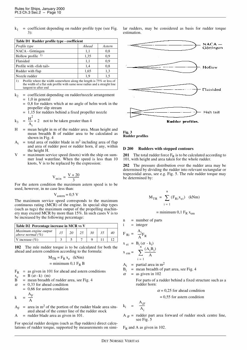
k1 = coefficient depending on rudder profile type (see Fig.3):
k2 = coefficient depending on rudder/nozzle arrangement= 1,0 in general= 0,8 for rudders which at no angle of helm work in the
propeller slip stream= 1,15 for rudders behind a fixed propeller nozzle
k3 = not to be taken greater than 4
H = mean height in m of the rudder area. Mean height andmean breadth B of rudder area to be calculated asshown in Fig. 4
At = total area of rudder blade in m2 including area of flapand area of rudder post or rudder horn, if any, withinthe height H.
V = maximum service speed (knots) with the ship on sum-mer load waterline. When the speed is less than 10knots, V is to be replaced by the expression:
For the astern condition the maximum astern speed is to beused, however, in no case less than:
Vastern = 0,5 V
The maximum service speed corresponds to the maximumcontinuous rating (MCR) of the engine. In special ship types(such as tugs) the maximum output of the propelling machin-ery may exceed MCR by more than 15%. In such cases V is tobe increased by the following percentage:
102 The rule rudder torque is to be calculated for both theahead and astern condition according to the formula:
MTR = FR xe (kNm)
= minimum 0,1 FR B
FR = as given in 101 for ahead and astern conditionsxe = B (α - k) (m)B = mean breadth of rudder area, see Fig. 4α = 0,33 for ahead condition
= 0,66 for astern condition
k =
AF = area in m2 of the portion of the rudder blade area situ-ated ahead of the center line of the rudder stock
A = rudder blade area as given in 101.
For special rudder designs (such as flap rudders) direct calcu-lations of rudder torque, supported by measurements on simi-
lar rudders, may be considered as basis for rudder torqueestimation.
Fig. 3Rudder profiles
D 200 Rudders with stepped contours
201 The total rudder force FR is to be calculated according to101, with height and area taken for the whole rudder.
202 The pressure distribution over the rudder area may bedetermined by dividing the rudder into relevant rectangular ortrapezoidal areas, see e.g. Fig. 5. The rule rudder torque maybe determined by:
= minimum 0,1 FR xem
n = number of partsi = integer
F Ri =
x ei = Bi (α - ki)
x em =
Ai = partial area in m2
Bi = mean breadth of part area, see Fig. 4α = as given in 102
For parts of a rudder behind a fixed structure such as arudder horn:
α = 0,25 for ahead condition
= 0,55 for astern condition
ki =
A iF = rudder part area forward of rudder stock centre line,see Fig. 5
FR and A as given in 102.
Table D1 Rudder profile type - coefficientProfile type Ahead AsternNACA - Göttingen 1,1 0,8Hollow profile 1) 1,35 0,9Flatsided 1,1 0,9Profile with «fish tail» 1,4 0,8Rudder with flap 1,65 1,3Nozzle rudder 1,9 1,51) Profile where the width somewhere along the length is 75% or less of
the width of a flat side profile with same nose radius and a straight linetangent to after end
Table D2 Percentage increase in MCR vs VMaximum engine outputabove normal (%) 15 20 25 30 35 40
V increase (%) 3 5 7 9 11 12
H2
At------ 2+
VminV 20+
3----------------=
AF
A-------
MTR FRixei( ) (kNm)
i 1=
n
�=
Ai
A-----FR
AiBi( )A
----------------
i 1=
n
�
AiF
Ai--------

Rules for Ships, January 2000Pt.3 Ch.3 Sec.2 – Page 11
DET NORSKE VERITAS
Fig. 4Rudder dimensions
Fig. 5Rudder area distribution
D 300 Stress analysis
301 The rudder force and resulting rudder torque as given in100 and 200, causes bending moments and shear forces in therudder body, bending moments and torques in the rudder stock,supporting forces in pintle bearings and rudder stock bearingsand bending moments, shear forces and torques in rudderhorns and heel pieces.
The bending moments, shear forces and torques as well as thereaction forces are to be determined by a direct calculation orby approximate simplified formulae as given in the following.
For rudders supported by sole pieces or rudder horns thesestructures are to be included in the calculation model in orderto account for the elastic support of the rudder body.
Acceptable direct calculation methods are given in Classifica-tion Note No. 32.1 “Strength Analysis of Rudder Arrange-ments”. For rudder horns, see also E404.
302 Allowable stresses for the various strength members aregiven in subsections E to J.
For evaluation of angular deflections, see B205 and G405.
E. Sternframes and Rudder Horns
E 100 General
101 Sternframes and rudder horns are to be effectively at-tached to the surrounding hull structures. In particular the sternbearing or vertical coupling flange for rudder axle is to be ap-propriately attached to the transom floor adjacent to the rudderstock.
For semi-spade and spade rudder arrangements structural con-tinuity in the transverse as well as the longitudinal direction isto be specially observed.
102 Cast steel sternframes and welded sternframes are to bestrengthened by transverse webs.
Castings are to be of simple design, and sudden changes of sec-tion are to be avoided. Where shell plating, floors or otherstructural parts are welded to the sternframe, there is to be agradual thickness reduction towards the joint.
Steel forgings and castings for sternframes, rudder horns andrudders are to be in accordance with the requirements in Pt.2Ch.2 Sec.5 and Sec.7 for general applications.
103 Depending on casting facilities, larger cast steel propel-ler posts are to be made in two or more pieces. Sufficientstrength is to be maintained at connections. The plates of weld-ed propeller posts may be welded to a suitable steel bar at theafter end of the propeller post.
104 Stresses determined by direct calculations as indicatedin D300 are normally not to exceed the following values:
— Normal stress : σ = 80 f1 (N/mm2)— Shear stress : τ = 50 f1 (N/mm2)— Equivalent stress : σe = 120 f1 (N/mm2)
E 200 Propeller posts
201 The boss thickness at the bore for the stern tube is not tobe less than:
dp = rule diameter of propeller shaft in mm.
202 The scantlings of fabricated propeller posts are not to beless than:
l, b and t are as shown in Fig. 6 Alt. I.
Where the section adopted differs from the above, the sectionmodulus about the longitudinal axis is not to be less than:
203 The scantlings of cast steel propeller posts are not to beless than:
σe σ12 σ2
2 σ1σ2– 3τ2+ +=
t 5 dp 60– (mm)=
l 53 L (mm)=
b 37 L (mm)=
t2 4 L,
f1
----------------- (mm)=
ZW1 35L L,
f1------------------------ (cm
3 )=
l 40 L (mm)=
b 30 L (mm)=

Rules for Ships, January 2000Pt.3 Ch.3 Sec.2 – Page 12
DET NORSKE VERITAS
l, b, t1 and t2 are as shown in Fig. 6 Alt. II.
Where the section adopted differs from the above, the sectionmodulus about the longitudinal axis is not to be less than:
When calculating the section modulus, adjoining shell plateswithin a width equal to 53 from the after end of the postmay be included.
Fig. 6Propeller posts
E 300 Sole pieces301 The sole piece is to be sloped in order to avoid pressurefrom keel blocks when docking. The sole piece is to extend atleast two frame spaces forward of forward edge of the propel-ler boss. The cross section of this extended part may be gradu-ally reduced to the cross section necessary for an efficientconnection to the plate keel.
302 The section modulus requirement of the sole piece abouta vertical axis abaft the forward edge of the propeller post isgiven by:
ls = distance in m from the centre line of the rudder stockto the section in question. ls is not to be taken less thanhalf the free length of the sole piece.
303 The section modulus of the sole piece about a horizontalaxis abaft the forward edge of the propeller post is in no placeto be less than:
304 The sectional area of the sole piece is not to be less than:
E 400 Rudder horns
401 The section modulus requirement of the rudder hornabout a longitudinal axis is given by:
lh = vertical distance in m from the middle of the horn pin-tle bearing to the section in question
yh = vertical distance in m from the middle of the rule pintlebearing to the middle of the neck bearing
F Ri = part of rudder force acting on the i-th part of the rudderarea, see D202
y ei = vertical distance in m from the centroid of the i-th partof the rudder area to the middle of the neck bearing
n = number of rudder parts
For the straight part of the rudder horn the section modulusmay be taken for the total sectional area of the horn.
When the connection between the rudder horn and the hullstructure is designed as a curved transition into the hull platingthe section modulus requirement as given above is to be satis-fied by the transverse web plates as follows:
n = number of transverse websbi = effective breadth in mm of web no. i. (including the
flange thickness)ti = thickness in mm of web no. ibmax = largest bi.
Z, bi and bmax are to be taken at a horizontal section 0,7 r abovethe point where the curved transition starts (r = radius ofcurved part, see Fig. 7).
The formula for ZW is based on the material in web plates andshell plate being of the same strength.
For a cast rudder horn any vertical extension of the side plating(see Fig. 8) may be included in the section modulus.
t13 L
f1
----------- (mm)=
t23 7 L,
f1
----------------- (mm)=
ZC1 3L L,
f1--------------------- (cm
3 )=
L
Z1
6 25FRls,f1
----------------------- (cm3 )=
Z2
Z1
2------ (cm
3 )=
AS
0 1FR,f1
---------------- (cm2 )=
Z15MVlh
yhf1-------------------- (cm
3 )=
MV FRiyei
i 1=
n
�=
ZW
bi3ti
i 1=
n
�
6000bmax------------------------ 0 45Z,≥=

Rules for Ships, January 2000Pt.3 Ch.3 Sec.2 – Page 13
DET NORSKE VERITAS
Fig. 7Curved plate transition rudder horn/shell plating
Fig. 8Curved cast transition rudder horn/shell plating
402 The rudder horn thickness requirement is given by:
k =
eh = horizontal projected distance in m from the centre lineof the horn pintle to the centroid of AS
AS = area in cm2 in horizontal section enclosed by the horn.
For a curved transition between horn plating and shell platingthe thickness of the transition zone plate is not to be less than:
s = spacing between transverse webs in mmr = radius of curved transition in mmZA = section modulus at section immediately below the
transition zoneZ = section modulus requirement in same section, as given
in 401.
403 The vertical parts of the rudder horn participating in thestrength against transverse shear are to have a total area in hor-izontal section given by:
C =
= 1,0 at lower endAH = area of horn in m2. At intermediate sections AH should
be taken for part of horn below sectionA = total area of rudder in m2.
In a curved transition zone the thickness of the transverse webplates is not to be less than:
tr = 0,8 tc (mm)
tc = thickness of curved plate
In the transition zone the curved shell plate is to be welded tothe web plates by full penetration weld or by a fillet weld withthroat thickness not less than:
t = 0,55 f1 tr (mm)
404 A direct stress analysis of the rudder horn, if carried out,is to be based on a finite element method.
For a curved transition to the hull structure the maximum al-lowable normal and equivalent stresses as given in 104, may inthe curved plate be increased to:
σ = 120 f1 N/mm2
σe = 180 f1 N/mm2
A fine-mesh finite element calculation will be considered as anacceptable method.
In the web plates the normal stresses should not exceedσ = 130 f1 N/mm2.
405 For a curved transition between the horn side plating andthe shell plating, the side plate thicknesses given in 401 to 404are to be extended to the upper tangent line of the curved part.
t110kFReh
f1AS------------------------- (mm)=
50
4000 1500 Z ZA⁄( )2–
---------------------------------------------------------
tc0 15 s 40–( )2,
r---------------------------------- Z
ZA------- (mm)=
AW C0 3FR,
f1---------------- (cm
2 )=
1A AH+( )AH
A2
--------------------------------+� �� �� �
at upper end of horn

Rules for Ships, January 2000Pt.3 Ch.3 Sec.2 – Page 14
DET NORSKE VERITAS
The transverse web thicknesses are to be kept to the same leveland are to be welded to the floors above. No notches, scallopsor other openings are to be taken in the transition area.
The alternative design is to carry the side plating of the rudderhorn through the shell plate and connect it to longitudinal gird-ers (see Fig. 9), or weld it to the shell plate in line with longi-tudinal girders. In the latter case the welds below and above theshell plate are to be full penetration welds, and the shell plateis to be specially checked for lamellar tearing. The transversegirders are to be connected to/supported by transverse floors.
Floor plating welded to rudder horn web plates is to have athickness not less than 75% of the web plate thickness.
406 The lower end of the rudder horn is to be covered by ahorizontal plate with thickness not less than the side plating.
Fig. 9Shell plating connected to longitudinal girders in line with rudderhorn sides
F. Rudders
F 100 General arrangement and details
101 Rudders are to be double plate type with internal verticaland horizontal web plates.
The rudder body is to be stiffened by horizontal and verticalwebs enabling it to act as a girder in bending.
Single plate rudders may be applied to smaller vessels of spe-cial design and with service restrictions, see 500.
102 All rudder bearings are to be accessible for measuring ofwear without lifting or unshipping the rudder.
Guidance note:In case cover plates are permanently welded to the side plating,it is recommended to arrange peep holes for inspection of secur-ing of nuts and pintles.
---e-n-d---of---G-u-i-d-a-n-c-e---n-o-t-e---
103 Great care is to be taken in highly stressed connectionssuch as:
— welds between rudder side plating and upper heavy part ofrudder at stock coupling
— welds around cut-outs in semi-spade rudders and openingsfor demounting of cone coupling and pintles.
104 Welds between plates and heavy pieces (cast or verythick plating) are to be made as full penetration welds, prefer-ably to cast or welded on ribs. Where back welding is impos-sible welding is to be performed against backing bar orequivalent.
105 Webs are to be connected to the side plates in accord-ance with Ch.1 Sec.12.
Slot-welding is to be limited as far as possible. Horizontal slotsin side plating in areas with large bending stresses are to becompletely filled by welding.
Normally, slots of length 75 mm and a breadth of 2 t (where t= rudder plate thickness), with a distance of 125 mm betweenends of slots, will be accepted. In areas where slots are requiredto be completely filled by welding, more narrow slots with in-clined sides (minimum 15° to the vertical) and a minimumopening of 6 mm at bottom may be used. A continuous slotweld may, however, in such cases be more practical.
106 Plate edges at corners in cut-outs and openings in rudderside plating are to be ground smooth in those parts of the rud-der where high stresses will occur.
107 Means for draining the rudder completely after pressuretesting or possible leakages is to be provided. Drain plugs areto be fitted with efficient packing.
108 Internal surfaces are to be covered by a corrosion-resist-ant coating after pressure-testing and possible stress-relieving.
109 For testing of rudder, see K.
F 200 Rudder plating
201 The thickness requirement of side, top and bottom plat-ing is given by:
ka =
maximum 1,0
s = the smaller of the distances between the horizontal orthe vertical web plates in m
b = the larger of the distances between the horizontal or thevertical web plates in m.
In no case the thickness is to be less than the minimum sideplate thickness as given in Ch.1 Sec.7 C101 or Ch.2 Sec.6C102.
F 300 Rudder bending301 Bending moments in the rudder are to be determined bydirect calculations as indicated in D300.
For some common rudder types the following approximateformulae may be applied:
t5 5,
f1
---------kas T0 1FR,
A----------------+ 2 5 (mm),+=
1 1 0– 5sb---
� �� �
2,,

Rules for Ships, January 2000Pt.3 Ch.3 Sec.2 – Page 15
DET NORSKE VERITAS
— For balanced rudders with heel support:
Mmax = 0,125 FR H (kNm)
— For semi-spade rudders at the horn pintle:
— For spade rudders:
A1 = area in m2 of the rudder part below the cross-section inquestion
hs = vertical distance in m from the centroid of the rudderarea A1 to the section in question.
302 The nominal bending stress distribution in the ruddermay normally be determined on the basis of an effective sec-tion modulus to be estimated for side plating and web plateswithin 40% of the net length (cut-outs or openings deducted)of the rudder profile. The effective length is not to be takengreater than 2,5 ds (ds = rudder stock diameter at neck bearing)or the length of the flange coupling at the top of the rudder.
Special attention to be paid to open flange couplings on therudder. The external transverse brackets will normally have tobe supplied with heavy flanges to obtain the necessary sectionmodulus of the rudder immediately below the flange.
As an alternative the bending stress distribution in the ruddermay be determined by a finite element calculation.
303 Nominal bending stresses calculated as given in 301 and302 are not to exceed:
σ = 110 f1 N/mm2 in general= 75 f1 N/mm2 at sections in way of cut-outs (e.g. semi-
spade rudders) in the rudder.
In case of openings in side plate for access to cone coupling orpintle nut, σ = 90 f1 to be applied when the corner radius isgreater than 0,15 l ( l = length of opening), σ = 60 f1 when theradius is smaller.
F 400 Web plates401 The thickness of vertical and horizontal webs is not to beless than 70% of the thickness requirement given in 200, in nocase less than 8 mm.
402 The total web area requirement for the vertical webs isgiven by:
P =
with heel support
= for spade rudder or lower part of
semi-spade rudderh1 = height in m of the smaller of rudder parts below or
above the cross-section in questionh2 = height in m of the rudder part below the cross section
in question.
Shear stresses in web plates determined by direct stress calcu-lations are not to exceed:
τ = 50 f1 (N/mm2)
Equivalent stress is not to exceed:
σe =
= 120 f1 N/mm2 in rudder-blades without cut-outs= 100 f1 N/mm2 in rudder-blades with cut-outs.
F 500 Single plate rudders
501 Mainpiece diameter
The mainpiece diameter is calculated according to G201. Forspade rudders the lower third may taper down to 0,75 timesstock diameter.
When calculating the rudder force FR as given in D101 the fac-tor k1 may be taken equal to 1,0 in ahead condition.
502 Blade thickness
The blade thickness is not to be less than:
tb = 1,5 s V + 2,5 (mm)
s = spacing of stiffening arms in metres, not to exceed 1 mV = speed in knots, see D101.
503 Arms
The thickness of the arms is not to be less than the blade thick-ness:
ta = tbThe section modulus is not to be less than:
Za = 0,5 s C12 V2 (cm3)
C1 = horizontal distance from the aft edge of the rudder tothe centre line of the rudder stock in metres.
For higher tensile steels the material factor according to B100is to be used correspondingly.
F 600 Mounting of rudder
601 For rudder with continuous shaft it is to be checked thatthe rudder shaft has the right position in relation to the uppercoupling, both longitudinally and transversely, when the lowertapered part of the rudder axle bears hard at the heel. The rud-der shaft is to be securely fastened at the heel before the cou-pling bolts at the upper end are fitted.
602 Before final mounting of rudder pintles, the contact be-tween conical surfaces of pintles and their housings is to bechecked by marking with Prussian blue or by similar method.When mounting the pintles, care is to be taken to ensure thatpackings will not obstruct the contact between mating surfac-es. The pintle and its nut are to be so secured that they cannotmove relatively to each other.
G. Rudder Stocks and Shafts
G 100 General
101 Stresses determined by direct calculations as indicatedin D300 are normally to give equivalent stress σe not exceed-ing 118 f1 N/mm2 and shear stress τ not exceeding 68 f1 N/mm2. The equivalent stress for axles in combined bending andtorsion may be taken as:
σ = bending stress in N/mm2
τ = torsional stress in N/mm2.
102 The requirements to diameters are applicable regardlessof liner. Both ahead and astern conditions are to be considered.
MFRA1hs
A------------------- (kNm)=
Mmax
FRA1hs
A------------------- (kNm)=
AWP
5f1------- (cm
2 )=
0 6h1
H-----–,
� �� � FR for balanced rudder
h2
H-----FR
σb2
3τ2+
σe σ23τ2
+ (N/mm2 )=

Rules for Ships, January 2000Pt.3 Ch.3 Sec.2 – Page 16
DET NORSKE VERITAS
103 A rudder stock cone coupling connection without hy-draulic arrangement for mounting and dismounting is not to beapplied for spade rudders.
104 An effective sealing is to be provided at each end of thecone coupling.
G 200 Rudder stock with couplings201 The diameter requirement is given by:
kb = 1 above the rudder carrier, except where the rudderstock is subjected to bending moment induced by therudder actuator (bearing arrangement versus rudderstock bending deflections, or actuator forces acting ontiller)
=
MB = calculated bending moment in kNm at the section inquestion.
If direct calculations of bending moment distribution are notcarried out, MB at the neck bearing or the rudder coupling maybe taken as follows:
— for balanced rudder with heel support:
— for semi-spade rudder:
— for spade rudder:
MB = FR hs (kNm)
hs = vertical distance in m from the centroid of the rudderarea to the middle of the neck bearing or the coupling.
At the bearing above neck bearing MB = 0, except as follows:
— for rotary vane type actuators with two rotor bearings,which allow only small free deflections, calculation ofbending moment influence may be required if bending de-flection in way of upper bearing exceeds two times dia-metrical bearing clearances at full rudder force FR
— for actuator force induced bending moment the greater ofthe following:
M BU = FA hA (kNm)
or
M BU = PA hA (kNm)
hA =vertical distance between force and bearing centrePA =according to J404M BU =bending moment at bearing above neck bearing.
Minimum diameter of the rudder stock between the neck andthe bearing above is not to be less than if tapered with kb=1,0at the second bearing.
202 Tapered cone connections between rudder stock andrudder and steering gear are to have strength equivalent to thatrequired for rudder stock with respect to transmission of torqueand bending moments as relevant and are to comply with thefollowing:
a) Length/diameter ratio:
b) Hub/shaft diameter ratio D/ds:
c) Taper of cone:
d) Contact surface roughness in micron:
— contact area minimum 70% evenly distributed (seeK200 for control and testing)
— if oil is used for fitting, the design must enable escapeof the oil from between the mating surfaces
— the connection is to be secured by a nut which is prop-erly locked to the shaft.
e) The dimensions at the slugging nut are not to be less than(see Fig. 10):
— external thread diameter:
dg = 0,65 ds— height of nut:
hn = 0,6 dg— outer diameter of nut:
dn = 1,2 dt or dn = 1,5 dg whichever is the greater.
f) Average surface pressure pr due to shrinkage for transmis-sion of torque by means of friction is to be:
T fr = required torque to be transmitted by means of fric-tion in following couplings:
1) Keyless rudder stock connections to:— rudder: 3 MTR— steering gear: 2 Tdes ≤ T fr ≥ 2 MTR
2) Keyed rudder stock connections to:— rudder: 1,5 M TR (0,5 MTR)— steering gear: T fr ≥ TW (0,25 TW)
(figures in parentheses are subject to specialconsideration - see 203)
dm = mean diameter = 0,5 (ds + dt) (mm)l = effective cone length, which may normally be tak-
en as boss length lt, see Fig. 10, (mm)mu = maximum 0,14 for oil injection fitting
= maximum 0,17 for dry fittingMTR = rule rudder torque (kNm), see D102 and D202Tdes = maximum torque corresponding to steering gear
design pressure, or safety valve opening pressure(kNm) - see J404 for calculation of Tdes
Tw = effective steering gear torque at maximum workingpressure (kNm).
ds 42kb
MTR
f1------------
� �� �
13---
(mm)=
143---
MB
MTR------------
� �� �
2+
16---
at arbitrary cross-section
MB
FRH
7----------- (kNm)=
MB
FRH
17----------- (kNm)=
Connection Rudder Steering gearlt/ds ≥ 1,5 ≥ 0,75
Type With key KeylessD/ds ≥ 1,5 ≥ 1,25
Type With key Keylesstaper 1:10 - 1:15 1: ≥ 15
Type of fitting Dry fitted Oil injectionroughness (RA) maximum 3,5 maximum 1,6
pr
2Tfr106
πdm2lµ
------------------- (N/mm2 )≥
Rules for Ships, January 2000Pt.3 Ch.3 Sec.2 – Page 17
DET NORSKE VERITAS
g) The surface pressure (p) used for calculation of pull-uplength is not to be taken less than:
pr ≤ pmin ≥ 1,25 pb (N/mm2)
and is not to exceed:
k = 0,95 for steel forging and cast steel= 0,90 for nodular cast iron= 0,50 for keyed connections.
Variation due to different hub wall thickness is to be con-sidered.
Pressure at the bigger end due to bending moment, Mb,may be taken as:
which may be reduced to zero at a distance l x = 0,5 d or0,5 l (smaller applies) as follows:
p bx = pressure due to bending moment at position xlx = distance from top of cone, see Fig. 10 (mm)dx = ditto shaft diameter at distance lx (mm)Mb = bending moment (kNm).
h) Shrinkage allowance ∆ (mm):
Ei = module of elasticity of shaft (N/mm2)Ee = module of elasticity of hub (N/mm2)νi = Poisson's ratio for shaftνe = Poisson's ratio for hubci = diameter ratio di/d at considered sectionce = diameter ratio d/D at considered sectiondi = diameter of centre bore in shaft (mm)d = shaft diameter at considered section (mm)D = outer diameter of the hub at considered section
(mm).
Minimum shrinkage allowance may be calculated basedon average diameters and the surface pressure (pmin) fromthe above equation.
However, in case hub wall thickness have large variationseither longitudinally or circumferencially this equation isnot valid.
Maximum shrinkage allowance is to be calculated basedon maximum permissible surface pressure (pmax, see g).
i) Pull-up length, minimum:
δmin = K ( ∆min + 2 (R Ai + RAe) 10-3 ) (mm)
δmin ≥ 2 mm for all keyless rudder - rudder stock connec-tions.
j) Pull-up length, maximum:
δmax = K ( ∆max + 2 (R Ai + RAe) 10-3 ) (mm)
δ = pull-up length (mm)
K = taper of the cone = lt/(ds – dt)∆min = calculated minimum shrinkage allowance∆max =calculated maximum shrinkage allowanceR Ai = surface roughness RA of shaft (micron)R Ae = surface roughness RA of hub (micron).
k) Necessary force for pull-up may be estimated as follows:
µ pu = average friction coefficient for pull-up (for oil in-jection (usually in the range 0,01 to 0,03).
203 Tapered key-fitted (keyed) connections are to be de-signed to transmit rudder torque in all normal operating condi-tions by means of friction in order to avoid mutual movementsbetween rudder stock and hub. The key is to be regarded as asecuring device.
For calculation of minimum and maximum pull-up length see202 i) and j).
Where it is not possible or practicable to obtain above requiredminimum pull-up, special attention is to be given to fitting ofthe key in order to ensure tight fit (no free sideways play be-tween key and key-way).
Tapered key-fitted connections are in addition to comply withfollowing:
a) Key-ways shall not be placed in areas with high bendingstresses in the rudder stock and are to be provided with suf-ficient fillet radii (r):
r ≥ 0,01 ds
b) The abutting surface area between the key and key-way inthe rudder stock and hub respectively, is not to be lessthan:
where the torque Tkey is (kNm):
1,5 Tdes – Tfr ≤ Tkey ≥ 2 M TR – Tfr
based on verification of pull-up force, and
1,5 Tdes – 0,7 Tfr ≤ Tkey ≥ 2 MTR – 0,7 Tfr
based on verification of pull-up distance,
but not less than:
Tkey = M TR (kNm).
Yield strength used for calculation of fk is to exceed thelowest of:
σf,key
and
1,5 σf, hub (for calculation of hub) or
1,5 σf, stock (for calculation of stock).
A ab =effective abutting area of the key-way in stockand hub respectively (cm2)
fk =material factor (see B204)σf,hub =yield strength of hub material (N/mm2)σf,key =yield strength of key material (N/mm2)σf,stock=yield strength of stock material (N/mm2).
c) The height/width ratio of the key is to be:
h = height (thickness) of the keyb = width of the key.
pmax kσf
1 ce2
–
3 ce4
+
--------------------- pb (N/mm2 )–≤
pb
3 5Mb,
dml2
-----------------106
(N/mm2 )=
pbx pb18 1lx
0 5dx,--------------–
� �� �� �
(N/mm2 )=
∆ dp
Ee------
1 ce2
+
1 ce2
–----------------- ve+
� �� �� � p
Ei-----
1 ci2
+
1 ci2
–---------------- vi–
� �� �� �
+=
F πdmlpr1
2K------- µpu+
� �� �10
3(kN)≥
Aab
65Tkey
dmfk----------------- (cm
2 )≥
hb--- 0 6,≤

Rules for Ships, January 2000Pt.3 Ch.3 Sec.2 – Page 18
DET NORSKE VERITAS
Where necessary tapered connections are to be provided withsuitable means (e.g. oil grooves and bores to connect hydraulicinjection oil pump) to facilitate dismantling of the hub.
204 Connection between rudder stock and splitted type oftiller or quadrant or rotor are to comply with 202 and 203 as ap-plicable and with the following:
— boss halves are to be joined by at least four bolts (two ineach side)
— one or two keys— cylindrical connections are to be duly secured with regard
to axial loads.
205 Tiller or rotor joined to rudder stock by means of speciallocking assemblies, or by means of tapered connection with in-termediate sleeve, which transmit torque and/or axial forces bymeans of friction alone are to comply with the following:
a)
2,5 Tdes ≤ Tfr ≥ 2,5 MTR
T fr = calculated friction torque.
Tdes and MTR, see 202.
b) When number of locking assemblies is less than three, anarrangement is to be provided to limit drop of the rudderand stock in case of a slip in the friction connection.
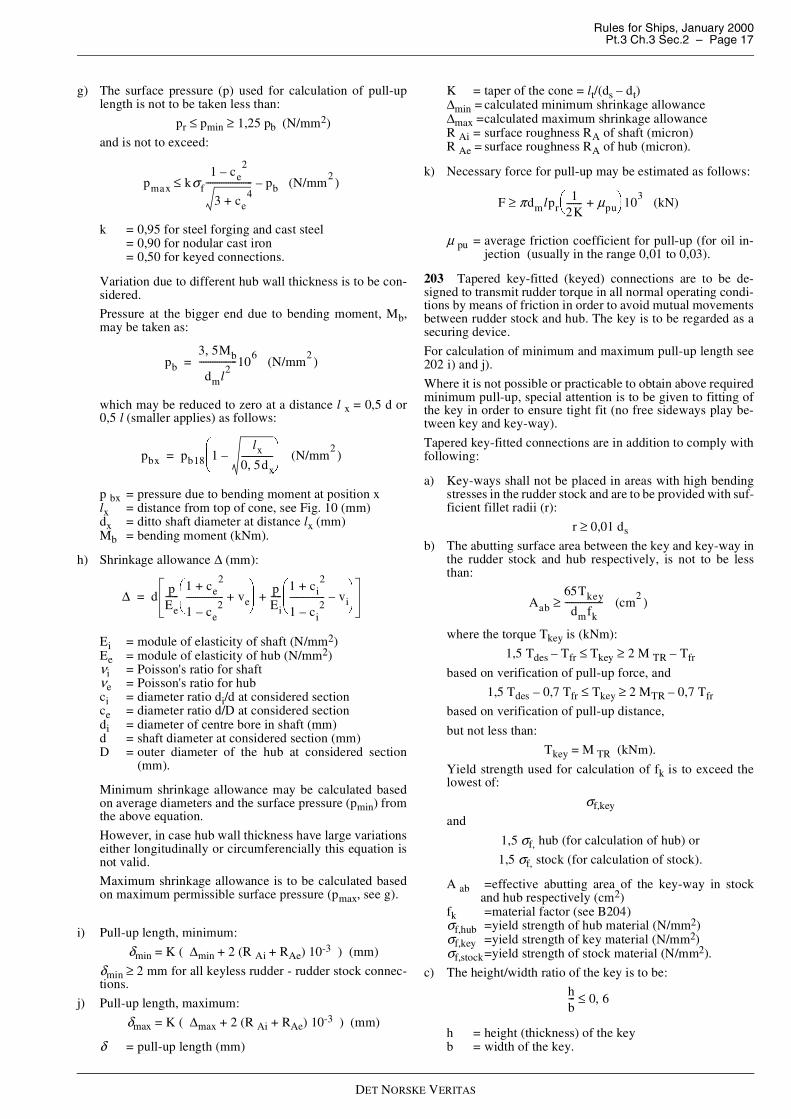
Fig. 10Cone coupling
206 Where the rudder stock is connected to the rudder byhorizontal flange coupling the following requirements are tobe complied with:
a) At least 6 coupling bolts are to be used.
b) The diameter of coupling bolts is not to be less than:
ds = rule diameter of rudder stock at coupling flange inmm as given in 201
n = number of coupling boltse = mean distance in mm from the centre of bolts to the
centre of the bolt systemf ms = material factor (f1) for rudder stockf mb = material factor (f1) for bolts.
c) Nuts are to be securely fastened by split pins or other effi-cient means.
d) If the coupling is subjected to bending stresses, the meandistance a from the centre of the bolts to the longitudinalcentre line of the coupling is not to be less than 0,6 ds.
e) The width of material outside the bolt holes is not to beless than 0,67 db.
f) The thickness of coupling flanges is not to be less than thegreater of:
db = bolt diameter, calculated for a number of bolts notexceeding 8
f mf = material factor (f1) for flange,
or
MB = bending moment in kNm at couplinga = mean distance from centre of bolts to the longitudi-
nal centre line of the coupling, in mmd = diameter as built of rudder stock for stock flange,
breadth of rudder for rudder flange, both in mmβ = factor to be taken from the following table:
Ample fillet radius is to be in accordance with recognisedstandards.
G 300 Rudder shaft
301 At the lower bearing, the rudder shaft diameter is not tobe less than:
c =
l, a and b are given in Fig. 11 in m.
The diameter df below the coupling flange is to be 10% greaterthan dl. If, however, the rudder shaft is protected by a corro-sion-resistant composition above the upper bearing, df may beequal to dl.
302 The taper, nut, etc. at lower end of rudder shafts, is to betaken as for rudder stock given in 202.
303 The scantlings of the vertical coupling at the upper endof the rudder shaft are to be as required for horizontal ruddercouplings in 206, inserting the shaft dl instead of the stock di-ameter ds in the formula for bolt diameter.
db 0 62ds
3fms
nefmb---------------- (mm),=
d/a 0,8 0,9 1,0 1,1 1,2 1,3 1,4 1,5 1,6β 1,8 1,5 1,25 1,0 0,8 0,6 0,45 0,35 0,25
t db
fmb
fmf-------- , minimum 0,9db (mm)=
t 70βMB
afmf------------ (mm)=
dl 39FRc l c–( )
lf1-------------------------
� �� �
13---
(mm)=
a b+2
------------

Rules for Ships, January 2000Pt.3 Ch.3 Sec.2 – Page 19
DET NORSKE VERITAS
Fig. 11Rudder shaft
G 400 Bearings and pintles401 The height of bearing surfaces is to be taken not greaterthan:
hb = 1,2 dsl (mm)
dsl = diameter in mm of rudder shaft or pintle measured onthe outside of liners.
402 The bearing surface area is not to be less than:
AB = hb dslhb and dsl = as given in 401P = calculated reaction force in kN at the bearing in
questionpm = maximum surface pressure as given in B303.
If direct calculations of reaction forces are not carried out, P atvarious bearings may be taken as given in the following (notethat values given for stern pintle or neck bearing in semi-spaderudders are minimum values):
a) For balanced rudder with heel support:
P = 0,6 FR (kN) at heel pintle bearing
P = 0,7 FR (kN) at stern pintle or neck bearing
P = 0,1 FR (kN) at upper bearing.
b) For semi-spade rudder (The horn pintle bearing is assumedto be situated not more than 0,1 H above or below the cen-troid of the rudder):
P = 1,1 FR (kN) at horn pintle bearing
Pmin = 0,4 FR (kN) at stern pintle or 0,3 FR (kN) at neckbearing
P = 0,1 FR (kN) at upper bearing.
c) For spade rudder:
(kN) at neck bearing
(kN) at upper bearing
h1 = vertical distance from the centroid of rudder area tothe middle of the neck bearing
h2 = vertical distance from the middle of the neck bear-ing to the middle of the upper bearing.
403 The diameter of pintles is not to be less than:
P = as given in 402.
404 The thickness of any bushings in rudder bearings is notto be less than:
minimum 8 mm for steel and bronze,
maker's specification for synthetic materials,
minimum 22 mm for Lignum Vitae,
other materials are to be especially considered.
P = as given in 402.
The bushing is to be effectively secured to the bearing. Thethickness of bearing material outside of the bushing is not tobe less than:
P = as given in 402.
405 With metal bearings the clearance on the diameter isnormally not to be less than:
0,001 db + 1,0 (mm)
db=inner diameter in mm of the bushing.
If non-metallic bearing material is applied, the bearing clear-ance is to be specially determined considering the materials'swelling and thermal expansion properties. This clearance isnot to be taken less than 1,5 mm on the bearing diameter.
ABP
Pm------- 10
6(mm
2 )=
Ph1 h2+
h2-----------------FR=
Ph1
h2-----FR=
dp 10 Pf1---- (mm)=
tv 0 32 P (mm),=
t 2 0 Pf1---- (mm),=
Rules for Ships, January 2000Pt.3 Ch.3 Sec.2 – Page 20
DET NORSKE VERITAS
For spade rudders with large bending moment and inducedslope at the neck bearing the clearance should be related to thecalculated angular deflection over the bearing length.
Due attention should, however, be given to the manufacturer'srecommended clearance. For pressure lubricated bearings theclearance will be especially considered.
406 Pintles are to have a conical attachment to the gudgeons.The various dimensions (taper, nut, key) are to be as requiredfor rudder stock in 202 and 203 inserting the pintle diameter dpinstead of the stock diameter ds in the various formulae.
The bending moment, MB may be taken as pintle force P mul-tiplied by the height from 1/3 of height of bearing to 1/2 of thelength of cone and MTR may be taken as 0,00025 dbP.
db = inner diameter of bushing (mm).
The length of pintle housing is not to be less than the pintle di-ameter and the thickness of material outside the bushing is notto be less than 0,25 db.
An effective sealing against sea water is to be provided at bothends of the cone.
H. Propeller Nozzles
H 100 General101 The following requirements are applicable to fixed andsteering nozzles of inner diameter 4 metres or less.
Guidance note:The requirements may also be applied for the initial design ofnozzles with diameter exceeding 4 metres.In that case the scantlings and arrangement should be speciallyconsidered with respect to exciting frequencies from the propel-ler.
---e-n-d---of---G-u-i-d-a-n-c-e---n-o-t-e---
H 200 Plating201 The thickness of the nozzle shell plating in the propellerzone is not to be less than:
where:
N = 0,01 PS D, need not be taken greater than 100PS = maximum continuous output (kW) delivered to the
propellerD = inner diameter (m) of nozzles = distance in m between ring webs, is not to be taken less
than 0,35 metres in the formulaka = aspect ratio correction as given in F201, to be applied
when longitudinal stiffeners.
The thickness in zone I and II is not to be less than 0,7 t and inzone III not less than 0,6 t, corrected for spacing s.
The propeller zone is to be taken minimum 0,25 b (where b =length of nozzle). For steering nozzles the propeller zone is tocover the variations in propeller position.
On the outer side of the nozzle, zone II is to extend beyond theaftermost ring web.
202 The thickness of ring webs and fore and aft webs is notto be taken less than 0,6 t. They are to be increased in thicknessin way of nozzle supports.
203 If the ship is reinforced according to an ice class nota-tion, the part of the outer shell of the nozzle which is situatedwithin the ice belt is to have a plate thickness not less than cor-
responding to the ice class requirement for the after part of theship.
Guidance note:In order to prevent corrosion and erosion of the inner surface ofthe nozzle, application of a corrosion resistant material in thepropeller zone is recommended. All but welds should be groundsmooth.
When a corrosion resistant material is used, the plate thicknessmay be reduced by 15%.
---e-n-d---of---G-u-i-d-a-n-c-e---n-o-t-e---
H 300 Nozzle ring stiffness
301 In order to obtain a satisfactory stiffness of the nozzlering the following requirement is to be fulfilled:
I = 2,8 k b D3 V2 (cm4)
I = moment of inertia of nozzle section about the neutralaxis parallel to centre line
k =
tm = mean thickness of nozzle inner and outer shell plating(mm), in propeller plane
b = length of nozzle, see Fig. 12, in mD = as given in 201V = maximum service speed (knots)n = number of ring webs.
Fig. 12Section through nozzle ring
302 If the ship is reinforced according to an ice class notationthe parameter V for the requirement in 301 is not to be takenless than:
V = 14, 15, 16 and 17 knots for ice class 1C, 1B, 1A and1A*, respectively.
H 400 Welding
401 The inner shell plate is to be welded to the ring webswith double continuous fillet welding.
402 The outer shell plate is as far as possible to be weldedcontinuously to the ring webs. Slot welding may be acceptedon the following conditions:
If the web spacing s ≤ 350 mm all welds to outer plating maybe slot welds. If the web spacing s > 350 mm at least two ringwebs are to be welded continuously to the outer shell. A con-tinuous weld according to Fig. 13 may be accepted.
403 Slot welds are to have a slot length l not less than 75 mmand a breadth equal to 2t (t = nozzle shell plate thickness),maximum 30 mm. More narrow slots may be applied whereslots are completely filled by welding. The distance betweenslots (from centre to centre) is not to exceed 2
l, maximum 250 mm. The slot weld throat thickness is normal-ly to be 0,7 t.
t 10 3kasNf1---- (mm)+=
28b
Dtm n 1+( )--------------------------------

Rules for Ships, January 2000Pt.3 Ch.3 Sec.2 – Page 21
DET NORSKE VERITAS
H 500 Supports
501 The nozzle is to be supported by at least two supports.The web plates and shell plates of the support structure are tobe in line with web plates in the nozzle.
Fig. 13Connection nozzle shell plate/ring web
I. Propeller Shaft Brackets
I 100 General
101 The following requirements are applicable to propellershaft brackets having two struts to support the propeller tailshaft boss. The struts may be of solid or welded type.
102 The angle between the struts is not to be less than 50 de-grees.
I 200 Arrangement
201 Solid struts are to be carried continuously through theshell plating and are to be given satisfactory support by the in-ternal ship structure.
202 Welded struts may be welded to the shell plating. Theshell plating is to be reinforced, and internal brackets in linewith strut plating are to be fitted. If the struts are built with alongitudinal centre plate, this plate is to be carried continuous-ly through the shell plating. The struts are to be well roundedat fore and aft end at the transition to the hull.
203 The propeller shaft boss is to have well rounded fore andaft brackets at the connection to the struts.
204 The strut structure inside the shell is to terminate withina compartment of limited volume to reduce the effect of flood-ing in case of damage.
I 300 Struts
301 Solid or built-up struts of propeller shaft brackets are tocomply with the following requirements:
h = 0,4 d (mm)
A = 0,4 d2 (mm2)
W = 0,12 d3 (mm3)
A = area of strut sectionW = section modulus of section. W is to be calculated with
reference to the neutral axis Y-Y as indicated on Fig.14
h = the greatest thickness of the sectiond = Propeller shaft diameter in mm.
The diameter refers to shaft made of steel with a minimumspecified tensile strength of 430 N/mm2.
Fig. 14Strut section
I 400 Welding
401 Welding between struts and hull and propeller shaft bossis to be made as full penetration welds.
402 For welded construction full details of the joints, weld-ing procedure, filler metal and heat treatment after welding areto be specified on the plans.
I 500 Material
501 Regarding material of brackets reference is made to sub-section B.
I 600 Testing
601 Ultrasonic and magnetic particle examination of thewelds is to be carried out on the brackets and at the shell pen-etrations.
J. Steering Gears
J 100 Arrangement and performance
101 Unless expressly provided otherwise, every ship shall beprovided with a main steering gear and an auxiliary steeringgear to the satisfaction of the requirements in the Rules. Themain steering gear and the auxiliary steering gear shall be soarranged that the failure of one of them will not render the oth-er one inoperative.
102 The main steering gear and rudder stock shall be:
a) of adequate strength and capable of steering the ship atmaximum ahead service speed which shall be demonstrat-ed
b) capable of putting the rudder over from 35° on one side to35° on the other side with the ship at its deepest seagoingdraught and running ahead at maximum ahead servicespeed and, under the same conditions, from 35° on eitherside to 30° on the other side in not more than 28 seconds(20 seconds for class notation Tug or Supply Vessel,see Pt.5 Ch.7 Sec.2 and Sec.3 and ice classes: ICE 05-15,POLAR 10-30 and 15 seconds for Icebreaker, see Pt.5Ch.1 Sec.4)
c) operated by power where necessary to meet the require-ments in b) and in any case when the rules require a rudderstock of over 120 mm diameter in way of the tiller, exclud-ing strengthening for navigation in ice
d) so designed that they will not be damaged at maximumastern speed.
103 The auxiliary steering gear shall be:
a) of adequate strength and capable of steering the ship atnavigable speed and of being brought speedily into actionin an emergency
b) capable of putting the rudder over from 15° on one side to15° on the other side in not more than 60 seconds with theship at its deepest seagoing draught and running ahead atone half of the maximum ahead service speed or 7 knots,whichever is the greater
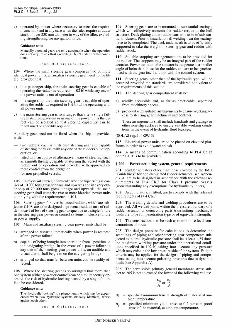
Rules for Ships, January 2000Pt.3 Ch.3 Sec.2 – Page 22
DET NORSKE VERITAS
c) operated by power where necessary to meet the require-ments in b) and in any case when the rules require a rudderstock of over 230 mm diameter in way of the tiller, exclud-ing strengthening for navigation in ice.
Guidance note:Manually operated gears are only acceptable when the operationdoes not require an effort exceeding 160 N under normal condi-tions.
---e-n-d---of---G-u-i-d-a-n-c-e---n-o-t-e---
104 Where the main steering gear comprises two or moreidentical power units, an auxiliary steering gear need not be fit-ted, provided that:
a) in a passenger ship, the main steering gear is capable ofoperating the rudder as required in 102 b) while any one ofthe power units is out of operation
b) in a cargo ship, the main steering gear is capable of oper-ating the rudder as required in 102 b) while operating withall power units
c) the main steering gear is so arranged that after a single fail-ure in its piping system or in one of the power units the de-fect can be isolated so that steering capability can bemaintained or speedily regained.
Auxiliary gear need not be fitted when the ship is providedwith:
— two rudders, each with its own steering gear and capableof steering the vessel with any one of the rudders out of op-eration, or
— fitted with an approved alternative means of steering, suchas azimuth thruster, capable of steering the vessel with therudder out of operation and provided with approved re-mote control from the bridge or
— for non-propelled vessels.
105 In every oil carrier, chemical carrier or liquefied gas car-rier of 10 000 tons gross tonnage and upwards and in every oth-er ship of 70 000 tons gross tonnage and upwards, the mainsteering gear shall comprise two or more identical power unitscomplying with the requirements in 104.
106 Steering gears for over-balanced rudders, which are sub-ject to C108, are to be designed to prevent a sudden turn of rud-der in case of loss of steering gear torque due to a single failurein the steering gear power or control systems, inclusive failurein power supply.
107 Main and auxiliary steering gear power units shall be:
a) arranged to restart automatically when power is restoredafter a power failure
b) capable of being brought into operation from a position onthe navigating bridge. In the event of a power failure toany one of the steering gear power units, an audible andvisual alarm shall be given on the navigating bridge
c) arranged so that transfer between units can be readily ef-fected.
108 Where the steering gear is so arranged that more thanone system (either power or control) can be simultaneously op-erated, the risk of hydraulic locking caused by a single failureis to be considered.
Guidance note:The “hydraulic locking” is a phenomenon which may be experi-enced when two hydraulic systems (usually identical) worksagainst each other.
---e-n-d---of---G-u-i-d-a-n-c-e---n-o-t-e---
109 Steering gears are to be mounted on substantial seatings,which will effectively transmit the rudder torque to the hullstructure. Deck plating under rudder carrier is to be of substan-tial thickness. Prior to installation all welding near the seatingshave to be completed. The deck underneath is to be efficientlysupported to take the weight of steering gear and rudder withrudder stock.
110 Suitable stopping arrangements are to be provided forthe rudder. The stoppers may be an integral part of the rudderactuator. Power cut-out to the actuator is to operate at a smallerangle of helm than those for the rudder, and are to be synchro-nised with the gear itself and not with the control system.
111 Steering gears, other than of the hydraulic type, will beaccepted provided the standards are considered equivalent tothe requirements of this section.
112 The steering gear compartment shall be:
a) readily accessible and, as far as practicable, separatedfrom machinery spaces
b) provided with suitable arrangements to ensure working ac-cess to steering gear machinery and controls.
These arrangements shall include handrails and gratings orother non-slip surfaces to ensure suitable working condi-tions in the event of hydraulic fluid leakage.
(SOLAS reg. II-1/29.13)
113 Electrical power units are to be placed on elevated plat-forms in order to avoid water splash.
114 A means of communication according to Pt.4 Ch.12Sec.2 B101 is to be provided.
J 200 Power actuating system, general requirements
201 Rudder actuators other than those covered by the IMO“Guidelines” for non-duplicated rudder actuators, see Appen-dix A, are to be designed in accordance with the relevant re-quirements of Pt.4 Ch.7 for Class I pressure vessels(notwithstanding any exemptions for hydraulic cylinders).
202 Accumulators, if fitted, are to comply with the relevantrequirements of Pt.4 Ch.7.
203 The welding details and welding procedures are to beapproved. All welded joints within the pressure boundary of arudder actuator or connecting parts transmitting mechanicalloads are to be full penetration type or of equivalent strength.
204 The construction is to be such as to minimise local con-centrations of stress.
205 The design pressure for calculations to determine thescantlings of piping and other steering gear components sub-jected to internal hydraulic pressure shall be at least 1,25 timesthe maximum working pressure under the operational condi-tions specified in 102 b) taking into account any pressurewhich may exist in the low pressure side of the system. Fatiguecriteria may be applied for the design of piping and compo-nents, taking into account pulsating pressures due to dynamicloads (see Appendix A).
206 The permissible primary general membrane stress sub-ject to 205 is not to exceed the lower of the following values:
σb = specified minimum tensile strength of material at am-bient temperature
σy = specified minimum yield stress or 0,2 per cent proofstress of the material, at ambient temperature.
σb
A------ or
σy
B------

Rules for Ships, January 2000Pt.3 Ch.3 Sec.2 – Page 23
DET NORSKE VERITAS
A and B are given by the following table:
207 Special consideration is to be given to the suitability ofany essential component which is not duplicated. Any such es-sential component shall, where appropriate, utilise anti-frictionbearings such as ball bearings, roller bearings or sleeve bear-ings which shall be permanently lubricated or provided withlubrication fittings.
208 All steering gear components transmitting mechanicalforces to the rudder stock, which are not protected againstoverload by structural rudder stops or mechanical buffers, areto have a strength at least equivalent to that of the rule rudderstock in way of the tiller.
209 Oil seals between non-moving parts, forming part of theexternal pressure boundary, should be of the metal upon metaltype or of an equivalent type.
210 Oil seals between moving parts, forming part of the ex-ternal pressure boundary, should be duplicated, so that the fail-ure of one seal does not render the actuator inoperative.Alternative arrangements providing equivalent protectionagainst leakage may be accepted.
211 Hydraulic power operated steering gears are to be pro-vided with:
a) arrangements to maintain the cleanliness of the hydraulicfluid taking into consideration the type and design of thehydraulic system
b) a fixed storage tank having sufficient capacity to rechargeat least one power actuating system including the reser-voir, where the main steering gear is required to be poweroperated. The storage tank is to be permanently connectedby piping in such a manner that the hydraulic systems canbe readily recharged from a position within the steeringgear compartment and provided with a contents gauge.
212 Hydraulic power supply for steering gear is not to beused for other purposes.
J 300 Piping systems, relief valve arrangements
301 Piping, joints, valves, flanges and other fittings are tocomply with the requirements of Pt.4 Ch.6. Power piping is tocomply with requirements to class I pipes. The design pressureis to be in accordance with 205.
302 For all vessels with non-duplicated actuators, isolatingvalves, directly fitted on the actuator, are to be provided at theconnection of pipes to the actuator.
303 Main and auxiliary steering gear are to be provided withseparate hydraulic power supply pipes. When main steeringgear is arranged in accordance with 104, each hydraulic powerunit is to be provided with separate power pipes. Interconnec-tions between power pipes are to be provided with quick oper-ating isolating valves.
304 Arrangements for bleeding air from the hydraulic sys-tem are to be provided, where necessary.
305 Relief valves are to be fitted to any part of the hydraulicsystem which can be isolated and in which pressure can begenerated from the power source or from external forces. Thesetting of the relief valves is not to exceed the design pressure.The valves are to be of adequate size and so arranged as toavoid an undue rise in pressure above the design pressure.
306 Relief valves for protecting any part of the hydraulicsystem which can be isolated, as required in 305 are to complywith the following:
a) The setting pressure is not to be less than 1,25 times themaximum working pressure.
b) The minimum discharge capacity of the relief valve(s) isnot to be less than 110 per cent of the total capacity of thepumps which can deliver through it (them). Under suchconditions the rise in pressure is not to exceed 10 per centof the setting pressure. In this regard, due consideration isto be given to extreme foreseen ambient conditions in re-spect of oil viscosity.
307 Flexible hoses of approved type may be installed be-tween two points where flexibility is required but are not to besubjected to torsional deflection (twisting) under normal oper-ating conditions. In general, the hose should be limited to thelength necessary to provide for flexibility and for proper oper-ation of machinery.
308 Hoses are to be high pressure hydraulic hoses accordingto recognised standards and suitable for the fluids, pressures,temperatures and ambient conditions in question. For detailedrequirements for construction and testing of flexible hoses, seePt.4 Ch.6 Sec.6 D.
J 400 Rudder actuator
401 The actuator housing may be cast or welded construc-tion. Parts subjected to internal pressure are to satisfy the de-sign requirements in 200.
402 The structural design is to be chosen with due respect totransmission of reaction forces to the seatings.
403 The rudder carrier, or in case of an integral unit, the rud-der actuator and its fastening to foundations, is to be able totake reaction forces due to bending set up in rudder stock. Sidechocks may be required in addition to fitted bolts.
404 The permissible equivalent stress in tiller arms, rotorvanes, stoppers, piston rods, rams, guides and other similarparts, where calculations are based on the rule rudder torque,MTR is:
and where calculated at the design pressure:
For certain parts, which are not subject to reversed load, per-missible stress at the design pressure may be increased to:
Permissible bending stress in rotor vanes calculated at designpressure is:
Fillets are to be smooth and well rounded to give reasonablelow stress concentrations (geometrical stress concentration(factor) ≤1,5).
Relevant stresses due to pretensioning of bolts, or shrink fittingof hubs, etc. are to be duly considered.
σe = permissible von Mises equivalent stress in N/mm2
σf = yield strength of the material in N/mm2 (see B200)f1 = material factor, see B204σfit = static stress due to pretension or shrinkage in N/mm2.
Tangential shrink fitting stress at the hub surface may be takenas follows:
Table J1 Permissible primary membrane stressSteel Cast steel Nodular cast iron
AB
3,51,7
42
53
σe 118f1 1σfit
σf--------–
� �� � (N/mm
2 )≤
σe 150f1 1σfit
σf--------–
� �� � (N/mm
2 )≤
σe 185f1 1σfit
σf--------–
� �� � (N/mm
2 )≤
σb 1 5σAB 1σfit
σf--------–
� �� � (N/mm
2 ),≤

Rules for Ships, January 2000Pt.3 Ch.3 Sec.2 – Page 24
DET NORSKE VERITAS
σb = permissible bending stress in N/mm2
σAB = smaller of the or in 206
p = actual pressure due to shrinkage in N/mm2 (seeG200).
Average hub thickness in way of vanes shall normally not beless than 70% of required vane root thickness.
Design torqueTdes of a rudder actuator for calculation of rud-der stock connection is to be taken as:
Tdes is not to exceed:
p = steering gear design pressure (MPa)n = number of active pistons or vanesA = piston or vane (projected) area (mm2)l = torque arm (m), see Fig. 15θ = rudder angle
= 0°C for rotary vane and linked cylinder type actuator= maximum permissible rudder angle (normally 35°) for
ram type actuatorΦ = as defined in Fig. 15
= 0° for ram and rotary vane type actuatord = rudder stock minimum diameter below tiller or rotor
(mm)kb = bending moment factor, see G201.
The shearing force based on rule rudder torque in each of thearms or vanes may be expressed as:
Corresponding bending moment at the root of arms or vanesmay be expressed as:
The effective shear area of arms or vanes is, however, not to beless than (greater of the values applies):
l = length of tiller arm measured from centre of rudderstock to point of action of driving force in m
n = number of arms or vanes (not to be taken greater than3)
d = diameter of tiller boss, in md so = rule diameter of rudder stock at tiller, see G200, in mmM TR = rule rudder torque, see D200.
The value of l will depend on the design of the tiller or rotorand also on the angle of helm as illustrated in Fig. 15.
405 Hydraulic cylinder type actuators are to comply with re-quirements for buckling strength given in Pt.4 Ch.6.
Fig. 15Steering gears
σfit p1 ce
2+
1 ce2
–----------------- 1–
� �� �� �
(N/mm2 )=
σb
A------
σy
B------
TdespnAl Φcos
θcos--------------------------10
3–(kNm)=
Tdes 2f1d
42kb-----------
� �� � 3
(kNm)=
PA
MTR
nl------------ (kN)=
MA PA l d2---–
� �� � (kNm)=
AA
dso3
5000nl----------------- or
pA50f1---------- (mm
2 )=

Rules for Ships, January 2000Pt.3 Ch.3 Sec.2 – Page 25
DET NORSKE VERITAS
J 500 Steering gear control and monitoring systems,general requirements
501 For instrumentation and automation, including compu-ter based control and monitoring, the requirements in thischapter are additional to those given in Pt.4 Ch.9.
502 Steering gear control system is the equipment by whichorders are transmitted from the navigation bridge to the steer-ing gear power units. Steering gear control systems comprisetransmitters, receivers, hydraulic control pumps and their asso-ciated motors, motor controllers, piping and cables.
503 Steering gear control shall be provided:
a) for the main steering gear, both on the navigating bridgeand in the steering gear compartment
b) where the main steering gear is arranged in accordancewith 104 by two independent control systems, both opera-ble from the navigating bridge. This does not require du-plication of the steering wheel or steering lever. Where thecontrol system consists of an hydraulic telemotor, a sec-ond independent system operable from the bridge need notbe fitted, except in an oil carrier, chemical carrier or lique-fied gas carrier of 10 000 tons gross and upwards
c) for the auxiliary steering gear, in the steering gear com-partment and, if power operated, it shall also be operablefrom the navigating bridge and shall be independent of thecontrol system for the main steering gear.
504 Any main and auxiliary steering gear control system op-erable from the navigating bridge shall comply with the fol-lowing:
a) If electric, it shall be served by its own separate circuitsupplied from a steering gear power circuit from a pointwithin the steering gear compartment, or directly fromswitchboard busbars supplying that steering gear powercircuit at a point on the switchboard adjacent to the supplyto the steering gear power circuit.
b) Means shall be provided in the steering gear compartmentfor disconnecting any control system operable from thenavigating bridge from the steering gear it serves.
c) The system shall be capable of being brought into opera-tion from a position on the navigating bridge.
d) In the event of a failure of electrical power supply to thecontrol system, an audible and visual alarm shall be givenon the navigating bridge.
e) Short circuit protection only shall be provided for steeringgear control supply circuits.
505 The electric power circuits and the steering gear controlsystems with their associated components, cables and pipes areto be separated as far as is practicable throughout their length.
506 When two or more exclusive electric control systems areused, these are to be kept separated with separate cables andare not to be located in the same enclosure. Regarding arrange-ments in steering stands, this requirement may be waived, pro-vided the systems are securely installed and separated as far aspracticable.
Steering order devices for exclusive electric control systemsmay be operated by the same wheel or lever shaft.
Steering mode and steering station selectors for exclusive elec-tric systems may also be operated by the same shaft, providedthe arrangement is of reliable construction.
507 If additional steering stations are arranged with controlcircuits branched off from a main steering station, it is to bepossible to disconnect each such circuit by a multipole switchon the main steering station.
J 600 Control gear for steering motors
601 Steering gear motors are to be provided with controlgear according to requirements given in Pt.4 Ch.8. The controlgear is, however, not to have overcurrent or other overload re-leases.
602 Steering gear motors are to be remote controlled fromthe bridge and local controlled from the steering gear compart-ment. When remote control is arranged from two or more po-sitions, the arrangement is to be such that the motor can bestarted independently from any of these positions.
603 The control circuit of each steering gear motor is to besuch that a motor in operation will restart automatically uponrestoration of voltage after a power failure.
J 700 Indications and alarms
701 Alarm and indication requirements are specified in Ta-ble J2.
702 All alarms associated with steering gear faults are to beindicated on the navigating bridge and in machinery spacewhere they can be readily observed.
703 The rudder angle indicating system is to be independentof any control system and so arranged that a single failure inpower supply or anywhere in the indication system does notcause loss of rudder angle indication on the bridge.
704 Where hydraulic locking, caused by a single failure,may lead to loss of steering, an alarm, which identifies thefailed system, is to be provided.
Guidance note:This alarm should be activated when there is disagreement be-tween the given order versus control system output/execution.For instance when:
— position of the variable displacement pump control systemdoes not correspond with given order; or
— incorrect position of 3-way full flow valve or similar in con-stant delivery pump system is detected.
---e-n-d---of---G-u-i-d-a-n-c-e---n-o-t-e---
J 800 Power supply and distribution
801 Power supply is to be arranged with redundancy. Forships where main source of electric power is arranged withoutredundancy, the steering gear is to be arranged in such a waythat steering from the bridge will be possible also after loss ofmain electric power, e.g. by means of direct hand-hydraulicsteering.
802 At least two exclusive circuits are to be provided foreach electric or electrohydraulic steering gear arrangementcomprising one or more power units.
803 Each of the exclusive circuits is to be fed from the mainswitchboard, however, one circuit may pass through the emer-gency switchboard.
804 One of these circuits may supply an associated auxiliaryelectric or electrohydraulic steering gear.
805 Each of these circuits is to have adequate capacity tosupply all motors which may be connected and operated simul-taneously.
806 In ships of less than 1600 gross tonnage, if provided withan auxiliary steering gear independent of electrical power sup-ply, the main steering gear may be fed by one circuit from themain switchboard.
807 Where the rudderstock is required to be over 230 mm di-ameter (excluding ice strengthening) in way of the tiller, an al-ternative power supply shall be provided automatically within45 seconds, either from the emergency source of electrical

Rules for Ships, January 2000Pt.3 Ch.3 Sec.2 – Page 26
DET NORSKE VERITAS
power or from an independent source of power located in thesteering gear compartment.
J 900 Emergency power supply901 Where the rudder stock is required to be over 230 mmdiameter in way of the tiller, excluding strengthening for nav-igation in ice, an alternative power supply, sufficient at least tosupply the steering gear power unit which complies with therequirements in 103 and also its associated control system andthe rudder angle indicator, shall be provided automatically,within 45 seconds, either from the emergency source of elec-trical power or from an independent source of power located inthe steering gear compartment. This independent source ofpower shall be used only for this purpose.
902 In every ship of 10 000 gross tonnage and upwards, thealternative power supply shall have a capacity for at least 30minutes of continuous operation and in any other ship for atleast 10 minutes.
903 Where the alternative power source is a generator, or anengine driven pump, starting arrangements are to comply withthe requirements relating to the starting arrangements of emer-gency generators.
J 1000 Operating instructions1001 Appropriate operating instructions with a block dia-gram showing the change-over procedures for steering gearcontrol systems and steering gear actuating systems are to bepermanently displayed in the wheelhouse and in the steeringgear compartment.
1002 Where the system failure alarms according to 704 areprovided, appropriate instructions are to be given to shut downthe failed system.
J 1100 Additional requirements for oil carriers, chemicalcarriers and liquefied gas carriers of 10 000 tons gross andupwards1101 Every oil carrier, chemical carrier or liquefied gas car-rier of 10 000 tons gross and upwards are, subject to 1102 tocomply with the following:
a) The main steering gear is to be so arranged that in theevent of loss of steering capability due to a single failurein any part of one of the power actuating systems of themain steering gear, excluding the tiller, quadrant or com-ponents serving the same purpose, or seizure of the rudderactuators, steering capability is to be regained in not morethan 45 seconds after the loss of one power actuating sys-tem.
b) The main steering gear is to comprise either:
— two independent and separate power actuating sys-tems, each capable of meeting the requirements in 102b), or
— at least two identical power actuating systems which,acting simultaneously in normal operation, are to becapable of meeting the requirements in 102 b). Wherenecessary to comply with this requirement, inter-con-nection of hydraulic power actuating systems is to beprovided. Loss of hydraulic fluid from one system isto be capable of being detected and the defective sys-tem automatically isolated so that the other actuatingsystem or systems are to remain fully operational.
c) Steering gears other than of the hydraulic type are toachieve equivalent standards.
1102 For oil carriers, chemical carriers or liquefied gas car-riers of 10 000 tons gross and upwards, but of less than 100 000tonnes deadweight, solutions other than those set out in 1101,which need not apply the single failure criterion to the rudderactuator or actuators, may be permitted provided that an equiv-alent safety standard is achieved and that:
a) following loss of steering capability due to a single failureof any part of the piping system or in one of the powerunits, steering capability is to be regained within 45 sec-onds, and
b) where the steering gear includes only a single rudder actu-ator, special consideration is given to stress analysis forthe design including fatigue analysis and fracture mechan-ics analysis, as appropriate, to the material used, to the in-stallation of sealing arrangements and to testing andinspection and to the provision of effective maintenance.In consideration of the foregoing, regard will be given tothe IMO «Guidelines» for non-duplicated rudder actua-tors, given in Appendix A.
K. Testing
K 100 Sternframes
101 Built sternframes with closed sections are to be pressuretested on completion.
Table J2 Monitoring requirements for steering gear
Item AlarmIndication
Remarkssubject position
Rudder position Rudder angle Bridge and steering gearcompartment
Steering gear power units Power failure Phase failureMotor overload
Running Bridge and machineryspace
Steering gear Hydraulic lock Shall identify failed sys-tem
Steering gear control sys-tem
Power failure Ready for operation Dis-connection of bridge con-trol system
Bridge Low pressure alarm is re-quired when control sys-tem is not integrated in themain system
Steering gear hydraulicsystem oil tanks (each - in-clusive steering controlsystem tanks)
Low level Low level alarm indicationis not to be combined withother alarms on the bridge1)
Storage tank Oil level Content gauge on the tankAuto pilot Failure Running Bridge Alarm on bridge only1) Low level alarm in separate steering gear control system oil tanks may be substituted by low pressure alarm. It is provided that each of the systems is able
to control the main steering gear alone, and that oil leakage in one system has no effect on the other one
Rules for Ships, January 2000Pt.3 Ch.3 Sec.2 – Page 27
DET NORSKE VERITAS
K 200 Rudders and rudder stock connections
201 Contact area of conical connections is to be (minimum70%) verified by means of paint test (e.g. tool-maker blue) inpresence of the surveyor.
202 Test pull-up followed by control of contact area may berequired before final assembly for conical keyless connectionsintended for injection fitting, if calculations are considered in-accurate due to a non-symmetric design or other relevant rea-sons. Pull-up length during test pull-up is not to be less thanfinal pull-up length.
K 300 Steering gears
301 The requirements of the rules relating to the testing ofclass I pressure vessels, piping, and related fittings apply. Testpressure for internal pressure testing is to be 1,5 times the de-sign pressure.
302 After installation on board the vessel the steering gear isto be subjected to the required hydrostatic and running tests.
303 On double rudder installation where the two units aresynchronised by mechanical means, mutual adjustment is to betested.
304 For testing and certification of hydraulic, electrical andinstrumentation and/or automation parts and systems, see Pt.4Ch.6, Pt.4 Ch.8 and Pt.4 Ch.9, respectively.
305 Each type of power unit pump is to be subjected to a typetest. The type test shall be for a duration of not less than 100hours, the test arrangements are to be such that the pump mayrun in idling conditions, and at maximum delivery capacity atmaximum working pressure. During the test, idling periods areto be alternated with periods at maximum delivery capacity atmaximum working pressure. The passage from one conditionto another should occur at least as quickly as on board. Duringthe whole test no abnormal heating, excessive vibration or oth-er irregularities are permitted. After the test, the pump is to bedismantled and inspected. Type tests may be waived for a pow-er unit which has been proven to be reliable in marine service.
K 400 Trials
401 The steering gear is to be tried out on the trial trip in or-der to demonstrate to the surveyor's satisfaction that the re-quirements of the rules have been met. (The designrequirement given in J102 d) need not be proved by trials atmaximum astern speed and maximum rudder angles.) The trialis to include the operation of the following:
a) Trial conditions:
— loaded on summer load waterline— running ahead at maximum service speed correspond-
ing to maximum nominal shaft RPM and maximumcontinuous rating (MCR) of the main engine(s) and ifequipped with controllable pitch propeller(s), the pro-peller pitch is to be at the maximum design pitch cor-responding to the nominal shaft RPM and MCR of themain engine(s).
If the vessel cannot be tested on summer load water-line, alternative trial conditions may be specially con-sidered. See 402 and 403.
a1) Main steering gear trial:
— turning the rudder over from 35° on one side to 35° onthe other side and vice versa
— from 35° on either side to 30° on the other sides re-spectively within required time as given in J102, or ifclass notation Tug, Supply Vessel, or Ice ClassesICE 05-15 or POLAR 10-30, or Icebreaker in therespective rule sections.
Where main steering gear comprises two or moreidentical power units, the steering gear is to be testedwith each power unit individually and all together,provided these are intended for simultaneous running.For capacity versus number of power units in opera-tion, see J104.
a2) Auxiliary steering gear trial:
— turning the rudder over from 15° on one side to 15° onthe other side in not more than 60 seconds with theship on summer load waterline and running ahead atone half of the maximum ahead service speed or 7knots, whichever is the greater.
b) the steering gear power units, including transfer betweensteering gear power units
c) the isolation of one power actuating system, checking thetime for regaining steering capability
d) the hydraulic fluid recharging system
e) the emergency power supply required in J900
f) the steering gear controls, including transfer of control andlocal control
g) the means of communication between the steering gearcompartment and the wheelhouse, also the engine room, ifapplicable
h) the alarms and indicators
i) where steering gear is designed to avoid hydraulic lockingthis feature shall be demonstrated.
Test items d), g) and h) may be effected at the dockside.
402 When performance test is carried out with reduceddraught with partly submerged rudder, calculations showingcorresponding rudder force and torque for the trials are to besubmitted on request.
403 Ships fitted with semi-spade rudders are normally to betested with the rudders completely submerged. However, whensatisfactory results are proved by sister ships, tests accordingto 402 with partly submerged rudder may be accepted. Calcu-lations of the expected rudder force and torque for the trials areto be submitted. If test results for sisterships are not available,steering gear test with rudder partly submerged may be accept-ed upon special consideration in each case.

Rules for Ships, January 2000Pt.3 Ch.3 Sec.3 – Page 28
DET NORSKE VERITAS
SECTION 3ANCHORING AND MOORING EQUIPMENT
A. General
A 100 Introduction101 The requirements in this section apply to equipment andinstallation for anchoring and mooring.
102 Towlines and mooring lines are not subject to classifica-tion. Lengths and breaking strength are, however, given in theequipment tables as guidance. If certification of materials isneeded voluntarily, it shall be done in accordance with 204.
A 200 Documentation201 The following plans and particulars are to be submittedfor approval:
— equipment number calculations— equipment (list) including type of anchor, grade of anchor
chain, type and breaking load of steel and fibre ropes— anchor design if different from standard or previously ap-
proved anchor types. Material specification— windlass design. Material specifications for cable lifters,
shafts, couplings and brakes— chain stopper design. Material specification.
202 The following plans and particulars are to be submittedfor information:
— arrangement of deck equipment.
203 For barges the towline fastening arrangement and de-tails, stating towing force is to be submitted for approval.
204 Det Norske Veritas Product Certificate (NV) (for mate-rials, ISO 10474: Type 3.1 C) will be required for the follow-ing items:
— anchor and anchor shackle— anchor chain cable and accessories (shackles, swivels,
etc.)— windlass cable lifter— winch drum and drum flanges— shafts for cable lifter and/or drum— pawl wheel, stopper and couplings— gear shafts and wheels (W)— windlass/winch frame work (W)— brake components— chain stopper— steel wire ropes (W)— fibre ropes (W).
For items above marked with (W), work's certificate (for ma-terials, ISO 10474: Type 3.1 B) from approved manufacturerwill normally be accepted.
A 300 Assumptions301 The anchoring equipment required is the minimum con-sidered necessary for temporary mooring of a vessel in moder-ate sea conditions when the vessel is awaiting berth, tide, etc.The equipment is therefore not designed to hold a vessel offfully exposed coasts in rough weather or for frequent anchor-ing operations in open sea. In such conditions the loads on theanchoring equipment will increase to such a degree that itscomponents may be damaged or lost owing to the high energyforces generated.
Guidance note:If the intended service of the vessel is such that frequent anchor-ing in open sea is expected, it is advised that the size of anchorsand chains is increased above the rule requirements, taking into
account the dynamic forces imposed by the vessel moving inheavy seas. The Equipment Numeral (EN) formula for requiredanchoring equipment is based on an assumed current speed of 2,5m/s, wind speed of 25 m/s and a scope of chain cable between 6and 10, the scope being the ratio between length of chain paid outand water depth.
---e-n-d---of---G-u-i-d-a-n-c-e---n-o-t-e---
302 The anchoring equipment required by the Rules is de-signed to hold a vessel in good holding ground in conditionssuch as to avoid dragging of the anchor. In poor holdingground the holding power of the anchors will be significantlyreduced.
303 It is assumed that under normal circumstances the vesselwill use only one bower anchor and chain cable at a time.
B. Structural Arrangement for AnchoringEquipment
B 100 General
101 The anchors are normally to be housed in hawse pipes ofsuitable size and form to prevent movement of anchor andchain due to wave action.
The arrangements are to provide an easy lead of the chain cablefrom the windlass to the anchors. Upon release of the brake,the anchor is immediately to start falling by its own weight. Atthe upper and lower ends of hawse pipes, there are to be chaf-ing lips. The radius of curvature is to be such that at least 3links of chain will bear simultaneously on the rounded parts atthe upper and lower ends of the hawse pipes in those areaswhere the chain cable is supported during paying out and hoist-ing and when the vessel is laying at anchor. Alternatively, roll-er fairleads of suitable design may be fitted.
Where hawse pipes are not fitted alternative arrangements willbe specially considered.
102 The shell plating in way of the hawse pipes is to be in-creased in thickness and the framing reinforced as necessary toensure a rigid fastening of the hawse pipes to the hull.
103 Ships provided with a bulbous bow, and where it is notpossible to obtain ample clearance between shell plating andanchors during anchor handling, local reinforcements of bul-bous bow are to be provided as necessary.
104 The chain locker is to have adequate capacity and a suit-able form to provide a proper stowage of the chain cable, andan easy direct lead for the cable into the chain pipes, when thecable is fully stowed. Port and starboard cables are to have sep-arate spaces. If 3 bower anchors and 3 hawse pipes are used,there are to be 3 separate spaces. The chain locker boundariesand access openings are to be watertight. Provisions are to bemade to minimise the probability of chain locker being floodedin bad weather. Adequate drainage facilities of the chain lockerare to be adopted.
Provisions are to be made for securing the inboard ends ofchain to the structure. This attachment is to be able to with-stand a force of not less than 15% nor more than 30% of theminimum breaking strength of the chain cable. The fasteningof the chain to the ship is to be made in such a way that in caseof emergency when anchor and chain have to be sacrificed, thechain can be readily made to slip from an accessible positionoutside the chain locker.

Rules for Ships, January 2000Pt.3 Ch.3 Sec.3 – Page 29
DET NORSKE VERITAS
105 The windlass and chain stoppers are to be efficientlybedded to the deck. The deck plating in way of windlass andchainstopper is to be increased in thickness and supported bypillars carried down to rigid structures. See Sec.5 B.
C. Equipment Specification
C 100 Equipment number
101 The equipment number is given by the formula:
E N = ∆2/3 + 2 B H + 0,1 A
H = effective height in m from the summer load waterlineto the top of the uppermost deckhouse, to be measuredas follows:
H = a + Σ hi
a = distance in m from summer load waterline amidshipsto the upper deck at side
hi = height in m on the centre line of each tier of houseshaving a breadth greater than B/4. For the lowest tier,hi is to be measured at centre line from the upper deck,or from a notional deck line where there is local dis-continuity in the upper deck
A = area in m2 in profile view of the hull, superstructuresand houses above the summer load waterline, which iswithin L of the ship. Houses of breadth less than B/4are to be disregarded.
In the calculation of Σ hi and A sheer and trim are to be ig-nored.
Windscreens or bulwarks more than 1,5 m in height are to beregarded as parts of superstructures and of houses when deter-mining H and A. The total area of the mentioned items meas-ured from the deck, is to be included.
The area of hatch coamings more than 1,5 m in height abovedeck at side is to be included in A.
102 For a barge rigidly connected to a push-tug the equip-ment number is to be calculated for the combination regardedas one unit.
Table C1 Equipment table, general
Equipmentnumber
Equip-mentletter
Stockless boweranchors Stud-link chain cables Towline
(guidance)Mooring lines 1)
(guidance)
Number
Massper an-
chor
kg
Totallength Diameter and steel grade Steel or fibre ropes Steel or fibre ropes
m
NVK1
mm
NVK2
mm
NVK3
mm
Mini-mum
lengthm
Minimumbreakingstrength
kN
Number
Lengthof each
m
Minimumbreakingstrength
kN30-4950-6970-89
90-109
a0abc
2222
120180240300
192,5220220
247,5
12,51416
17,5
12,51416
170180180180
88,598,098,098,0
2333
8080100110
32343739
110-129130-149150-174
def
222
360420480
247,5275275
1920,522
17,517,519
180180180
989898
333
110120120
444954
175-204205-239240-279
ghi
222
570660780
302,5302,5330
242628
20,52224
20,522
180180180
112129150
344
120120120
596469
280-319320-359360-399
jkl
222
90010201140
357,557,5385
303234
262830
242426
180180180
174207224
444
140140140
747888
400-449450-499500-549
mno
222
129014401590
385412,5412,5
363840
323434
283030
180180190
250277306
444
14040160
98108123
550-599600-659660-719
pqr
222
174019202100
440440440
424446
363840
323436
190190190
338371406
444
160160160
132147157
720-779780-839840-909
stu
222
228024602640
467,5467,5467,5
485052
424446
363840
190190190
441480518
444
170170170
172186201
910-979980-1059
1060-1139
vwx
222
285030603300
495495495
545658
485050
424446
190200200
559603647
444
170180180
216230250
1140-12191220-12991300-1389
yzA
222
354037804050
522,5522,5522,5
606264
525456
464850
200200200
691738786
444
180180180
270284309
1390-14791480-15691570-1669
BCD
222
432045904890
550550550
666870
586062
505254
200220220
836888941
455
180190190
324324333
1670-17891790-19291930-2079
EFG
222
525056106000
577,5577,5577,5
737678
646668
565860
220220220
102411091168
555
190190190
353378402
2080-22292230-23792380-2529
HIJ
222
645069007350
605605605
818487
707376
626466
240240240
125913561453
555
200200200
422451480
2530-26992700-28692870-3039
KLM
222
780083008700
632,5632,5632,5
909295
788184
687073
260260260
147114711471
666
200200200
480490500

Rules for Ships, January 2000Pt.3 Ch.3 Sec.3 – Page 30
DET NORSKE VERITAS
C 200 Equipment tables
201 The equipment is in general to be in accordance with therequirements given in Table C1.
The two bower anchors and their cables are to be connectedand stowed in position ready for use. The total length of chaincable required is to be equally divided between the two an-chors. The towline and the mooring lines are given as guidanceonly, representing a minimum standard, and are not to be con-sidered as conditions of class.
202 For fishing vessels the equipment is to be in accordancewith the requirements given in Table C2. When the equipmentnumber is larger than 720, table C1 should be applied.
203 Unmanned barges are only to have equipment consistingof 2 mooring lines with length as required by Table C1.
204 For ships and manned barges with restricted service theequipment specified in Table C1 and C2 may be reduced in ac-cordance with Table C3. No reductions are given for class no-tations R0 and R1.
205 For ships and manned barges with equipment numberEN less than 205 the anchor and chain equipment specified inTable C1 and C2 may be reduced, on application from theOwners, based upon a special consideration of the intendedservice area of the vessel. The reduction is not to be more thangiven for the service notation R4 in Table C3. In such cases aminus sign will be given in brackets after the equipment letterfor the vessel in the “Register of vessels classed with DNV”,e.g. f(–).
3040-32093210-33993400-3599
NOP
222
93009900
10500
660660660
97100102
848790
767878
280280280
147114711471
666
200200200
520554588
3600-37993800-39994000-4199
QRS
222
111001170012300
687,5687,5687,5
105107111
929597
818487
300300300
147114711471
667
200200200
618647647
4200-43994400-45994600-4799
TUV
222
129001350014100
715715715
114117120
100102105
879092
300300300
147114711471
777
200200200
657667677
4800-49995000-51995200-5499
WXY
222
147001540016100
742,5742,5742,5
122124127
107111111
959797
300300300
147114711471
788
200200200
686686696
5500-57995800-60996100-6499
ZA*B*
222
169001780018800
742,5742,5742,5
130132137
114117120
100102107
300300300
147114711471
889
200200200
706706716
6500-68996900-73997400-7899
C*D*E*
222
200002150023000
770770770
124127132
111114117
300300300
147114711471
91011
200200200
726726726
7900-83998400-88998900-93999400-9999
F*G*H*I*
2222
24500260002750029000
770770770770
137142147152
122127132132
300300300300
1471147114711471
11121314
200200200200
735735735735
10000-1069910700-1149911500-12399
J*K*L*
222
310003300035500
770770770
137142147
151617
200200200
735735735
12400-1339913400-1459914600-16000
M*N*O*
222
385004200046000
770770770
152157162
181921
200200200
735735735
1) For individual mooring lines with breaking force above 490 kN according to the table, the strength may be reduced by the corresponding increase of thenumber of mooring lines and vice versa. The total breaking force of all mooring lines on board should not be less than according to the table. However,the number of mooring should not be less than 6, and no line should have a breaking force less than 490 kN.
Table C1 Equipment table, general (Continued)
Equipmentnumber
Equip-mentletter
Stockless boweranchors Stud-link chain cables Towline
(guidance)Mooring lines 1)
(guidance)
Number
Massper an-
chor
kg
Totallength Diameter and steel grade Steel or fibre ropes Steel or fibre ropes
m
NVK1
mm
NVK2
mm
NVK3
mm
Mini-mum
lengthm
Minimumbreakingstrength
kN
Number
Lengthof each
m
Minimumbreakingstrength
kN

Rules for Ships, January 2000Pt.3 Ch.3 Sec.3 – Page 31
DET NORSKE VERITAS
D. Anchors
D 100 General
101 Anchor types dealt with are:
— ordinary stockless bower anchor— ordinary stocked bower anchor— H.H.P. (“High Holding Power”) anchor.
102 The mass of ordinary stockless bower anchors is not tobe less than given in C. The mass of individual anchors mayvary by 7% of the table value, provided that the total mass ofanchors is not less than would have been required for anchorsof equal mass.
The mass of the head is not to be less than 60% of the table val-ue.
103 The mass of stocked bower anchor, the stock not includ-ed, is not to be less than 80% of the table-value for ordinarystockless bower anchors. The mass of the stock is to be 25% ofthe total mass of the anchor including the shackle, etc., but ex-cluding the stock.
104 For anchors approved as H.H.P. anchors, the mass is notto be less than 75% of the requirements given in C. In such cas-es the letter r will follow the equipment letter entered in the“Register of vessels classed with DNV”.
D 200 Materials
201 Anchor heads may be cast, forged or fabricated fromplate materials. Shanks and shackles may be cast or forged.
202 The materials are to comply with relevant specificationgiven in Pt.2. For cast steel, the requirements are given in Pt.2Ch.2 Sec.7. For forged and cast steel with tensile strength high-er than 600 N/mm2 specifications of chemical compositionand mechanical properties are to be submitted for approval forthe equipment in question.
Plate material in welded anchors is to be of the grades as givenin F200 Table F3.
203 Anchors made of nodular cast iron may be accepted insmall dimensions subject to special approval of the manufac-turer.
D 300 Anchor shackle
301 The diameter of the shackle leg is normally not to be lessthan:
ds = 1,4 dc
dc = required diameter of stud chain cable with tensilestrength equal to the shackle material, see Table C1 orC2. For shackle material different from the steel grades
Table C2 Equipment table for fishing vessels and sealers
Equip-ment
number
Equip-mentletter
Stockless boweranchors Stud-link chain cables Towline
(guidance)Mooring lines
(guidance)
Number
Mass peranchor
kg
Totallength
Diameter andsteel grade Steel or fibre ropes Steel or fibre ropes
m
NVK1
mm
NVK2
mm
Minimumlength
m
Minimumbreakingstrength
kN
Number
Lengthof
each
m
Mini-mum
breakingstrength
kN30-3940-4950-5960-69
a0f1a0f2af1af2
2222
80100120140
165192,5192,5192,5
1111
12,512,5
180180
9898
2233
50608080
29293434
70-7980-8990-99
100-109
bf1bf2cf1cf2
2222
160180210240
220220220220
14141616
12,512,51414
180180180180
98989898
3333
100100110110
37373939
110-119120-129130-139140-149
df1df2ef1ef2
2222
270300340390
247,5247,5275275
17,517,51919
1616
17,517,5
180180180180
98989898
3333
110110120120
44444949
150-174175-204205-239240-279
fghi
2222
480570660780
275302,5302,5330
22242628
1920,52224
180180180180
98112129150
3344
120120120120
54596469
280-319320-359360-399
jkl
222
90010201140
357,5357,5385
303234
262830
180180180
174207224
444
140140140
747888
400-449450-499500-549
mno
222
129014401590
385412,5412,5
363840
323434
180180190
250277306
444
140140160
98108123
550-599600-659660-720
pqr
222
174019202100
440440440
424446
363840
190190190
338371406
444
160160160
132147157
Table C3 Equipment reductions for service restrictionnotations. (See Table C1)
Classnotation
Stockless boweranchors
Stud-linkchain cables
Number Masschange per
anchor
Lengthreduction
Diameter
R2R3R4RE
2222
- 10%- 20%- 30%- 40%
No red.No red.- 20%- 30%
No red.No red.- 10%- 20%
Alternatively:R3R4RE
111
+40%No change
- 20%
- 40%- 50%- 60%
No red.No red.- 10%

Rules for Ships, January 2000Pt.3 Ch.3 Sec.3 – Page 32
DET NORSKE VERITAS
NV K1, NV K2 and NV K3, linear interpolation be-tween table values of dc will normally be accepted.
302 The diameter of the shackle pin is normally not to be lessthan the greater of:
dp = 1,5 dc
dp = 0,7 l p
dc = as given in 301lp = free length of pin. It is assumed that materials of the
same tensile strength are used in shackle body and pin.For different materials dp will be specially considered.
D 400 Testing401 Ordinary anchors with a mass more than 75 kg, orH.H.P. anchors with a mass more than 56 kg, are to be subject-ed to proof testing in a machine specially approved for this pur-pose.
402 The proof test is to be as given in Table D1, dependenton the mass of equivalent anchor, defined as follows:
— Total mass of ordinary stockless anchors.— Mass of ordinary stocked anchors excluding the stock.— 4/3 of the total mass of H.H.P. anchors.
For intermediate values of mass the test load is to be deter-mined by linear interpolation.
403 The proof load is to be applied on the arm or on the palmat a distance from the extremity of the bill equal to 1/3 of thedistance between it and the centre of the crown. The anchorshackle may be tested with the anchor.
404 For stockless anchors, both arms are to be tested simul-taneously, first on one side of the shank and then on the otherside.
For stocked anchors, each arm is to be tested individually.
405 The anchors are to withstand the specified proof loadwithout showing signs of defects.
D 500 Additional requirements for H.H.P. (“High Hold-ing Power”) anchors501 H.H.P. anchors are to be designed for effective hold ofthe sea bed irrespective of the angle or position at which theyfirst settle on the sea bed after dropping from a normal type ofhawse pipe. In case of doubt a demonstration of these abilitiesmay be required.
502 The design approval of H.H.P. anchors is normally giv-en as a type approval, and the anchors are listed in the Registerof Type Approved Products No.3 "Structural Equipment, Con-tainers, Cargo Handling and Securing Equipment".
The design approval of H.H.P. anchors is normally given as atype approval, and the anchors are listed in the "Register ofType Approved Products No.3: Containers, Cargo Handling,Lifting Appliances and Miscellaneous Equipment."
503 H.H.P. anchors for which approval is sought are to betested on sea bed to show that they have a holding power perunit of mass at least twice that of an ordinary stockless boweranchor.
504 If approval is sought for a range of anchor sizes, at leasttwo sizes are to be tested. The mass of the larger anchor to betested is not to be less than 1/10 of that of the largest anchor forwhich approval is sought. The smaller of the two anchors to betested is to have a mass not less than 1/10 of that of the larger.
505 Each test is to comprise a comparison between at leasttwo anchors, one ordinary stockless bower anchor and oneH.H.P. anchor. The mass of the anchors are to be as equal aspossible.
506 The tests are to be conducted on at least 3 different typesof bottom, which normally are to be: soft mud or silt, sand orgravel, and hard clay or similar compacted material.
507 The tests are normally to be carried out by means of atug. The pull is to be measured by dynamometer or determinedfrom recently verified curves of the tug's bollard pull as func-tion of propeller r.p.m.
The diameter of the chain cables connected to the anchors is tobe as required for the equipment letter in question. During thetest the length of the chain cable on each anchor is to be suffi-cient to obtain an approximately horizontal pull on the anchor.Normally, a horizontal distance between anchor and tug equalto 10 times the water depth will be sufficient.
D 600 Identification
601 The following marks are to be stamped on one side ofthe anchor:
— Mass of anchor (excluding possible stock)— H.H.P., when approved as high holding power anchor— Certificate No.— Date of test— Det Norske Veritas' stamp.

Rules for Ships, January 2000Pt.3 Ch.3 Sec.3 – Page 33
DET NORSKE VERITAS
E. Anchor Chain Cables
E 100 General101 Chain cables are to be made by makers approved by theSociety for the pertinent type of chain cable, size and methodof manufacture.
102 The form and proportion of chain cable links and shack-les are normally to be in accordance with Fig. 1. Deviation inaccordance with International Standard ISO/1704-1991, willbe generally accepted.
Other design solutions, e.g. short link chain cable or steel wirerope may be accepted after special consideration.
103 The diameter of stud link chain cable is not to be lessthan given in C.
104 If ordinary short link chain cable is accepted instead ofstud link chain cable at least the same proof load will normallybe required.
For fishing vessels with equipment number EN ≤ 110 the di-ameter is to be at least 20% in excess of the table value for thesteel grade used.
105 If steel wire rope is accepted instead of stud link chaincable, at least the same breaking strength will be required. Be-tween the anchor and the steel wire rope a short length of chaincable is to be fitted. The length is to be taken as the smaller of12,5 m and the distance between the anchor in stowed position
and the winch. The anchor weight is to be increased by 25%and the length of the steel wire rope is to be at least 50% abovethe table value for the chain cable. Arrangements applying thesteel wire ropes of trawl winches may be accepted, providedthe strength of the rope is sufficient.
E 200 Materials
201 The chain cable links may be made by electric resistancebutt welding (melt welding), by casting or drop forging.Shackles and swivels may be cast or forged.
The studs in stud link chain cables are to be made of cast orforged steel.
Tapered locking pins for shackle bolts are to be made of stain-less or tinned steel with a lead stopper at the thick end.
202 The materials are to be delivered with Det Norske Ver-itas' material certificates in compliance with the specificationsfor steel grades NV K1, K2 and K3.
203 Steel grade NV K1 is normally not to be used in associ-ation with H.H.P. anchors.
204 Steel grade NV K3 is not to be used for chain diameterless than 20,5 mm.
205 Ships equipped with chain cable of steel grade NV K2 orNV K3, will have the letters s or sh, respectively, added to theequipment letter.
Table D1 Proof test load for anchorsMass ofanchor
kg
Prooftest load
kN
Mass ofanchor
kg
Prooftest oad
kN
Mass ofanchor
kg
Prooftest load
kN
Mass ofanchor
kg
Prooftest load
kN
Mass ofanchor
kg
Prooftest load
kN
Mass ofanchor
kg
Prooftest load
kN5055606570758090100120140160180200225250275300325350375400425450475500
23,225,227,128,930,732,433,936,339,144,349,153,357,461,366,870,474,979,684,288,893,497,9103107112116
55060065070075080085090095010001050110011501200125013001350140014501500160017001800190020002100
125132140149158166175182191199208216224231239247255262270278292307321335349362
22002300240025002600270028002900300031003200330034003500360037003800390040004100420043004400450046004700
376388401414427438450462474484495506517528537547557567577586595604613622631638
48004900500051005200530054005500560057005800590060006100620063006400650066006700680069007000720074007600
645653661669677685691699706713721728735740747754760767773779786795804818832845
78008000820084008600880090009200940096009800
100001050011000115001200012500130001350014000145001500015500160001650017000
861877892908922936949961975987999101010401070109011101130116011801210123012601270130013301360
1750018000185001900019500200002100022000230002400025000260002700028000290003000031000320003400036000380004000042000440004600048000
13901410144014701490152015701620167017201770180018501900194019902030207021602250233024102490257026502730

Rules for Ships, January 2000Pt.3 Ch.3 Sec.3 – Page 34
DET NORSKE VERITAS
D = dc = Rule diameter of chain cablesFig. 1Standard dimensions of stud link chain cable
E 300 Heat treatment and material testing301 All chain cables and accessories for chain cables, re-gardless of manufacturing process, are to be heat-treated as

Rules for Ships, January 2000Pt.3 Ch.3 Sec.3 – Page 35
DET NORSKE VERITAS
specified in Table E1. When normalising, care is to be taken toensure that no links are lying on top of each other while cool-ing, and thereby delaying the cooling. A description of the heattreatment is to be given on the certificate.
302 When a manufacturer of chain cable buys material forthe links from the steel producer, he is to be instructed on theproper method of heat treatment.
303 After the chain has been heat-treated, the efficiency ofthe heat treatment is to be controlled by testing of the materialin the finished links as stated in 304 to 306.
304 From chain cables of grade NV K1 and NV K2, one setof 3 impact tests is to be taken from every four 27,5 m lengthof chain cable or from every 100 m.
The material for the testing is obtained by supplying cablelengths with extra links. The tests are to satisfy the require-ments stated in Table E1.
Subject to agreement with the Society, a reduction in thenumber of impact tests may be allowed, provided the manufac-turer by means of statistical tests data verifies that the impactrequirements in Table E1 are consistently met.
305 From chain cables of grade NV K3, one set of tests (1tensile and 6 impact tests) is to be taken from every four 27,5m length of chain or from every 100 m.
The material for the testing is obtained by supplying the cablelengths with extra links. The tensile test piece is to be takenfrom the base material opposite to the weldment. The tensiletests results are to satisfy the requirements stated in Table E1.
306 For all steel grades, 3 impact test pieces are to be takenclear of the weld (position of the test pieces, see Fig. 2). Forsteel grade K3, there are to be taken 3 additional impact testpieces from the welded zone, cut with the notch in the middleof the weld.
Impact test values of specimens taken clear of the weld are tocomply with the requirements given in Table E1. Impact testvalues (KV) for steel grade K3 of specimens taken from theweld are to be at least 50 J as average value of 3 tests when thetests are carried out at 0°C. The surveyor may also require im-pact tests from more than one length in every four.
E 400 Breaking test401 A breaking test specimen consists of at least 3 links con-nected together, and they are to be manufactured at the sametime and in the same way as the chain cable and heat-treated asthis. During the heat treatment the test specimen is to be se-curely attached to the chain cable.
402 At least one breaking test specimen is to be taken fromevery four 27,5 m lengths of chain cable or from every 100 m.For chain cables of grade NV K1 which is not heat-treated afterwelding, breaking test is to be carried out on one specimenfrom each 27,5 m length. For cast chain cables (grades NV K2and NV K3), one breaking test per heat treatment batch is to betaken, with a minimum of one for every four 27,5 m lengths.The testing may be recognized as having been passed, if frac-ture has not occured at the minimum breaking strength givenin Tables E2 and E3.
403 Other tests may replace the breaking test after agreementwith the Society.
404 Should a breaking load test fail, a further test specimenmay be taken from the same length of chain cable and tested.The test shall be considered successful if the requirements arethen satisfied.
If the retest fails, the length of chain cable concerned shall berejected. If the manufacturer so wishes, the remaining threelengths belonging to the batch may then be individually sub-jected to test at the breaking load. If one such test fails to meetthe requirements, the entire batch is rejected.
405 From each manufacturing batch (same grade, size andheat treatment batch) of 25 units or less of shackles, swivels,swivel shackles, large links and end links, and from each man-ufacturing batch of 50 units or less of Kenter shackles, one unitis to be subjected to the breaking load test. Parts tested in thisway may not to be put to further use.
The Society may waive the breaking load test if:
a) the breaking load has been demonstrated on the occasionof the approval testing of parts of the same design, and
b) the mechanical properties and the impact energy of eachmanufacturing batch are proved, and
c) the parts are subjected to suitable non-destructive testing.
E 500 Proof test501 Each length of the chain cable is to be proof tested in amachine specially approved for that purpose, and is to with-stand the load given in Tables E2 and E3 for the type, size andgrade of steel concerned, without showing any signs of defects.All joining shackles, end shackles and swivels are to be testedwith the proof load prescribed for the chain concerned. SeeD403 for specific relaxation for anchor shackle.
502 Should a proof load test fail, the defective link(s) is (are)to be replaced, a local heat treatment according to 801 to becarried out on the new link(s) and the proof load test to be re-peated. In addition, an investigation is to be made to identifythe cause of the failure.
E 600 Tolerances601 All required measurements are to be taken after theproof testing. The measurements are to be carried out to thesatisfaction of the surveyor.
602 The allowable manufacturing minus tolerance on the di-ameter dc of the common links is:
— for dc ≤ 40 mm : –1 mm— for 40 < dc ≤ 84 mm : – 2 mm— for 84 < dc ≤ 122 mm : – 3 mm— for dc > 122 mm: – 4 mm.
The allowable manufacturing plus tolerance is 5%. The cross-sectional area of the link is at least to be the theoretical area forthe nominal diameter.
The calculation of the theoretical area is to be based on the av-erage of four measurements of the diameter equally spacedaround the circumference.
Three links from every four 27,5 m length or every 100 mlength of chain cable are to be chosen for measurements of thediameter.

Rules for Ships, January 2000Pt.3 Ch.3 Sec.3 – Page 36
DET NORSKE VERITAS
603 The allowable manufacturing tolerance on length of 5links is + 2.5 %. The measurements are to be taken while thechain is loaded to about 10% of the proof load. Other methodsfor the measurements may be agreed upon.
604 The allowable manufacturing tolerance on other dimen-sions that are described in 602 and 603, is ± 2,5%. For commonlinks, three links from every four 27,5 m length or every 100 mlength of chain cable are to be chosen for measurements of out-side length and width.
E 700 Identification
701 Every 27,5 m length of chain cable and all accessoriesare to be stamped with:
— Chain grade, according to Table E1— Certificate No.— Det Norske Veritas' stamp.
E 800 Repair of defects801 Links seriously damaged are to be replaced with shack-les of approved type and grade of steel or with new links cor-responding to the original ones as regards grade of steel andspecified properties. The use of other material and processes ofmanufacture is subject to approval in each case. Each substi-tute (new link) is to be subjected to a satisfactory method ofheat treatment (normalising, normalising and tempering orquenching and tempering) as required, without affecting adja-cent links, if the entire chain is not reheat-treated. Processes forindividual treatment of links are to be tested as to impact prop-erties (for NV K3 chain also the tensile strength) by testing ex-tra links which are manufactured and treated in the same wayas the new links in the chain.
The repaired chain length is finally to be subjected to the re-quired proof testing.
802 Defective accessories for chain cables (shackles andswivels) are to be replaced by new ones of the same grade asthe chain cable, or better.
Table E1 Heat treatment and mechanical properties
Mechanical properties:
Grade Heat treatmentNV K1 Normalised 1) NV K2 Normalised 2) NV K3 Quenched and tem-
pered, normalised or nor-malised and tempered
Yield stress REH or proof stress RP0,2 N/mm2 Minimum 295 Minimum 410Tensile strength, RM N/mm2 370 - 490 490 - 690 Minimum 690Elongation (L0 = 5d) A5 % Minimum 25 Minimum 22 Minimum 17Reduction of area, Z % minimum 40 3)
Impact values (KV), as an average of 3 tests, J minimum 27; 20 °C minimum 27; 0 °C minimum 60; 0°C1) Chain cables with diameters up to 50 mm may be supplied without heat treatment after welding, provided that a breaking test is carried out on one spec-
imen from each length, see 402.
2) Cast chain cable, grade NV K2, is to be normalised or may, at option of the manufacturer, be hardened and tempered.
3) 35% for cast links and chain accessories.

Rules for Ships, January 2000Pt.3 Ch.3 Sec.3 – Page 37
DET NORSKE VERITAS
Table E2 Test loads and mass. Stud link chain cables
Diameter ofchain mm
Chain ofSteel grade NV K1
Chain ofSteel grade NV K2
Chain ofSteel grade NV K3 Guidance
Proof test load
kN
Minimumbreakingstrength
kN
Proof test load
kN
Minimumbreakingstrength
kN
Prooftest load
kN
Minimumbreakingstrength
kN
Approximate massper m
kg
1112,51416
17,519
20,52224262830323436384042444648505254565860626466687073767881848790929597
100102105107111114117120122124127130132137142147152157162
36465876891051231401671942252572913283664064484925385856356867397948519099691030110011601230129013901500158016901810192020502130226023402470256027002790297031103260340035003600375039004000426045204790505053205590
516682
107127150175200237278321368417468523581640703769837908981106011401220129013801470156016601750184019902150226024102580275029203040323033503530366038603980425044404650486050005140535055705720608064506840722076007990
516682
107127150175200237278321368417468523581640703769837908981106011401220129013801470156016601750184019902150226024102580275029203040323033503530366038603980425044404650486050005140535055705720608064506840722076007990
7292
1161501792112442803323894495145836557328128969811080117012801370148015901710181019402060219023102450258027903010316033803610385040904260451046804940512053905570594062306510681070007200749078008000851090309560101001064011170
7292116150179211244280332389449514583655732812896981
1080117012801370148015901710181019402060219023102450258027903010316033803610385040904260451046804940512053905570594062306510681070007200749078008000851090309560101001064011170
102132165216256301349401476556642735833937
105011601280140015401680181019602110227024302600277029403130330035003690399043004500482051605500584060806440669070607320770079608480889093009720999010280107101114011420121601291013660144301520015970
3,74,45,66,88,09,310,612,614,817,119,622,325,128,131,334,738,241,945,849,854,058,463,067,872,777,883,188,694,2100,0106,0115,2124,9131,6142,0152,9164,2176,0184,1196,6205,0218,5227241250269284299314326335351367378408437470500530570

Rules for Ships, January 2000Pt.3 Ch.3 Sec.3 – Page 38
DET NORSKE VERITAS
Fig. 2Position of test pieces
F. Windlass and Chain Stoppers
F 100 General design
101 The anchors are normally to be operated by a speciallydesigned windlass. For ships with length L<50 m, one of thecargo winches may be accepted as windlass, provided the re-quirements to the arrangement and function are satisfied.
102 The windlass is to have one cable lifter for each anchorstowed in hawse pipe.
The cable lifter is normally to be connected to the driving shaftby release coupling and provided with brake.
The number of pockets in the cable lifter is not to be less than5. The pockets, including the groove width etc. are to be de-signed for the joining shackles/kenter shackles with due atten-tion to dimensional tolerances.
When the chain cable diameter is less than 26 mm, only one ofthe cable lifters need be fitted with release coupling and brake.
103 For each chain cable there is normally to be a chain stop-per, arranged between windlass and hawse pipe. The chain ca-bles are to reach the hawse pipes through the cable lifter only.
104 Electrically driven windlasses are to have a torque lim-iting device.
Electric motors are to comply with the requirements of Pt.4Ch.8.
105 The windlass with prime mover is to be able to exert thepull specified by Table F1 directly on the cable lifter. For dou-ble windlasses the requirements apply to one side at a time.
Attention is to be paid to stress concentrations in keyways andother stress raisers and also to dynamic effects due to suddenstarting or stopping of the prime mover or anchor chain.
106 The capacity of the windlass brake is to be sufficient forsafe stopping of anchor and chain cable when paying out.
The windlass with brakes engaged and release coupling disen-gaged is to be able to withstand a static pull of 45% of the chaincable minimum breaking strength given in Table E2, withoutany permanent deformation of the stressed parts and withoutbrake slip.
If a chain stopper is not fitted, the windlass is to be able towithstand a static pull equal to 80% of the minimum breakingstrength of the chain cable, without any permanent deforma-tion of the stressed parts and without brake slip.
107 Calculations indicating compliance with the require-ments in 105 and 106 may be dispensed with when completeshop test verification is to be carried out.
108 The chain stoppers and their attachments are to be ableto withstand 80% of the minimum breaking strength of thechain cable, without any permanent deformation of thestressed parts. The chain stoppers are to be so designed that ad-ditional bending of the individual link does not occur and thelinks are evenly supported. Bar type chain stoppers stoppingthe chain link from one side may be accepted after special con-sideration and provided that satisfactory strength is demon-strated by calculation or prototype test.
Guidance note:A chain stopper designed to a recognised national or internation-al standard may be accepted provided its service experience isconsidered satisfactory by the Society.
---e-n-d---of---G-u-i-d-a-n-c-e---n-o-t-e---
F 200 Materials
201 Cable lifter shafts and cable lifters with couplings are tobe made from materials as stated in Table F2.
202 Windlass and chain stoppers may be cast components orfabricated from plate materials. The material in cast compo-
Table E3 Test loads for short link chain cablesDiameter of chain
mmProof load
kNBreaking load
kN111213
22,426,631,3
47,753,262,5
141516
36,341,647,4
72,583,294,7
171819
53,559,866,7
107,0119,5133,5
202122
73,981,489,6
147,5163,0179,0
232425
97,9106,5116,0
195,5213231
262728
125,0135,0144,5
250270289
293031
155,5166,5177,5
311333355
32333435
190,0201214227
380402428453
Table F1 Lifting powerLifting forceand speed
Grade of chainK1 K2 K3
Normal lifting force for30 min in N 36,8 dc
2 41,7 dc2 46,6 dc
2
Mean hoisting speed 9 m/min.Maximum lifting forcefor 2 minutes (no speedrequirement)
1,5 x normal lifting force
dc = diameter of chain in mm.
Table F2 Material requirementsChain cable diame-ter ≤ 46 mm
Chain cable diame-ter > 46 mm
Cable lifters and cou-plings
Nodular cast iron orspecial cast iron
Cast steel
Cable lifter shaft Forged or rolled steel, cast steel

Rules for Ships, January 2000Pt.3 Ch.3 Sec.3 – Page 39
DET NORSKE VERITAS
nents is to be cast steel or nodular cast iron with elongation notless than 18%. Plate material in welded parts is to be of gradeas given in Table F3.
F 300 Testing
301 Before assembly the following parts are to be pressuretested:
— housings with covers for hydraulic motors and pumps— hydraulic pipes— valves and fittings— pressure vessels— steam cylinders.
The tests are to be carried out in accordance with Pt.4 Ch.6Sec.5 and Sec.7, and Pt.4 Ch.7. Test pressure for steam cylin-ders is to be 1,5 times the working steam pressure.
302 After completion at least one prime mover of the wind-lass is to be shop tested with respect to required lifting andbraking forces.
If calculations have not previously been approved shop testingof the complete windlass is to be carried out.
303 After installation of the windlass on board, an anchoringtest is to be carried out to demonstrate that the windlass withbrakes etc. functions satisfactorily.
The mean speed on the chain cable when hoisting the anchorand cable is not to be less than 9 m/min. and is to be measuredover two shots (55 m) of chain cable during the trial. The trialshould be commenced with 3 shots (82,5 m) of chain cable ful-ly submerged. Where the depth of water in trial areas is inade-quate, consideration will be given to acceptance of equivalentsimulated conditions.
G. Towlines and Mooring Lines
G 100 General
101 Steel wire ropes, are to be made by an approved manu-facturer.
102 The number, length and breaking strength of towlinesand mooring lines are given in C. Note that towlines andmooring lines are given as guidance only.
103 The strands of steel wire ropes are to be made in equallay construction (stranded in one operation), and are normallyto be divided in groups as follows:
— 6x19 Group consists of 6 strands with minimum 16 andmaximum 27 wires in each strand
— 6x36 Group consists of 6 strands with minimum 27 andmaximum 49 wires in each strand.
Fig. 3 gives examples of rope constructions. Other rope con-structions may be accepted by the Society upon special consid-eration.
Fig. 3Constructions of steel wire ropes
104 The diameter of a fibre rope is not to be less than 20 mm.
105 Synthetic fibre ropes will be specially considered withrespect to size, type, material and testing.
G 200 Materials
201 Towlines and mooring lines may be of steel, natural fi-bre or synthetic fibre construction.
202 Wire for steel wire ropes is to be made by open hearth,electric furnace, LD process or by other processes specially ap-proved by the Society.
Normally, the tensile strength of the wires is to be 1570 N/mm2
or 1770 N/mm2. The wire is to be galvanised or bright (uncoat-ed). Galvanised wire is to comply with the specifications inISO Standard 2232.
203 The steel core is to be an independent wire rope. Nor-mally, the wires in a steel core are to be of similar tensilestrength to that of the main strand, but are not to be less than1570 N/mm2.
The fibre core is to be manufactured from a synthetic fibre.
204 Unless otherwise stated in the approved specification,all wire ropes are to be lubricated. The lubrications are to haveno injurious effect on the steel wires or on the fibres in therope.
G 300 Testing of steel wire ropes
301 Steel wire ropes are to be tested by pulling a portion ofthe rope to destruction. The test length which is dependent onthe rope diameter, is given in Table G1. The breaking load ofthe ropes is not to be less than given in Table G2 for the di-mension concerned.
Table F3 Plate material gradesThickness in mm Normal strength
structural steelHigh strength struc-
tural steelt ≤ 20 A A
20 < t ≤ 25 B A25 < t ≤ 40 D D40 < t ≤ 50 E E

Rules for Ships, January 2000Pt.3 Ch.3 Sec.3 – Page 40
DET NORSKE VERITAS
302 If facilities are not available for pulling the completecross section of the rope to destruction, the breaking load maybe determined by testing separately 10% of all wires from eachstrand. The breaking strength of the rope is then considered tobe:
P = f t k (kN)
f = average breaking strength of one wire in kNt = total number of wiresk = lay factor as given in Table G3.
303 The following individual wire tests are to be performed:
— torsion test— reverse bend test— weight and uniformity of zink coating.
These tests are to be made in accordance with and are to com-ply with ISO Standard 2232.
G 400 Testing of natural fibre ropes401 Natural fibre ropes are, if possible, to be tested by pull-ing a piece of the rope to destruction. For qualities 1 and 2, thebreaking load is not to be less than given in Table G4.
Table G1 Test lengthsRope diameter
in mmMinimum test length
in mmd ≤ 6 300
6 < d ≤ 20 600d < 20 30 x d
Table G2 Test load and mass. Steel wire ropesConstruction
groupsNom.dia.mm
Minimum required breaking strength in kN Approximate masskg/100 m1570 N/mm2 1770 N/mm2
FC IWRC FC IWRC FC IWRC6 x 19 group 14
1618202224262830
102133168208251299351407468
110144182224272323379440505
115150190234283337396459527
124162205253306364428496569
72,794,9120148179214251291334
82,0107135167202241283328376
6 x 19 groupand
6 x 36 group
32364044485256606468
530671829
10001190140016201860
5737258951080129015101750201022902590
59875793411301350158018302100
64681710101220145017101980227025802920
380480593718854
100011601330
428542669810964
11301310151017101930
6 x 36 group 72768084889296
100104108112116120124128
290032303580395043304730516055906050652070207530806086009170
3270364040404450488053405810631068207360791084909080970010330
217024202680295032403540385041804520488052505630602064306850
C = fibre core
IWRC = independent wire rope core
Table G3 Lay factor kRope construction
groupRope with FC Rope with IWRD
6 x 196 x 36
0,860,84
0,800,78

Rules for Ships, January 2000Pt.3 Ch.3 Sec.3 – Page 41
DET NORSKE VERITAS
402 If facilities are not available for making the above test,the Society may accept testing of a specified number of theyarns from the rope. The breaking strength of the rope will thenbe deduced from these tests.
G 500 Mooring Winches501
Guidance note:Each winch should be fitted with drum brakes the strength ofwhich is sufficient to prevent unreeling of the mooring line whenthe rope tension is equal to 80 per cent of the breaking strengthof the rope as fitted on the first layer.Where this is achieved by the winch being fitted with a pawl andratchet or other positive locking device, then the braking mecha-nism shall be such that the winch drum can be released in con-trolled manner while the mooring line is under tension.For powered winches the maximum hauling tension which canbe applied to the mooring line (the reeled first layer) should notbe less than 1/4,5 times the rope's breaking strength and not morethan 1/3 times the rope's breaking strength. For automatic winch-es these figures shall apply when the winch is set on the maxi-mum power with automatic control.The rendering tension which the winch can exert on the mooringline (reeled 1st layer) should not exceed 1,5 times, nor be lessthan 1,05 times the hauling tension for that particular power set-ting of the winch on automatic control. The winch is to bemarked with the range of rope strength for which it is designed.
---e-n-d---of---G-u-i-d-a-n-c-e---n-o-t-e---
Table G4 Breaking loads. - natural fibre ropesCircum-ference
mm
Breaking load (approximately) in kNThree-stranded(hawser-laid)
Four-stranded(hawser-laid)
Quality 1 Quality 2 Quality 1 Quality 2647076
31,637,644,8
28,233,439,8
28,233,439,8
24,929,635,3
838995
52,059,568,0
46,353,160,5
46,052,860,2
41,147,153,6
102108114
76,485,295,4
68,075,784,7
67,075,484,7
60,267,075,2
121127140
105,1116,1139,0
93,4103,1123,5
93,2103,1123,5
82,791,6
109,6152165178
163,9190,8219,7
145,5169,4195,3
144,5169,4195,3
128,5150,5173,3
203229254
282,5353,3433,0
251,1313,9384,7
250,2318,9383,7
222,2279,0340,7
279305
520,2617,0
462,1548,2
461,5547,2
410,2486,4

Rules for Ships, January 2000Pt.3 Ch.3 Sec.4 – Page 42
DET NORSKE VERITAS
SECTION 4MASTS AND RIGGING
A. General
A 100 Introduction
101 In this section the requirements to strength and supportof masts, derrick posts and standing rigging are given.
102 The derricks and the cargo handling gear, are not subjectto approval.
A 200 Assumptions
201 The cargo handling systems are assumed only to be op-erated in harbours or in sheltered waters.
202 The formulae for determining the scantlings of stayedmasts, post and standing rigging are based on a symmetrical ar-rangement of stays and shrouds related to a vertical longitudi-nal plane through the mast or post.
Steel wire ropes for shrouds are assumed with a modulus ofelasticity equal to 7,5 x 10⁶ N/mm2.
A 300 Definitions
301 Symbols:
P = load in t which may be lifted by the derrickld = length of derrick in m. Where the working position of
the derrick is such that the angle between the centreline of the derrick and the horizontal always exceeds15°, ld is taken as the greatest horizontal projection ofthe derrick
ls = length of shrouds in mlm = length of mast in m from deck or top of mast house to
houndsH = height of derrick heel above deck or top of mast house
in ma = athwartship distance in m from the mast to the deck at-
tachment of shroud in question, see Fig.1c = longitudinal distance in m from the mast to the deck at-
tachment of shroud in question, see Fig.1
With reference to a transverse plane through the mast,c is to be taken negative (–) for shrouds fitted on thesame side as the derricks in question and positive (+)for those fitted on the opposite side
e = horizontal distance in m from the mast to the deck at-tachment of shroud in question, see Fig. 1.
a0, c0 and e0 refer to the shrouds nearest the transverseplane through the mast. c0 is not to be taken greaterthan B/4.
Σ = summation of:
a) Load functions for derricks simultaneously serv-ing one hatch.
b) Support functions for effective shrouds whenloads are as indicated in a), i.e. all shrouds forwardor aft of the mast whichever is opposite to thehatch in question.
c) Load functions for derricks simultaneously work-ing outboard.
d) Support functions for effective shrouds whenloads are as indicated in c), i.e. all shrouds on oneside of the ship, however the attachment to thedeck is not to exceed 0,3 B forward or aft of themast.
Fig. 1Arrangement of shrouds.
A 400 Documentation
401 The following plans and information are to be submit-ted:
— Arrangement plan showing location of mast or derrickpost, standing rigging and cargo handling gear. Informa-tion about the operation of the derrick booms, if provided,i.e. how the derricks are intended to be worked, for in-stance, if more than one derrick is intended to simultane-ously serve one hatch. Safe working load and workingposition for each provided derrick.
— Plan showing proposed scantlings of mast, derrick postand standing rigging.
— Plan showing supporting structures and strengthening ofhull in way of mast, post and standing rigging fastenings.
— Specification of the steel wire ropes intended to be usedfor standing rigging, indicating rope construction, scant-lings and minimum breaking strength.
B. Materials and Welding
B 100 Materials
101 Selection of material grades for plates and sections is tobe based on material thickness. NV-steel grades as given in Ta-ble B1 will normally be accepted.
102 The tensile strength of wire ropes intended for shroudsand stays is normally to be minimum 1570 or 1770 N/mm2 (seeTable G2 of Sec.3) and should not exceed 2200 N/mm2.
103 Material certificates for standing rigging are to be issuedby the manufacturer, confirming that the delivered productsare manufactured and tested according to the Rules (see Sec.3G) or another approved specification.
Table B1 Plate material gradesThickness
in mmNormal strengthstructural steel
High strengthstructural steel
t ≤ 20 A A20 < t ≤ 25 B A25 < t ≤ 40 D D40 < t ≤ 50 E E

Rules for Ships, January 2000Pt.3 Ch.3 Sec.4 – Page 43
DET NORSKE VERITAS
B 200 Welding
201 Welding of important connections is to be carried out bywelders approved by the Society.
202 Filler metals (electrodes) for welding are to be approvedby the Society.
203 Important welds are to be inspected by radiography asrequired by the surveyor. Ultrasonic testing and magnetic-par-ticle testing may also be required.
Radiographs are generally to meet the requirements to mark 4(blue) according to «IIW Collection of Reference Radiographsof Welds». However, scattered porosity according to mark 3(green) may be accepted.
C. Arrangement and Support
C 100 Masts and posts101 Masts and posts are to be efficiently supported and con-nected to at least two decks or to one deck and a mast house topabove. If the latter arrangement is adopted, the mast house topis to be of sufficient size and adequately stiffened. A winchhouse of usual size and scantlings is not considered to meet therequirements.
C 200 Standing rigging201 The mast or post is to have at least two shrouds on eachside of the centre line of the ship. The attachment of shrouds tomast is to be carefully made so as to reduce torsional strains asfar as possible.
202 At fastenings for standing rigging and for guys and top-ping lifts, the deck is to be securely stiffened and reinforced forthe additional loading.
D. Design and Scantlings
D 100 General
101 The requirements to diameter d0 and plate thickness t0for masts and posts given in the following are to be maintainedfor a distance not less than 1 m above the derrick heel fitting.Above this level, the diameter and the plate thickness may begradually reduced to 0,75 d0 and 0,75 t0 at the hounds. Mini-mum thickness is 7,5 mm.
102 Where masthead span blocks are attached to outriggers,the section modulus of the mast at the level of the outrigger isnot to be less than:
Z = 120 r Q (cm3)
r = horizontal distance in m from mast to masthead spanblocks on outrigger
Σ P = total load in t which may be lifted by the derrickson one side of the centre line of the ship
n = 1, 2, 3 etc. for single, double and triple blocks etc.,respectively.
103 Masts and posts are to be increased in thickness or rein-forced with doubling at the heel, deck and hounds.
D 200 Unstayed masts and posts with derricks
201 The section modulus and moment of inertia of masts andposts with derricks are not, at decks, to be less than:
Z = 100 Σ (P l d) (cm3)
Minimum thickness of plating t = 7,5 mm.
Masts with outriggers on unusual spread will be specially con-sidered.
D 300 Stayed masts or posts with derricks with a liftingcapacity not exceeding 10 t301 The outer diameter of masts or posts is not to be lessthan:
302 The plate thickness of masts or posts is not to be lessthan:
t0 = 0,014 d0 mm, minimum 7,5 mm
303 The moment of inertia of masts or posts is not to be lessthan:
α = 0,5 for derricks with a lifting capacity of 5 t or less= 1,0 for derricks with a lifting capacity of 10 t. Between
5 and 10 t, α is determined by linear interpolation.
f =
V = breaking strength of shrouds in Nq = tensile strength of shrouds in N/mm2.
D 400 Stayed masts of posts with derricks with a liftingcapacity of 10 t or more, but not exceeding 40 t401 The required outer diameter d0 in mm of masts or posts,measured at deck or top of mast house, is determined from theexpression:
t0 = plate thickness of mast in mm at diameter d0F = the greater of:
402 The plate thickness of masts or posts is in no place to beless than 7,5 mm.
403 The moment of inertia of masts or posts is not to be lessthan:
G = the smaller of
Q PP�
n---------- 1
ld
lm H–---------------
� �� �
2+ (t)+�=
I 240lm
2
lm H–--------------- Pld( ) (cm
4 )�=
d0 140 Pld( )13---
(mm)�=
I 240lm
2
lm H–--------------- Pld( ) 1500 lm
3 fc2
ls3
------α (cm4 )�–�=
V100q------------ (cm
2 )
d0t0
100---------- 1 5 P 10lm
2F+�,≥
fc
ls3
------ and12--- f 1 7a c+,( )
ls3
----------------------------��
I 240lm
2
lm H–--------------- Pld 1500lm
3G (cm
4 )–�=
fc2
ls3
------ and14--- f 1 7a c+,( )2
ls3
------------------------------��

Rules for Ships, January 2000Pt.3 Ch.3 Sec.4 – Page 44
DET NORSKE VERITAS
404 Section modulus of masts is in general not to be lessthan:
G = as defined in 403.
405 Where derricks are fitted both forward and aft of themast, the section modulus is further not to be less than:
K =
Σ P1 l d1 and Σ P2 l d2 refer to derricks on either side of a trans-verse plane through the mast.
Σ P1 l d1 is to be the smaller of these products.
D 500 Stayed masts without derricks501 The diameter of stayed masts without derricks is not tobe less than:
d1 = 0,75 d0 (mm)
d0 and d1 are the diameter at deck and hounds respectively.
l m1 = length of mast in m measured from deck to hounds.
502 The plate thickness is not to be less than:
t = 2,5 + 0,35 l m1 (mm)
D 600 Shrouds601 Shrouds for masts or posts with derricks are to havebreaking strength not less than:
Permanent centre line stays may be included in Σ e when rele-vant.
602 Shrouds for masts without derricks are to have circum-ference of steel wire rope not less than 63 mm.
Z80lm
lm H–--------------- Pld
30000lm3
d0-----------------------G (cm
3 )–�=
Z80lm
lm H–--------------- Pld
Klm3
d0------------
fa2
lm3
--------� (cm3 )–�=
24000 1 0 25P1ld1�
P2ld2�--------------------,+
� �� �� �� �
d0
100 lm1
3----------------- (mm)=
V10 8g0lm
Pld�,
lm H–( ) 1c0
B-----+
� �� � e�
---------------------------------------------------- ((kN)=

Rules for Ships, January 2000Pt.3 Ch.3 Sec.5 – Page 45
DET NORSKE VERITAS
SECTION 5SEATS FOR ADDITIONAL LIFTING, TOWING OR MOORING EQUIPMENT
A. Crane Pedestals and Miscellaneous LiftingPosts
A 100 Introduction
101 In this subsection the requirements for strength and sup-port of crane pedestals, support of davits, A-frames and otherlifting posts are given. The requirements are enforced for safeworking load (SWL) > 30 kN or resulting bending moment onseat > 100 kNm.
102 The crane including pedestal flange and bolts or the lift-ing gear itself is not subject to approval, unless class notationCRANE, DSV or Crane Vessel is requested.
Guidance note:If ILO certification of lifting appliances is requested and DNV isto issue the certificate, approval of documentation will be re-quired. See Rules for Certification of Lifting Appliances.
---e-n-d---of---G-u-i-d-a-n-c-e---n-o-t-e---
A 200 Documentation
201 The following plans and information are to be submit-ted:
Plans:
— arrangement— pedestal/post with scantlings and grades of material— hull reinforcements.
For cranes on rails, also:
— support of rails— end buffers— parking position with locking arrangement and hull rein-
forcements.
Information:
— SWL— weight and weight moment of installation, in various lift-
ing positions.
For crane to be used offshore, also:
— dynamic coefficient on working load— intended sea state for operation.
A 300 Materials and welding
301 For pedestal/posts to be used in harbour only, selectionof material grade for plates and sections is to be based on TableB1 of Sec.4.
302 When intended for offshore use, the selection of materi-als is to be based on the Rules for Certification of Lifting Ap-pliances.
The design temperature TD, for determination of the impacttest temperature, is to be taken not less than –20°C, if not oth-erwise specified.
303 When a pedestal subjected to bending is not slottedthrough a deck plating with t > 10 mm, the following applies:
— either Z-quality material (Pt.2 Ch.2 Sec.1 E400) is to beused in the deck plating
— or an ultrasonic lamination test after the welding has beencompleted, is to be carried out in tension exposed areas.
A 400 Arrangement
401 For large loads see Fig.1 and Fig.2.
Fig. 1Not recommended support.
Fig. 2Recommended support.
A 500 Design loads501 For operation of crane or lifting gear in harbour SWL tobe multiplied by a dynamic coefficient 1,3, if not otherwisespecified.
502 For cranes and lifting gears for offshore use, the follow-ing is to be taken into account:
— The dynamic coefficient on SWL, specified by designerand checked against the minimum values of the Rules forCertification of Lifting Appliances.
— Vertical and horizontal accelerations for the specified seastate. av, at and al to be taken as a safe fraction of the ex-treme values given in Ch.1 Sec.4 B. Accelerations to becombined as indicated for deck equipment in Ch.1 Sec.4C500.
Guidance note:When the significant wave height HS is known,
CW23---HS=

Rules for Ships, January 2000Pt.3 Ch.3 Sec.5 – Page 46
DET NORSKE VERITAS
may be inserted in the formulae of Ch.1 Sec.4 B.
— Wind forces for the specified wind velocity, according to theRules for Certification of Lifting Appliances.
---e-n-d---of---G-u-i-d-a-n-c-e---n-o-t-e---
503 When the transit condition is considered critical, the de-sign loads are to be taken as given for idle deck equipment inCh.1 Sec.4 C500.
For non-compact units wind and icing are to be taken into ac-count as appropriate.
Standard ice load for North Sea winter conditions may be takenas 5 cm ice deposit on wind and weather exposed surfaces.
504 For survival craft davits, the dynamic coefficient is to betaken as 2.2.
505 For man-overboard boats, davits to withstand a horizon-tal towing force.
A 600 Allowable stresses
601 Allowable stresses in structural steel elements will inprinciple be:
when elastic analysis is applied. Yield limit for high strengthsteel is to be taken as 235 f1, unless a fatigue control is carriedout. For definition of f1 see Ch.1 Sec.2.
k = 1,0 for davit supports made of high tensile steel= 0,85 for davit supports made of mild steel.
In cases of combined stresses, the equivalent stress (vonMises) is to be applied for the yield control.
Guidance note:For lifting operation in harbour supported by a single girder inlifting direction the following simplified calculation proceduremay be applied (see Fig. 3):
Total load: P = 1,3 SWL + crane weightCrane moment:M = 1,3 MSWL + Mweight
Shear force diagrams as induced by P and M are given in Fig. 3.
Total shear forces given by:
Left side of crane:
Right side of crane:
Maximum bending moments:
Left side:
Right side:
Required shear area:
Required section modulus:
---e-n-d---of---G-u-i-d-a-n-c-e---n-o-t-e---
An appropriate moment of inertia is left to designers discre-tion.
Guidance note:Buckling strength requirements for circular columns will usuallybe satisfied when thickness ≥ 0,01 x diameter.
---e-n-d---of---G-u-i-d-a-n-c-e---n-o-t-e---
Fig. 3Crane support girder.
B. Seatings for Winches, Windlasses and otherPulling Accessories
B 100 Introduction.
101 In this subsection requirements for seatings for pulling,towing and mooring equipment in general are given. Thisequipment is usually not subject to classification, unless inconnection with an additional class notation (i.e. towing equip-ment for tugs).
102 Seatings for bow anchor equipment has been dealt within Sec.3 B.
B 200 Documentation
201 When breaking load of wire or chain is > 150 kN, thefollowing plans and information are to be submitted:
σa or τayield or buckling limit( )
1 5k,---------------------------------------------------------- any hull stresses( )
1 5,--------------------------------------------–=
QlMl
----- bPl
------+=
QrMl
----- aPl
------+=
Ml Ql a d2---–
� �� �=
Mr Qr b d2---–
� �� �=
AQl or Qr
τa--------------------=
ZMl or Mr
σa----------------------=

Rules for Ships, January 2000Pt.3 Ch.3 Sec.5 – Page 47
DET NORSKE VERITAS
Plans:
— arrangement, indicating
— location of brake, motor and any wire pin or chainstopper
— top or bottom entrance of wire to drum
— seating, with quality of materials— hull reinforcements.
Information:
— design loads.
B 300 Design loads
301 Design loads were dealt with for
— bow anchor windlasses and chain stoppers in Sec.3 F— mooring winches in Sec.3 G.
302 In general the following may have to be considered:
With motor in action:
— rated motor moment— SWL x dynamic coefficient (for lifting devices) or maxi-
mum pulling force.
With brake in action:
— 1,5 x brake moment / 1,5 x brake holding force on first lay-er, based on standard friction coefficient 0,3
— 80 % of breaking load for a mooring, or towing wire/chainwhen no pin/stopper
— 45 % when a wire pin or chain stopper is fitted.
With pin or stopper in action:
— 80 % of breaking load of wire/chain.
B 400 Calculation of stresses401
Guidance note:A wire force will oscillate between drum bearings, whereas themoment will be held at the motor or brake end, whichever is inaction, and carried to their respective seatings.
---e-n-d---of---G-u-i-d-a-n-c-e---n-o-t-e---
B 500 Allowable stresses. Materials501 Allowable stresses in structural steel will be as for liftingequipment, A600. Grades of material will be considered.
502 Materials of elements to be welded to the deck are pref-erably to be of ship quality steel of the same strength group asthe deck itself. Deck doublers to be avoided if tension perpen-dicular to deck occurs. When deck plating is subjected to ten-sion in the thickness direction, either z-quality material (Pt.2Ch.2 Sec.1 E400) or a lamination test after finished weldingmay be required. Full penetration welds may be considered.

Rules for Ships, January 2000Pt.3 Ch.3 App.A – Page 48
DET NORSKE VERITAS
APPENDIX AADDITIONAL REQUIREMENTS FOR NON — DUPLICATED RUDDER
ACTUATORS
A. Introduction
A 100 Scope101 The requirements given in this Appendix are in compli-ance with IMO «Guidelines» for the acceptance of non-dupli-cated rudder actuators for oil carriers, chemical carriers andliquefied gas carriers of 10 000 tons gross and upwards but ofless than 100 000 tonnes deadweight.
B. Materials
B 100 Special Requirements101 Parts subject to internal hydraulic pressure or transmit-ting mechanical forces to the rudder-stock are to be made ofduly tested ductile materials complying with recognised stand-ards. Materials for pressure retaining components are to be inaccordance with recognised pressure vessel standards. Thesematerials are not to have an elongation less than 12% nor a ten-sile strength in excess of 650 N/mm2.
C. Design
C 100 Design pressure101 The design pressure should be assumed to be at leastequal to the greater of the following:
— 1,25 times the maximum working pressure to be expectedunder the operating conditions required in Sec.2 J102.b)
— the relief valve(s) setting.
C 200 Analysis201 In order to analyse the design the following are required:
— The manufacturers of rudder actuators should submit de-tailed calculations showing the suitability of the design forthe intended service.
— A detailed stress analysis of the pressure retaining parts ofthe actuator should be carried out to determine the stressesat the design pressure.
— Where considered necessary because of the design com-plexity or manufacturing procedures, a fatigue analysisand fracture mechanics analysis may be required. In con-nection with these analyses, all foreseen dynamic loadsshould be taken into account. Experimental stress analysismay be required in addition to, or in lieu of, theoretical cal-culations depending upon the complexity of the design.
C 300 Dynamic loads for fatigue and fracture mechan-ics analysis301 The assumptions for dynamic loading for fatigue andfracture mechanics analyses where required in 200 and inSec.2 J205, J1102 are to be submitted for appraisal. Both thecase of high cycle and cumulative fatigue are to be considered.
C 400 Allowable stresses401 For the purpose of determining the general scantlings ofparts of rudder actuators subject to internal hydraulic pressurethe allowable stresses are not to exceed:
σm ≤ f
σ1 ≤ 1,5 f
σb ≤ 1,5 f
σ1 + σb ≤ 1,5 f
σm + σb ≤ 1,5 f
where
σm = equivalent primary general membrane stressσ1 = equivalent primary local membrane stressσb = equivalent primary bending stress
f = the lesser of
σ ts = specified minimum tensile strength of material at am-bient temperature
σf = specified minimum yield stress or 0,2% proof stress ofmaterial at ambient temperature.
A and B are as follows:
C 500 Burst test501 Pressure retaining parts not requiring fatigue analysisand fracture mechanics analysis may be accepted on the basisof a certified burst test and the detailed stress analysis requiredby 200 need not be provided.
The minimum bursting pressure is to be calculated as follows:
where
PB = minimum bursting pressureP = design pressure as defined in 100A = as from table in 400σ ta = actual tensile strengthσ ts = tensile strength as defined in 400.
D. Construction Details
D 100 General101 The construction should be such as to minimise localconcentrations of stress.
D 200 Welds201 The welding details and welding procedures should beapproved. All welded joints within the pressure boundary of arudder actuator or connection parts transmitting mechanicalloads should be full penetration type or of equivalent strength.
D 300 Oil seals301 Oil seals forming part of the external pressure boundaryare to comply with Sec.2 J209 and J210.
D 400 Isolating valvesIsolating valves are to be fitted at the connection of pipes to theactuator, and should be directly mounted on the actuator.
Table C1 Permissible primary membrane stressSteel Cast steel Nodular cast iron
AB
42
4,62,3
5,83,5
σts
A------- or
σf
B-----
PB PAσta
σts-------=

Rules for Ships, January 2000Pt.3 Ch.3 App.A – Page 49
DET NORSKE VERITAS
D 500 Relief valves
501 Relief valves for protecting the rudder actuator againstoverpressure as required in Sec.2 J305 are to comply with thefollowing:
— The setting pressure is not to be less than 1,25 times themaximum working pressure expected under operatingconditions required by Sec.2 J102.b).
— The minimum discharge capacity of the relief valve(s) isto be not less than 110% of the total capacity of all pumpswhich provide power for the actuator. Under such condi-tions the rise in pressure should not exceed 10% of the set-ting pressure. In this regard due consideration should begiven to extreme foreseen ambient conditions in respect ofoil viscosity.
E. Testing
E 100 Non-destructive testing
101 The rudder actuator should be subjected to suitable andcomplete non-destructive testing to detect both surface flawsand volumetric flaws. The procedure and acceptance criteriafor non-destructive testing should be in accordance with re-quirements of recognised standards. If found necessary, frac-ture mechanics analysis may be used for determiningmaximum allowable flaw size.
E 200 Other testing
201 Tests, including hydrostatic tests, of all pressure parts at1,5 times the design pressure should be carried out.
202 When installed on board the ship, the rudder actuatorshould be subjected to a hydrostatic test and a running test.

Rules for Ships, January 2000Pt.3 Ch.3 App.A – Page 50
DET NORSKE VERITAS