DNV-OSS-104: Rules for Classification of Self-Elevating Units · DET NORSKE VERITAS AS Offshore...
115
OFFSHORE SERVICE SPECIFICATION DET NORSKE VERITAS AS The content of this service document is the subject of intellectual property rights reserved by Det Norske Veritas AS (DNV). The user accepts that it is prohibited by anyone else but DNV and/or its licensees to offer and/or perform classification, certification and/or verification services, including the issuance of certificates and/or declarations of conformity, wholly or partly, on the basis of and/or pursuant to this document whether free of charge or chargeable, without DNV's prior written consent. DNV is not responsible for the consequences arising from any use of this document by others. The electronic pdf version of this document found through http://www.dnv.com is the officially binding version DNV-OSS-104 Rules for Classification of Self-Elevating Units APRIL 2012
Transcript of DNV-OSS-104: Rules for Classification of Self-Elevating Units · DET NORSKE VERITAS AS Offshore...

OFFSHORE SERVICE SPECIFICATION
The content of thaccepts that it is verification servipursuant to this dconsequences aris
The electronic
DNV-OSS-104
Rules for Classification of Self-Elevating Units
APRIL 2012
DET NORSKE VERITAS AS
is service document is the subject of intellectual property rights reserved by Det Norske Veritas AS (DNV). The userprohibited by anyone else but DNV and/or its licensees to offer and/or perform classification, certification and/orces, including the issuance of certificates and/or declarations of conformity, wholly or partly, on the basis of and/orocument whether free of charge or chargeable, without DNV's prior written consent. DNV is not responsible for theing from any use of this document by others.
pdf version of this document found through http://www.dnv.com is the officially binding version
FOREWORD
DET NORSKE VERITAS (DNV) is an autonomous and independent foundation with the objectives of safeguarding life,property and the environment, at sea and onshore. DNV undertakes classification, certification, and other verification andconsultancy services relating to quality of ships, offshore units and installations, and onshore industries worldwide, andcarries out research in relation to these functions.
DNV service documents consist of among others the following types of documents:— Service Specifications. Procedural requirements.— Standards. Technical requirements.— Recommended Practices. Guidance.
The Standards and Recommended Practices are offered within the following areas:A) Qualification, Quality and Safety MethodologyB) Materials TechnologyC) StructuresD) SystemsE) Special FacilitiesF) Pipelines and RisersG) Asset OperationH) Marine OperationsJ) Cleaner Energy
O) Subsea Systems
© Det Norske Veritas AS April 2012
Any comments may be sent by e-mail to [email protected]
If any person suffers loss or damage which is proved to have been caused by any negligent act or omission of Det Norske Veritas, then Det Norske Veritas shall pay compensation tosuch person for his proved direct loss or damage. However, the compensation shall not exceed an amount equal to ten times the fee charged for the service in question, provided thatthe maximum compensation shall never exceed USD 2 million.In this provision "Det Norske Veritas" shall mean the Foundation Det Norske Veritas as well as all its subsidiaries, directors, officers, employees, agents and any other acting on behalfof Det Norske Veritas.
Offshore Service Specification DNV-OSS-104, April 2012Changes – Page 3
CHANGES
General
This is a new document.These new rules was approved by the Executive Committee in April 2012.The rules come into force 1 October 2012.
DET NORSKE VERITAS AS

Offshore Service Specification DNV-OSS-104, April 2012 Contents – Page 4
Table of contents
PART 0 – INTRODUCTION ..................................................................................... 5
CHAPTER 1 INTRODUCTION .........................................................................................................6CHAPTER 2 CONTENTS IN DETAIL .............................................................................................10
PART 1 – GENERAL REGULATIONS AND CONDITIONS.................................. 18
CHAPTER 1 CLASSIFICATION PRINCIPLES ...............................................................................19CHAPTER 2 PROCEDURES .........................................................................................................21CHAPTER 3 PRINCIPLES AND CONDITIONS .............................................................................22
PART 2 – MATERIALS AND WELDING ............................................................... 25
CHAPTER 1 METALLIC MATERIALS ...........................................................................................26CHAPTER 2 STRUCTURAL FABRICATION .................................................................................27
PART 3 – HULL AND EQUIPMENT ...................................................................... 28
CHAPTER 1 STRUCTURAL DESIGN ............................................................................................29CHAPTER 2 STABILITY AND WATERTIGHT INTEGRITY ...........................................................36CHAPTER 3 TOWING ....................................................................................................................40
PART 4 – MACHINERY SYSTEMS AND EQUIPMENT........................................ 42
CHAPTER 1 MARINE, MACHINERY AND PIPING SYSTEMS .....................................................43CHAPTER 2 ELECTRICAL INSTALLATIONS ................................................................................55CHAPTER 3 AREA ARRANGEMENTS .........................................................................................63CHAPTER 4 CONTROL AND COMMUNICATION SYSTEMS ......................................................68CHAPTER 5 FIRE PROTECTION ..................................................................................................73CHAPTER 6 ENHANCED CONTROL & SAFETY SYSTEMS .......................................................77
PART 5 – CERTIFICATION ................................................................................... 80
CHAPTER 1 PROCEDURES .........................................................................................................81CHAPTER 2 MACHINERY AND SYSTEM CERTIFICATION ........................................................82
PART 6 – NEWBUILDING SURVEY ..................................................................... 90
CHAPTER 1 INTRODUCTION .......................................................................................................91CHAPTER 2 SURVEY PLANNING .................................................................................................92CHAPTER 3 FABRICATION OF STRUCTURES ...........................................................................94CHAPTER 4 COMMISSIONING PROCESS ..................................................................................95CHAPTER 5 DELIVERABLES ........................................................................................................97
PART 7 – CLASSIFICATION IN OPERATION...................................................... 98
CHAPTER 1 INTRODUCTION .......................................................................................................99CHAPTER 2 GENERAL PROVISIONS AND REQUIREMENTS FOR SURVEYS .......................100CHAPTER 3 PREPARATION AND PLANNING ..........................................................................104CHAPTER 4 PERIODICAL SURVEYS .........................................................................................107CHAPTER 5 OTHER SURVEYS ..................................................................................................113CHAPTER 6 PERMANENTLY INSTALLED SELF-ELEVATING UNITS ......................................115
DET NORSKE VERITAS AS
Offshore Service Specification DNV-OSS-104, April 2012Page 5
PART 0 – INTRODUCTION
DET NORSKE VERITAS AS

Offshore Service Specification DNV-OSS-104, April 2012Pt.0 Ch.1 Sec.1. General – Page 6
CHAPTER 1 INTRODUCTION
Section 1. GeneralThe Classification Rules for design and construction of self-elevating units can be found in the applicablerequirements of DNV Offshore standards and MODU Rules. Recognizing that these standards are generic innature, both in the topics covered and in the actual requirement description, there is an opportunity to constructan abstract of these with a focus on self-elevating unit relevant requirements.
Section 2. ObjectiveThe objective of this publication is to give a complete but concise overview of the relevant technical standardsand DNV’s involvement for building and classing a conventional self-elevating unit. In this objective, the bookis to be used in conjunction with DNV Offshore Service Specification OSS-101 and the relevant technicalstandards as referred to therein.
Section 3. ScopeThis publication describes the technical and procedural requirements for classification of self-elevating unitsof a conventional design as covered by main class. Both the description of a conventional design and the scopeof main class is further detailed in Part 1.
This publication covers the involvement of class for a unit’s different phases during life time, i.e. design,construction, commissioning, delivery and operation.
The publication does not cover the requirements for separate additional class notations, nor the requirementsfor units of an unconventional design. These are detailed in DNV’s Offshore Service Specification OSS-101.
Section 4. StructureTo maintain a clear overview, these rules consist of references to the relevant Offshore Standards, ServiceSpecifications and other DNV Service Documents. The degree of reference detail is depending on the natureof the subject. To improve readability and understanding, the references are completed with a direct descriptionof requirements. In special, a description has been included on topics of a higher complexity or risk.
The first part of these Rules describes the principles of Classification and its procedures in chapter 1 and 2. Thethird chapter of this part continues thereafter with the overall technical principles as applicable for the designof a self-elevating unit build under DNV Classification.
The technical requirements together with relevant calculations methods are discussed in detail in Parts 2 to 4.The three parts cover the main technical areas of class, subsequently Materials and Welding, Hull andEquipment and Machinery and Systems.
Part 5 to 7 thereafter give a concise overview for specific phases of class involvement, that is respectively inthe Component and System Certification process, the new building mechanical completion and commissioningand conclusively survey and test requirements in the operational phase after delivery.
For a clear separation between the content of this publication and other DNV Rules, Standards or other servicedocuments, references to parts, chapters and sections refer this publication if not explicitly stated otherwise.
Section 5. Definitions
5.1 Verbal forms
Shall: Indicates a mandatory requirement to be followed for fulfillment or compliance with the present servicespecification. Deviations are not permitted unless formally and rigorously justified, and accepted by all relevantcontracting parties.
Should: Indicates that among several possibilities one is recommended as particularly suitable, withoutmentioning or excluding others, or that a certain course of action is preferred but not necessarily required. Otherpossibilities may be applied subject to agreement.
May: Verbal form used to indicate a course of action permissible within the limits of the service specification.
Will: Indicates a mandatory action or activity to be undertaken by DNV. (Ref. “shall” for other parties).
DET NORSKE VERITAS AS

Offshore Service Specification DNV-OSS-104, April 2012Pt.0 Ch.1 Sec.5. Definitions – Page 7
5.2 DefinitionsApproval or approved: Denotes acceptance by DNV of documentation showing design solutions, arrangementsand equipment that complies with the Rules.
Assessment: An Act of assessing, appraising or evaluating a condition of a product, process or system.
Builder: Signifies the party contracted to build a vessel in compliance with the Society's rules.
Certificate: A document confirming compliance with the Society's rules or with other rules and regulations forwhich the Society has been authorized to act.
Certification: A service confirming compliance with applicable requirements on the date that the survey wascompleted.
Certification of materials and components (CMC): The activity of ensuring that materials, components andsystems used in vessels to be classed by the Society comply with the rule requirements. The scope ofclassification re-quires that specified materials, components and systems intended for the vessel are certified.Depending on the categorisation, certification may include both plan approval and survey during productionand/or of the final product.
Class: Class is assigned to and will be retained by vessels complying with applicable requirements of theSociety's rules.
Classification: A service which comprises the development of independent technical standards for vessels -class rules and standards, and to verify compliance with the rules and standards throughout the vessels' life.
Close-up examination: An examination where the details of structural components are within the close visualinspection range of the surveyor, i.e. preferably within reach of hand.
Commissioning: A process of assuring that components, equipment and the systems are functioning inaccordance with the functional requirements.
Concurrent surveys: Surveys required to be concurrently completed shall have the same date of completion. Asurvey required to be carried out in conjunction with or carried out as part of another survey shall be completedon or before the completion of the other survey, however, within the time window for that survey.
Condition of Class (CC): Constitutes a requirement that specific measures, repairs or surveys shall be carriedout within a specific time limit in order to retain class.
Condition on behalf of the flag administration (CA): Constitutes specific measures, repairs or surveys that shallbe carried out within a specific time limit in order to retain the statutory certificate. A CA will be issued onlywhen the Society has been authorised to carry out statutory surveys on behalf of the flag ad-ministration.
Contract: The specific agreement between DNV and the client. It defines the extent of services requested bythe customer, and is concerned with:
— the classification of vessels or installations, both new buildings and in operation— statutory work carried out on behalf of national maritime authorities— equipment and materials.
Critical structural areas: Areas that have been identified from calculations to require monitoring or from theservice history of the subject vessel or from similar or sister vessels to be sensitive to cracking, buckling orcorrosion which would impair the structural integrity of the vessel.
Customer: Signifies the party who has requested the Society's service.
Designer: Signifies a party who creates documentation submitted to the Society for approval or information.
Det Norske Veritas (DNV): An autonomous and independent foundation with the purpose of safeguarding life,property and the environment. The foundation operates through the limited company Det Norske Veritas AS,which is registered in Norway and operates through a worldwide network of offices.
ESD: Emergency Shut Down.
Essential services see Safety systems
“Exceptional circumstances” means unavailability of dry-docking facilities; unavailability of repair facilities;unavailability of essential materials, equipment or spare parts; or delays incurred by action taken to avoidsevere weather conditions.
Flag administration: The maritime administration of a vessel's country of registry.
FMECA: Failure Mode Effect and Consequence Analysis.FUI: Fatigue Utilisation Factor.
Contain advice which is not mandatory for the assignment or retention of class, but with which the Society, inlight of general experience, advises compliance.
IACS: The International Association of Classification Societies. Unified rules, interpretations, guidelines andrecommendations may be found on www.iacs.org.uk.
DET NORSKE VERITAS AS
Offshore Service Specification DNV-OSS-104, April 2012Pt.0 Ch.1 Sec.5. Definitions – Page 8
IMO: The International Maritime Organization.
Independent tank: Self-supporting tank which does not form part of the vessel's hull and does not contribute tothe hull strength. Independent gravity tank is a tank with design vapour pressure not exceeding 0.7 bar. Pressure vessel is a tank with design gas or vapour pressure exceeding 0.7 bar.
ISO: Signifies the International Organisation for Standardization.
HP: High Pressure.
Manufacturer: Signifies the entity that manufactures the material or product, or carries out part production thatdetermines the quality of the material or product, or does the final assembly of the product.
Mechanical Completion (MC): Verification that the components, equipment and the systems are constructed,installed and tested in accordance with applicable drawings and specifications and are ready for testing andcommissioning in a safe manner.
Memorandum to Owner (MO): Constitutes information related to the ship, its machinery and equipment or torule requirements. A MO will be issued in relation to information that does not require any corrective action orsurvey.
OEM: Original Equipment Manufacturer.
Overall examination: An examination intended to report on the overall condition of the structure.
Plan approval: Signifies a systematic and independent examination of drawings, design documents or recordsin order to verify compliance with the rules or statutory requirements.
Prompt and thorough repair: A permanent repair completed at the time of survey to the satisfaction of thesurveyor, therein removing the need for the imposition of any associated condition of class.
Quality system: Signifies both the quality management system and established production and controlprocedures.
Quality Survey Plan (QSP): A plan that systematically identifies activities related to the classification project(e.g., Construction, installation, testing, mechanical completion, pre-commissioning, testing andcommissioning) and the extent of involvement each party (i.e., Yard's QC, Yards' QA, DNV and Owners [ifdesired]) will undertake. Such a plan needs to be submitted to the Society for approval prior to commencementof classification projects.
Reliability: The ability of a component or a system to perform its required function under given conditions fora given time interval.
Representative tanks: Those tanks which are expected to reflect the condition of other tanks of similar type andservice and with similar corrosion protection systems. When selecting representative tanks account shall betaken of the service and repair history on board and identifiable critical and/or suspect areas.
Review: Signifies a systematic examination of drawings, design documents or records in order to evaluate theirability to meet requirements, to identify any problems and to pro-pose necessary actions.
Safety systems: Systems needed to be continuous available or available on demand to prevent, to detect, tocontrol or to mitigate the effects of an undesirable event, and to safeguard the personnel, environment and theinstallation.
Sighting survey: A survey to confirm that the relevant construction or the equipment is in a satisfactorycondition and, as far as can be judged, will remain so until the postponed survey has been carried out.
Significant repair: A repair where machinery is completely dismantled and re-assembled. Significant repairswill, furthermore, be cases of repairs after serious damage to machinery.
The Society: Signifies Det Norske Veritas AS.
Safety systems: Systems, which are provided to prevent, detect, control or mitigate the effects of an accidentalevent. Failure of a safety system could lead to the development or escalation of an accidental event.
Spaces: Separate compartments including holds and tanks.
Statement of compliance: A document confirming compliance with specified requirements. Such documentsmay be issued by the Society in cases where it has not been authorised to certify compliance.
Statutory certificates: IMO convention certificates issued on behalf of, or by, national authorities.
Statutory survey: Survey carried out by or on behalf of a flag administration.
Substantial corrosion: Extent of corrosion such that assessment of corrosion pattern indicates wastage inexcess of 75% of allowable margins, but within acceptable limits.
Survey: Signifies a systematic and independent examination of a vessel, materials, components or systems inorder to verify compliance with the rules and/or statutory requirements.Surveys will be carried out on the vessel, at the construction or repair site as well as at sub-suppliers and otherlocations at the discretion of the Society, which also decides the extent and method of control.
DET NORSKE VERITAS AS

Offshore Service Specification DNV-OSS-104, April 2012Pt.0 Ch.1 Sec.5. Definitions – Page 9
Suspect areas: Areas showing substantial corrosion and/or are considered by the surveyor to be prone to rapidwastage.Temporary conditions: Design conditions not covered by operating conditions, e.g. conditions duringfabrication, mating and installation phases, dry transit phases.Temporary equipment: equipment intended for use on installations and which is covered by class, requireshook-up to systems covered by class and/or is a significant deck load and/or may pose a risk for fire, explosionand escape routes.Transit conditions: All wet vessel movements from one geographical location to another.Transverse section: Section which includes all longitudinal members such as plating, longitudinals and girdersat the deck, side, bottom, inner bottom and hopper side plating, longitudinal bulkhead and bottom plating intop wing tanks, as applicable.For transversely framed vessels, a transverse section includes adjacent frames and their end connections in wayof transverse sections.UT: Ultrasonic Testing.Verification: A service that signifies a confirmation through the provision of objective evidence (analysis,observation, measurement, test, records or other evidence) that specified requirements have been met.Witnessing: Signifies attending tests or measurements where the surveyor verifies compliance with agreed testor measurement procedures.
DET NORSKE VERITAS AS
Offshore Service Specification DNV-OSS-104, April 2012Pt.0 Ch.2 Contents – Page 10
CHAPTER 2 CONTENTS IN DETAIL
PART 0 – INTRODUCTION ..................................................................................... 5
CHAPTER 1 INTRODUCTION ............................................................................................ 6Sec.1 General................................................................................................................................ 6Sec.2 Objective............................................................................................................................. 6Sec.3 Scope .................................................................................................................................. 6Sec.4 Structure ............................................................................................................................. 6Sec.5 Definitions .......................................................................................................................... 6
5.1 Verbal forms ............................................................................................................................... 6
5.2 Definitions................................................................................................................................... 7
CHAPTER 2 CONTENTS IN DETAIL ............................................................................... 10
PART 1 – GENERAL REGULATIONS AND CONDITIONS.................................. 18
CHAPTER 1 CLASSIFICATION PRINCIPLES ................................................................. 19Sec.1 General.............................................................................................................................. 19Sec.2 Application ....................................................................................................................... 19Sec.3 Notations .......................................................................................................................... 19
CHAPTER 2 PROCEDURES ............................................................................................ 21Sec.1 Plan Approval................................................................................................................... 21
1.1 Format ...................................................................................................................................... 21
1.2 Subcontractors ......................................................................................................................... 21
1.3 Plans and data to be submitted ................................................................................................ 21
Sec.2 Certification...................................................................................................................... 21Sec.3 Testing and Surveys........................................................................................................ 21
CHAPTER 3 PRINCIPLES AND CONDITIONS ................................................................ 22Sec.1 General.............................................................................................................................. 22Sec.2 Principles.......................................................................................................................... 22
2.1 Classification scope.................................................................................................................. 22
2.2 Safety and important systems .................................................................................................. 22
2.3 Redundancy ............................................................................................................................. 23
2.4 Failure effects ........................................................................................................................... 23
Sec.3 Environmental Conditions .............................................................................................. 233.1 Design temperature .................................................................................................................. 23
3.2 Temperature for machinery systems and equipment ............................................................... 23
3.3 Cooling water temperatures ..................................................................................................... 24
3.4 Humidity.................................................................................................................................... 24
3.5 Performance ............................................................................................................................ 24
3.6 Inclinations................................................................................................................................ 24
3.7 Vibrations ................................................................................................................................. 24
PART 2 – MATERIALS AND WELDING ............................................................... 25
CHAPTER 1 METALLIC MATERIALS ............................................................................. 26Sec.1 General.............................................................................................................................. 26Sec.2 Principles ......................................................................................................................... 26
DET NORSKE VERITAS AS
Offshore Service Specification DNV-OSS-104, April 2012Pt.0 Ch.2 Contents – Page 11
CHAPTER 2 STRUCTURAL FABRICATION .................................................................... 27Sec.1 General.............................................................................................................................. 27
PART 3 – HULL AND EQUIPMENT ...................................................................... 28
CHAPTER 1 STRUCTURAL DESIGN .............................................................................. 29Sec.1 General.............................................................................................................................. 29
1.1 Introduction............................................................................................................................... 29
1.2 Plans and data to be submitted ................................................................................................ 29
Sec.2 Principles.......................................................................................................................... 30
Sec.3 Analysis and Calculations .............................................................................................. 303.1 Fatigue analysis........................................................................................................................ 31
Sec.4 Design and Loading Conditions..................................................................................... 314.1 General ..................................................................................................................................... 31
4.2 Environmental conditions ........................................................................................................ 32
4.3 Accidental conditions ............................................................................................................... 32
Sec.5 Loads and Load Effects .................................................................................................. 325.1 Accidental loads ....................................................................................................................... 33
5.2 Load calculations...................................................................................................................... 33
Sec.6 Structural Categorization, Material and Inspection Principles.................................... 336.1 Structural categorization........................................................................................................... 33
6.2 Material selection...................................................................................................................... 33
Sec.7 Structural Strength .......................................................................................................... 347.1 Footing strength........................................................................................................................ 34
7.2 Section scantlings..................................................................................................................... 35
7.3 Fatigue strength ....................................................................................................................... 35
Sec.8 Weld Connections............................................................................................................ 35
Sec.9 Corrosion Control ............................................................................................................ 35
CHAPTER 2 STABILITY AND WATERTIGHT INTEGRITY .............................................. 36Sec.1 General.............................................................................................................................. 36
1.1 Introduction............................................................................................................................... 36
1.2 Plans and data to be submitted ................................................................................................ 36
Sec.2 Stability ............................................................................................................................. 37
Sec.3 Watertight Integrity, Freeboard and Weathertight Closing Appliances...................... 373.1 Materials ................................................................................................................................... 37
3.2 Watertight integrity.................................................................................................................... 38
3.3 Weathertight closing appliances .............................................................................................. 38
3.4 Freeboard ................................................................................................................................. 38
3.5 Penetrations ............................................................................................................................. 39
CHAPTER 3 TOWING ....................................................................................................... 40Sec.1 General.............................................................................................................................. 40
1.1 Introduction............................................................................................................................... 40
1.2 Plans and data to be submitted ................................................................................................ 40
1.3 Principles .................................................................................................................................. 40
Sec.2 Towing .............................................................................................................................. 402.1 General ..................................................................................................................................... 40
2.2 Material ..................................................................................................................................... 40
2.3 Strength analysis ...................................................................................................................... 41
DET NORSKE VERITAS AS

Offshore Service Specification DNV-OSS-104, April 2012Pt.0 Ch.2 Contents – Page 12
PART 4 – MACHINERY SYSTEMS AND EQUIPMENT........................................ 42
CHAPTER 1 MARINE, MACHINERY AND PIPING SYSTEMS ........................................ 43Sec.1 General.............................................................................................................................. 43
1.1 Introduction............................................................................................................................... 43
1.2 Application ................................................................................................................................ 43
1.3 Plans and data to be submitted ................................................................................................ 43
Sec.2 Principles.......................................................................................................................... 452.1 Component design ................................................................................................................... 45
Sec.3 Valves................................................................................................................................ 453.1 Design and tests....................................................................................................................... 45
3.2 Installation ................................................................................................................................ 45
3.3 Operation.................................................................................................................................. 45
Sec.4 Piping................................................................................................................................ 454.1 Design ...................................................................................................................................... 45
4.1.1 Materials....................................................................................................................... 46
4.2 Platform piping.......................................................................................................................... 464.2.1 Pre-load/ballast ............................................................................................................ 464.2.2 Bilge and drainage ....................................................................................................... 474.2.3 Raw water systems ...................................................................................................... 474.2.4 Drag chains .................................................................................................................. 474.2.5 Air, overflow and sounding ........................................................................................... 484.2.6 Storage and transfer systems for helicopter fuels ........................................................ 48
4.3 Machinery piping ...................................................................................................................... 484.3.1 Cooling system............................................................................................................. 484.3.2 Lubrication oil system................................................................................................... 484.3.3 Fuel oil system ............................................................................................................. 484.3.4 Feed water and condensation systems........................................................................ 494.3.5 Hydraulic systems ........................................................................................................ 494.3.6 Pneumatic power supply .............................................................................................. 49
4.4 Pipe fabrication, workmanship and testing .............................................................................. 49
Sec.5 Rotating Machines ........................................................................................................... 495.1 Principles .................................................................................................................................. 49
5.2 Diesel engines .......................................................................................................................... 49
5.3 Starting arrangements .............................................................................................................. 505.3.1 Capacity ....................................................................................................................... 505.3.2 Pneumatic .................................................................................................................... 505.3.3 Electric.......................................................................................................................... 505.3.4 Emergency generators ................................................................................................. 51
5.4 Start from “dead ship”............................................................................................................... 51
Sec.6 Jacking Gear Machinery.................................................................................................. 516.1 General ..................................................................................................................................... 51
6.1.1 Application.................................................................................................................... 516.1.2 Document and plans to be submitted........................................................................... 51
6.2 General .................................................................................................................................... 51
6.3 Materials ................................................................................................................................... 52
6.4 Arrangement............................................................................................................................. 52
6.5 Gearing..................................................................................................................................... 526.5.1 General......................................................................................................................... 526.5.2 Pinion rack.................................................................................................................... 536.5.3 Gear casings and bearing structure ............................................................................. 536.5.4 Shafts and connections ................................................................................................ 536.5.5 Bearings ....................................................................................................................... 53
DET NORSKE VERITAS AS
Offshore Service Specification DNV-OSS-104, April 2012Pt.0 Ch.2 Contents – Page 13
6.6 Brakes ...................................................................................................................................... 53
6.7 Flexible mountings.................................................................................................................... 53
6.8 Control and monitoring ............................................................................................................. 53
6.9 Testing & inspection ................................................................................................................. 546.9.1 General......................................................................................................................... 546.9.2 Workshop testing.......................................................................................................... 546.9.3 Installation inspection ................................................................................................... 546.9.4 Testing on board .......................................................................................................... 54
CHAPTER 2 ELECTRICAL INSTALLATIONS .................................................................. 55Sec.1 General.............................................................................................................................. 55
1.1 Introduction............................................................................................................................... 55
1.2 Application ................................................................................................................................ 55
1.3 Plans and data to be submitted ................................................................................................ 55
Sec.2 Principles.......................................................................................................................... 56Sec.3 Arrangements and Installation ....................................................................................... 57
3.1 Arrangement............................................................................................................................. 57
3.2 Installation ................................................................................................................................ 57
Sec.4 Power Supply ................................................................................................................... 574.1 Main.......................................................................................................................................... 57
4.1.1 Capacity ....................................................................................................................... 574.1.2 Generator prime movers .............................................................................................. 584.1.3 System functionality ..................................................................................................... 584.1.4 Load shedding and automatic restoration of power ..................................................... 58
4.2 Emergency power supply systems .......................................................................................... 58
4.3 Battery systems ........................................................................................................................ 59
4.4 Power supply to jacking gear.................................................................................................... 59
Sec.5 Electrical Power Distribution .......................................................................................... 59Sec.6 Protection ......................................................................................................................... 59Sec.7 Control .............................................................................................................................. 60Sec.8 Electrical Equipment: ...................................................................................................... 60Sec.9 Cables ............................................................................................................................... 60
9.1 Cable selection ........................................................................................................................ 60
9.2 Cable construction and rating................................................................................................... 61
9.3 Cable routing and installations ................................................................................................. 61
CHAPTER 3 AREA ARRANGEMENTS ........................................................................... 63Sec.1 General.............................................................................................................................. 63
1.1 Scope ....................................................................................................................................... 63
1.2 Plans and data to be submitted ................................................................................................ 63
Sec.2 Arrangements................................................................................................................... 632.1 Electrical installations ............................................................................................................... 64
Sec.3 Hazardous Areas Installations........................................................................................ 643.1 Area classification..................................................................................................................... 64
3.2 Battery rooms, paint stores, and welding gas bottle stores ..................................................... 64
3.3 Requirements for specific systems........................................................................................... 653.3.1 Combustion engines..................................................................................................... 653.3.2 Electrical installations and cables................................................................................. 65
Sec.4 Ventilation Systems......................................................................................................... 65Sec.5 Marking and Signboards ................................................................................................. 66
CHAPTER 4 CONTROL AND COMMUNICATION SYSTEMS ......................................... 68Sec.1 General.............................................................................................................................. 68
DET NORSKE VERITAS AS

Offshore Service Specification DNV-OSS-104, April 2012Pt.0 Ch.2 Contents – Page 14
1.1 Introduction............................................................................................................................... 68
1.2 Application ................................................................................................................................ 68
1.3 Plans and data to be submitted ................................................................................................ 68
Sec.2 Principles.......................................................................................................................... 682.1 Response to failures................................................................................................................. 68
2.1.1 Failure detection........................................................................................................... 682.1.2 Fail-safe functionality.................................................................................................... 69
Sec.3 System Design ................................................................................................................. 693.1 Additional requirements for computer based systems.............................................................. 69
Sec.4 Component Design and Installation............................................................................... 69Sec.5 User Interface ................................................................................................................... 69Sec.6 Emergency Control.......................................................................................................... 70
6.1 Emergency shut down .............................................................................................................. 706.1.1 Additional requirements for notation ES ....................................................................... 70
6.2 Emergency control.................................................................................................................... 716.2.1 Additional requirements for notation ES ....................................................................... 716.2.2 Emergency control room .............................................................................................. 71
Sec.7 Communication & Alarms............................................................................................... 717.1 Communication......................................................................................................................... 71
7.2 Alarms ...................................................................................................................................... 717.2.1 Additional requirements for notation ES ....................................................................... 72
CHAPTER 5 FIRE PROTECTION ..................................................................................... 73Sec.1 General.............................................................................................................................. 73
1.1 Introduction............................................................................................................................... 73
1.2 Application ................................................................................................................................ 73
1.3 Plans and data to be submitted ................................................................................................ 73
Sec.2 Principles.......................................................................................................................... 74Sec.3 Passive Fire Protection ................................................................................................... 74
3.1 Additional requirements for notation ES ................................................................................... 74
Sec.4 Fire Fighting Systems ..................................................................................................... 744.1 Fire pumps, fire mains, hydrants and hoses............................................................................. 74
4.2 Active fire protection of specific areas ...................................................................................... 754.2.1 Additional requirements for notation ES ....................................................................... 75
Sec.5 Fire and Gas Detection Systems.................................................................................... 755.1 Additional requirements for notation ES ................................................................................... 75
Sec.6 Escape .............................................................................................................................. 76
CHAPTER 6 ENHANCED CONTROL & SAFETY SYSTEMS .......................................... 77Sec.1 Introduction ...................................................................................................................... 77
1.1 General ..................................................................................................................................... 77
1.2 Objective................................................................................................................................... 77
1.3 Scope ....................................................................................................................................... 77
1.4 Documentation requirements ................................................................................................... 77
Sec.2 Control Systems .............................................................................................................. 772.1 Emergency shutdown ............................................................................................................... 77
2.2 Emergency control.................................................................................................................... 78
2.3 Communication......................................................................................................................... 78
Sec.3 Fire Protection.................................................................................................................. 783.1 Passive fire protection .............................................................................................................. 78
3.2 Active fire protection of specific areas ...................................................................................... 78
3.3 Fire detectors............................................................................................................................ 79
DET NORSKE VERITAS AS
Offshore Service Specification DNV-OSS-104, April 2012Pt.0 Ch.2 Contents – Page 15
PART 5 – CERTIFICATION ................................................................................... 80
CHAPTER 1 PROCEDURES ............................................................................................ 81Sec.1 Introduction ...................................................................................................................... 81
Sec.2 Certification Types........................................................................................................... 81
Sec.3 Class Involvement ........................................................................................................... 81
CHAPTER 2 MACHINERY AND SYSTEM CERTIFICATION ........................................... 82Sec.1 General.............................................................................................................................. 82
Sec.2 Principles.......................................................................................................................... 82
Sec.3 Machinery Systems and Equipment .............................................................................. 823.1 Miscellaneous mechanical components ................................................................................... 83
3.2 Pressure vessels ..................................................................................................................... 84
3.3 Main power, emergency power, fire water pumps ................................................................... 84
3.4 Components in marine piping systems..................................................................................... 85
Sec.4 Electrical Installations ..................................................................................................... 854.1 Required certificates................................................................................................................. 85
Sec.5 Automation and Control System.................................................................................... 885.1 General ..................................................................................................................................... 88
Sec.6 Fire Protection.................................................................................................................. 88
Sec.7 Watertight/ Weathertight Integrity .................................................................................. 89
PART 6 – NEWBUILDING SURVEY ..................................................................... 90
CHAPTER 1 INTRODUCTION .......................................................................................... 91Sec.1 Overview .......................................................................................................................... 91
Sec.2 Structure ........................................................................................................................... 91
Sec.3 Principles.......................................................................................................................... 91
CHAPTER 2 SURVEY PLANNING ................................................................................... 92Sec.1 Objective........................................................................................................................... 92
Sec.2 Scope ................................................................................................................................ 92
Sec.3 Quality Survey Plan ......................................................................................................... 923.1 Review of the construction facility ............................................................................................ 92
3.2 Kick-off meeting........................................................................................................................ 923.2.1 Quality standards ......................................................................................................... 93
3.3 Survey extent............................................................................................................................ 93
CHAPTER 3 FABRICATION OF STRUCTURES .............................................................. 94Sec.1 Principles.......................................................................................................................... 94
Sec.2 Technical Provisions ....................................................................................................... 94
Sec.3 Certification and Classification ...................................................................................... 94
CHAPTER 4 COMMISSIONING PROCESS ..................................................................... 95Sec.1 Introduction ...................................................................................................................... 95
Sec.2 Principles.......................................................................................................................... 95
Sec.3 Process............................................................................................................................. 95
Sec.4 Survey Scope Categories................................................................................................ 95
Sec.5 Test Requirements related to Marine, Utility and Safety Systems.............................. 95
Sec.6 Jacking Trials ................................................................................................................... 966.1 Jacking machinery.................................................................................................................... 96
DET NORSKE VERITAS AS
Offshore Service Specification DNV-OSS-104, April 2012Pt.0 Ch.2 Contents – Page 16
CHAPTER 5 DELIVERABLES .......................................................................................... 97Sec.1 Class Certificate............................................................................................................... 97Sec.2 Conditions of Class ......................................................................................................... 97Sec.3 Appendix to Class Certificate ......................................................................................... 97Sec.4 Additional Declarations................................................................................................... 97Sec.5 Statutory Certificates....................................................................................................... 97
PART 7 – CLASSIFICATION IN OPERATION...................................................... 98
CHAPTER 1 INTRODUCTION .......................................................................................... 99Sec.1 Introduction ...................................................................................................................... 99Sec.2 Objective........................................................................................................................... 99Sec.3 Scope ................................................................................................................................ 99
CHAPTER 2 GENERAL PROVISIONS AND REQUIREMENTS FOR SURVEYS ......... 100Sec.1 Conditions for Retention of Class................................................................................ 100Sec.2 Class Involvement ......................................................................................................... 100
2.1 Damage and repairs ............................................................................................................... 100
2.2 Temporary equipment ............................................................................................................ 100
Sec.3 Special Provisions for Ageing Units ............................................................................ 1013.1 Calculation of fatigue life ........................................................................................................ 101
3.2 Follow up ................................................................................................................................ 101
3.3 Additional inspections............................................................................................................. 102
Sec.4 Alternative Survey Arrangements ................................................................................ 102Sec.5 Surveys Performed by Approved Companies............................................................. 102
CHAPTER 3 PREPARATION AND PLANNING ............................................................. 104Sec.1 Preparation..................................................................................................................... 104Sec.2 Planning.......................................................................................................................... 104
2.1 General ................................................................................................................................... 104
2.2 Periodical surveys .................................................................................................................. 104
2.3 Specific surveys...................................................................................................................... 105
2.4 In-service Inspection Program (IIP) ........................................................................................ 105
CHAPTER 4 PERIODICAL SURVEYS ........................................................................... 107Sec.1 Annual Survey................................................................................................................ 107
1.1 Structure and equipment ........................................................................................................ 1071.1.1 Hull ............................................................................................................................. 1071.1.2 Watertight/ weathertight integrity................................................................................ 1071.1.3 Towing system ........................................................................................................... 1071.1.4 Machinery and safety systems ................................................................................... 1071.1.5 Jacking system........................................................................................................... 1071.1.6 Hazardous area.......................................................................................................... 1081.1.7 Drainage, bilge, pre load …........................................................................................ 1081.1.8 General....................................................................................................................... 108
Sec.2 Intermediate Survey....................................................................................................... 1082.1 Structure and equipment ........................................................................................................ 108
2.1.1 Legs............................................................................................................................ 108
2.2 Machinery and systems.......................................................................................................... 1082.2.1 Fire protection/ extinguishing/ prevention................................................................... 108
Sec.3 Renewal Survey ............................................................................................................. 1083.1 Extent ..................................................................................................................................... 108
DET NORSKE VERITAS AS

Offshore Service Specification DNV-OSS-104, April 2012Pt.0 Ch.2 Contents – Page 17
3.2 Structure and equipment ........................................................................................................ 1083.2.1 Legs............................................................................................................................ 1083.2.2 Acceptance criteria corrosion limits............................................................................ 1093.2.3 Tanks ......................................................................................................................... 109
3.3 Weight/ displacement survey.................................................................................................. 1103.3.1 Towing equipment ..................................................................................................... 110
3.4 Machinery and systems.......................................................................................................... 1103.4.1 General....................................................................................................................... 1103.4.2 Jacking system........................................................................................................... 1113.4.3 Raw water pumps....................................................................................................... 1113.4.4 Hazardous area.......................................................................................................... 1113.4.5 Fire protection/ extinguishing/ prevention................................................................... 1113.4.6 Instrumentation and automation................................................................................. 112
3.5 General ................................................................................................................................... 112
CHAPTER 5 OTHER SURVEYS ..................................................................................... 113Sec.1 Record Keeping ............................................................................................................ 113Sec.2 Bottom Survey ............................................................................................................... 113Sec.3 Spudcan & Leg Survey.................................................................................................. 113
3.1 General ................................................................................................................................... 113
3.2 Scope ..................................................................................................................................... 113
3.3 Inspection ............................................................................................................................... 113
Sec.4 Survey after Ocean Transit ........................................................................................... 113
CHAPTER 6 PERMANENTLY INSTALLED SELF-ELEVATING UNITS ......................... 115Sec.1 Introduction .................................................................................................................... 115Sec.2 Fatigue ............................................................................................................................ 115Sec.3 Inspection and Maintenance......................................................................................... 115
3.1 Facilities for survey................................................................................................................. 115
Sec.4 Jacking System.............................................................................................................. 115
DET NORSKE VERITAS AS

Offshore Service Specification DNV-OSS-104, April 2012Page 18
PART 1 – GENERAL REGULATIONS AND CONDITIONS
DET NORSKE VERITAS AS
Offshore Service Specification DNV-OSS-104, April 2012Pt.1 Ch.1 Sec.1. General – Page 19
CHAPTER 1 CLASSIFICATION PRINCIPLES
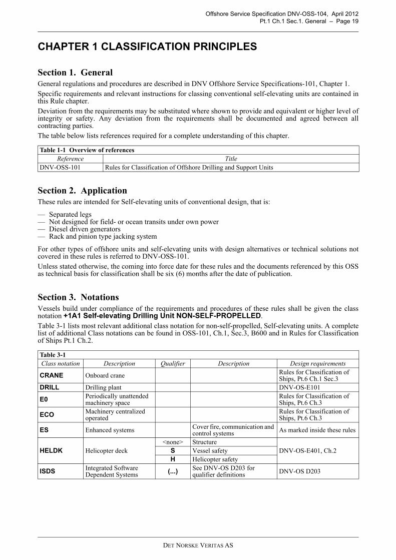
Section 1. GeneralGeneral regulations and procedures are described in DNV Offshore Service Specifications-101, Chapter 1.Specific requirements and relevant instructions for classing conventional self-elevating units are contained inthis Rule chapter.Deviation from the requirements may be substituted where shown to provide and equivalent or higher level ofintegrity or safety. Any deviation from the requirements shall be documented and agreed between allcontracting parties.The table below lists references required for a complete understanding of this chapter.
Section 2. ApplicationThese rules are intended for Self-elevating units of conventional design, that is:
— Separated legs— Not designed for field- or ocean transits under own power— Diesel driven generators— Rack and pinion type jacking system
For other types of offshore units and self-elevating units with design alternatives or technical solutions notcovered in these rules is referred to DNV-OSS-101.Unless stated otherwise, the coming into force date for these rules and the documents referenced by this OSSas technical basis for classification shall be six (6) months after the date of publication.
Section 3. NotationsVessels build under compliance of the requirements and procedures of these rules shall be given the classnotation +1A1 Self-elevating Drilling Unit NON-SELF-PROPELLED.Table 3-1 lists most relevant additional class notation for non-self-propelled, Self-elevating units. A completelist of additional Class notations can be found in OSS-101, Ch.1, Sec.3, B600 and in Rules for Classificationof Ships Pt.1 Ch.2.
Table 1-1 Overview of referencesReference Title
DNV-OSS-101 Rules for Classification of Offshore Drilling and Support Units
Table 3-1 Class notation Description Qualifier Description Design requirements
CRANE Onboard crane Rules for Classification of Ships, Pt.6 Ch.1 Sec.3
DRILL Drilling plant DNV-OS-E101
E0 Periodically unattended machinery space
Rules for Classification of Ships, Pt.6 Ch.3
ECO Machinery centralized operated
Rules for Classification of Ships, Pt.6 Ch.3
ES Enhanced systems Cover fire, communication and control systems As marked inside these rules
HELDK Helicopter deck <none> Structure
DNV-OS-E401, Ch.2S Vessel safety H Helicopter safety
ISDS Integrated Software Dependent Systems (...) See DNV-OS D203 for
qualifier definitions DNV-OS D203
DET NORSKE VERITAS AS

Offshore Service Specification DNV-OSS-104, April 2012Pt.1 Ch.1 Sec.3. Notations – Page 20
Recyclable Inventory of Hazardous Materials Part 1
Rules for Classification of Ships, Pt.6 Ch.27
WELL Well intervention system 1 Vessel mounted system
excluding subsea equipment. DNV-OS-E101
2 Vessel mounted system including subsea equipment.
WELLTEST Well test system DNV-OS-E101, Ch.3
Table 3-1 (Continued)Class notation Description Qualifier Description Design requirements
DET NORSKE VERITAS AS

Offshore Service Specification DNV-OSS-104, April 2012Pt.1 Ch.2 Sec.1. Plan Approval – Page 21
CHAPTER 2 PROCEDURES
Section 1. Plan Approval
1.1 FormatThe documentation for plan approval may be submitted on paper or as an electronic file. Any documentssubmitted for re-approval or re-examination shall be especially marked to identify the revised parts. Symbolsused shall be explained, or reference to a standard code shall be given. Each drawing shall include a title fieldstating:
— name of vessel (when known)— name of document issuing company— name and signature of originator and verifier— document no.— document title— revision no.— issue date— scale— set of measurement units used in the document, e.g. System International.
The document title should not include the name of the vessel. The document title should include the functionor component covered by the document. Unique revision numbers shall be allocated to all issues of a document, including the first issue. For documentswith multiple sheets, the revision number should be the same for all sheets.
1.2 SubcontractorsWhere subcontractors and suppliers are involved, the customer shall co-ordinate the submission of requiredplans and documents, as well as co-ordinate any approval comments given by the Society. This does not applyfor materials, components and systems requiring certification as is discussed in more detail in Part 5.
1.3 Plans and data to be submittedGeneral list of plans and data to be submitted are included in the applicable technical chapters of Parts 2 to 4.A detailed and project specific list shall be supplied by the DNV responsible directly after the class agreementhas been signed. Project specific implies that only those documentation is required as is relevant for the designand within the scope of the contractual agreement between yard and DNV.
Section 2. CertificationThe scope of classification requires that specified materials, components and systems intended for the vesselare certified according to the rules. The objective of certification shall ensure that materials, components andsystems used in vessels to be classed by the Society comply with the rule requirements. Certification normally includes both plan approval and survey during production and/or of the final product.A detailed description of the certification process and the specific requirements and lists of the specifiedmaterials, components and systems is given in Part 5.
Section 3. Testing and SurveysDuring the building period DNV carries out surveys at the building yard and its suppliers. The purpose of theseis to verify that the construction, components and equipment satisfy the rule requirements and are in accordancewith the approved plans, that required materials are used, and that functional tests are carried out as prescribedby the rules. A complete description of these test and surveys is given in Part 6.
DET NORSKE VERITAS AS

Offshore Service Specification DNV-OSS-104, April 2012Pt.1 Ch.3 Sec.1. General – Page 22
CHAPTER 3 PRINCIPLES AND CONDITIONS
Section 1. GeneralThe table below lists references required for a complete understanding of this chapter.
Section 2. Principles
2.1 Classification scopeThese rules with the referred standards give requirements in the following areas:
1) Hull and main structure
— strength— materials and welding— corrosion protection— passive fire protection— weathertight and watertight integrity— stability and floatability.
2) Marine and machinery installations and equipmentMachinery installations and equipment, including their related auxiliary systems, to the following mainfunctions:
— jacking gear— fire extinguishing— drainage and bilge pumping— ballasting— emergency shutdown systems.
3) Systems and equipment provided to prevent, detect/ warn of an accidental event and/or prevent or mitigateits effects
4) Secure integrity of shelter areas and usability of escape ways and means of evacuation
2.2 Safety and important systemsTo further frame the content of the rules, the above listed areas and systems are split into safety – (or essential)and important systems.Safety systems are systems needed to be continuous available or available on demand to prevent, to detect, tocontrol or to mitigate the effects of an undesirable event, and to safeguard the personnel, environment and theinstallation. Examples of safety systems covered by main class:
— fire pumps— emergency shut down (ESD) system— fire and gas detection and alarm system — systems required to be supplied from batteries or emergency generator, e.g. public address, emergency
lighting — electric generators and associated power sources supplying the above equipment. — control, monitoring and safety devices or systems for safety systems.
Important services ensure reliable operation and maintain the units operation within operational limitations.Examples of equipment or systems for important services covered by main class:
— fuel oil transfer pumps and fuel oil treatment equipment— seawater pumps (note)— starting air and control air compressors— bilge- and ballast/preload pumps — ventilating fans for engine rooms— ventilating fans for gas dangerous spaces
Table 1-1 Overview of referencesReference Title
DNV-OS-D101 Marine and Machinery Systems and EquipmentDNV-OS-D201 Electrical InstallationsDNV-OS-D202 Automation, Safety, and Telecommunication Systems
DET NORSKE VERITAS AS

Offshore Service Specification DNV-OSS-104, April 2012Pt.1 Ch.3 Sec.3. Environmental Conditions – Page 23
— main lighting system— watertight closing appliances— jacking system— bilge alarm system— electric generators and associated power sources supplying the above equipment. — control, monitoring and safety devices or systems for the above equipment— Seawater pumps (if used as part of a fire water supply system).
2.3 RedundancySafety systems are always to be available. To secure that safety systems always are available, the generalprinciple is that components and systems shall be arranged with redundancy so that a single failure of any activecomponent or system does not cause loss of any main function. Availability is as such, further indirect definedin the requirement to a system i.e where this general principle may be waived and/ or where duplication ofcomponents is required.
Redundancy can either be arranged by installing more than one unit (component redundancy) or by having twoor more systems capable of performing the same functions (system redundancy).
For redundancy on a component level a single failure of an active component shall not lead to a reduction ofthe output power for the main function served.
When two or more components are performing the same function, these shall be mutually independent and atleast one shall be independently driven. Components arranged as part of the designed redundancy, yet onlyperforming important functions to a main unit, can be directly powered by the main unit through separate powertransmissions, on the condition that these components are not necessary for the starting of the main unit.
When traditional mechanical components are replaced by electronic components, these components shall havethe same reliability as the mechanical component being replaced.
Machinery or equipment having remote or automatic control, shall have additional alternative provisions forattendance and operation.
2.4 Failure effectsIn the event of failure, components and systems shall enter the least hazardous of the possible failure states withregard to machinery, personnel and environment.
Failure of one component in a system arranged as part of the designed redundancy shall not lead to failure ordamage to backup or parallel components or systems.
For failure detection see Pt.4, Ch.4, Sec.2.1.
Section 3. Environmental ConditionsAll components and systems covered by this standard shall be designed to operate under the followingenvironmental conditions unless otherwise specified in the detailed requirements for the component or system.
3.1 Design temperatureThe unit’s design temperature is a minimum temperature used as a criterion for the selection of steel grades.The design temperature shall be specified by the customer and is to be taken as the lower or equal to the lowestmean daily temperature in air for the relevant areas. For seasonal restricted operations the lowest mean dailytemperature in air for the season may be applied.
Guidance note:It is underlined that design temperatures below 0 degrees are only relevant for waters in the higher latitudes (e.g.northern part of North Sea, Canadian waters etc). For these waters and their harsh conditions, relevant considerationsshould be taken (e.g. OS-C201, Sec.2 B304 on water trapped in local structures, OS-D101, Ch.2 Sec.3 F108 onfreezing of vents, OS-D301 in protecting the fire equipment against freezing etc) In addition, class notations relatedto cold climate operations as listed in OSS-101, Ch.1 Sec.3, B 700 can be relevant as well.
---e-n-d---of---G-u-i-d-a-n-c-e---n-o-t-e---
The design temperature shall be listed in the appendix to Class Certificate (see also Pt.6, Ch.5, Sec.3). Guidance note:In the different offshore standards is in addition to a design temperature a service temperature defined. For self-elevating units, the two temperatures are equal.
---e-n-d---of---G-u-i-d-a-n-c-e---n-o-t-e---
3.2 Temperature for machinery systems and equipmentMachinery systems and equipment shall be constructed for continuous operation in the range of ambient
DET NORSKE VERITAS AS
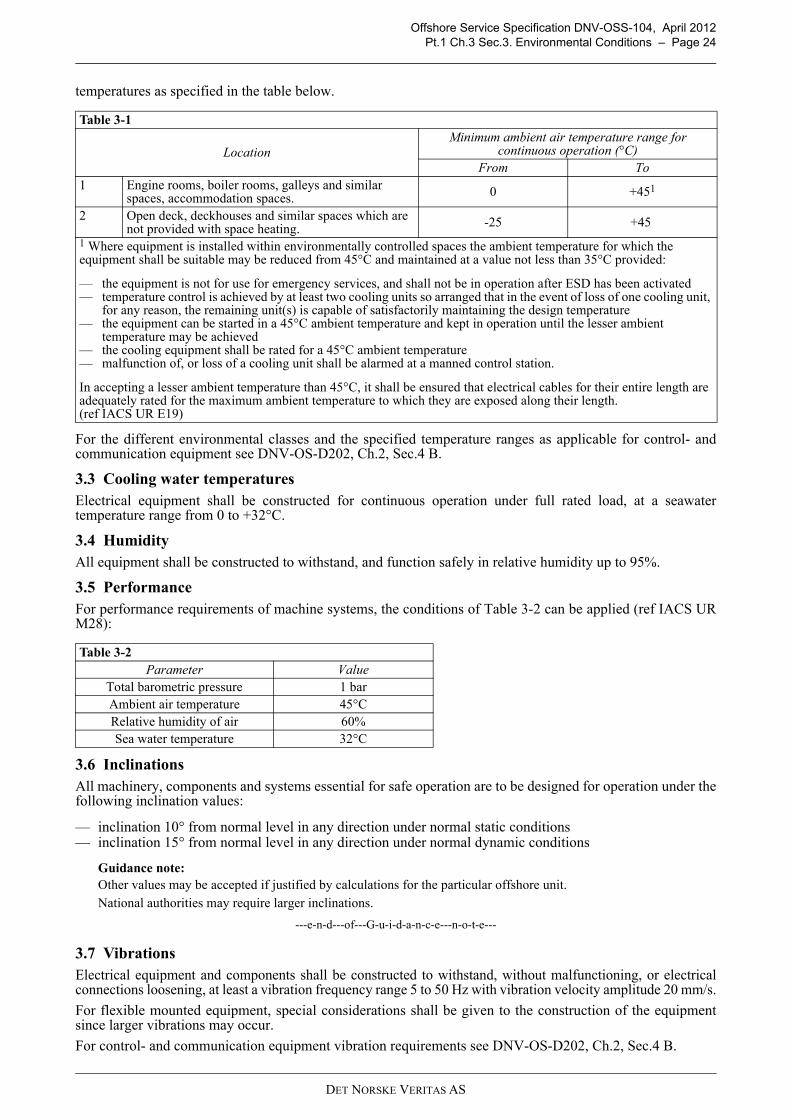
Offshore Service Specification DNV-OSS-104, April 2012Pt.1 Ch.3 Sec.3. Environmental Conditions – Page 24
temperatures as specified in the table below.
For the different environmental classes and the specified temperature ranges as applicable for control- andcommunication equipment see DNV-OS-D202, Ch.2, Sec.4 B.
3.3 Cooling water temperaturesElectrical equipment shall be constructed for continuous operation under full rated load, at a seawatertemperature range from 0 to +32°C.
3.4 HumidityAll equipment shall be constructed to withstand, and function safely in relative humidity up to 95%.
3.5 Performance For performance requirements of machine systems, the conditions of Table 3-2 can be applied (ref IACS URM28):
3.6 InclinationsAll machinery, components and systems essential for safe operation are to be designed for operation under thefollowing inclination values:
— inclination 10° from normal level in any direction under normal static conditions— inclination 15° from normal level in any direction under normal dynamic conditions
Guidance note:Other values may be accepted if justified by calculations for the particular offshore unit.National authorities may require larger inclinations.
---e-n-d---of---G-u-i-d-a-n-c-e---n-o-t-e---
3.7 Vibrations Electrical equipment and components shall be constructed to withstand, without malfunctioning, or electricalconnections loosening, at least a vibration frequency range 5 to 50 Hz with vibration velocity amplitude 20 mm/s.
For flexible mounted equipment, special considerations shall be given to the construction of the equipmentsince larger vibrations may occur.
For control- and communication equipment vibration requirements see DNV-OS-D202, Ch.2, Sec.4 B.
Table 3-1
Location Minimum ambient air temperature range for
continuous operation (°C) From To
1 Engine rooms, boiler rooms, galleys and similar spaces, accommodation spaces. 0 +451
2 Open deck, deckhouses and similar spaces which are not provided with space heating. -25 +45
1 Where equipment is installed within environmentally controlled spaces the ambient temperature for which the equipment shall be suitable may be reduced from 45°C and maintained at a value not less than 35°C provided:
— the equipment is not for use for emergency services, and shall not be in operation after ESD has been activated— temperature control is achieved by at least two cooling units so arranged that in the event of loss of one cooling unit,
for any reason, the remaining unit(s) is capable of satisfactorily maintaining the design temperature— the equipment can be started in a 45°C ambient temperature and kept in operation until the lesser ambient
temperature may be achieved— the cooling equipment shall be rated for a 45°C ambient temperature— malfunction of, or loss of a cooling unit shall be alarmed at a manned control station.
In accepting a lesser ambient temperature than 45°C, it shall be ensured that electrical cables for their entire length are adequately rated for the maximum ambient temperature to which they are exposed along their length.(ref IACS UR E19)
Table 3-2 Parameter Value
Total barometric pressure 1 barAmbient air temperature 45°CRelative humidity of air 60%Sea water temperature 32°C
DET NORSKE VERITAS AS
Offshore Service Specification DNV-OSS-104, April 2012Page 25
PART 2 – MATERIALS AND WELDING
DET NORSKE VERITAS AS

Offshore Service Specification DNV-OSS-104, April 2012Pt.2 Ch.1 Sec.1. General – Page 26
CHAPTER 1 METALLIC MATERIALS
Section 1. GeneralThe table below lists references required for a complete understanding of this chapter.
Section 2. Principles Principles for certification of steels for structural application are given by standard DNV-OS-B101.Requirements for the specific materials selections are given in the technical chapters of Part 3 and 4 of thisbook:
When material other than steel and aluminum alloys (evidenced by previous service experience) is used instructural fabrication and for equipment relating to Main Class, documentation of the material’s applicabilityfor intended purpose shall be documented with due regard to the material’s mechanical properties and itsresponding service performances. Materials with low heat resistance shall not be used in components where fire may cause outflow of flammableor toxic fluids, flooding of any watertight compartment or destruction of watertight integrity.
Guidance note:Materials with high heat resistance are materials having a melting point greater than 925°C. Materials with low heatresistance are all other materials. Deviations from the above requirement will be subject to special considerations.
---e-n-d---of---G-u-i-d-a-n-c-e---n-o-t-e---
Table 1-1 Overview of referencesReference Title
DNV-OS-C101 Design of Offshore Steel Structures, General DNV-OS-C201 Structural Design of Offshore Units (WSD method) DNV-OS-C301 Stability and Watertight IntegrityDNV-OS-D101 Marine and Machinery Systems and EquipmentDNV-OS-E301 Position Mooring
Table 2-1 Topic Rule book reference Offshore standard
Structural steel Pt.3, Ch.1, Sec.6.2 C201, Ch.2, Sec.4 D C201, Ch.2, Sec.12, B300
Watertight Integrity, Freeboard and Weathertight Closing Appliances
C301, Ch.2, Sec.2 B
Towline fastening devices and their supporting structures
Pt.3, Ch.3, Sec.2.2 C101, Ch.1 Sec.4
Anchors E301, Ch.2 Sec.4 BWindlasses, winches and chain stoppers E301, Ch.2, Sec.2, K400Materials for piping Pt.4, Ch.1, Sec.4.1 D101, Ch.2, Sec.2 BJacking gear Pt.4, Ch.1, Sec.6.3
DET NORSKE VERITAS AS

Offshore Service Specification DNV-OSS-104, April 2012Pt.2 Ch.2 Sec.1. General – Page 27
CHAPTER 2 STRUCTURAL FABRICATION
Section 1. GeneralPrinciples and requirements for structural fabrication are given by standard DNV-OS-C401 as discussed indetail in Pt.6, Ch.3
DET NORSKE VERITAS AS
Offshore Service Specification DNV-OSS-104, April 2012Page 28
PART 3 – HULL AND EQUIPMENT
DET NORSKE VERITAS AS
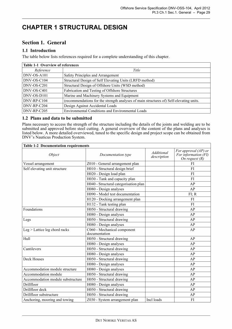
Offshore Service Specification DNV-OSS-104, April 2012Pt.3 Ch.1 Sec.1. General – Page 29
CHAPTER 1 STRUCTURAL DESIGN
Section 1. General
1.1 IntroductionThe table below lists references required for a complete understanding of this chapter.
1.2 Plans and data to be submittedPlans necessary to access the strength of the structure including the details of the joints and welding are to besubmitted and approved before steel cutting. A general overview of the content of the plans and analyses islisted below. A more detailed overviewed, tuned to the specific design and project scope can be obtained fromDNV’s Nauticus Production System.
Table 1-1 Overview of referencesReference Title
DNV-OS-A101 Safety Principles and ArrangementDNV-OS-C104 Structural Design of Self Elevating Units (LRFD method)DNV-OS-C201 Structural Design of Offshore Units (WSD method) DNV-OS-C401 Fabrication and Testing of Offshore StructuresDNV-OS-D101 Marine and Machinery Systems and EquipmentDNV-RP-C104 (recommendations for the strength analyses of main structures of) Self-elevating units.DNV-RP-C204 Design Against Accidental LoadsDNV-RP-C205 Environmental Conditions and Environmental Loads
Table 1-2 Documentation requirements
Object Documentation type Additional description
For approval (AP) or For information (FI)
On request (R) Vessel arrangement Z010 - General arrangement plan FISelf elevating unit structure H010 - Structural design brief FI
H020 - Design load plan FI H030 - Tank and capacity plan FI H040 - Structural categorisation plan AP H080 - Design analyses AP H090 - Model test documentation FI; R H120 - Docking arrangement plan FI H132 - Tank testing plan FI
Foundations H050 - Structural drawing APH080 - Design analyses AP
Legs H050 - Structural drawing APH080 - Design analyses AP
Leg > Lattice leg chord racks C060 - Mechanical component documentation
AP
Hull H050 - Structural drawing APH080 - Design analyses AP
Cantilevers H050 - Structural drawing APH080 - Design analyses AP
Deck Houses H050 - Structural drawing APH080 - Design analyses AP
Accommodation module structure H080 - Design analyses APAccommodation module H050 - Structural drawing APAccommodation module substructure H050 - Structural drawing APDrillfloor H080 - Design analyses APDrillfloor deck H050 - Structural drawing APDrillfloor substructure H050 - Structural drawing APAnchoring, mooring and towing Z030 - System arrangement plan Incl loads FI
DET NORSKE VERITAS AS

Offshore Service Specification DNV-OSS-104, April 2012Pt.3 Ch.1 Sec.2. Principles – Page 30
Section 2. PrinciplesThe unit or installation shall be designed and constructed with sufficient integrity to withstand operational andenvironmental loading throughout its lifecycle.
Systems and structures shall be designed with suitable functionality and survivability for prevention of, orprotection from, design accident events affecting the unit or installation. Refer also DNV-RP-C204 - DesignAgainst Accidental Loads. The structure shall be designed to resist relevant loads associated with conditions that may occur during allstages of the life-cycle of the unit. The conditions that should be considered are:
— transit condition(s)— installation condition— operating condition(s)— survival condition— retrieval condition.
Section 3. Analysis and CalculationsStructural analysis shall be performed to evaluate the structural strength due to global and local effects as
Anchoring arrangement H100 - Equipment number calculation
AP
Z090 - Equipment list Including type of anchor, grade of anchor chain, and type and breaking load of steel and fibre ropes.
AP
Jack houses Jack house > Fixation system supportHelicopter deck supporting structureAccommodation module supporting structureDrillfloor supporting structureDerrick supporting structureDrilling fluid return trip independent tanks supporting structureMain electric power generation arrangement (Main/Emergency) > Main generator supporting structure (Main/Emergency)Auxiliary boiler supporting structureAuxiliary feed water independent tanks supporting structureHelicopter fuel storage independent tanks supporting structuresSea chestsBallast pumping unit arrangement (Service) > Ballast pumping unit supporting structure (Service)Internal watertight door / ramp supporting structureAccommodation ladder supporting structureAnchor winch supporting structureAnchor chain stopper supporting structureAnchor fairlead supporting structurePassive towing equipment supporting structuresOffshore crane pedestalA-frames supporting structuresOffshore crane supporting structure
H050 - Structural drawing1 1 Including footprint. Applicable if static force > 50 kN or bending moment > 100 kNm.
AP
H080 - Design analyses2 2 Applicable if static force > 50 kN or bending moment > 100 kNm
AP
DET NORSKE VERITAS AS
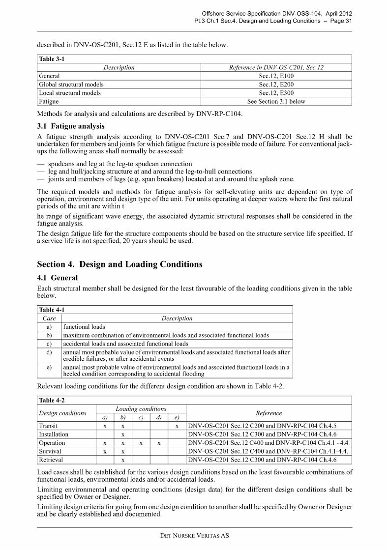
Offshore Service Specification DNV-OSS-104, April 2012Pt.3 Ch.1 Sec.4. Design and Loading Conditions – Page 31
described in DNV-OS-C201, Sec.12 E as listed in the table below.
Methods for analysis and calculations are described by DNV-RP-C104.
3.1 Fatigue analysisA fatigue strength analysis according to DNV-OS-C201 Sec.7 and DNV-OS-C201 Sec.12 H shall beundertaken for members and joints for which fatigue fracture is possible mode of failure. For conventional jack-ups the following areas shall normally be assessed:
— spudcans and leg at the leg-to spudcan connection— leg and hull/jacking structure at and around the leg-to-hull connections — joints and members of legs (e.g. span breakers) located at and around the splash zone.
The required models and methods for fatigue analysis for self-elevating units are dependent on type ofoperation, environment and design type of the unit. For units operating at deeper waters where the first naturalperiods of the unit are within t
he range of significant wave energy, the associated dynamic structural responses shall be considered in thefatigue analysis.
The design fatigue life for the structure components should be based on the structure service life specified. Ifa service life is not specified, 20 years should be used.
Section 4. Design and Loading Conditions
4.1 GeneralEach structural member shall be designed for the least favourable of the loading conditions given in the tablebelow.
Relevant loading conditions for the different design condition are shown in Table 4-2.
Load cases shall be established for the various design conditions based on the least favourable combinations offunctional loads, environmental loads and/or accidental loads.
Limiting environmental and operating conditions (design data) for the different design conditions shall bespecified by Owner or Designer.
Limiting design criteria for going from one design condition to another shall be specified by Owner or Designerand be clearly established and documented.
Table 3-1 Description Reference in DNV-OS-C201, Sec.12
General Sec.12, E100Global structural models Sec.12, E200Local structural models Sec.12, E300Fatigue See Section 3.1 below
Table 4-1 Case Description
a) functional loadsb) maximum combination of environmental loads and associated functional loadsc) accidental loads and associated functional loadsd) annual most probable value of environmental loads and associated functional loads after
credible failures, or after accidental eventse) annual most probable value of environmental loads and associated functional loads in a
heeled condition corresponding to accidental flooding
Table 4-2
Design conditions Loading conditions
Referencea) b) c) d) e)
Transit x x x DNV-OS-C201 Sec.12 C200 and DNV-RP-C104 Ch.4.5Installation x DNV-OS-C201 Sec.12 C300 and DNV-RP-C104 Ch.4.6Operation x x x x DNV-OS-C201 Sec.12 C400 and DNV-RP-C104 Ch.4.1 - 4.4 Survival x x DNV-OS-C201 Sec.12 C400 and DNV-RP-C104 Ch.4.1-4.4. Retrieval x DNV-OS-C201 Sec.12 C300 and DNV-RP-C104 Ch.4.6
DET NORSKE VERITAS AS

Offshore Service Specification DNV-OSS-104, April 2012Pt.3 Ch.1 Sec.5. Loads and Load Effects – Page 32
If the unit is intended to be dry docked, the footing structure (i.e. spudcans) and/or the barge shall be suitablystrengthened to withstand the loads.
4.2 Environmental conditions Environmental conditions for design of self-elevating units are given by DNV-OS-C201 Sec.12 D.
Combination of loads are given in DNV-OS-C201 Sec.3 F and DNV-OS-C201 Sec.12 F1200.
In conjunction with combination of environmental loads for loading condition b) (ref. DNV-OS-C201 Sec.3F104) the sustained wind velocity, i.e. the 1 minute average velocity, shall be used. If gust wind alone is moreunfavourable than sustained wind in conjunction with wave forces, the gust wind velocity shall be used. Forlocal load calculations gust wind velocity shall be used.
Principles and formulas for calculation of wind loads may be taken from DNV-RP-C205 Sec.2.Guidance note:For units intended for unrestricted service (worldwide operation) a wind velocity of not less than 51.5 m/s (v1min10)combined with maximum wave forces will cover most locations. The corresponding wind force should be based on awind velocity profile given by DNV-RP-C205 Chapter 2. Clause 2.3.2.12, or equivalent. See also the guidance givenin DNV-RP-C104 Sec.2.4.
---e-n-d---of---G-u-i-d-a-n-c-e---n-o-t-e---
4.3 Accidental conditions The overall objective for design with respect to accidental conditions is that unit's main safety functions shallnot be impaired by accidental events. Satisfactory protection against accidental damage may be achieved bytwo barriers:
— reduction of damage probability — reduction of damage consequences.
The design against accidental loads may be done by direct calculation of the effects imposed by the loads onthe structure, or indirectly, by design of the structure as tolerable to accidents. Examples of the latter arecompartmentation of floating units which provides sufficient integrity to survive certain collision scenarioswithout further calculations.
Guidance note:Recommendations for design of structures exposed to accidental events can be found in DNV-RP-C204.
---e-n-d---of---G-u-i-d-a-n-c-e---n-o-t-e---
General requirements for accidental events are given by DNV-OS-C201 as listed in Table 4-3.
Technical requirements given in DNV-OS-C201 related to design for earthquake of mobile self-elevatingdrilling units are not mandatory as part of classification.
For the loads taken into account for accidental conditions see Section 5.1
Section 5. Loads and Load EffectsLoads and load effects are given by DNV-OC-C201 as listed in the table below.
Table 4-3 Description Reference in DNV-OS-C201
Collisions Sec.12, I200Dropped objects Sec.8, B300Explosions Sec.8, B500Unintended flooding Sec.12, I600
Table 5-1 Description Reference in DNV-OS-C201
Permanent functional loads Sec.3 C and Sec.12 F200Variable function loads Sec.3 D and Sec.12 F300Tank loads Sec.3 D300 and Sec.12 F400Environmental loads Sec.3 E, and Sec.12 F500 – F1100 Accidental loads Sec.3 G Deformation loads Sec.3 HFatigue loads Sec.7 and Sec.12 H
DET NORSKE VERITAS AS

Offshore Service Specification DNV-OSS-104, April 2012Pt.3 Ch.1 Sec.6. Structural Categorization, Material and Inspection Principles – Page 33
5.1 Accidental loads
Accidental loads are to be taken into consideration. The loads shall be based on an individual frequency ofoccurrence in the order of 10-4 per year, corresponding to an overall frequency of 4 x 10⁻⁴ per year as theimpairment frequency limit. The generic accidental loads are given by DNV-OS-A101,-C201 and -C301 asdetailed in Table 5-2.
5.2 Load calculations
Load calculations are described in DNV-OS-C201 Sec.12 E. and DNV-RP-C104.
Section 6. Structural Categorization, Material and Inspection Principles
6.1 Structural categorization
Application categories for structural components are defined in DNV-OS-C201 Sec.4. Structural members ofself-elevating units with separate footing are normally found in the following groups:
a) Special category
— Highly stressed elements of bottom of leg, including leg connection to spudcan.— Intersections of lattice type- or trussed leg structure, which incorporates novel construction, including
the use of steel castings.— Highly stressed elements of guide structures, jacking and locking system(s), jackhouse and support
structure.— Highly stressed elements of crane pedestals, etc. and their supporting structure.
Guidance note:Highly stressed areas are normally considered to be areas utilized more than 85% of the allowable yield capacity.
---e-n-d---of---G-u-i-d-a-n-c-e---n-o-t-e---
b) Primary category
— Combination of bulkhead, deck, side and bottom plating within the hull which forms “Box” or “I” typeacting as main beam
— All components of lattice type legs and external plating of cylindrical legs.— Jackhouse supporting structure and bottom footing structure, which receives initial transfer of load
from legs.— Internal bulkheads, shell and deck of spudcan which are designed to distribute major loads, either
uniform or concentrate.— Main support structure of heavy substructures and equipment, e.g. cranes, drill floor substructure, life
boat platform and helicopter deck.
c) Secondary category
— Deck, side and bottom plating of hull except areas where the structure is considered primary or specialapplication.
— Bulkheads, stiffeners, decks and girders in hull that are not considered as primary or special application.— Internal bulkheads and girders in non-trussed legs.— Internal bulkheads, stiffeners and girders of spudcan structures, except where the structures are
considered primary or special application.
6.2 Material selection
General requirement to material selection are given by DNV-OS-C201 Sec.4 D
For rack plates with specified minimum yield stress equal to 690 N/mm2 in rack and pinion jacking systemssteel grade NV E690 is acceptable for rack plates with thickness up to 250 mm and for service temperaturedown to -20°C.
Table 5-2 Description Reference in DNV-OS-A101, -C201 and -C301
Dropped objects DNV-OS-A101 Sec.2 D200 and DNV-OS-C201 Sec.8 B300Collision loads DNV-OS-A101 Sec.2 D300 and DNV-OS-C201 Sec.8 B200 1)Unintended flooding DNV-OS-C301 Ch.2 Sec.1 E100/E300Explosions loads DNV-OS-A101 Sec.2 D600 and DNV-OS-C201 Sec.8 B500
DET NORSKE VERITAS AS

Offshore Service Specification DNV-OSS-104, April 2012Pt.3 Ch.1 Sec.7. Structural Strength – Page 34
Section 7. Structural StrengthGeneral requirements are given by DNV-OS-C201 Sec.5 with specific considerations for Self-Elevating unitsin Sec.12 G as listed in the table below.
7.1 Footing strengthSpud cans shall be designed by taking into account the effect of uneven distribution from seabed conditionsand scouring.
The strength checks for the spudcan, the leg-to-spudcan connections and the two lowest leg bays (lattice legs)for separate type spudcans should normally not be based on lower loads than given below:
i) The design load Fv is evenly distributed over 50% of the bottom area:and,
qd = design contact pressure Med = design eccentricity moment Fvd = maximum design axial load in the leg accounting for functional loads and environmental
overturning loads.R = equivalent radius of spudcan contact area
ii) The design load Fvd is concentrically distributed over a range of bearing areas, from the minimum designpenetration (supported on spudcan tip) up to and including full spudcan bottom area.
iii) If elevated condition is designed based on pinned leg footings; The spudcan and the leg-to-spudcanconnections are to be designed for the maximum vertical reaction and the associated horizontal reaction inconjunction with 35% of the maximum calculated moment at the lower guide (to account for the eccentriceffects of possible scour and uneven bottom conditions) acting in the most unfavourable direction. Themaximum lower guide bending moment is to be calculated with pin-ended conditions.
iv) If elevated condition is designed based on moment fixity at leg footings:
— The maximum vertical reaction, in conjunction with the associated horizontal reaction and spudcan-soilfixity moment, acting in the most unfavourable direction.
— The maximum spudcan-soil fixity moment in conjunction with the associated vertical and horizontalreactions, acting in the most unfavourable direction.
The design moments and soil pressures above are based on a relative homogenous seabed, for example for sandor clay seabed. Local stiff soil supporting in the bottom plate outside the strong tip should be avoided. It isassumed that this will be evaluated in the sea bed surveys in connection with site specific assessments whenthe unit is used on specific locations.
Guidance note:Cases (i) and (ii) above shall always to be checked together with one of the cases (iii) or (iv).
Case (iii) or (iv) is checked based on the leg footing assumption used in design.
For quadratic shaped spudcans: For rectangular spudcans with long side b and Short side s, the design load Fv can beevenly distributed over 50% of the bottom area. The corresponding design pressure
Table 7-1 Description Reference in DNV-OS-C201
Flat Plated Structures and Stiffened Panels Ch.2, Sec.5 BShell Structures Ch.2, Sec.5 CTubular Members, Tubular Joints and Conical Transitions Ch.2, Sec.5 DNon-Tubular Beams, Columns and Frames Ch.2, Sec.5 EStrength of Plating and Stiffeners Ch.2, Sec.6 BBending and Shear in Girders Ch.2, Sec.6 CGlobal capacity Ch.2, Sec.12, G200Leg strength Ch.2, Sec.12, G400Jackhouse support strength Ch.2, Sec.12, G500Hull strength Ch.2, Sec.12, G600
RFM ve 425.0=
25.0 R
Fq v
c π=
DET NORSKE VERITAS AS

Offshore Service Specification DNV-OSS-104, April 2012Pt.3 Ch.1 Sec.8. Weld Connections – Page 35
The corresponding design moment about the two main axis:Med-1 = 0,25 Fvd b Med-2 = 0,25 Fvd sFor classification the design values in (i) to (iv) will be included in the “Appendix to Class Certificate” as basis fordesign of the spudcan and lower leg.
---e-n-d---of---G-u-i-d-a-n-c-e---n-o-t-e---
For other types of bottom support, e.g. mats special considerations should be made.
7.2 Section scantlingsThe requirements in this section are applicable for:
— plate thicknesses and local strength of panels— simple girders— calculations of complex girder systems.
Requirements are given in OS-C201 Sec.6 B for Strength of plating and stiffeners and Sec.6 C for Bending andshear in Girders.
7.3 Fatigue strength For units intended to follow normal inspection requirements according to class requirements, i.e. 5 yearlyinspections in dry dock or sheltered waters, a Design Fatigue Factor (DFF) of 1.0 may be applied for accessiblemembers. For not accessible members DFF shall be applied to structural elements according to the principlesin Sec.7 A200.Units intended to operate continuously at the same location for more than 5 years, i.e. without planned dry dockor sheltered water inspection, shall comply with the requirements given in Appendix Requirements for fatiguestrength is given by DNV-OS-C201 Sec.7 A, B, C and Sec.12 H.Relevant fatigue analysis are given in Section 3.1 of this chapter.
Section 8. Weld ConnectionsRequirements for weld connections is given by DNV-OS-C201 Ch.2, Sec.9 as listed in the table below.
Section 9. Corrosion ControlCorrosion control of structural steel for offshore structures comprises:
— coatings and/or cathodic protection — use of a corrosion allowance — inspection/monitoring of corrosion — control of humidity for internal zones (compartments).
Requirements for corrosion control are given by DNV-OS-C201 Ch.2, Sec.10 as listed in Table 9-1. Themanufacturing/installation of systems for corrosion control are covered in DNV-OS-C401 Sec.5.
Table 8-1 Description Reference in DNV-OS-C201 Ch.2
Butt joints Sec.9, B100Tee or cross joints Sec.9, B200Slot welds Sec.9, B300Lap joint Sec.9, B400Weld Size Sec.9, C
Table 9-1 Description Reference in DNV-OS-C201
Techniques for Corrosion Control Related to Environmental Zones
Ch.2, Sec.10 B
Cathodic Protection Ch.2, Sec.10 CCoating Systems Ch.2, Sec.10 D
qdFvd
0.5 b s----------------=
DET NORSKE VERITAS AS

Offshore Service Specification DNV-OSS-104, April 2012Pt.3 Ch.2 Sec.1. General – Page 36
CHAPTER 2 STABILITY AND WATERTIGHT INTEGRITY
Section 1. General
1.1 IntroductionThis section provides principles, technical requirements and guidance related to stability, watertight integrity,freeboard and weathertight closing appliances. The table below lists references required for a completed understanding of this chapter.
1.2 Plans and data to be submittedA general overview of the content of the plans and analyses is listed below. A more detailed overviewed, tunedto the specific design and project scope can be obtained from DNV’s Nauticus Production System.
Table 1-1 Overview of referencesReference Title
IMO MODU Code Code for the construction and equipment of Mobile Offshore Drilling Units, 2009ICLL 1966 International Convention on Load Lines, 1966, amended by Protocol 1988 DNV-OS-B101 Metallic MaterialsDNV-OS-C301 Stability and Watertight IntegrityDNV- Ship Rules Pt.6 Ch.9 Loading Computer Systems (LCS) for Stability and Longitudinal StrengthDNV-OS-D101 Marine and Machinery Systems and Equipment
Table 1-2 Documentation requirements
Object Documentation type Additional description For approval (AP) or For information (FI)
On request (R) Stability B010 - Lines plan and offset tables FI
B020 - External watertight integrity plan
FI
B040 - Stability analysis AP B050 - Preliminary stability manual AP B100 - Inclining test and lightweight survey procedure
AP
B110 - Inclining test or lightweight survey report
AP
B110 - Final stability manual AP Damage stability B030 - Internal watertight integrity plan FI
B070 - Preliminary damage stability calculation
AP
B130 - Final damage stability calculation
AP
External watertight and weathertight integrity
B200 - Freeboard plan AP
Internal watertight door / ramp
Z030 - System arrangement plan Applicable for all watertight doors. Including for each door: Size, design principle (sliding, hinged), pressure rating and fire rating. Including remote control positions.
AP
Internal watertight doors > Door structure
C030 - Detailed drawing AP
Service hatchways C010 - Design criteria FIVentilation System S012 - Ducting diagram AP
DET NORSKE VERITAS AS

Offshore Service Specification DNV-OSS-104, April 2012Pt.3 Ch.2 Sec.2. Stability – Page 37
Section 2. StabilityThis section gives requirements related to the following design parameters:
1) Buoyancy and floatability.
2) Wind exposed portions.
3) Draught range at various modes of service.
4) Watertight and weathertight closing of external openings.
5) Internal watertight integrity and watertight subdivision.
6) Lightweight and loading conditions.
The combination of the design parameters (1-5) will determine the maximum allowable vertical centre ofgravity (VCG) of the unit at the applicable service draughts and modes.
In order to determine VCG of the actual loading conditions, the lightweight and its centre of gravity must beknown. This shall be obtained by an inclining test carried out in accordance with IMO MODU Code, 2009.
Loading computers for stability calculation shall be considered as supplementary to the stability manual or thestability part of the operation manual. If onboard computers for stability calculations are installed, thesesystems shall be approved in accordance with requirements in Rules for Classification of Ships Pt.6 Ch.9
Section 3. Watertight Integrity, Freeboard and Weathertight Closing AppliancesWatertight closing appliances are required for those external openings being submerged at least up to an angleof heel equal to the first intercept in intact or damage condition, whichever is greatest.
Weathertight closing appliances are required for those external openings being submerged at least up to anangle of heel equal to the dynamic angle. This applies to any opening within 4.0 m above the final waterline aswell.
Ducts or piping, which may cause progressive flooding in case of damage, shall generally not be used in thedamage penetration zone.
Location of openings where watertight and weathertight integrity are required, are illustrated in DNV-OS-C301Ch.2, Sec.2 J.
The requirements for operation and locking of doors and hatch covers are given in DNV-OS-C301 Ch.2, Sec.2 J.
For Testing of doors and hatch covers ref DNV-OS-C301 Ch.2, Sec.2 I.
3.1 MaterialsMaterials and material certificates for:
— rolled steel for structural applications and pressure vessels,— steel tubes, pipes and fittings,— steel forgings,— steel castings,— aluminium alloys,
shall comply with the requirements given by DNV-OS-B101 unless otherwise stated in the relevant technicalreference documents.
Stainless steel shall be with a maximum carbon content of 0.05%. The stainless steel material shall be of thewhite pickled and passivated condition. Aluminium shall be of seawater resistant type.
Table 2-1 Description Reference
Determination of Lightweight IMO MODU Code, 2009, Regulation 3.1Determination of wind forces: IMO MODU Code, 2009, Regulation 3.2Intact Stability Requirements: IMO MODU Code, 2009, Regulation 3.3Damage Stability Requirements: IMO MODU Code, 2009, Regulation 3.4 1), 2) 1) The internal subdivision shall be adequate to enable the unit or installation to comply with the damage stability requirements
2) The following permeability factors shall be assumed in the calculations:
— Store rooms: 0.60— Engine room: 0.85— Tanks, void spaces etc: 0.95
Other permeabilities may be accepted if documented by calculations.
DET NORSKE VERITAS AS

Offshore Service Specification DNV-OSS-104, April 2012Pt.3 Ch.2 Sec.3. Watertight Integrity, Freeboard and Weathertight Closing Appliances – Page 38
3.2 Watertight integrityThe number of openings in watertight subdivisions shall be kept to a minimum compatible with the design andproper working of the unit or installation. Where penetrations of watertight decks and bulkheads are necessaryfor access, piping, ventilation, electrical cables etc., arrangements shall be made to maintain the watertightintegrity of the enclosed compartments.
Piping and electrical systems for operation of watertight closing appliances shall be in accordance with relevantrequirements given in DNV-OS-D101 unless otherwise specified in this section.
The strength and arrangement of sliding doors and hatch covers and their frames as well as the capacity of theclosing systems shall be sufficient to ensure efficient closing of doors and hatch covers when water with a headof 2.0 m is flowing through the opening, and at an inclination of 17° in any direction.
In addition watertight integrity shall comply with the details OS-C301, Ch.2, Sec.2 as given in the table below.
3.3 Weathertight closing appliances The closing appliances shall in general have a strength at least corresponding to the required strength of thepart of the hull in which they are fitted. For side scuttles and windows, however, the pressure head shall not betaken less than 2.5 m water column.
Guidance note:Some requirements are also governed by the regulations in the «International Convention of Load Lines 1966»:- doors in reg.12- definition of positions in reg.13- hatchways in reg.14 to reg.16- machinery space openings in reg.17- miscellaneous openings in reg.18- ventilators in reg.19- air pipes in reg.20- scuppers, inlets and discharges in reg.22- side scuttles in reg.23- freeing ports in reg.24- special requirements in reg.25 to reg.27.
---e-n-d---of---G-u-i-d-a-n-c-e---n-o-t-e---
Requirements for specific closing appliances is given in OS-C301, Ch.2, Sec.1 and 2 as listed in the table below.
3.4 FreeboardLoad lines for self-elevating units are calculated under the terms of the ILLC 1966. When floating or when intransit from one operational area to another, the units shall be subject to all the conditions of assignment of theILLC 1966 unless specifically accepted. The regulations of relevant national authorities shall also be observed.
Draught marks shall be located in positions, which will ensure accurate determination of draughts, trim andheel and where they are clearly visible to personnel operating the unit or installation. The reference line shallbe defined in the stability manual.
Table 3-1 Description Reference in DNV-OS-C301, Ch.2
Internal openings Sec.2, C200External Opening Sec.2, C300Strength of watertight doors and hatch covers Sec.2, C400Frame and bulkhead interface Sec.2, C500Operation and control of watertight doors and hatch covers Sec.2, C600
Table 3-2 Description Reference in DNV-OS-C301, Ch.2
Chain Lockers Ch.2, Sec.1 E800Weathertight doors Ch.2, Sec.2 D200Weathertight hatch coamings and covers Ch.2, Sec.2 D300Gaskets and closing devices Ch.2, Sec.2 D400Drainage arrangement Ch.2, Sec.2 D500Buckling check Ch.2, Sec.2 D600
DET NORSKE VERITAS AS
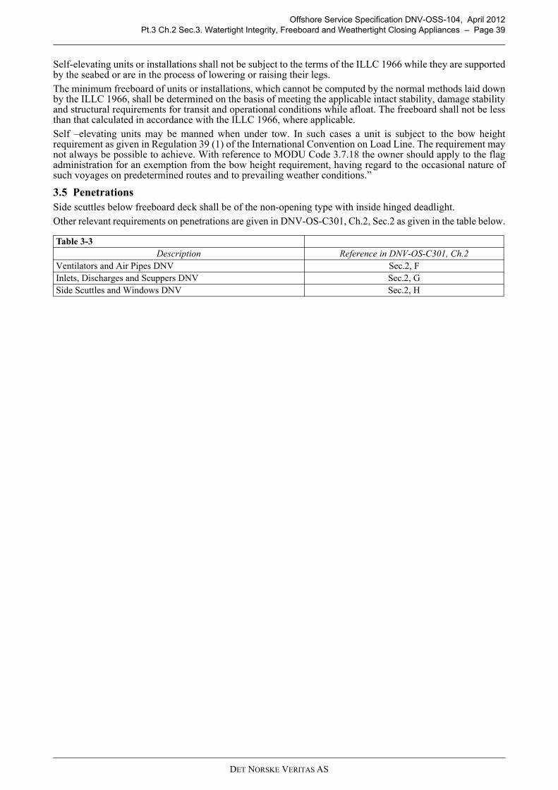
Offshore Service Specification DNV-OSS-104, April 2012Pt.3 Ch.2 Sec.3. Watertight Integrity, Freeboard and Weathertight Closing Appliances – Page 39
Self-elevating units or installations shall not be subject to the terms of the ILLC 1966 while they are supportedby the seabed or are in the process of lowering or raising their legs. The minimum freeboard of units or installations, which cannot be computed by the normal methods laid downby the ILLC 1966, shall be determined on the basis of meeting the applicable intact stability, damage stabilityand structural requirements for transit and operational conditions while afloat. The freeboard shall not be lessthan that calculated in accordance with the ILLC 1966, where applicable.Self –elevating units may be manned when under tow. In such cases a unit is subject to the bow heightrequirement as given in Regulation 39 (1) of the International Convention on Load Line. The requirement maynot always be possible to achieve. With reference to MODU Code 3.7.18 the owner should apply to the flagadministration for an exemption from the bow height requirement, having regard to the occasional nature ofsuch voyages on predetermined routes and to prevailing weather conditions.”
3.5 PenetrationsSide scuttles below freeboard deck shall be of the non-opening type with inside hinged deadlight. Other relevant requirements on penetrations are given in DNV-OS-C301, Ch.2, Sec.2 as given in the table below.
Table 3-3 Description Reference in DNV-OS-C301, Ch.2
Ventilators and Air Pipes DNV Sec.2, FInlets, Discharges and Scuppers DNV Sec.2, GSide Scuttles and Windows DNV Sec.2, H
DET NORSKE VERITAS AS

Offshore Service Specification DNV-OSS-104, April 2012Pt.3 Ch.3 Sec.1. General – Page 40
CHAPTER 3 TOWING
Section 1. General
1.1 IntroductionThis section provides requirements for towing applicable to non-self propelled jack-ups.
The table below lists references required for a complete understanding of this chapter.
1.2 Plans and data to be submittedA general overview of the content of the plans and analyses is listed below. A more detailed overviewed, tunedto the specific design and project scope can be obtained from DNV’s Nauticus Production System.
1.3 PrinciplesRequirements for towing systems are given in DNV-OS-E301 Ch.2 Sec.4 and Ch.3 Sec.2 K
Requirements for equipment are given in DNV-OS-E304. Non-self propelled self-elevating units are not required to have temporary mooring.
Section 2. Towing
2.1 GeneralThe unit shall have a permanent arrangement for towing. The line between the fastening devices and thefairlead shall be unobstructed.There shall be arrangements for hang-off and retrieval of the unit's towing bridle(s) and towing pennant(s).
In addition to the permanent towing arrangement, there shall be a possibility of using an emergencyarrangement of equivalent strength. Application of the unit's mooring arrangement may be considered for thispurpose.
The design load for the towing arrangement shall be clearly stated, e.g. for classed units, in the Appendix to theclassification certificate.
2.2 MaterialPlate materials in towline fastening devices and their supporting structures shall be as given in Table D3 inDNV-OS-C101, Ch.1 Sec.4.
The termination of towing bridle(s) and/or pennant(s) where connected to the unit should be chain cable ofsufficient length to ensure that steel wire rope segments of the towing arrangement will not be subject tochafing against the unit for towline pull sector between 90° port and 90°starboard. Alternatively the full lengthof bridle(s) and pennant(s) can be chain cable.Chain cables and shackles to be used in the towing arrangement shall be of offshore quality (R3, R3S, R4, R4Sor R5) or ship chain quality K3. Green pin type shackles of polar type may be accepted provided they arecertified by DNV.Towing bridles and pennants of steel wire rope shall be in accordance with the requirements given in DNV-
Table 1-1 Overview of referencesReference Title
DNV-OS-C101 Design of Offshore Steel Structures, GeneralDNV-OS-E301 Position MooringDNV-OS-E304 Offshore Mooring Steel Wire RopesDNV-RP-C205 Environmental Conditions and Environmental Loads
Table 1-2 Documentation requirements
Object Documentation type Additional description For approval (AP) or For information (FI)
On request (R)
Passive towing equipment supporting structures
H050 - Structural drawing
including towing force design loads and winch load footprint. Applicable if static force > 50 kN or bending moment > 100 kNm.
Y; AP; SCF
H080 - Design analyses Applicable if static force > 50 kN or bending moment > 100 kNm Y; FI
DET NORSKE VERITAS AS

Offshore Service Specification DNV-OSS-104, April 2012Pt.3 Ch.3 Sec.2. Towing – Page 41
OS-E301 respectively –E304.All eyes in towing arrangement connections shall be fitted with hard thimbles or spelter sockets in accordancewith OS-E301 Ch.2 Sec.4 N.
2.3 Strength analysisThe design load for the towing arrangement shall be based on the force, FT, required for towing the unit whenfloating in its normal transit condition. For the purpose of determining the required towing force, thrustprovided by the unit's own propulsion machinery should normally not be taken into account. The unit undertow shall be able to maintain position against a specified sea state, wind and current velocity actingsimultaneously, without the static force in the towing arrangement exceeding its towing design load.As a minimum the following weather conditions shall be used for calculation of environmental drift forces, FT,for world-wide towing:
— sustained wind velocity: U1 min, 10 = 20 m/s (10 m above sea level)— current velocity: VC = 1 m/s— significant wave height: HS = 5 m— zero up-crossing wave period in second: 6 ≤ Tz ≤ 9.
Guidance note:Environmental forces may be calculated according to DNV-RP-C205.
---e-n-d---of---G-u-i-d-a-n-c-e---n-o-t-e---
Normally the towing arrangement shall be designed for use of a single tug of sufficient capacity. If the size ofthe unit necessitates the use of two or more tugs pulling in the same direction, the towing design load, FD, tobe used in the strength analysis for each towing bridle or pennant is a function of the required towing force andthe number of tugs comprised in the design and given by:
FD = ftowFT (kN)
ftow = Design load factor= 1.0, if NTUG = 1= 1.5/NTUG, if NTUG > 1
NTUG = number of tugs comprised in the design of the towing arrangement.Guidance note:It is advised that the towing design load for each towing bridle or pennant not to be taken less than 1000 kN and thatthe towing arrangement is designed for use of a single tug.
---e-n-d---of---G-u-i-d-a-n-c-e---n-o-t-e---
The minimum breaking strength, Smbs of the unit's towing bridle(s) and/or towing pennant(s), shall not be lessthan 3 times the towing design load, FD.The nominal equivalent stress, σ e in the flounder plate is normally not to exceed σ f when subjected to a loadequal to the breaking strength of the unit's towline, Smbs. The strength analysis shall be made for the mostunfavourable direction of the towline.Towing fastening devices, including fairleads, and their supporting structures shall be designed for a load equalto the minimum breaking strength of the weakest link in the unit's towing bridle and/or towing pennants, Smbs.Strength analyses shall be made for the most unfavourable direction of the towline pull, i.e. angle of attack todevice or structure. The nominal equivalent stress, σe, in the towing devices and their supporting structuresshall not exceed 0.9 σ f and 0.8 σ f, respectively.
DET NORSKE VERITAS AS
Offshore Service Specification DNV-OSS-104, April 2012Page 42
PART 4 – MACHINERY SYSTEMS AND EQUIPMENT
DET NORSKE VERITAS AS

Offshore Service Specification DNV-OSS-104, April 2012Pt.4 Ch.1 Sec.1. General – Page 43
CHAPTER 1 MARINE, MACHINERY AND PIPING SYSTEMS
Section 1. General
1.1 Introduction
This section provides principles, technical requirements and guidance for design, manufacturing andinstallation of marine and machinery systems.
The table below lists references required for a complete understanding of this chapter.
1.2 Application
These rules apply to marine piping systems, machinery piping systems and marine machinery systems. Theydo not include systems primarily intended for operation in drilling or hydrocarbon production service and theirdedicated auxiliary systems. Interfaces between such systems and marine systems should be identified and aspecification break defined.
Guidance note:Piping and equipment for drilling and drilling related auxiliary systems are addressed in DNV-OS-E101. These areonly part of class scope if the additional class notation DRILL has been included in the contractual agreement betweenyard and DNV.
---e-n-d---of---G-u-i-d-a-n-c-e---n-o-t-e---
1.3 Plans and data to be submitted
Plans showing machinery arrangement shall be submitted for information. These shall show layout ofmachinery components such as engines, boilers, fans, heat exchangers, generators, switchboards, pumps,purifiers, filters etc., but excluding pipes, valves and accessories.
The plans shall be accompanied by a list of the components and specification of make and type.
A general overview of the required plans and analyses is listed below. A more detailed overviewed, tuned tothe specific design and project scope can be obtained from DNV’s Nauticus Production System.
Table 1-1 Overview of referencesReference Title
IMO Res. A.753(18) Guidelines for the application of plastic pipes on shipsDNV-OS-B101 Metallic MaterialsDNV-OS-D101 Marine and Machinery Systems and EquipmentDNV-OS-D202 Electrical InstallationsDNV Ship Rules, Pt.4, Ch.3 Rotating Machinery, DriversDNV Ship Rules, Pt.4, Ch.4 Rotating Machinery, Power TransmissionClassification Note 41.2 Calculation of Gear Rating for Marine Transmission
Table 1-2 Documentation requirements
Object Documentation type Additional description For approval (AP) or For information (FI)
On request (R)
Main generator diesel engine (Main/Emergency)
C040 – Design Analysis Axial vibration calculations. AP
C040 – Design Analysis Torsional vibration calculations for transient conditions. AP
C040 – Design AnalysisTorsional vibration calculations for steady state conditions. Applicable for engine rated power > = 500 kW.
AP
Main generator diesel engine (Main/Emergency) [C280-12] > Resilient engine mount
C040 – Design Analysis
Engine vibration calculations. Applicable for engine rated power > = 200 kW. Applicable for resilient mounted engine, except generator driver set rigidly mounted on a resilient mounted frame.
AP
C040 – Design Analysis
Calculations of the static and dynamic position within the elastic mounts including type designation and fastening arrangement drawing.
AP
Machinery and marine piping systems general
S050 - Connections to the shell and to sea chests Sea valves AP
DET NORSKE VERITAS AS
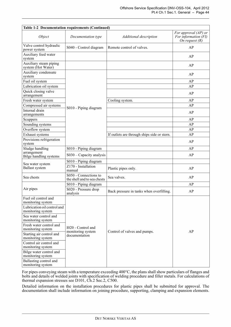
Offshore Service Specification DNV-OSS-104, April 2012Pt.4 Ch.1 Sec.1. General – Page 44
For pipes conveying steam with a temperature exceeding 400°C, the plans shall show particulars of flanges andbolts and details of welded joints with specification of welding procedure and filler metals. For calculations ofthermal expansion stresses see D101, Ch.2 Sec.2, C500.Detailed information on the installation procedures for plastic pipes shall be submitted for approval. Thedocumentation shall include information on joining procedure, supporting, clamping and expansion elements.
Valve control hydraulic power system S040 - Control diagram Remote control of valves. AP
Auxiliary feed water system AP
Auxiliary steam piping system (Hot Water) AP
Auxiliary condensate system
S010 - Piping diagram
AP
Fuel oil system APLubrication oil system APQuick closing valve arrangement AP
Fresh water system Cooling system. APCompressed air systems APInternal drain arrangements AP
Scuppers APSounding systems APOverflow system APExhaust systems If outlets are through ships side or stern. APProvisions refrigeration system AP
Sludge handling arrangementBilge handling systems
S010 - Piping diagram AP
S030 – Capacity analysis AP
Sea water systemBallast system
S010 - Piping diagramZ170 - Installation manual Plastic pipes only. AP
Sea chests S050 - Connections to the shell and to sea chests Sea valves. AP
Air pipesS010 - Piping diagram APS020 - Pressure drop analysis Back pressure in tanks when overfilling. AP
Fuel oil control and monitoring system
I020 - Control and monitoring system documentation
Control of valves and pumps. AP
Lubrication oil control and monitoring systemSea water control and monitoring systemFresh water control and monitoring systemStarting air control and monitoring systemControl air control and monitoring systemBilge water control and monitoring systemBallasting control and monitoring system
Table 1-2 Documentation requirements (Continued)
Object Documentation type Additional description For approval (AP) or For information (FI)
On request (R)
DET NORSKE VERITAS AS

Offshore Service Specification DNV-OSS-104, April 2012Pt.4 Ch.1 Sec.2. Principles – Page 45
Section 2. PrinciplesThe machinery shall be so arranged that inadvertent operation leading to reduced safety of the unit orinstallation or personnel, cannot occur as a consequence of one single operational error.The machinery and piping systems shall be arranged to prevent sea water, stored hydrocarbons or chemicals orballast from reaching dry spaces of the installation or stored hydrocarbons or chemicals from being dischargedoverboard as a consequence of inadvertent operations. Measures shall also be taken to prevent inadvertentmovement of ballast or stored fluids internally within these systems.Systems and tanks shall be so arranged that leakage or operation of valves will not directly lead to increasedrisk of damage to machinery, installation or personnel due to mixing of different fluids.Machinery, boilers and associated piping systems shall be so installed and protected as to reduce to a minimumany danger to persons onboard, due regard being paid to moving parts, hot surfaces and other hazards.Units or installations with ballast water treatment systems installed in order to meet the requirements of theBallast Water Management Convention shall follow the requirements of Ship Rules Pt.6 Ch.18 Sec.4.
2.1 Component designWhere no specific requirements are given in these standards regarding dimensioning and choice of materials,generally recognized standards and engineering principles may be applied.If acceptable accuracy cannot be obtained by strength calculations, special tests for the determination of thestrength of the design may be required.When it is of essential significance for the safety of the unit or installation that the function of a component ismaintained as long as possible in the event of fire, materials with high heat resistance shall be used.Materials with low heat resistance shall not be used in components where fire may cause outflow of flammableor health hazardous fluids, flooding of any watertight compartment or destruction of watertight integrity.
Guidance note:Materials with high heat resistance are materials having a melting point greater than 925°C. Materials with low heatresistance are all other materials. Deviations from the above requirement will be subject to special considerations.
---e-n-d---of---G-u-i-d-a-n-c-e---n-o-t-e---
Section 3. Valves
3.1 Design and testsRequirements regarding the design of valves are given in OS-D101, Ch.2 Sec.2 E100. Required hydrostatictests are described in E200.
3.2 InstallationRequirements regarding the installation of valves are given in OS-D101, Ch.2 Sec.1 A800
3.3 OperationOpen or closed position of valves shall be easily visible. If a valve's function in the system is not evident, thereshall be adequate information on a name plate attached to the valve. Other requirements regarding the operationof valves are given in OS-D101, Ch.2 Sec.1 A700.
Section 4. Piping
4.1 DesignMarine piping systems include the following:
— ballast system— bilge system— drains system— air/overflow systems— sounding system— cooling system— lubricating oil system— fuel oil system— thermal oil system— feed water and condensate systems— steam system— hydraulic system
DET NORSKE VERITAS AS
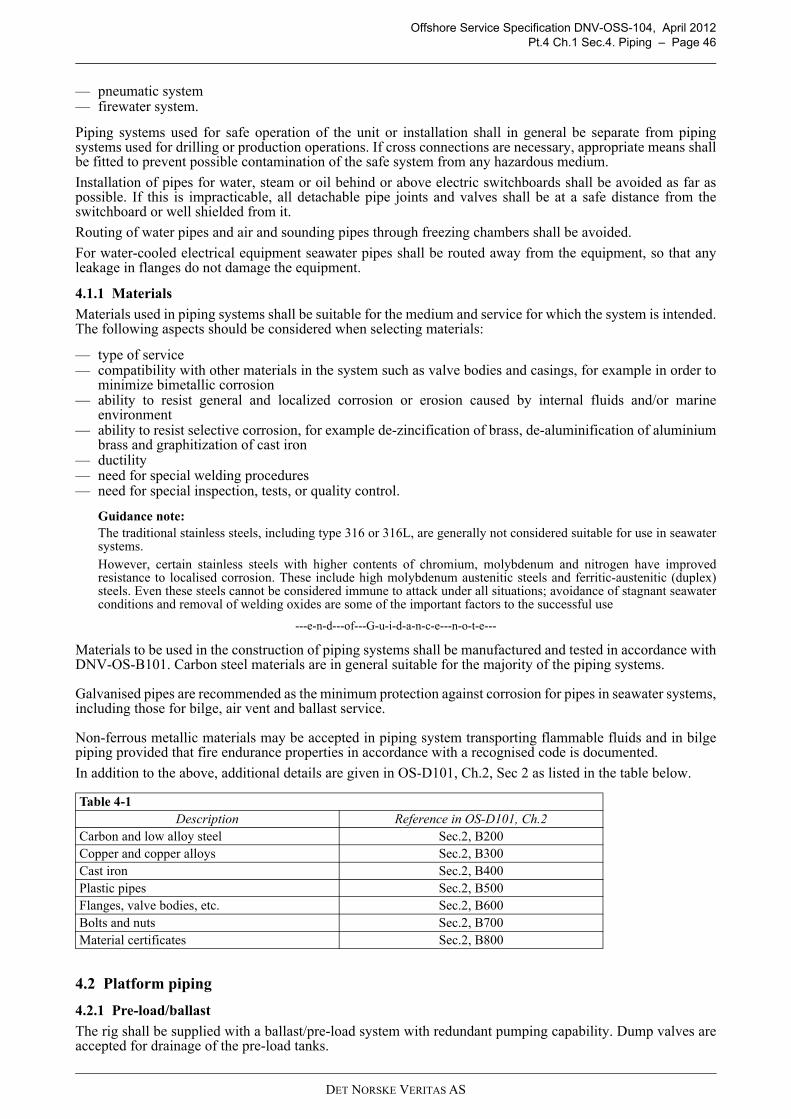
Offshore Service Specification DNV-OSS-104, April 2012Pt.4 Ch.1 Sec.4. Piping – Page 46
— pneumatic system— firewater system.
Piping systems used for safe operation of the unit or installation shall in general be separate from pipingsystems used for drilling or production operations. If cross connections are necessary, appropriate means shallbe fitted to prevent possible contamination of the safe system from any hazardous medium.
Installation of pipes for water, steam or oil behind or above electric switchboards shall be avoided as far aspossible. If this is impracticable, all detachable pipe joints and valves shall be at a safe distance from theswitchboard or well shielded from it.
Routing of water pipes and air and sounding pipes through freezing chambers shall be avoided.
For water-cooled electrical equipment seawater pipes shall be routed away from the equipment, so that anyleakage in flanges do not damage the equipment.
4.1.1 Materials
Materials used in piping systems shall be suitable for the medium and service for which the system is intended.The following aspects should be considered when selecting materials:
— type of service — compatibility with other materials in the system such as valve bodies and casings, for example in order to
minimize bimetallic corrosion — ability to resist general and localized corrosion or erosion caused by internal fluids and/or marine
environment — ability to resist selective corrosion, for example de-zincification of brass, de-aluminification of aluminium
brass and graphitization of cast iron — ductility — need for special welding procedures — need for special inspection, tests, or quality control.
Guidance note:The traditional stainless steels, including type 316 or 316L, are generally not considered suitable for use in seawatersystems.However, certain stainless steels with higher contents of chromium, molybdenum and nitrogen have improvedresistance to localised corrosion. These include high molybdenum austenitic steels and ferritic-austenitic (duplex)steels. Even these steels cannot be considered immune to attack under all situations; avoidance of stagnant seawaterconditions and removal of welding oxides are some of the important factors to the successful use
---e-n-d---of---G-u-i-d-a-n-c-e---n-o-t-e---
Materials to be used in the construction of piping systems shall be manufactured and tested in accordance withDNV-OS-B101. Carbon steel materials are in general suitable for the majority of the piping systems.
Galvanised pipes are recommended as the minimum protection against corrosion for pipes in seawater systems,including those for bilge, air vent and ballast service.
Non-ferrous metallic materials may be accepted in piping system transporting flammable fluids and in bilgepiping provided that fire endurance properties in accordance with a recognised code is documented.
In addition to the above, additional details are given in OS-D101, Ch.2, Sec 2 as listed in the table below.
4.2 Platform piping
4.2.1 Pre-load/ballast
The rig shall be supplied with a ballast/pre-load system with redundant pumping capability. Dump valves areaccepted for drainage of the pre-load tanks.
Table 4-1 Description Reference in OS-D101, Ch.2
Carbon and low alloy steel Sec.2, B200Copper and copper alloys Sec.2, B300Cast iron Sec.2, B400Plastic pipes Sec.2, B500Flanges, valve bodies, etc. Sec.2, B600Bolts and nuts Sec.2, B700Material certificates Sec.2, B800
DET NORSKE VERITAS AS

Offshore Service Specification DNV-OSS-104, April 2012Pt.4 Ch.1 Sec.4. Piping – Page 47
In addition, the general requirements of DNV-OS-D101 Ch.2, Sec.3 B as listed in Table 4-2 shall be compliedwith.
4.2.2 Bilge and drainageThe unit or installation shall be equipped with 100% redundancy in bilge pumping system and means fordraining engine room, all compartments and watertight sections. Compartments containing liquids such ascooling water, oil fuel or stored produced liquid are to have their own separate pumping system.Again, the general requirement in DNV-OS-D101 Ch.2, Sec.3 B as listed in Table 4-2 shall be complied with.
4.2.3 Raw water systemsIf the raw water system supplies water to essential systems, such as fire water systems or cooling water, systemand installation requirements are to be as required for the essential system. The following raw water system requirement applies:
1) A suitable isolation valve/valves to be provided to be able to isolate one of raw water pump systems 2) In case of leg well suction, hoses may be permitted provided they are adequately supported. Hoses to be
fire protected according IMO Res. A.753(18) L3 and protected from relevant fire scenarios1) except whena single incident will not impair the required raw water capacity.
3) Suction points (if both is fitted on one leg) to be at different heights (or caissons to be adequately protected).
Guidance note:Submersible raw water pumps installed on a hose reel may be considered case to case. The hose reel to be located toensure that a single incident would not damage both. Collapsible type hoses are not considered acceptable. The fireresistance of hoses as for leg well suction.
---e-n-d---of---G-u-i-d-a-n-c-e---n-o-t-e---
4.2.4 Drag chainsHoses in drag chain are to be fire protected according IMO Res. A.753(18) L3 and protected from relevant firescenarios2),
1) Reference is made to USCG PFM 1-98: Policy File Memorandum on the Fire Performance Requirements for Plastic Pipe per IMOResolution A.753(18).
2) Reference is made to USCG PFM 1-98: Policy File Memorandum on the Fire Performance Requirements for Plastic Pipe per IMOResolution A.753(18).
Table 4-2 Description Reference in DNV-OS-D101 Ch.2, Sec.3
Basic requirements Sec.3, B100Ballast systems Sec.3, B200Drainage of dry compartments below main deck Sec.3, B300Drainage of dry compartments above main deck Sec.3, B400Pumping and piping arrangement Sec.3, B500Bilge pipes Sec.3, B600Bilge pumps Sec.3, B700Bilge wells, mud boxes, valves etc. Sec.3, B800
DET NORSKE VERITAS AS

Offshore Service Specification DNV-OSS-104, April 2012Pt.4 Ch.1 Sec.4. Piping – Page 48
4.2.5 Air, overflow and sounding
Air, overflow and sounding are to be installed according OS-D101, Ch.2, Sec.3 F as detailed below.
4.2.6 Storage and transfer systems for helicopter fuels
If installed, tanks and pipe systems for the storage and transfer systems for helicopter fuels have to comply toOS-D101, Ch.2, Sec.3 G.
4.3 Machinery pipingRedundancy capacity of components shall be as specified in the requirements for the different systems.
Applied to piping systems this implies that more than one pump unit shall be installed when failure of such aunit will result in loss of a main function.
The capacity shall normally be sufficient to cover demands at maximum continuous load on the main functionwhen any pump unit is out of service.
4.3.1 Cooling system
Cooling systems in self-elevating units or installations shall be so arranged that the supply of cooling water tothe generator prime movers will not be affected, even if the fire pumps are in operation, during raising andlowering of the installation. In such events the cooling water may be supplied from a storage tank.
More detailed requirements are given in OS-D101, Ch.2 Sec.4 B.
4.3.2 Lubrication oil system
Lubricating oil systems shall be separated from other systems. This requirement does not apply to hydraulicgoverning and maneuvering systems for auxiliary engines.
Other requirements are given in OS-D101, Ch.2 Sec.4 C as detailed below.
4.3.3 Fuel oil system
Requirements for the fuel oil system are given in OS-D101, Ch.2 Sec.4 D, as detailed in the table below.
Table 4-3 Description Reference in OS-D101, Ch.2, Sec.3
Arrangement of air pipes Sec.3, F100Air pipes, sectional area Sec.3, F200Overflow pipes, arrangement Sec.3, F300Overflow pipes, sectional area Sec.3, F400Sounding arrangements Sec.3, F500Sounding pipes, sectional area Sec.3, F600
Table 4-4 Description Reference in OS-D101, Ch.2, Sec.4
Lubricating oil pre-treatment arrangement Sec.4, C200Lubricating oil supply Sec.4, C300Remote shut-off arrangement for lubricating oil tanks Sec.4, C400
Table 4-5 Description Reference in OS-D101, Ch.2, Sec.4
Flash point of fuel oil Sec.4, D100Fuel oil tanks Sec.4, D200Fuel oil piping Sec.4, D300Arrangement of valves and fittings Sec.4, D400Remotely controlled shut-off arrangement for fuel oil tanks Sec.4, D500Fuel oil pre-heaters Sec.4, D600Fuel oil pre-treatment arrangement Sec.4, D700Drip trays Sec.4, D800Oil filters Sec.4, D900Various requirements Sec.4, D1000
DET NORSKE VERITAS AS
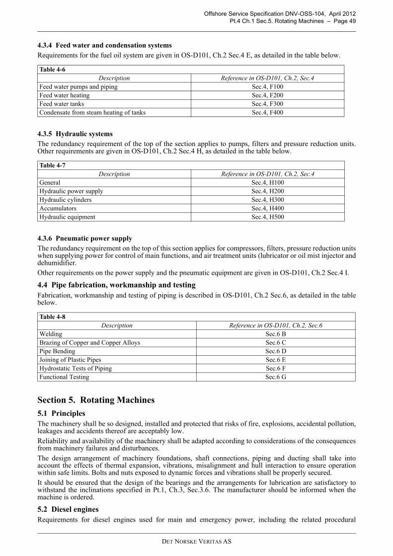
Offshore Service Specification DNV-OSS-104, April 2012Pt.4 Ch.1 Sec.5. Rotating Machines – Page 49
4.3.4 Feed water and condensation systemsRequirements for the fuel oil system are given in OS-D101, Ch.2 Sec.4 E, as detailed in the table below.
4.3.5 Hydraulic systemsThe redundancy requirement of the top of the section applies to pumps, filters and pressure reduction units.Other requirements are given in OS-D101, Ch.2 Sec.4 H, as detailed in the table below.
4.3.6 Pneumatic power supplyThe redundancy requirement on the top of this section applies for compressors, filters, pressure reduction unitswhen supplying power for control of main functions, and air treatment units (lubricator or oil mist injector anddehumidifier.Other requirements on the power supply and the pneumatic equipment are given in OS-D101, Ch.2 Sec.4 I.
4.4 Pipe fabrication, workmanship and testing Fabrication, workmanship and testing of piping is described in OS-D101, Ch.2 Sec.6, as detailed in the tablebelow.
Section 5. Rotating Machines
5.1 PrinciplesThe machinery shall be so designed, installed and protected that risks of fire, explosions, accidental pollution,leakages and accidents thereof are acceptably low.Reliability and availability of the machinery shall be adapted according to considerations of the consequencesfrom machinery failures and disturbances.The design arrangement of machinery foundations, shaft connections, piping and ducting shall take intoaccount the effects of thermal expansion, vibrations, misalignment and hull interaction to ensure operationwithin safe limits. Bolts and nuts exposed to dynamic forces and vibrations shall be properly secured.It should be ensured that the design of the bearings and the arrangements for lubrication are satisfactory towithstand the inclinations specified in Pt.1, Ch.3, Sec.3.6. The manufacturer should be informed when themachine is ordered.
5.2 Diesel enginesRequirements for diesel engines used for main and emergency power, including the related procedural
Table 4-6 Description Reference in OS-D101, Ch.2, Sec.4
Feed water pumps and piping Sec.4, F100Feed water heating Sec.4, F200Feed water tanks Sec.4, F300Condensate from steam heating of tanks Sec.4, F400
Table 4-7 Description Reference in OS-D101, Ch.2, Sec.4
General Sec.4, H100Hydraulic power supply Sec.4, H200Hydraulic cylinders Sec.4, H300Accumulators Sec.4, H400Hydraulic equipment Sec.4, H500
Table 4-8 Description Reference in OS-D101, Ch.2, Sec.6
Welding Sec.6 BBrazing of Copper and Copper Alloys Sec.6 CPipe Bending Sec.6 DJoining of Plastic Pipes Sec.6 EHydrostatic Tests of Piping Sec.6 FFunctional Testing Sec.6 G
DET NORSKE VERITAS AS

Offshore Service Specification DNV-OSS-104, April 2012Pt.4 Ch.1 Sec.5. Rotating Machines – Page 50
requirements for certification and testing are described in DNV Ship Rules, Pt.4, Ch.3, Sec.1 as detailed in thetable below.
5.3 Starting arrangements
5.3.1 Capacity
Starting systems for internal combustion engines shall have capacity for 3 starts each. The duration of eachstarting shall be minimum 10 s. If a starting system serves two or more engines, the capacity of the system shallbe the sum of the capacity requirements.
Additional requirements to the starting system for generator sets arranged as standby generators and/orarranged for starting in a black-out situation are given in Chapter 2 4.1.
Requirements to starting of emergency generators are given below. Drivers for fire pumps required to be fedfrom emergency generator shall follow the same starting requirements as for emergency generators.
5.3.2 Pneumatic
Compressors shall be installed with total capacity sufficient for charging air receivers of capacities specifiedabove from atmospheric to full pressure in the course of one (1) hour.
Two or more compressors of total capacity as specified above shall be installed. The capacity shall beapproximately equally shared between the compressors. At least one of the compressors shall be independently(not direct connected to the engine) driven.
Engines started by compressed air shall have at least two independent starting air receivers of about equalcapacity.
In order to protect starting air mains against explosion arising from improper functioning of starting valve, thefollowing devices shall be fitted:
— an isolation non-return valve or equivalent at the starting air supply connection to each engine— a bursting disc or flame arrester in way of the starting valve of each cylinder for direct reversing engines
having a main starting manifold— at the supply inlet to the starting air manifold for non-reversing engines.
The bursting discs or flame arresters may be omitted for engines having a bore not exceeding 230 mm.
The pipes and valves, including the non-return valve, shall be designed to withstand the possible back pressureif a starting valve remains open.
Use of flexible hoses in the starting air system is only permitted where necessary in order to allow for relativemovements. Flexible hoses with their couplings shall be type approved, see Ch.6 Sec.6 D.
5.3.3 Electric
When electric starting arrangement for auxiliary engines is used, there shall be at least two separately installedbatteries, connected by separate electric circuits arranged such that parallel connection is not possible. Eachbattery shall be capable of starting the engine when in cold and ready to start condition.
Starting arrangements for two or more main engines shall be divided between the two batteries and connectedby separate circuits.
The batteries shall be installed in separate boxes or lockers or in a common battery room with separate shelves(not above each other).
The capacity of starting batteries shall comply with capacity requirements as given on the beginning of thissection. If the starting batteries are also used for supplying other consumers, the capacity shall be increasedaccordingly.
Description Reference in DNV Ship Rules, Pt.4, Ch.3, Sec.1General Sec.1 ADesign Sec.1 BTesting and Inspection Sec.1 CWorkshop Testing Sec.1 DControl and Monitoring Sec.1 EArrangement Sec.1 FVibration Sec.1 GInstallation Inspections Sec.1 HShipboard Testing Sec.1 I
DET NORSKE VERITAS AS
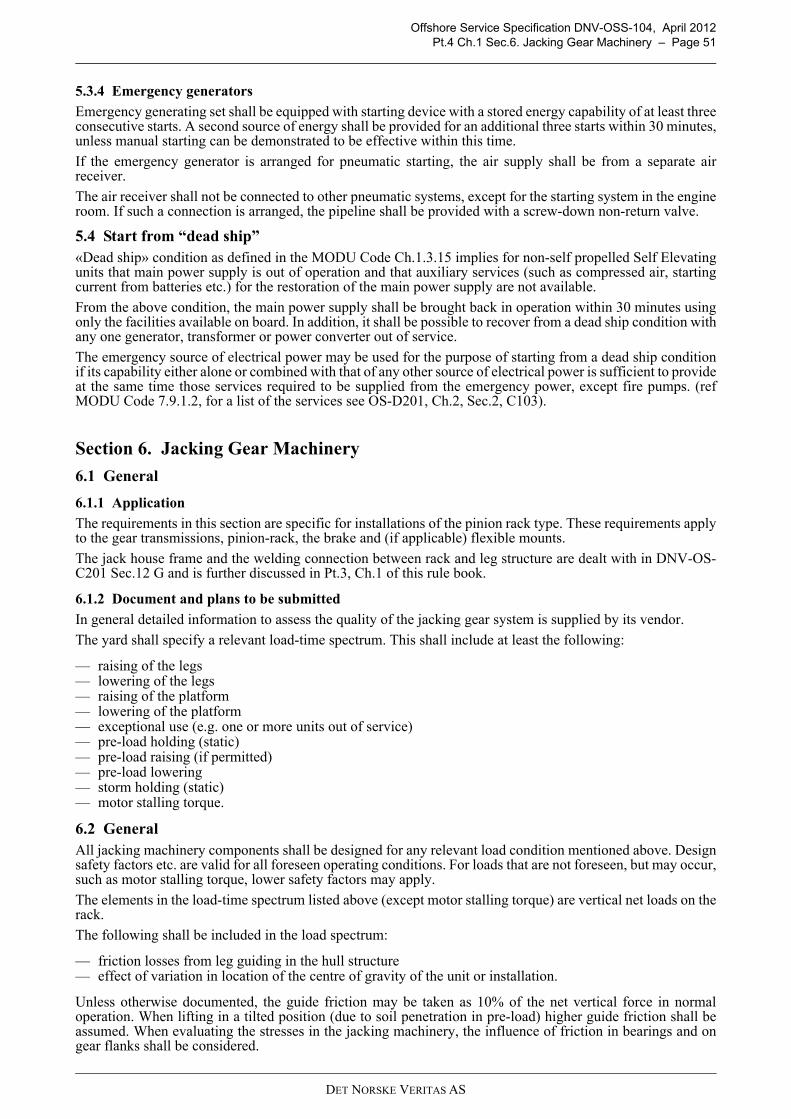
Offshore Service Specification DNV-OSS-104, April 2012Pt.4 Ch.1 Sec.6. Jacking Gear Machinery – Page 51
5.3.4 Emergency generators
Emergency generating set shall be equipped with starting device with a stored energy capability of at least threeconsecutive starts. A second source of energy shall be provided for an additional three starts within 30 minutes,unless manual starting can be demonstrated to be effective within this time.
If the emergency generator is arranged for pneumatic starting, the air supply shall be from a separate airreceiver.
The air receiver shall not be connected to other pneumatic systems, except for the starting system in the engineroom. If such a connection is arranged, the pipeline shall be provided with a screw-down non-return valve.
5.4 Start from “dead ship”«Dead ship» condition as defined in the MODU Code Ch.1.3.15 implies for non-self propelled Self Elevatingunits that main power supply is out of operation and that auxiliary services (such as compressed air, startingcurrent from batteries etc.) for the restoration of the main power supply are not available.
From the above condition, the main power supply shall be brought back in operation within 30 minutes usingonly the facilities available on board. In addition, it shall be possible to recover from a dead ship condition withany one generator, transformer or power converter out of service.
The emergency source of electrical power may be used for the purpose of starting from a dead ship conditionif its capability either alone or combined with that of any other source of electrical power is sufficient to provideat the same time those services required to be supplied from the emergency power, except fire pumps. (refMODU Code 7.9.1.2, for a list of the services see OS-D201, Ch.2, Sec.2, C103).
Section 6. Jacking Gear Machinery
6.1 General
6.1.1 Application
The requirements in this section are specific for installations of the pinion rack type. These requirements applyto the gear transmissions, pinion-rack, the brake and (if applicable) flexible mounts.
The jack house frame and the welding connection between rack and leg structure are dealt with in DNV-OS-C201 Sec.12 G and is further discussed in Pt.3, Ch.1 of this rule book.
6.1.2 Document and plans to be submitted
In general detailed information to assess the quality of the jacking gear system is supplied by its vendor.
The yard shall specify a relevant load-time spectrum. This shall include at least the following:
— raising of the legs— lowering of the legs— raising of the platform— lowering of the platform— exceptional use (e.g. one or more units out of service)— pre-load holding (static)— pre-load raising (if permitted)— pre-load lowering— storm holding (static)— motor stalling torque.
6.2 General All jacking machinery components shall be designed for any relevant load condition mentioned above. Designsafety factors etc. are valid for all foreseen operating conditions. For loads that are not foreseen, but may occur,such as motor stalling torque, lower safety factors may apply.
The elements in the load-time spectrum listed above (except motor stalling torque) are vertical net loads on therack.
The following shall be included in the load spectrum:
— friction losses from leg guiding in the hull structure— effect of variation in location of the centre of gravity of the unit or installation.
Unless otherwise documented, the guide friction may be taken as 10% of the net vertical force in normaloperation. When lifting in a tilted position (due to soil penetration in pre-load) higher guide friction shall beassumed. When evaluating the stresses in the jacking machinery, the influence of friction in bearings and ongear flanks shall be considered.
DET NORSKE VERITAS AS

Offshore Service Specification DNV-OSS-104, April 2012Pt.4 Ch.1 Sec.6. Jacking Gear Machinery – Page 52
Jacking machinery (including pinion-rack) shall be designed so that an overload failure occurs in openmachinery prior to enclosed machinery. This means that conditions such as e.g. a motor stalling or lifting witha locked brake are to cause clearly visible deformation in easily accessible parts such as pinion (preferably) orrack before any critical failure occurs in an enclosed gearbox.
When a design is documented by means of tests in lieu of calculations, or by combinations thereof, lower safetyfactors than those required by calculations may be accepted. The level will be considered on the basis of theextent of the testing and the acceptance criteria for the various parts after the test. When units or parts of unitsare tested, normally the whole load spectrum shall be applied and each load level shall be multiplied with therequired safety factor. When different safety factors apply, such as for tooth root strength and flank durability,the highest (i.e. tooth root strength) shall be used for testing purposes. (Due to the elevated loads, some flankdeterioration is considered acceptable in this case).
The jacking machinery shall be designed to avoid self-locking when descending. The minimum total efficiencyin lifting mode is 2/3. The total efficiency shall include motor, gear transmission and pinion-rack.
6.3 MaterialsMaterials in forged and cast components are to satisfy the requirements given in DNV-OS-B101, Ch.2 Sec.3Table B2 and Sec.4 Table B2. For materials with yield strength value higher than given in the table, the materialproperties are equal to the highest tabulated values. Materials in fixation chocks in the fixation system (ifinstalled) are to be equivalent to the material in the racks.
6.4 ArrangementThe jacking units shall be arranged so that they can be removed individually for servicing.Power supply are to arranged so that no single failure prevents the jacking operation. The jacking machinerywith control system is defined as an important system as defined in DNV-OS-D202, Ch.1 Sec.1 C209.In case of failures, the jacking systems shall be designed such that repair (incl. minor replacements) is possiblewithin 3 hrs. An FMEA according to DNV-OS-D202, Ch.3 Sec.1 Table B2 is to be carried out.
The jacking units shall be supported in such a way that elastic jack-house frame deflections are not harmful tothe pinion-rack mesh. The jack-house frame and leg-rack shall have dimensional tolerances that permits aninvolute gear mesh (i.e. contact ratio is above unity) between pinion and rack under all operating conditions.Flexible (sandwich) rubber pads shall be protected by an oil based coating.
The motors shall be provided with a possibility for mechanical wind-up, e.g. a square free-shaft end for crankapplication.
An interlock shall be provided between electric motors and fixation rack system (if any), in order to preventpower supply to the motors when the fixation rack is engaged.
6.5 Gearing
6.5.1 GeneralDetails on calculation of gearing are given in Classification Note 41.2. This contains information on calculationof tooth root strength (fractures or deformation) and flank surface durability (pitting, spalling and casecrushing) and scuffing for enclosed gear units.
The following minimum safety factors apply (but due consideration shall be given to the principles given in 6.2:
— Tooth root strength, applicable to both enclosed and open gearing:
— safety against accumulated fatigue due to all lifting and descending loads SF = 1.5— safety against static loads as storm holding or pre-load holding SF = 1.35— safety against one motor stalling SF = 1.2.
— Flank surface durability, applicable to enclosed gearing, except for case crushing (surface hardenedgearing) which also applies to open gears:
— safety against accumulated fatigue due to all lifting and descending loads SH = 1.0— safety against case crushing under static loads and one motor stalling SH = 1.0.
— Scuffing, applicable to enclosed gearing:
— safety SS = 1 except for motor stalling.
Welded gears shall be stress relieved. Welds that suffer a stress variation during the rotation shall be designedto prevent (low cycle) fatigue.The permissible stress range in a full penetration weld with a smooth (accessible) backside is 0.5 times the yieldstrength of the softer material. For inaccessible backside or non-full penetration welds the permissible stressrange is 0.2 times the yield strength of the softer material. The stress range shall be determined by finite element
DET NORSKE VERITAS AS

Offshore Service Specification DNV-OSS-104, April 2012Pt.4 Ch.1 Sec.6. Jacking Gear Machinery – Page 53
method analyses and is to consider any stress concentration.
Guidance note:
To facilitate asset management during the operational use of the unit, it is recommended that the fatigue lifecalculations as done above are made available for operational users.
---e-n-d---of---G-u-i-d-a-n-c-e---n-o-t-e---
6.5.2 Pinion rack
For pinions the tooth profile shall be specified on a drawing.
The safety factors of the gearing apply for the pinions and racks as well, with exception of rack tooth rootstrength for storm holding and motor stalling where tooth deformation is acceptable.
For calculation of tooth root stresses of pinion and rack, load application at the tooth tip shall be assumed.Further guidance can be found in Appendix C in Classification Note 41.2.
6.5.3 Gear casings and bearing structure
Welded gear casings and supporting structure around bearings shall be stress relieved.
The casings and bearing structures shall be designed to prevent deflections that may be harmful for the gearing.
The design shall enable inspections of the gearing and plain bearings. For parallel shaft gears this meansinspection openings, and for epicyclic gears openings for access with boroscope. In addition, it is recommendedthat appropriate oil sample points are installed.
6.5.4 Shafts and connections
Connections as shrink fitting, bolted wheels, flange bolts, splines, keys, etc. shall fulfil the criteria given inClassification Note 41.2.
Shafts shall be designed to have safety against yielding that is consistent with the tooth root strength criteria in6.2. Combined bending and torsion shall be considered. Stress concentration factors may be taken fromrelevant literature or from the Classification Note 41.2.
Special consideration shall be given to high speed shafts accumulating more than 104 cycles.
6.5.5 Bearings
Ball and roller bearings shall have a minimum L10a (ISO 281) life time that is suitable with regard to thespecified overhaul intervals. The influence of the lubrication oil film may be taken into account for L10a,provided that the necessary conditions, in particular cleanliness, are fulfilled.
The surface pressure (on projected area) in plain bearings shall not exceed 50% of the yield strength of thebearing material when the maximum load is applied. The bearings and lubrication are also to be designed toavoid wear that could be harmful for the gear meshes.
6.6 Brakes
A shaft brake shall be provided. This is to engage automatically in the event of power failure to the jackingmachinery.
The brake is to be designed to operate at least at a shaft speed corresponding to the maximum operationaljacking speed + 10%.
The static brake friction torque shall not be less than 1.3 times the maximum torque at the brake position.
6.7 Flexible mountings
Flexible mounting of the jacking units will be specially considered. Possibilities for replacement of theseflexible mountings are to be taken into account.
6.8 Control and monitoring
The following control and monitoring arrangements are required:
a) Remote indication and alarm if a brake is not released when power applied to the motors. The brake alarmshall be given by an independent mechanical sensor.
b) Remote indication and alarm for overheating of an electric motor.
c) A permanent remote indication of loads during jacking and retrieval shall be provided. For a lattice leg unitthe load per chord is as a minimum to be presented. Alarm signal to be given when maximum load isexceeded.
DET NORSKE VERITAS AS

Offshore Service Specification DNV-OSS-104, April 2012Pt.4 Ch.1 Sec.6. Jacking Gear Machinery – Page 54
6.9 Testing & inspection
6.9.1 GeneralThe testing of the jacking gear system shall in general consist of workshop testing, inspection after installationand testing on board. A complete overview is to be found in DNV’s Shipping Rules, Pt.4, Ch.4, Sec.2 C asfollows:
6.9.2 Workshop testingSpin test and contact pattern test shall be carried out according to the Rules for Classification of Ships Pt.4Ch.4. Sec 2D.
6.9.3 Installation inspectionThe alignment between the pinions and rack shall be checked both longitudinally and with regard to distancebetween pinion centre and rack.The gearing box shall be inspected on the following (with reference to Rules for Classification of Ships Pt.4Ch.4:
— shaft alignment, see Sec.1 H300— fastening of propulsion gearboxes (stoppers and bolt tightening)— flushing, applicable if the system is opened during installation. Preferably with the foreseen gear oil. If— flushing oil is used, residual flushing oil shall be avoided.— lubrication oil shall be as specified (viscosity and FZG class) on maker’s list— pressure tests to nominal pressure (for leakage) where cooler, filters or piping is mounted onboard— tooth contact pattern, see 202.
6.9.4 Testing on boardThe testing on board is part of the jacking trials as described in Pt.6, Ch.4.
Table 6-1 Description Reference in DNV’s Shipping Rules, Pt.4, Ch.4, Sec.2 C
Certification of parts Sec.2, C100Pinion and wheels Sec.2, C200Welded gear designs Sec.2, C300Ancillaries Sec.2, C400Assembling Sec.2, C500
DET NORSKE VERITAS AS
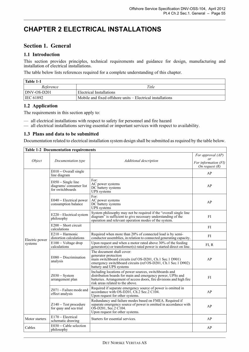
Offshore Service Specification DNV-OSS-104, April 2012Pt.4 Ch.2 Sec.1. General – Page 55
CHAPTER 2 ELECTRICAL INSTALLATIONS
Section 1. General
1.1 IntroductionThis section provides principles, technical requirements and guidance for design, manufacturing andinstallation of electrical installations.
The table below lists references required for a complete understanding of this chapter.
1.2 ApplicationThe requirements in this section apply to:
— all electrical installations with respect to safety for personnel and fire hazard— all electrical installations serving essential or important services with respect to availability.
1.3 Plans and data to be submittedDocumentation related to electrical installation system design shall be submitted as required by the table below.
Table 1-1 Reference Title
DNV-OS-D201 Electrical InstallationsIEC 61892 Mobile and fixed offshore units – Electrical installations
Table 1-2 Documentation requirements
Object Documentation type Additional description
For approval (AP) or
For information (FI)On request (R)
Electric power systems
E010 − Overall single line diagram AP
E050 − Single line diagrams/ consumer list for switchboards
For:AC power systemsDC battery systemsUPS systems
AP
E040 − Electrical power consumption balance
For:AC power systemsDC battery systemsUPS systems
AP
E220 − Electrical system philosophy
System philosophy may not be required if the “overall single line diagram” is sufficient to give necessary understanding of the operation and relevant operation modes of the system.
FI
E200 − Short circuit calculations FI
E210 − Harmonic distortion calculations
Required when more than 20% of connected load is by semi-conductor assemblies, in relation to connected generating capacity. FI
E100 − Voltage drop calculations
Upon request and when a motor rated above 30% of the feeding generator(s) or transformer(s) rated power is started direct on line. FI, R
E080 − Discrimination analysis
The document shall cover:generator protectionmain switchboard circuits (ref OS-D201, Ch.1 Sec.1 D901)emergency switchboard circuits (ref OS-D201, Ch.1 Sec.1 D902)battery and UPS systems
AP
Z030 − System arrangement plan
Including locations of power sources, switchboards and distribution boards for main and emergency power, UPSs and batteries. Arrangement of access doors, fire divisions and high fire risk areas related to the above.
FI
Z071 − Failure mode and effect analysis
Required if separate emergency source of power is omitted in accordance with OS-D201, Ch.2 Sec.2 C104.Upon request for other systems.
AP
Z140 − Test procedure for quay and sea trial
Redundancy and failure modes based on FMEA. Required if separate emergency source of power is omitted in accordance with OS-D201, Sec.2 C104.Upon request for other systems.
AP
Motor starters E170 − Electrical schematic drawing Starters for essential services. AP
Cables E030 − Cable selection philosophy AP
DET NORSKE VERITAS AS

Offshore Service Specification DNV-OSS-104, April 2012Pt.4 Ch.2 Sec.2. Principles – Page 56
For documentation requirements of electrical equipment required to be delivered with DNV Product Certificatesee Pt.5 Sec.4.1.
Section 2. PrinciplesThe following principles apply to electrical installations:
— Electrical installations shall be such that the safety of passengers, crew and unit from electrical hazards, isensured.
— There shall be two mutually independent and self contained electric power supply systems on board:
— main electric power supply system— emergency electric power supply system. Exceptions are given in DNV-OS-D201, Ch.2 Sec.2 C104.
— Services required for normal operation of the offshore unit shall be operable with the emergency electricalpower generation and distribution system being unavailable, unless such services are permitted to bepowered by emergency electrical power supply only.
— All consumers that support functions required to be available in normal operation, shall be supplied fromdistribution systems independent of the emergency electrical power supply system. Exemptions are madefor one of redundant consumers required for dead ship recovery.
— All consumers required to be available in emergency operation shall be supplied from distribution systemsindependent of the main electric power supply system.
— Consumers required having both main and emergency supply shall be supplied as required by relevant rulesapplicable for these consumers. The primary supply shall be from the main system.
— Offshore units without a dedicated emergency electric power supply system are accepted upon compliancewith requirements in DNV-OS-D201 Ch.2 Sec.2 C104.
Relevant specifications for system voltage, frequency and earthing are given in DNV-OS-D201, Ch.2, Sec.2as follows:
Emergency stop system
E170 − Electrical schematic drawing
Emergency stop of electrical propulsion motors, pumps and fans, showing fail to safe functionality. AP
Installation in hazardous areas
E090 − Table of Ex-installation
Based on approved area classification drawing and ESD philosophy (if relevant). AP
Installation in hazardous areas
G080 − Hazardous area classification drawing
An approved Area classification drawing where location of electric equipment in hazardous area is added (Except battery room, paint stores and gas bottle store).
FI
Lighting systems
E190 − Lighting description AP
C030 − System arrangement plan Emergency lighting arrangement AP
Table 2-1 Description Reference in DNV-OS-D201, Ch.2, Sec.2
System earthing Sec.2 A103Types of distribution system Sec.2 A104Hull return systems Sec.2 A105System voltages and frequencies Sec.2 A200Lightning protection Sec.2 I600Earthing of aluminium superstructures on steel offshore units
Sec.2 I700
DET NORSKE VERITAS AS

Offshore Service Specification DNV-OSS-104, April 2012Pt.4 Ch.2 Sec.3. Arrangements and Installation – Page 57
Section 3. Arrangements and Installation
3.1 ArrangementArrangements for electrical installations are specified in OS-D202, Ch.2, Sec.2 I as follows:
For the arrangement of batteries see 4.3.
3.2 InstallationThe following applies for installation of electrical equipment:
— All electrical equipment shall be permanently installed and “electrically safe”. This shall prevent injury topersonnel, when the equipment is handled or touched in the normal manner. (Interpretation of SOLASCh.II-1/45.1.3)
— All electrical equipment shall be selected and installed so as to avoid EMC problems. Thus preventingdisturbing emissions from equipment, or preventing equipment from becoming disturbed and affecting itsintended function(s).
— Electrical equipment shall be placed in accessible locations so that those parts, which require manualoperation, are easily accessible.
— Heat dissipating electrical equipment as for example lighting fittings and heating elements, shall be locatedand installed so that high temperature equipment parts do not damage associated cables and wiring, oraffect surrounding material or equipment, and thus become a fire hazard. (Interpretation of SOLAS Ch.II-1/45.7)
— Equipment shall be installed in such a manner that the circulation of air to and from the associatedequipment or enclosures is not obstructed. The temperature of the cooling inlet air shall not exceed theambient temperature for which the equipment is specified.
— All equipment of smaller type (luminaries, socket outlets etc.) shall be protected against mechanicaldamage either by safe location or by additional protection, if not of a rugged metallic construction.
In addition installation requirements are given in OS-D20, Ch.2 Sec.10 B as listed in the table below.
Section 4. Power Supply
4.1 Main
4.1.1 Capacity
The main power supply system shall have the capacity to supply power to all services necessary for maintainingthe offshore unit in normal operation without recourse to the emergency source of power.
There shall be component redundancy for main sources of power, transformers and power converters in themain power supply system so that with any source, transformer or power converter out of operation, the powersupply system shall be capable of supplying power to the following services:
— those services necessary to provide normal operational conditions and safety— starting the largest essential or important electric motor on board, except auxiliary thrusters, without the
Table 3-1 Description Reference in DNV-OS-D201, Ch.2, Sec.2
Ventilation Sec.2, I101Arrangement of power generation and distribution Sec.2, I102Installation of switchboards1 Sec.2, I201Arrangement for high voltage switchboard rooms Sec.2, I202Passage ways for main and emergency switchboards Sec.2, I203Distribution switchboards Sec.2, I2041 Applies for transformers as well
Table 3-2 Description Reference in OS-D201, Ch.2 Sec.10
Ventilation Sec.10, B102High voltage switchgear Sec.10, B103Passage of switchboards Sec.10, B104Transformers Sec.10, B105Heating and cooking appliances Sec.10, B106Equipment enclosure, ingress protection Sec.10, B200
DET NORSKE VERITAS AS

Offshore Service Specification DNV-OSS-104, April 2012Pt.4 Ch.2 Sec.4. Power Supply – Page 58
transient voltage and frequency variations exceeding the limits specified in DNV-OS-D201 Ch.2 Sec.2A200
— ensuring minimum comfortable conditions of habitability which shall include at least adequate services forcooking, heating, domestic refrigeration (except refrigerators for air conditioning), mechanical ventilation,sanitary and fresh water
— for a duplicated essential or important auxiliary, one being supplied non-electrically and the otherelectrically (e.g. lubricating oil pump No. 1 driven by the main engine, No. 2 by electric motor), it is notexpected that the electrically driven auxiliary is used when one generator is out of service
For “dead ship” recovery, see Ch.1, Sec.5.4.
4.1.2 Generator prime movers
Each generator shall normally be driven by a separate auxiliary engine not to be used for driven other auxiliarysystems.
Auxiliary engines shall comply with the requirements in DNV-OS-D101, Sec.5 B.Guidance note:Generators based on variable speed drives will be evaluated in each case. As a minimum, the following should beevaluated:
- availability- stability of output voltage and frequency- short circuit capability and protection.
---e-n-d---of---G-u-i-d-a-n-c-e---n-o-t-e---
4.1.3 System functionality
At least two generator sets, connected to separate main busbar sections, shall be arranged with systems forstarting in a blackout situation. However, only one standby generator may be permitted if this generator is notintended to be used for normal operation of the offshore unit.
Requirements to energy for starting and supply to auxiliaries required for starting are given in OS-D201, Ch.2,Sec.2, B202.
4.1.4 Load shedding and automatic restoration of power
The system shall be so arranged that the electrical supply to ensure safety of the offshore unit, will bemaintained or immediately restored in case of loss of any one of the generators in service. This means:
— All generators shall be equipped with automatic load shedding or other automatic means to preventsustained overload of any generator, ref. DNV-OS-D201 Ch.2 Sec.2 G101.
— Where the electrical power is normally supplied by one generator provision shall be made, upon loss ofpower, for automatic starting and connecting to the main switchboard of standby generator(s) of sufficientcapacity with automatic restarting of the essential auxiliaries, in sequential operation if required. Startingand connection to the main switchboard of the standby generator is to be preferably within 30 seconds, butin any case not more than 45 seconds, after loss of power.
— Where prime movers with longer starting time are used, this starting and connection time may be exceededupon approval from the society.
— Where more than one generating set is necessary to cover normal loads, the power supply system shall beprovided with suitable means for tripping or load reduction of consumers. If necessary, importantconsumers may be tripped in order to permit propulsion and steering and to ensure safety. If the remainingon line generators are not able to permit propulsion and steering and to ensure safety, provision shall bemade for automatic starting and connection to the main switchboard of the standby generator.
4.2 Emergency power supply systems Requirements for emergency power supply systems are given in DNV-OS-D201 Ch.2 Sec.2 C.
Table 4-1 Description Reference in DNV-OS-D201, Ch.2, Sec.2
Emergency power source Sec.2, C101Capacity Sec.2, C102Services to be supplied Sec.2, C103Independent installation of power sources Sec.2, C104Emergency switchboard Sec.2, C105Transitional source Sec.2, C200Emergency generators Sec.2, C300
DET NORSKE VERITAS AS

Offshore Service Specification DNV-OSS-104, April 2012Pt.4 Ch.2 Sec.5. Electrical Power Distribution – Page 59
4.3 Battery systemsTrip of battery by Emergency Shutdown System (ESD) shall be arranged as required by DNV-OS-A101, Sec.5.Additional requirements for rechargeable Lead Acid and NiCd batteries are given in OS-D201, Ch.2 as follows:
Requirements for installation of electrical equipment in battery rooms, lockers and boxes are given in Ch.3Sec.3., alternatively OS-D201, Ch.2, Sec.11, C205Installation of rechargeable battery types other than Lead Acid and NiCd will be evaluated case-by-case basedon the above requirements and DNV Rules for Ships Pt.6 Ch.28 - Tentative Rules for Battery Power.Installation and ventilation recommendations from the manufacturer should always be followed.
4.4 Power supply to jacking gearFor power supply to jacking gear, see Chapter 1, Section 6.
Section 5. Electrical Power DistributionRequirements to electric power distribution are given in DNV-OS-D201 Ch.2 Sec.2 F as follows:
Due to redundancy requirement for jacking machinery, the main busbar shall be subdivided into at least twoparts. So far as is practicable, the connection of generating sets and other duplicated equipment shall be equallydivided between the parts. In addition:
— For high voltage distribution systems, the main busbar sections shall be connected by circuit breaker.— For low voltage distribution systems, busbars which can be divided into at least two parts within three hours
can be accepted. (System category “repairable system” R3 as defied in Chapter 3 1.4 or DNV-OS-D202Ch.2 Sec.1 B102.)
Section 6. ProtectionRequirements to protection are given in DNV-OS-D201 Ch.2 Sec.2 G as follows:
Table 4-2 Description Reference in DNV-OS-D201, Ch.2, Sec.2
Capacity of accumulator batteries Ch.2, Sec.2 D101Battery powered systems Ch.2, Sec.2 D102Battery monitoring Ch.2, Sec.2 D103Arrangement Ch.2, Sec.2 I403Ventilation Ch.2, Sec.2 I404Charging stations for battery powered fork lift (if applicable) Ch.2, Sec.2 I405Materials for installation Ch.2, Sec.10 B302Testing Ch.2, Sec.10 B303
Table 5-1 Description Reference in DNV-OS-D201, Ch.2, Sec.2
General Sec.2, F101Consequence of single failure Sec.2, F102Division of main busbars See belowGenerator circuits Sec.2, F104Lighting Sec.2, F200Power supply to control and monitoring systems Sec.2, F300Low voltage shore connections Sec.2, F400
Table 6-1 Description Reference in DNV-OS-D201, Ch.2, Sec.2
System protection Sec.2, G100Circuit protection Sec.2, G200Generator protection Sec.2, G300Transformer protection Sec.2, G400Motor protection Sec.2, G500Battery protection Sec.2, G600Harmonic Filter protection Sec.2, G700
DET NORSKE VERITAS AS

Offshore Service Specification DNV-OSS-104, April 2012Pt.4 Ch.2 Sec.7. Control – Page 60
Section 7. ControlRequirements to control of electric equipment are given in DNV-OS-D201 Ch.2 Sec.2 H as follows:
Section 8. Electrical Equipment:In general, DNV’s electrical equipment requirements are based on IEC standard IEC 61892, part 1, “Generalrequirements and conditions”, part 2 “Systems design”, and part 3 “Equipment”. For environmental requirements, see Pt.1, Ch.3, Sec.3.Other general requirements for electrical equipment are given in OS-D201, Ch.2, Sec.3 as listed in the tablebelow.
Requirements for specific electrical equipment are given in OS-D201 Ch.2 as listed below.
Section 9. Cables
9.1 Cable selection These technical requirements for cables and cable installations are considered relevant for the system designphase of a project. However, they apply as well to the final installation on the offshore unit. Details can befound in OS-D201, Ch.2, Sec.2 J as detailed in the table below.
Table 7-1 Description Reference in DNV-OS-D201, Ch.2, Sec.2
Control circuits Sec.2, H100Control of generator sets and main power supply Sec.2, H200Main and emergency switchboard control Sec.2, H300Motor control Sec.2, H400Emergency stop Sec.2, H500
Table 8-1 Description Reference in DNV-OS-D201, Ch.2, Sec.3
Electrical parameters Sec.3, C100Maximum operating temperatures Sec.3, C200Mechanical strength Sec.3, D100Cooling and anti-condensation Sec.3, D200Termination and cable entrances Sec.3, D300Equipment protective earthing Sec.3, D400Enclosures ingress protection Sec.3, D500Clearance and creepage distances Sec.3, D600Insulation materials Sec 3, F100
Table 8-2 Description Reference in DNV-OS-D201, Ch.2
Switchgear and control gear assemblies Ch.2, Sec.4Rotating Machines Ch.2, Sec.5Power transformers Ch.2, Sec.6Semi-conductor converters Ch.2, Sec.7Miscellaneous Equipment Ch.2, Sec.8
DET NORSKE VERITAS AS

Offshore Service Specification DNV-OSS-104, April 2012Pt.4 Ch.2 Sec.9. Cables – Page 61
9.2 Cable construction and rating
The cables shall comply to the standards as described in OS-D201, Ch.2, Sec.9 as listed in the table below.
9.3 Cable routing and installations
Cable runs shall be installed well clear of substantial heat sources such as boilers, heated oil tanks, steam,exhaust or other heated pipes, unless it is ensured that the insulation type and current rating is adapted to theactual temperatures at such spaces. Other relevant requirements are given in OS-D201, Ch.2, Sec.2 and Sec.10as detailed in the table below.
Additional requirements for cables installed in hazardous areas are given in OS-D201, Ch.2, Sec.11 as detailedin the table below.
Table 9-1 Description Reference in DNV-OS-D201, Ch.2, Sec.2
Fire resistant cables Sec.2, J102Voltage rating Sec.2, J103Colour code on earthing cable Sec.2, J104Cable separation and protection Sec.2, J105Cable temperature Sec.2, J200Choice of insulation materials Sec.2, J300Rating of earth conductors Sec.2, J400Correction factors Sec.2, J500Parallel connection of cables Sec.2, J600Additional requirements for AC installations and special DC installations
Sec.2, J700
Rating of cables Sec.2, J800
Table 9-2 Description Reference in DNV-OS-D201, Ch.2, Sec.9
Application Sec.9 AGeneral cable construction Sec.9 BHigh voltage cables Sec.9 CLow voltage power cables Sec.9 DControl and instrumentation cables Sec.9 EData communication cables Sec.9 FFibre optic cables Sec.9 GInspection and testing Sec.9 H
Table 9-3 Description Reference in DNV-OS-D201, Ch.2
Separation of cables for emergency services, essential and important equipment
Sec.2, I502
Separation of main generators or main power converters cabling Sec.2, I503Routing of cables Sec.10, C200Penetrations of bulkheads and decks Sec.10, C300Fire protection measures Sec.10, C400Support and fixing of cables and cable runs Sec.10, C500Cable expansion Sec.10, C600Cable pipes Sec.10, C700Splicing of cables Sec.10, C800Termination of cables Sec.10, C900Trace or surface heating installation requirements Sec.10, C1000
Table 9-4 Description Reference in DNV-OS-D201, Ch.2, Sec.11
Cable types Sec.11, D201Fixed cable installations Sec.11, D202Flexible cables Sec.11, D203
DET NORSKE VERITAS AS
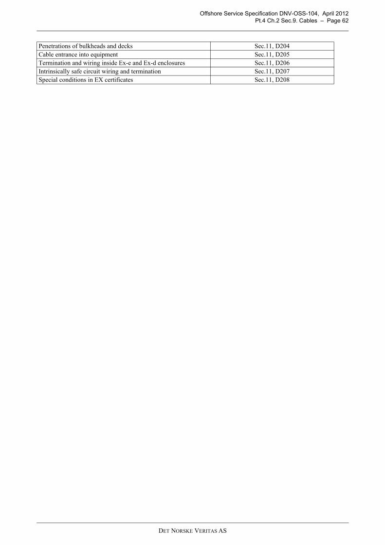
Offshore Service Specification DNV-OSS-104, April 2012Pt.4 Ch.2 Sec.9. Cables – Page 62
Penetrations of bulkheads and decks Sec.11, D204Cable entrance into equipment Sec.11, D205Termination and wiring inside Ex-e and Ex-d enclosures Sec.11, D206Intrinsically safe circuit wiring and termination Sec.11, D207Special conditions in EX certificates Sec.11, D208
DET NORSKE VERITAS AS

Offshore Service Specification DNV-OSS-104, April 2012Pt.4 Ch.3 Sec.1. General – Page 63
CHAPTER 3 AREA ARRANGEMENTS
Section 1. General
1.1 ScopeThis chapter covers the arrangement of areas in general and hazardous areas with the relevant requirements formachinery and electrical equipment.The table below lists references required for a complete understanding of this chapter.
1.2 Plans and data to be submittedDocumentation related to this chapter shall be submitted as required by the table below
Section 2. ArrangementsThe unit or installation shall be divided into different areas according to the type of activities that will be carriedout and the associated hazard potential.Areas of high risk potential shall be segregated from areas of low risk potential, and from areas containingimportant safety functions. Incident escalation between areas shall be avoided.Accommodation and other areas important for safety, such as control stations, shall be located in areasclassified as non-hazardous by location, and as far as practicable away from hazardous areas for hydrocarbonprocessing, hydrocarbon storage, wellheads, risers and drilling. The effect of prevailing winds and potential forsegregation by less hazardous areas shall also be considered for area protection.Use of firewalls, blast walls, cofferdams etc. shall be considered in cases where segregation by physicaldistance is not sufficient.Where control stations or control functions are located in LER/LIRs outside the accommodation block/safearea special precautions against gas ignition related to gas detection, ventilation and shutdown will need to beprovided.
Table 1-1 Overview of referencesReference Title
DNV-OS-A101 Safety Principles and ArrangementsDNV-OS-C301 Stability and Watertight IntegrityDNV-OS-D101 Marine and Machinery Systems and EquipmentDNV-OS-D201 Electrical InstallationsDNV-OS-D202 Automation, Safety, and Telecommunication SystemsDNV-OS-E301 Position MooringIEC 61892 Mobile and fixed offshore units – Electrical installations
Table 1-2 Documentation requirements
Object Documentation type Additional description For approval (AP) orFor information (FI)
On request (R)
Hazardous area classification
G070 - Source of release schedule FI
G080 - Hazardous area classification drawing
For:AC power systemsDC battery systemsUPS systems
AP
Ventilation systems V010 - Ducting diagram AP
Emergency escape G100 – Escape and evacuation study AP
Assembly station / muster station / temporary refuge space
Z030 – System Arrangement plan AP
Escape route G120 – Escape route drawing AP
DET NORSKE VERITAS AS

Offshore Service Specification DNV-OSS-104, April 2012Pt.4 Ch.3 Sec.3. Hazardous Areas Installations – Page 64
Specific requirements for location of equipment are given in OS-A101 Ch.2 as listed in the table below.
2.1 Electrical installationsArrangements for electrical installations are specified in OS-D201, Ch.2, Sec.2 I as listed below.
Section 3. Hazardous Areas Installations
3.1 Area classificationHazardous areas are classified as follows:
— Zone 0: in which an explosive gas atmosphere is continuously present or present for long periods. (Typicalfor continuous grade source present for more than 1000 hours a year or that occurs frequently for shortperiods).
— Zone 1: in which an explosive gas atmosphere is likely to occur in normal operation. (Typical for primarygrade source present between 10 and 1000 hours a year).
— Zone 2: in which an explosive gas atmosphere is not likely to occur in normal operation, and if it does occur,is likely to do so infrequently and will exist for a short period only. (Typical for secondary grade sourcepresent for less than 10 hours per year and for short periods only).
3.2 Battery rooms, paint stores, and welding gas bottle stores Electrical equipment installed in battery rooms lockers or boxes, paint stores or welding gas bottle stores, andin ventilation ducts serving such spaces shall be suitable for installation in zone 1 with the followingrequirements for gas group and ignition temperature:
— battery rooms: minimum gas group II C and temperature class T1 — paint stores: minimum gas group II B and temperature class T3 — welding gas bottle stores: minimum gas group II C and temperature class T2.
Cables routed through such spaces shall either be suitable for installation in hazardous area zone 1, or beinstalled in metallic conduit. Areas on open deck within 1m of inlet and exhaust ventilation openings or within 3 m of exhaust outlets withmechanical ventilation are classified as zone 2. Enclosed spaces giving access to such areas may be considered as non-hazardous, provided that:
— the door to the space is a gastight door with self-closing devices and without holding back arrangements (awatertight door is considered gastight)
— the space is provided with an acceptable, independent, natural ventilation system ventilated from a safe area— warning notices are fitted adjacent to the entrance to the space stating that the store contains flammable
liquids or gas.
Battery rooms and lockers or boxes shall be regarded as zone 2 hazardous areas with respect to access doors,lids or removable panels and possible interference with other rooms.
Table 2-1 Description Reference in OS-A101 Ch.2
Location of safety systems Sec.2, D100Location of risers and ESD valves Sec.2, D200Location of air intakes and other openings Sec.2, D300Fired heaters, combustion engines and hot surfaces Sec.2, D400Location of flares and vents Sec.2, D500Cranes and lay down areas Sec.3 FMooring systems Sec.8, B200Production and well testing Sec.8, B400
Table 2-2 Description Reference in OS-D201, Ch.2, Sec.2
Ventilation Sec.2, I101Arrangement of power generation and distribution Sec.2, I102Installation of switchboards1 Sec.2, I201Arrangement for high voltage switchboard rooms Sec.2, I202Passage ways for main and emergency switchboards Sec.2, I203Distribution switchboards Sec.2, I204
DET NORSKE VERITAS AS

Offshore Service Specification DNV-OSS-104, April 2012Pt.4 Ch.3 Sec.4. Ventilation Systems – Page 65
The fan mounted inside extract ventilation ducts shall be of non-sparking type.
3.3 Requirements for specific systems
3.3.1 Combustion enginesCombustion equipment and combustion engines shall normally not be located in hazardous areas. Where it isnecessary to house combustion engines in a hazardous area, either the equipment shall be placed in apressurized space or the equipment shall be otherwise protected to prevent ignition.
3.3.2 Electrical installations and cablesElectrical equipment and cables installed in hazardous areas shall be limited to that necessary for operationalpurposes. Electrical equipment with temperature Class T3 (maximum 200°C) shall be used when hydrocarbongases give rise to hazardous areas. The installation in hazardous areas shall comply with DNV-OS-D201 Ch.2sec.11.Electrical cables are as far as possible to be routed outside areas containing drilling mud (ref OS-A101 Ch.2,Sec.8 D101). Cables that necessarily will have to be so located that they may come into contact with mud are to beconstructed of materials resistant to oil based mud (ref OS-A101 Ch.2, Sec.8 D102).Electrical equipment left operational after APS shutdown or as located in non-hazardous areas affected by agas release shall be certified for operation in zone 2 areas. The certification requirement does not apply if theroom where the equipment is located is efficiently isolated (typically living quarters).
Section 4. Ventilation SystemsThe ventilation system shall be designed to maintain acceptable working and living environment for thepersonnel and non-detrimental conditions for equipment and machinery. There shall be independent ventilationsystems for hazardous and non-hazardous areas. Non-hazardous enclosed spaces shall be ventilated with overpressure in relation to hazardous areas.Regarding ventilation of spaces in which machinery is operated and where flammable or toxic gases or vapoursmay accumulate, where low oxygen atmosphere may occur, machinery spaces and emergency generator roomshall be provided with adequate ventilation under all conditions.
Guidance note:By adequate ventilation is meant natural or mechanical ventilation sufficient to prevent an accumulation of gasesabove a concentration of 25% of their Lower Explosion Limit (LEL).
---e-n-d---of---G-u-i-d-a-n-c-e---n-o-t-e---
Specific requirements for specific areas are given in OS-A101 and -D101 as listed in the table below.
Table 4-1 Description Reference in OS-A101 and –D101
Location for air intakes and other openings OS-A101, Ch.2, Sec.3, D300Accommodation and control spaces OS-D101, Ch.2, Sec.4, K100Ventilation of Machinery spaces OS-D101, Ch.2, Sec.4, K200Ventilation of Gas Hazardous areas OS-D101, Ch.2, Sec.4, K300Fans serving hazardous spaces OS-D101, Ch.2, Sec.4, K400Ductwork OS-D101, Ch.2, Sec.4, K500
DET NORSKE VERITAS AS

Offshore Service Specification DNV-OSS-104, April 2012Pt.4 Ch.3 Sec.5. Marking and Signboards – Page 66
Section 5. Marking and SignboardsFor the installation of marking and signboards, the overview of can be followed.
TEXT of SIGNBOARD (EXAMPLE) PLACES to be DISPLAYED OS RULE REFERENCE“PORTABLE ELECTRICAL EQUIPMENT SUPPLIED BY FLEXIBLE CABLES SHALL NOT BE USED IN AREAS WHERE THERE IS GAS DANGER.”
Each socket outlets in or adjacent to hazardous areas DNV-OS-A101 Sec.6 E104
“WELDING APPARATUS SHALL NOT BE USED OUTSIDE THE ENGINE ROOM, UNLESS THE WORKING SPACE AND ADJACENT SPACES ARE GAS-FREE.”
Each connection for welding apparatus outside engine rooms DNV-OS-A101 Sec.6 E105
HAZARDOUS AREA On self-closing doors between areas with different area classification DNV-OS-A101 Sec.6 E304
“ESCAPE TO SEA” Escape ways to sea DNV-OS-A101 Sec.6 E101“SMOKING AND USE OF NAKED LIGHTS PROHIBITED”
Areas for storage of flammable, radioactive, explosive or otherwise hazardous substances
DNV-OS-A101 Sec.6 E101 DNV-OS-A101 Sec.6 E302
“TO BE KEPT CLOSED AT SEA”
Internal openings which are kept permanently closed during the operation of the unit.Locally operated doors or hatch covers.Hatch on upper deck to engine room.Rope hatches on mooring deck, forward and aft.Hatch on aft mooring deck to steering gear room.Hatch on forward mooring deck to bosun store.Hatches on main deck to fuel oil and ballast tanks.
DNV-OS-C301 Ch.2 Sec.2 B202DNV-OS-C301 Ch.2 Sec.2 Table I1
“SEA DIRECT” All connections (inlet/outlet) to sea.DNV-OS-D101 Ch2 Sec.1 A206DNV-OS-D101 Ch2 Sec.1 A 05DNV-OS-C301 Ch2. Sec.2 F101
On sounding pipes for tanks, cofferdams and pipe tunnels DNV-OS-D101 Ch.2 Sec.3 E504DNV-OS-D101 Ch.2 Sec.3 E505
“MAXIMUM ALLOWABLE PUMP CAPACITY FOR TANKS WHICH CAN BE FILLED BY PUMPS NOT INSTALLED IN THE VESSEL IS (specify capacity) M3/H”
On loading station pipe connection for filling of tanks which can be filled by pumps not installed in the vessel. DNV-OS-D101 Ch.2 Sec.3 E201
“CAUTION! NO BURNER TO BE FIRED BEFORE THE FURNACE HAS BEEN PROPERLY PURGED”
Boiler control panels next to boiler and remote boiler panels.Control panel for incinerator.Control panel for inert gas generator
DNV-OS-D101 Ch.2 Sec.3 E504DNV-OS-D101 Ch.2 Sec.3 E505
All air pipes from tanks and spaces are to be clearly marked at the upper end with the tank or space number. DNV-OS-D101 Ch.2 Sec.2 E111
“HIGH VOLTAGE” High voltage machines, transformers, cables, switchgear & control gear assemblies (marked every 20 meters)
DNV-OS-D201 Ch2 Sec.3 E104c DNV-OS-D201 Ch2 Sec.10 B503c
“CAUTION! (rated voltage) FUSES ONLY”
Switchgear fed from more than one individually protected circuit
DNV-OS-D201 Ch2 Sec.3 E104a
“DANGER! (maximum voltage) VAC ONLY FOR CONNECTION OF (type of equipment)”
Each socket outlets for portable appliances which are not handheld during operation (i.e. welding transformers, refrigerated containers)
DNV-OS-D201 Ch2 Sec.8 A101c
“WARNING! EXPLOSIVE GAS NO SMOKING OR USE OF NAKED LIGHTS”
Battery rooms and on doors or covers of boxes or lockers DNV-OS-D201 Ch2 Sec.10 B502g
“WARNING! (rated voltage) VOLTAGE” Battery systems above 50V DNV-OS-D201 Ch2 Sec.10
B502i
“ONLY TO BE USED IN PORT”
Motors on open deck shall have ingress protection IP 56, and either:
— be naturally cooled, i.e. without external cooling fan— be vertically mounted and equipped with an
additional steel hat preventing ingress of water or snow into any external ventilator
— or be equipped with a signboard requiring that the motor shall only be used in port, and be provided with additional covers (e.g. tarpaulins) at sea.
DNV-OS-D201 Ch2 Sec.10 Table B1
Signboards giving guidance for safe use, or conditions for use, shall be fitted, if necessary, in order to avoid inadvertent or dangerous operation of equipment and or systems
DNV-OS-D201 Ch2 Sec.10 B502
DET NORSKE VERITAS AS
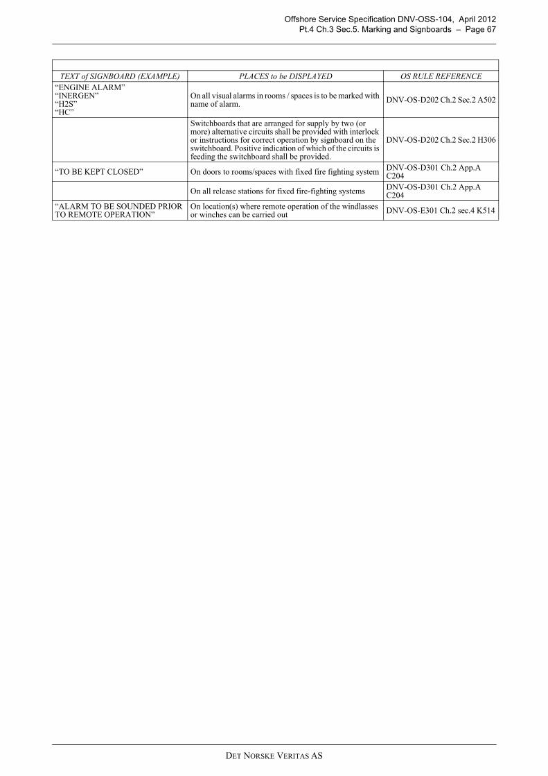
Offshore Service Specification DNV-OSS-104, April 2012Pt.4 Ch.3 Sec.5. Marking and Signboards – Page 67
“ENGINE ALARM”“INERGEN”“H2S”“HC”
On all visual alarms in rooms / spaces is to be marked with name of alarm. DNV-OS-D202 Ch.2 Sec.2 A502
Switchboards that are arranged for supply by two (or more) alternative circuits shall be provided with interlock or instructions for correct operation by signboard on the switchboard. Positive indication of which of the circuits is feeding the switchboard shall be provided.
DNV-OS-D202 Ch.2 Sec.2 H306
“TO BE KEPT CLOSED” On doors to rooms/spaces with fixed fire fighting system DNV-OS-D301 Ch.2 App.A C204
On all release stations for fixed fire-fighting systems DNV-OS-D301 Ch.2 App.A C204
“ALARM TO BE SOUNDED PRIOR TO REMOTE OPERATION”
On location(s) where remote operation of the windlasses or winches can be carried out DNV-OS-E301 Ch.2 sec.4 K514
TEXT of SIGNBOARD (EXAMPLE) PLACES to be DISPLAYED OS RULE REFERENCE
DET NORSKE VERITAS AS

Offshore Service Specification DNV-OSS-104, April 2012Pt.4 Ch.4 Sec.1. General – Page 68
CHAPTER 4 CONTROL AND COMMUNICATION SYSTEMS
Section 1. General
1.1 IntroductionThis chapter list requirements for control and telecommunication systems.The table below lists references required for a complete understanding of this chapter.
1.2 ApplicationThe requirements in this system are in special applicable for the fire & gas system, platform automation andGA/PA system. In this respect, the suppliers of these systems should take special notice of these during theirsystem design, delivery and installation on board. Requirements applicable only for units with the voluntary class notation ES, are identified by the notationname in bold in the head- and closing line.
1.3 Plans and data to be submittedA general overview of the required plans and analyses to be submitted is listed below. A more detailedoverviewed, tuned to the specific design and project scope can be obtained from DNV’s Nauticus ProductionSystem.
Section 2. PrinciplesThe principles for automation, safety and telecommunication systems are described in DNV-OS-D202 asfurther outlined in the remaining of this chapter.The definitions of safety and important systems together with the different levels of system availability as givenin Pt.1, Ch.4 are applicable for the automation system controlling these systems as well.
2.1 Response to failures
2.1.1 Failure detectionEssential and important systems shall have facilities to detect the most probable failures that may cause reducedor erroneous system performance.Failures detected shall initiate alarms in an assigned manned control station.The failure detection facilities shall at least, but not limited to, cover the following failure types:
— power failures— sensor and actuator failures.
Table 1-1 Overview of referencesReference Title
IMO Res. A.830(19) Code on Alarms and Indicators, 1995DNV-OS-A101 Safety Principles and ArrangementsDNV-OS-D202 Automation, Safety, and Telecommunication Systems
Table 1-2 Documentation requirements
Object Documentation type Additional description For approval (AP) orFor information (FI)
On request (R) Two-way voice internal communication systems
E170 - Electrical schematic drawing
Cable diagram and power supply arrangement.
AP
E030 - Arrangement plan Location of communication apparatuses. AP
Vessel control and monitoring systems
Z140 - Test procedure for quay and sea trial
AP
Engineer's alarm system
I200 - Control and monitoring system documentation
Integrated control and monitoring system
I010 - Control system philosophy
Emergency shut down system
I200 - Control and monitoring system documentation
DET NORSKE VERITAS AS

Offshore Service Specification DNV-OSS-104, April 2012Pt.4 Ch.4 Sec.3. System Design – Page 69
and additionally for computer based systems:
— communication errors— computer hardware failures— software execution failures— software logical failures.
2.1.2 Fail-safe functionality
The most probable failures, for example loss of power or wire failure, shall result in the least critical of anypossible new conditions.
Section 3. System DesignThe safety and automation system shall be designed as mutually independent systems. The different elementsmust not be designed as one combined system, where safety functions are combined with automation functions.
For essential and important systems, deviations between a command action and expected result of thecommand action shall initiate an alarm.
Planning and reporting system elements shall have no outputs for real-time process equipment control duringplanning mode.
Output from calculation, simulation or decision support modules shall not suppress basic information necessaryto allow safe operation of essential and important functions.
Other detailed requirements are given in OS-D202, Ch.2, Sec.2 as listed in the table below.
3.1 Additional requirements for computer based systems
For system design based on computers, additional requirements as given in D202, Ch.2, Sec.3 apply as detailedin the table below.
Section 4. Component Design and InstallationFor the design of components and installed typically under responsibility from the yard, the specificrequirements in D202, Ch.2, Sec.4 apply as detailed in the table below.
Section 5. User InterfaceThe location and design of the user interface shall give consideration to the physical capabilities of the user andcomply with accepted ergonomic principles. This requirement affects workstation design and arrangement,user input devices and displays/ screens. Detailed requirements are given in D202, Ch.2, Sec.5 as detailed in
Table 3-1 Description Reference in OS-D202, Ch.2, Sec.2
Automation system Sec.2, A200Safety system Sec.2, A400Alarms Sec.2, A600Indications Sec.2, A700System operation and maintenance Sec.2, B100
Table 3-2 Description References in D202, Ch.2, Sec.3
General requirements Sec.3 ASystem software Sec.3 BNetwork systems and communication Sec.3 C
Table 4-1 Description Reference in D202, Ch.2, Sec.4
General Sec.4 AEnvironmental conditions Sec.4 BElectrical and electronic equipment Sec.4 CPneumatic and Hydraulic equipment Sec.4 D
DET NORSKE VERITAS AS

Offshore Service Specification DNV-OSS-104, April 2012Pt.4 Ch.4 Sec.6. Emergency Control – Page 70
the table below.
Section 6. Emergency Control
6.1 Emergency shut downAn Emergency Shutdown System in compliance with MODU code 2009 regulation 6.5 shall be provided. AMobile Offshore Unit Safety Certificate is issued by an Administration or authorized organization other thanDNV is accepted as evidence.
6.1.1 Additional requirements for notation ESAn emergency shutdown system (ESD) shall include:
— manual input devices (push buttons)— interfaces towards other safety systems, as e.g.:
— fire detection system— gas detection system— alarm and communication systems— process shutdown system— drilling and well control system— firefighting systems— ventilation systems.
— a central control unit receiving and evaluating signals from the manual input devices and the interfacedsystems, and creating output signals to devices that shall be shut down or activated. The ESD central shallinclude a device providing visual indication of initiated inputs and activated outputs and a local audiblealarm
— output actuators as e.g. relays, valves and dampers, including status indicators— signal transfer lines between the ESD central and all input devices, interfaced systems and output actuators— power supply.
The ESD system shall
a) be designed so that the risk of unintentional shutdown caused by malfunction or inadvertent operation isminimised.
b) be designed to allow testing without interrupting other systems onboard.c) have continuous availability R0 as defined in DNV-OS-D202, Ch.2 Sec.1 B200.d) be located in a non-hazardous and continuously manned area.
The ESD central control unit shall be powered from the main power system and from a monitoredUninterruptible Power Supply (UPS) capable of at least 30 minutes continuous operation on loss of mainpower. The UPS shall be powered from both the main and the emergency power system (ref OS-A101 Ch.2,Sec.5 A).International requirements for a simplified shutdown hierarchy may be applied on agreement between yard andowner (ref OS-A101 Ch.2, Sec.8 E101).Additional requirements for ESD systems are given in OS-A101, Sec.5 as detailed in the table below.
Table 5-1 Description References in D202, Ch.2, Sec.5
Workstation design and arrangement Sec.5 BUser Input Device and Visual Display Unit Design Sec.5 CScreen based systems Sec.5 D
Table 6-1 Description References in OS-A101, Sec.5
Safety and shutdown philosophy Sec.5 BFail-safe functionality Sec.5 CProtection system and shutdown logic Sec.5 DAutomatic and manual shutdown Sec.5 ECertification of electrical equipment for use in an Emergency
Sec.5 F
DET NORSKE VERITAS AS
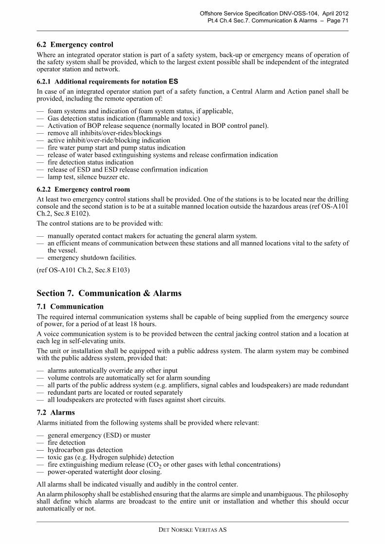
Offshore Service Specification DNV-OSS-104, April 2012Pt.4 Ch.4 Sec.7. Communication & Alarms – Page 71
6.2 Emergency controlWhere an integrated operator station is part of a safety system, back-up or emergency means of operation ofthe safety system shall be provided, which to the largest extent possible shall be independent of the integratedoperator station and network.
6.2.1 Additional requirements for notation ESIn case of an integrated operator station part of a safety function, a Central Alarm and Action panel shall beprovided, including the remote operation of:
— foam systems and indication of foam system status, if applicable,— Gas detection status indication (flammable and toxic)— Activation of BOP release sequence (normally located in BOP control panel).— remove all inhibits/over-rides/blockings — active inhibit/over-ride/blocking indication — fire water pump start and pump status indication — release of water based extinguishing systems and release confirmation indication — fire detection status indication — release of ESD and ESD release confirmation indication — lamp test, silence buzzer etc.
6.2.2 Emergency control room
At least two emergency control stations shall be provided. One of the stations is to be located near the drillingconsole and the second station is to be at a suitable manned location outside the hazardous areas (ref OS-A101Ch.2, Sec.8 E102).
The control stations are to be provided with:
— manually operated contact makers for actuating the general alarm system.— an efficient means of communication between these stations and all manned locations vital to the safety of
the vessel.— emergency shutdown facilities.
(ref OS-A101 Ch.2, Sec.8 E103)
Section 7. Communication & Alarms
7.1 CommunicationThe required internal communication systems shall be capable of being supplied from the emergency sourceof power, for a period of at least 18 hours.
A voice communication system is to be provided between the central jacking control station and a location ateach leg in self-elevating units.
The unit or installation shall be equipped with a public address system. The alarm system may be combinedwith the public address system, provided that:
— alarms automatically override any other input— volume controls are automatically set for alarm sounding— all parts of the public address system (e.g. amplifiers, signal cables and loudspeakers) are made redundant— redundant parts are located or routed separately— all loudspeakers are protected with fuses against short circuits.
7.2 AlarmsAlarms initiated from the following systems shall be provided where relevant:
— general emergency (ESD) or muster— fire detection— hydrocarbon gas detection— toxic gas (e.g. Hydrogen sulphide) detection— fire extinguishing medium release (CO2 or other gases with lethal concentrations)— power-operated watertight door closing.
All alarms shall be indicated visually and audibly in the control center.
An alarm philosophy shall be established ensuring that the alarms are simple and unambiguous. The philosophyshall define which alarms are broadcast to the entire unit or installation and whether this should occurautomatically or not.
DET NORSKE VERITAS AS
Offshore Service Specification DNV-OSS-104, April 2012Pt.4 Ch.4 Sec.7. Communication & Alarms – Page 72
The number of alarms during abnormal conditions shall be assessed and reduced as far as practicable by alarmprocessing/suppression techniques in order to have operator attention on the most critical alarms that requireoperator action.The alarms shall be clearly audible at all locations on the unit or installation, and shall be easily distinguishable.If noise in an area prevents the audible alarm being heard a visible means of alarm shall be provided.
Guidance note:See IMO Resolution A.830(19) Code on Alarms and Indicators, 1995 for details on priorities, grouping, locations andtypes, including colours, symbols etc.National authorities may have specific requirements deviating from the IMO Resolution. These will normally beacceptable for classification purposes.
---e-n-d---of---G-u-i-d-a-n-c-e---n-o-t-e---
Alarm to areas which are not regularly manned (e.g. cofferdams, tanks) may be covered by proceduralprecautions, e.g. using portable radios.Activation of the general alarm shall be possible from the main control stations, including navigation bridgeand radio room.Requirements for alarms in connection with watertight doors and release of hazardous fire extinguishingmedium are given in DNV-OS-C301 and DNV-OS-D301.The alarm system shall be regularly tested.
7.2.1 Additional requirements for notation ESThe two way voice communication extensions at control stations and the navigation bridge shall have priority.The two-way voice communication system shall be supplied by a battery or an uninterruptible power supply asa stand-by power supply sufficient to operate the system for at least 30 minutes.In addition to the alarm systems, a two-way communication system shall be provided for transmittal of alarm,instructions and information between those who may require them.The alarm and communication system shall be powered from the main power system and from a monitoredUninterruptible Power Supply (UPS) capable of at least 1 (one) hour continuous operation on loss of mainpower. The UPS shall be powered from both the main and the emergency power system.
DET NORSKE VERITAS AS

Offshore Service Specification DNV-OSS-104, April 2012Pt.4 Ch.5 Sec.1. General – Page 73
CHAPTER 5 FIRE PROTECTION
Section 1. General
1.1 IntroductionThis chapter provides principles for design, construction and installation of fire protection of offshore units andinstallations.
The table below lists references required for a complete understanding of this chapter.
1.2 ApplicationA Mobile Offshore Unit Safety Certificate is issued by an Administration or authorized organization other thanDNV is accepted as evidence that the unit is in accordance with the requirements of this Chapter.
Where the Administration has authorized DNV to issue the MOU safety certificates on its behalf, DNV willgive effect to the fire protection, detection and extinction requirements following the descriptions of thischapter.
Requirements applicable only for units with the voluntary class notation ES are identified by the notation namein bold in the head- and closing line.
1.3 Plans and data to be submittedA general overview of the required plans and analyses to be submitted is listed below. A more detailedoverviewed, tuned to the specific design and project scope can be obtained from DNV’s Nauticus ProductionSystem.
Table 1-1 Reference Title
IMO MODU Code Code for the construction and equipment of Mobile Offshore Drilling Units, 2009IMO FSS Code International Code for Fire Safety SystemsDNV-OS-A101 Safety Principles and ArrangementsDNV-OS-D101 Marine and Machinery Systems and EquipmentDNV-OS-D202 Automation, Safety, and Telecommunication SystemsDNV-OS-D301 Fire protection
Table 1-2 Documentation requirements
Object Documentation type Additional description For approval (AP) orFor information (FI)
On request (R)
Fire resisting and non-combustible materials
M020- Material specification, fire related properties
Surface materials, insulation materials, primary deck coverings, textiles, furniture and bedding.
AP
Structural fire protection arrangements
G060 - Structural fire protection drawing AP
V060 - Penetration drawings AP
Machinery space fire doors M020- Material specification, fire related properties AP
Structural fire protection of drilling area structure Z110 - Data sheet AP
Fire and gas detection and alarm systems
Cause and effect diagram APDesign philosophy AP
Fire detection and alarm systemI200 - Control and monitoring system documentation AP
Z030 - System arrangement plan AP
Hydrocarbon gas detection and alarm system, fixed
I200 - Control and monitoring system documentation AP
Z030 - System arrangement plan Detectors, call points and alarm devices. AP
Fire water systemS010 - Piping diagram APS030 - Capacity analysis APZ030 - System arrangement plan AP
DET NORSKE VERITAS AS

Offshore Service Specification DNV-OSS-104, April 2012Pt.4 Ch.5 Sec.2. Principles – Page 74
Section 2. PrinciplesRequirements for fire protection are given in DNV-OS-D301 (principles, technical requirements and guidancefor design, manufacturing and installation). This standard meets and is based on the regulations of the MODUcode 2009. Wherever, the MODU code requires leaves room for interpretation, the standard completes theCode with additional specific requirements.
Section 3. Passive Fire ProtectionPassive fire protection is as required by MODU code 9.2, Structural fire protection. Specific requirements formachinery systems and equipment are given is OS-D101, Ch.2, Sec.1, A500. Fire protection measures forcables are given in OS-D101 Ch.2, Sec.10 C400.
Openings and penetrations in fire rated divisions shall be arranged so as to maintain the fire rating of thedivisions. Penetrations shall be approved for the actual divisions where they are to be installed.
Openings in bulkheads of “H” class are in general to be avoided.
3.1 Additional requirements for notation ESEquipment and systems which are important to safety and need to be kept intact during a fire, shall be providedwith passive fire protection or located such that they will not be exposed to excessive fire loads.
Guidance note:Such equipment and systems could be valves and their accumulators, cables and their trays, piping systems andpressure vessels with their support, position mooring system etc.
---e-n-d---of---G-u-i-d-a-n-c-e---n-o-t-e---
Section 4. Fire Fighting Systems
4.1 Fire pumps, fire mains, hydrants and hosesMODU code 2009 Ch.9, Sec.7 applies for fire pumps, fire mains, hydrant and hoses with the following remarks:
— It is acceptable that the fire water system is supplied from a header supplied from a leg well suction rawwater system.
— If installed, the lowest water level to assure supply of water from each of any two fire hydrants, hoses and19 mm nozzles while maintaining a minimum pressure of 0.35 N/mm2 at any hydrant for 15 minutes.Minimum tank capacity (below lowest automatically maintained water level) shall be 10 m3. Minimum oneof the raw water pumps are to be arranged for automatic operation.
Guidance note:Minimum tank capacity to be compatible to fire water supply for all fire pump running modes as e.g. start-up in casethe dimensional fire scenario.
---e-n-d---of---G-u-i-d-a-n-c-e---n-o-t-e---
— In interpretation of MODU code 9.7.17, use of GRE/GRP material in firewater ring main, we refer DNVOS-D101 Ch.2 Sec.2 B505
Machinery spaces fixed water spraying fire extinguishing system
G200 - Fixed fire extinguishing system documentation APDrilling area water spraying fire
extinguishing systemExternal surface protection water spraying system
Emergency escape G100 – Escape and evacuation study AP
Assembly station / muster station / temporary refuge space Z030 – System Arrangement plan AP
Escape route G120 – Escape route drawing AP
Table 1-2 Documentation requirements (Continued)
Object Documentation type Additional description For approval (AP) orFor information (FI)
On request (R)
DET NORSKE VERITAS AS
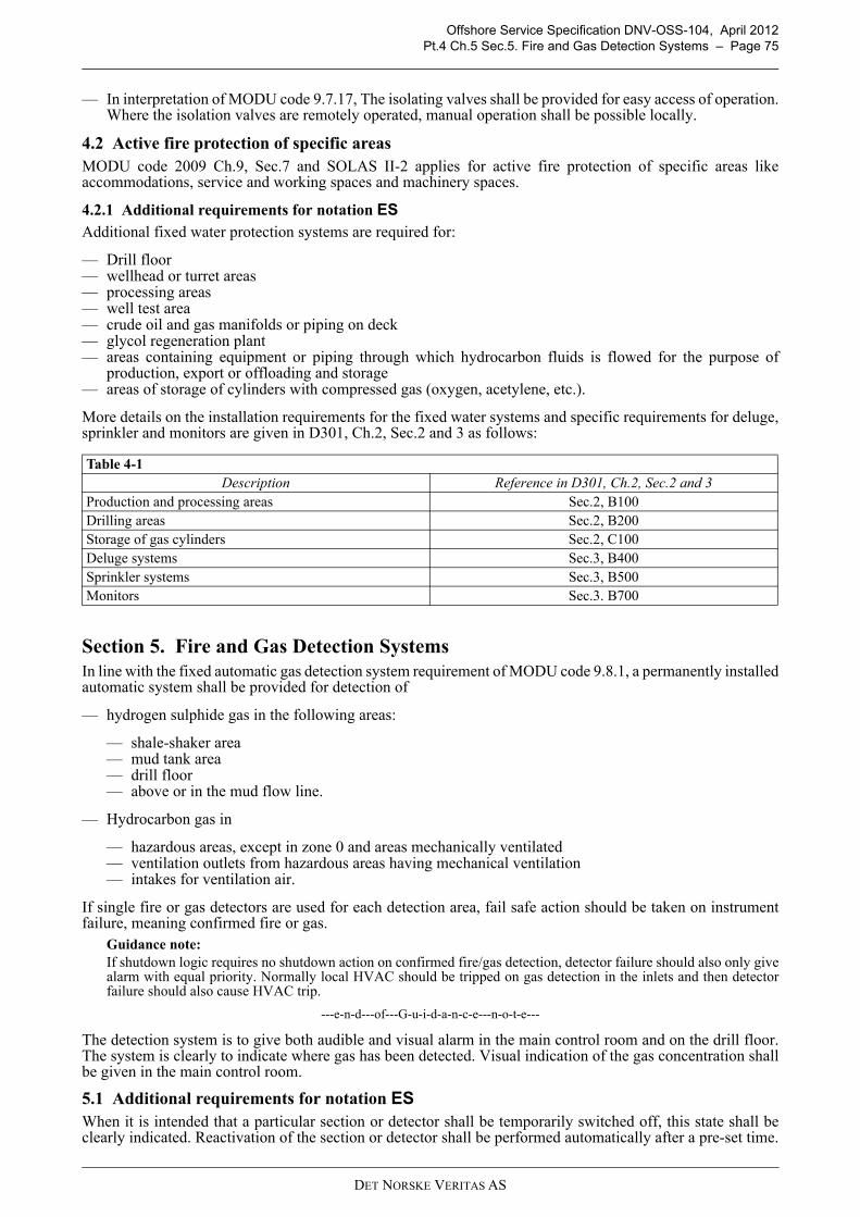
Offshore Service Specification DNV-OSS-104, April 2012Pt.4 Ch.5 Sec.5. Fire and Gas Detection Systems – Page 75
— In interpretation of MODU code 9.7.17, The isolating valves shall be provided for easy access of operation.Where the isolation valves are remotely operated, manual operation shall be possible locally.
4.2 Active fire protection of specific areasMODU code 2009 Ch.9, Sec.7 and SOLAS II-2 applies for active fire protection of specific areas likeaccommodations, service and working spaces and machinery spaces.
4.2.1 Additional requirements for notation ESAdditional fixed water protection systems are required for:
— Drill floor— wellhead or turret areas— processing areas— well test area— crude oil and gas manifolds or piping on deck— glycol regeneration plant— areas containing equipment or piping through which hydrocarbon fluids is flowed for the purpose of
production, export or offloading and storage— areas of storage of cylinders with compressed gas (oxygen, acetylene, etc.).
More details on the installation requirements for the fixed water systems and specific requirements for deluge,sprinkler and monitors are given in D301, Ch.2, Sec.2 and 3 as follows:
Section 5. Fire and Gas Detection SystemsIn line with the fixed automatic gas detection system requirement of MODU code 9.8.1, a permanently installedautomatic system shall be provided for detection of
— hydrogen sulphide gas in the following areas:
— shale-shaker area— mud tank area— drill floor— above or in the mud flow line.
— Hydrocarbon gas in
— hazardous areas, except in zone 0 and areas mechanically ventilated— ventilation outlets from hazardous areas having mechanical ventilation— intakes for ventilation air.
If single fire or gas detectors are used for each detection area, fail safe action should be taken on instrumentfailure, meaning confirmed fire or gas.
Guidance note:If shutdown logic requires no shutdown action on confirmed fire/gas detection, detector failure should also only givealarm with equal priority. Normally local HVAC should be tripped on gas detection in the inlets and then detectorfailure should also cause HVAC trip.
---e-n-d---of---G-u-i-d-a-n-c-e---n-o-t-e---
The detection system is to give both audible and visual alarm in the main control room and on the drill floor.The system is clearly to indicate where gas has been detected. Visual indication of the gas concentration shallbe given in the main control room.
5.1 Additional requirements for notation ESWhen it is intended that a particular section or detector shall be temporarily switched off, this state shall beclearly indicated. Reactivation of the section or detector shall be performed automatically after a pre-set time.
Table 4-1 Description Reference in D301, Ch.2, Sec.2 and 3
Production and processing areas Sec.2, B100Drilling areas Sec.2, B200Storage of gas cylinders Sec.2, C100Deluge systems Sec.3, B400Sprinkler systems Sec.3, B500Monitors Sec.3. B700
DET NORSKE VERITAS AS
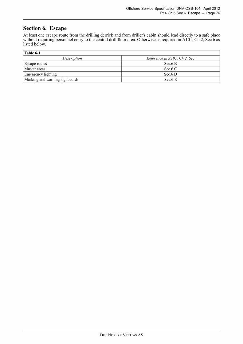
Offshore Service Specification DNV-OSS-104, April 2012Pt.4 Ch.5 Sec.6. Escape – Page 76
Section 6. EscapeAt least one escape route from the drilling derrick and from driller's cabin should lead directly to a safe placewithout requiring personnel entry to the central drill floor area. Otherwise as required in A101, Ch.2, Sec 6 aslisted below.
Table 6-1 Description Reference in A101, Ch.2, Sec
Escape routes Sec.6 BMuster areas Sec.6 CEmergency lighting Sec.6 DMarking and warning signboards Sec.6 E
DET NORSKE VERITAS AS

Offshore Service Specification DNV-OSS-104, April 2012Pt.4 Ch.6 Sec.1. Introduction – Page 77
CHAPTER 6 ENHANCED CONTROL & SAFETY SYSTEMS
Section 1. Introduction
1.1 GeneralThis chapter summarizes the specific requirements for the Enhanced Control & Safety Systems (ES) notationas identified in the previous chapters.
1.2 ObjectiveThe objective of the ES notation is to increase safety over MODU Code and main class safety level in a costeffective way.
1.3 ScopeES covers requirements for machinery and systems, in special regarding control systems and fire safety.All of the technical requirements as listed in this chapter come in addition to MODU Code 2009 and main classrequirements as described in the remaining of this rule book.
1.4 Documentation requirementsTo verify compliance with the requirements for enhanced safety, the following additional documentations isrequired.
Section 2. Control Systems
2.1 Emergency shutdownAn emergency shutdown system (ESD) shall include:
— manual input devices (push buttons)— interfaces towards other safety systems, as e.g.:
— fire detection system— gas detection system— alarm and communication systems— process shutdown system— drilling and well control system— fire fighting systems— ventilation systems
— a central control unit receiving and evaluating signals from the manual input devices and the interfacedsystems, and creating output signals to devices that shall be shut down or activated. The ESD central shallinclude a device providing visual indication of initiated inputs and activated outputs and a local audiblealarm
— output actuators as e.g. relays, valves and dampers, including status indicators— signal transfer lines between the ESD central and all input devices, interfaced systems and output actuators— power supply.
The ESD system shall
a) be designed so that the risk of unintentional shutdown caused by malfunction or inadvertent operation isminimized.
b) be designed to allow testing without interrupting other systems onboard.c) have continuous availability R0 as defined in DNV-OS-D202, Ch.2 Sec.1 B200.d) be located in a non-hazardous and continuously manned area.
The ESD central control unit shall be powered from the main power system and from a monitoredUninterruptible Power Supply (UPS) capable of at least 30 minutes continuous operation on loss of mainpower. The UPS shall be powered from both the main and the emergency power system (ref OS-A101 Ch.2,Sec.5 A).International requirements for a simplified shutdown hierarchy may be applied on agreement between yard and
813 Emergency shut down system RC G130 Cause and effect diagram Y; AP 1A1 G1 RC Z050 Design philosophy Y; AP 1A1 G1 RC
DET NORSKE VERITAS AS
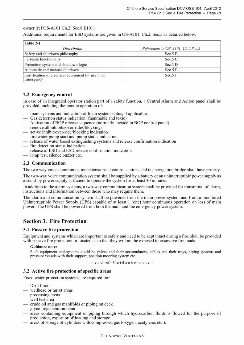
Offshore Service Specification DNV-OSS-104, April 2012Pt.4 Ch.6 Sec.3. Fire Protection – Page 78
owner (ref OS-A101 Ch.2, Sec.8 E101).
Additional requirements for ESD systems are given in OS-A101, Ch.2, Sec.5 as detailed below.
2.2 Emergency controlIn case of an integrated operator station part of a safety function, a Central Alarm and Action panel shall beprovided, including the remote operation of:
— foam systems and indication of foam system status, if applicable,— Gas detection status indication (flammable and toxic)— Activation of BOP release sequence (normally located in BOP control panel).— remove all inhibits/over-rides/blockings — active inhibit/over-ride/blocking indication — fire water pump start and pump status indication — release of water based extinguishing systems and release confirmation indication — fire detection status indication — release of ESD and ESD release confirmation indication — lamp test, silence buzzer etc.
2.3 CommunicationThe two way voice communication extensions at control stations and the navigation bridge shall have priority.
The two-way voice communication system shall be supplied by a battery or an uninterruptible power supply asa stand-by power supply sufficient to operate the system for at least 30 minutes.
In addition to the alarm systems, a two-way communication system shall be provided for transmittal of alarm,instructions and information between those who may require them.
The alarm and communication system shall be powered from the main power system and from a monitoredUninterruptible Power Supply (UPS) capable of at least 1 (one) hour continuous operation on loss of mainpower. The UPS shall be powered from both the main and the emergency power system.
Section 3. Fire Protection
3.1 Passive fire protectionEquipment and systems which are important to safety and need to be kept intact during a fire, shall be providedwith passive fire protection or located such that they will not be exposed to excessive fire loads.
Guidance note:Such equipment and systems could be valves and their accumulators, cables and their trays, piping systems andpressure vessels with their support, position mooring system etc.
---e-n-d---of---G-u-i-d-a-n-c-e---n-o-t-e---
3.2 Active fire protection of specific areasFixed water protection systems are required for:
— Drill floor— wellhead or turret areas— processing areas— well test area— crude oil and gas manifolds or piping on deck— glycol regeneration plant— areas containing equipment or piping through which hydrocarbon fluids is flowed for the purpose of
production, export or offloading and storage— areas of storage of cylinders with compressed gas (oxygen, acetylene, etc.).
Table 2-1 Description References in OS-A101, Ch.2 Sec.5
Safety and shutdown philosophy Sec.5 BFail-safe functionality Sec.5 CProtection system and shutdown logic Sec.5 DAutomatic and manual shutdown Sec.5 ECertification of electrical equipment for use in an Emergency
Sec.5 F
DET NORSKE VERITAS AS
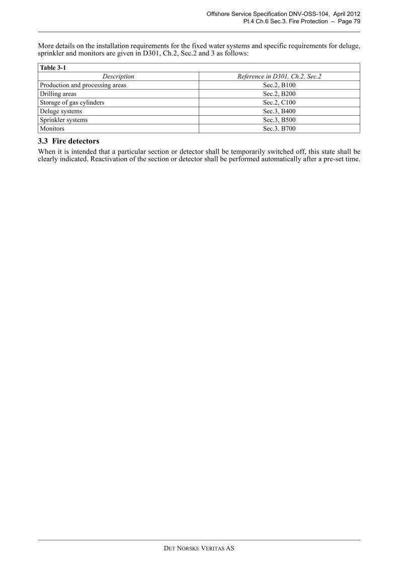
Offshore Service Specification DNV-OSS-104, April 2012Pt.4 Ch.6 Sec.3. Fire Protection – Page 79
More details on the installation requirements for the fixed water systems and specific requirements for deluge,sprinkler and monitors are given in D301, Ch.2, Sec.2 and 3 as follows:
3.3 Fire detectorsWhen it is intended that a particular section or detector shall be temporarily switched off, this state shall beclearly indicated. Reactivation of the section or detector shall be performed automatically after a pre-set time.
Table 3-1 Description Reference in D301, Ch.2, Sec.2
Production and processing areas Sec.2, B100Drilling areas Sec.2, B200Storage of gas cylinders Sec.2, C100Deluge systems Sec.3, B400Sprinkler systems Sec.3, B500Monitors Sec.3. B700
DET NORSKE VERITAS AS

Offshore Service Specification DNV-OSS-104, April 2012Page 80
PART 5 – CERTIFICATION
DET NORSKE VERITAS AS
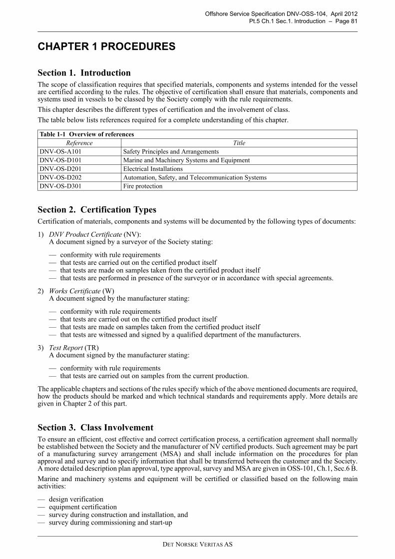
Offshore Service Specification DNV-OSS-104, April 2012Pt.5 Ch.1 Sec.1. Introduction – Page 81
CHAPTER 1 PROCEDURES
Section 1. IntroductionThe scope of classification requires that specified materials, components and systems intended for the vesselare certified according to the rules. The objective of certification shall ensure that materials, components andsystems used in vessels to be classed by the Society comply with the rule requirements.
This chapter describes the different types of certification and the involvement of class.
The table below lists references required for a complete understanding of this chapter.
Section 2. Certification TypesCertification of materials, components and systems will be documented by the following types of documents:
1) DNV Product Certificate (NV):A document signed by a surveyor of the Society stating:
— conformity with rule requirements — that tests are carried out on the certified product itself — that tests are made on samples taken from the certified product itself — that tests are performed in presence of the surveyor or in accordance with special agreements.
2) Works Certificate (W)A document signed by the manufacturer stating:
— conformity with rule requirements — that tests are carried out on the certified product itself — that tests are made on samples taken from the certified product itself — that tests are witnessed and signed by a qualified department of the manufacturers.
3) Test Report (TR)A document signed by the manufacturer stating:
— conformity with rule requirements — that tests are carried out on samples from the current production.
The applicable chapters and sections of the rules specify which of the above mentioned documents are required,how the products should be marked and which technical standards and requirements apply. More details aregiven in Chapter 2 of this part.
Section 3. Class InvolvementTo ensure an efficient, cost effective and correct certification process, a certification agreement shall normallybe established between the Society and the manufacturer of NV certified products. Such agreement may be partof a manufacturing survey arrangement (MSA) and shall include information on the procedures for planapproval and survey and to specify information that shall be transferred between the customer and the Society.A more detailed description plan approval, type approval, survey and MSA are given in OSS-101, Ch.1, Sec.6 B.
Marine and machinery systems and equipment will be certified or classified based on the following mainactivities:
— design verification — equipment certification — survey during construction and installation, and — survey during commissioning and start-up
Table 1-1 Overview of referencesReference Title
DNV-OS-A101 Safety Principles and ArrangementsDNV-OS-D101 Marine and Machinery Systems and EquipmentDNV-OS-D201 Electrical InstallationsDNV-OS-D202 Automation, Safety, and Telecommunication SystemsDNV-OS-D301 Fire protection
DET NORSKE VERITAS AS

Offshore Service Specification DNV-OSS-104, April 2012Pt.5 Ch.2 Sec.1. General – Page 82
CHAPTER 2 MACHINERY AND SYSTEM CERTIFICATION
Section 1. GeneralThis chapter gives an overview of the certification requirements for machinery and systems.
Section 2. PrinciplesEquipment shall be certified consistent with its functions and importance for safety. Equipment for non-essential systems does not need to be certified but is to be delivered with documentation as for equipment Cat.II.
Equipment referred to in this standard will be categorized as follows:
Category I equipment related to safety for which a DNV certificate is required.Category II equipment related to safety for which a works certificate prepared by the manufacturer is accepted.
The extent of required survey by DNV is to be decided on the basis of manufacturer's QA/QC system,manufacturing survey arrangement (MSA) with DNV and type of fabrication methods.
Guidance note:It should be noted that the scopes defined for category IA and IB are typical and adjustments may be required basedon considerations such as:
- standard type approved products / MSA agreement- complexity and size of a delivery- previous experience with equipment type- maturity and effectiveness of manufacturer's quality assurance system- degree of subcontracting.
---e-n-d---of---G-u-i-d-a-n-c-e---n-o-t-e---
Equipment of category II is normally accepted on the basis of a works certificate prepared by the manufacturer.The certificate shall contain the following data as a minimum:
1) equipment specification or data sheet
2) limitations with respect to operation of equipment
3) statement (affidavit) from the manufacturer to confirm that the equipment has been constructed,manufactured and tested according to the recognized methods, codes and standards. Test report to beincluded in work certificates for diesel engines.
4) A test repost (TR) may be issued based on testing carried out on samples from the current production ofequal products.
Guidance note:Independent test certificate or report for the equipment or approval certificate for manufacturing system may also beaccepted.
---e-n-d---of---G-u-i-d-a-n-c-e---n-o-t-e---
Section 3. Machinery Systems and EquipmentPiping and piping components are to be delivered with material certification in accordance with Table 3-1.
Table 2-1 Cat 1A Cat 1B Cat 1C Cat 2A Cat 2B
Scope D S2 R2
D S1 R2 S1 R2 R2 R1
Certificate / Document NV NV NV W TR
D: Design reviewS1: Witness of final testing of completed productS2: Survey during construction and witness of final testing of completed productR1: Review of manufacturers documentation (typical for product)R2: Review of manufacturers documentation (specific to product)
DET NORSKE VERITAS AS

Offshore Service Specification DNV-OSS-104, April 2012Pt.5 Ch.2 Sec.3. Machinery Systems and Equipment – Page 83
Where the requirement calls for witness by 3rd party (Certificate Type 3.2) this shall be carried out by DNV.
3.1 Miscellaneous mechanical componentsCertification requirement for miscellaneous machinery mechanical components are given in the table below.
Table 3-1 Component Material Class of
piping system
Nominal diameter
(mm)
Design temperature
(°C)
Type of documentation 3.2 certificate 3.1 certificate 2.2 report
Pipes 1) I > 50 xII, III > 50 xI, II, III ≤ 50 x
Flanges and bolts > 400 x≤ 400 x
Bodies of valves and fittings 1), source materials of steel expansion bellows, other pressure containing components not considered as pressure vessels
Steel I > 100 > 400 x≤ 100 > 400 x
Steel or nodular cast iron
I, II > 100 ≤ 400 x≤ 100 ≤ 400 x
III x Cast iron III x
Copper alloys
I, II > 50 x ≤ 50 x
III x
Pump housings I x II, III x
2.2 Test report: Confirmation by the manufacturer that the supplied products fulfill the purchase specification, and test data from regular production, not necessarily from products supplied 2.2 3.1 Inspection certificate (Works Certificate): Test results of all specified tests from samples taken from the products supplied. Inspection and tests witnessed and signed by QA department 3.1 3.2 Inspection certificate (Test Certificate): As work certificate, inspection and tests witnessed and signed by QA department and an independent third party body 1) Pipes and bodies of valves fitted on unit or installation's side and bottom and bodies of valves fitted on collision bulkhead shall be provided with documentation as required for class I piping systems. (Valves to hydraulic pressure tested in the presence of a DNV Surveyor)
Table 3-2 Item Certification category
Jacking machinery 1ABoiler 1ACondenser 2ABoiler heat exchanger 1APumps for boiler 1CBoiler PSV 1CBoiler spark arrestor 2BWinches 1AHydraulic Cylinders pD > 20000 1) 1AHydraulic Cylinders pD ≤ 20000 2ACompressor 2)
Hydraulic cylinders for cleating and manoeuvring of watertight doors and hatches shall be delivered with certificate of category 1A regardless of pressure and size. Cleating cylinders where the locking mechanism is placed inside the cylinder are to be type approved.Compressors to be certified in accordance with Ship Rules Pt.4 Ch.5 Sec.4.p = design pressure (bar)D = internal diameter of cylinder tube (mm)
DET NORSKE VERITAS AS

Offshore Service Specification DNV-OSS-104, April 2012Pt.5 Ch.2 Sec.3. Machinery Systems and Equipment – Page 84
3.2 Pressure vessels Certification requirement for pressure vessels are given in the table below.
3.3 Main power, emergency power, fire water pumps Certification requirements for main power, emergency power and fire water pumps is given in the table below.
Requirements for certification and testing are described in DNV Ship Rules, Pt.4, Ch.3, Sec.1 as detailed in thetable below.
Table 3-3
Property ConditionsCategory
I 2) II
Pressure
X
X
Vacuum or external pressure X
Medium
Steam XToxic fluid XThermal oil XLiquids with flash point below 100°C XFlammable fluids with T > 150°C XOther fluids with T > 220°C XCompressed air/gas PV ≥ 1.5 X
Materialσy 345 MPa (50000 psi) or σt 515 MPa (75000 psi) XWhere impact testing is required. X
Free standing structural storage tanks will be specially considered based on stored medium, volume and height. These may be designed according to the requirements of DNV-OS-C101.Normally category IA, however, limited class survey may be agreed upon with DNV based on manufacturer's QA/QC system, manufacturing survey arrangement (MSA) and fabrication methods.
P = internal design pressure in barDi = inside diameter in mmV = volume in m3
T = design temperatureσy = specified yield strengthσt = specified ultimate tensile strength
Table 3-4 Component Category
Engines for main power, emergency power and auxiliary power 1AThe individual components within the equipment train and other auxiliary systems are to be certified as required elsewhere in the rules, e.g. HVAC, and fire protection.
Table 3-5 Description Reference in DNV Ship Rules, Pt.4, Ch.3, Sec.1
Certification of parts Sec.1, C200Testing and inspection of parts Sec.1, C300Inspection during assembly Sec.1, C400Workshop Testing Sec.1 DShipboard Testing Sec.1 I
1 P20000
Di 1000+------------------------≤<
P20000
Di 1000+------------------------>
DET NORSKE VERITAS AS

Offshore Service Specification DNV-OSS-104, April 2012Pt.5 Ch.2 Sec.4. Electrical Installations – Page 85
3.4 Components in marine piping systemsCertification requirements for components in marine piping system is given in the table below.
Section 4. Electrical Installations
4.1 Required certificatesElectrical equipment serving essential or important functions and cables shall be delivered with certificates asrequired by Table 4-1. Additional requirements to certification may be given by other relevant parts of the DNVoffshore standards.Equipment covered by a valid type approval certificate is generally accepted without further designverification, unless otherwise stated in the certificate. A reference to the type approval certificate shallsubstitute the required documentation for DNV design assessment.A product certificate may be issued based on the type approval certificate and a product survey, unlessotherwise stated in the type approval certificate.
Table 3-6 Item Certification category
Piping system items for main and emergency powerFuel oil transfer pump 1CLube oil pump 1CCooling system pump unit 1CLube oil heat exchanger 1CFuel oil heat exchanger 1CValvesValves for sea inlet or discharge with DN >100 mm 1CValves with DN >100 mm and p>16 bar 1CNon-standard valves 1BCompressed air systemsStarting air compressors 1CPressure relief valves 2ABallast systemBallast pumps 1CBallast control system 1ABilge and drain systemBilge control system 2ABilge pumps 1CBilge ejectors 2AStrainers 2BStrums and rose boxes 2BAir and sounding systemsAir vent heads 1BTank level indicators 2ASounding control panel 1BStriking plates 2BSounding rods 2BLeak detection system 2BHydraulic control of safety critical valves etc.Hydraulic control panel 1BPumps in hydraulic control system 1CHydraulic power pack 2AAccumulators (pV > 150 kNm) 1BAccumulators (others) 2ATanks for hydraulic fluid 2B
DET NORSKE VERITAS AS
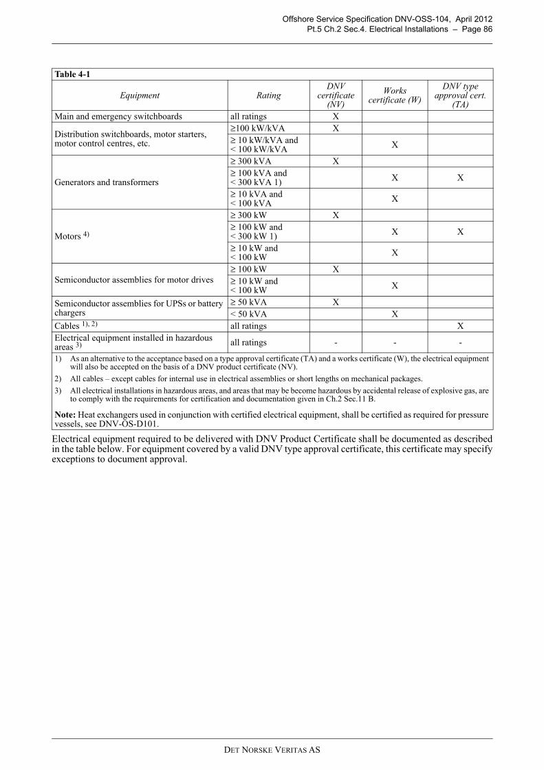
Offshore Service Specification DNV-OSS-104, April 2012Pt.5 Ch.2 Sec.4. Electrical Installations – Page 86
Electrical equipment required to be delivered with DNV Product Certificate shall be documented as describedin the table below. For equipment covered by a valid DNV type approval certificate, this certificate may specifyexceptions to document approval.
Table 4-1
Equipment RatingDNV
certificate (NV)
Works certificate (W)
DNV type approval cert.
(TA)Main and emergency switchboards all ratings X
Distribution switchboards, motor starters, motor control centres, etc.
≥100 kW/kVA X≥ 10 kW/kVA and < 100 kW/kVA X
Generators and transformers
≥ 300 kVA X≥ 100 kVA and < 300 kVA 1) X X
≥ 10 kVA and < 100 kVA X
Motors 4)
≥ 300 kW X≥ 100 kW and < 300 kW 1) X X
≥ 10 kW and < 100 kW X
Semiconductor assemblies for motor drives≥ 100 kW X≥ 10 kW and < 100 kW X
Semiconductor assemblies for UPSs or battery chargers
≥ 50 kVA X< 50 kVA X
Cables 1), 2) all ratings XElectrical equipment installed in hazardous areas 3) all ratings - - -
1) As an alternative to the acceptance based on a type approval certificate (TA) and a works certificate (W), the electrical equipment will also be accepted on the basis of a DNV product certificate (NV).
2) All cables – except cables for internal use in electrical assemblies or short lengths on mechanical packages.
3) All electrical installations in hazardous areas, and areas that may be become hazardous by accidental release of explosive gas, are to comply with the requirements for certification and documentation given in Ch.2 Sec.11 B.
Note: Heat exchangers used in conjunction with certified electrical equipment, shall be certified as required for pressure vessels, see DNV-OS-D101.
DET NORSKE VERITAS AS

Offshore Service Specification DNV-OSS-104, April 2012Pt.5 Ch.2 Sec.4. Electrical Installations – Page 87
Table 4-2 Documentation requirements
Object Documentation type Additional description For approval (AP) or For information (FI)
Cables E110 - Cable data sheet and design drawing
For cables not having a DNV type approval. AP
Electric propulsion motors Shafting documentation as required in Ch.4 Sec.1 A200
Shafting for electric propulsion motors in mechanical propulsion line.
AP
Shaft generators Shafting documentation as required in Ch.4 Sec.1 A200
Shafting for electric generators in mechanical propulsion line.
AP
Main and emergency switchboards
E120 - Electrical data sheet, general FI
E140 - Assembly schedules and technical data AP
E150 - Strength calculation with respect to short circuit
When designed sub-transient short circuit strength exceeds 50 kA r.m.s.
FI
E160 - Internal arc withstanding report
High voltage switchboards only. FI
E170 - Electrical schematic drawing AP
E180 - Layout of electrical assembly FI
E240 - Functional description for electrical assemblies
FI
Semi-conductor assemblies
E120 - Electrical data sheet, general AP
E130 - Electrical data sheet, semiconductor assemblies FI
E140 - Assembly schedules and technical data AP
E180 - Layout of electrical assembly FI
E240 - Functional description for electrical assemblies
FI
Z120 - Test procedure at manufacturer AP
Distribution switchboards, motor starters, motor control centres, harmonic filters etc.
E120 - Electrical data sheet, general AP
E140 - Assembly schedules and technical data AP
E150 - Strength calculation with respect to short circuit
When designed sub-transient short circuit strength exceeds 50 kA r.m.s.
FI
E160 - Internal arc withstanding report
High voltage switchboards only. FI
E170 - Electrical schematic drawing AP
E180 - Layout of electrical assembly FI
Systems for automatic start and stop of generator drivers and for automatic operation of breakers.
I020 - Control system functional description AP
I030 - Block diagram AP I050 - Power supply arrangement AP
I080 - Data sheet with environmental specifications
AP
Z120 - Test procedure at manufacturer AP
DET NORSKE VERITAS AS
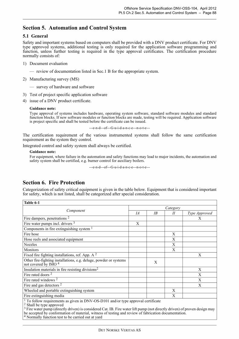
Offshore Service Specification DNV-OSS-104, April 2012Pt.5 Ch.2 Sec.5. Automation and Control System – Page 88
Section 5. Automation and Control System
5.1 GeneralSafety and important systems based on computers shall be provided with a DNV product certificate. For DNVtype approved systems, additional testing is only required for the application software programming andfunction, unless further testing is required in the type approval certificates. The certification procedurenormally consists of:
1) Document evaluation
— review of documentation listed in Sec.1 B for the appropriate system.
2) Manufacturing survey (MS)
— survey of hardware and software
3) Test of project specific application software
4) issue of a DNV product certificate.
Guidance note:Type approval of systems includes hardware, operating system software, standard software modules and standardfunction blocks. If new software modules or function blocks are made, testing will be required. Application softwareis project specific and shall be tested before the certificate can be issued.
---e-n-d---of---G-u-i-d-a-n-c-e---n-o-t-e---
The certification requirement of the various instrumented systems shall follow the same certificationrequirement as the system they control.
Integrated control and safety system shall always be certified.Guidance note:For equipment, where failure in the automation and safety functions may lead to major incidents, the automation andsafety system shall be certified, e.g. burner control for auxiliary boilers.
---e-n-d---of---G-u-i-d-a-n-c-e---n-o-t-e---
Section 6. Fire ProtectionCategorization of safety critical equipment is given in the table below. Equipment that is considered importantfor safety, which is not listed, shall be categorized after special consideration.
Table 6-1
ComponentCategory
IA IB II Type ApprovedFire dampers, penetrations 2 XFire water pumps incl. drivers 3 XComponents in fire extinguishing system 1
Fire hose XHose reels and associated equipment XNozzles XMonitors XFixed fire fighting installations, ref. App. A 2 XOther fire-fighting installations, e.g. deluge, powder or systems not covered by IMO 4 X
Insulation materials in fire resisting divisions2 XFire rated doors 2 XFire rated windows 2 XFire and gas detectors 2 XWheeled and portable extinguishing system XFire extinguishing media X1 To follow requirements as given in DNV-OS-D101 and/or type approval certificate2 Shall be type approved3 Fire water pump (directly driven) is considered Cat. IB. Fire water lift pump (not directly driven) of proven design may be accepted by conformation of material, witness of testing and review of fabrication documentation.4 Normally function test to be carried out at yard
DET NORSKE VERITAS AS

Offshore Service Specification DNV-OSS-104, April 2012Pt.5 Ch.2 Sec.7. Watertight/ Weathertight Integrity – Page 89
Section 7. Watertight/ Weathertight IntegrityCertification requirements for components related to water- and weathertight integrity as given in DNV-OS-C301, Ch.3, Sec.1, C200 are listed in the table below.
Table 7-1
ComponentCategory
IA IB IIWatertight doors and hatch covers xWeathertight doors and hatch covers1) xSide scuttles and windows xAutomatic closing devices for air pipes xValves for sea inlet or discharge xHydraulic system for watertight closing appliances xAccumulator, hand pumps xControl and monitoring systems for watertight closing appliances x1) In addition to the Work Certificate a design approval performed by DNV is required.
DET NORSKE VERITAS AS

Offshore Service Specification DNV-OSS-104, April 2012Page 90
PART 6 – NEWBUILDING SURVEY
DET NORSKE VERITAS AS

Offshore Service Specification DNV-OSS-104, April 2012Pt.6 Ch.1 Sec.1. Overview – Page 91
CHAPTER 1 INTRODUCTION
Section 1. Overview This part gives an overview of the class requirements as relevant for the building site.
Section 2. StructureAfter the principles given in this chapter, chapter 2 continues with the required survey planning defining theclass involvement on site in the remaining of the new building process. Chapter 3 thereafter describes classrequirements regarding fabrication and testing of the structure. Chapter 4 continuous with a detailed descriptionof the class related work process during mechanical completion, testing and commissioning. Chapter 5concludes with an overview of the deliverables from class after commissioning of the unit. The table below lists references required for a complete understanding of this chapter.
Section 3. PrinciplesBasis principles for the involvement of class during new building are given in OSS-101, Ch.1, Sec.4 A
Table 2-1 Overview of referencesReference Title
DNV-OSS-101 Rules for Classification of Offshore Drilling and Support UnitsDNV-OS-A101 Safety Principles and ArrangementsDNV-OS-C301 Stability and Watertight IntegrityDNV-OS-D101 Marine and Machinery Systems and EquipmentDNV-OS-D201 Electrical InstallationsDNV-OS-D202 Automation, Safety, and Telecommunication SystemsDNV-OS-D301 Fire safetyDNV-RP-A204 Quality Survey Plan (QSP) for Offshore Class New-building SurveysDNV-RP-A205 Offshore Classification Projects - Testing and Commissioning
Table 3-1 Description Reference in OSS-101, Ch.1, Sec.4
Requirements for builder or designer Sec.4, A200Applicable rules Sec.4, A300Plan approval Sec.4, A400Survey during constructions Sec.4, A500, see Ch.2 regarding planningInstallation of systems and equipment Sec.4, A600, see Ch.4Testing and commissioning Sec.4, A700, see Ch.4
DET NORSKE VERITAS AS

Offshore Service Specification DNV-OSS-104, April 2012Pt.6 Ch.2 Sec.1. Objective – Page 92
CHAPTER 2 SURVEY PLANNING
Section 1. ObjectiveThe objectives of survey planning is to:
1) ascertain various activities that are necessary for the Classification of a unit
2) to identify Customer’s, DNV’s and various standards and procedures that are applicable to those activities
3) to define the extent of involvement by the Customer and DNV.
Section 2. ScopeThis section applies to the offshore construction activities at any of the following:
1) Customer’s construction facilities
2) Subcontractors at the Customer’s construction facilities
3) Subcontractors at their own facilities or at other remote locations.
It does not cover the certification of equipment and materials.
Section 3. Quality Survey PlanThe objectives as listed above are met by the definition and further processing of a so called Quality SurveyPlan (QSP). This QSP is defined after a review of the construction facility, and is further discussed and agreedduring a new-building survey planning-kick off meeting. These phases are discussed in more detail in theremaining of this section.
3.1 Review of the construction facilityDNV is to familiarize itself with the Customer’s production facilities, management processes, and safetyprocedures for consideration in determining the contents and application of Table 5-1. This familiarizationshall take place prior to starting any fabrication or construction. Such familiarization will take place under thefollowing circumstances:
1) Where DNV has no recent experience at the construction facility (typically after a lapse of one year) orwhen a significant new infrastructure to the facility has been added
2) Where there has been a significant management or personnel restructuring, having an impact on the ship oroffshore construction processes or,
3) Where the builder contracts to construct a vessel of a different type or substantially different in design.
In order to assess compliance with specified Rules, Standards and Regulations, the Society may requireadditional documentation and carry out an assessment of yard’s processes, systems, and personnel related tothe classification projects. The results of the assessment should be used as a basis to decide on the extent of theinvolvement of surveyors of the Society. The extent of the Classifications Society’s involvement for the sitesurvey activities shall be clearly documented in a so called Quality Survey Plan (QSP). A draft format for sucha plan is given in DNV-RP-C204, Table 5-1.
Where DNV has no recent experience with new building activities at the builder’s construction facility or itssubcontractors and/or when significant new infrastructure has been added, DNV may initiate an MPQA andevaluate the Customer’s QA/QC-performance and set the initial survey scope on basis of the MPQA ratingmethodology.
3.2 Kick-off meetingPrior to commencement of any new building project, the Customer and DNV are to discuss at a kick-offmeeting the survey activity items listed as documented during the review of the facility (see above). Thepurpose is to agree how the list of specific activities shown in the Table is sufficiently comprehensive, to beadjusted, if necessary and to be addressed.
A record of the meeting is to be made, based upon the contents of the Table, (the table can be used as the recordwith comments made inserted in the appropriate column). The Customer may be asked to agree to undertakead hoc investigations during construction where areas of concern arise. DNV is to be kept informed of theprogress of any investigation. Whenever an investigation is undertaken and, if warranted by the severity of theproblem, the Customer should suspend relevant construction activities until counteractive measures aresatisfactorily implemented, reviewed and accepted by the Society.
DET NORSKE VERITAS AS

Offshore Service Specification DNV-OSS-104, April 2012Pt.6 Ch.2 Sec.3. Quality Survey Plan – Page 93
3.2.1 Quality standardsConstruction quality standards for the hull structure, piping, electrical, HVAC and other disciplines during newbuilding project are to be properly listed in this document, reviewed and agreed during the kick-off meeting.
3.3 Survey extentIt shall be underscored that the QSP table is not exhaustive, and in cases where the QSP is incomplete and/ornot necessarily covering all survey aspects, it shall be the prerogative of DNV to require such activities/itemsadded.The QSP only covers survey activities and does not cover the technical interpretations of the statutoryrequirements or approval of plans, designs and manuals required by the Regulations.It should be noted that the level of DNV involvement indicated on the QSP takes account of the activities ofothers, and DNV reserves the right to adjust its level of involvement if reduced involvement by others isexperienced or if the requisite quality is not achieved.
DET NORSKE VERITAS AS

Offshore Service Specification DNV-OSS-104, April 2012Pt.6 Ch.3 Sec.1. Principles – Page 94
CHAPTER 3 FABRICATION OF STRUCTURES
Section 1. PrinciplesThe principles of fabrication of structures are described in DNV-OS-C401 and are further detailed in theremaining of this chapter.
Section 2. Technical ProvisionsTechnical provisions regarding the fabrication of structures are described in DNV-OS-C401, Ch.2 as detailedbelow.
Section 3. Certification and ClassificationWelding of special, primary and secondary structures for hull, welding of superstructure, and equipment shallbe carried out by certified approved welders, with approved welding consumables and at contractorsrecognised by DNV.Detailed requirements are given in DNV-OS-C401, Ch.3 as detailed below.
Table 2-1 Description Reference in OS-C401, Ch.2
Welding Procedures and Qualification of Welders Ch.2, Sec.1Fabrication and Tolerances Ch.2, Sec.2Non-Destructive Testing Ch.2, Sec.3Other Tests Ch.2, Sec.4Corrosion Protection Systems Ch.2, Sec.5Bolts Ch.2, Sec.6 BMechanical fastening Ch.2, Sec.6 C
Table 3-1 Description Reference in OS-C401, Ch.3
Contractors Ch.2, Sec.3, B300Welding consumables Ch.2, Sec.3, B400Welding procedures and qualification of welders Ch.2, Sec.3, B500Corrosion protection systems Ch.2, Sec.3, B600Non-destructive testing Ch.2, Sec.3, B700
DET NORSKE VERITAS AS

Offshore Service Specification DNV-OSS-104, April 2012Pt.6 Ch.4 Sec.1. Introduction – Page 95
CHAPTER 4 COMMISSIONING PROCESS
Section 1. IntroductionThis chapter provides an overview of the total commissioning process of a self-elevating units and theinvolvement of class in this process.
Section 2. PrinciplesWhere specified by the rules, testing shall be carried out in the presence of a surveyor, and related requirementsfor test programmes shall be observed.
A test programme for harbour and jack-up trials shall be prepared by the customer and accepted by the Society.The programme shall specify systems and components to be tested, and the testing procedure. The Society may,in order to verify rule compliance, request additional tests and/or data to be recorded.
Procedures for pre-commissioning, testing and commissioning for all the systems onboard that are covered bythe scope of classification shall be prepared by the customer and accepted by the Society.
The tests shall give evidence as to satisfactory operation and performance in accordance with the rules. Whentesting control and safety systems, failure modes shall be simulated as realistically as possible.
The extent of participation in the mechanical completion and commission activities by the Society shall beclearly identified in the Quality Survey Plan (QSP) submitted by the customer and accepted by the Society. Theextent of participation is limited to ensure compliance with the requirement of Classification Rules andapplicable statutory requirements.
Final acceptance of commissioning is the owner’s responsibility.
Section 3. ProcessThe total commissioning process is described in DNV-RP-A205
Section 4. Survey Scope CategoriesThe survey scope during testing and commissioning defining DNV’s involvement shall be categorized asfollows:
— Survey Category 1 - Statutory and Essential Systems for Safety (normally increased attendance by DNV).— Survey Category 2 - Main Systems / Functionally Important (For Main and Additional Class Notations
extent is based on the yard’s experience and the effectiveness of Yard’s QA/QC system).— Survey Category 3 – Normally limited or no attendance required by surveyor.
Examples of tables detail the survey categorization of Marine Systems and drilling systems are given inAppendix C3 of DNV-RP-A205.
Section 5. Test Requirements related to Marine, Utility and Safety SystemsDetailed test requirements for marine, utility and safety systems are given in the different Chapter 3 of DNV-OS-D101, -D201, -D202 and D301. An overview of these is given in DNV-RP-A205 Appendix F as listed in
Table 3-1 Description Reference in RP-A205
Detailed design Ch.2.1Mechanical Completion Ch.2.2Commissioning Ch.3.1Integration testing Ch.3.2Marine sea trial Ch.3.3Delivery Ch.3.4Hook up Ch.3.5Operation Ch.3.6
DET NORSKE VERITAS AS
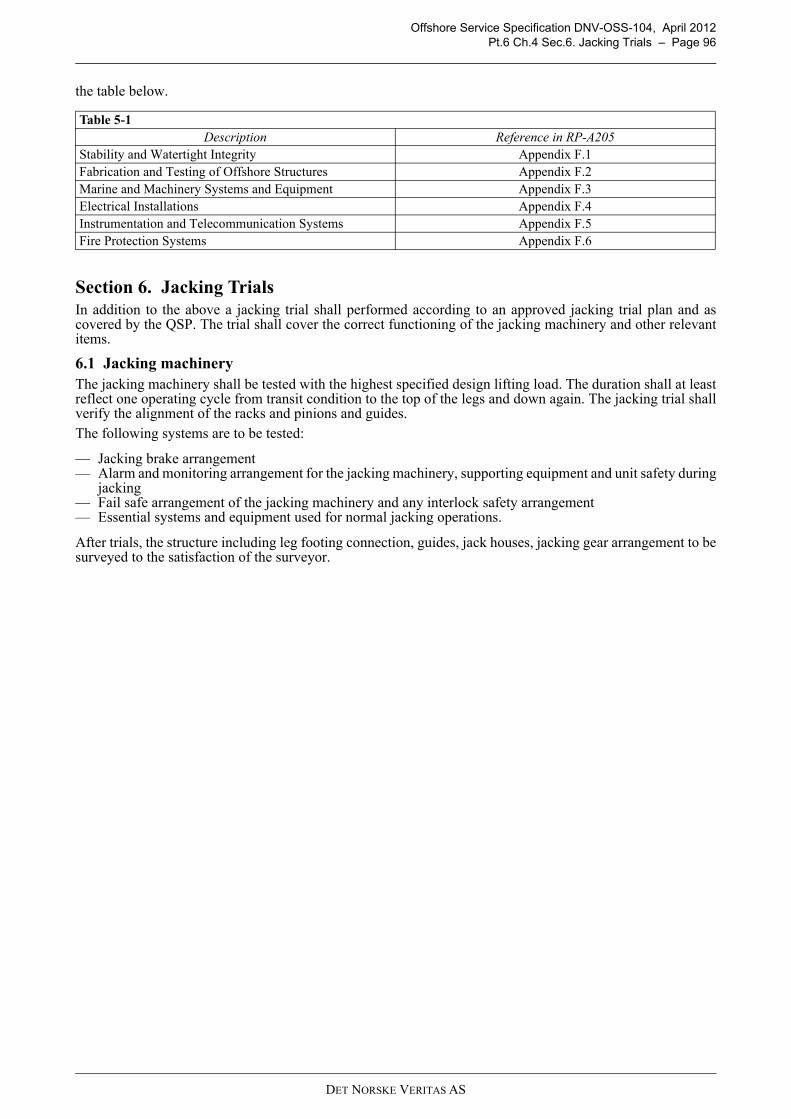
Offshore Service Specification DNV-OSS-104, April 2012Pt.6 Ch.4 Sec.6. Jacking Trials – Page 96
the table below.
Section 6. Jacking TrialsIn addition to the above a jacking trial shall performed according to an approved jacking trial plan and ascovered by the QSP. The trial shall cover the correct functioning of the jacking machinery and other relevantitems.
6.1 Jacking machineryThe jacking machinery shall be tested with the highest specified design lifting load. The duration shall at leastreflect one operating cycle from transit condition to the top of the legs and down again. The jacking trial shallverify the alignment of the racks and pinions and guides.The following systems are to be tested:
— Jacking brake arrangement— Alarm and monitoring arrangement for the jacking machinery, supporting equipment and unit safety during
jacking— Fail safe arrangement of the jacking machinery and any interlock safety arrangement— Essential systems and equipment used for normal jacking operations.
After trials, the structure including leg footing connection, guides, jack houses, jacking gear arrangement to besurveyed to the satisfaction of the surveyor.
Table 5-1 Description Reference in RP-A205
Stability and Watertight Integrity Appendix F.1Fabrication and Testing of Offshore Structures Appendix F.2Marine and Machinery Systems and Equipment Appendix F.3Electrical Installations Appendix F.4Instrumentation and Telecommunication Systems Appendix F.5Fire Protection Systems Appendix F.6
DET NORSKE VERITAS AS
Offshore Service Specification DNV-OSS-104, April 2012Pt.6 Ch.5 Sec.1. Class Certificate – Page 97
CHAPTER 5 DELIVERABLES
Section 1. Class CertificateWhen DNV is satisfied that the requirements specified for the unit in question have been met, the appropriateclass notation will be assigned and confirmed by the issuance of a classification certificate. Provided therequirements for retention of class are complied with, the certificate will normally have a validity of five years.
Section 2. Conditions of ClassClass may be assigned with Conditions of Class.
These conditions may apply for equipment subject to class approval not readily commissioned in accordancewith approved testing and commissioning procedures. The outstanding testing and commission proceduresshould be minor of nature.
Conditions of Class do not apply for critical systems e.g., fire fighting/detection, life-saving appliances andnavigational aids. If these are not commissioned, Class and Statutory Certificates are typically not issued.
Section 3. Appendix to Class CertificateAn “Appendix to the Class Certificate” will be issued stating assumptions for the assignment of class andrestrictions regarding the use of the vessel which were established or assumed at the time of assignment ofclass.
The “Appendix to classification certificate” shall be on board all vessels built to DNV's class.
The appendix contains information on:
1) class notations and register information
2) general and special assumptions related to the particular ship, which may include reference to operationalinstructions.
Section 4. Additional DeclarationsUpon request, declarations confirming compliance with the rules may be issued for hull, machinery or specificclass notations provided the Society's main class has been assigned.
Section 5. Statutory CertificatesThe Society undertakes statutory certification on behalf of flag administrations when and to the extent theSociety has been authorized to do so by the individual flag administration.
Statutory certification includes inter alia approval, survey and the issuance of statutory certificates.
When the Society acts on behalf of a flag administration, the Society follows international statutoryinstruments, IACS Unified Interpretations and DNV Statutory Interpretations, and generally follows guidanceissued by IMO in Circulars etc. unless the flag administration has instructed the Society otherwise.
It is assumed by the Society that required statutory surveys for vessels classed by the Society will be carriedout by the Society or by officers of the flag administration itself and that statutory certificates will be issued bythe Society or by the flag administration with the exceptions mentioned in the paragraphs below. The Societyassumes the right to withdraw class if statutory certificates are not issued as described in this paragraph.
The Society may accept that Safety Management Certificates (ISM Code) are issued by a third party that hasbeen authorized by the flag administration and complies with IMO Resolution A.739(18) and A.789(19).The Society may accept that International Ship Security Certificates (ISPS Code) are issued by a third partythat has been authorized by the flag administration and complies with MSC/Circ.1074.
The Society may accept that Cargo Ship Safety Radio Certificates (SOLAS) are issued by a third party that hasbeen authorized by the flag administration.
For a dually classed vessel, where the Society has not been authorized by the flag administration to issuestatutory certificates, the Society may accept that such certificates are issued by the dual class society providedthe other class society is authorized by the flag administration.
DET NORSKE VERITAS AS
Offshore Service Specification DNV-OSS-104, April 2012Page 98
PART 7 – CLASSIFICATION IN OPERATION
DET NORSKE VERITAS AS
Offshore Service Specification DNV-OSS-104, April 2012Pt.7 Ch.1 Sec.1. Introduction – Page 99
CHAPTER 1 INTRODUCTION
Section 1. IntroductionThis part gives an overview of the survey and inspection of class during the operational phase, focusing on thespecific aspects affecting the safety and reliability of a self-elevating unit in operation. The table below lists references required for a complete understanding of this chapter.
Section 2. ObjectiveThe objective of the classification in operation is to confirm that the vessel, machinery installations andequipment are maintained at a standard complying with the requirements of the rules and by that has anadequate level of safety and quality.
Section 3. ScopeThe technical scope of the class in operation follows the scope as discussed in Pt.1, Sec.2.1. Additional detailsdescribing the scope of involvement of class in operation are given in Section 2.1 of this Part. Inspections for statutory certification are only performed if DNV is authorized to act on the behalf of theNational Authorities on their behalf. This part does not include inspection details for these statutory surveys.
Table 1-1 Reference Title
DNV-OSS-101 Rules for Classification of Offshore Drilling and Support UnitsDNV-OS-C101 Design of Offshore Steel Structures. General (LRFD method)DNV-OS-C104 Structural Design of Self-elevating Units (LRFD method)DNV-OS-C201 Structural Design of Offshore Units (WSD method)DNV-RP-C203 Fatigue Design of Offshore Steel StructuresDNV-RP-C301 Bonded Patch RepairsDNV-RP-C302 Risk based Corrosion Management
DET NORSKE VERITAS AS

Offshore Service Specification DNV-OSS-104, April 2012Pt.7 Ch.2 Sec.1. Conditions for Retention of Class – Page 100
CHAPTER 2 GENERAL PROVISIONS AND REQUIREMENTS FORSURVEYS
Section 1. Conditions for Retention of ClassThe general conditions for the retention of class are given in OSS-101, Ch.1, Sec.5.
Section 2. Class InvolvementThe involvement of class in operation is detailed in OSS-101, Ch.1, Sec.5 B.
2.1 Damage and repairsExcursions from the units design envelop, e.g. punch through or rack phase difference, shall be reported.
Repairs to the hull structure, machinery, systems or equipment covered by the rules shall be carried out byqualified personnel and in compliance with applicable rules, with good engineering practice and under thesupervision of a surveyor.
Repairs as may be carried out without the attendance of a surveyor (e.g. during voyage) provided a repair planis accepted by the Society in advance. A surveyor shall be called for acceptance of such repairs whencompleted.
2.2 Temporary equipmentThe Society shall be informed before the installation of temporary equipment as defined in Sec.1, B200.
Temporary equipment covered by class scope shall be approved and certified in line with normal classprocedures as described in the previous parts.
For temporary equipment outside class scope, it shall be confirmed that placement of this equipment on boarddoes not negatively affect the safety of the unit.
Guidance note:For the consideration, the following is typically to be considered:
- escape ways shall not been blocked- fire and gas system covers the temporary equipment- equipment is covered by the ESD logic- equipment’s load is within deck load limits- definition of hazardous areas takes into account the temp. equipment- interface to other systems covered by main class does not negatively affect their availability.
---e-n-d---of---G-u-i-d-a-n-c-e---n-o-t-e---
Table 1-1 Description Reference in OSS-101, Ch.1, Sec.5
General requirements Sec.5, A100The customer’s obligations Sec.5, A200Class society involvement Sec.5 B, see Section 2 below for further detailsEndorsement and renewal of Class Sec.5 CSuspension and withdrawal of Class Sec.5 DChange of Owner or Manager Sec.5 EFore Majeure Sec.5 F
Table 2-1 Description Reference in OSS-101, Ch.1, Sec.5
Applicable rules Sec.5, B100Surveys Sec.5, B200Conditions and Memoranda Sec.5, B300Survey reports and survey status Sec.5, B400Damage and repairs Sec.5, B500, see belowConversion and alterations Sec.5, B600, see belowTemporary equipment Sec.5, B700, see below
DET NORSKE VERITAS AS

Offshore Service Specification DNV-OSS-104, April 2012Pt.7 Ch.2 Sec.3. Special Provisions for Ageing Units – Page 101
Section 3. Special Provisions for Ageing UnitsTo be able to assess the safety and availability of ageing units, the effects of fatigue shall be taken into account.
Ageing units in this respect are defined as units with nominal age equal to or higher than documented fatiguelife, 20 years if there is no documentation available.
A fatigue utilisation index (FUI) may be calculated. The FUI is defined as the ratio between the effectiveoperational time and the documented fatigue life.
3.1 Calculation of fatigue lifeCalculation of effective operational time shall be based on recorded operations history. For the purpose ofcalculating the FUI, the following may be assumed:
— contribution from operation in harsh environment, e.g. North Sea, North Atlantic and Canada, equals actualoperating time in such environment
— contribution from operation in other environments equals one third (1/3) of actual operating time in suchenvironments
— periods of lay-up and yard stay may be disregarded— contribution from transit operation.
Owner shall submit FUI or historical data allowing for calculation of FUI as part of the planning process priorto renewal survey when the nominal age exceeds the documented fatigue life.
The FUIs may be calculated separately and in detail for various parts of the unit such as:
— leg nodes— spud cans— jack house— deck structure.
The calculations may reflect the various degrees of bottom restraints and loading pattern resulting from thedeck being fixed at various levels during the operations history of the unit.
Guidance note:Based on the above calculation a condition based approach can be applied for the inspection planning. The conditionbased inspection planning can be based on a high level, refined, fatigue analysis as proposed in DNV-RP-C203.
---e-n-d---of---G-u-i-d-a-n-c-e---n-o-t-e---
3.2 Follow upOperation of the unit may continue when the FUI exceeds 1.0 provided the required safety level of the vesselis maintained. If no fatigue cracks have been found in a vessel prior to the FUI reaching 1.0, or if any findingshave been evaluated to have insignificant influence on the fatigue capacity, no special provisions will berequired until such cracks are detected.
For a vessel with FUI > 1.0 and where cracks have been detected in fatigue sensitive areas, the required safetylevel is in general considered satisfied either by increasing the inspection frequency or by performing acondition based assessment for the vessel. The method and procedure applied for the assessment will bereflected in the acceptance of the future inspection program. A guide for condition based inspection planningis given below.
Guidance note:A condition based inspection planning is performed by judging the vessel based on the actual condition rather thanon age in order to maintain the required safety level. In this context a scope implementing all or parts of the followingprocedure can/should be performed:
- Apply the results from a fatigue analysis. The detail level of the analysis will influence the results. Higher detaillevel reduces the uncertainties and increases the confidence in the results and hence reduces the inspectionfrequency.
- Mapping of critical connections w.r.t. fatigue capacity, i.e. ranking of fatigue sensitive details.- Identify details to be modified/upgraded w.r.t. fatigue strength.- Determine required safety level - dependent on consequence and access for inspection.- Apply the fatigue results in a risk based analysis (RBI) including historical data from inspections/findings and
inspection quality for preparing the inspection program.- Evaluate the result from inspections (findings) and/or analysis and perform modifications/improvements ensuring
that the associated risks are adequately controlled.- Perform a continuous updating of the inspection plan based on inspection results.
The inspection plan obtained from a condition based approach is highly dependent on the method and procedureapplied; including the confidence level of the parameters considered. Less confidence increases the probability of
DET NORSKE VERITAS AS

Offshore Service Specification DNV-OSS-104, April 2012Pt.7 Ch.2 Sec.4. Alternative Survey Arrangements – Page 102
failure (PoF) and hence the inspection frequency will increase.
---e-n-d---of---G-u-i-d-a-n-c-e---n-o-t-e---
The Society will issue a MO (Memo to Owner) stating the FUI and agreed compensating measures prior to therenewal survey for the 5-year period in which the FUI exceeds 1.0.The special provisions for maintaining required safety level focus on the fatigue and corrosion properties of thehull and supporting structure. Degradation mechanisms due to ageing effects related to other aspects such asmarine systems must also be given due consideration by owner through maintenance, and by DNV surveyorsthrough regular surveys.Associated plans and procedures, i.e. condition based inspection plans applying risk based approach, shall beapproved by the Society. The scope of the improvement program will depend on the initial assessment andowner's plans for further use of the unit.Units which have undergone an assessment and improvement program as outlined above to the Society'ssatisfaction, will be surveyed based on the modified inspection program.
3.3 Additional inspectionsThe inspections in this section applies only if:
— when the FUI exceeds 1.0 (if calculated) and/or— fatigue deficiencies have been found in fatigue prone and— a condition based approach as discussed in section 3.2 is not considered
Systematic thickness measurements shall be performed at renewal surveys as specified in Sec.4 D207. Ownershall submit a program for such measurements for approval prior to the renewal survey.Owner shall document that the corrosion protection of the unit's hull is adequate and in line with conditionsassumed in original design. The corrosion protection system is to be specially surveyed.The NDE inspection scope as planned for the renewal survey - 5 year interval - is to be performed atintermediate survey- 2½ year interval. The areas subjected for NDE shall be selected with focus on probabilityof cracking and consequence of possible failures. As a guide the following areas should be considered:
— leg connection to spudcan— leg nodes in the bay above the spudcan — leg nodes located above jack house in transport condition— leg nodes located below jack house in operation condition— essential connections within jack house.
The scope for survey of jacking gears as outlined in Ch.4, Sec.3.3.1 shall increase to 20% of jacking gear unitsbut not less than two units per leg.
Section 4. Alternative Survey ArrangementsAlternative survey arrangements may be accepted as an option to applicable periodical surveys for main class.
Section 5. Surveys Performed by Approved CompaniesParts of the periodical surveys may be carried out by companies approved by DNV. The Survey partsperformed by such companies are listed in the table below.
Guidance note:Note that parts of the statutory surveys may be performed by approved companies as well. Examples are inspectionson Fire extinguishers, Life-boat overhaul and Life-rafts. Class is only involved in these services as long as authorisedby flag to perform the statutory surveys on their behalf.
---e-n-d---of---G-u-i-d-a-n-c-e---n-o-t-e---
Table 4-1
Name Description Reference in OSS-101, Ch.3
Machinery continuous Survey arrangement based on surveys of the machinery items Sec.7 CMachinery PMS. a survey arrangement based on a planned maintenance system Sec.7 DMachinery CM Survey arrangement that can include selected parts of the machinery,
and is not covering the complete machinery installation onboardSec.7 E
PMS RCM Survey arrangement based on review of the company management, the RCM analysis and the implemented maintenance system.
Sec.7 G
Offshore CM Condition Monitoring Sec.7 H
DET NORSKE VERITAS AS

Offshore Service Specification DNV-OSS-104, April 2012Pt.7 Ch.2 Sec.5. Surveys Performed by Approved Companies – Page 103
Table 5-1 Description Reference in OSS-101, Ch.3, Sec.3
thickness measurements Sec.3, B200bottom survey afloat Sec.2, B400general NDT Sec.2, B500condition monitoring Sec.2, B600
DET NORSKE VERITAS AS
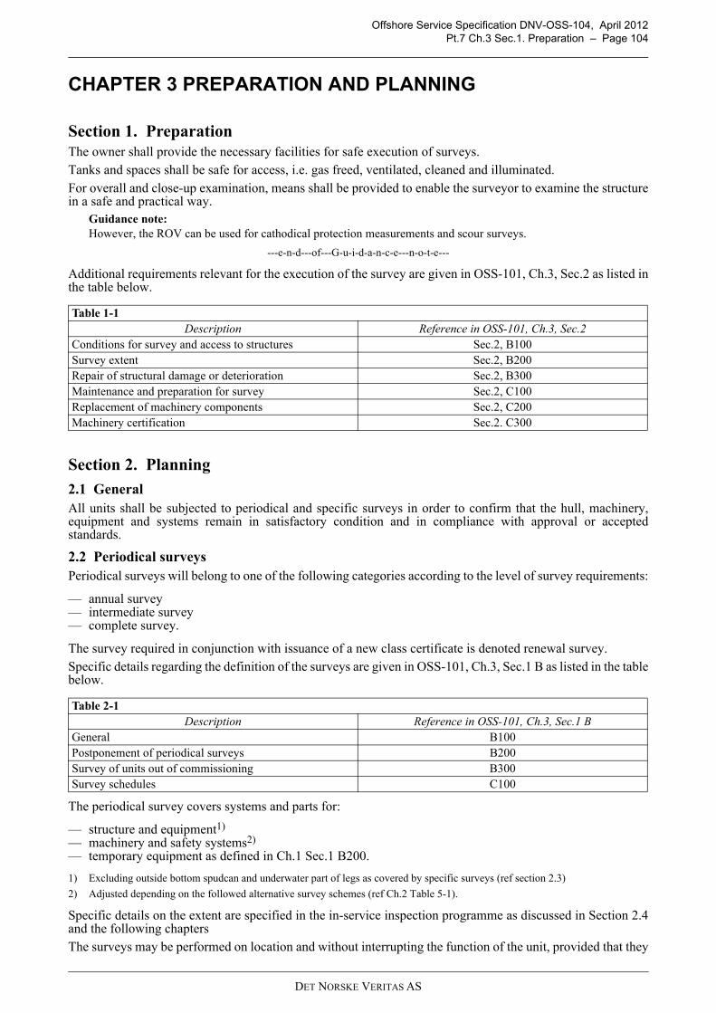
Offshore Service Specification DNV-OSS-104, April 2012Pt.7 Ch.3 Sec.1. Preparation – Page 104
CHAPTER 3 PREPARATION AND PLANNING
Section 1. PreparationThe owner shall provide the necessary facilities for safe execution of surveys.Tanks and spaces shall be safe for access, i.e. gas freed, ventilated, cleaned and illuminated.For overall and close-up examination, means shall be provided to enable the surveyor to examine the structurein a safe and practical way.
Guidance note:However, the ROV can be used for cathodical protection measurements and scour surveys.
---e-n-d---of---G-u-i-d-a-n-c-e---n-o-t-e---
Additional requirements relevant for the execution of the survey are given in OSS-101, Ch.3, Sec.2 as listed inthe table below.
Section 2. Planning
2.1 GeneralAll units shall be subjected to periodical and specific surveys in order to confirm that the hull, machinery,equipment and systems remain in satisfactory condition and in compliance with approval or acceptedstandards.
2.2 Periodical surveysPeriodical surveys will belong to one of the following categories according to the level of survey requirements:
— annual survey— intermediate survey— complete survey.
The survey required in conjunction with issuance of a new class certificate is denoted renewal survey.Specific details regarding the definition of the surveys are given in OSS-101, Ch.3, Sec.1 B as listed in the tablebelow.
The periodical survey covers systems and parts for:
— structure and equipment1)
— machinery and safety systems2)
— temporary equipment as defined in Ch.1 Sec.1 B200.
1) Excluding outside bottom spudcan and underwater part of legs as covered by specific surveys (ref section 2.3)
2) Adjusted depending on the followed alternative survey schemes (ref Ch.2 Table 5-1).
Specific details on the extent are specified in the in-service inspection programme as discussed in Section 2.4and the following chaptersThe surveys may be performed on location and without interrupting the function of the unit, provided that they
Table 1-1 Description Reference in OSS-101, Ch.3, Sec.2
Conditions for survey and access to structures Sec.2, B100Survey extent Sec.2, B200Repair of structural damage or deterioration Sec.2, B300Maintenance and preparation for survey Sec.2, C100Replacement of machinery components Sec.2, C200Machinery certification Sec.2. C300
Table 2-1 Description Reference in OSS-101, Ch.3, Sec.1 B
General B100Postponement of periodical surveys B200Survey of units out of commissioning B300Survey schedules C100
DET NORSKE VERITAS AS

Offshore Service Specification DNV-OSS-104, April 2012Pt.7 Ch.3 Sec.2. Planning – Page 105
are based on approved procedures outlined in a maintenance system and survey arrangement.
2.3 Specific surveysBesides the standard periodical surveys, the following specific surveys are defined:
— Bottom survey (covering external hull) — Spudcan-leg survey (covering spudcans and the underwater areas of legs, together with their connections)— Survey after ocean transit
The bottom survey and spudcan and leg survey are to both to be taken two times in any five (5) year period,with an interval not exceeding three (3) years between examinations. The execution of each these surveys ismutually independent and may be aligned with the units operations.
Guidance note:It is noted that a bottom survey is easy to perform in operating/ elevated condition, while the spudcan and leg surveyis easy to perform during a dry tow.
---e-n-d---of---G-u-i-d-a-n-c-e---n-o-t-e---
Consideration may be given at the discretion of the Society and with acceptance of the flag to any specialcircumstances justifying an extension of the interval.
Guidance note:An example of such a consideration is the spud can and lower leg partly or completely under the mud line. In such acase the spud can- leg survey may be postponed to the next rig move (ref IACS UR Z15 2.3.3).
---e-n-d---of---G-u-i-d-a-n-c-e---n-o-t-e---
Specific surveys are discussed in detail in Ch.5
2.4 In-service Inspection Program (IIP)DNV will develop and maintain an In-service Inspection Program (IIP) which will contain the structural itemsto be surveyed to satisfy the requirements of main class, excluding any additional class notations. The IIPconstitutes the formal basis for surveying structural items under main class and shall be completed to thesatisfaction of attending surveyor before renewal survey can be credited.The In-service Inspection Program (IIP) is developed on the basis of a general, experience-based scope incombination with design and fabrication particulars for the actual unit as well as experience from in-servicesurveys of units of similar type.The basic scope for development of IIP for units of self-elevating type is as given in Table 2-2. The extent ofexamination specified may be modified based on design documentation evaluation, inspection results / crackhistory and experience with similar units /details and may be refined by use of RBI / RCM methodologies.
Guidance note:At the 1st Annual or intermediate survey after construction, column-stabilised and self-elevating units may be subjectto examination of major structural components including non-destructive testing, as deemed necessary by the Society.If the Society deems such survey to be necessary, the extent should be agreed to by the Society and the owner or clientprior to commencement of the Survey.
---e-n-d---of---G-u-i-d-a-n-c-e---n-o-t-e---
Guidance note:See RP-C302 Risk Based Corrosion Management for an RBI approach towards corrosion management.
---e-n-d---of---G-u-i-d-a-n-c-e---n-o-t-e---
DET NORSKE VERITAS AS
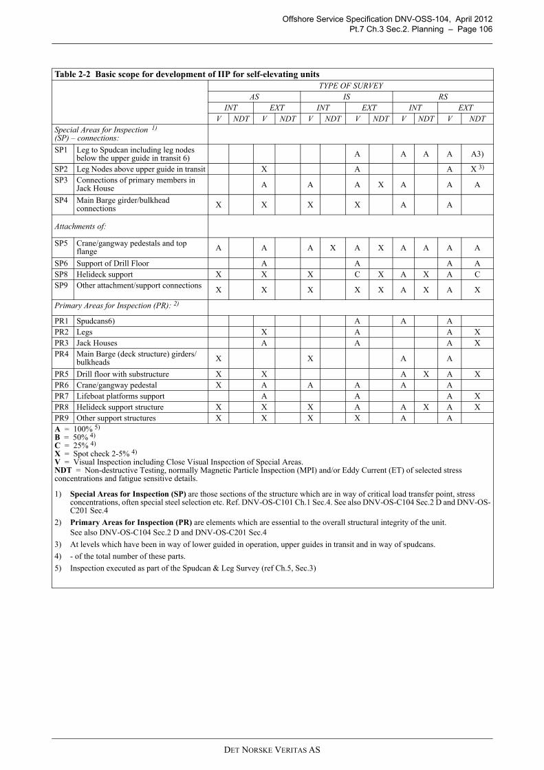
Offshore Service Specification DNV-OSS-104, April 2012Pt.7 Ch.3 Sec.2. Planning – Page 106
Table 2-2 Basic scope for development of IIP for self-elevating unitsTYPE OF SURVEY
AS IS RSINT EXT INT EXT INT EXT
V NDT V NDT V NDT V NDT V NDT V NDTSpecial Areas for Inspection 1)
(SP) – connections:
SP1 Leg to Spudcan including leg nodes below the upper guide in transit 6) A A A A A3)
SP2 Leg Nodes above upper guide in transit X A A X 3)
SP3 Connections of primary members in Jack House A A A X A A A
SP4 Main Barge girder/bulkhead connections X X X X A A
Attachments of:
SP5 Crane/gangway pedestals and top flange A A A X A X A A A A
SP6 Support of Drill Floor A A A ASP8 Helideck support X X X C X A X A CSP9 Other attachment/support connections X X X X X A X A X
Primary Areas for Inspection (PR): 2)
PR1 Spudcans6) A A APR2 Legs X A A XPR3 Jack Houses A A A XPR4 Main Barge (deck structure) girders/
bulkheads X X A A
PR5 Drill floor with substructure X X A X A XPR6 Crane/gangway pedestal X A A A A APR7 Lifeboat platforms support A A A XPR8 Helideck support structure X X X A A X A XPR9 Other support structures X X X X A AA = 100% 5)
B = 50% 4)
C = 25% 4) X = Spot check 2-5% 4)
V = Visual Inspection including Close Visual Inspection of Special Areas.NDT = Non-destructive Testing, normally Magnetic Particle Inspection (MPI) and/or Eddy Current (ET) of selected stress concentrations and fatigue sensitive details.
1) Special Areas for Inspection (SP) are those sections of the structure which are in way of critical load transfer point, stress concentrations, often special steel selection etc. Ref. DNV-OS-C101 Ch.1 Sec.4. See also DNV-OS-C104 Sec.2 D and DNV-OS-C201 Sec.4
2) Primary Areas for Inspection (PR) are elements which are essential to the overall structural integrity of the unit.See also DNV-OS-C104 Sec.2 D and DNV-OS-C201 Sec.4
3) At levels which have been in way of lower guided in operation, upper guides in transit and in way of spudcans.
4) - of the total number of these parts.
5) Inspection executed as part of the Spudcan & Leg Survey (ref Ch.5, Sec.3)
DET NORSKE VERITAS AS
Offshore Service Specification DNV-OSS-104, April 2012Pt.7 Ch.4 Sec.1. Annual Survey – Page 107
CHAPTER 4 PERIODICAL SURVEYS
Section 1. Annual Survey
1.1 Structure and equipment
1.1.1 Hull
Internal surfaces in ballast tanks may be subject to survey, including thickness measurements. The permissiblereduction in thickness is as given for the renewal survey, see also 3.2.
Condition of protective coating is to be reported according to the table below.
For areas with general breakdown of the protective coating, close-up examination and thickness measurementsshall be carried out to an extent sufficient to determine both general and local corrosion levels.
1.1.2 Watertight/ weathertight integrity
Items which are important for the reserve buoyancy in connection with stability of the unit shall be surveyed.The survey shall include inspection of external and internal closing appliances, ventilators, air pipes, sidescuttles etc., as well as an external inspection of scupper valves and sanitary valves.
Remote controls and alarm systems for doors, hatches and watertight dampers shall be surveyed and functiontested.
Guard rails shall be examined.
Guidance note:For units or installations subjected to annual load line inspections by DNV, the requirements in this sub section areconsidered covered by this inspection.
---e-n-d---of---G-u-i-d-a-n-c-e---n-o-t-e---
1.1.3 Towing system
Accessible and visible parts of the unit's permanent towing arrangement and temporary mooring system shallbe inspected
1.1.4 Machinery and safety systems
The survey shall include examination of spaces for machinery, boilers and incinerators, and equipment locatedtherein, with particular attention to fire and explosion hazards. As the DNV surveyor deems necessary, runningtests and/or opening of machinery, and tests of safety devices and equipment may be required.
Boilers shall be externally surveyed. The general condition of the boiler including mountings, piping andinsulation shall be ascertained and the surveyor may require opening, removal of insulation etc. if foundnecessary. Safety valves, instrumentation and automation systems shall be tested in operating condition whenfound necessary by the surveyor.
1.1.5 Jacking system
The brake torques of jacking machinery on self-elevating units shall be checked. Where provided, the fixationrack system shall also be checked.
Spot check on oil sample records.
Table 1-1 Conditions of protective coating Corrosion protection system Is normally to consist of full hard coating supplemented by anodes or full hard
coating.
Guidance note:Other coating systems may be considered acceptable as alternatives provided thatthey are approved by DNV and applied and maintained in compliance with themanufacturer's specification.
---e-n-d---of---G-u-i-d-a-n-c-e---n-o-t-e---
Coating condition “GOOD” Condition with only minor spot rusting. Coating condition “FAIR” Condition with local breakdown at edges of stiffeners and weld connections and/or
light rusting over 20% or more of areas under consideration, but less than as defined for POOR condition.
Coating condition “POOR” Condition with general breakdown of coating over 20% or more of areas or hard scale at 10% or more of areas under consideration.
DET NORSKE VERITAS AS

Offshore Service Specification DNV-OSS-104, April 2012Pt.7 Ch.4 Sec.2. Intermediate Survey – Page 108
1.1.6 Hazardous area
In hazardous areas the following equipment and systems shall be surveyed or tested:
— ventilation systems shall be function tested. The tests shall include emergency stop systems and alarms forlost ventilation
— alarms and shutdown functions for pressurised equipment shall be function tested— gas detection equipment shall be function tested— electrical equipment shall be visually inspected.
Temporary equipment as defined in Ch.1 Sec.1 B200 shall be surveyed.
1.1.7 Drainage, bilge, pre load …
The bilge and system and related subsystems shall be visually surveyed and tested.
1.1.8 General
The «Appendix to the classification certificate» and the documents referred to therein, shall be verified as keptavailable onboard the unit.
For units granted a survey arrangement based on an approved planned maintenance system (PMS), an annualsurvey of the PMS is required to prolong the validity of the arrangement. The purpose of this survey is to reviewand evaluate the previous period's maintenance activities and experience. The annual survey shall consist ofthe following main elements:
a) The maintenance history will be examined in order to verify that the PMS has been operated according tothe intentions and that the system is kept up to date.
b) Evaluation of the maintenance history for main overhaul jobs on the components covered by the continuousmachinery survey (CMS) scheme carried out since last annual survey.
c) Details of corrective actions on components in the CMS scheme shall be made available.
d) If condition monitoring equipment is in use, function tests of this equipment and verification of thecalibration will be carried out as far as practicable and reasonable.
Section 2. Intermediate Survey
2.1 Structure and equipmentThe survey shall, in general, be carried out as the annual survey, but with extended visual inspection and non-destructive testing of the structure as given in the in-service inspection programme (ref Section 2.4).
2.1.1 Legs
Survey of the upper part of the legs is normally required as specified in IIP. Potential measurements will alsobe required if found necessary. See Ch.5 for the inspection of the underwater part of the legs.
2.2 Machinery and systems
2.2.1 Fire protection/ extinguishing/ prevention
The fire protection arrangement shall be surveyed.
Section 3. Renewal Survey
3.1 ExtentThe extent of the survey includes the requirements of the annual and intermediate survey, the items as given inthe in-service inspection program as given in Section 2.4, and additionally the requirements as discussed in thischapter.
For units intended to stay on location for prolonged periods, see Ch.6.
3.2 Structure and equipmentFixation of major appurtenances to the main structure shall be surveyed. These may typically include cranepedestals, helicopter decks, drilling derricks, lifeboat platforms and heavy deck modules or skids.
3.2.1 Legs
The legs above the waterline shall be examined. See Ch.5 for the inspection of the underwater part of the legs.
DET NORSKE VERITAS AS

Offshore Service Specification DNV-OSS-104, April 2012Pt.7 Ch.4 Sec.3. Renewal Survey – Page 109
3.2.2 Acceptance criteria corrosion limitsThickness measurements shall be carried out as deemed necessary by the surveyor at the first and secondrenewal surveys after delivery. At the third renewal and subsequent renewals, in addition to the above,mandatory thickness gaugings are to be taken as a minimum in the following areas:
— major connections of leg to mat— lattice leg chord at connections to spudcan— spudcan bulkheads at connections to leg chord— leg chords in way of splash zone— load transfer area in way of jack house (external and in way of pre load tanks).
In addition to the above, spot checks may be taken in other areas in order to assess the general condition of theunit.
Guidance note:Recommended locations for the spot checks are the main deck (often problem area due to frequent deck loading/unloading) and pre-load tanks.
---e-n-d---of---G-u-i-d-a-n-c-e---n-o-t-e---
Average corrosion is defined as the average corrosion rate for a typical structural member. Local corrosion is defined as the local corrosion limited by an area of 500 × 500 mm within a plate-field definedby two stiffeners and adjacent web-frames.Table 3-1 specifies the allowable reduction for the two specific areas.
Guidance note:It is noted that general designs do not take into account additional corrosion margins. Notwithstanding, if these areincluded and documented, the reduction as specified in the table is exclusive this margin and the total allowablereduction is the margin + a specified share of the plate/member thickness. For DNV requirement for corrosion margin is referred to DNV-OS-C101, Sec.10, B407
---e-n-d---of---G-u-i-d-a-n-c-e---n-o-t-e---
3.2.3 Tanks Tanks shall, as a minimum, be internally surveyed in accordance with Table 3-2 (as far as applicable).Survey of pipes, valves, couplings, anodes, equipment for level indication, etc. inside tanks and spaces shall becarried out.
Table 3-1 Average corrosion Local corrosion— 5% reduction is allowed in “special” areas subject to
high fatigue loads. These areas are normally identifiedin the In-Service Inspection Program (IIP)
— 10% reduction is allowed in areas taking part in the global structural strength, or being part of the watertight integrity of the unit
— 15% reduction is allowed in areas not taking part in the global structural strength and not being part of the watertight integrity of the unit.
— 5% reduction is allowed in “special” areas subject to high fatigue loads. These areas are normally identified in the In-Service Inspection Program (IIP)
— 15% reduction is allowed for plates in areas taking part in the global structural strength, or being part of the watertight integrity of the unit
— 20% reduction is allowed in areas not taking part in the global structural strength and not being part of the watertight integrity of the unit.Detailed locations for thickness gaugings will be included in the vessels In-service Inspection Programme
DET NORSKE VERITAS AS

Offshore Service Specification DNV-OSS-104, April 2012Pt.7 Ch.4 Sec.3. Renewal Survey – Page 110
Remote level indicating systems for ballast tanks shall be surveyed and function tested.Remote control system for valves in bilge, ballast and cooling water systems shall be surveyed and tested.Tank bulkheads and tank decks integral with the unit structure shall, as a minimum, be hydraulically testedfrom at least one side to the maximum pressure they can be subjected to in service. The number of tanks to betested shall be in accordance with Table D1, as far as applicable.
3.3 Weight/ displacement surveyThe unit is to undergo a weight or displacement survey and the weight record will be checked in order to verifythe current lightweight and centre of gravity. Where the weight survey indicates a difference from thecalculated lightweight in excess of 5% of the operating displacement, an inclining test should be conducted. Itis a provision that the weight difference is positioned at the most unfavourable position when calculating thevertical centre of gravity (VCG).The above mentioned requirements may be considered complied with where the national authorities enforcesimilar requirements. In such cases a copy of the report on the weight survey, or on the new inclining test,endorsed by the national authorities, shall be submitted.
3.3.1 Towing equipment The permanent towing arrangement of the unit shall be surveyed. Towing equipment is subject to visualinspection.
3.4 Machinery and systems
3.4.1 GeneralThe survey shall comprise examination of the electrical installations with regard to fire and explosion hazardsand injury from accidental touching. The survey is also to include testing of correct functioning of equipmentcovered by class requirements.The insulation resistance of the complete installation shall be measured, and the results presented to thesurveyor.For vessels Survey arrangement PMS and with continuous earth fault monitoring of all distribution systemsand alarm to a continuously manned control station, the following alternative may be accepted:
— megger test of all generators and main electrical motors— test of all earth fault monitoring devices— verification that the vessel have regular maintenance routines for test of earth fault monitoring devices.
As far as practicable, the following equipment shall be examined for satisfactory condition:
— main and emergency switchboards— generators— distribution boards— motor starters— electrical motors
Table 3-2 Tank survey and pressure testing 1), 2)
Tank Age of unit in years0-5 5-10 10-15 above 15
Sea water 3) All all all allFresh water One one all allFuel and sludge One one two halfLubricating oil None none one halfNotes:
1) Tanks of integral type
Guidance note:Integral tanks form a part of the unit’s hull and are influenced in the same manner and by the same loads that stressthe adjacent hull structure.Independent tanks within machinery spaces (non-integral, self-supporting tanks which do not form part of the unit'shull) are normally surveyed as part of the renewal survey for machinery, see E.
---e-n-d---of---G-u-i-d-a-n-c-e---n-o-t-e---
2) If selection of tanks is accepted to be surveyed, then different tanks shall, as far as practicable, be surveyed at each survey, on a rotational basis.
3) Tanks used as bilge water holding tanks, shall be examined as required for sea water tanks.
DET NORSKE VERITAS AS

Offshore Service Specification DNV-OSS-104, April 2012Pt.7 Ch.4 Sec.3. Renewal Survey – Page 111
— converters (e.g. transformers, rectifiers, chargers)— cable installations— enclosures for electrical equipment— lighting equipment— heating equipment— battery installations.
The following tests shall be carried out to the extent deemed necessary by the surveyor to ascertain the properfunctioning of the equipment:
— generator full load test; minimum load for life support and emergency jacking should be guaranteed— generator parallel operation— generator protection relays including non-important load trip, if fitted— generator remote speed control— generator synchronising equipment— power plant interlocking systems— insulation resistance indicating device— emergency generator including switchboards— battery chargers— navigation lights, with controllers including alarms— electrical motors for essential and important use, e.g. for jacking system at full load— interlocking and/or alarms for pressurised rooms and equipment.— air systems and their redundancy as part of safety- or important systems.
3.4.2 Jacking system
The jacking systems, including shock pads, shall be examined in the presence of the Surveyor by the originalequipment manufacturer or other third party inspector mutually agreeable to the owner and the Surveyor.
The inspection shall include the following:
a) Racks and climbing pinions (visual examination for wear and proper tooth contact).
b) Planetary gear boxes (opening and visual examination of at least one per leg, oil analyses for all).1)
c) Linear gearboxes (can be inspected by means of endoscope or inspection covers when provided).
d) Braking systems (opening and visual examination of at least one per leg).
e) Pinions (pinion clearance if accessible).
f) Survey & NDT of jacking guides to the extent possible to be included.
g) Leg guide clearance to be checked with design specifications.2)
1) Oil samples are to be collected directly after a jacking operation to ensure representative values
2) A leg guide clearance above design specification may result in additional load to jacking gear and its bearings with a subsequentincrease of wear. In addition a too high clearance may result in out of straightness of legs resulting in binding during jackingoperations.In addition NDT is to be carried out in line with the In-Service Inspection Plan (ref section 2.4).
3.4.3 Raw water pumps
Check availability of water supply for safety systems, i.e fire water for different operational conditions (transit,during jacking and in elevated conditions).
3.4.4 Hazardous area
Enclosed hazardous areas such as those containing open active mud tanks, shale shakers, de-gassers and de-sanders are to be examined and doors and closures in boundary bulkheads verified as effective. Electriclighting, electrical fixtures, and instrumentation are to be examined, proven satisfactory and verified asexplosion-proof or intrinsically safe. Ventilating systems including ductwork, fans, intake and exhaustlocations for enclosed restricted areas are to be examined, tested and proven satisfactory. Ventilating air alarmsystem is to be proven satisfactory. Electrical motors are to be examined including closed-loop ventilatingsystems for large D-C motors. Automatic power disconnect to motors in case of loss of ventilating air is to beproved satisfactory.
3.4.5 Fire protection/ extinguishing/ prevention
Correct functioning of the various parts of the following systems shall, as far as applicable, be verified:
— alarm and safety system— fire and gas detection systems.
DET NORSKE VERITAS AS

Offshore Service Specification DNV-OSS-104, April 2012Pt.7 Ch.4 Sec.3. Renewal Survey – Page 112
3.4.6 Instrumentation and automationWhen cancelling of automatic load reduction and/or automatic stop of engine are provided, these functionsshall be demonstrated to the surveyor.Remote shutdown for fuel-oil transfer service pumps and ventilating equipment, together with oil tank outletvalves where required to be capable of being remotely closed are to be proved satisfactory. Emergencyswitch(es) for all electrical equipment including main and emergency generators, except alarm andcommunication systems and lighting in vital areas such as escape routes and landing platforms, are to be provedsatisfactory (by a combination of testing and review of maintenance records).(IACS UR Z15)A test showing the correct ESD system functioning.
Guidance note:To prevent negative consequences on ongoing operations it is recommended to prepare the test in collaboration withthe surveyor. In addition, it may be advantage to execute these test where negative consequences are limited, e.g.during casing setting.
---e-n-d---of---G-u-i-d-a-n-c-e---n-o-t-e---
3.5 GeneralThe presence of required signboards shall be verified.
DET NORSKE VERITAS AS
Offshore Service Specification DNV-OSS-104, April 2012Pt.7 Ch.5 Sec.1. Record Keeping – Page 113
CHAPTER 5 OTHER SURVEYS
Section 1. Record Keeping Plans and procedures for underwater inspection shall be submitted for review in advance of the survey andmade available on board. Submitted data, after review by the Society, will be subject to revision if found to benecessary in light of experience.
Guidance note:The Society may consider alternative methods for providing adequate assurance that a unit's bottom is in a satisfactorycondition at the mid-term class period survey.A survey based on such alternative methods is subject to acceptance by the relevant flag administration.
---e-n-d---of---G-u-i-d-a-n-c-e---n-o-t-e---
Section 2. Bottom SurveyFor the interval of the bottom survey see Ch.3 Sec.2.3.
The bottom survey afloat may replace the statutory dry docked survey provided acceptance from the flag.Underwater Inspection in lieu of Drydocking Survey may not be acceptable where there is record of abnormaldeterioration or damage to the underwater structure; or where damage affecting the fitness of the unit is foundduring the course of the survey.
Valves are checked for proper condition / closing and operation, often fitted with remote operation by meansof rod extensions etc
Sea chests and other sea inlets and discharges (above and below the waterline) with valves, including sanitaryvalves and scupper valves, shall be opened for survey.
Section 3. Spudcan & Leg Survey
3.1 GeneralFor the interval of the Spudcan and Leg survey see Ch.3 Sec.2.3.
Considerations shall be given to safe entry and accessibility of the spudcans before the survey. Guidance note:The considerations include ventilation, arrangements for pumps, cables for lighting etc.
---e-n-d---of---G-u-i-d-a-n-c-e---n-o-t-e---
3.2 ScopeThe spudcan & leg survey includes the leg nodes below the upper guide in transit. The nodes above this guideare inspected during the normal periodical surveys.
3.3 InspectionExternal surfaces of spudcans, mat, underwater areas of legs, together with their connections as applicable,shall be selectively cleaned to the satisfaction of the attending surveyor and examined.
The surveyor is to be satisfied with the condition of the internal structure of the spudcans. Leg connections tospudcans are to be examined at each dry-dock survey or equivalent
The cathodic protection system of the submerged zone shall be surveyed. The efficiency of the system for theforthcoming 5-year period shall be confirmed.
The cathodic protection system shall be surveyed by visual inspection of sacrificial anodes and extent ofcorrosion. Corrosion in welds of vital parts which may be subject to fatigue shall be particularly considered.
Section 4. Survey after Ocean TransitAfter an ocean transit, a survey is to ensure that the unit is in sound condition and did not suffer from damagefrom bad weather during the transit, otherwise consequences of inappropriate shimming of the legs. This post-transit survey applies both for wet and dry tows and shall be carried out before elevating the unit.
The survey shall consist of the visual inspection and NDT testing with a focus on the following structural areas:
— Jackhouse structure and connection to the hull,
DET NORSKE VERITAS AS

Offshore Service Specification DNV-OSS-104, April 2012Pt.7 Ch.5 Sec.4. Survey after Ocean Transit – Page 114
— Leg Nodes in way of upper/lower guides and chord spudcan connection.— Main deck area in way of support of gearboxes.
The owner is to prepare a survey plan including details of the tow to be submitted to the Society for approvalprior to commencement.The owner may perform the survey himself. If the survey reveals damages, DNV is to be involved in line withChapter 2, Section 2.1. If no damages are found, inspection records are to be shown at the next periodicalsurvey.
DET NORSKE VERITAS AS

Offshore Service Specification DNV-OSS-104, April 2012Pt.7 Ch.6 Sec.1. Introduction – Page 115
CHAPTER 6 PERMANENTLY INSTALLED SELF-ELEVATINGUNITS
Section 1. IntroductionThe requirements and guidance given in Chapter are supplementary requirements for units that are intended tostay on location for prolonged periods, normally more than 5 years.Permanently installed self-elevating units shall be designed or documented for the site specific environmentaland soil conditions. Fatigue properties and facilities for survey on location shall be specially considered.Adequate corrosion protection shall be implemented to cover the entire prolonged operation period.
Section 2. FatigueDesign Fatigue Factors (DFF) are introduced as fatigue safety factors. DFF shall be applied to structuralelements according to the principles in DNV-OS-C101. Fatigue safety factors applied for permanently installed self-elevating units shall be given dependent on thecriticality of the detail and accessibility for inspection and repair. Special considerations should be made forthe leg in the splash zone, submerged parts legs and spudcan, and possible inaccessible parts of the spudcan.The fatigue analysis should focus on members that are essential to the overall structural integrity of the unit. Fatigue susceptible areas may include:
— the leg to hull holding system— the leg members and joints in the vicinity of the upper and lower guides— the leg members and joints in the splashing zone— the leg members and joints in the lower part of the leg near the spudcan— the spudcan to leg connection.
Guidance note:See DNV-OS-C101 Sec.10 B200 with respect to vertical extent of splash zone.
---e-n-d---of---G-u-i-d-a-n-c-e---n-o-t-e---
Section 3. Inspection and Maintenance
3.1 Facilities for surveySurveys may be carried out on location based on agreed procedures outlined in a maintenance system andsurvey arrangement, without interrupting the function of the unit. The following matters shall be taken intoconsideration to be able to carry out surveys on location:
— arrangements and methods for survey of hull, legs and seabed foundation structure— corrosion protection of hull, legs and seabed foundation structure— underwater cleaning facilities.
The In Service Inspection program (IIP) should reflect possible stress concentrations in critical areas, fatiguecriticality, and the previous operational and inspection histories.
Section 4. Jacking SystemWhen the jack up unit is intended for permanently installation as defined in section 1 and has arrangements fora fix load transfer by a permanent fixation system, the jacking system will be excluded from DNV scope ofwork for classification after the initial jacking of the unit.
DET NORSKE VERITAS AS