DNV-OSS-314: Verification of Hydrocarbon Refining and ...
76
SERVICE SPECIFICATION DET NORSKE VERITAS DNV-OSS-314 VERIFICATION OF HYDROCARBON REFINING AND PETROCHEMICAL FACILITIES APRIL 2010
Transcript of DNV-OSS-314: Verification of Hydrocarbon Refining and ...
SERVICE SPECIFICATION
DET NORSKE VERITAS
DNV-OSS-314
VERIFICATION OF HYDROCARBON REFINING
AND PETROCHEMICAL FACILITIES
APRIL 2010
FOREWORDDET NORSKE VERITAS (DNV) is an autonomous and independent foundation with the objectives of safeguarding life, prop-erty and the environment, at sea and onshore. DNV undertakes classification, certification, and other verification and consultancy services relating to quality of ships, offshore units and installations, and onshore industries worldwide, and carries out research in relation to these functions.DNVCodes consist of a three level hierarchy of documents:— Service Specifications. Provide principles and procedures of DNV classification, certification, verification and consultancy
services.— Standards. Provide technical provisions and acceptance criteria for general use by the industry as well as the technical basis
for DNV services.— Recommended Practices. Provide proven technology and sound engineering practice as well as guidance for the higher level
Service Specifications and Standards.DNV Codes are offered within the following areas:A) Qualification, Quality and Safety MethodologyB) Materials TechnologyC) StructuresD) SystemsE) Special FacilitiesF) Pipelines and RisersG) Asset OperationH) Marine OperationsJ) Cleaner EnergyO) Subsea Systems
Amendments and Corrections This document is valid until superseded by a new revision. Minor amendments and corrections will be published in a separatedocument normally updated twice per year (April and October). For a complete listing of the changes, see the “Amendments and Corrections” document located at: http://webshop.dnv.com/global/.The electronic web-versions of the DNV Codes will be regularly updated to include these amendments and corrections.
Comments may be sent by e-mail to [email protected] subscription orders or information about subscription terms, please use [email protected] information about DNV services, research and publications can be found at http://www.dnv.com, or can be obtained from DNV, Veritasveien 1, NO-1322 Høvik, Norway; Tel +47 67 57 99 00, Fax +47 67 57 99 11.
© Det Norske Veritas. All rights reserved. No part of this publication may be reproduced or transmitted in any form or by any means, including photocopying and recording, without the prior written consent of Det Norske Veritas.
Computer Typesetting (Adobe FrameMaker) by Det Norske Veritas.
If any person suffers loss or damage which is proved to have been caused by any negligent act or omission of Det Norske Veritas, then Det Norske Veritas shall pay compensation to such personfor his proved direct loss or damage. However, the compensation shall not exceed an amount equal to ten times the fee charged for the service in question, provided that the maximum compen-sation shall never exceed USD 2 million.In this provision "Det Norske Veritas" shall mean the Foundation Det Norske Veritas as well as all its subsidiaries, directors, officers, employees, agents and any other acting on behalf of DetNorske Veritas.
Service Specification DNV-OSS-314, April 2010Introduction – Page 3
BackgroundThe experience gained from past projects specific to an oilrefinery and a petrochemical plant is incorporated in this Serv-ice Specification.
Scope of documentThis Service Specification:
— describes DNV's verification services for oil refineries andpetrochemical facilities,
— provides guidance for facility Owners and others for the selec-tion of the level of involvement of those carrying out the cer-tification and verification activities, whether by simple triggerquestions or as a result of a quantitative risk assessment
— provides a common platform for describing the scope andextent of verification activities.
— identifies typical risk critical equipment and the appropri-ate level of verification activities recommended to meetthe verification objective and requirements.
DET NORSKE VERITAS

Service Specification DNV-OSS-314, April 2010Page 4 – Introduction
DET NORSKE VERITAS
Service Specification DNV-OSS-314, April 2010 Contents – Page 5
CONTENTS
Sec. 1 Introduction To Risk-based Verification............ 7
A. Introduction ............................................................................7A 100 Function of this Document ............................................... 7A 200 Objectives ......................................................................... 7A 300 Scope of Application for Verification .............................. 7A 400 Structure of this Document ............................................... 7
B. Risk-based Verification ..........................................................7B 100 General.............................................................................. 7B 200 Verification’s Role in Hazard Management ..................... 7B 300 Risk-based Verification Planning ..................................... 8B 400 Certificate of Conformity.................................................. 8
C. Definitions ..............................................................................8C 100 Verbal Forms .................................................................... 8C 200 Definitions ........................................................................ 8
D. Abbreviations........................................................................ 10
E. References ............................................................................10
Sec. 2 Principles of Risk-based Verification................ 11
A. Purpose of Section ................................................................11A 100 Objectives ....................................................................... 11
B. Verification Principles ..........................................................11B 100 Purpose of Verification................................................... 11B 200 Verification as a Complementary Activity ..................... 11B 300 Risk-based Levels of Verification .................................. 11
C. Selection of Level of Verification .......................................11C 100 Selection Factors............................................................. 11C 200 Overall Safety Objective................................................. 12C 300 Assessment of Risk......................................................... 12C 400 Technical Innovation and Contractor Experience .......... 13C 500 Quality Management Systems ........................................ 13
D. Communications...................................................................13D 100 Notification of Verification Level .................................. 13D 200 Obligations...................................................................... 13
Sec. 3 Service Overview ................................................ 14
A. Purpose of Section ................................................................14A 100 Objectives ....................................................................... 14
B. Service Process .....................................................................14B 100 General Principles........................................................... 14B 200 Scopes of Work............................................................... 14
C. FEED ....................................................................................14C 100 Verification During FEED.............................................. 14
D. Project Design, Construction and Commissioning ..............................................................15
D 100 General............................................................................ 15D 200 Verification of Overall Project Management.................. 15D 300 Verification during Design ............................................. 15D 400 Verification During Construction ................................... 15D 500 Verification During Commissioning .............................. 16
E. Operations.............................................................................17E 100 General............................................................................ 17E 200 Verification of Overall Operations Management ........... 17E 300 Verification During Operations ...................................... 18
F. Facility Modifications...........................................................18F 100 Reasons for Modifications .............................................. 18F 200 Particular Aspects of Modifications to Hydrocarbon
Facilities.......................................................................... 18F 300 Verification During the Design of Modifications........... 18F 400 Verification During the Construction of Modifications .18F 500 Verification During the Commissioning
of Modifications.............................................................. 19
App. A Selection of Verification Level........................... 20
A. Introduction...........................................................................20A 100 General Principles........................................................... 20
B. Quantitative Risk Assessment ..............................................20B 100 Use of a Quantitative Risk Assessment .......................... 20B 200 Scope of a QRA.............................................................. 20B 300 Risk Assessment ............................................................. 20B 400 Hazard Identification ...................................................... 21B 500 Frequency Estimation ..................................................... 21B 600 Consequence Criteria...................................................... 21B 700 Consequence Analysis .................................................... 21B 800 Domino Effect Analysis ................................................ 21B 900 Risk Summation and Evaluation .................................... 21B 1000 Sensitivity Analysis ........................................................ 21B 1100 Assessment of Risk Mitigation Measures....................... 21
C. Trigger Questions .................................................................21C 100 Use of Trigger Questions................................................ 21C 200 Overall Safety Objective................................................. 21C 300 Assessment of Risk......................................................... 22C 400 Technical Innovation ...................................................... 22C 500 Contractors’ Experience ................................................. 22C 600 Quality Management Systems ........................................ 22
App. B Verification Documents ..................................... 23
A. Purpose of Appendix ............................................................23A 100 Introduction..................................................................... 23A 200 Issue and Filing of Certificates ....................................... 23A 300 Validity of Verification Documents ............................... 23
B. DNV Certificate of Conformity............................................23B 100 Definition........................................................................ 23B 200 Scope of Verification to Obtain a DNV Certificate
of Conformity ................................................................. 23
C. Statement of Compliance .....................................................23C 100 Definition........................................................................ 23C 200 Scope of Verification to Obtain a Statement
of Compliance................................................................. 23
D. Other Verification Documents..............................................23D 100 Verification Reports........................................................ 23D 200 Verification Comments Sheets ....................................... 24D 300 Visit Reports ................................................................... 24
E. Use of Quality Management Systems ..................................24E 100 General............................................................................ 24E 200 Quality Plans................................................................... 24E 300 Inspection and Test Plans ............................................... 24E 400 Review of Quality Management Programme ................. 24
F. Verification Forms................................................................25F 100 Specimen Forms ............................................................. 25F 200 Certificate of Conformity ............................................... 26F 300 Statement of Compliance................................................ 27F 400 Verification Comments Sheet......................................... 28F 500 Visit Report..................................................................... 29
App. C Generic Detailed Verification Scopes of Work Tables ................................................... 33
A. Purpose of Appendix ............................................................33A 100 Introduction..................................................................... 33
B. Description of Terms Used in the Scope of Work Tables ................................................33
B 100 Abbreviations and Terms................................................ 33B 200 Audit ............................................................................... 33B 300 Surveillance .................................................................... 33B 400 Hold Point....................................................................... 33B 500 Review ............................................................................ 33
DET NORSKE VERITAS
Service Specification DNV-OSS-314, April 2010 Page 6 – Contents
C. Overall Project Management ................................................ 34C 100 Availability of Documents ..............................................34C 200 Detailed Scope of Work for Overall Project
Management....................................................................34
D. Design................................................................................... 34D 100 General ............................................................................34D 200 Design Verification .........................................................34D 300 Low Level Design Verification.......................................34D 400 Medium Level Design Verification ................................34D 500 High Level Design Verification ......................................34D 600 Safety-critical Elements and Components ......................34D 700 Scope of Work for Design ..............................................36
E. Construction.......................................................................... 47E 100 General ............................................................................47E 200 Construction Verification................................................47E 300 Low Level Construction Verification .............................47E 400 Medium Level Construction Verification .......................47E 500 High Level Construction Verification.............................47E 600 Verification of Work in Progress ....................................47E 700 DNV Final Report ...........................................................48E 800 Scope of Work for Construction .....................................48
F. Commissioning..................................................................... 54F 100 General ............................................................................54F 200 Commissioning Verification ...........................................54F 300 Low Level Commissioning Verification.........................54F 400 Medium Level Commissioning Verification ..................54F 500 High Level Commissioning Verification ........................54F 600 Verification of Work in Progress ....................................54F 700 DNV Final Report ...........................................................55F 800 Scope of Work for Commissioning Verification ............55
G. Operations............................................................................. 58G 100 General ............................................................................58G 200 Operations Verification...................................................58G 300 Low Level Operations Verification ................................58G 400 Medium Level Operations Verification ..........................58G 500 High Level Operations Verification................................59G 600 DNV Final Report ...........................................................59G 700 Scope of Work for Operations Verification ....................59
H. Modifications or Upgrades ................................................... 66H 100 General Principles ...........................................................66
H 200 Verification of Design of Modifications.........................66H 300 Verification of Construction of Modifications................67H 400 Verification of Commissioning of Modifications...........67
App. D Major Accident Hazards Versus Safety-critical Elements..................................... 68
A. Purpose of Appendix ............................................................68A 100 Introduction.....................................................................68
App. E Guidance on the Development of Verification Plans........................................... 72
A. Purpose of Appendix ............................................................72A 100 Introduction.....................................................................72
B. The Verification Plan’s Part in Facility Risk Management................................................72
B 100 Risk Reduction in Principle ............................................72B 200 The Major Accident Hazard Process and Integrity
Management....................................................................72
C. Independent Third-Party Verification...................................72C 100 What is Verification? ......................................................72C 200 How Verification Is Carried Out.....................................73C 300 Content of Verification Plan ...........................................73C 400 Formal Guidance on Verification Plans and Practices....73
D. Verification Plan...................................................................73D 100 Development of the Verification Plan ............................73D 200 Development of Examination Scope
of Work Documents ........................................................73D 300 Methods of Examination.................................................73D 400 Project Phase ...................................................................73D 500 Control of Verification....................................................74
E. Verification Reporting ..........................................................74E 100 Control of Verification Reports ......................................74E 200 Verification Status Reporting..........................................74
F. Review and Revision of the Verification Plan .....................75F 100 Continuous Review of the Plan.......................................75F 200 Events Initiating Revisions .............................................75
DET NORSKE VERITAS
Service Specification DNV-OSS-314, April 2010 Sec.1 – Page 7
SECTION 1INTRODUCTION TO RISK-BASED VERIFICATION
A. Introduction
A 100 Function of this Document101 This Service Specification gives criteria for and guid-ance on third-party verification of the safety and integrity ofhydrocarbon refineries and petrochemical facilities during newdevelopments, operations and during modifications to existingfacilities.102 This document is an object-specific Service Specifica-tion conforming to the philosophy defined in DNV-OSS-300Risk-based Verification, ref. Sec.1 E.
A 200 Objectives201 The objectives of this document are to:
— describe DNV’s verification services for hydrocarbonrefineries and petrochemical facilities during:
— design— construction— commissioning— operations— modification.
— provide guidance for facility Owners and other parties forthe selection of the level of involvement of those carryingout verification activities, whether quantitatively as aresult of a quantitative risk assessment or qualitatively bysimple trigger questions.
— provide a common platform for describing the scope andextent of verification activities.
A 300 Scope of Application for Verification301 This OSS may be adopted for the verification of all partsof all hydrocarbon refineries or types of petrochemical facili-ties or selected project phases.302 This OSS describes the principle of a levelled verifica-tion involvement, where the extent of verification involvementis linked to the risks associated with part or all of the facility.303 The primary scope of DNV’s verification work is theverification of the integrity of hydrocarbon facilities and thesafety of its personnel and those in close proximity to it. Otheraspects, such as the verification of the environmental impact ofthe facility, or its ability to meet the Owner’s business objec-tives, may be included in DNV’s scope of work if desired bythe Owner.304 Statutory verification (or certification) of hydrocarbonfacilities to the requirements of National Authorities is notincluded specifically in the scope of application of this OSS.Such verification (or certification) shall be governed by theregulations of the relevant Authority. However, if detailed pro-cedures are not given by these Authorities, this OSS will beused by DNV as a guideline for its work.
A 400 Structure of this Document401 This document consists of three sections and five appen-dices:
— Section 1, this section, explains the relationship between
this document and DNV’s overall risk-based verificationprocess.
— Section 2 explains the principles of DNV’s verificationprocess with its risk-based levels of involvement, and howthe level of involvement for a particular project is defined.
— Section 3 describes the verification process and the activ-ities for each of the project phases.
— Appendix A gives guidance on the selection of verificationlevel, preferably as the result from a quantitative riskassessment or alternatively, qualitatively as a result of theposing of trigger questions.
— Appendix B gives examples of verification documents.The use of quality management systems is addressed here.
— Appendix C gives a generic detailed scope of work tablesfor all phases and all levels of involvement. These tablesare the basis for the development of project-specificscopes of work tables.
— Appendix D gives typical refinery hazards and their inter-face with safety-critical elements and risk mitigationmeasures.
— Appendix E gives guidance on the formulation of plans forthe verification of the design, construction and commis-sioning of hydrocarbon facilities.
B. Risk-based Verification
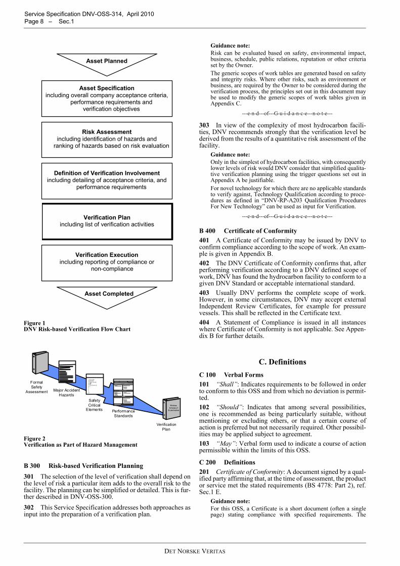
B 100 General101 This OSS describes the principles of verification of thesafety and integrity of hydrocarbon facilities for all phases.102 The risk based verification concept is described inDNV-OSS-300 and visualized in Figure 1 overleaf.103 The Verification Plan is the pivot element, with theAsset Specification, Risk Assessment and Definition of Veri-fication Involvement as input and the Verification Executionbeing the implementation.
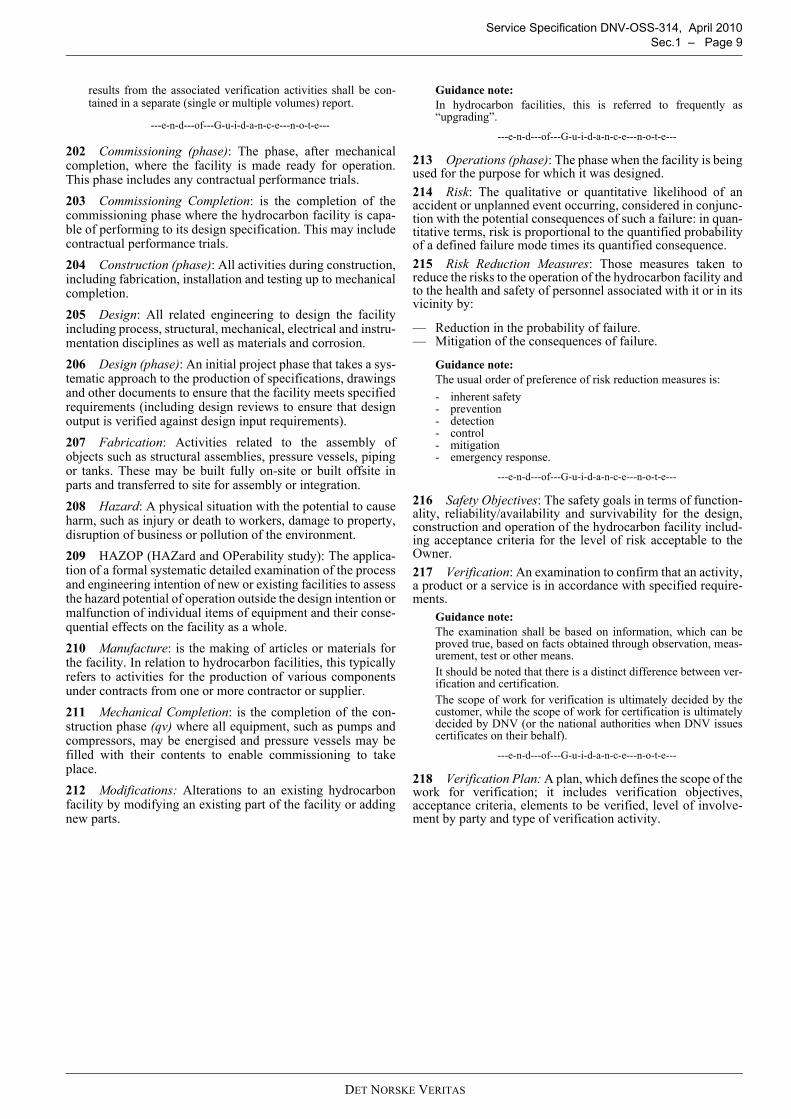
B 200 Verification’s Role in Hazard Management201 Major Accident Hazards are identified in a FormalSafety Assessment by an analysis of the risks to the facility’spersonnel using suitable definitions of such accidents.202 Safety-critical Elements are those hardware-relatedmeasures, including computer software, designed to reduce therisk to the facility’s personnel.203 Performance Standards are the definitions of how thesesafety-critical elements perform their risk reduction functions.204 Verification Plan is how an independent examination ofthese safety-critical elements is planned to confirm that theyare suitable and fulfil the safety and integrity requirements ofthe facility’s Owner.A graphical representation of this process is shown in Figure 2overleaf.
Guidance note:Further details of these terms are given in Appendix E B200.
---e-n-d---of---G-u-i-d-a-n-c-e---n-o-t-e---
DET NORSKE VERITAS
Service Specification DNV-OSS-314, April 2010 Page 8 – Sec.1
Figure 1 DNV Risk-based Verification Flow Chart
Figure 2 Verification as Part of Hazard Management
B 300 Risk-based Verification Planning301 The selection of the level of verification shall depend onthe level of risk a particular item adds to the overall risk to thefacility. The planning can be simplified or detailed. This is fur-ther described in DNV-OSS-300.302 This Service Specification addresses both approaches asinput into the preparation of a verification plan.
Guidance note:Risk can be evaluated based on safety, environmental impact,business, schedule, public relations, reputation or other criteriaset by the Owner.The generic scopes of work tables are generated based on safetyand integrity risks. Where other risks, such as environment orbusiness, are required by the Owner to be considered during theverification process, the principles set out in this document maybe used to modify the generic scopes of work tables given inAppendix C.
---e-n-d---of---G-u-i-d-a-n-c-e---n-o-t-e---
303 In view of the complexity of most hydrocarbon facili-ties, DNV recommends strongly that the verification level bederived from the results of a quantitative risk assessment of thefacility.
Guidance note:Only in the simplest of hydrocarbon facilities, with consequentlylower levels of risk would DNV consider that simplified qualita-tive verification planning using the trigger questions set out inAppendix A be justifiable.For novel technology for which there are no applicable standardsto verify against, Technology Qualification according to proce-dures as defined in “DNV-RP-A203 Qualification ProceduresFor New Technology” can be used as input for Verification.
---e-n-d---of---G-u-i-d-a-n-c-e---n-o-t-e---
B 400 Certificate of Conformity401 A Certificate of Conformity may be issued by DNV toconfirm compliance according to the scope of work. An exam-ple is given in Appendix B.402 The DNV Certificate of Conformity confirms that, afterperforming verification according to a DNV defined scope ofwork, DNV has found the hydrocarbon facility to conform to agiven DNV Standard or acceptable international standard.403 Usually DNV performs the complete scope of work.However, in some circumstances, DNV may accept externalIndependent Review Certificates, for example for pressurevessels. This shall be reflected in the Certificate text.404 A Statement of Compliance is issued in all instanceswhere Certificate of Conformity is not applicable. See Appen-dix B for further details.
C. DefinitionsC 100 Verbal Forms101 “Shall”: Indicates requirements to be followed in orderto conform to this OSS and from which no deviation is permit-ted. 102 “Should”: Indicates that among several possibilities,one is recommended as being particularly suitable, withoutmentioning or excluding others, or that a certain course ofaction is preferred but not necessarily required. Other possibil-ities may be applied subject to agreement.103 “May”: Verbal form used to indicate a course of actionpermissible within the limits of this OSS.
C 200 Definitions201 Certificate of Conformity: A document signed by a qual-ified party affirming that, at the time of assessment, the productor service met the stated requirements (BS 4778: Part 2), ref.Sec.1 E.
Guidance note:For this OSS, a Certificate is a short document (often a singlepage) stating compliance with specified requirements. The
Asset Specification including overall company acceptance criteria,
performance requirements and verification objectives
Risk Assessment including identification of hazards and
ranking of hazards based on risk evaluation
Definition of Verification Involvement including detailing of acceptance criteria, and
performance requirements
Verification Plan
including list of verification activities
Verification Execution including reporting of compliance or
non-compliance
Asset Planned
Asset Completed
Wri tten Sc heme of
Exam ination
Formal Safety
Assessment
1 Hyd rocarbon Co ntainment 2 P rimary Struc tu re 3 S MS 4 ESD 5 F & G S ystems etc etc. .... . 6 7 8 9 10 11
Major Accident Hazards
Safety Critical
Elements Performance Standards
VerificationPlan
DET NORSKE VERITAS
Service Specification DNV-OSS-314, April 2010 Sec.1 – Page 9
results from the associated verification activities shall be con-tained in a separate (single or multiple volumes) report.
---e-n-d---of---G-u-i-d-a-n-c-e---n-o-t-e---
202 Commissioning (phase): The phase, after mechanicalcompletion, where the facility is made ready for operation.This phase includes any contractual performance trials.203 Commissioning Completion: is the completion of thecommissioning phase where the hydrocarbon facility is capa-ble of performing to its design specification. This may includecontractual performance trials.204 Construction (phase): All activities during construction,including fabrication, installation and testing up to mechanicalcompletion.205 Design: All related engineering to design the facilityincluding process, structural, mechanical, electrical and instru-mentation disciplines as well as materials and corrosion.206 Design (phase): An initial project phase that takes a sys-tematic approach to the production of specifications, drawingsand other documents to ensure that the facility meets specifiedrequirements (including design reviews to ensure that designoutput is verified against design input requirements).207 Fabrication: Activities related to the assembly ofobjects such as structural assemblies, pressure vessels, pipingor tanks. These may be built fully on-site or built offsite inparts and transferred to site for assembly or integration.208 Hazard: A physical situation with the potential to causeharm, such as injury or death to workers, damage to property,disruption of business or pollution of the environment.209 HAZOP (HAZard and OPerability study): The applica-tion of a formal systematic detailed examination of the processand engineering intention of new or existing facilities to assessthe hazard potential of operation outside the design intention ormalfunction of individual items of equipment and their conse-quential effects on the facility as a whole.210 Manufacture: is the making of articles or materials forthe facility. In relation to hydrocarbon facilities, this typicallyrefers to activities for the production of various componentsunder contracts from one or more contractor or supplier.211 Mechanical Completion: is the completion of the con-struction phase (qv) where all equipment, such as pumps andcompressors, may be energised and pressure vessels may befilled with their contents to enable commissioning to takeplace.212 Modifications: Alterations to an existing hydrocarbonfacility by modifying an existing part of the facility or addingnew parts.
Guidance note:In hydrocarbon facilities, this is referred to frequently as“upgrading”.
---e-n-d---of---G-u-i-d-a-n-c-e---n-o-t-e---
213 Operations (phase): The phase when the facility is beingused for the purpose for which it was designed.214 Risk: The qualitative or quantitative likelihood of anaccident or unplanned event occurring, considered in conjunc-tion with the potential consequences of such a failure: in quan-titative terms, risk is proportional to the quantified probabilityof a defined failure mode times its quantified consequence.215 Risk Reduction Measures: Those measures taken toreduce the risks to the operation of the hydrocarbon facility andto the health and safety of personnel associated with it or in itsvicinity by:
— Reduction in the probability of failure.— Mitigation of the consequences of failure.
Guidance note:The usual order of preference of risk reduction measures is:- inherent safety- prevention- detection- control- mitigation- emergency response.
---e-n-d---of---G-u-i-d-a-n-c-e---n-o-t-e---
216 Safety Objectives: The safety goals in terms of function-ality, reliability/availability and survivability for the design,construction and operation of the hydrocarbon facility includ-ing acceptance criteria for the level of risk acceptable to theOwner.217 Verification: An examination to confirm that an activity,a product or a service is in accordance with specified require-ments.
Guidance note:The examination shall be based on information, which can beproved true, based on facts obtained through observation, meas-urement, test or other means.It should be noted that there is a distinct difference between ver-ification and certification.The scope of work for verification is ultimately decided by thecustomer, while the scope of work for certification is ultimatelydecided by DNV (or the national authorities when DNV issuescertificates on their behalf).
---e-n-d---of---G-u-i-d-a-n-c-e---n-o-t-e---
218 Verification Plan: A plan, which defines the scope of thework for verification; it includes verification objectives,acceptance criteria, elements to be verified, level of involve-ment by party and type of verification activity.
DET NORSKE VERITAS
Service Specification DNV-OSS-314, April 2010 Page 10 – Sec.1
D. Abbreviations E. References
DNV-OSS-300 Risk Based Verification, 2004, Det NorskeVeritas, Høvik, NorwayISO 8402 Quality -Vocabulary, 1994 (withdrawn), Interna-tional Organization for Standardization, GenevaISO 9000 Quality Management Systems - Fundamentals andVocabulary, 2005, International Organization for Standardiza-tion, GenevaISO 9001 Quality Management Systems - Requirements,2008, International Organization for Standardization, GenevaISO 10005 Quality Management Systems – Guidelines forQuality Plans, 2005, International Organization for Standardi-zation, GenevaISO TR 10013 Guidelines for Quality Management SystemDocumentation, 2001, International Organization for Stand-ardization, GenevaEN 10204 Metallic Products - Types of Inspection Documents,2004, European Committee for Standardization, BrusselsBS 4778 Quality Vocabulary, Part 2 Quality Concepts andRelated Definitions, 1991, British Standards Institute, LondonHealth and Safety at Work etc Act 1974, HMSO London,ISBN 0 10 543774 3The Offshore Installations (Safety Case) Regulations 2005,Statutory Instrument 2005 number 3117, HMSO London,ISBN 0 11 073610 9A Guide to the Offshore Installations (Safety Case) Regula-tions 2005, HSE Books London, ISBN 0 7176 6184 9Council Decision 93/465/EEC of 22 July 1993 Concerning theModules for the Various Phases of the Conformity AssessmentProcedures and the Rules for the Affixing and Use of the CEConformity Marking, which are Intended to be Used in theTechnical Harmonisation Directives, Official Journal L 282 of17/11/93.
ALARP As Low as Reasonable PracticableBLEVE Boiling Liquid Expanding Vapour ExplosionCCTV Closed Circuit TelevisionD&ID Ducting and Instrumentation DiagramESD Emergency ShutdownESDV Emergency Shutdown ValveFEED Front End Engineering DesignFERA Fire and Explosion Risk AssessmentFGS Fire and Gas SystemFMEA Failure Mode and Effect AnalysisHAZID Hazard IdentificationHAZOP Hard and Operability StudyHVAC Heating, Ventilation and Air ConditioningICS Integrated Control SystemNDT Non-destructive TestingOSS (Offshore) Service SpecificationP&ID Piping and Instrumentation DiagramPCS Process Control SystemPFD Process Flow diagramPFP Passive Fire ProtectionPLEM Pipeline End ManifoldPS Performance StandardPSD Process ShutdownQRA Quantitative Risk AssessmentSCE Safety-critical ElementSIL Safety Integrity levelSPM Single Point MooringUFD Utility Flow DiagramUPS Uninterruptible Power SupplyVAR Verification Activity ReportVCE Vapour Cloud Explosion
DET NORSKE VERITAS
Service Specification DNV-OSS-314, April 2010 Sec.2 – Page 11
SECTION 2PRINCIPLES OF RISK-BASED VERIFICATION
A. Purpose of SectionA 100 Objectives101 The objectives of this section are to provide:
— an introduction to the principles of verification the safetyand integrity of hydrocarbon refineries and petrochemicalfacilities,
— an introduction to the principles of risk-based levels ofverification activity and
— guidance on the selection of levels of verification.
B. Verification PrinciplesB 100 Purpose of Verification101 Verification constitutes a systematic and independentexamination of the various phases in the life of a hydrocarbonfacility to determine whether it has sufficient integrity to meetits safety objectives.102 Verification activities are expected to identify errors orfailures in the safety and integrity-related work associated withthe hydrocarbon facility and to contribute to reducing the risksto its operation and to the health and safety of personnel asso-ciated with it or in its vicinity. 103 Verification is primarily focused on integrity and humansafety, but business risk (cost and schedule) may be addressedalso if required by the Owner.
B 200 Verification as a Complementary Activity201 Verification shall be complementary to routine design,construction and operations activities and not a substitute forthem. Therefore, although verification will take into accountthe work, and the assurance of that work, carried out by theOwner and its contractors, it is possible that verification willduplicate some work that has been carried out previously byother parties involved in the hydrocarbon facility.202 The verification plan shall be developed and imple-mented in such a way as to minimise additional work and cost,and to maximise its effectiveness. The development of the ver-ification plan shall depend on the findings from the examina-tion of quality management systems, the examination ofdocuments and the examination of project activities.
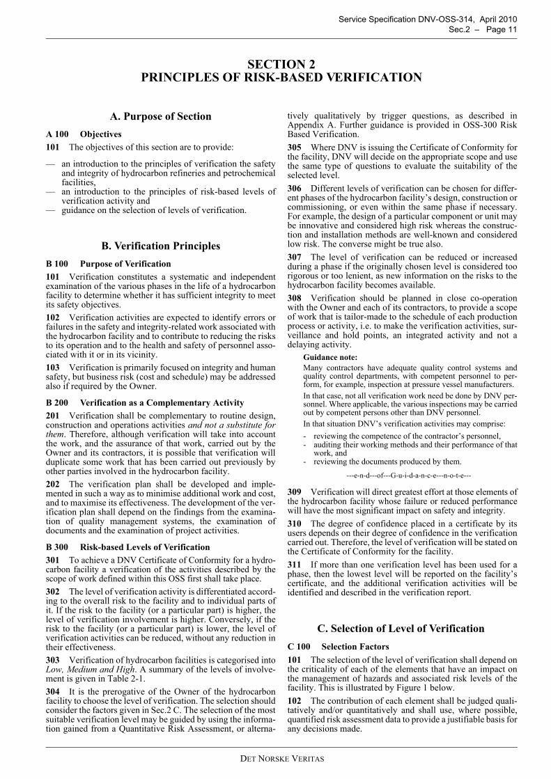
B 300 Risk-based Levels of Verification301 To achieve a DNV Certificate of Conformity for a hydro-carbon facility a verification of the activities described by thescope of work defined within this OSS first shall take place.302 The level of verification activity is differentiated accord-ing to the overall risk to the facility and to individual parts ofit. If the risk to the facility (or a particular part) is higher, thelevel of verification involvement is higher. Conversely, if therisk to the facility (or a particular part) is lower, the level ofverification activities can be reduced, without any reduction intheir effectiveness.303 Verification of hydrocarbon facilities is categorised intoLow, Medium and High. A summary of the levels of involve-ment is given in Table 2-1.304 It is the prerogative of the Owner of the hydrocarbonfacility to choose the level of verification. The selection shouldconsider the factors given in Sec.2 C. The selection of the mostsuitable verification level may be guided by using the informa-tion gained from a Quantitative Risk Assessment, or alterna-
tively qualitatively by trigger questions, as described inAppendix A. Further guidance is provided in OSS-300 RiskBased Verification.305 Where DNV is issuing the Certificate of Conformity forthe facility, DNV will decide on the appropriate scope and usethe same type of questions to evaluate the suitability of theselected level.306 Different levels of verification can be chosen for differ-ent phases of the hydrocarbon facility’s design, construction orcommissioning, or even within the same phase if necessary.For example, the design of a particular component or unit maybe innovative and considered high risk whereas the construc-tion and installation methods are well-known and consideredlow risk. The converse might be true also.307 The level of verification can be reduced or increasedduring a phase if the originally chosen level is considered toorigorous or too lenient, as new information on the risks to thehydrocarbon facility becomes available.308 Verification should be planned in close co-operationwith the Owner and each of its contractors, to provide a scopeof work that is tailor-made to the schedule of each productionprocess or activity, i.e. to make the verification activities, sur-veillance and hold points, an integrated activity and not adelaying activity.
Guidance note:Many contractors have adequate quality control systems andquality control departments, with competent personnel to per-form, for example, inspection at pressure vessel manufacturers.In that case, not all verification work need be done by DNV per-sonnel. Where applicable, the various inspections may be carriedout by competent persons other than DNV personnel.In that situation DNV’s verification activities may comprise:- reviewing the competence of the contractor’s personnel,- auditing their working methods and their performance of that
work, and- reviewing the documents produced by them.
---e-n-d---of---G-u-i-d-a-n-c-e---n-o-t-e---
309 Verification will direct greatest effort at those elements ofthe hydrocarbon facility whose failure or reduced performancewill have the most significant impact on safety and integrity. 310 The degree of confidence placed in a certificate by itsusers depends on their degree of confidence in the verificationcarried out. Therefore, the level of verification will be stated onthe Certificate of Conformity for the facility.311 If more than one verification level has been used for aphase, then the lowest level will be reported on the facility’scertificate, and the additional verification activities will beidentified and described in the verification report.
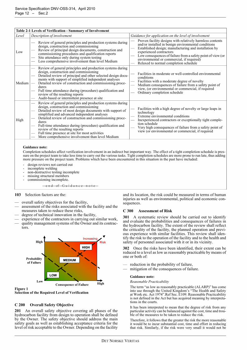
C. Selection of Level of Verification C 100 Selection Factors101 The selection of the level of verification shall depend onthe criticality of each of the elements that have an impact onthe management of hazards and associated risk levels of thefacility. This is illustrated by Figure 1 below.102 The contribution of each element shall be judged quali-tatively and/or quantitatively and shall use, where possible,quantified risk assessment data to provide a justifiable basis forany decisions made.
DET NORSKE VERITAS
Service Specification DNV-OSS-314, April 2010 Page 12 – Sec.2
103 Selection factors are the:
— overall safety objectives for the facility,— assessment of the risks associated with the facility and the
measures taken to reduce these risks,— degree of technical innovation in the facility,— experience of the contractors in carrying out similar work,— quality management systems of the Owner and its contrac-
tors.
Figure 1 Selection of the Required Level of Verification
C 200 Overall Safety Objective201 An overall safety objective covering all phases of thehydrocarbon facility from design to operation shall be definedby the Owner. The safety objective should address the mainsafety goals as well as establishing acceptance criteria for thelevel of risk acceptable to the Owner. Depending on the facility
and its location, the risk could be measured in terms of humaninjuries as well as environmental, political and economic con-sequences.
C 300 Assessment of Risk301 A systematic review should be carried out to identifyand evaluate the probabilities and consequences of failures inthe hydrocarbon facility. The extent of the review shall reflectthe criticality of the facility, the planned operation and previ-ous experience with similar facilities. This review shall iden-tify the risk to the operation of the facility and to the health andsafety of personnel associated with it or in its vicinity. 302 Once the risks have been identified, their extent can bereduced to a level as low as reasonably practicable by means ofone or both of:
— reduction in the probability of failure,— mitigation of the consequences of failure.
Guidance note:Reasonable PracticabilityThe term “as low as reasonably practicable (ALARP)” has comeinto use through the United Kingdom’s “The Health and Safetyat Work etc. Act 1974”.Ref Sec. E109. Reasonable Practicabilityis not defined in the Act but has acquired meaning by interpreta-tions in the courts.It has been interpreted to mean that the degree of risk from anyparticular activity can be balanced against the cost, time and trou-ble of the measures to be taken to reduce the risk.Therefore, it follows that the greater the risk the more reasonableit would be to incur substantial cost, time and effort in reducingthat risk. Similarly, if the risk were very small it would not be
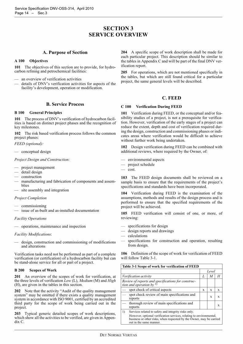
Table 2-1 Levels of Verification - Summary of InvolvementLevel Description of involvement Guidance for application on the level of involvement
Low
— Review of general principles and production systems during design, construction and commissioning
— Review of principal design documents, construction and commissioning procedures and qualification reports
— Site attendance only during system testing— Less comprehensive involvement than level Medium
— Proven facility designs with relatively harmless contents and/or installed in benign environmental conditions
— Established design; manufacturing and installation by experienced contractors
— Low consequences of failure from a safety point of view (or environmental or commercial, if required)
— Relaxed to normal completion schedule
Medium
— Review of general principles and production systems during design, construction and commissioning
— Detailed review of principal and other selected design docu-ments with support of simplified independent analyses
— Detailed review of construction and commissioning proce-dures
— Full time attendance during (procedure) qualification and review of the resulting reports
— Audit-based or intermittent presence at site
— Facilities in moderate or well-controlled environmental conditions
— Facilities with a moderate degree of novelty— Medium consequences of failure from a safety point of
view, (or environmental or commercial, if required — Ordinary completion schedule
High
— Review of general principles and production systems during design, construction and commissioning
— Detailed review of most design documents with support of simplified and advanced independent analyses
— Detailed review of construction and commissioning proce-dures
— Full-time attendance during (procedure) qualification and review of the resulting reports
— Full time presence at site for most activities— More comprehensive involvement than level Medium
— Facilities with a high degree of novelty or large leaps in technology
— Extreme environmental conditions— Inexperienced contractors or exceptionally tight comple-
tion schedule— Very high consequences of failure from a safety point of
view (or environmental or commercial, if required
Guidance note:Completion schedules affect verification involvement in an indirect but important way. The effect of a tight completion schedule is pres-sure on the project team to take less time to carry out the various tasks. Tight completion schedules are more prone to run late, thus addingmore pressure on the project team. Problems which have been encountered in this situation in the past have included:- design reviews not carried out- incomplete welding- non-destructive testing incomplete- missing structural members- commissioning incomplete.
---e-n-d---of---G-u-i-d-a-n-c-e---n-o-t-e---
Consequence of Failure
Probability of Failure
Low
High
High
IInnccrreeaassiinngg RRiisskk
MMEEDDIIUUMM
HHIIGGHH
LLOOWW
DET NORSKE VERITAS

Service Specification DNV-OSS-314, April 2010 Sec.2 – Page 13
reasonable to expect great expense or effort to be incurred inreducing it.Further guidance on the principles and application of ALARPmay be obtained from the United Kingdom’s Heath and SafetyExecutive web-site at http://www.hse.gov.uk/risk/theory/alarp.htm (July 2009).
---e-n-d---of---G-u-i-d-a-n-c-e---n-o-t-e---
303 The result of the systematic review of these risks ismeasured against the safety objectives and used in the selec-tion of the appropriate verification activity level.
C 400 Technical Innovation and Contractor Experience401 The degree of technical innovation in the hydrocarbonfacility system shall be considered. Risks to the facility arelikely to be greater for a facility with a high degree of technicalinnovation than with a facility designed, manufactured andinstalled to well-known criteria in well-known locations.402 Similarly, the degree of risk to the facility should be con-sidered where contractors are inexperienced or the workschedule is tight.403 Factors to be considered in the selection of the appropri-ate verification level include:
— degree of difficulty in achieving technical requirements,— knowledge of similar facilities,— knowledge of contractors’ general experience,— knowledge of contractors’ experience in similar work.
C 500 Quality Management Systems501 Adequate quality management systems shall be imple-mented to ensure that gross errors in the work for facilitydesign, construction and operations are limited.502 Factors to be considered when evaluating the adequacyof the quality management system include:
— whether or not an ISO 9001, ref. Sec.1 E or equivalent cer-tified system is in place
— results from external audits— results from internal audits— experience with contractors’ previous work— project work-force familiarity with the quality manage-
ment system, e.g. has there been a rapid expansion of thework force or are all parties of a joint venture familiar withthe same system.
D. CommunicationsD 100 Notification of Verification Level101 An assessment of the required level of verification for aproject should be made by the Owner before preparing tenderdocuments for design and construction activities. The Owner canthen specify this level in Invitations to Tender. This will givecontractors clear guidance and reference when estimating theextent and cost of efforts associated with verification activities.
102 The required level of verification can be assessed by theOwner using this OSS. However, if the Owner requires theContractor to carry out this assessment as part of his responseto an Invitation to Tender the Owner should provide the neces-sary information to enable the Contractor to carry out thiswork. This information should include overall safety objec-tives for the hydrocarbon facility as well as particulars, such astemperatures, pressures, contents and environmental criteria,commonly contained in a design brief.
D 200 Obligations201 To achieve the purpose and benefits of verification theinvolved parties shall be mutually obliged to share and actupon all relevant information pertaining to the verificationscope.202 The Owner shall be obliged to:
— Inform DNV about the basis for selecting the level of ver-ification and the investigations and assumptions made inthis context.
— Give DNV full access to all information concerning theverification scope for the hydrocarbon facility and ensurethat clauses to this effect are included in contracts for par-ties acting on behalf of the Owner and parties providingproducts, processes and services covered by the verifica-tion scope. If information is proprietary and not available,exclusion from verification shall be mutually agreed withDNV.
— Ensure that DNV is involved in the handling of deviationsfrom specified requirements within the verification scope.
— Act upon information provided by DNV with respect toevents or circumstances that may jeopardise the safety orintegrity of the facility and/or the purpose and benefit ofverification
— Ensure that the Safety Objective established for the facilityis known and pursued by parties acting on behalf of theOwner and parties providing products, processes and serv-ices covered by the verification scope.
203 Second parties shall be obliged to:
— Perform their assigned tasks in accordance with the safetyobjectives established for the project.
— Provide the Owner and DNV with all relevant informationpertaining to the verification scope.
204 DNV will be obliged to:
— Inform the Owner if, in the opinion of DNV, the basis forselecting the level of verification or the assumptions madein this respect are found to be in error or assessed incor-rectly.
— Inform the Owner of events or circumstances that, in theopinion of DNV, may jeopardise the safety or integrity ofthe facility and/or the purpose and benefit of verification.
— Effectively perform all verification work and adjust thelevel of involvement according to the actual performanceof parties providing products, processes and services cov-ered by the verification scope.
DET NORSKE VERITAS
Service Specification DNV-OSS-314, April 2010 Page 14 – Sec.3
SECTION 3SERVICE OVERVIEW
A. Purpose of Section
A 100 Objectives101 The objectives of this section are to provide, for hydro-carbon refining and petrochemical facilities:
— an overview of verification activities— details of DNV’s verification activities for aspects of the
facility’s development, operation or modification.
B. Service Process
B 100 General Principles101 The process of DNV’s verification of hydrocarbon facil-ities is based on distinct project phases and the recognition ofkey milestones.102 The risk based verification process follows the commonproject phases:FEED (optional):
— conceptual design
Project Design and Construction:
— project management— detail design— construction— manufacturing and fabrication of components and assem-
blies— site assembly and integration
Project Completion
— commissioning— issue of as-built and as-installed documentation
Facility Operations
— operations, maintenance and inspection
Facility Modifications:
— design, construction and commissioning of modificationsand alterations
Verification tasks need not be performed as part of a completeverification (or certification) of a hydrocarbon facility but canbe stand-alone service for all or part of a project.
B 200 Scopes of Work201 An overview of the scopes of work for verification, atthe three levels of verification Low (L), Medium (M) and High(H), are given in the tables in this section.202 Note that the activity “Audit of the quality managementsystem” may be omitted if there exists a quality managementsystem in accordance with ISO 9001, certified by an accreditedthird party for the scope of work being carried out in theproject.203 Typical generic detailed scopes of work descriptions,which show all the activities to be verified, are given in Appen-dix C.
204 A specific scope of work description shall be made foreach particular project. This description should be similar tothe tables in Appendix C and will be part of the final DNV ver-ification report.205 For operations, which are not mentioned specifically inthe tables, but which are still found critical for a particularproject, the same general levels will be described.
C. FEED
C 100 Verification During FEED101 Verification during FEED, or the conceptual and/or fea-sibility studies of a project, is not a prerequisite for verifica-tion. However, verification of the early stages of a project canreduce the extent, depth and cost of verification required dur-ing the design, construction and commissioning phases or indi-cates areas where verification would be difficult to achievewithout further work being undertaken.102 Design verification during FEED can be combined withadditional reviews, where required by the Owner, of:
— environmental aspects— project schedule— cost.
103 The FEED design documents shall be reviewed on asample basis to ensure that the requirements of the project’sspecifications and standards have been incorporated.104 Verification during FEED is the examination of theassumptions, methods and results of the design process and isperformed to ensure that the specified requirements of theproject will be achieved.105 FEED verification will consist of one, or more, ofreviewing:
— specifications for design— design reports and drawings— calculations— specifications for construction and operation, resulting
from design.
106 Definition of the scope of work for verification of FEEDwill follow Table 3-1.
Table 3-1 Scope of work for verification of FEEDLevel
Verification activity L M HReview of reports and specifications for construc-tion and operation by 1)
— spot check of critical aspects x x x— spot check review of main specifications and
reports x x
— thorough review of main specifications and reports x
1) Services related to safety and integrity risks only.However, optional verification services, relating to environmental, business or other risks, when requested by the Owner, may be carried out in the same manner.
DET NORSKE VERITAS
Service Specification DNV-OSS-314, April 2010 Sec.3 – Page 15
D. Project Design, Construction and Commissioning
D 100 General101 All design, construction and commissioning aspects, rel-evant to hydrocarbon facility safety and integrity, shall be cov-ered by the verification process.102 Verification describes the individual activities under-taken by DNV at the various stages of the design, constructionand commissioning of the hydrocarbon facility to confirm thatthe safety and integrity requirements of the Owner have beenfulfilled.
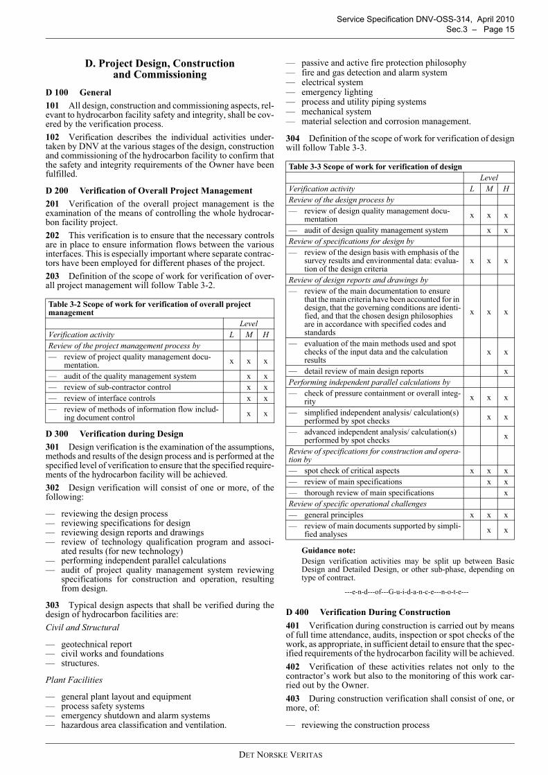
D 200 Verification of Overall Project Management201 Verification of the overall project management is theexamination of the means of controlling the whole hydrocar-bon facility project.202 This verification is to ensure that the necessary controlsare in place to ensure information flows between the variousinterfaces. This is especially important where separate contrac-tors have been employed for different phases of the project.203 Definition of the scope of work for verification of over-all project management will follow Table 3-2.
D 300 Verification during Design301 Design verification is the examination of the assumptions,methods and results of the design process and is performed at thespecified level of verification to ensure that the specified require-ments of the hydrocarbon facility will be achieved.302 Design verification will consist of one or more, of thefollowing:
— reviewing the design process— reviewing specifications for design— reviewing design reports and drawings— review of technology qualification program and associ-
ated results (for new technology)— performing independent parallel calculations— audit of project quality management system reviewing
specifications for construction and operation, resultingfrom design.
303 Typical design aspects that shall be verified during thedesign of hydrocarbon facilities are:Civil and Structural
— geotechnical report— civil works and foundations— structures.
Plant Facilities
— general plant layout and equipment— process safety systems— emergency shutdown and alarm systems— hazardous area classification and ventilation.
— passive and active fire protection philosophy— fire and gas detection and alarm system— electrical system— emergency lighting— process and utility piping systems— mechanical system— material selection and corrosion management.
304 Definition of the scope of work for verification of designwill follow Table 3-3.
Guidance note:Design verification activities may be split up between BasicDesign and Detailed Design, or other sub-phase, depending ontype of contract.
---e-n-d---of---G-u-i-d-a-n-c-e---n-o-t-e---
D 400 Verification During Construction401 Verification during construction is carried out by meansof full time attendance, audits, inspection or spot checks of thework, as appropriate, in sufficient detail to ensure that the spec-ified requirements of the hydrocarbon facility will be achieved.402 Verification of these activities relates not only to thecontractor’s work but also to the monitoring of this work car-ried out by the Owner.403 During construction verification shall consist of one, ormore, of:
— reviewing the construction process
Table 3-2 Scope of work for verification of overall project management
LevelVerification activity L M HReview of the project management process by— review of project quality management docu-
mentation. x x x
— audit of the quality management system x x— review of sub-contractor control x x— review of interface controls x x— review of methods of information flow includ-
ing document control x x
Table 3-3 Scope of work for verification of design Level
Verification activity L M HReview of the design process by— review of design quality management docu-
mentation x x x
— audit of design quality management system x xReview of specifications for design by— review of the design basis with emphasis of the
survey results and environmental data: evalua-tion of the design criteria
x x x
Review of design reports and drawings by— review of the main documentation to ensure
that the main criteria have been accounted for in design, that the governing conditions are identi-fied, and that the chosen design philosophies are in accordance with specified codes and standards
x x x
— evaluation of the main methods used and spot checks of the input data and the calculation results
x x
— detail review of main design reports xPerforming independent parallel calculations by— check of pressure containment or overall integ-
rity x x x
— simplified independent analysis/ calculation(s) performed by spot checks x x
— advanced independent analysis/ calculation(s) performed by spot checks x
Review of specifications for construction and opera-tion by— spot check of critical aspects x x x— review of main specifications x x— thorough review of main specifications xReview of specific operational challenges— general principles x x x— review of main documents supported by simpli-
fied analyses x x
DET NORSKE VERITAS
Service Specification DNV-OSS-314, April 2010 Page 16 – Sec.3
— reviewing construction procedures— reviewing qualification processes and results— surveillance during construction activities— reviewing final documentation.
404 Typical site activities to be verified during constructionand up to mechanical completion are:Civil and Structural
— civil and structural works— equipment supports— storage tank foundations— structural fire protection.
Mechanical
— mechanical equipment installation— process piping installation— welding procedures qualification and control— welders’ qualification and welders’ identification control— welding quality records— non-destructive testing methods and reports— pressure and leak tests of process piping system— set pressures for relief valves.
Electrical and Instrumentation
— electrical equipment and instrumentation in hazardousareas
— insulation resistance and continuity tests on equipmentand cables
— equipment earthing— electrical installation work— relevant tests of electrical and instrumentation equipment,
especially calibration of instruments and setting of protec-tive devices if any.
Common
— material control and identification system— final inspection reports of procured items.
405 The documents that should be produced in the projectand submitted for review typically are:
— construction procedures and method statements; includingtest requirements, test procedures and acceptance criteria,repairs, personnel qualification records, etc.
— material specifications and data sheets— drawings— quality plans including Inspection and test plans— welding procedure specifications and welding procedure
qualification record— NDT procedures.
406 The final documentation to be submitted after construc-tion that should reflect the ‘as-built’ status of the facility,should include but not be limited to:
— construction test records; visual, NDT, test samples,dimensional, heat treatment, etc.
— hydrostatic test reports— as-built drawings.
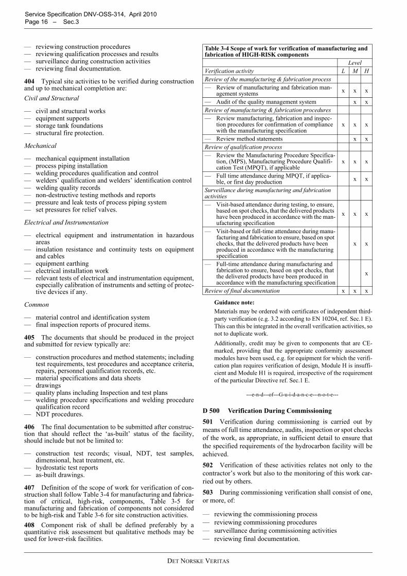
407 Definition of the scope of work for verification of con-struction shall follow Table 3-4 for manufacturing and fabrica-tion of critical, high-risk, components, Table 3-5 formanufacturing and fabrication of components not consideredto be high-risk and Table 3-6 for site construction activities.408 Component risk of shall be defined preferably by aquantitative risk assessment but qualitative methods may beused for lower-risk facilities.
Guidance note:Materials may be ordered with certificates of independent third-party verification (e.g. 3.2 according to EN 10204, ref. Sec.1 E).This can this be integrated in the overall verification activities, sonot to duplicate work.Additionally, credit may be given to components that are CE-marked, providing that the appropriate conformity assessmentmodules have been used, e.g. for equipment for which the verifi-cation plan requires verification of design, Module H is insuffi-cient and Module H1 is required, irrespective of the requirementof the particular Directive ref. Sec.1 E.
---e-n-d---of---G-u-i-d-a-n-c-e---n-o-t-e---
D 500 Verification During Commissioning501 Verification during commissioning is carried out bymeans of full time attendance, audits, inspection or spot checksof the work, as appropriate, in sufficient detail to ensure thatthe specified requirements of the hydrocarbon facility will beachieved.502 Verification of these activities relates not only to thecontractor’s work but also to the monitoring of this work car-ried out by others.503 During commissioning verification shall consist of one,or more, of:
— reviewing the commissioning process— reviewing commissioning procedures— surveillance during commissioning activities— reviewing final documentation.
Table 3-4 Scope of work for verification of manufacturing and fabrication of HIGH-RISK components
LevelVerification activity L M HReview of the manufacturing & fabrication process— Review of manufacturing and fabrication man-
agement systems x x x
— Audit of the quality management system x xReview of manufacturing & fabrication procedures— Review manufacturing, fabrication and inspec-
tion procedures for confirmation of compliance with the manufacturing specification
x x x
— Review method statements x xReview of qualification process— Review the Manufacturing Procedure Specifica-
tion, (MPS), Manufacturing Procedure Qualifi-cation Test (MPQT), if applicable
x x x
— Full time attendance during MPQT, if applica-ble, or first day production x x
Surveillance during manufacturing and fabrication activities— Visit-based attendance during testing, to ensure,
based on spot checks, that the delivered products have been produced in accordance with the man-ufacturing specification
x x x
— Visit-based or full-time attendance during manu-facturing and fabrication to ensure, based on spot checks, that the delivered products have been produced in accordance with the manufacturing specification
x x
— Full-time attendance during manufacturing and fabrication to ensure, based on spot checks, that the delivered products have been produced in accordance with the manufacturing specification
x
Review of final documentation x x x
DET NORSKE VERITAS
Service Specification DNV-OSS-314, April 2010 Sec.3 – Page 17
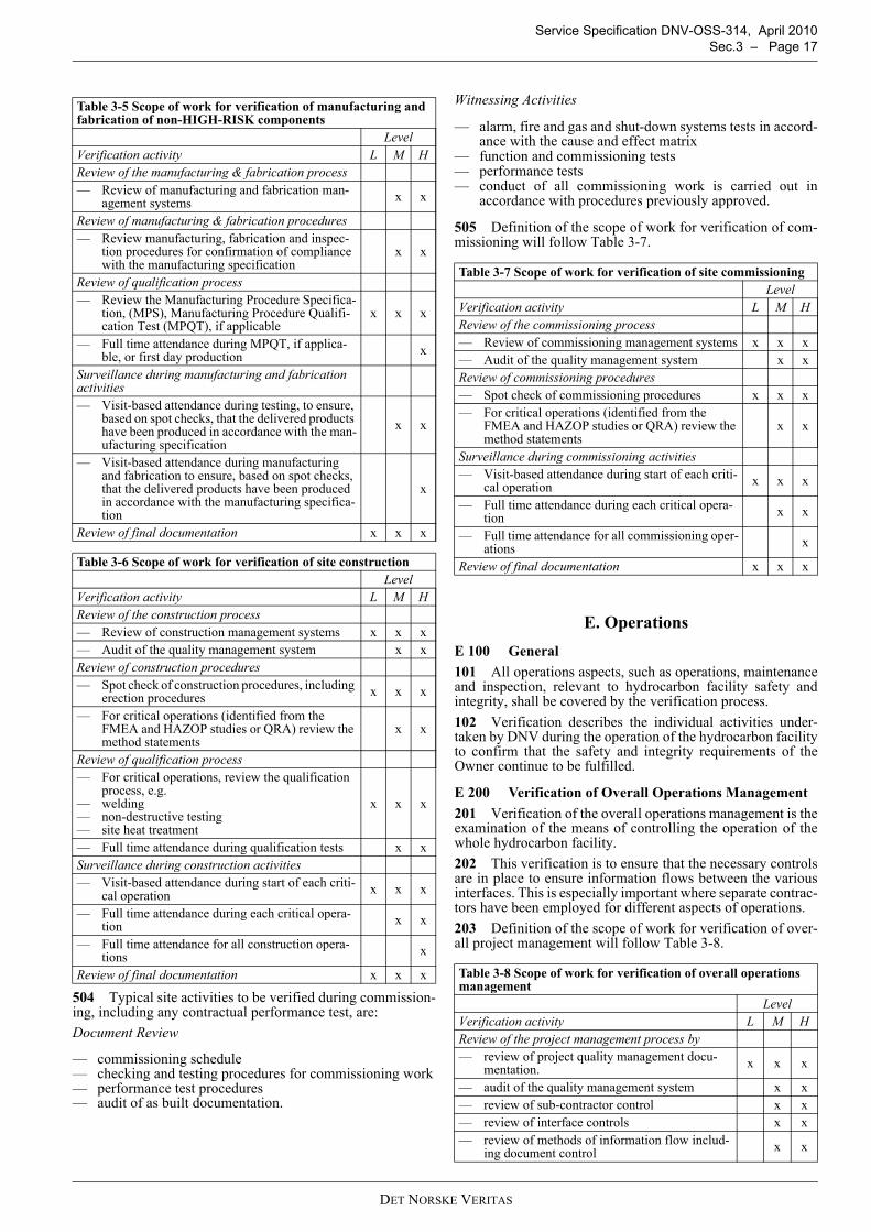
504 Typical site activities to be verified during commission-ing, including any contractual performance test, are:Document Review
— commissioning schedule— checking and testing procedures for commissioning work— performance test procedures— audit of as built documentation.
Witnessing Activities
— alarm, fire and gas and shut-down systems tests in accord-ance with the cause and effect matrix
— function and commissioning tests— performance tests— conduct of all commissioning work is carried out in
accordance with procedures previously approved.
505 Definition of the scope of work for verification of com-missioning will follow Table 3-7.
E. OperationsE 100 General101 All operations aspects, such as operations, maintenanceand inspection, relevant to hydrocarbon facility safety andintegrity, shall be covered by the verification process.102 Verification describes the individual activities under-taken by DNV during the operation of the hydrocarbon facilityto confirm that the safety and integrity requirements of theOwner continue to be fulfilled.
E 200 Verification of Overall Operations Management201 Verification of the overall operations management is theexamination of the means of controlling the operation of thewhole hydrocarbon facility.202 This verification is to ensure that the necessary controlsare in place to ensure information flows between the variousinterfaces. This is especially important where separate contrac-tors have been employed for different aspects of operations.203 Definition of the scope of work for verification of over-all project management will follow Table 3-8.
Table 3-5 Scope of work for verification of manufacturing and fabrication of non-HIGH-RISK components
LevelVerification activity L M HReview of the manufacturing & fabrication process— Review of manufacturing and fabrication man-
agement systems x x
Review of manufacturing & fabrication procedures— Review manufacturing, fabrication and inspec-
tion procedures for confirmation of compliance with the manufacturing specification
x x
Review of qualification process— Review the Manufacturing Procedure Specifica-
tion, (MPS), Manufacturing Procedure Qualifi-cation Test (MPQT), if applicable
x x x
— Full time attendance during MPQT, if applica-ble, or first day production x
Surveillance during manufacturing and fabrication activities— Visit-based attendance during testing, to ensure,
based on spot checks, that the delivered products have been produced in accordance with the man-ufacturing specification
x x
— Visit-based attendance during manufacturing and fabrication to ensure, based on spot checks, that the delivered products have been produced in accordance with the manufacturing specifica-tion
x
Review of final documentation x x x
Table 3-6 Scope of work for verification of site constructionLevel
Verification activity L M HReview of the construction process— Review of construction management systems x x x— Audit of the quality management system x xReview of construction procedures— Spot check of construction procedures, including
erection procedures x x x
— For critical operations (identified from the FMEA and HAZOP studies or QRA) review the method statements
x x
Review of qualification process— For critical operations, review the qualification
process, e.g.— welding— non-destructive testing— site heat treatment
x x x
— Full time attendance during qualification tests x xSurveillance during construction activities— Visit-based attendance during start of each criti-
cal operation x x x
— Full time attendance during each critical opera-tion x x
— Full time attendance for all construction opera-tions x
Review of final documentation x x x
Table 3-7 Scope of work for verification of site commissioningLevel
Verification activity L M HReview of the commissioning process— Review of commissioning management systems x x x— Audit of the quality management system x xReview of commissioning procedures— Spot check of commissioning procedures x x x— For critical operations (identified from the
FMEA and HAZOP studies or QRA) review the method statements
x x
Surveillance during commissioning activities— Visit-based attendance during start of each criti-
cal operation x x x
— Full time attendance during each critical opera-tion x x
— Full time attendance for all commissioning oper-ations x
Review of final documentation x x x
Table 3-8 Scope of work for verification of overall operations management
LevelVerification activity L M HReview of the project management process by— review of project quality management docu-
mentation. x x x
— audit of the quality management system x x— review of sub-contractor control x x— review of interface controls x x— review of methods of information flow includ-
ing document control x x
DET NORSKE VERITAS
Service Specification DNV-OSS-314, April 2010 Page 18 – Sec.3
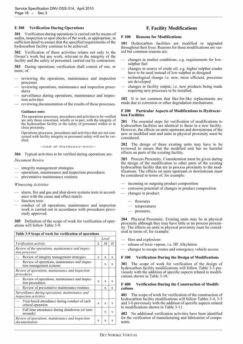
E 300 Verification During Operations301 Verification during operations is carried out by means ofaudits, inspection or spot checks of the work, as appropriate, insufficient detail to ensure that the specified requirements of thehydrocarbon facility continue to be achieved.302 Verification of these activities relates not only to theOwner’s work but any work, relevant to the integrity of thefacility and the safety of personnel, carried out by contractors.303 During operations verification shall consist of one, ormore, of:
— reviewing the operations, maintenance and inspectionprocesses
— reviewing operations, maintenance and inspection proce-dures
— surveillance during operations, maintenance and inspec-tion activities
— reviewing documentation of the results of these processes.
Guidance note:The operations processes, procedures and activities to be verifiedare only those concerned, wholly or in part, with the integrity ofthe hydrocarbon facility or the safety of personnel within or inclose proximity.Operations processes, procedures and activities that are not con-cerned with facility integrity or personnel safety will not be ver-ified.
---e-n-d---of---G-u-i-d-a-n-c-e---n-o-t-e---
304 Typical activities to be verified during operations are:Document Review
— integrity management strategies— operations, maintenance and inspection procedures— preventative maintenance routines
Witnessing Activities
— alarm, fire and gas and shut-down systems tests in accord-ance with the cause and effect matrix
— function tests— conduct of all operations, maintenance and inspection
work is carried out in accordance with procedures previ-ously approved.
305 Definition of the scope of work for verification of oper-ations will follow Table 3-9.
F. Facility Modifications
F 100 Reasons for Modifications101 Hydrocarbon facilities are modified or upgradedthroughout their lives. Reasons for these modifications are var-ied but common reasons are:
— changes in market conditions, e.g. requirements for low-sulphur fuel
— changes in source of crude oil, e.g. higher sulphur crudeshave to be used instead of low-sulphur as designed
— technological change i.e. new, more efficient, processesare developed
— changes in facility output, i.e. new products being maderequiring new processes to be installed.
102 It is not common that like-for-like replacements aremade due to corrosion or other degradation mechanisms.
F 200 Particular Aspects of Modifications to Hydrocar-bon Facilities201 The essential steps for verification of modifications tohydrocarbon facilities are identical to those in a new facility.However, the effects on units upstream and downstream of thenew or modified unit and units in physical proximity must beconsidered.202 The design of these existing units may have to bereviewed to ensure that the modified unit has no harmfuleffects on parts of the existing facility.203 Process Proximity. Consideration must be given duringthe design of the modification to other parts of the existinghydrocarbon facility that are in process proximity to the mod-ifications. The effects on units upstream or downstream mustbe considered in terms of, for example:
— incoming or outgoing product composition— corrosion potential of changes in product composition— changes in product:
— flowrates— temperatures— pressures.
204 Physical Proximity. Existing units may be in physicalproximity although they may have little or no process proxim-ity. The effects on units in physical proximity must be consid-ered in terms of, for example:
— fires and explosions— release of toxic vapour, i.e. HF Alkylation— changes to escape routes and emergency vehicle access.
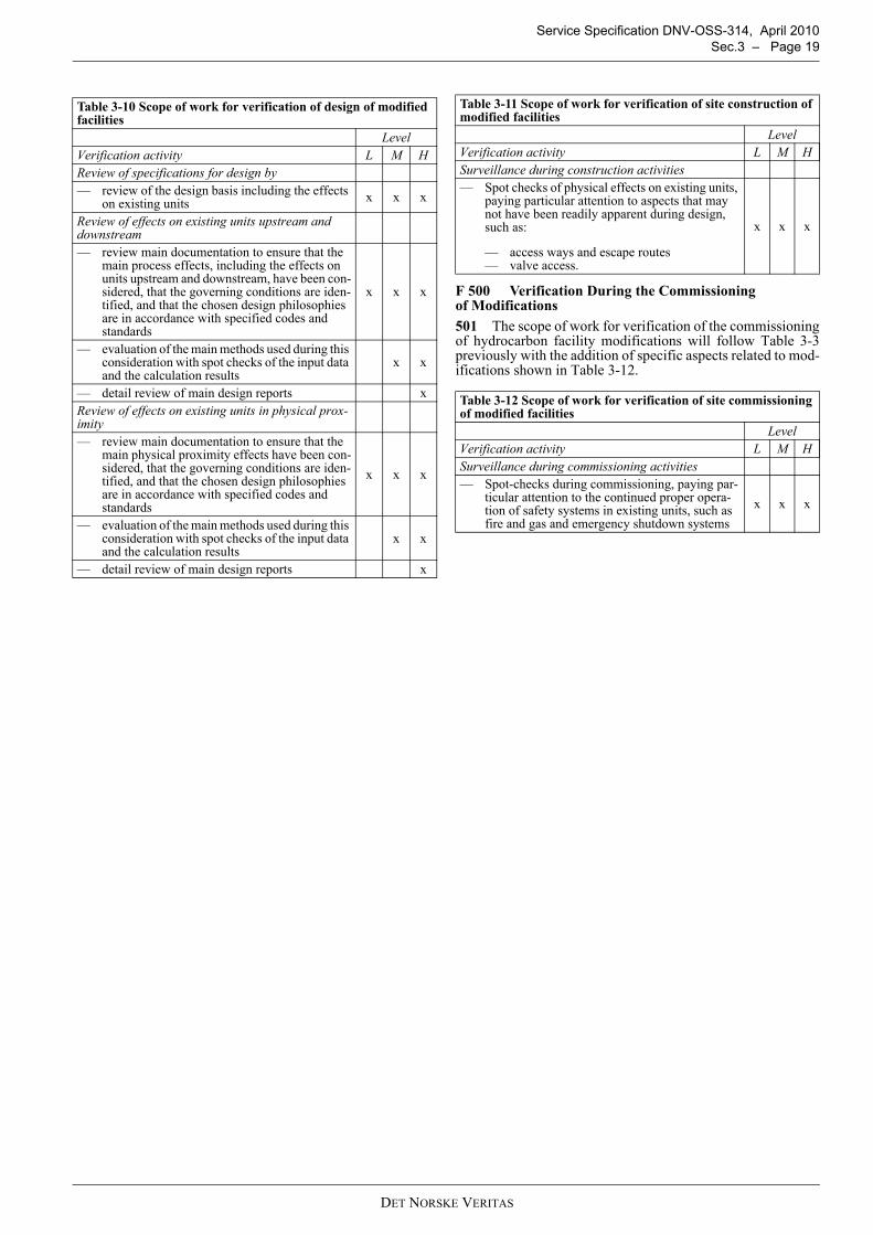
F 300 Verification During the Design of Modifications301 The scope of work for verification of the design ofhydrocarbon facility modifications will follow Table 3-3 pre-viously with the addition of specific aspects related to modifi-cations shown in Table 3-10.
F 400 Verification During the Construction of Modifi-cations401 The scope of work for verification of the construction ofhydrocarbon facility modifications will follow Tables 3-4, 3-5and 3-6 previously with the addition of specific aspects relatedto modifications shown in Table 3-11.402 No additional verification activities have been identifiedfor the verification of manufacturing and fabrication of compo-nents.
Table 3-9 Scope of work for verification of operationsLevel
Verification activity L M HReview of the operations, maintenance and inspec-tion processes— Review of integrity management strategies x x x— Review of operations, maintenance and inspec-
tion management systems x x
Review of operations, maintenance and inspection procedures— Review of operations, maintenance and inspec-
tion procedures x x x
— Review of preventative maintenance routines x xSurveillance during operations, maintenance and inspection activities— Visit-based attendance during conduct of each
critical operation x x x
— Full time attendance during shutdowns (or turn-arounds) x x
Review of operations, maintenance and inspection documentation x x x
DET NORSKE VERITAS
Service Specification DNV-OSS-314, April 2010 Sec.3 – Page 19
F 500 Verification During the Commissioning of Modifications501 The scope of work for verification of the commissioningof hydrocarbon facility modifications will follow Table 3-3previously with the addition of specific aspects related to mod-ifications shown in Table 3-12.
Table 3-10 Scope of work for verification of design of modified facilities
LevelVerification activity L M HReview of specifications for design by— review of the design basis including the effects
on existing units x x x
Review of effects on existing units upstream and downstream— review main documentation to ensure that the
main process effects, including the effects on units upstream and downstream, have been con-sidered, that the governing conditions are iden-tified, and that the chosen design philosophies are in accordance with specified codes and standards
x x x
— evaluation of the main methods used during this consideration with spot checks of the input data and the calculation results
x x
— detail review of main design reports xReview of effects on existing units in physical prox-imity— review main documentation to ensure that the
main physical proximity effects have been con-sidered, that the governing conditions are iden-tified, and that the chosen design philosophies are in accordance with specified codes and standards
x x x
— evaluation of the main methods used during this consideration with spot checks of the input data and the calculation results
x x
— detail review of main design reports x
Table 3-11 Scope of work for verification of site construction of modified facilities
LevelVerification activity L M HSurveillance during construction activities— Spot checks of physical effects on existing units,
paying particular attention to aspects that may not have been readily apparent during design, such as:
— access ways and escape routes— valve access.
x x x
Table 3-12 Scope of work for verification of site commissioning of modified facilities
LevelVerification activity L M HSurveillance during commissioning activities— Spot-checks during commissioning, paying par-
ticular attention to the continued proper opera-tion of safety systems in existing units, such as fire and gas and emergency shutdown systems
x x x
DET NORSKE VERITAS
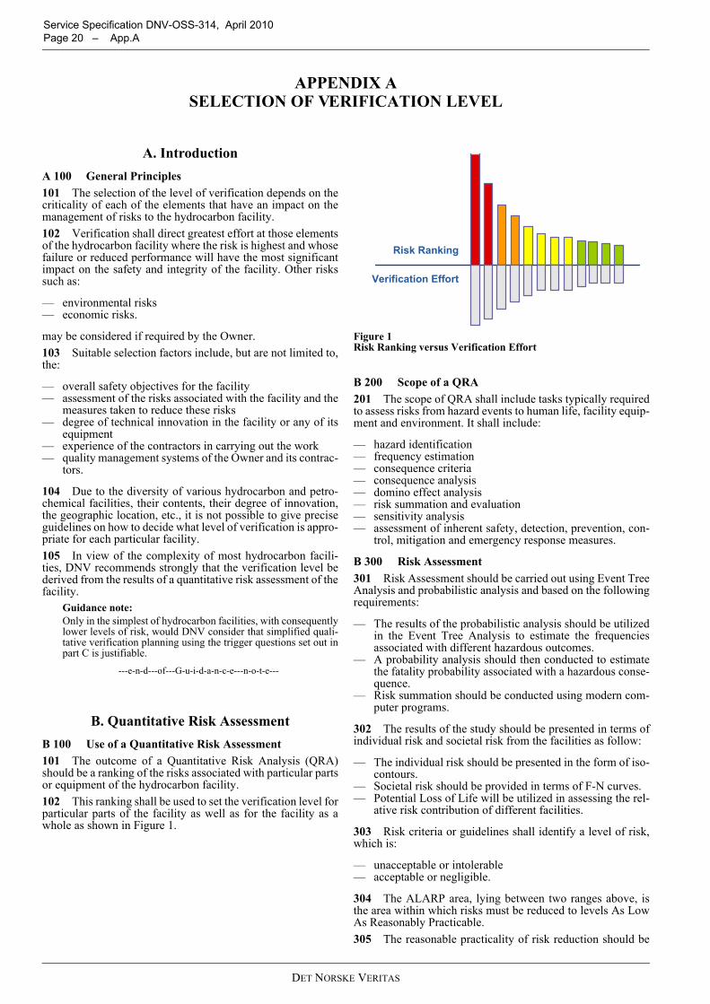
Service Specification DNV-OSS-314, April 2010 Page 20 – App.A
APPENDIX A SELECTION OF VERIFICATION LEVEL
A. IntroductionA 100 General Principles101 The selection of the level of verification depends on thecriticality of each of the elements that have an impact on themanagement of risks to the hydrocarbon facility.102 Verification shall direct greatest effort at those elementsof the hydrocarbon facility where the risk is highest and whosefailure or reduced performance will have the most significantimpact on the safety and integrity of the facility. Other riskssuch as:
— environmental risks— economic risks.
may be considered if required by the Owner.103 Suitable selection factors include, but are not limited to,the:
— overall safety objectives for the facility— assessment of the risks associated with the facility and the
measures taken to reduce these risks— degree of technical innovation in the facility or any of its
equipment— experience of the contractors in carrying out the work— quality management systems of the Owner and its contrac-
tors.
104 Due to the diversity of various hydrocarbon and petro-chemical facilities, their contents, their degree of innovation,the geographic location, etc., it is not possible to give preciseguidelines on how to decide what level of verification is appro-priate for each particular facility.105 In view of the complexity of most hydrocarbon facili-ties, DNV recommends strongly that the verification level bederived from the results of a quantitative risk assessment of thefacility.
Guidance note:Only in the simplest of hydrocarbon facilities, with consequentlylower levels of risk, would DNV consider that simplified quali-tative verification planning using the trigger questions set out inpart C is justifiable.
---e-n-d---of---G-u-i-d-a-n-c-e---n-o-t-e---
B. Quantitative Risk AssessmentB 100 Use of a Quantitative Risk Assessment101 The outcome of a Quantitative Risk Analysis (QRA)should be a ranking of the risks associated with particular partsor equipment of the hydrocarbon facility.102 This ranking shall be used to set the verification level forparticular parts of the facility as well as for the facility as awhole as shown in Figure 1.
Figure 1 Risk Ranking versus Verification Effort
B 200 Scope of a QRA201 The scope of QRA shall include tasks typically requiredto assess risks from hazard events to human life, facility equip-ment and environment. It shall include:
— hazard identification— frequency estimation— consequence criteria— consequence analysis— domino effect analysis— risk summation and evaluation— sensitivity analysis— assessment of inherent safety, detection, prevention, con-
trol, mitigation and emergency response measures.
B 300 Risk Assessment301 Risk Assessment should be carried out using Event TreeAnalysis and probabilistic analysis and based on the followingrequirements:
— The results of the probabilistic analysis should be utilizedin the Event Tree Analysis to estimate the frequenciesassociated with different hazardous outcomes.
— A probability analysis should then conducted to estimatethe fatality probability associated with a hazardous conse-quence.
— Risk summation should be conducted using modern com-puter programs.
302 The results of the study should be presented in terms ofindividual risk and societal risk from the facilities as follow:
— The individual risk should be presented in the form of iso-contours.
— Societal risk should be provided in terms of F-N curves.— Potential Loss of Life will be utilized in assessing the rel-
ative risk contribution of different facilities.
303 Risk criteria or guidelines shall identify a level of risk,which is:
— unacceptable or intolerable— acceptable or negligible.
304 The ALARP area, lying between two ranges above, isthe area within which risks must be reduced to levels As LowAs Reasonably Practicable.305 The reasonable practicality of risk reduction should be
Verification Effort
Risk Ranking
DET NORSKE VERITAS
Service Specification DNV-OSS-314, April 2010 App.A – Page 21
established by consideration of cost versus risk reductionachieved. Preliminary selection of conceptual measures will beeffected by consideration of technical practicality.306 The project documents to be reviewed for risk assess-ment are:
— PFDs, UFDs and P&IDs— stream composition, inventory of hazard substances, oper-
ating and design conditions in different equipment or pip-ing items, failure of which can result in one of theidentified hazardous events
— scale plan of the site showing location of all identified fail-ure sources
— description of the processes or storage involving the haz-ardous substances
— area distribution of on-site population— other document deemed necessary by the verifier to
review for risk assessment.
B 400 Hazard Identification401 The hazard identification should include the:
— review of previous safety studies or hazard assessmentreports
— review of hazardous material data sheets— identification of hazard locations— identification of the ways which hazards from every loca-
tion could become a reality (failure mode analysis)— classification and ranking of hazardous events in terms of
accident potential.
B 500 Frequency Estimation501 This task has to involve the estimation of the frequencyof each representative event identified. Frequency estimationshould comprise two basic steps:
— quantification of the frequency of the initiating events (dif-ferent failures)
— quantification of the frequency of the various hazardousoutcomes (e.g. BLEVE, toxic releases, flash fire, pool fire,jet fire, tank fire, explosion, etc.).
B 600 Consequence Criteria601 Consequence criteria should be determined for alleffects. More than one criterion determination for an effectshould be carried out where possible.
B 700 Consequence Analysis701 An accurate assessment of the consequences resultingfrom a hazard event shall be provided as an important elementof risk assessment. The impacts on surrounding population ofeach identified hazard events shall be determined consideringconsequences arising from hazard events.702 Advanced models shall be used for investigation of con-sequences of each identified hazardous event.703 The results of the major failure events having high dam-age potential must be represented graphically to depict poten-tial hazard zones.704 Significant hazard distances (hazard diagrams) withrespect to surrounding areas shall be provided in both tabularand illustrative forms.
B 800 Domino Effect Analysis 801 The analysis of Domino Effect events (i.e. escalation ofinitial events to cause more widespread and serious conse-quences) shall cover the potential on-site escalation and off-site escalation.
B 900 Risk Summation and Evaluation901 The risks shall be summarised and assessed in three parts:
— individual risks— group risks— other, non-personnel, risks.
902 Individual risks shall be expressed in terms of location-specific and individual-specific risks, by means of:
— individual risks per year— fatal accident rate.
903 Group risks shall be expressed in terms of:
— FN curves, showing the relationship between the cumula-tive frequency (F) and number of fatalities (N).
— Annual fatality rates, in which the frequency and fatalitydata is combined into a convenient single measure ofgroup risk.
904 Other risks, depending on the Owner’s requirements,may be expressed in terms of:
— damage risks— deferred production— oil spills.
B 1000 Sensitivity Analysis1001 A sensitivity analysis shall be conducted on the riskassessment results to determine how significantly any particu-lar estimate is concerning the overall risk calculation.
B 1100 Assessment of Risk Mitigation Measures1101 A preliminary identification and analysis of possiblerisk mitigation measures, i.e. Inherent Safety, Prevention,Detection, Control, Mitigation and Emergency Response, shallbe carried out in accordance with ALARP principle. Practicaland cost-effective risk mitigation measures based on the riskassessment results shall be identified. Societal risk concernsshould be incorporated if appropriate taking into considerationaggregate risk posed to the hydrocarbon facility neighbouringcommunity.
Guidance note:Appendix D gives typical refinery hazards and the interface withsafety-critical elements and risk mitigation measures.
---e-n-d---of---G-u-i-d-a-n-c-e---n-o-t-e---
1102 This assessment shall be reported by means of a cost-benefit analysis.
C. Trigger QuestionsC 100 Use of Trigger Questions101 In the simplest of hydrocarbon facilities, with conse-quently lower levels of risk DNV consider that simplified qual-itative verification planning using the trigger questions may bejustifiable.102 Guidance is given as a series of questions that should beanswered when deciding the appropriate level of verificationfor a simple hydrocarbon facility. This list is not exhaustiveand other questions should be added to the list if appropriatefor a particular facility.103 It must be emphasised that the contribution of each ele-ment should be judged qualitatively and/or quantitatively.104 Depending of the stage of the project, the activities maynot have taken place yet in which case the questions can alsobe posed in another form, i.e. “Is …. planned to be?”
C 200 Overall Safety Objective
— Does the safety objective address the main safety goals?— Does the safety objective establish acceptance criteria for
DET NORSKE VERITAS
Service Specification DNV-OSS-314, April 2010 Page 22 – App.A
the level of risk acceptable to the Owner?— Is this risk (depending on the type of facility and its loca-
tion) measured in terms of human injuries?
Guidance note:Environmental, economic and political risks, amongst others,may be considered if required by the Owner.
---e-n-d---of---G-u-i-d-a-n-c-e---n-o-t-e---
C 300 Assessment of Risk
— Has a systematic review been carried out to identify andevaluate the probabilities and consequences of failures inthe hydrocarbon facility?
— Has this review judged the contribution of each elementqualitatively and/or quantitatively and used, where possi-ble, quantified risk assessment data to provide a justifiablebasis for any decisions made?
— Does the extent of the review reflect the criticality of thefacility, the planned operation and previous experiencewith similar facilities?
— Does this review identify the risk to the operation of thefacility and to the health and safety of personnel associatedwith it or in its vicinity?
— Has the extent of the identified risks been reduced to alevel as low as reasonably practicable by means of one orboth of:
— reduction in the probability of failure?— mitigation of the consequences of failure?
— Has the result of the systematic review of the risks beenmeasured against the Owner’s safety objective?
— Has the result of this review been used in the selection ofthe appropriate verification activity level?
C 400 Technical Innovation
— Has the degree of technical innovation in the facility beenconsidered?
— Has it been considered that risks to the facility are likely tobe greater with a high degree of technical innovation than
with a facility designed, manufactured and installed towell-known criteria in well-known locations?
— Have factors been considered in the selection of the appro-priate verification level such as:
— degree of difficulty in achieving technical require-ments?
— knowledge of similar facilities?— effect of the new facility on the surrounding area?
C 500 Contractors’ Experience
— Has the degree of risk to the facility been consideredwhere design, construction or installation contractors areinexperienced?
— Has the degree of risk been considered where the contrac-tors are experienced but not in similar work?
— Has the degree of risk been considered where the workschedule is tight?
C 600 Quality Management Systems
— Have all parties involved in the facility implemented anadequate quality management system to ensure that grosserrors in the work are limited?
— Do these parties include the:
— owner?— design contractor?— construction contractors?
— Do the factors being considered when evaluating the ade-quacy of the quality management system include:
— whether or not an ISO 9001 or equivalent certifiedsystem is in place?
— results from external audits?— results from internal audits?— experience with contractors’ previous work?— project work force familiarity with the quality
management system?
DET NORSKE VERITAS
Service Specification DNV-OSS-314, April 2010 App.B – Page 23
APPENDIX B VERIFICATION DOCUMENTS
A. Purpose of Appendix
A 100 Introduction101 This appendix defines the documents used by DNV inthe verification (and certification) of hydrocarbon refineriesand petrochemical facilities. 102 The following documents are included, with sampleswhere necessary:
— Certificate of Conformity— Statement of Compliance— Verification Comments Sheet— Verification Report— Visit Report.
103 Guidance in the use of quality management systems dur-ing verification activities is given also.
A 200 Issue and Filing of Certificates201 The DNV Regional office is responsible for preparationand issue of the certificates. The certificate shall be given aunique regional number and be signed according to DNV’sChart of Authority. 202 The Regional office is responsible also for archiving ofthe certificate and maintaining overview of certificates issued.
A 300 Validity of Verification Documents301 Verification documents are, in principle, documentsconfirming that an examination has been carried out, and arevalid only at the time of issue.
B. DNV Certificate of Conformity
B 100 Definition101 The DNV Certificate of Conformity confirms that, afterperforming verification according to a DNV defined scope ofwork, DNV has found the hydrocarbon facility to conform to agiven DNV Standard or acceptable international standard.102 Table B-1 below shows the essential differencesbetween a DNV Certificate of Conformity and a Statement ofCompliance.103 An example of a typical Certificate of Conformity isshown at the end of this Appendix.
B 200 Scope of Verification to Obtain a DNV Certificate of Conformity201 The scope and depth of the verification necessary toobtain a DNV Certificate of Conformity shall be as defined inthis Service Specification. The basis for the DNV Certificateof Conformity shall always be a Verification Plan tailor-madeto the project and in accordance with this Service Specifica-tion.202 Part of the Plan may be that DNV relies on IndependentReview Certificates to document the work performed by Oth-ers.203 The issue of a DNV Certificate of Conformity shall be
based on a dedicated verification report.
C. Statement of Compliance C 100 Definition101 A Statement of Compliance is issued in all instanceswhere Certificate of Conformity is not applicable.102 A Statement of Compliance can be issued on completionof each particular project phase, or a part thereof, and shall bebased on a dedicated verification report.
C 200 Scope of Verification to Obtain a Statement of Compliance201 A Statement of Compliance shall be issued as a formalstatement confirming that verification of documents and/oractivities, has found that the hydrocarbon facility, a partthereof, complies with the requirements applicable for that par-ticular scope of work.202 An example of a typical Statement of Compliance isshown at the end of this Appendix.
D. Other Verification DocumentsD 100 Verification Reports101 Verification Reports are issued to confirm that the veri-fication of the relevant hydrocarbon facility has been com-pleted in accordance with specified requirements.102 The report shall include information such as:
— hydrocarbon facility description and unit or equipmentnumber, if relevant
— application (operational limitations and conditions of use)for which the hydrocarbon facility is intended
Table B-1 Certificates and Statements Issued by DNVCertificate of Conform-ity Statement of Compliance
Use
Shall be used when the scope and depth of the verification is defined in this Service Specifica-tion (DNV-OSS-314);or defined by the legisla-tion of National Authori-ties
To be used in all instances where Certificate of Conformity is not applicable
Scope responsibility
Scope defined by DNV and/or a National Authority.
Scope defined by Customer
Scope execution
DNV normally performs the complete scope.However, DNV may accept an external Inde-pendent Review Certifi-cates: this shall be reflected in the certifi-cate text
The preferred option when DNV accepts an Independent Review Certificate from an external party.
Objects covered
Complete hydrocarbon refineries or petrochemi-cal facilitiesStandalone equipment, or equipment in self-con-tained packages
As for Certificate of Conformity
DET NORSKE VERITAS
Service Specification DNV-OSS-314, April 2010 Page 24 – App.B
— codes and standards in conformance with the hydrocarbonfacility has been verified
— clear statement of the conclusion from the verification(does it or does it not meet the specified requirements)
— codes and standards used as reference— documentation on which the verification report is based
(documents, drawings, correspondence, including revisionnumbers)
— project-specific scope of work tables— any comments— identification of any non-conformances.
103 The Verification Report shall always be dated and havetwo signatures, the originator and the DNV internal verifier.
D 200 Verification Comments Sheets201 Reviews of documents shall be reported using Verifica-tion Comment Sheets (often called VerComs). These docu-ments give details to the client of aspects of hydrocarbonfacility design and construction that DNV:
— considers do not meet the specified requirements— does not have enough information to make a decision— offers advice based on its own experience.
Guidance note:Verification Comments Sheets shall be issued, stating, “DNVhas no comments to this document”, when DNV has no com-ments to make. This will provide evidence that verification of thedocument has been carried out.
---e-n-d---of---G-u-i-d-a-n-c-e---n-o-t-e---
202 Only in the first two instances does DNV expect aresponse from the Owner or its contractors.203 Comments Criticality:
— NC – Non Conformance. May be critical with respect tosafety and/or integrity of the hydrocarbon facility and isnot in accordance with the referred rules, standards orspecifications. Needs to be closed before the documentcan be accepted.
— TQ – Technical Query. May be critical with respect tosafety and/or integrity of the hydrocarbon facility. Needsto be closed before the document can be accepted.
— A – Advice. Does not need any action.
204 Comment Status:
— O – Open comment: The comment has not been answeredor not answered satisfactorily and the comment is stillopen.
— C – Closed comment: The comment has been closed.— CN – Conditionally closed: The comment has been closed
based on a reply from the Owner. The comment is to beimplemented (e.g. document revision) or the acceptance isbased on applicable conditions (e.g. site inspection).
205 An example of a typical Verification Comment Sheet isshown at the end of this appendix.
D 300 Visit Reports301 Visit reports are the documentation of attendance activ-ity by DNV.
Guidance note:Visit reports may be called by different names, such as SurveyReport, Inspection Report, Site Report, or others.
---e-n-d---of---G-u-i-d-a-n-c-e---n-o-t-e---
302 A visit report shall contain enough information to identifyclearly the hydrocarbon facility, or part thereof, that has beenexamined, the operating conditions or specifications to which ithas been examined and the conclusion reached by DNV.
303 The visit report shall be printed on the relevant form andshall contain as much information as possible in accordancewith the standard headings in the form. In addition, the reportnumber shall be shown.304 An example of a typical Visit Report is shown at the endof this appendix.
E. Use of Quality Management Systems E 100 General101 The assurance of hydrocarbon facility safety and integ-rity requires that gross errors during design, construction andcommissioning be minimised. The likelihood of such grosserrors shall be reduced in a systematic manner by the operationof a quality management system adequate for the work beingcarried out. 102 Quality management systems frequently are docu-mented at three levels:
— The quality manual and related procedures document howthe organisation, as a whole, manages the quality of all itsproducts and services.
— The quality plan documents the specific proceduresrelated to a particular project.
— The inspection and test plan documents how the qualitycontrol activities for a particular project shall be carriedout and recorded.
103 Guidelines on the formation of quality plans may befound in ISO 10005 2005 Quality Management Systems –Guidelines for Quality Plans, ref. Sec.1 E.Guidance on the use of quality management documentation ingeneral may be found in ISO TR 10013 2001 Guidelines forQuality Management System Documentation ref. Sec.1 E.
E 200 Quality Plans201 The basic function of a quality plan is to be a memoryaid in the management of a project. In an organisation withmany quality procedures for a variety of functions, the qualityplan states those that are applicable to that particular project.The quality plan acts as a route map through the complexitiesof management of the project and highlights those activitiesrelevant to quality management.202 The project quality plan normally consists of two parts;firstly, a narrative description of the means of controlling theproject, and secondly, a tabular description of the inspectionsand tests to be carried out during the work.
E 300 Inspection and Test Plans301 The tabular description of the inspections and tests to becarried out during the work frequently is known as the inspec-tion and test plan.302 The following items should be checked for inclusionwithin the inspection and test plan:
— Each inspection and test point and its relative location inthe production cycle should be shown.
— The characteristics to be inspected and tested at each pointshould be identified.
— The use of sub-contractors should be indicated and detailsof how the verification of sub-contractor’s quality shall becarried out should be shown.
— Hold points established by the constructor, the operator ora third party, where witness or review of the selectedinspection or test is required, should be shown.
E 400 Review of Quality Management Programme401 The contractor’s quality manual shall be reviewed for
DET NORSKE VERITAS
Service Specification DNV-OSS-314, April 2010 App.B – Page 25
compliance with ISO 9001. The contractor’s operations shouldbe audited to establish compliance with the documented sys-tem.402 If the contractor has a quality system certified by anaccredited third party certification body for the scope of workto be undertaken, this may be taken as evidence of a satisfac-tory quality system provided the certificate is relevant to thecontractor’s scope of work for the project. However, the lasttwo years’ periodical audit reports shall be reviewed to identifyif any recurring non-conformities have been revealed.403 Any weaknesses revealed during this audit, or review ofperiodical audit reports, shall be considered when planning thecontractor monitoring activities.404 Surveillance of the continuing acceptability of the con-tractor’s quality management system is carried out by observ-ing a selection of audits carried out by the contractor as part ofits internal audit system. The audits to be observed should beselected over the length of the project at suitable intervals andshould cover as wide a selection of activities as possible.405 Contractor’s inspection and test plans for the various
activities undertaken during their scope of work for the hydro-carbon facility shall be reviewed and accepted, if adequate.
F. Verification Forms
F 100 Specimen Forms101 Specimen forms are shown overleaf. These forms maybe modified to suit specific projects, providing that these mod-ified forms contain the minimum information shown here.102 The forms are:
— Certificate of Conformity— Statement of Compliance— Verifications Comments Sheet— Visit Report— Appendix 1 Welding Activities— Appendix 2 Non-destructive testing Activities— Appendix 3 Hydrostatic Testing Activities.
DET NORSKE VERITAS
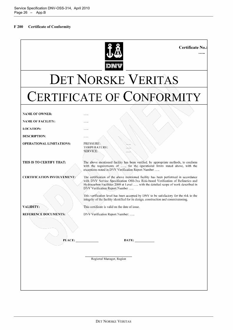
Service Specification DNV-OSS-314, April 2010 Page 26 – App.B
F 200 Certificate of Conformity
DET NORSKE VERITAS
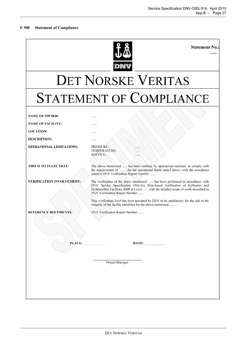
Service Specification DNV-OSS-314, April 2010 App.B – Page 27
F 300 Statement of Compliance
DET NORSKE VERITAS
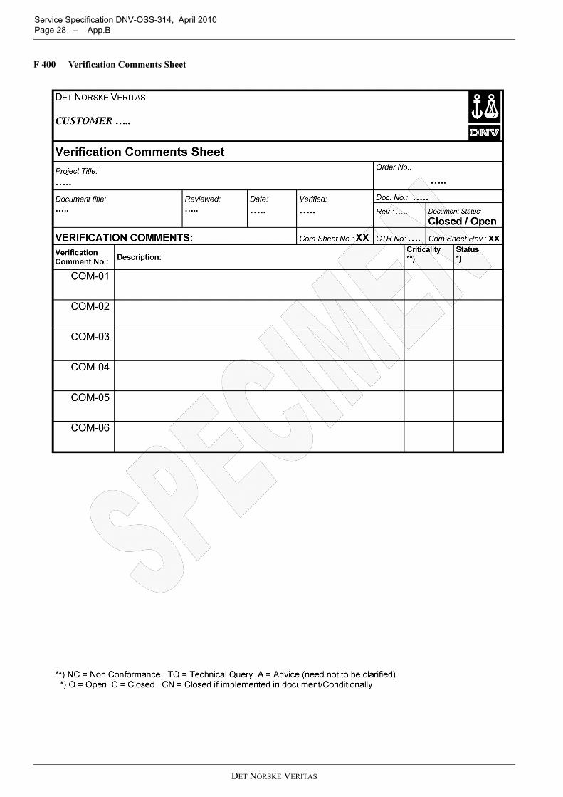
Service Specification DNV-OSS-314, April 2010 Page 28 – App.B
F 400 Verification Comments Sheet
DET NORSKE VERITAS
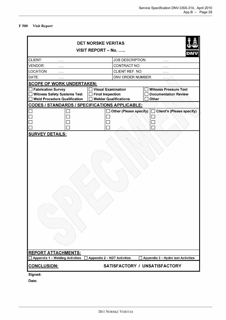
Service Specification DNV-OSS-314, April 2010 App.B – Page 29
F 500 Visit Report
DET NORSKE VERITAS
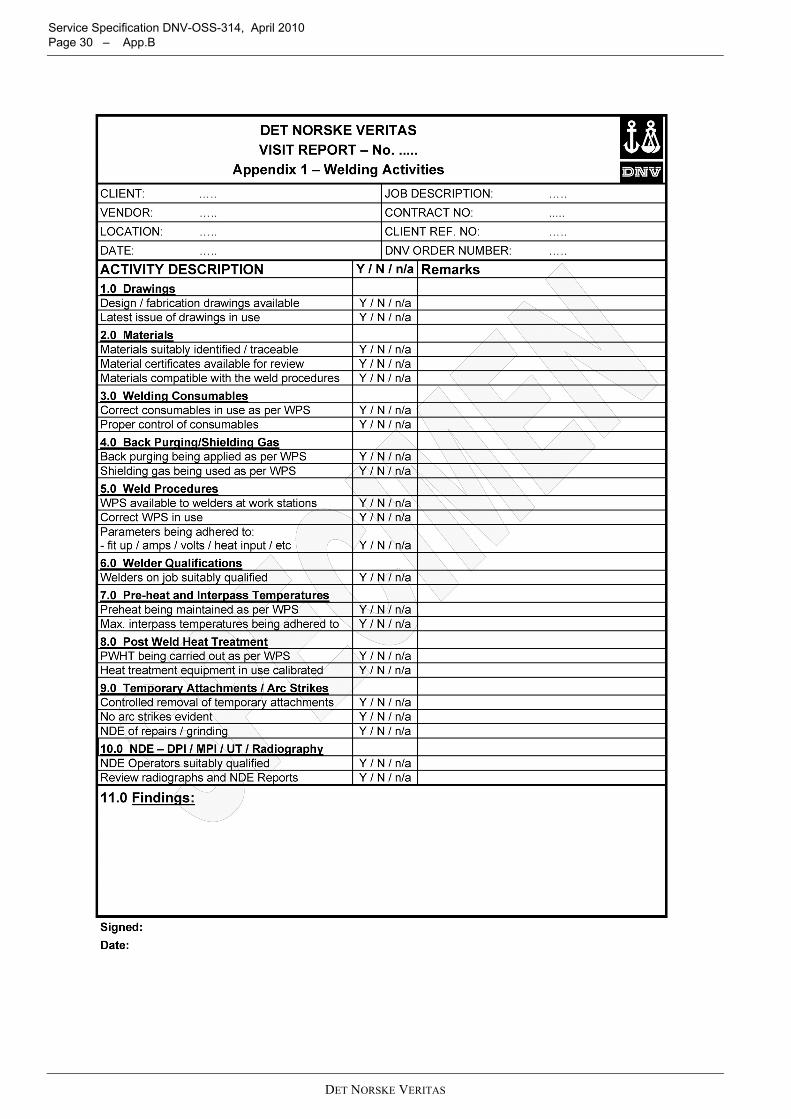
Service Specification DNV-OSS-314, April 2010 Page 30 – App.B
DET NORSKE VERITAS
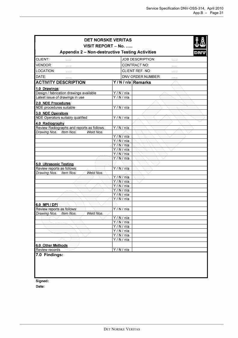
Service Specification DNV-OSS-314, April 2010 App.B – Page 31
DET NORSKE VERITAS
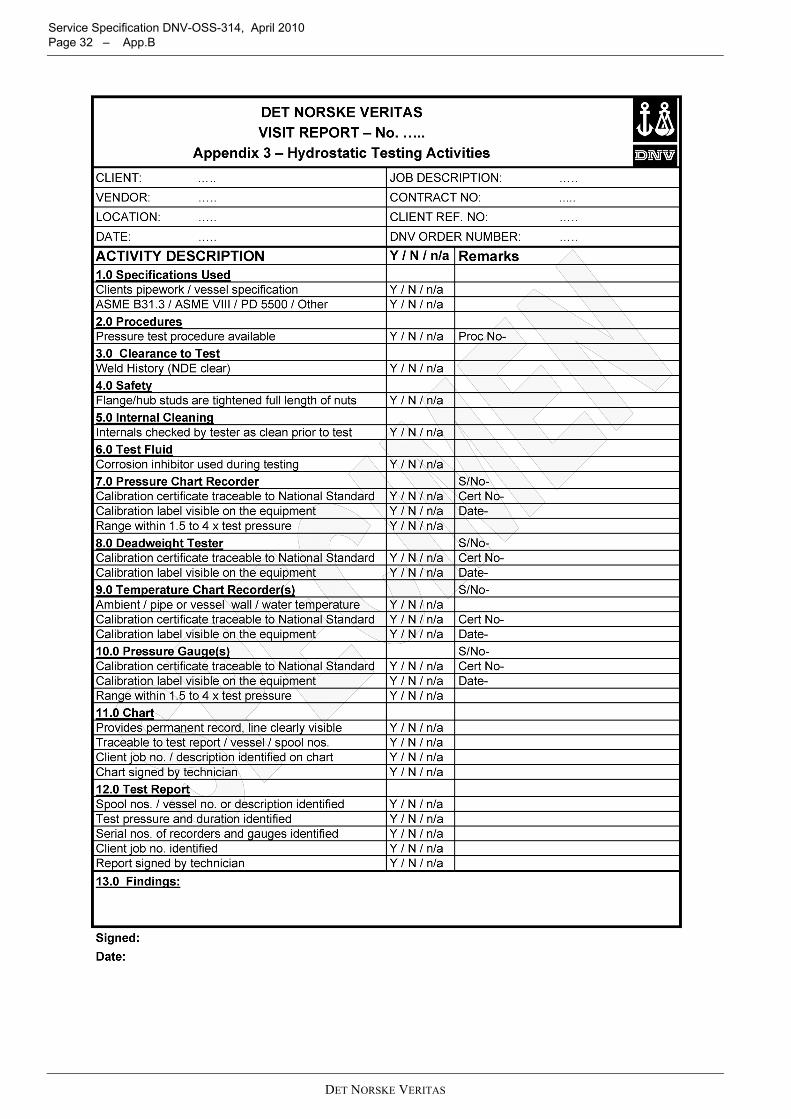
Service Specification DNV-OSS-314, April 2010 Page 32 – App.B
DET NORSKE VERITAS
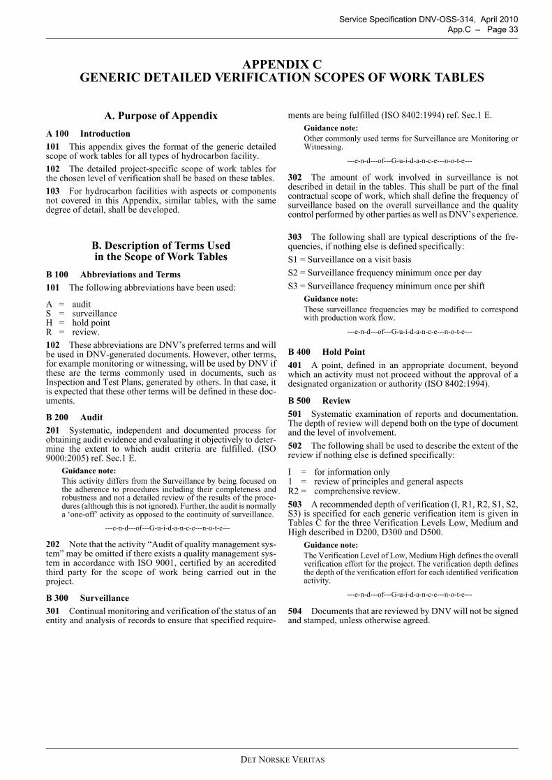
Service Specification DNV-OSS-314, April 2010 App.C – Page 33
APPENDIX C GENERIC DETAILED VERIFICATION SCOPES OF WORK TABLES
A. Purpose of AppendixA 100 Introduction101 This appendix gives the format of the generic detailedscope of work tables for all types of hydrocarbon facility. 102 The detailed project-specific scope of work tables forthe chosen level of verification shall be based on these tables.103 For hydrocarbon facilities with aspects or componentsnot covered in this Appendix, similar tables, with the samedegree of detail, shall be developed.
B. Description of Terms Used in the Scope of Work Tables
B 100 Abbreviations and Terms101 The following abbreviations have been used:
A = auditS = surveillanceH = hold pointR = review.102 These abbreviations are DNV’s preferred terms and willbe used in DNV-generated documents. However, other terms,for example monitoring or witnessing, will be used by DNV ifthese are the terms commonly used in documents, such asInspection and Test Plans, generated by others. In that case, itis expected that these other terms will be defined in these doc-uments.
B 200 Audit201 Systematic, independent and documented process forobtaining audit evidence and evaluating it objectively to deter-mine the extent to which audit criteria are fulfilled. (ISO9000:2005) ref. Sec.1 E.
Guidance note:This activity differs from the Surveillance by being focused onthe adherence to procedures including their completeness androbustness and not a detailed review of the results of the proce-dures (although this is not ignored). Further, the audit is normallya ‘one-off’ activity as opposed to the continuity of surveillance.
---e-n-d---of---G-u-i-d-a-n-c-e---n-o-t-e---
202 Note that the activity “Audit of quality management sys-tem” may be omitted if there exists a quality management sys-tem in accordance with ISO 9001, certified by an accreditedthird party for the scope of work being carried out in theproject.
B 300 Surveillance301 Continual monitoring and verification of the status of anentity and analysis of records to ensure that specified require-
ments are being fulfilled (ISO 8402:1994) ref. Sec.1 E.Guidance note:Other commonly used terms for Surveillance are Monitoring orWitnessing.
---e-n-d---of---G-u-i-d-a-n-c-e---n-o-t-e---
302 The amount of work involved in surveillance is notdescribed in detail in the tables. This shall be part of the finalcontractual scope of work, which shall define the frequency ofsurveillance based on the overall surveillance and the qualitycontrol performed by other parties as well as DNV’s experience.
303 The following shall are typical descriptions of the fre-quencies, if nothing else is defined specifically:S1 = Surveillance on a visit basisS2 = Surveillance frequency minimum once per dayS3 = Surveillance frequency minimum once per shift
Guidance note:These surveillance frequencies may be modified to correspondwith production work flow.
---e-n-d---of---G-u-i-d-a-n-c-e---n-o-t-e---
B 400 Hold Point401 A point, defined in an appropriate document, beyondwhich an activity must not proceed without the approval of adesignated organization or authority (ISO 8402:1994).
B 500 Review501 Systematic examination of reports and documentation.The depth of review will depend both on the type of documentand the level of involvement.502 The following shall be used to describe the extent of thereview if nothing else is defined specifically:
I = for information only1 = review of principles and general aspectsR2 = comprehensive review.503 A recommended depth of verification (I, R1, R2, S1, S2,S3) is specified for each generic verification item is given inTables C for the three Verification Levels Low, Medium andHigh described in D200, D300 and D500.
Guidance note:The Verification Level of Low, Medium High defines the overallverification effort for the project. The verification depth definesthe depth of the verification effort for each identified verificationactivity.
---e-n-d---of---G-u-i-d-a-n-c-e---n-o-t-e---
504 Documents that are reviewed by DNV will not be signedand stamped, unless otherwise agreed.
DET NORSKE VERITAS
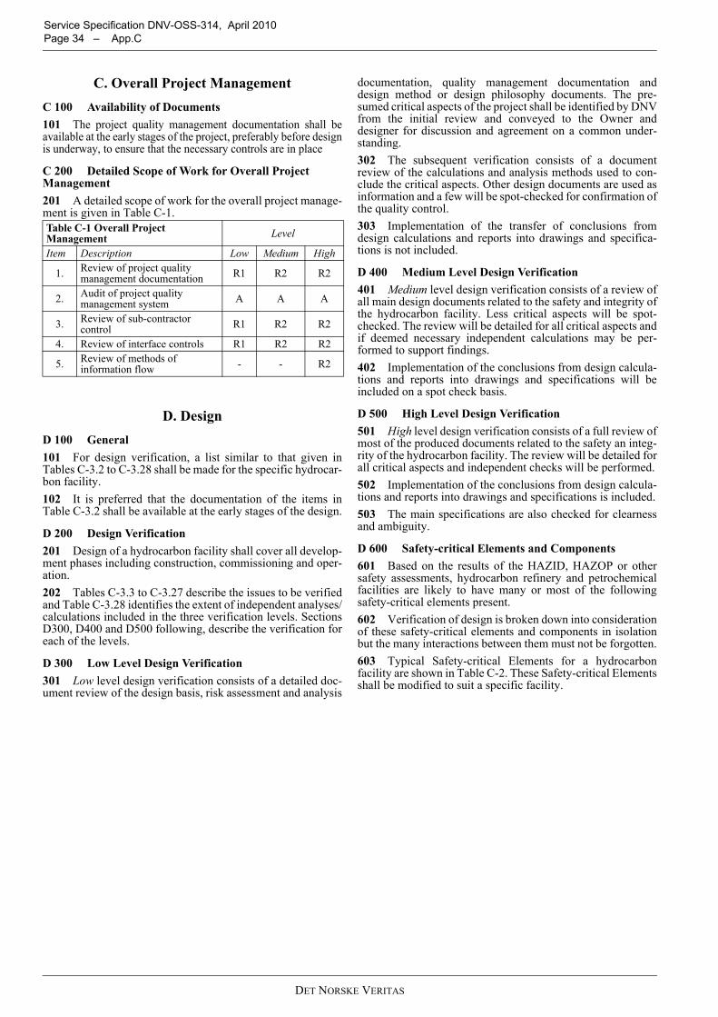
Service Specification DNV-OSS-314, April 2010 Page 34 – App.C
C. Overall Project ManagementC 100 Availability of Documents101 The project quality management documentation shall beavailable at the early stages of the project, preferably before designis underway, to ensure that the necessary controls are in place
C 200 Detailed Scope of Work for Overall Project Management201 A detailed scope of work for the overall project manage-ment is given in Table C-1.
D. DesignD 100 General101 For design verification, a list similar to that given inTables C-3.2 to C-3.28 shall be made for the specific hydrocar-bon facility.102 It is preferred that the documentation of the items inTable C-3.2 shall be available at the early stages of the design.
D 200 Design Verification201 Design of a hydrocarbon facility shall cover all develop-ment phases including construction, commissioning and oper-ation.202 Tables C-3.3 to C-3.27 describe the issues to be verifiedand Table C-3.28 identifies the extent of independent analyses/calculations included in the three verification levels. SectionsD300, D400 and D500 following, describe the verification foreach of the levels.
D 300 Low Level Design Verification301 Low level design verification consists of a detailed doc-ument review of the design basis, risk assessment and analysis
documentation, quality management documentation anddesign method or design philosophy documents. The pre-sumed critical aspects of the project shall be identified by DNVfrom the initial review and conveyed to the Owner anddesigner for discussion and agreement on a common under-standing.302 The subsequent verification consists of a documentreview of the calculations and analysis methods used to con-clude the critical aspects. Other design documents are used asinformation and a few will be spot-checked for confirmation ofthe quality control.303 Implementation of the transfer of conclusions fromdesign calculations and reports into drawings and specifica-tions is not included.
D 400 Medium Level Design Verification401 Medium level design verification consists of a review ofall main design documents related to the safety and integrity ofthe hydrocarbon facility. Less critical aspects will be spot-checked. The review will be detailed for all critical aspects andif deemed necessary independent calculations may be per-formed to support findings.402 Implementation of the conclusions from design calcula-tions and reports into drawings and specifications will beincluded on a spot check basis.
D 500 High Level Design Verification501 High level design verification consists of a full review ofmost of the produced documents related to the safety an integ-rity of the hydrocarbon facility. The review will be detailed forall critical aspects and independent checks will be performed.502 Implementation of the conclusions from design calcula-tions and reports into drawings and specifications is included.503 The main specifications are also checked for clearnessand ambiguity.
D 600 Safety-critical Elements and Components601 Based on the results of the HAZID, HAZOP or othersafety assessments, hydrocarbon refinery and petrochemicalfacilities are likely to have many or most of the followingsafety-critical elements present.602 Verification of design is broken down into considerationof these safety-critical elements and components in isolationbut the many interactions between them must not be forgotten.603 Typical Safety-critical Elements for a hydrocarbonfacility are shown in Table C-2. These Safety-critical Elementsshall be modified to suit a specific facility.
Table C-1 Overall Project Management Level
Item Description Low Medium High
1. Review of project quality management documentation R1 R2 R2
2. Audit of project quality management system A A A
3. Review of sub-contractor control R1 R2 R2
4. Review of interface controls R1 R2 R2
5. Review of methods of information flow - - R2
DET NORSKE VERITAS
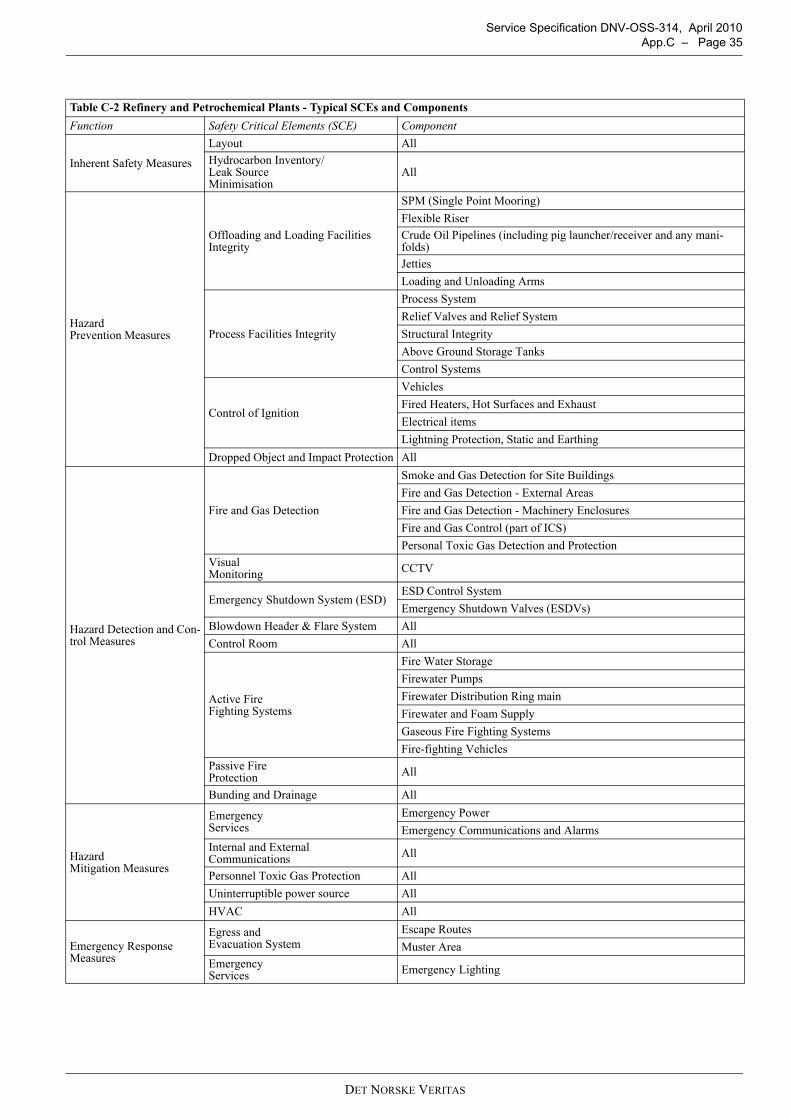
Service Specification DNV-OSS-314, April 2010 App.C – Page 35
Table C-2 Refinery and Petrochemical Plants - Typical SCEs and ComponentsFunction Safety Critical Elements (SCE) Component
Inherent Safety Measures
Layout AllHydrocarbon Inventory/Leak Source Minimisation
All
Hazard Prevention Measures
Offloading and Loading Facilities Integrity
SPM (Single Point Mooring)Flexible RiserCrude Oil Pipelines (including pig launcher/receiver and any mani-folds)JettiesLoading and Unloading Arms
Process Facilities Integrity
Process SystemRelief Valves and Relief SystemStructural IntegrityAbove Ground Storage TanksControl Systems
Control of Ignition
VehiclesFired Heaters, Hot Surfaces and ExhaustElectrical itemsLightning Protection, Static and Earthing
Dropped Object and Impact Protection All
Hazard Detection and Con-trol Measures
Fire and Gas Detection
Smoke and Gas Detection for Site BuildingsFire and Gas Detection - External AreasFire and Gas Detection - Machinery EnclosuresFire and Gas Control (part of ICS)Personal Toxic Gas Detection and Protection
Visual Monitoring CCTV
Emergency Shutdown System (ESD)ESD Control SystemEmergency Shutdown Valves (ESDVs)
Blowdown Header & Flare System AllControl Room All
Active Fire Fighting Systems
Fire Water StorageFirewater PumpsFirewater Distribution Ring mainFirewater and Foam SupplyGaseous Fire Fighting SystemsFire-fighting Vehicles
Passive Fire Protection All
Bunding and Drainage All
Hazard Mitigation Measures
Emergency Services
Emergency PowerEmergency Communications and Alarms
Internal and External Communications All
Personnel Toxic Gas Protection AllUninterruptible power source AllHVAC All
Emergency Response Measures
Egress and Evacuation System
Escape RoutesMuster Area
Emergency Services Emergency Lighting
DET NORSKE VERITAS
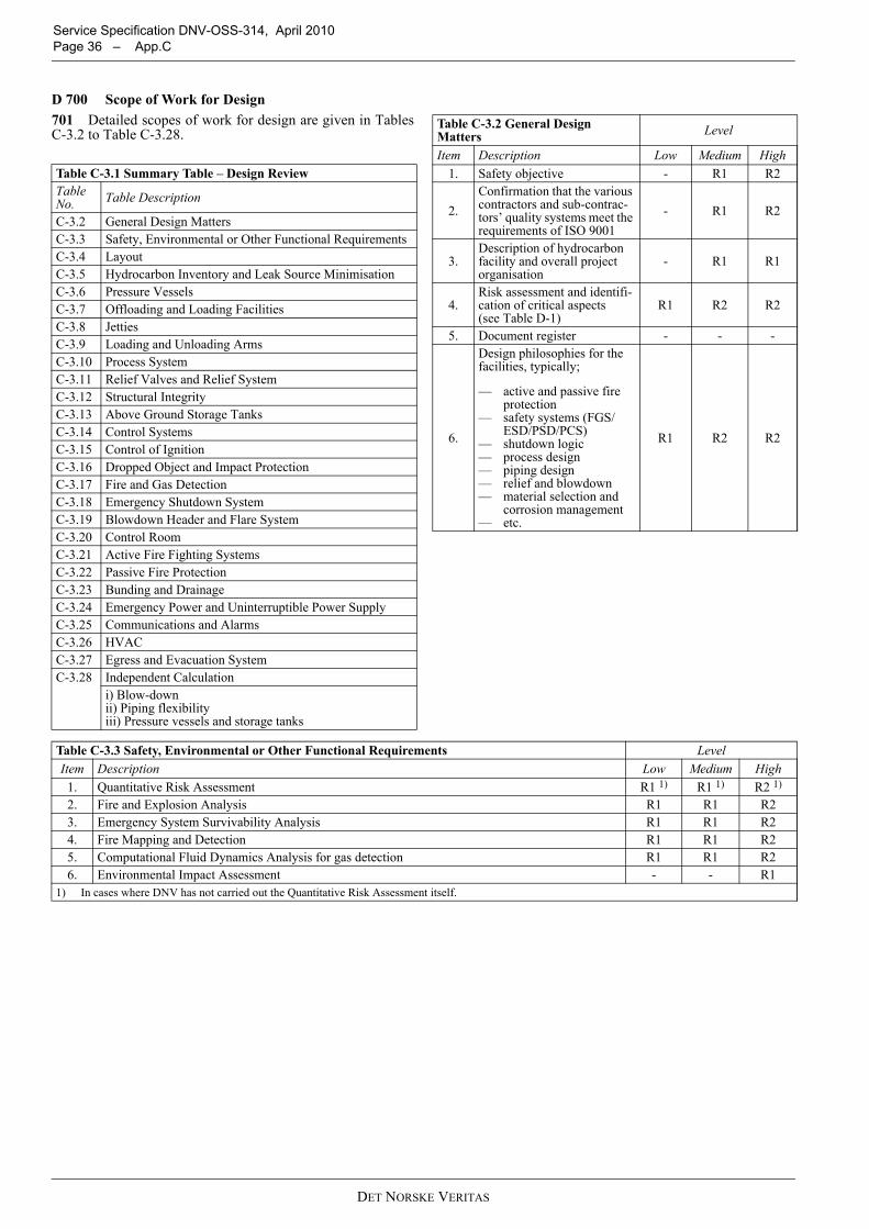
Service Specification DNV-OSS-314, April 2010 Page 36 – App.C
D 700 Scope of Work for Design701 Detailed scopes of work for design are given in TablesC-3.2 to Table C-3.28.
Table C-3.1 Summary Table – Design ReviewTable No. Table Description
C-3.2 General Design MattersC-3.3 Safety, Environmental or Other Functional RequirementsC-3.4 LayoutC-3.5 Hydrocarbon Inventory and Leak Source MinimisationC-3.6 Pressure VesselsC-3.7 Offloading and Loading FacilitiesC-3.8 JettiesC-3.9 Loading and Unloading ArmsC-3.10 Process SystemC-3.11 Relief Valves and Relief SystemC-3.12 Structural IntegrityC-3.13 Above Ground Storage TanksC-3.14 Control SystemsC-3.15 Control of IgnitionC-3.16 Dropped Object and Impact ProtectionC-3.17 Fire and Gas DetectionC-3.18 Emergency Shutdown SystemC-3.19 Blowdown Header and Flare SystemC-3.20 Control RoomC-3.21 Active Fire Fighting SystemsC-3.22 Passive Fire ProtectionC-3.23 Bunding and DrainageC-3.24 Emergency Power and Uninterruptible Power SupplyC-3.25 Communications and AlarmsC-3.26 HVACC-3.27 Egress and Evacuation SystemC-3.28 Independent Calculation
i) Blow-downii) Piping flexibilityiii) Pressure vessels and storage tanks
Table C-3.2 General Design Matters Level
Item Description Low Medium High1. Safety objective - R1 R2
2.Confirmation that the various contractors and sub-contrac-tors’ quality systems meet the requirements of ISO 9001
- R1 R2
3.Description of hydrocarbon facility and overall project organisation
- R1 R1
4.Risk assessment and identifi-cation of critical aspects (see Table D-1)
R1 R2 R2
5. Document register - - -
6.
Design philosophies for the facilities, typically;
— active and passive fire protection
— safety systems (FGS/ESD/PSD/PCS)
— shutdown logic— process design— piping design— relief and blowdown— material selection and
corrosion management— etc.
R1 R2 R2
Table C-3.3 Safety, Environmental or Other Functional Requirements LevelItem Description Low Medium High
1. Quantitative Risk Assessment R1 1) R1 1) R2 1)
2. Fire and Explosion Analysis R1 R1 R23. Emergency System Survivability Analysis R1 R1 R24. Fire Mapping and Detection R1 R1 R25. Computational Fluid Dynamics Analysis for gas detection R1 R1 R26. Environmental Impact Assessment - - R1
1) In cases where DNV has not carried out the Quantitative Risk Assessment itself.
DET NORSKE VERITAS
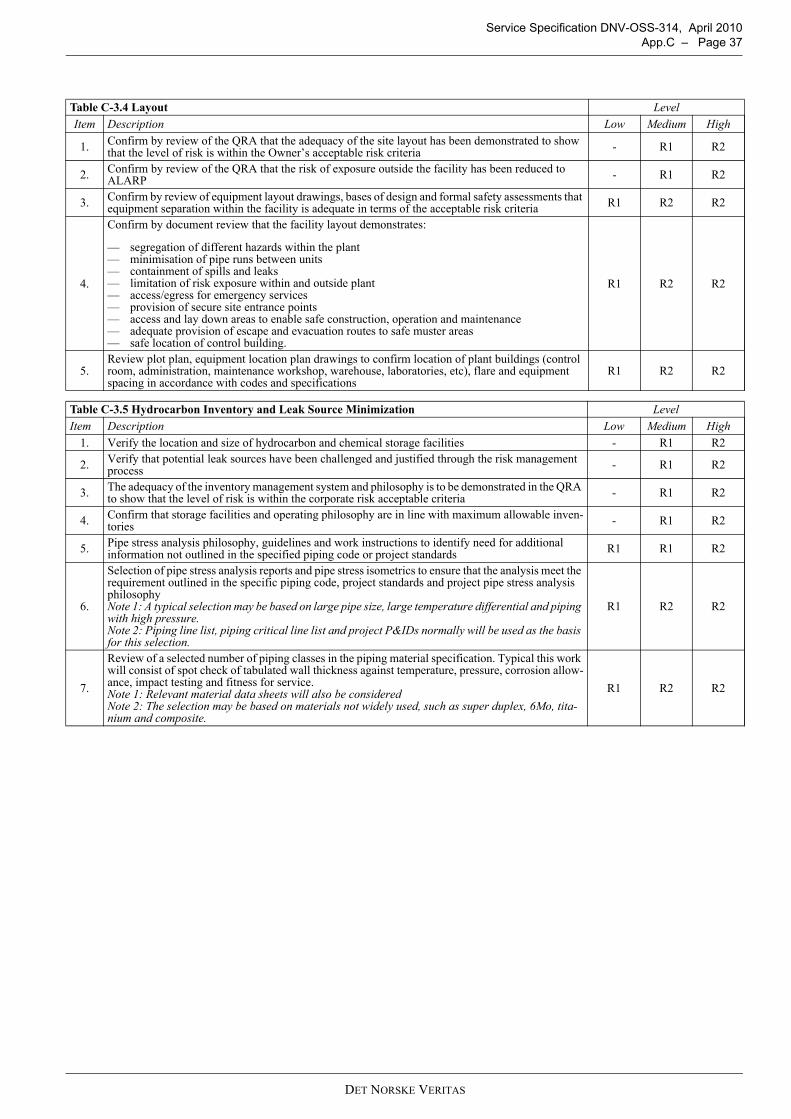
Service Specification DNV-OSS-314, April 2010 App.C – Page 37
Table C-3.4 Layout LevelItem Description Low Medium High
1. Confirm by review of the QRA that the adequacy of the site layout has been demonstrated to show that the level of risk is within the Owner’s acceptable risk criteria - R1 R2
2. Confirm by review of the QRA that the risk of exposure outside the facility has been reduced to ALARP - R1 R2
3. Confirm by review of equipment layout drawings, bases of design and formal safety assessments that equipment separation within the facility is adequate in terms of the acceptable risk criteria R1 R2 R2
4.
Confirm by document review that the facility layout demonstrates:
— segregation of different hazards within the plant— minimisation of pipe runs between units— containment of spills and leaks— limitation of risk exposure within and outside plant— access/egress for emergency services— provision of secure site entrance points— access and lay down areas to enable safe construction, operation and maintenance— adequate provision of escape and evacuation routes to safe muster areas— safe location of control building.
R1 R2 R2
5.Review plot plan, equipment location plan drawings to confirm location of plant buildings (control room, administration, maintenance workshop, warehouse, laboratories, etc), flare and equipment spacing in accordance with codes and specifications
R1 R2 R2
Table C-3.5 Hydrocarbon Inventory and Leak Source Minimization LevelItem Description Low Medium High
1. Verify the location and size of hydrocarbon and chemical storage facilities - R1 R2
2. Verify that potential leak sources have been challenged and justified through the risk management process - R1 R2
3. The adequacy of the inventory management system and philosophy is to be demonstrated in the QRA to show that the level of risk is within the corporate risk acceptable criteria - R1 R2
4. Confirm that storage facilities and operating philosophy are in line with maximum allowable inven-tories - R1 R2
5. Pipe stress analysis philosophy, guidelines and work instructions to identify need for additional information not outlined in the specified piping code or project standards R1 R1 R2
6.
Selection of pipe stress analysis reports and pipe stress isometrics to ensure that the analysis meet the requirement outlined in the specific piping code, project standards and project pipe stress analysis philosophyNote 1: A typical selection may be based on large pipe size, large temperature differential and piping with high pressure.Note 2: Piping line list, piping critical line list and project P&IDs normally will be used as the basis for this selection.
R1 R2 R2
7.
Review of a selected number of piping classes in the piping material specification. Typical this work will consist of spot check of tabulated wall thickness against temperature, pressure, corrosion allow-ance, impact testing and fitness for service.Note 1: Relevant material data sheets will also be consideredNote 2: The selection may be based on materials not widely used, such as super duplex, 6Mo, tita-nium and composite.
R1 R2 R2
DET NORSKE VERITAS
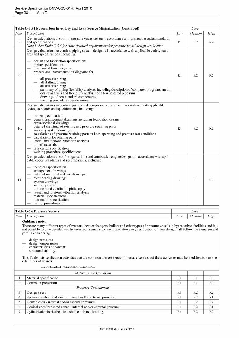
Service Specification DNV-OSS-314, April 2010 Page 38 – App.C
8.Design calculations to confirm pressure vessel design in accordance with applicable codes, standards and specifications.Note 1: See Table C-3.6 for more detailed requirements for pressure vessel design verification
R1 R2 R2
9.
Design calculations to confirm piping system design is in accordance with applicable codes, stand-ards and specifications, including:
— design and fabrication specifications— piping specifications— mechanical flow diagrams— process and instrumentation diagrams for:
— all process piping— all drilling piping— all utilities piping— summary of piping flexibility analyses including description of computer programs, meth-
ods of analysis and flexibility analysis of a few selected pipe runs— drawings of non-standard components— welding procedure specifications.
R1 R2 R2
10.
Design calculations to confirm pumps and compressors design is in accordance with applicable codes, standards and specifications, including:
— design specification— general arrangement drawings including foundation design— cross-sectional drawings— detailed drawings of rotating and pressure retaining parts— auxiliary system drawings— calculations of pressure retaining parts in both operating and pressure test conditions— calculations for rotating parts— lateral and torsional vibration analysis— bill of materials— fabrication specification— welding procedure specifications.
R1 R2 R2
11.
Design calculations to confirm gas turbine and combustion engine design is in accordance with appli-cable codes, standards and specifications, including:
— technical specification— arrangement drawings— detailed sectional and part drawings— rotor bearing drawings— system drawings— safety systems— turbine hood ventilation philosophy— lateral and torsional vibration analysis— material specifications— fabrication specification— testing procedures.
- R1 R2
Table C-3.6 Pressure Vessels LevelItem Description Low Medium High
Guidance note:There are many different types of reactors, heat exchangers, boilers and other types of pressure vessels in hydrocarbon facilities and it isnot possible to give detailed verification requirements for each one. However, verification of their design will follow the same generalpath in considering:
— design pressures— design temperatures— characteristics of contents— structural stability.
This Table lists verification activities that are common to most types of pressure vessels but these activities may be modified to suit spe-cific types of vessels.
---e-n-d---of---G-u-i-d-a-n-c-e---n-o-t-e---
Materials and Corrosion1. Material specification R1 R1 R22. Corrosion protection R1 R1 R2
Pressure Containment3. Design stress R1 R2 R24. Spherical/cylindrical shell - internal and/or external pressure R1 R2 R15. Domed ends - internal and/or external pressure R1 R2 R26. Conical ends/truncated cones - internal and/or external pressure R1 R2 R17. Cylindrical/spherical/conical shell combined loading R1 R2 R2
Table C-3.5 Hydrocarbon Inventory and Leak Source Minimization (Continued) LevelItem Description Low Medium High
DET NORSKE VERITAS
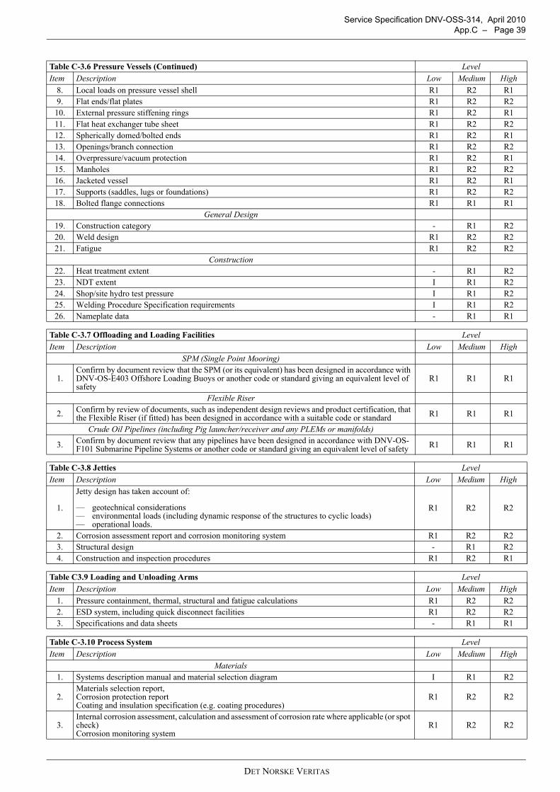
Service Specification DNV-OSS-314, April 2010 App.C – Page 39
8. Local loads on pressure vessel shell R1 R2 R19. Flat ends/flat plates R1 R2 R2
10. External pressure stiffening rings R1 R2 R111. Flat heat exchanger tube sheet R1 R2 R212. Spherically domed/bolted ends R1 R2 R113. Openings/branch connection R1 R2 R214. Overpressure/vacuum protection R1 R2 R115. Manholes R1 R2 R216. Jacketed vessel R1 R2 R117. Supports (saddles, lugs or foundations) R1 R2 R218. Bolted flange connections R1 R1 R1
General Design19. Construction category - R1 R220. Weld design R1 R2 R221. Fatigue R1 R2 R2
Construction22. Heat treatment extent - R1 R223. NDT extent I R1 R224. Shop/site hydro test pressure I R1 R225. Welding Procedure Specification requirements I R1 R226. Nameplate data - R1 R1
Table C-3.7 Offloading and Loading Facilities LevelItem Description Low Medium High
SPM (Single Point Mooring)
1.Confirm by document review that the SPM (or its equivalent) has been designed in accordance with DNV-OS-E403 Offshore Loading Buoys or another code or standard giving an equivalent level of safety
R1 R1 R1
Flexible Riser
2. Confirm by review of documents, such as independent design reviews and product certification, that the Flexible Riser (if fitted) has been designed in accordance with a suitable code or standard R1 R1 R1
Crude Oil Pipelines (including Pig launcher/receiver and any PLEMs or manifolds)
3. Confirm by document review that any pipelines have been designed in accordance with DNV-OS-F101 Submarine Pipeline Systems or another code or standard giving an equivalent level of safety R1 R1 R1
Table C-3.8 Jetties LevelItem Description Low Medium High
1.
Jetty design has taken account of:
— geotechnical considerations — environmental loads (including dynamic response of the structures to cyclic loads)— operational loads.
R1 R2 R2
2. Corrosion assessment report and corrosion monitoring system R1 R2 R23. Structural design - R1 R24. Construction and inspection procedures R1 R2 R1
Table C3.9 Loading and Unloading Arms LevelItem Description Low Medium High
1. Pressure containment, thermal, structural and fatigue calculations R1 R2 R22. ESD system, including quick disconnect facilities R1 R2 R23. Specifications and data sheets - R1 R1
Table C-3.10 Process System LevelItem Description Low Medium High
Materials1. Systems description manual and material selection diagram I R1 R2
2.Materials selection report, Corrosion protection reportCoating and insulation specification (e.g. coating procedures)
R1 R2 R2
3.Internal corrosion assessment, calculation and assessment of corrosion rate where applicable (or spot check)Corrosion monitoring system
R1 R2 R2
Table C-3.6 Pressure Vessels (Continued) LevelItem Description Low Medium High
DET NORSKE VERITAS
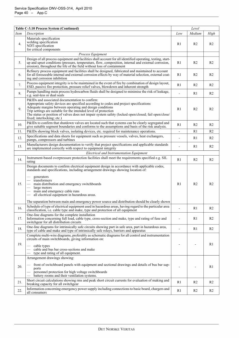
Service Specification DNV-OSS-314, April 2010 Page 40 – App.C
4.Materials specification welding specificationNDT-specificationfor critical components
R1 R2 R2
Process Equipment
5.Design of all process equipment and facilities shall account for all identified operating, testing, start-up and upset conditions (pressure, temperature, flow, composition, internal and external corrosion, erosion), throughout the life of the field without loss of containment
R1 R2 R2
6.Refinery process equipment and facilities shall be designed, fabricated and maintained to account for all foreseeable internal and external corrosion effects by way of material selection, external coat-ing and corrosion inhibition
R1 R2 R2
7. Process equipment integrity is to be maintained in the event of fire by combination of design layout, ESD, passive fire protection, pressure relief valves, blowdown and inherent strength R1 R2 R2
8. Pumps handling main process hydrocarbon fluids shall be designed to minimise the risk of leakage, e.g. seal-less or dual seals - R1 R2
9.
P&IDs and associated documentation to confirm: Appropriate safety devices are specified according to codes and project specificationsAdequate margins between operating and design conditions Trip settings are suitable for the intended level of protectionThe status or position of valves does not impair system safety (locked open/closed; fail open/close/fixed; interlocking; etc.)
R1 R2 R2
10. P&IDs to confirm that shutdown valves are located such that systems can be clearly segregated and give suitable segment boundaries and conforms to the assumptions and basis of the risk analysis. R1 R2 R2
11. P&IDs showing block valves, isolating devices, etc. required for maintenance operations. - R1 R2
12. Specifications and data sheets for equipment such as pressure vessels, valves, heat exchangers, pumps, compressors and turbines - R1 R2
13. Manufacturers design documentation to verify that project specifications and applicable standards are implemented correctly with respect to equipment integrity - R1 R2
Electrical and Instrumentation Equipment
14. Instrument-based overpressure protection facilities shall meet the requirements specified e.g. SIL rating R1 R2 R2
15.
Design documents to confirm electrical equipment design in accordance with applicable codes, standards and specifications, including arrangement drawings showing location of:
— generators— transformers— main distribution and emergency switchboards— large motors— main and emergency cable runs— all electrical equipment in hazardous areas.
The separation between main and emergency power source and distribution should be clearly shown
R1 R2 R2
16. Schedule of type of electrical equipment used in hazardous areas, having regard to the particular area classification, i.e. cable type and make, type and protection of all equipment - R1 R2
17.One-line diagrams for the complete installationInformation concerning full load, cable type, cross-section and make, type and rating of fuse and switchgear for all distribution circuits
- R1 R2
18. One-line diagrams for intrinsically safe circuits showing part in safe area, part in hazardous area, type of cable and make and type of intrinsically safe relays, barriers and apparatus - R1 R2
19.
Complete multi-wire diagrams, preferably as schematic diagrams for all control and instrumentation circuits of main switchboards, giving information on:
— cable types— cable and bus bar cross-sections and make— type and rating of all equipment.
- - R1
20.
Arrangement drawings showing:
— front of switchboard panels with equipment and sectional drawings and details of bus bar sup-ports
— personnel protection for high voltage switchboards — battery rooms and their ventilation systems.
- - R1
21. Short circuit calculations showing rms and peak short circuit currents for evaluation of making and breaking capacity for all switchgear R1 R2 R2
22. Information concerning emergency power supply including connections to basic board, chargers and all consumers R1 R2 R2
Table C-3.10 Process System (Continued) LevelItem Description Low Medium High
DET NORSKE VERITAS
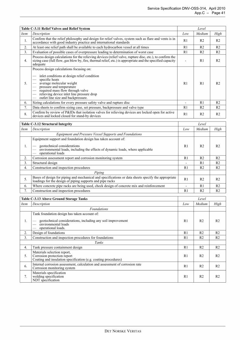
Service Specification DNV-OSS-314, April 2010 App.C – Page 41
Table C-3.11 Relief Valves and Relief System LevelItem Description Low Medium High
1. Confirm that the relief philosophy and design for relief valves, system such as flare and vents is in accordance with good industry practice and international standards R1 R2 R2
2. At least one relief path shall be available to each hydrocarbon vessel at all times R1 R2 R23. Evaluation of possible cases of overpressure leading to determination of worst case R1 R2 R2
4.Process design calculations for the relieving devices (relief valve, rupture disc, etc.), to confirm the sizing case (full flow, gas blow by, fire, thermal relief, etc.) is appropriate and the specified capacity adequate
- R1 R2
5.
Process design calculations focusing on:
— inlet conditions at design relief condition— specific heats— average molecular weight— pressure and temperature— required mass flow through valve— relieving device inlet line pressure drop— outlet line size and backpressure.
R1 R1 R2
6. Sizing calculations for every pressure safety valve and rupture disc - R1 R27. Data sheets to confirm sizing case, set pressure, backpressure and valve type R1 R2 R2
8. Confirm by review of P&IDs that isolation valves for relieving devices are locked open for active devices and locked closed for stand-by devices R1 R2 R2
Table C-3.12 Structural Integrity LevelItem Description Low Medium High
Equipment and Pressure Vessel Supports and Foundations
1.
Equipment support and foundation design has taken account of:
— geotechnical considerations— environmental loads, including the effects of dynamic loads, where applicable— operational loads
R1 R2 R2
2. Corrosion assessment report and corrosion monitoring system R1 R2 R23. Structural design - R1 R24. Construction and inspection procedures R1 R2 R2
Piping
5. Bases of design for piping and mechanical and specifications or data sheets specify the appropriate loadings for the design of piping supports and pipe racks R1 R2 R2
6. Where concrete pipe racks are being used, check design of concrete mix and reinforcement - R1 R27. Construction and inspection procedures R1 R2 R2
Table C-3.13 Above Ground Storage Tanks LevelItem Description Low Medium High
Foundations
1.
Tank foundation design has taken account of:
— geotechnical considerations, including any soil improvement— environmental loads— operational loads.
R1 R2 R2
2. Design of foundations R1 R2 R23. Construction and inspection procedures for foundations R1 R2 R2
Tanks4. Tank pressure containment design R1 R2 R2
5.Materials selection report, Corrosion protection reportCoating and insulation specification (e.g. coating procedures)
R1 R2 R2
6. Internal corrosion assessment, calculation and assessment of corrosion rateCorrosion monitoring system R1 R2 R2
7.Materials specification welding specificationNDT specification
R1 R2 R2
DET NORSKE VERITAS
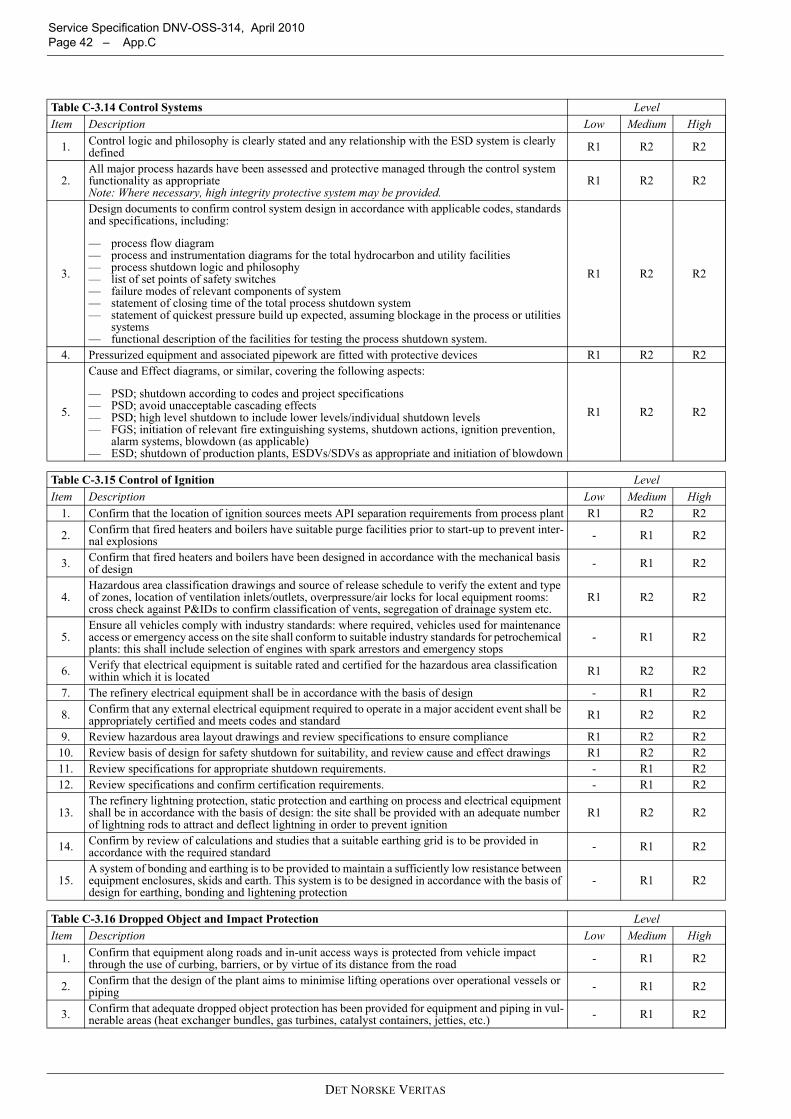
Service Specification DNV-OSS-314, April 2010 Page 42 – App.C
Table C-3.14 Control Systems LevelItem Description Low Medium High
1. Control logic and philosophy is clearly stated and any relationship with the ESD system is clearly defined R1 R2 R2
2.All major process hazards have been assessed and protective managed through the control system functionality as appropriateNote: Where necessary, high integrity protective system may be provided.
R1 R2 R2
3.
Design documents to confirm control system design in accordance with applicable codes, standards and specifications, including:
— process flow diagram— process and instrumentation diagrams for the total hydrocarbon and utility facilities— process shutdown logic and philosophy— list of set points of safety switches— failure modes of relevant components of system— statement of closing time of the total process shutdown system— statement of quickest pressure build up expected, assuming blockage in the process or utilities
systems— functional description of the facilities for testing the process shutdown system.
R1 R2 R2
4. Pressurized equipment and associated pipework are fitted with protective devices R1 R2 R2
5.
Cause and Effect diagrams, or similar, covering the following aspects:
— PSD; shutdown according to codes and project specifications— PSD; avoid unacceptable cascading effects— PSD; high level shutdown to include lower levels/individual shutdown levels— FGS; initiation of relevant fire extinguishing systems, shutdown actions, ignition prevention,
alarm systems, blowdown (as applicable)— ESD; shutdown of production plants, ESDVs/SDVs as appropriate and initiation of blowdown
R1 R2 R2
Table C-3.15 Control of Ignition LevelItem Description Low Medium High
1. Confirm that the location of ignition sources meets API separation requirements from process plant R1 R2 R2
2. Confirm that fired heaters and boilers have suitable purge facilities prior to start-up to prevent inter-nal explosions - R1 R2
3. Confirm that fired heaters and boilers have been designed in accordance with the mechanical basis of design - R1 R2
4.Hazardous area classification drawings and source of release schedule to verify the extent and type of zones, location of ventilation inlets/outlets, overpressure/air locks for local equipment rooms: cross check against P&IDs to confirm classification of vents, segregation of drainage system etc.
R1 R2 R2
5.Ensure all vehicles comply with industry standards: where required, vehicles used for maintenance access or emergency access on the site shall conform to suitable industry standards for petrochemical plants: this shall include selection of engines with spark arrestors and emergency stops
- R1 R2
6. Verify that electrical equipment is suitable rated and certified for the hazardous area classification within which it is located R1 R2 R2
7. The refinery electrical equipment shall be in accordance with the basis of design - R1 R2
8. Confirm that any external electrical equipment required to operate in a major accident event shall be appropriately certified and meets codes and standard R1 R2 R2
9. Review hazardous area layout drawings and review specifications to ensure compliance R1 R2 R210. Review basis of design for safety shutdown for suitability, and review cause and effect drawings R1 R2 R211. Review specifications for appropriate shutdown requirements. - R1 R212. Review specifications and confirm certification requirements. - R1 R2
13.The refinery lightning protection, static protection and earthing on process and electrical equipment shall be in accordance with the basis of design: the site shall be provided with an adequate number of lightning rods to attract and deflect lightning in order to prevent ignition
R1 R2 R2
14. Confirm by review of calculations and studies that a suitable earthing grid is to be provided in accordance with the required standard - R1 R2
15.A system of bonding and earthing is to be provided to maintain a sufficiently low resistance between equipment enclosures, skids and earth. This system is to be designed in accordance with the basis of design for earthing, bonding and lightening protection
- R1 R2
Table C-3.16 Dropped Object and Impact Protection LevelItem Description Low Medium High
1. Confirm that equipment along roads and in-unit access ways is protected from vehicle impact through the use of curbing, barriers, or by virtue of its distance from the road - R1 R2
2. Confirm that the design of the plant aims to minimise lifting operations over operational vessels or piping - R1 R2
3. Confirm that adequate dropped object protection has been provided for equipment and piping in vul-nerable areas (heat exchanger bundles, gas turbines, catalyst containers, jetties, etc.) - R1 R2
DET NORSKE VERITAS
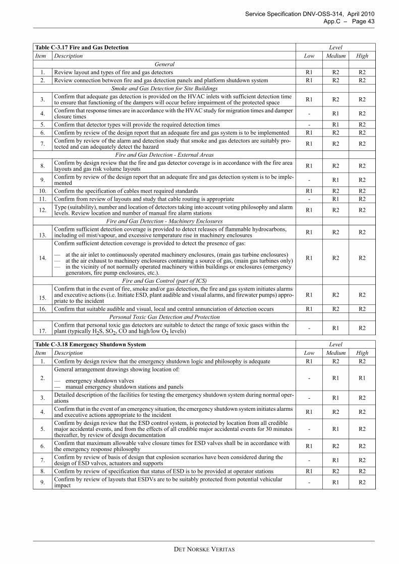
Service Specification DNV-OSS-314, April 2010 App.C – Page 43
Table C-3.17 Fire and Gas Detection LevelItem Description Low Medium High
General1. Review layout and types of fire and gas detectors R1 R2 R22. Review connection between fire and gas detection panels and platform shutdown system R1 R2 R2
Smoke and Gas Detection for Site Buildings
3. Confirm that adequate gas detection is provided on the HVAC inlets with sufficient detection time to ensure that functioning of the dampers will occur before impairment of the protected space R1 R2 R2
4. Confirm that response times are in accordance with the HVAC study for migration times and damper closure times - R1 R2
5. Confirm that detector types will provide the required detection times - R1 R26. Confirm by review of the design report that an adequate fire and gas system is to be implemented R1 R2 R2
7. Confirm by review of the alarm and detection study that smoke and gas detectors are suitably pro-tected and can adequately detect the hazard R1 R2 R2
Fire and Gas Detection - External Areas
8. Confirm by design review that the fire and gas detector coverage is in accordance with the fire area layouts and gas risk volume layouts R1 R2 R2
9. Confirm by review of the design report that an adequate fire and gas detection system is to be imple-mented - R1 R2
10. Confirm the specification of cables meet required standards R1 R2 R211. Confirm from review of layouts and study that cable routing is appropriate - R1 R2
12. Type (suitability), number and location of detectors taking into account voting philosophy and alarm levels. Review location and number of manual fire alarm stations R1 R2 R2
Fire and Gas Detection - Machinery Enclosures
13.Confirm sufficient detection coverage is provided to detect releases of flammable hydrocarbons, including oil mist/vapour, and excessive temperature rise in machinery enclosures R1 R2 R2
14.
Confirm sufficient detection coverage is provided to detect the presence of gas:
— at the air inlet to continuously operated machinery enclosures, (main gas turbine enclosures)— at the air exhaust to machinery enclosures containing a source of gas, (main gas turbines only)— in the vicinity of not normally operated machinery within buildings or enclosures (emergency
generators, fire pump enclosures, etc.).
R1 R2 R2
Fire and Gas Control (part of ICS)
15.Confirm that in the event of fire, smoke and/or gas detection, the fire and gas system initiates alarms and executive actions (i.e. Initiate ESD, plant audible and visual alarms, and firewater pumps) appro-priate to the incident
R1 R2 R2
16. Confirm that suitable audible and visual, local and central annunciation of detection occurs R1 R2 R2Personal Toxic Gas Detection and Protection
17.Confirm that personal toxic gas detectors are suitable to detect the range of toxic gases within the plant (typically H2S, SO2, CO and high/low O2 levels) - R1 R2
Table C-3.18 Emergency Shutdown System LevelItem Description Low Medium High
1. Confirm by design review that the emergency shutdown logic and philosophy is adequate R1 R2 R2
2.General arrangement drawings showing location of:
— emergency shutdown valves— manual emergency shutdown stations and panels
- R1 R1
3. Detailed description of the facilities for testing the emergency shutdown system during normal oper-ations - R1 R2
4. Confirm that in the event of an emergency situation, the emergency shutdown system initiates alarms and executive actions appropriate to the incident R1 R2 R2
5.Confirm by design review that the ESD control system, is protected by location from all credible major accidental events, and from the effects of all credible major accidental events for 30 minutes thereafter, by review of design documentation
- R1 R2
6. Confirm that maximum allowable valve closure times for ESD valves shall be in accordance with the emergency response philosophy R1 R2 R2
7. Confirm by review of basis of design that explosion scenarios have been considered during the design of ESD valves, actuators and supports - R1 R2
8. Confirm by review of specification that status of ESD is to be provided at operator stations R1 R2 R2
9. Confirm by review of layouts that ESDVs are to be suitably protected from potential vehicular impact - R1 R2
DET NORSKE VERITAS
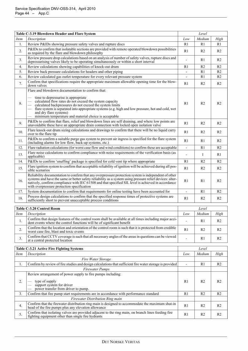
Service Specification DNV-OSS-314, April 2010 Page 44 – App.C
Table C-3.19 Blowdown Header and Flare System LevelItem Description Low Medium High
1. Review P&IDs showing pressure safety valves and rupture discs R1 R1 R1
2. P&IDs to confirm that isolatable sections are provided with remote operated blowdown possibilities as required by the flare and blowdown philosophy R1 R2 R2
3. Review pressure drop calculations based on an analysis of number of safety valves, rupture discs and depressurising valves likely to be operating simultaneously or within a short interval - R1 R2
4. Review calculations showing capabilities of knock-out drum R1 R2 R25. Review back pressure calculations for headers and other piping - R1 R26. Review calculated gas outlet temperature for every relevant pressure system - R1 R2
7. Confirm that specifications require the appropriate maximum allowable opening time for the blow-down valves R1 R2 R2
8.
Flare and blowdown documentation to confirm that:
— time to depressurise is appropriate— calculated flow rates do not exceed the system capacity— calculated backpressures do not exceed the system limits— flare system is separated into appropriate systems (e.g. high and low pressure, hot and cold, wet
and dry flare systems)— minimum temperature and material choice is acceptable
R1 R2 R2
9. P&IDs to confirm that flare, relief and blowdown lines are self draining, and where low points are unavoidable these have an appropriate drain connection with locked open isolation valve R1 R2 R2
10. Flare knock-out drum sizing calculations and drawings to confirm that there will be no liquid carry over to the flare tip R1 R2 R2
11. P&IDs to confirm a suitable purge gas system to prevent air ingress is specified for the flare system (including alarms for low flow, back-up systems, etc.) R1 R1 R2
12. Flare radiation calculations (for worst case flow and wind conditions) to confirm these are acceptable - R1 R2
13. Flare noise calculations to confirm compliance with noise requirements of the verification basis (as applicable) - I R1
14. P&IDs to confirm ‘snuffing’ package is specified for cold vent tip where appropriate R1 R2 R2
15. Flare ignition system to confirm that acceptable reliability of ignition will be achieved during all pos-sible scenarios R1 R2 R2
16.Reliability documentation to confirm that any overpressure protection system is independent of other systems and have the same or better safety reliability as a system using pressure relief devices: alter-natively, confirm compliance with IEC 61508 and that specified SIL level is achieved in accordance with overpressure protection specification
R1 R1 R2
17. System documentation to confirm that requirements for online testing have been accounted for - R1 R2
18. Process design calculations to confirm that the specified response times of protective systems are sufficiently short to prevent unacceptable process conditions R1 R2 R2
Table C-3.20 Control Room LevelItem Description Low Medium High
1. Confirm that design features of the control room shall be available at all times including major acci-dent events where the control functions will be of significant benefit - R1 R2
2. Confirm that the location and orientation of the control room is such that it is protected from credible worst case fire, blast and toxic events R1 R2 R2
3. Confirm that CCTV coverage is such that all necessary angles of the areas in questions can be viewed at a central protected location - R1 R2
Table C-3.21 Active Fire Fighting Systems LevelItem Description Low Medium High
Fire Water Storage1. Confirm by review of fire studies and design calculations that sufficient fire water storage is provided - R1 R2
Firewater Pumps
2.
Review arrangement of power supply to fire pumps including:
— type of supply— support system for driver— power transfer from driver to pump.
R1 R2 R2
3. Confirm that fire pump start requirements are in accordance with performance standard R1 R2 R2Firewater Distribution Ring main
4. Confirm that the firewater distribution ring main is designed to accommodate the maximum shut-in head of the fire pumps plus any elevation allowance R1 R2 R2
5. Confirm that isolating valves are provided adjacent to the ring main, on branch lines feeding fire fighting equipment other than single fire hydrants R1 R2 R2
DET NORSKE VERITAS
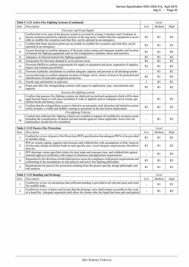
Service Specification DNV-OSS-314, April 2010 App.C – Page 45
Firewater and Foam Supply
6.Confirm that every area of the process system is covered by at least 2 monitors and 2 hydrants in diverse locations and fed by separate sections of the ring main. Confirm that this equipment is acces-sible in credible fire scenarios such that they can be operated in an emergency
R1 R1 R2
7. Confirm that foam injection points are accessible in credible fire scenarios such that they can be operated in an emergency R1 R1 R2
8. Layout drawings to confirm adequacy of firewater main routing and adequate number and location of manual fire fighting equipment such as fire extinguishers, hydrants, hoses and monitors R1 R1 R2
9. Adequacy of selected manual fire fighting equipment R1 R1 R210. Sizing basis for firewater demand to cover process areas R1 R1 R2
11. Firewater P&IDs to confirm requirements for supply to equipment and areas, separation of supplies, bypass and isolation possibilities R1 R1 R2
12. Firewater hydraulic calculations to confirm adequate capacity and pressure to all discharge points - R1 R2
13. Layout drawings to confirm adequate location of deluge valves, choice of areas to be protected and identification of dedicated equipment protection. R1 R1 R2
14. Nozzle type and density in each area I R1 R1
15. Foam and other fire extinguishing systems with respect to application, type, concentration and capacity R1 R1 R2
Gaseous fire-fighting systems
16.Confirm that gaseous fire-fighting systems are deployed on enclosed equipment which will be dam-aged beyond repair or will cause escalation if water is applied such as computer server rooms, gas turbine hoods and battery rooms
- R1 R2
17. Confirm that the extinguishing system is linked to an automatic early detection and initiation system which includes a visible and audible warning to personnel in the area before deployment R1 R1 R2
Fire-fighting Vehicles
18.Confirm that sufficient fire-fighting vehicles are available to support all credible fire scenarios onsite including the consideration of mutual aid and outside agencies where applicable: down time for maintenance should also be considered
- R1 R2
Table C-3.22 Passive Fire Protection LevelItem Description Low Medium High
1. Confirm by review of passive Fire Protection (PFP) specification that adequate PFP is to be provided of suitable rating R1 R1 R2
2.PFP on vessels, piping, supports and structure and withhold this with assumptions in Risk Analysis (if relevant), design accidental loads in each specific area, vessel integrity requirements, blowdown time etc.
R1 R1 R2
3. PFP drawings versus specified criteria for heat loads and exposure time, and withhold this against material approval certificates with respect to thickness and application requirements - R1 R2
4. Separation by fire divisions of individual process areas for compliance with project requirements and conforming to the assumptions in risk analysis and active fire fighting philosophy R1 R1 R2
5. Requirements for passive fire protection resulting from the project specific design philosophy and risk analysis R1 R1 R2
Table C-3.23 Bunding and Drainage LevelItem Description Low Medium High
1. Confirm by review of calculations that sufficient bunding is provided at all relevant areas and sized for credible leaks. - R1 R2
2. Confirm by review of plans and layouts that the drainage valve shall remain accessible in the event of a bund fire. Adequate separation shall allow for closure after the liquid has been spilt and ignited - R1 R2
Table C-3.21 Active Fire Fighting Systems (Continued) LevelItem Description Low Medium High
DET NORSKE VERITAS
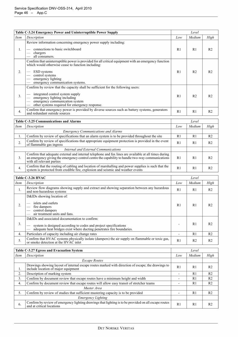
Service Specification DNV-OSS-314, April 2010 Page 46 – App.C
Table C-3.24 Emergency Power and Uninterruptible Power Supply LevelItem Description Low Medium High
1.
Review information concerning emergency power supply including:
— connections to basic switchboard— chargers— all consumers.
R1 R1 R2
2.
Confirm that uninterruptible power is provided for all critical equipment with an emergency function which would otherwise cease to function including:
— ESD systems— control systems— emergency lighting— emergency communication systems.
R1 R2 R2
3.
Confirm by review that the capacity shall be sufficient for the following users:
— integrated control system supply— emergency lighting including— emergency communication system— other systems required for emergency response.
R1 R2 R2
4. Confirm that emergency power is provided by diverse sources such as battery systems, generators and redundant outside sources R1 R1 R2
Table C-3.25 Communications and Alarms LevelItem Description Low Medium High
Emergency Communications and Alarms1. Confirm by review of specifications that an alarm system is to be provided throughout the site R1 R1 R2
2. Confirm by review of specifications that appropriate equipment protection is provided in the event of flammable gas ingress R1 R1 R2
Internal and External Communications
3.Confirm that adequate external and internal telephone and fax lines are available at all times during an emergency giving the emergency control centre the capability to handle two-way communications with all relevant parties
R1 R1 R2
4. Confirm that the routing of cabling and location of marshalling and power supplies is such that the system is protected from credible fire, explosion and seismic and weather events R1 R1 R2
Table C-3.26 HVAC LevelItem Description Low Medium High
1. Review flow diagrams showing supply and extract and showing separation between any hazardous and non-hazardous systems R1 R1 R2
2.
D&IDs showing location of:
— inlets and outlets— fire dampers— control dampers— air treatment units and fans.
R1 R1 R2
3.D&IDs and associated documentation to confirm:
— system is designed according to codes and project specifications— adequate heat bridges exist where ducting penetrates fire boundaries.
- R1 R2
4. Particulars of capacity including air change rates - R1 R2
5. Confirm that HVAC systems physically isolate (dampers) the air supply on flammable or toxic gas, or smoke detection at the HVAC inlet R1 R2 R2
Table C-3.27 Egress and Evacuation System LevelItem Description Low Medium High
Escape Routes
1.Drawings showing layout of internal escape routes marked with direction of escape; the drawings to include location of major equipment R1 R1 R2
2. Description of marking system - R1 R23. Confirm by document review that escape routes have a minimum height and width - R1 R24. Confirm by document review that escape routes will allow easy transit of stretcher teams - R1 R2
Muster Area5. Confirm by review of studies that sufficient mustering capacity is to be provided - R1 R2
Emergency Lighting
6. Confirm by review of emergency lighting drawings that lighting is to be provided on all escape routes and at critical locations R1 R1 R2
DET NORSKE VERITAS
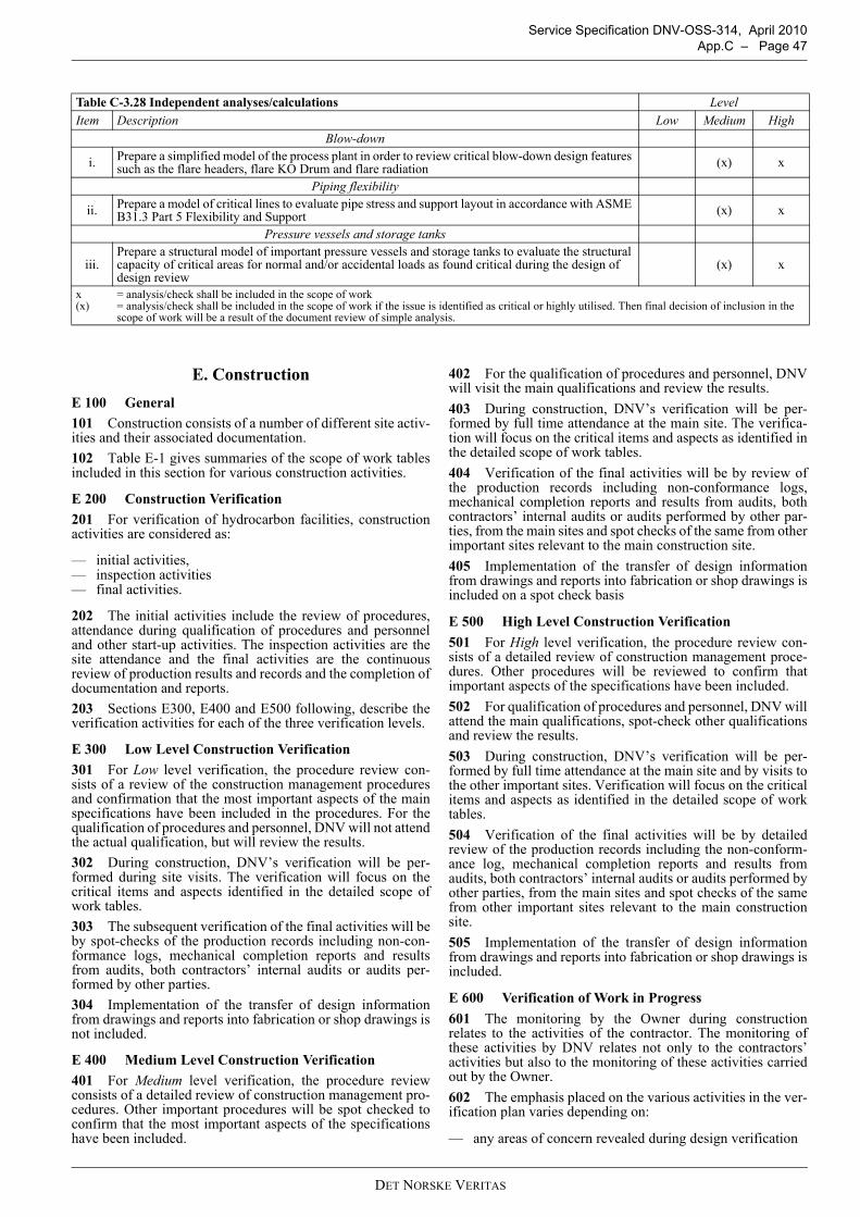
Service Specification DNV-OSS-314, April 2010 App.C – Page 47
E. ConstructionE 100 General101 Construction consists of a number of different site activ-ities and their associated documentation.102 Table E-1 gives summaries of the scope of work tablesincluded in this section for various construction activities.
E 200 Construction Verification201 For verification of hydrocarbon facilities, constructionactivities are considered as:
— initial activities,— inspection activities— final activities.
202 The initial activities include the review of procedures,attendance during qualification of procedures and personneland other start-up activities. The inspection activities are thesite attendance and the final activities are the continuousreview of production results and records and the completion ofdocumentation and reports.203 Sections E300, E400 and E500 following, describe theverification activities for each of the three verification levels.
E 300 Low Level Construction Verification301 For Low level verification, the procedure review con-sists of a review of the construction management proceduresand confirmation that the most important aspects of the mainspecifications have been included in the procedures. For thequalification of procedures and personnel, DNV will not attendthe actual qualification, but will review the results.302 During construction, DNV’s verification will be per-formed during site visits. The verification will focus on thecritical items and aspects identified in the detailed scope ofwork tables.303 The subsequent verification of the final activities will beby spot-checks of the production records including non-con-formance logs, mechanical completion reports and resultsfrom audits, both contractors’ internal audits or audits per-formed by other parties.304 Implementation of the transfer of design informationfrom drawings and reports into fabrication or shop drawings isnot included.
E 400 Medium Level Construction Verification401 For Medium level verification, the procedure reviewconsists of a detailed review of construction management pro-cedures. Other important procedures will be spot checked toconfirm that the most important aspects of the specificationshave been included.
402 For the qualification of procedures and personnel, DNVwill visit the main qualifications and review the results.403 During construction, DNV’s verification will be per-formed by full time attendance at the main site. The verifica-tion will focus on the critical items and aspects as identified inthe detailed scope of work tables.404 Verification of the final activities will be by review ofthe production records including non-conformance logs,mechanical completion reports and results from audits, bothcontractors’ internal audits or audits performed by other par-ties, from the main sites and spot checks of the same from otherimportant sites relevant to the main construction site.405 Implementation of the transfer of design informationfrom drawings and reports into fabrication or shop drawings isincluded on a spot check basis
E 500 High Level Construction Verification501 For High level verification, the procedure review con-sists of a detailed review of construction management proce-dures. Other procedures will be reviewed to confirm thatimportant aspects of the specifications have been included. 502 For qualification of procedures and personnel, DNV willattend the main qualifications, spot-check other qualificationsand review the results.503 During construction, DNV’s verification will be per-formed by full time attendance at the main site and by visits tothe other important sites. Verification will focus on the criticalitems and aspects as identified in the detailed scope of worktables.504 Verification of the final activities will be by detailedreview of the production records including the non-conform-ance log, mechanical completion reports and results fromaudits, both contractors’ internal audits or audits performed byother parties, from the main sites and spot checks of the samefrom other important sites relevant to the main constructionsite.505 Implementation of the transfer of design informationfrom drawings and reports into fabrication or shop drawings isincluded.
E 600 Verification of Work in Progress601 The monitoring by the Owner during constructionrelates to the activities of the contractor. The monitoring ofthese activities by DNV relates not only to the contractors’activities but also to the monitoring of these activities carriedout by the Owner.602 The emphasis placed on the various activities in the ver-ification plan varies depending on:
— any areas of concern revealed during design verification
Table C-3.28 Independent analyses/calculations LevelItem Description Low Medium High
Blow-down
i. Prepare a simplified model of the process plant in order to review critical blow-down design features such as the flare headers, flare KO Drum and flare radiation (x) x
Piping flexibility
ii. Prepare a model of critical lines to evaluate pipe stress and support layout in accordance with ASME B31.3 Part 5 Flexibility and Support (x) x
Pressure vessels and storage tanks
iii.Prepare a structural model of important pressure vessels and storage tanks to evaluate the structural capacity of critical areas for normal and/or accidental loads as found critical during the design of design review
(x) x
x = analysis/check shall be included in the scope of work(x) = analysis/check shall be included in the scope of work if the issue is identified as critical or highly utilised. Then final decision of inclusion in the
scope of work will be a result of the document review of simple analysis.
DET NORSKE VERITAS
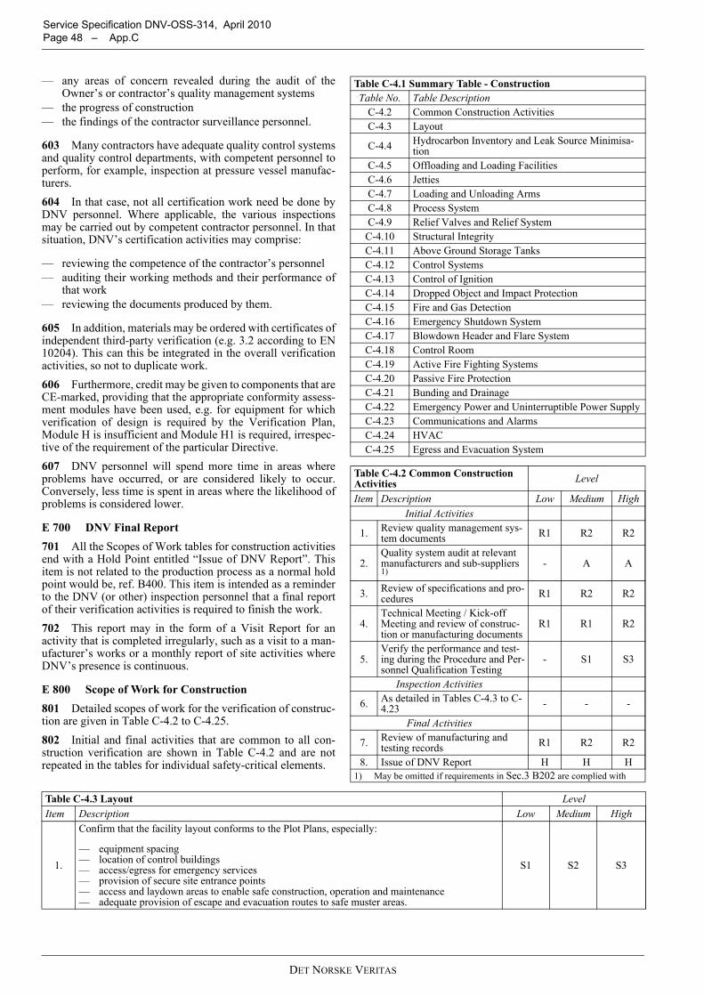
Service Specification DNV-OSS-314, April 2010 Page 48 – App.C
— any areas of concern revealed during the audit of theOwner’s or contractor’s quality management systems
— the progress of construction— the findings of the contractor surveillance personnel.
603 Many contractors have adequate quality control systemsand quality control departments, with competent personnel toperform, for example, inspection at pressure vessel manufac-turers.604 In that case, not all certification work need be done byDNV personnel. Where applicable, the various inspectionsmay be carried out by competent contractor personnel. In thatsituation, DNV’s certification activities may comprise:
— reviewing the competence of the contractor’s personnel— auditing their working methods and their performance of
that work— reviewing the documents produced by them.
605 In addition, materials may be ordered with certificates ofindependent third-party verification (e.g. 3.2 according to EN10204). This can this be integrated in the overall verificationactivities, so not to duplicate work.606 Furthermore, credit may be given to components that areCE-marked, providing that the appropriate conformity assess-ment modules have been used, e.g. for equipment for whichverification of design is required by the Verification Plan,Module H is insufficient and Module H1 is required, irrespec-tive of the requirement of the particular Directive.607 DNV personnel will spend more time in areas whereproblems have occurred, or are considered likely to occur.Conversely, less time is spent in areas where the likelihood ofproblems is considered lower.
E 700 DNV Final Report701 All the Scopes of Work tables for construction activitiesend with a Hold Point entitled “Issue of DNV Report”. Thisitem is not related to the production process as a normal holdpoint would be, ref. B400. This item is intended as a reminderto the DNV (or other) inspection personnel that a final reportof their verification activities is required to finish the work.702 This report may in the form of a Visit Report for anactivity that is completed irregularly, such as a visit to a man-ufacturer’s works or a monthly report of site activities whereDNV’s presence is continuous.
E 800 Scope of Work for Construction801 Detailed scopes of work for the verification of construc-tion are given in Table C-4.2 to C-4.25.802 Initial and final activities that are common to all con-struction verification are shown in Table C-4.2 and are notrepeated in the tables for individual safety-critical elements.
Table C-4.1 Summary Table - ConstructionTable No. Table Description
C-4.2 Common Construction ActivitiesC-4.3 Layout
C-4.4 Hydrocarbon Inventory and Leak Source Minimisa-tion
C-4.5 Offloading and Loading FacilitiesC-4.6 JettiesC-4.7 Loading and Unloading ArmsC-4.8 Process SystemC-4.9 Relief Valves and Relief System
C-4.10 Structural IntegrityC-4.11 Above Ground Storage TanksC-4.12 Control SystemsC-4.13 Control of IgnitionC-4.14 Dropped Object and Impact ProtectionC-4.15 Fire and Gas DetectionC-4.16 Emergency Shutdown SystemC-4.17 Blowdown Header and Flare SystemC-4.18 Control RoomC-4.19 Active Fire Fighting SystemsC-4.20 Passive Fire ProtectionC-4.21 Bunding and DrainageC-4.22 Emergency Power and Uninterruptible Power SupplyC-4.23 Communications and AlarmsC-4.24 HVACC-4.25 Egress and Evacuation System
Table C-4.2 Common Construction Activities Level
Item Description Low Medium HighInitial Activities
1. Review quality management sys-tem documents R1 R2 R2
2.Quality system audit at relevant manufacturers and sub-suppliers 1)
- A A
3. Review of specifications and pro-cedures R1 R2 R2
4.Technical Meeting / Kick-off Meeting and review of construc-tion or manufacturing documents
R1 R1 R2
5.Verify the performance and test-ing during the Procedure and Per-sonnel Qualification Testing
- S1 S3
Inspection Activities
6. As detailed in Tables C-4.3 to C-4.23 - - -
Final Activities
7. Review of manufacturing and testing records R1 R2 R2
8. Issue of DNV Report H H H1) May be omitted if requirements in Sec.3 B202 are complied with
Table C-4.3 Layout LevelItem Description Low Medium High
1.
Confirm that the facility layout conforms to the Plot Plans, especially:
— equipment spacing— location of control buildings— access/egress for emergency services— provision of secure site entrance points— access and laydown areas to enable safe construction, operation and maintenance— adequate provision of escape and evacuation routes to safe muster areas.
S1 S2 S3
DET NORSKE VERITAS
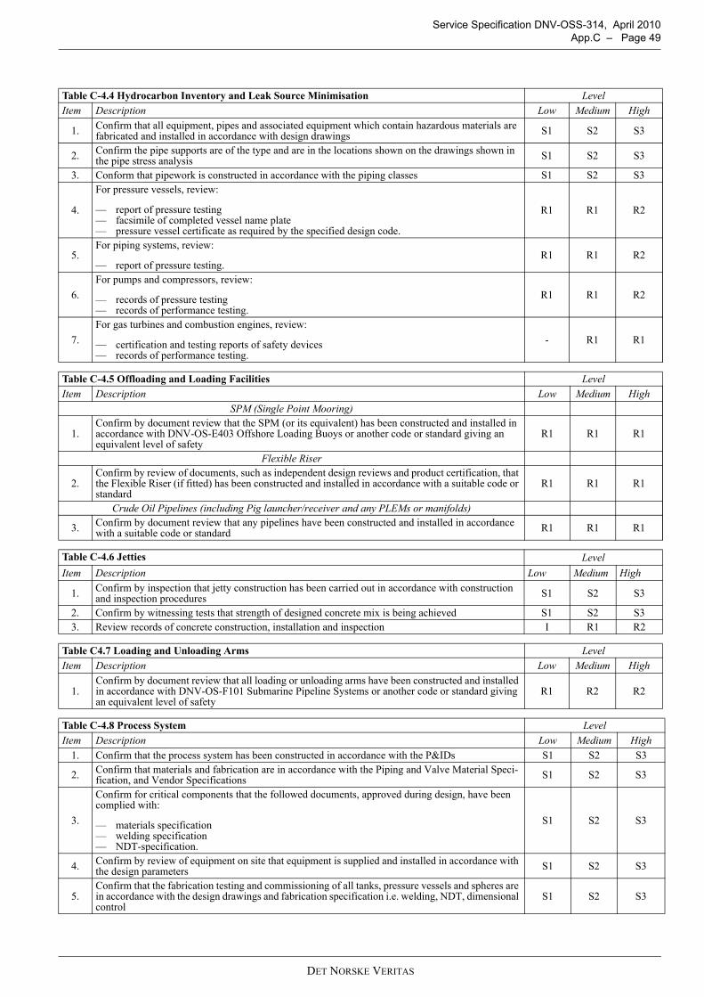
Service Specification DNV-OSS-314, April 2010 App.C – Page 49
Table C-4.4 Hydrocarbon Inventory and Leak Source Minimisation LevelItem Description Low Medium High
1. Confirm that all equipment, pipes and associated equipment which contain hazardous materials are fabricated and installed in accordance with design drawings S1 S2 S3
2. Confirm the pipe supports are of the type and are in the locations shown on the drawings shown in the pipe stress analysis S1 S2 S3
3. Conform that pipework is constructed in accordance with the piping classes S1 S2 S3
4.
For pressure vessels, review:
— report of pressure testing— facsimile of completed vessel name plate— pressure vessel certificate as required by the specified design code.
R1 R1 R2
5.For piping systems, review:
— report of pressure testing.R1 R1 R2
6.For pumps and compressors, review:
— records of pressure testing— records of performance testing.
R1 R1 R2
7.For gas turbines and combustion engines, review:
— certification and testing reports of safety devices— records of performance testing.
- R1 R1
Table C-4.5 Offloading and Loading Facilities LevelItem Description Low Medium High
SPM (Single Point Mooring)
1.Confirm by document review that the SPM (or its equivalent) has been constructed and installed in accordance with DNV-OS-E403 Offshore Loading Buoys or another code or standard giving an equivalent level of safety
R1 R1 R1
Flexible Riser
2.Confirm by review of documents, such as independent design reviews and product certification, that the Flexible Riser (if fitted) has been constructed and installed in accordance with a suitable code or standard
R1 R1 R1
Crude Oil Pipelines (including Pig launcher/receiver and any PLEMs or manifolds)
3. Confirm by document review that any pipelines have been constructed and installed in accordance with a suitable code or standard R1 R1 R1
Table C-4.6 Jetties LevelItem Description Low Medium High
1. Confirm by inspection that jetty construction has been carried out in accordance with construction and inspection procedures S1 S2 S3
2. Confirm by witnessing tests that strength of designed concrete mix is being achieved S1 S2 S33. Review records of concrete construction, installation and inspection I R1 R2
Table C4.7 Loading and Unloading Arms LevelItem Description Low Medium High
1.Confirm by document review that all loading or unloading arms have been constructed and installed in accordance with DNV-OS-F101 Submarine Pipeline Systems or another code or standard giving an equivalent level of safety
R1 R2 R2
Table C-4.8 Process System LevelItem Description Low Medium High
1. Confirm that the process system has been constructed in accordance with the P&IDs S1 S2 S3
2. Confirm that materials and fabrication are in accordance with the Piping and Valve Material Speci-fication, and Vendor Specifications S1 S2 S3
3.
Confirm for critical components that the followed documents, approved during design, have been complied with:
— materials specification — welding specification— NDT-specification.
S1 S2 S3
4. Confirm by review of equipment on site that equipment is supplied and installed in accordance with the design parameters S1 S2 S3
5.Confirm that the fabrication testing and commissioning of all tanks, pressure vessels and spheres are in accordance with the design drawings and fabrication specification i.e. welding, NDT, dimensional control
S1 S2 S3
DET NORSKE VERITAS
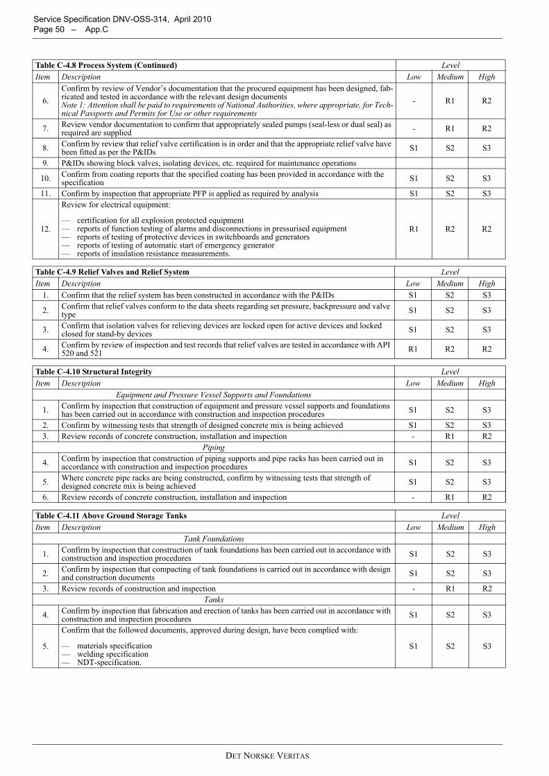
Service Specification DNV-OSS-314, April 2010 Page 50 – App.C
6.Confirm by review of Vendor’s documentation that the procured equipment has been designed, fab-ricated and tested in accordance with the relevant design documentsNote 1: Attention shall be paid to requirements of National Authorities, where appropriate, for Tech-nical Passports and Permits for Use or other requirements
- R1 R2
7. Review vendor documentation to confirm that appropriately sealed pumps (seal-less or dual seal) as required are supplied - R1 R2
8. Confirm by review that relief valve certification is in order and that the appropriate relief valve have been fitted as per the P&IDs S1 S2 S3
9. P&IDs showing block valves, isolating devices, etc. required for maintenance operations
10. Confirm from coating reports that the specified coating has been provided in accordance with the specification S1 S2 S3
11. Confirm by inspection that appropriate PFP is applied as required by analysis S1 S2 S3
12.
Review for electrical equipment:
— certification for all explosion protected equipment— reports of function testing of alarms and disconnections in pressurised equipment— reports of testing of protective devices in switchboards and generators— reports of testing of automatic start of emergency generator— reports of insulation resistance measurements.
R1 R2 R2
Table C-4.9 Relief Valves and Relief System LevelItem Description Low Medium High
1. Confirm that the relief system has been constructed in accordance with the P&IDs S1 S2 S3
2. Confirm that relief valves conform to the data sheets regarding set pressure, backpressure and valve type S1 S2 S3
3. Confirm that isolation valves for relieving devices are locked open for active devices and locked closed for stand-by devices S1 S2 S3
4. Confirm by review of inspection and test records that relief valves are tested in accordance with API 520 and 521 R1 R2 R2
Table C-4.10 Structural Integrity LevelItem Description Low Medium High
Equipment and Pressure Vessel Supports and Foundations
1. Confirm by inspection that construction of equipment and pressure vessel supports and foundations has been carried out in accordance with construction and inspection procedures S1 S2 S3
2. Confirm by witnessing tests that strength of designed concrete mix is being achieved S1 S2 S33. Review records of concrete construction, installation and inspection - R1 R2
Piping
4. Confirm by inspection that construction of piping supports and pipe racks has been carried out in accordance with construction and inspection procedures S1 S2 S3
5. Where concrete pipe racks are being constructed, confirm by witnessing tests that strength of designed concrete mix is being achieved S1 S2 S3
6. Review records of concrete construction, installation and inspection - R1 R2
Table C-4.11 Above Ground Storage Tanks LevelItem Description Low Medium High
Tank Foundations
1. Confirm by inspection that construction of tank foundations has been carried out in accordance with construction and inspection procedures S1 S2 S3
2. Confirm by inspection that compacting of tank foundations is carried out in accordance with design and construction documents S1 S2 S3
3. Review records of construction and inspection - R1 R2Tanks
4. Confirm by inspection that fabrication and erection of tanks has been carried out in accordance with construction and inspection procedures S1 S2 S3
5.
Confirm that the followed documents, approved during design, have been complied with:
— materials specification — welding specification— NDT-specification.
S1 S2 S3
Table C-4.8 Process System (Continued) LevelItem Description Low Medium High
DET NORSKE VERITAS
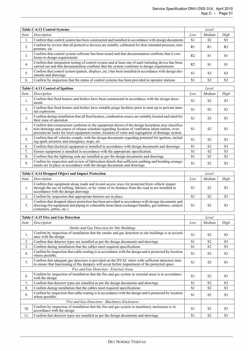
Service Specification DNV-OSS-314, April 2010 App.C – Page 51
Table C-4.12 Control Systems LevelItem Description Low Medium High
1. Confirm that control system has been constructed and installed in accordance with design documents S1 S2 S3
2. Confirm by review that all protective devices are suitably calibrated for their intended pressure, tem-perature, etc R1 R1 R2
3. Confirm that control system software has been tested and that documentation confirms that it con-forms to design requirements R2 S1 S1
4. Confirm that integration testing of control system and at least one of each initiating device has been carried out and that documentation confirms that the system conforms to design requirements R2 S1 S1
5. Confirm that control system (panels, displays, etc.) has been installed in accordance with design doc-uments and drawings S1 S2 S3
6. Confirm by inspection that the status of control systems has been provided at operator stations S1 S2 S3
Table C-4.13 Control of Ignition LevelItem Description Low Medium High
1. Confirm that fired heaters and boilers have been constructed in accordance with the design docu-ments S1 S2 S3
2. Confirm that fired heaters and boilers have suitable purge facilities prior to start-up to prevent inter-nal explosions S1 S2 S3
3. Confirm during installation that all fired heaters, combustion source are suitably located and rated for their zone of operation S1 S2 S3
4.Confirm that construction conforms to the equipment shown of the design hazardous area classifica-tion drawings and source of release schedule regarding location of ventilation inlets/outlets, over-pressure/air locks for local equipment rooms, location of vents and segregation of drainage system
S1 S2 S3
5. Confirm that all vehicles comply with the design documents regarding potential for ignition, includ-ing spark arrestors and emergency stops, etc S1 S2 S3
6. Confirm that electrical equipment is installed in accordance with design documents and drawings S1 S2 S37. Ensure equipment is installed in accordance with the appropriate specification. S1 S2 S38. Confirm that the lightning rods are installed as per the design documents and drawings S1 S2 S3
9. Confirm by inspection and review of fabrication details that sufficient earthing and bonding arrange-ments are in place in accordance with the design documents and drawings S1 S2 S3
Table C-4.14 Dropped Object and Impact Protection LevelItem Description Low Medium High
1.Confirm that equipment along roads and in-unit access ways for protected from vehicle impact through the use of curbing, barriers, or by virtue of its distance from the road in are installed in accordance with the design drawings
S1 S2 S3
2. Confirm by inspection that appropriate barriers are in place. S1 S2 S3
3.Confirm that dropped object protection has been provided in accordance with design documents and drawings for equipment and piping in vulnerable areas (heat exchanger bundles, gas turbines, catalyst containers, jetties, etc.)
S1 S2 S3
Table C-4.15 Fire and Gas Detection LevelItem Description Low Medium High
Smoke and Gas Detection for Site Buildings
1. Confirm by inspection of installation that the smoke and gas detection in site buildings is in accord-ance with the design S1 S2 S3
2. Confirm that detector types are installed as per the design documents and drawings S1 S2 S33. Confirm during installation that the cables meet required specifications S1 S2 S3
4. Confirm by inspection that cable routing is in accordance with the design and is protected by location where possible. S1 S2 S3
5. Confirm that adequate gas detection is provided on the HVAC inlets with sufficient detection time to ensure that functioning of the dampers will occur before impairment of the protected space S1 S2 S3
Fire and Gas Detection - External Areas
6. Confirm by inspection of installation that the fire and gas system in external areas is in accordance with the design S1 S2 S3
7. Confirm that detector types are installed as per the design documents and drawings S1 S2 S38. Confirm during installation that the cables meet required specifications S1 S2 S3
9. Confirm by inspection that cable routing is in accordance with the design and is protected by location where possible. S1 S2 S3
Fire and Gas Detection - Machinery Enclosures
10. Confirm by inspection of installation that the fire and gas system in machinery enclosures is in accordance with the design S1 S2 S3
11. Confirm that detector types are installed as per the design documents and drawings S1 S2 S3
DET NORSKE VERITAS
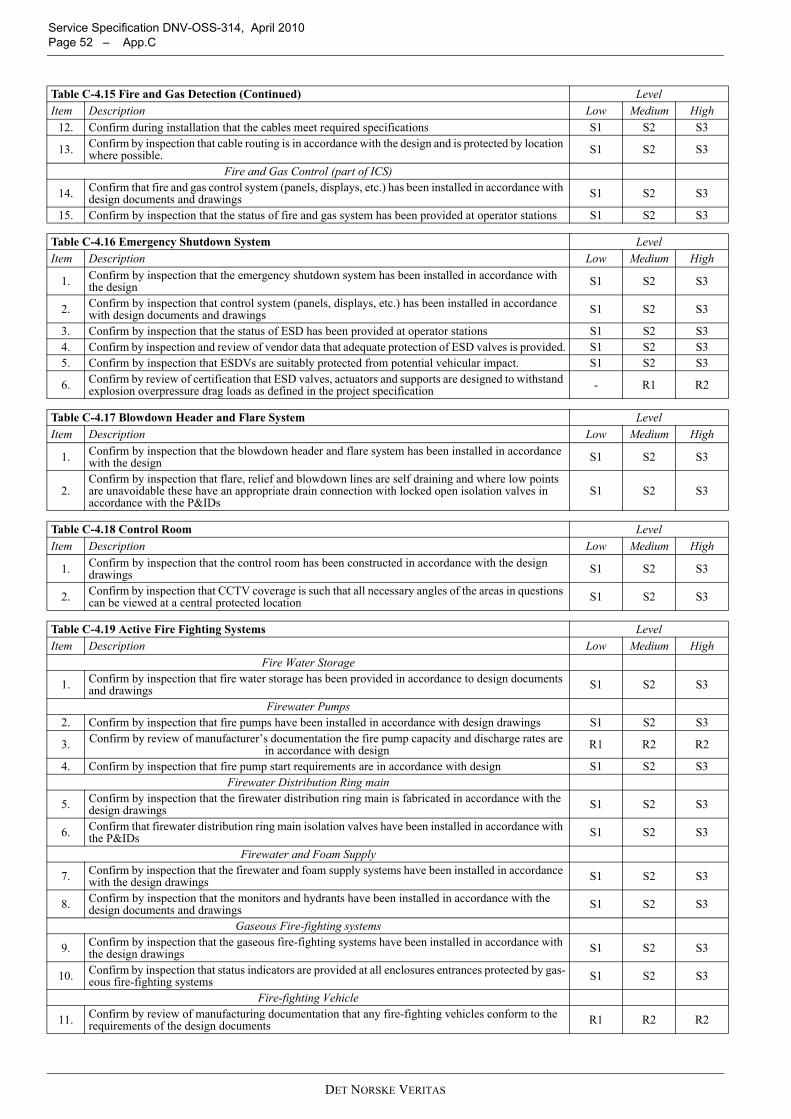
Service Specification DNV-OSS-314, April 2010 Page 52 – App.C
12. Confirm during installation that the cables meet required specifications S1 S2 S3
13. Confirm by inspection that cable routing is in accordance with the design and is protected by location where possible. S1 S2 S3
Fire and Gas Control (part of ICS)
14. Confirm that fire and gas control system (panels, displays, etc.) has been installed in accordance with design documents and drawings S1 S2 S3
15. Confirm by inspection that the status of fire and gas system has been provided at operator stations S1 S2 S3
Table C-4.16 Emergency Shutdown System LevelItem Description Low Medium High
1. Confirm by inspection that the emergency shutdown system has been installed in accordance with the design S1 S2 S3
2. Confirm by inspection that control system (panels, displays, etc.) has been installed in accordance with design documents and drawings S1 S2 S3
3. Confirm by inspection that the status of ESD has been provided at operator stations S1 S2 S34. Confirm by inspection and review of vendor data that adequate protection of ESD valves is provided. S1 S2 S35. Confirm by inspection that ESDVs are suitably protected from potential vehicular impact. S1 S2 S3
6. Confirm by review of certification that ESD valves, actuators and supports are designed to withstand explosion overpressure drag loads as defined in the project specification - R1 R2
Table C-4.17 Blowdown Header and Flare System LevelItem Description Low Medium High
1. Confirm by inspection that the blowdown header and flare system has been installed in accordance with the design S1 S2 S3
2.Confirm by inspection that flare, relief and blowdown lines are self draining and where low points are unavoidable these have an appropriate drain connection with locked open isolation valves in accordance with the P&IDs
S1 S2 S3
Table C-4.18 Control Room LevelItem Description Low Medium High
1. Confirm by inspection that the control room has been constructed in accordance with the design drawings S1 S2 S3
2. Confirm by inspection that CCTV coverage is such that all necessary angles of the areas in questions can be viewed at a central protected location S1 S2 S3
Table C-4.19 Active Fire Fighting Systems LevelItem Description Low Medium High
Fire Water Storage
1. Confirm by inspection that fire water storage has been provided in accordance to design documents and drawings S1 S2 S3
Firewater Pumps2. Confirm by inspection that fire pumps have been installed in accordance with design drawings S1 S2 S3
3. Confirm by review of manufacturer’s documentation the fire pump capacity and discharge rates are in accordance with design R1 R2 R2
4. Confirm by inspection that fire pump start requirements are in accordance with design S1 S2 S3Firewater Distribution Ring main
5. Confirm by inspection that the firewater distribution ring main is fabricated in accordance with the design drawings S1 S2 S3
6. Confirm that firewater distribution ring main isolation valves have been installed in accordance with the P&IDs S1 S2 S3
Firewater and Foam Supply
7. Confirm by inspection that the firewater and foam supply systems have been installed in accordance with the design drawings S1 S2 S3
8. Confirm by inspection that the monitors and hydrants have been installed in accordance with the design documents and drawings S1 S2 S3
Gaseous Fire-fighting systems
9. Confirm by inspection that the gaseous fire-fighting systems have been installed in accordance with the design drawings S1 S2 S3
10. Confirm by inspection that status indicators are provided at all enclosures entrances protected by gas-eous fire-fighting systems S1 S2 S3
Fire-fighting Vehicle
11. Confirm by review of manufacturing documentation that any fire-fighting vehicles conform to the requirements of the design documents R1 R2 R2
Table C-4.15 Fire and Gas Detection (Continued) LevelItem Description Low Medium High
DET NORSKE VERITAS
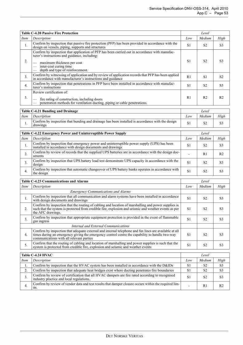
Service Specification DNV-OSS-314, April 2010 App.C – Page 53
Table C-4.20 Passive Fire Protection LevelItem Description Low Medium High
1. Confirm by inspection that passive fire protection (PFP) has been provided in accordance with the design on vessels, piping, supports and structures S1 S2 S3
2.
Confirm by inspection that application of PFP has been carried out in accordance with manufac-turer’s instructions and guidance, including:
— maximum thickness per coat— inter-coat curing time— depth and type of reinforcement.
S1 S2 S3
3. Confirm by witnessing of application and by review of application records that PFP has been applied in accordance with manufacturer’s instructions and guidance R1 S1 S2
4. Confirm by inspection that penetrations in PFP have been installed in accordance with manufac-turer’s instructions S1 S2 S3
5.Review certification of:
— fire rating of construction, including doors— penetration methods for ventilation ducting, piping or cable penetrations.
R1 R2 R2
Table C-4.21 Bunding and Drainage LevelItem Description Low Medium High
1. Confirm by inspection that bunding and drainage has been installed is accordance with the design drawings S1 S2 S3
Table C-4.22 Emergency Power and Uninterruptible Power Supply LevelItem Description Low Medium High
1. Confirm by inspection that emergency power and uninterruptible power supply (UPS) has been installed in accordance with design documents and drawings S1 S2 S3
2. Confirm by review of records that the supplied UPS batteries are in accordance with the design doc-uments - R1 R2
3. Confirm by inspection that UPS battery load test demonstrate UPS capacity in accordance with the design S1 S2 S3
4. Confirm by inspection that automatic changeover of UPS battery banks operates in accordance with the design S1 S2 S3
Table C-4.23 Communications and Alarms LevelItem Description Low Medium High
Emergency Communications and Alarms
1. Confirm by inspection that all communication and alarm systems have been installed in accordance with design documents and drawings S1 S2 S3
2.Confirm by inspection that the routing of cabling and location of marshalling and power supplies is such that the system is protected from credible fire, explosion and seismic and weather events as per the AFC drawings.
S1 S2 S3
3. Confirm by inspection that appropriate equipment protection is provided in the event of flammable gas ingress S1 S2 S3
Internal and External Communications
4.Confirm by inspection that adequate external and internal telephone and fax lines are available at all times during an emergency giving the emergency control centre the capability to handle two-way communications with all relevant parties
S1 S2 S3
5. Confirm that the routing of cabling and location of marshalling and power supplies is such that the system is protected from credible fire, explosion and seismic and weather events S1 S2 S3
Table C-4.24 HVAC LevelItem Description Low Medium High
1. Confirm by inspection that the HVAC system has been installed in accordance with the D&IDs S1 S2 S32. Confirm by inspection that adequate heat bridges exist where ducting penetrates fire boundaries S1 S2 S3
3. Confirm by review of certification that all HVAC dampers are fire rated according to recognised industry practice and local regulations. S1 S2 S3
4. Confirm by review of vendor data and test results that damper closure occurs within the required lim-its. - R1 R2
DET NORSKE VERITAS
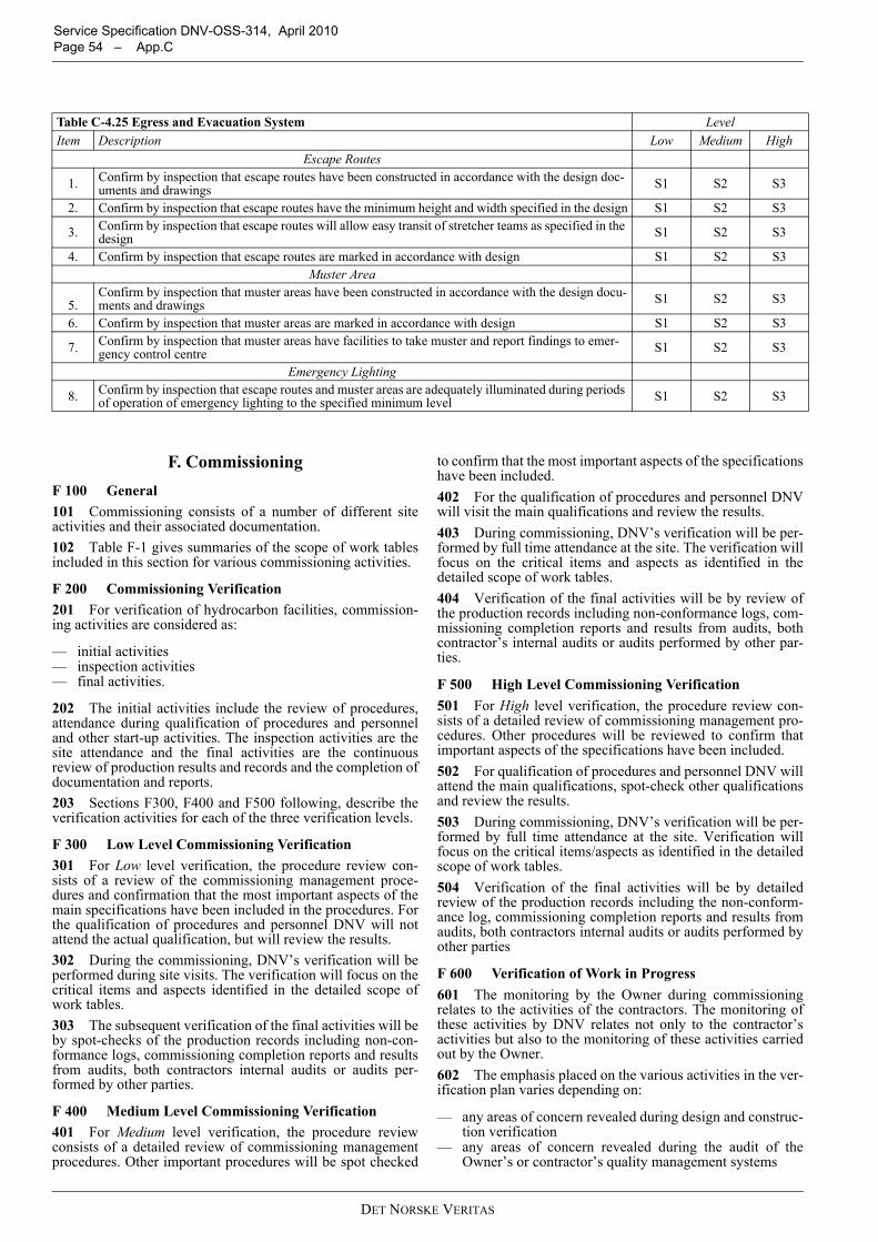
Service Specification DNV-OSS-314, April 2010 Page 54 – App.C
F. CommissioningF 100 General101 Commissioning consists of a number of different siteactivities and their associated documentation.102 Table F-1 gives summaries of the scope of work tablesincluded in this section for various commissioning activities.
F 200 Commissioning Verification201 For verification of hydrocarbon facilities, commission-ing activities are considered as:
— initial activities— inspection activities— final activities.
202 The initial activities include the review of procedures,attendance during qualification of procedures and personneland other start-up activities. The inspection activities are thesite attendance and the final activities are the continuousreview of production results and records and the completion ofdocumentation and reports.203 Sections F300, F400 and F500 following, describe theverification activities for each of the three verification levels.
F 300 Low Level Commissioning Verification301 For Low level verification, the procedure review con-sists of a review of the commissioning management proce-dures and confirmation that the most important aspects of themain specifications have been included in the procedures. Forthe qualification of procedures and personnel DNV will notattend the actual qualification, but will review the results.302 During the commissioning, DNV’s verification will beperformed during site visits. The verification will focus on thecritical items and aspects identified in the detailed scope ofwork tables.303 The subsequent verification of the final activities will beby spot-checks of the production records including non-con-formance logs, commissioning completion reports and resultsfrom audits, both contractors internal audits or audits per-formed by other parties.
F 400 Medium Level Commissioning Verification401 For Medium level verification, the procedure reviewconsists of a detailed review of commissioning managementprocedures. Other important procedures will be spot checked
to confirm that the most important aspects of the specificationshave been included.402 For the qualification of procedures and personnel DNVwill visit the main qualifications and review the results.403 During commissioning, DNV’s verification will be per-formed by full time attendance at the site. The verification willfocus on the critical items and aspects as identified in thedetailed scope of work tables.404 Verification of the final activities will be by review ofthe production records including non-conformance logs, com-missioning completion reports and results from audits, bothcontractor’s internal audits or audits performed by other par-ties.
F 500 High Level Commissioning Verification501 For High level verification, the procedure review con-sists of a detailed review of commissioning management pro-cedures. Other procedures will be reviewed to confirm thatimportant aspects of the specifications have been included.502 For qualification of procedures and personnel DNV willattend the main qualifications, spot-check other qualificationsand review the results.503 During commissioning, DNV’s verification will be per-formed by full time attendance at the site. Verification willfocus on the critical items/aspects as identified in the detailedscope of work tables.504 Verification of the final activities will be by detailedreview of the production records including the non-conform-ance log, commissioning completion reports and results fromaudits, both contractors internal audits or audits performed byother parties
F 600 Verification of Work in Progress601 The monitoring by the Owner during commissioningrelates to the activities of the contractors. The monitoring ofthese activities by DNV relates not only to the contractor’sactivities but also to the monitoring of these activities carriedout by the Owner.602 The emphasis placed on the various activities in the ver-ification plan varies depending on:
— any areas of concern revealed during design and construc-tion verification
— any areas of concern revealed during the audit of theOwner’s or contractor’s quality management systems
Table C-4.25 Egress and Evacuation System LevelItem Description Low Medium High
Escape Routes
1. Confirm by inspection that escape routes have been constructed in accordance with the design doc-uments and drawings S1 S2 S3
2. Confirm by inspection that escape routes have the minimum height and width specified in the design S1 S2 S3
3. Confirm by inspection that escape routes will allow easy transit of stretcher teams as specified in the design S1 S2 S3
4. Confirm by inspection that escape routes are marked in accordance with design S1 S2 S3Muster Area
5.Confirm by inspection that muster areas have been constructed in accordance with the design docu-ments and drawings S1 S2 S3
6. Confirm by inspection that muster areas are marked in accordance with design S1 S2 S3
7. Confirm by inspection that muster areas have facilities to take muster and report findings to emer-gency control centre S1 S2 S3
Emergency Lighting
8. Confirm by inspection that escape routes and muster areas are adequately illuminated during periods of operation of emergency lighting to the specified minimum level S1 S2 S3
DET NORSKE VERITAS
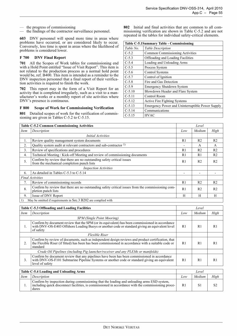
Service Specification DNV-OSS-314, April 2010 App.C – Page 55
— the progress of commissioning— the findings of the contractor surveillance personnel.
603 DNV personnel will spend more time in areas whereproblems have occurred, or are considered likely to occur.Conversely, less time is spent in areas where the likelihood ofproblems is considered lower.
F 700 DNV Final Report701 All the Scopes of Work tables for commissioning endwith a Hold Point entitled “Issue of Visit Report”. This item isnot related to the production process as a normal hold pointwould be, ref. B400. This item is intended as a reminder to theDNV inspection personnel that a final report of their verifica-tion activities is required to finish the work.702 This report may in the form of a Visit Report for anactivity that is completed irregularly, such as a visit to a man-ufacturer’s works or a monthly report of site activities whereDNV’s presence is continuous.
F 800 Scope of Work for Commissioning Verification801 Detailed scopes of work for the verification of commis-sioning are given in Tables C-5.2 to C-5.15.
802 Initial and final activities that are common to all com-missioning verification are shown in Table C-5.2 and are notrepeated in the tables for individual safety-critical elements.
Table C-5.1Summary Table - CommissioningTable No. Table DescriptionC-5.2 Common Commissioning ActivitiesC-5.3 Offloading and Loading FacilitiesC-5.4 Loading and Unloading ArmsC-5.5 Process SystemC-5.6 Control SystemsC-5.7 Control of IgnitionC-5.8 Fire and Gas DetectionC-5.9 Emergency Shutdown SystemC-5.10 Blowdown Header and Flare SystemC-5.11 Control RoomC-5.12 Active Fire Fighting SystemsC-5.13 Emergency Power and Uninterruptible Power SupplyC-5.14 CommunicationsC-5.15 HVAC
Table C-5.2 Common Commissioning Activities LevelItem Description Low Medium High
Initial Activities1. Review quality management system documents R1 R2 R22. Quality system audit at relevant contractors and sub-contractor 1) - A A3. Review of specifications and procedures R1 R2 R24. Technical Meeting / Kick-off Meeting and review of commissioning documents R1 R1 R2
5. Confirm by review that there are no outstanding safety critical issues from the mechanical completion punch lists R1 R2 R2
Inspection Activities6. As detailed in Tables C-5.3 to C-5.14 - - -
Final Activities7. Review of commissioning records R1 R2 R2
8. Confirm by review that there are no outstanding safety critical issues from the commissioning com-pletion punch lists R1 R2 R2
9. Issue of DNV Report H H H1) May be omitted if requirements in Sec.3 B202 are complied with
Table C-5.3 Offloading and Loading Facilities LevelItem Description Low Medium High
SPM (Single Point Mooring)
1.Confirm by document review that the SPM (or its equivalent) has been commissioned in accordance with DNV-OS-E403 Offshore Loading Buoys or another code or standard giving an equivalent level of safety
R1 R1 R1
Flexible Riser
2.Confirm by review of documents, such as independent design reviews and product certification, that the Flexible Riser (if fitted) has been has been commissioned in accordance with a suitable code or standard
R1 R1 R1
Crude Oil Pipelines (including Pig launcher/receiver and any PLEMs or manifolds)
3.Confirm by document review that any pipelines have been has been commissioned in accordance with DNV-OS-F101 Submarine Pipeline Systems or another code or standard giving an equivalent level of safety
R1 R1 R1
Table C-5.4 Loading and Unloading Arms LevelItem Description Low Medium High
1.Confirm by inspection during commissioning that the loading and unloading arms ESD system, including quick disconnect facilities, is commissioned in accordance with the commissioning proce-dures
R1 S1 S2
DET NORSKE VERITAS
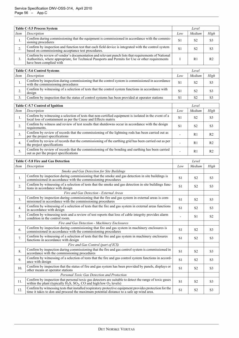
Service Specification DNV-OSS-314, April 2010 Page 56 – App.C
Table C-5.5 Process System LevelItem Description Low Medium High
1. Confirm during commissioning that the equipment is commissioned in accordance with the commis-sioning procedures S1 S2 S3
2. Confirm by inspection and function test that each field device is integrated with the control system based on commissioning acceptance test procedures. S1 S2 S3
3.Confirm by review of vendor’s documentation and relevant punch lists that requirements of National Authorities, where appropriate, for Technical Passports and Permits for Use or other requirements have been complied with
I R1 R2
Table C-5.6 Control Systems LevelItem Description Low Medium High
1. Confirm by inspection during commissioning that the control system is commissioned in accordance with the commissioning procedures S1 S2 S3
2. Confirm by witnessing of a selection of tests that the control system functions in accordance with design S1 S2 S3
3. Confirm by inspection that the status of control systems has been provided at operator stations S1 S2 S3
Table C-5.7 Control of Ignition LevelItem Description Low Medium High
1. Confirm by witnessing a selection of tests that non-certified equipment is isolated in the event of a local loss of containment as per the Cause and Effects matrix S1 S2 S3
2. Confirm by witness and review of test results that shutdowns occur in accordance with the design requirements. S1 S2 S3
3. Confirm by review of records that the commissioning of the lightning rods has been carried out as per the project specifications - R1 R2
4. Confirm by review of records that the commissioning of the earthing grid has been carried out as per the project specifications - R1 R2
5. Confirm by review of records that the commissioning of the bonding and earthing has been carried out as per the project specifications - R1 R2
Table C-5.8 Fire and Gas Detection LevelItem Description Low Medium High
Smoke and Gas Detection for Site Buildings
1. Confirm by inspection during commissioning that the smoke and gas detection in site buildings is commissioned in accordance with the commissioning procedures S1 S2 S3
2. Confirm by witnessing of a selection of tests that the smoke and gas detection in site buildings func-tions in accordance with design S1 S2 S3
Fire and Gas Detection - External Areas
3. Confirm by inspection during commissioning that the fire and gas system in external areas is com-missioned in accordance with the commissioning procedures S1 S2 S3
4. Confirm by witnessing of a selection of tests that the fire and gas system in external areas functions in accordance with design S1 S2 S3
5. Confirm by witnessing tests and a review of test reports that loss of cable integrity provides alarm condition in the control room. - S1 S2
Fire and Gas Detection - Machinery Enclosures
6. Confirm by inspection during commissioning that fire and gas system in machinery enclosures is commissioned in accordance with the commissioning procedures S1 S2 S3
7. Confirm by witnessing of a selection of tests that the fire and gas system in machinery enclosures functions in accordance with design S1 S2 S3
Fire and Gas Control (part of ICS)
8. Confirm by inspection during commissioning that the fire and gas control system is commissioned in accordance with the commissioning procedures S1 S2 S3
9. Confirm by witnessing of a selection of tests that the fire and gas control system functions in accord-ance with design S1 S2 S3
10. Confirm by inspection that the status of fire and gas system has been provided by panels, displays or other means at operator stations S1 S2 S3
Personal Toxic Gas Detection and Protection
11. Confirm by inspection that personal toxic gas detectors are suitable to detect the range of toxic gases within the plant (typically H2S, SO2, CO and high/low O2 levels) S1 S2 S3
12. Confirm by witnessing tests that installed respiratory protective equipment provides protection for the time it takes to don and proceed the maximum potential distance to a safe up-wind area. S1 S2 S3
DET NORSKE VERITAS
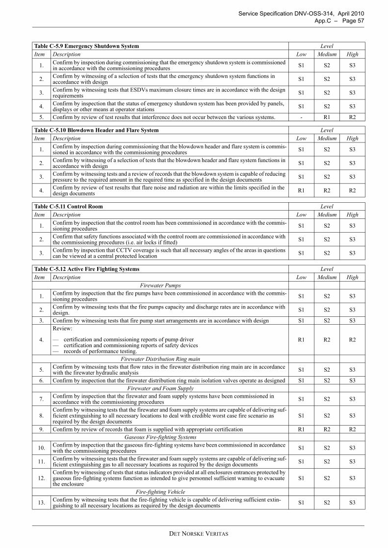
Service Specification DNV-OSS-314, April 2010 App.C – Page 57
Table C-5.9 Emergency Shutdown System LevelItem Description Low Medium High
1. Confirm by inspection during commissioning that the emergency shutdown system is commissioned in accordance with the commissioning procedures S1 S2 S3
2. Confirm by witnessing of a selection of tests that the emergency shutdown system functions in accordance with design S1 S2 S3
3. Confirm by witnessing tests that ESDVs maximum closure times are in accordance with the design requirements S1 S2 S3
4. Confirm by inspection that the status of emergency shutdown system has been provided by panels, displays or other means at operator stations S1 S2 S3
5. Confirm by review of test results that interference does not occur between the various systems. - R1 R2
Table C-5.10 Blowdown Header and Flare System LevelItem Description Low Medium High
1. Confirm by inspection during commissioning that the blowdown header and flare system is commis-sioned in accordance with the commissioning procedures S1 S2 S3
2. Confirm by witnessing of a selection of tests that the blowdown header and flare system functions in accordance with design S1 S2 S3
3. Confirm by witnessing tests and a review of records that the blowdown system is capable of reducing pressure to the required amount in the required time as specified in the design documents S1 S2 S3
4. Confirm by review of test results that flare noise and radiation are within the limits specified in the design documents R1 R2 R2
Table C-5.11 Control Room LevelItem Description Low Medium High
1. Confirm by inspection that the control room has been commissioned in accordance with the commis-sioning procedures S1 S2 S3
2. Confirm that safety functions associated with the control room are commissioned in accordance with the commissioning procedures (i.e. air locks if fitted) S1 S2 S3
3. Confirm by inspection that CCTV coverage is such that all necessary angles of the areas in questions can be viewed at a central protected location S1 S2 S3
Table C-5.12 Active Fire Fighting Systems LevelItem Description Low Medium High
Firewater Pumps
1. Confirm by inspection that the fire pumps have been commissioned in accordance with the commis-sioning procedures S1 S2 S3
2. Confirm by witnessing tests that the fire pumps capacity and discharge rates are in accordance with design. S1 S2 S3
3. Confirm by witnessing tests that fire pump start arrangements are in accordance with design S1 S2 S3
4.
Review:
— certification and commissioning reports of pump driver— certification and commissioning reports of safety devices— records of performance testing.
R1 R2 R2
Firewater Distribution Ring main
5. Confirm by witnessing tests that flow rates in the firewater distribution ring main are in accordance with the firewater hydraulic analysis S1 S2 S3
6. Confirm by inspection that the firewater distribution ring main isolation valves operate as designed S1 S2 S3Firewater and Foam Supply
7. Confirm by inspection that the firewater and foam supply systems have been commissioned in accordance with the commissioning procedures S1 S2 S3
8.Confirm by witnessing tests that the firewater and foam supply systems are capable of delivering suf-ficient extinguishing to all necessary locations to deal with credible worst case fire scenario as required by the design documents
S1 S2 S3
9. Confirm by review of records that foam is supplied with appropriate certification R1 R2 R2Gaseous Fire-fighting Systems
10. Confirm by inspection that the gaseous fire-fighting systems have been commissioned in accordance with the commissioning procedures S1 S2 S3
11. Confirm by witnessing tests that the firewater and foam supply systems are capable of delivering suf-ficient extinguishing gas to all necessary locations as required by the design documents S1 S2 S3
12.Confirm by witnessing of tests that status indicators provided at all enclosures entrances protected by gaseous fire-fighting systems function as intended to give personnel sufficient warning to evacuate the enclosure
S1 S2 S3
Fire-fighting Vehicle
13. Confirm by witnessing tests that the fire-fighting vehicle is capable of delivering sufficient extin-guishing to all necessary locations as required by the design documents S1 S2 S3
DET NORSKE VERITAS
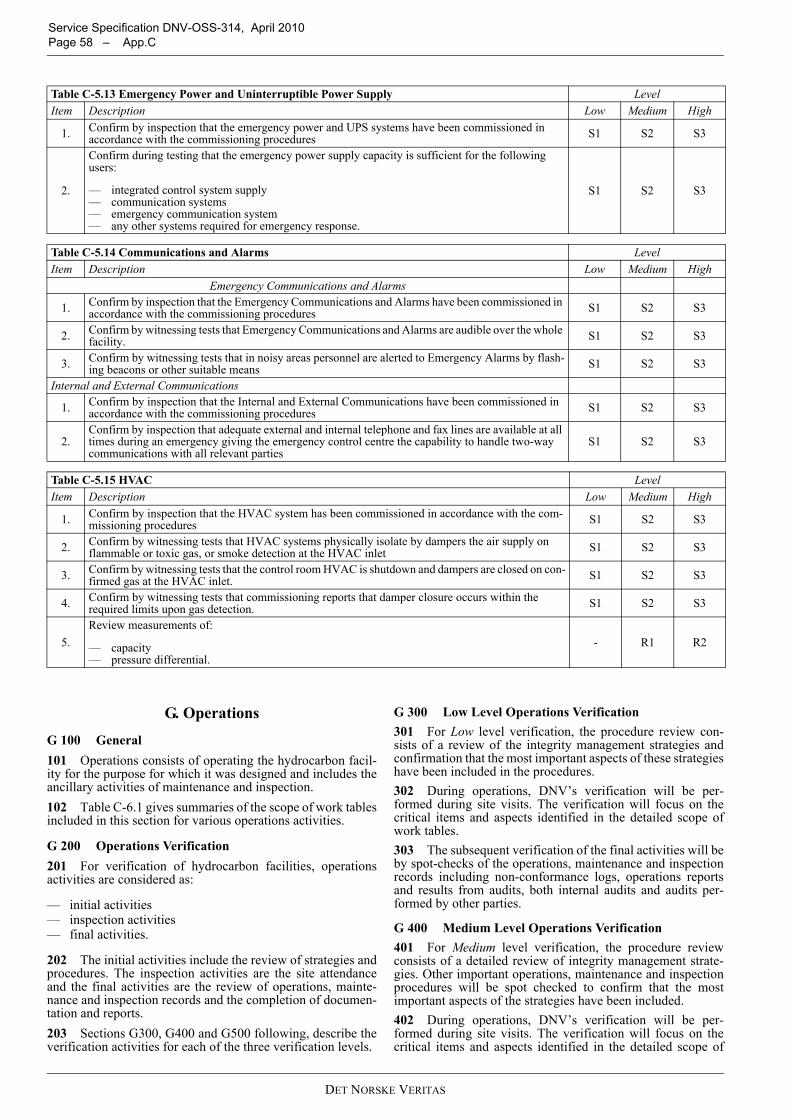
Service Specification DNV-OSS-314, April 2010 Page 58 – App.C
G. Operations
G 100 General101 Operations consists of operating the hydrocarbon facil-ity for the purpose for which it was designed and includes theancillary activities of maintenance and inspection.102 Table C-6.1 gives summaries of the scope of work tablesincluded in this section for various operations activities.
G 200 Operations Verification201 For verification of hydrocarbon facilities, operationsactivities are considered as:
— initial activities— inspection activities— final activities.
202 The initial activities include the review of strategies andprocedures. The inspection activities are the site attendanceand the final activities are the review of operations, mainte-nance and inspection records and the completion of documen-tation and reports.203 Sections G300, G400 and G500 following, describe theverification activities for each of the three verification levels.
G 300 Low Level Operations Verification301 For Low level verification, the procedure review con-sists of a review of the integrity management strategies andconfirmation that the most important aspects of these strategieshave been included in the procedures.302 During operations, DNV’s verification will be per-formed during site visits. The verification will focus on thecritical items and aspects identified in the detailed scope ofwork tables.303 The subsequent verification of the final activities will beby spot-checks of the operations, maintenance and inspectionrecords including non-conformance logs, operations reportsand results from audits, both internal audits and audits per-formed by other parties.
G 400 Medium Level Operations Verification401 For Medium level verification, the procedure reviewconsists of a detailed review of integrity management strate-gies. Other important operations, maintenance and inspectionprocedures will be spot checked to confirm that the mostimportant aspects of the strategies have been included.402 During operations, DNV’s verification will be per-formed during site visits. The verification will focus on thecritical items and aspects identified in the detailed scope of
Table C-5.13 Emergency Power and Uninterruptible Power Supply LevelItem Description Low Medium High
1. Confirm by inspection that the emergency power and UPS systems have been commissioned in accordance with the commissioning procedures S1 S2 S3
2.
Confirm during testing that the emergency power supply capacity is sufficient for the following users:
— integrated control system supply— communication systems— emergency communication system— any other systems required for emergency response.
S1 S2 S3
Table C-5.14 Communications and Alarms LevelItem Description Low Medium High
Emergency Communications and Alarms
1. Confirm by inspection that the Emergency Communications and Alarms have been commissioned in accordance with the commissioning procedures S1 S2 S3
2. Confirm by witnessing tests that Emergency Communications and Alarms are audible over the whole facility. S1 S2 S3
3. Confirm by witnessing tests that in noisy areas personnel are alerted to Emergency Alarms by flash-ing beacons or other suitable means S1 S2 S3
Internal and External Communications
1. Confirm by inspection that the Internal and External Communications have been commissioned in accordance with the commissioning procedures S1 S2 S3
2.Confirm by inspection that adequate external and internal telephone and fax lines are available at all times during an emergency giving the emergency control centre the capability to handle two-way communications with all relevant parties
S1 S2 S3
Table C-5.15 HVAC LevelItem Description Low Medium High
1. Confirm by inspection that the HVAC system has been commissioned in accordance with the com-missioning procedures S1 S2 S3
2. Confirm by witnessing tests that HVAC systems physically isolate by dampers the air supply on flammable or toxic gas, or smoke detection at the HVAC inlet S1 S2 S3
3. Confirm by witnessing tests that the control room HVAC is shutdown and dampers are closed on con-firmed gas at the HVAC inlet. S1 S2 S3
4. Confirm by witnessing tests that commissioning reports that damper closure occurs within the required limits upon gas detection. S1 S2 S3
5.Review measurements of:
— capacity— pressure differential.
- R1 R2
DET NORSKE VERITAS
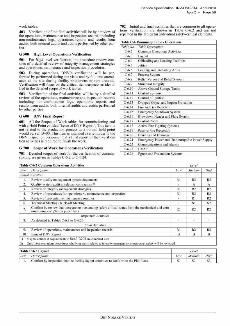
Service Specification DNV-OSS-314, April 2010 App.C – Page 59
work tables.403 Verification of the final activities will be by a review ofthe operations, maintenance and inspection records includingnon-conformance logs, operations reports and results fromaudits, both internal audits and audits performed by other par-ties.
G 500 High Level Operations Verification501 For High level verification, the procedure review con-sists of a detailed review of integrity management strategiesand operations, maintenance and inspection procedures.502 During operations, DNV’s verification will be per-formed by performed during site visits and by full time attend-ance at the site during facility shutdowns or turn-arounds.Verification will focus on the critical items/aspects as identi-fied in the detailed scope of work tables.503 Verification of the final activities will be by a detailedreview of the operations, maintenance and inspection recordsincluding non-conformance logs, operations reports andresults from audits, both internal audits and audits performedby other parties
G 600 DNV Final Report601 All the Scopes of Work tables for commissioning endwith a Hold Point entitled “Issue of DNV Report”. This item isnot related to the production process as a normal hold pointwould be, ref. B400. This item is intended as a reminder to theDNV inspection personnel that a final report of their verifica-tion activities is required to finish the work.
G 700 Scope of Work for Operations Verification701 Detailed scopes of work for the verification of commis-sioning are given in Tables C-6.2 to C-6.24.
702 Initial and final activities that are common to all opera-tions verification are shown in Table C-6.2 and are notrepeated in the tables for individual safety-critical elements.
Table C-6.1Summary Table - OperationsTable No. Table Description
C-6.2 Common Operations ActivitiesC-6.3 LayoutC-6.4 Offloading and Loading FacilitiesC-6.5 JettiesC-6.6 Loading and Unloading ArmsC-6.7 Process SystemC-6.8 Relief Valves and Relief SystemC-6.9 Structural Integrity
C-6.10 Above Ground Storage TanksC-6.11 Control SystemsC-6.12 Control of IgnitionC-6.13 Dropped Object and Impact ProtectionC-6.14 Fire and Gas DetectionC-6.15 Emergency Shutdown SystemC-6.16 Blowdown Header and Flare SystemC-6.17 Control RoomC-6.18 Active Fire Fighting SystemsC-6.19 Passive Fire ProtectionC-6.20 Bunding and DrainageC-6.21 Emergency Power and Uninterruptible Power SupplyC-6.22 Communications and AlarmsC-6.23 HVACC-6.24 Egress and Evacuation Systems
Table C-6.2 Common Operations Activities LevelItem Description Low Medium HighInitial Activities
1. Review quality management system documents R1 R2 R22. Quality system audit at relevant contractors 1) - A A3. Review of integrity management strategies R1 R2 R24. Review of procedures for operations 2), maintenance and inspection R1 R2 R25. Review of preventative maintenance routines - R1 R26. Technical Meeting / Kick-off Meeting - S1 S2
7. Confirm by review that there are no outstanding safety critical issues from the mechanical and com-missioning completion punch lists R1 R2 R2
Inspection Activities8. As detailed in Tables C-6.3 to C-6.26 - - -
Final Activities9. Review of operations, maintenance and inspection records R1 R2 R2
10. Issue of DNV Report H H H1) May be omitted if requirements in Sec.3 B202 are complied with2) Only those operations procedures wholly or partly related to integrity management or personnel safety will be reviewed
Table C-6.3 Layout LevelItem Description Low Medium High
1. Confirm by inspection that the facility layout continues to conform to the Plot Plans S1 S2 S3
DET NORSKE VERITAS

Service Specification DNV-OSS-314, April 2010 Page 60 – App.C
Table C-6.4 Offloading and Loading Facilities LevelItem Description Low Medium High
SPM (Single Point Mooring)
1. Confirm by inspection that the SPM (or its equivalent) remains in good condition with no leaks or mechanical damage observed S1 S2 S3
2. Confirm by document review that communication systems between the SPM and the refinery control room operate as designed R1 R1 R1
3. Confirm by document review of maintenance and inspection records that SPM remains in good con-dition R1 R2 R2
Flexible Riser
4. Confirm by review of documents that the Flexible Riser (if fitted) remains in good condition with no leaks or mechanical damage observed R1 R1 R1
Crude Oil Pipelines (including Pig launcher/receiver and any PLEMs or manifolds)
5. Confirm by inspection of the above-ground portions that any pipelines remain in good condition with no leaks or mechanical damage observed S1 S2 S3
6. Confirm by document review of maintenance and inspection records that any pipelines remain in good condition with no leaks or mechanical damage observed R1 R1 R1
7. Confirm by document review of potential readings that the pipelines cathodic protection systems are effective R1 R1 R1
Table C-6.5 Jetties LevelItem Description Low Medium High
1. Confirm by inspection that jetties remains in good condition with no mechanical damage observed S1 S2 S3
2. Confirm by document review of maintenance and inspection records that jetties remain in good con-dition and continue to operate as designed S1 S2 S3
Table C-6.6 Loading and Unloading Arms LevelItem Description Low Medium High
1. Confirm by inspection that all loading or unloading arms remain in good condition with no leaks or mechanical damage observed S1 S2 S3
2. Confirm by review of maintenance and inspection records that loading and unloading arms ESD sys-tem, including quick disconnect facilities continue to operate as designed R1 R2 R2
Table C-6.7 Process System LevelItem Description Low Medium High
1. Confirm by inspection that the process system remains constructed in accordance with the P&IDs S1 S2 S3Piping Systems
2.
Inspect for general condition and mechanical damage:
— check for obvious damage— check for incorrectly position, damaged or disturbed supports— check for bending and shearing of support foundation bolts, cracking of welded foundations or
displacement of supports— check saddle, sliding or roller bearing supports.
S1 S2 S3
3. Inspect surface coating or insulation to confirm that it is sealed at discontinuities S1 S2 S34. Inspect for signs of water ingress, where equipment potentially is liable to corrosion under insulation S1 S2 S35. Inspect small bore connections to confirm that they are adequately supported and not vibrating S1 S2 S36. Inspect the electrical insulation of non-ferrous pipework for deterioration S1 S2 S37. Inspect insulating gaskets between dissimilar metals for deterioration S1 S2 S3
8. Confirm by document review of maintenance and inspection records that piping systems remain in good condition with adequate wall thickness for the pressures contained within them R1 R2 R2
Pressure Vessels
9.
Inspect for general condition and mechanical damage:
— check for damage to shell, especially at attachments— check for damage to supports, especially at welds between supports and vessel and between sup-
ports and main beams.
S1 S2 S3
10. Inspect surface coating or insulation to confirm that it is sealed at discontinuities S1 S2 S311. Inspect for signs of water ingress, where equipment potentially is liable to corrosion under insulation S1 S2 S3
12. Inspect fitting and support of instruments to the vessel to confirm they are adequately supported and not vibrating S1 S2 S3
13. Inspect that the locking open or closed of isolation valves in relief and drain systems is in accordance with the process and instrumentation diagrams S1 S2 S3
14. Confirm by document review of maintenance and inspection records that pressure vessels remain in good condition with adequate wall thickness for the pressures contained within them R1 R2 R2
DET NORSKE VERITAS
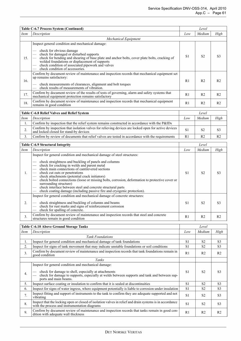
Service Specification DNV-OSS-314, April 2010 App.C – Page 61
Mechanical Equipment
15.
Inspect general condition and mechanical damage:
— check for obvious damage— check for damaged or disturbed supports— check for bending and shearing of base plate and anchor bolts, cover plate bolts, cracking of
welded foundations or displacement of supports— check condition of associated pipework and valves— check condition of accessories.
S1 S2 S3
16.
Confirm by document review of maintenance and inspection records that mechanical equipment set up remains satisfactory:
— check measurements of clearances, alignment and bolt torques— check results of measurements of vibration.
R1 R2 R2
17. Confirm by document review of the results of tests of governing, alarm and safety systems that mechanical equipment protection remains satisfactory R1 R2 R2
18. Confirm by document review of maintenance and inspection records that mechanical equipment remains in good condition R1 R2 R2
Table C-6.8 Relief Valves and Relief System LevelItem Description Low Medium High
1. Confirm by inspection that the relief system remains constructed in accordance with the P&IDs
2. Confirm by inspection that isolation valves for relieving devices are locked open for active devices and locked closed for stand-by devices S1 S2 S3
3. Confirm by review of documents that relief valves are tested in accordance with the requirements R1 R2 R2
Table C-6.9 Structural Integrity LevelItem Description Low Medium High
1.
Inspect for general condition and mechanical damage of steel structures:
— check straightness and buckling of panels and columns— check for cracking in welds and parent metal— check main connections of cantilevered sections— check cut outs or penetrations— check attachments (potential crack initiators)— check bolted connections (loose or missing bolts, corrosion, deformation to protective cover or
surrounding structure)— check interface between steel and concrete structural parts— check coating damage (including passive fire and cryogenic protection).
S1 S2 S3
2.
Inspect for general condition and mechanical damage of concrete structures:
— check straightness and buckling of columns and beams— check for rust marks and signs of reinforcement corrosion— check for spalling of concrete.
S1 S2 S3
3. Confirm by document review of maintenance and inspection records that steel and concrete structures remain in good condition R1 R2 R2
Table C-6.10 Above Ground Storage Tanks LevelItem Description Low Medium High
Tank Foundations1. Inspect for general condition and mechanical damage of tank foundations S1 S2 S32. Inspect for signs of tank movement that may indicate unstable foundations or soil conditions S1 S2 S3
3. Confirm by document review of maintenance and inspection records that tank foundations remain in good condition R1 R2 R2
Tanks
4.
Inspect for general condition and mechanical damage:
— check for damage to shell, especially at attachments— check for damage to supports, especially at welds between supports and tank and between sup-
ports and main beams.
S1 S2 S3
5. Inspect surface coating or insulation to confirm that it is sealed at discontinuities S1 S2 S36. Inspect for signs of water ingress, where equipment potentially is liable to corrosion under insulation S1 S2 S3
7. Inspect fitting and support of instruments to the tank to confirm they are adequate supported and not vibrating S1 S2 S3
8. Inspect that the locking open or closed of isolation valves in relief and drain systems is in accordance with the process and instrumentation diagrams S1 S2 S3
9. Confirm by document review of maintenance and inspection records that tanks remain in good con-dition with adequate wall thickness R1 R2 R2
Table C-6.7 Process System (Continued) LevelItem Description Low Medium High
DET NORSKE VERITAS
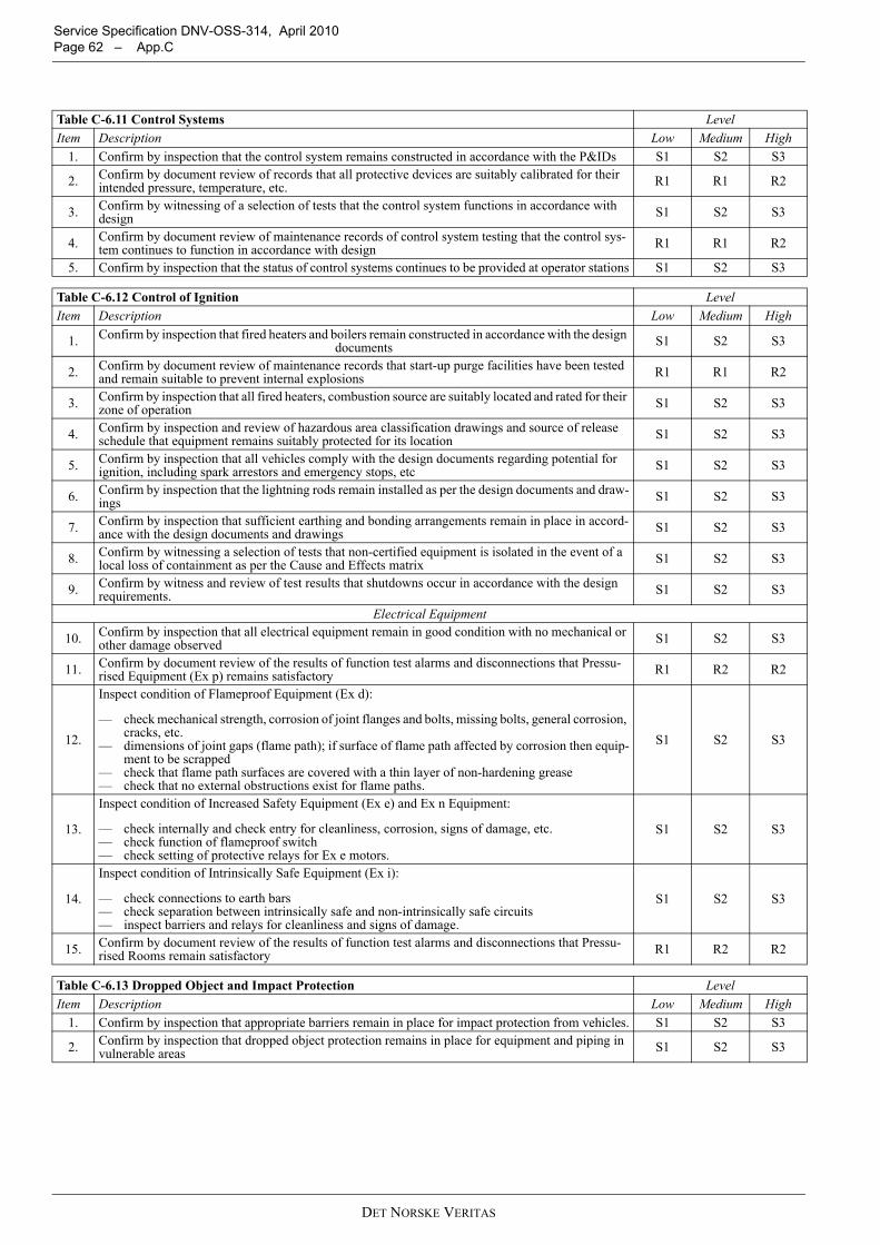
Service Specification DNV-OSS-314, April 2010 Page 62 – App.C
Table C-6.11 Control Systems LevelItem Description Low Medium High
1. Confirm by inspection that the control system remains constructed in accordance with the P&IDs S1 S2 S3
2. Confirm by document review of records that all protective devices are suitably calibrated for their intended pressure, temperature, etc. R1 R1 R2
3. Confirm by witnessing of a selection of tests that the control system functions in accordance with design S1 S2 S3
4. Confirm by document review of maintenance records of control system testing that the control sys-tem continues to function in accordance with design R1 R1 R2
5. Confirm by inspection that the status of control systems continues to be provided at operator stations S1 S2 S3
Table C-6.12 Control of Ignition LevelItem Description Low Medium High
1. Confirm by inspection that fired heaters and boilers remain constructed in accordance with the design documents S1 S2 S3
2. Confirm by document review of maintenance records that start-up purge facilities have been tested and remain suitable to prevent internal explosions R1 R1 R2
3. Confirm by inspection that all fired heaters, combustion source are suitably located and rated for their zone of operation S1 S2 S3
4. Confirm by inspection and review of hazardous area classification drawings and source of release schedule that equipment remains suitably protected for its location S1 S2 S3
5. Confirm by inspection that all vehicles comply with the design documents regarding potential for ignition, including spark arrestors and emergency stops, etc S1 S2 S3
6. Confirm by inspection that the lightning rods remain installed as per the design documents and draw-ings S1 S2 S3
7. Confirm by inspection that sufficient earthing and bonding arrangements remain in place in accord-ance with the design documents and drawings S1 S2 S3
8. Confirm by witnessing a selection of tests that non-certified equipment is isolated in the event of a local loss of containment as per the Cause and Effects matrix S1 S2 S3
9. Confirm by witness and review of test results that shutdowns occur in accordance with the design requirements. S1 S2 S3
Electrical Equipment
10. Confirm by inspection that all electrical equipment remain in good condition with no mechanical or other damage observed S1 S2 S3
11. Confirm by document review of the results of function test alarms and disconnections that Pressu-rised Equipment (Ex p) remains satisfactory R1 R2 R2
12.
Inspect condition of Flameproof Equipment (Ex d):
— check mechanical strength, corrosion of joint flanges and bolts, missing bolts, general corrosion, cracks, etc.
— dimensions of joint gaps (flame path); if surface of flame path affected by corrosion then equip-ment to be scrapped
— check that flame path surfaces are covered with a thin layer of non-hardening grease— check that no external obstructions exist for flame paths.
S1 S2 S3
13.
Inspect condition of Increased Safety Equipment (Ex e) and Ex n Equipment:
— check internally and check entry for cleanliness, corrosion, signs of damage, etc.— check function of flameproof switch— check setting of protective relays for Ex e motors.
S1 S2 S3
14.
Inspect condition of Intrinsically Safe Equipment (Ex i):
— check connections to earth bars— check separation between intrinsically safe and non-intrinsically safe circuits— inspect barriers and relays for cleanliness and signs of damage.
S1 S2 S3
15. Confirm by document review of the results of function test alarms and disconnections that Pressu-rised Rooms remain satisfactory R1 R2 R2
Table C-6.13 Dropped Object and Impact Protection LevelItem Description Low Medium High
1. Confirm by inspection that appropriate barriers remain in place for impact protection from vehicles. S1 S2 S3
2. Confirm by inspection that dropped object protection remains in place for equipment and piping in vulnerable areas S1 S2 S3
DET NORSKE VERITAS
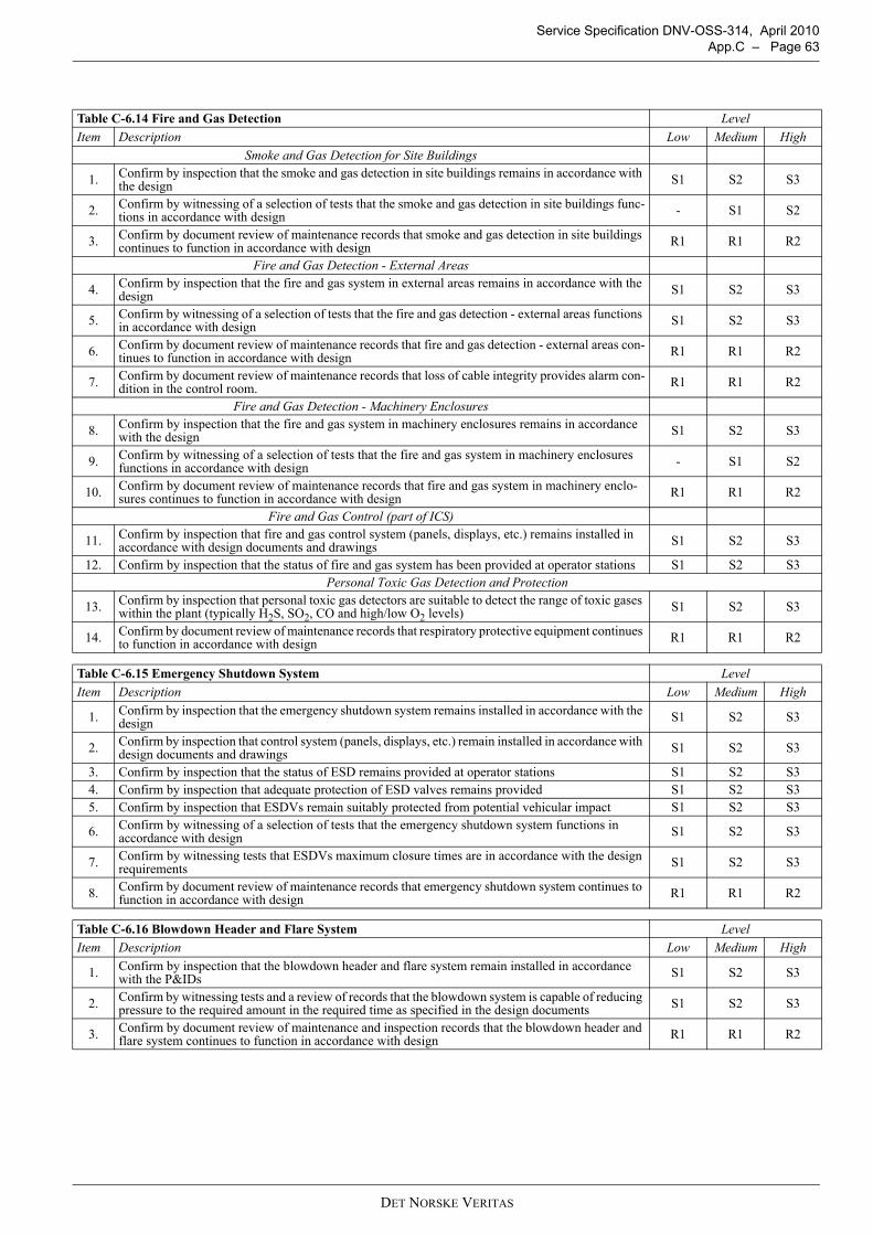
Service Specification DNV-OSS-314, April 2010 App.C – Page 63
Table C-6.14 Fire and Gas Detection LevelItem Description Low Medium High
Smoke and Gas Detection for Site Buildings
1. Confirm by inspection that the smoke and gas detection in site buildings remains in accordance with the design S1 S2 S3
2. Confirm by witnessing of a selection of tests that the smoke and gas detection in site buildings func-tions in accordance with design - S1 S2
3. Confirm by document review of maintenance records that smoke and gas detection in site buildings continues to function in accordance with design R1 R1 R2
Fire and Gas Detection - External Areas
4. Confirm by inspection that the fire and gas system in external areas remains in accordance with the design S1 S2 S3
5. Confirm by witnessing of a selection of tests that the fire and gas detection - external areas functions in accordance with design S1 S2 S3
6. Confirm by document review of maintenance records that fire and gas detection - external areas con-tinues to function in accordance with design R1 R1 R2
7. Confirm by document review of maintenance records that loss of cable integrity provides alarm con-dition in the control room. R1 R1 R2
Fire and Gas Detection - Machinery Enclosures
8. Confirm by inspection that the fire and gas system in machinery enclosures remains in accordance with the design S1 S2 S3
9. Confirm by witnessing of a selection of tests that the fire and gas system in machinery enclosures functions in accordance with design - S1 S2
10. Confirm by document review of maintenance records that fire and gas system in machinery enclo-sures continues to function in accordance with design R1 R1 R2
Fire and Gas Control (part of ICS)
11. Confirm by inspection that fire and gas control system (panels, displays, etc.) remains installed in accordance with design documents and drawings S1 S2 S3
12. Confirm by inspection that the status of fire and gas system has been provided at operator stations S1 S2 S3Personal Toxic Gas Detection and Protection
13. Confirm by inspection that personal toxic gas detectors are suitable to detect the range of toxic gases within the plant (typically H2S, SO2, CO and high/low O2 levels) S1 S2 S3
14. Confirm by document review of maintenance records that respiratory protective equipment continues to function in accordance with design R1 R1 R2
Table C-6.15 Emergency Shutdown System LevelItem Description Low Medium High
1. Confirm by inspection that the emergency shutdown system remains installed in accordance with the design S1 S2 S3
2. Confirm by inspection that control system (panels, displays, etc.) remain installed in accordance with design documents and drawings S1 S2 S3
3. Confirm by inspection that the status of ESD remains provided at operator stations S1 S2 S34. Confirm by inspection that adequate protection of ESD valves remains provided S1 S2 S35. Confirm by inspection that ESDVs remain suitably protected from potential vehicular impact S1 S2 S3
6. Confirm by witnessing of a selection of tests that the emergency shutdown system functions in accordance with design S1 S2 S3
7. Confirm by witnessing tests that ESDVs maximum closure times are in accordance with the design requirements S1 S2 S3
8. Confirm by document review of maintenance records that emergency shutdown system continues to function in accordance with design R1 R1 R2
Table C-6.16 Blowdown Header and Flare System LevelItem Description Low Medium High
1. Confirm by inspection that the blowdown header and flare system remain installed in accordance with the P&IDs S1 S2 S3
2. Confirm by witnessing tests and a review of records that the blowdown system is capable of reducing pressure to the required amount in the required time as specified in the design documents S1 S2 S3
3. Confirm by document review of maintenance and inspection records that the blowdown header and flare system continues to function in accordance with design R1 R1 R2
DET NORSKE VERITAS
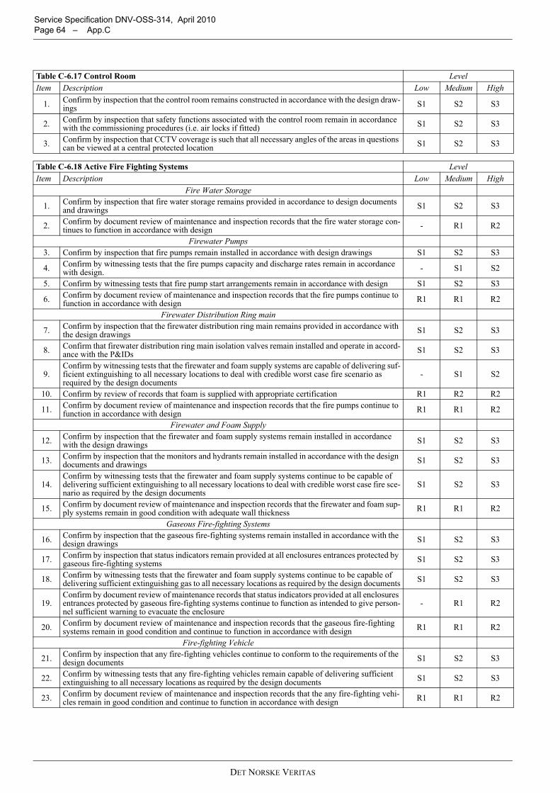
Service Specification DNV-OSS-314, April 2010 Page 64 – App.C
Table C-6.17 Control Room LevelItem Description Low Medium High
1. Confirm by inspection that the control room remains constructed in accordance with the design draw-ings S1 S2 S3
2. Confirm by inspection that safety functions associated with the control room remain in accordance with the commissioning procedures (i.e. air locks if fitted) S1 S2 S3
3. Confirm by inspection that CCTV coverage is such that all necessary angles of the areas in questions can be viewed at a central protected location S1 S2 S3
Table C-6.18 Active Fire Fighting Systems LevelItem Description Low Medium High
Fire Water Storage
1. Confirm by inspection that fire water storage remains provided in accordance to design documents and drawings S1 S2 S3
2. Confirm by document review of maintenance and inspection records that the fire water storage con-tinues to function in accordance with design - R1 R2
Firewater Pumps3. Confirm by inspection that fire pumps remain installed in accordance with design drawings S1 S2 S3
4. Confirm by witnessing tests that the fire pumps capacity and discharge rates remain in accordance with design. - S1 S2
5. Confirm by witnessing tests that fire pump start arrangements remain in accordance with design S1 S2 S3
6. Confirm by document review of maintenance and inspection records that the fire pumps continue to function in accordance with design R1 R1 R2
Firewater Distribution Ring main
7. Confirm by inspection that the firewater distribution ring main remains provided in accordance with the design drawings S1 S2 S3
8. Confirm that firewater distribution ring main isolation valves remain installed and operate in accord-ance with the P&IDs S1 S2 S3
9.Confirm by witnessing tests that the firewater and foam supply systems are capable of delivering suf-ficient extinguishing to all necessary locations to deal with credible worst case fire scenario as required by the design documents
- S1 S2
10. Confirm by review of records that foam is supplied with appropriate certification R1 R2 R2
11. Confirm by document review of maintenance and inspection records that the fire pumps continue to function in accordance with design R1 R1 R2
Firewater and Foam Supply
12. Confirm by inspection that the firewater and foam supply systems remain installed in accordance with the design drawings S1 S2 S3
13. Confirm by inspection that the monitors and hydrants remain installed in accordance with the design documents and drawings S1 S2 S3
14.Confirm by witnessing tests that the firewater and foam supply systems continue to be capable of delivering sufficient extinguishing to all necessary locations to deal with credible worst case fire sce-nario as required by the design documents
S1 S2 S3
15. Confirm by document review of maintenance and inspection records that the firewater and foam sup-ply systems remain in good condition with adequate wall thickness R1 R1 R2
Gaseous Fire-fighting Systems
16. Confirm by inspection that the gaseous fire-fighting systems remain installed in accordance with the design drawings S1 S2 S3
17. Confirm by inspection that status indicators remain provided at all enclosures entrances protected by gaseous fire-fighting systems S1 S2 S3
18. Confirm by witnessing tests that the firewater and foam supply systems continue to be capable of delivering sufficient extinguishing gas to all necessary locations as required by the design documents S1 S2 S3
19.Confirm by document review of maintenance records that status indicators provided at all enclosures entrances protected by gaseous fire-fighting systems continue to function as intended to give person-nel sufficient warning to evacuate the enclosure
- R1 R2
20. Confirm by document review of maintenance and inspection records that the gaseous fire-fighting systems remain in good condition and continue to function in accordance with design R1 R1 R2
Fire-fighting Vehicle
21. Confirm by inspection that any fire-fighting vehicles continue to conform to the requirements of the design documents S1 S2 S3
22. Confirm by witnessing tests that any fire-fighting vehicles remain capable of delivering sufficient extinguishing to all necessary locations as required by the design documents S1 S2 S3
23. Confirm by document review of maintenance and inspection records that the any fire-fighting vehi-cles remain in good condition and continue to function in accordance with design R1 R1 R2
DET NORSKE VERITAS
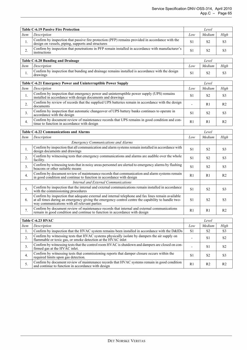
Service Specification DNV-OSS-314, April 2010 App.C – Page 65
Table C-6.19 Passive Fire Protection LevelItem Description Low Medium High
1. Confirm by inspection that passive fire protection (PFP) remains provided in accordance with the design on vessels, piping, supports and structures S1 S2 S3
2. Confirm by inspection that penetrations in PFP remain installed in accordance with manufacturer’s instructions S1 S2 S3
Table C-6.20 Bunding and Drainage LevelItem Description Low Medium High
1. Confirm by inspection that bunding and drainage remains installed is accordance with the design drawings S1 S2 S3
Table C-6.21 Emergency Power and Uninterruptible Power Supply LevelItem Description Low Medium High
1. Confirm by inspection that emergency power and uninterruptible power supply (UPS) remains installed in accordance with design documents and drawings S1 S2 S3
2. Confirm by review of records that the supplied UPS batteries remain in accordance with the design documents - R1 R2
3. Confirm by inspection that automatic changeover of UPS battery banks continues to operate in accordance with the design S1 S2 S3
4. Confirm by document review of maintenance records that UPS remains in good condition and con-tinue to function in accordance with design R1 R1 R2
Table C-6.22 Communications and Alarms LevelItem Description Low Medium High
Emergency Communications and Alarms
1. Confirm by inspection that all communication and alarm systems remain installed in accordance with design documents and drawings S1 S2 S3
2. Confirm by witnessing tests that emergency communications and alarms are audible over the whole facility. S1 S2 S3
3. Confirm by witnessing tests that in noisy areas personnel are alerted to emergency alarms by flashing beacons or other suitable means S1 S2 S3
4. Confirm by document review of maintenance records that communication and alarm systems remain in good condition and continue to function in accordance with design R1 R1 R2
Internal and External Communications
5. Confirm by inspection that the internal and external communications remain installed in accordance with the commissioning procedures S1 S2 S3
6.Confirm by inspection that adequate external and internal telephone and fax lines remain available at all times during an emergency giving the emergency control centre the capability to handle two-way communications with all relevant parties
S1 S2 S3
7. Confirm by document review of maintenance records that internal and external communications remain in good condition and continue to function in accordance with design R1 R1 R2
Table C-6.23 HVAC LevelItem Description Low Medium High
1. Confirm by inspection that the HVAC system remains been installed in accordance with the D&IDs S1 S2 S3
2. Confirm by witnessing tests that HVAC systems physically isolate by dampers the air supply on flammable or toxic gas, or smoke detection at the HVAC inlet - S1 S2
3. Confirm by witnessing tests that the control room HVAC is shutdown and dampers are closed on con-firmed gas at the HVAC inlet. - S1 S2
4. Confirm by witnessing tests that commissioning reports that damper closure occurs within the required limits upon gas detection. S1 S2 S3
5. Confirm by document review of maintenance records that HVAC systems remain in good condition and continue to function in accordance with design R1 R2 R2
DET NORSKE VERITAS
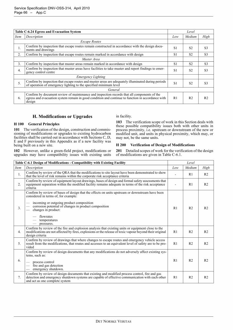
Service Specification DNV-OSS-314, April 2010 Page 66 – App.C
H. Modifications or UpgradesH 100 General Principles101 The verification of the design, construction and commis-sioning of modifications or upgrades to existing hydrocarbonfacilities shall be carried out in accordance with Sections C, D,E and F previously in this Appendix as if a new facility wasbeing built on a new site.102 However, unlike a green-field project, modifications orupgrades may have compatibility issues with existing units
in facility.103 The verification scope of work in this Section deals withthese possible compatibility issues both with other units inprocess proximity, i.e. upstream or downstream of the new ormodified unit, and units in physical proximity, which may, ormay not, be the same units.
H 200 Verification of Design of Modifications201 Detailed scopes of work for the verification of the designof modifications are given in Table C-6.1.
Table C-6.24 Egress and Evacuation System LevelItem Description Low Medium High
Escape Routes
1. Confirm by inspection that escape routes remain constructed in accordance with the design docu-ments and drawings S1 S2 S3
2. Confirm by inspection that escape routes remain marked in accordance with design S1 S2 S3Muster Area
3. Confirm by inspection that muster areas remain marked in accordance with design S1 S2 S3
4. Confirm by inspection that muster areas have facilities to take muster and report findings to emer-gency control centre S1 S2 S3
Emergency Lighting
5. Confirm by inspection that escape routes and muster areas are adequately illuminated during periods of operation of emergency lighting to the specified minimum level S1 S2 S3
General
6.Confirm by document review of maintenance and inspection records that all components of the egress and evacuation system remain in good condition and continue to function in accordance with design
R1 R2 R2
Table C-6.1 Design of Modifications - Compatibility with Existing Facility LevelItem Description Low Medium High
1. Confirm by review of the QRA that the modifications to site layout have been demonstrated to show that the level of risk remains within the corporate risk acceptance criteria - R1 R2
2.Confirm by review of equipment layout drawings, bases of design and formal safety assessments that equipment separation within the modified facility remains adequate in terms of the risk acceptance criteria
- R1 R2
3.
Confirm by review of bases of design that the effects on units upstream or downstream have been considered in terms of, for example:
— incoming or outgoing product composition— corrosion potential of changes in product composition— changes in product:
— flowrates— temperatures— pressures.
R1 R2 R2
4.Confirm by review of the fire and explosion analysis that existing units or equipment close to the modifications are not affected by fires, explosions or the release of toxic vapour beyond their original design criteria
R1 R2 R2
5.Confirm by review of drawings that where changes to escape routes and emergency vehicle access result from the modifications, that routes and accesses to an equivalent level of safety are to be pro-vided
R1 R2 R2
6.
Confirm by review of design documents that any modifications do not adversely affect existing sys-tems, such as:
— process control— fire and gas detection— emergency shutdown.
R1 R2 R2
7.Confirm by review of design documents that existing and modified process control, fire and gas detection and emergency shutdown systems are capable of effective communication with each other and act as one complete system
R1 R2 R2
DET NORSKE VERITAS
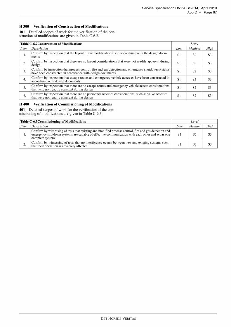
Service Specification DNV-OSS-314, April 2010 App.C – Page 67
H 300 Verification of Construction of Modifications301 Detailed scopes of work for the verification of the con-struction of modifications are given in Table C-6.2.
H 400 Verification of Commissioning of Modifications401 Detailed scopes of work for the verification of the com-missioning of modifications are given in Table C-6.3.
Table C-6.2Construction of Modifications LevelItem Description Low Medium High
1. Confirm by inspection that the layout of the modifications is in accordance with the design docu-ments S1 S2 S3
2. Confirm by inspection that there are no layout considerations that were not readily apparent during design S1 S2 S3
3. Confirm by inspection that process control, fire and gas detection and emergency shutdown systems have been constructed in accordance with design documents S1 S2 S3
4. Confirm by inspection that escape routes and emergency vehicle accesses have been constructed in accordance with design documents S1 S2 S3
5. Confirm by inspection that there are no escape routes and emergency vehicle access considerations that were not readily apparent during design S1 S2 S3
6. Confirm by inspection that there are no personnel accesses considerations, such as valve accesses, that were not readily apparent during design S1 S2 S3
Table C-6.3Commissioning of Modifications LevelItem Description Low Medium High
1.Confirm by witnessing of tests that existing and modified process control, fire and gas detection and emergency shutdown systems are capable of effective communication with each other and act as one complete system
S1 S2 S3
2. Confirm by witnessing of tests that no interference occurs between new and existing systems such that their operation is adversely affected S1 S2 S3
DET NORSKE VERITAS
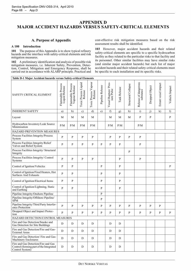
Service Specification DNV-OSS-314, April 2010 Page 68 – App.D
APPENDIX D MAJOR ACCIDENT HAZARDS VERSUS SAFETY-CRITICAL ELEMENTS
A. Purpose of AppendixA 100 Introduction101 The purpose of this Appendix is to show typical refineryhazards and the interface with safety-critical elements and riskmitigation measures.102 A preliminary identification and analysis of possible riskmitigation measures, i.e. Inherent Safety, Prevention, Detec-tion, Control, Mitigation and Emergency Response, shall becarried out in accordance with ALARP principle. Practical and
cost-effective risk mitigation measures based on the riskassessment results shall be identified.103 However, major accident hazards and their relatedsafety-critical elements are specific to a specific hydrocarbonfacility as they related to the particular risks to that facility andits personnel. Other similar facilities may have similar risks(and similar major accident hazards) but each list of majoraccident hazards and their related safety-critical elements mustbe specific to each installation and its specific risks.
Table D-1 Major Accident hazards versus Safety-critical Elements
SAFETY CRITICAL ELEMENT
Flam
mab
le P
roce
ss
Liqu
id R
elea
se
Flam
mab
le P
roce
ss
Vap
our R
elea
se
Toxi
c Pr
oces
s Liq
uid
Rel
ease
Toxi
c Pr
oces
s Vap
our
Rel
ease
Pipe
line
Rel
ease
Ves
sel R
uptu
re/ P
res-
sure
Pul
se
Tank
Rel
ease
Stru
ctur
al C
olla
pse
Rel
ease
of d
ange
rous
su
bsta
nce
Dro
pped
Obj
ect
Erra
nt v
esse
l im
pact
Veh
icle
Impa
ct
INHERENT SAFETY a) b) c) d) e) f) g) h) i) j) k) l)
Layout M M M M M M M P P P
Hydrocarbon Inventory/Leak Source Minimisation P/M P/M P/M P/M P/M P/M P/M
HAZARD PREVENTION MEASURESProcess Facilities Integrity/Process System P P P P P P P P
Process Facilities Integrity/Relief Valves and Relief System P P P P P P P P
Process Facilities Integrity/ Structural Integrity P
Process Facilities Integrity/ Control Systems P P P P P P
Control of Ignition/Vehicles P P P P P
Control of Ignition/Fired Heaters, Hot Surfaces And Exhausts P P P P
Control of Ignition/Electrical Items P P P P
Control of Ignition/Lightning, Static and Earthing P P P P
Pipeline Integrity/Onshore Pipeline PPipeline Integrity/Offshore Pipeline/SPM P
Pipeline Integrity/Third Party Interfer-ence Protection P P P P P P P P P P P
Dropped Object and Impact Protec-tion P P P P P P P P P P P P
HAZARD DETECTION/CONTROL MEASURESFire and Gas Detection/Smoke and Gas Detection for Site Buildings D D D D D D
Fire and Gas Detection/Fire and Gas-External Areas D D D D D D
Fire and Gas Detection/ Fire and Gas-Machinery Enclosures D D D D D D
Fire and Gas Detection/Fire and Gas Control (forming part of the Integrated Control System)
D D D D D D
DET NORSKE VERITAS
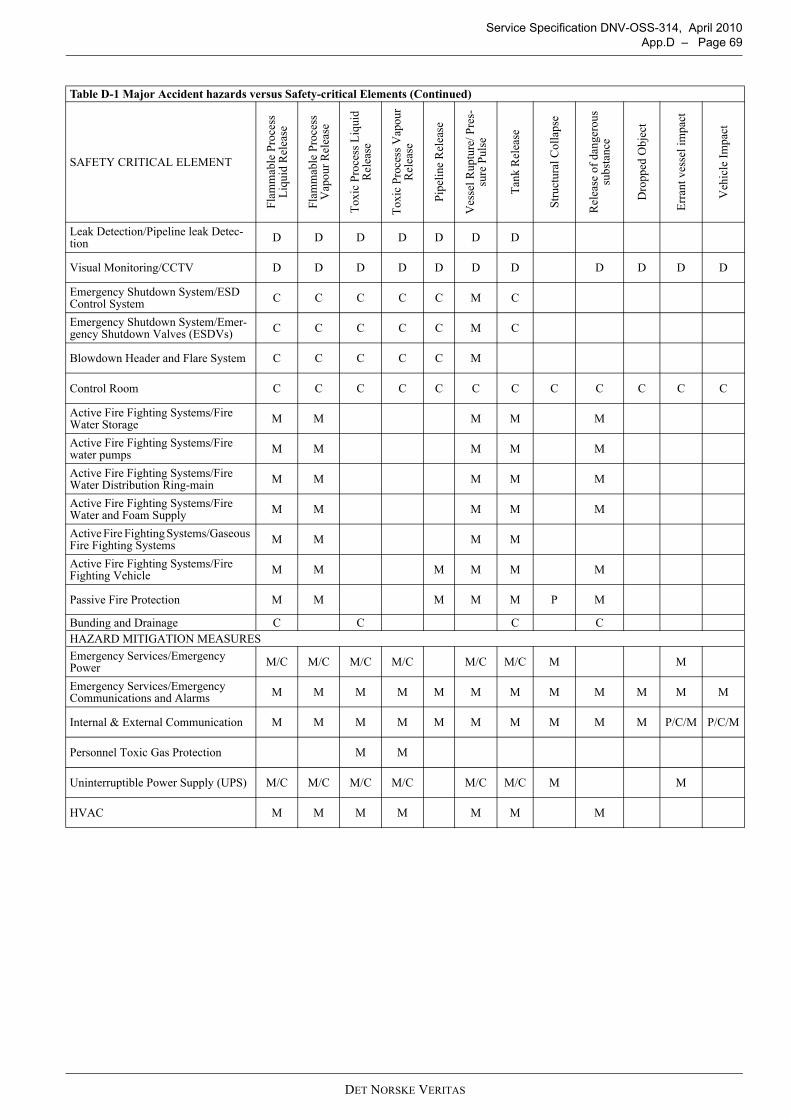
Service Specification DNV-OSS-314, April 2010 App.D – Page 69
Leak Detection/Pipeline leak Detec-tion D D D D D D D
Visual Monitoring/CCTV D D D D D D D D D D D
Emergency Shutdown System/ESD Control System C C C C C M C
Emergency Shutdown System/Emer-gency Shutdown Valves (ESDVs) C C C C C M C
Blowdown Header and Flare System C C C C C M
Control Room C C C C C C C C C C C C
Active Fire Fighting Systems/Fire Water Storage M M M M M
Active Fire Fighting Systems/Fire water pumps M M M M M
Active Fire Fighting Systems/Fire Water Distribution Ring-main M M M M M
Active Fire Fighting Systems/Fire Water and Foam Supply M M M M M
Active Fire Fighting Systems/Gaseous Fire Fighting Systems M M M M
Active Fire Fighting Systems/Fire Fighting Vehicle M M M M M M
Passive Fire Protection M M M M M P M
Bunding and Drainage C C C CHAZARD MITIGATION MEASURESEmergency Services/Emergency Power M/C M/C M/C M/C M/C M/C M M
Emergency Services/Emergency Communications and Alarms M M M M M M M M M M M M
Internal & External Communication M M M M M M M M M M P/C/M P/C/M
Personnel Toxic Gas Protection M M
Uninterruptible Power Supply (UPS) M/C M/C M/C M/C M/C M/C M M
HVAC M M M M M M M
Table D-1 Major Accident hazards versus Safety-critical Elements (Continued)
SAFETY CRITICAL ELEMENT
Flam
mab
le P
roce
ss
Liqu
id R
elea
se
Flam
mab
le P
roce
ss
Vap
our R
elea
se
Toxi
c Pr
oces
s Liq
uid
Rel
ease
Toxi
c Pr
oces
s Vap
our
Rel
ease
Pipe
line
Rel
ease
Ves
sel R
uptu
re/ P
res-
sure
Pul
se
Tank
Rel
ease
Stru
ctur
al C
olla
pse
Rel
ease
of d
ange
rous
su
bsta
nce
Dro
pped
Obj
ect
Erra
nt v
esse
l im
pact
Veh
icle
Impa
ct
DET NORSKE VERITAS
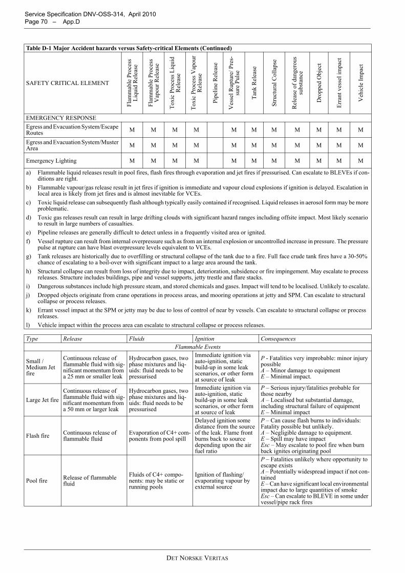
Service Specification DNV-OSS-314, April 2010 Page 70 – App.D
EMERGENCY RESPONSEEgress and Evacuation System/Escape Routes M M M M M M M M M M M
Egress and Evacuation System/Muster Area M M M M M M M M M M M
Emergency Lighting M M M M M M M M M M M
a) Flammable liquid releases result in pool fires, flash fires through evaporation and jet fires if pressurised. Can escalate to BLEVEs if con-ditions are right.
b) Flammable vapour/gas release result in jet fires if ignition is immediate and vapour cloud explosions if ignition is delayed. Escalation in local area is likely from jet fires and is almost inevitable for VCEs.
c) Toxic liquid release can subsequently flash although typically easily contained if recognised. Liquid releases in aerosol form may be more problematic.
d) Toxic gas releases result can result in large drifting clouds with significant hazard ranges including offsite impact. Most likely scenario to result in large numbers of casualties.
e) Pipeline releases are generally difficult to detect unless in a frequently visited area or ignited.f) Vessel rupture can result from internal overpressure such as from an internal explosion or uncontrolled increase in pressure. The pressure
pulse at rupture can have blast overpressure levels equivalent to VCEs.g) Tank releases are historically due to overfilling or structural collapse of the tank due to a fire. Full face crude tank fires have a 30-50%
chance of escalating to a boil-over with significant impact to a large area around the tank.h) Structural collapse can result from loss of integrity due to impact, deterioration, subsidence or fire impingement. May escalate to process
releases. Structure includes buildings, pipe and vessel supports, jetty trestle and flare stacks.i) Dangerous substances include high pressure steam, and stored chemicals and gases. Impact will tend to be localised. Unlikely to escalate.j) Dropped objects originate from crane operations in process areas, and mooring operations at jetty and SPM. Can escalate to structural
collapse or process releases.k) Errant vessel impact at the SPM or jetty may be due to loss of control of near by vessels. Can escalate to structural collapse or process
releases.l) Vehicle impact within the process area can escalate to structural collapse or process releases.
Type Release Fluids Ignition ConsequencesFlammable Events
Small /Medium Jet fire
Continuous release of flammable fluid with sig-nificant momentum from a 25 mm or smaller leak
Hydrocarbon gases, two phase mixtures and liq-uids: fluid needs to be pressurised
Immediate ignition via auto-ignition, static build-up in some leak scenarios, or other form at source of leak
P - Fatalities very improbable: minor injury possibleA – Minor damage to equipmentE – Minimal impact.
Large Jet fireContinuous release of flammable fluid with sig-nificant momentum from a 50 mm or larger leak
Hydrocarbon gases, two phase mixtures and liq-uids: fluid needs to be pressurised
Immediate ignition via auto-ignition, static build-up in some leak scenarios, or other form at source of leak
P – Serious injury/fatalities probable for those nearbyA – Localised but substantial damage, including structural failure of equipmentE – Minimal impact
Flash fire Continuous release of flammable fluid
Evaporation of C4+ com-ponents from pool spill
Delayed ignition some distance from the source of the leak. Flame front burns back to source depending upon the air fuel ratio
P – Can cause flash burns to individuals: Fatality possible but unlikely.A – Negligible damage to equipment.E – Spill may have impactEsc – May escalate to pool fire when burn back ignites originating pool
Pool fire Release of flammable fluid
Fluids of C4+ compo-nents: may be static or running pools
Ignition of flashing/evaporating vapour by external source
P – Fatalities unlikely where opportunity to escape existsA – Potentially widespread impact if not con-tainedE – Can have significant local environmental impact due to large quantities of smokeEsc – Can escalate to BLEVE in some under vessel/pipe rack fires
Table D-1 Major Accident hazards versus Safety-critical Elements (Continued)
SAFETY CRITICAL ELEMENT
Flam
mab
le P
roce
ss
Liqu
id R
elea
se
Flam
mab
le P
roce
ss
Vap
our R
elea
se
Toxi
c Pr
oces
s Liq
uid
Rel
ease
Toxi
c Pr
oces
s Vap
our
Rel
ease
Pipe
line
Rel
ease
Ves
sel R
uptu
re/ P
res-
sure
Pul
se
Tank
Rel
ease
Stru
ctur
al C
olla
pse
Rel
ease
of d
ange
rous
su
bsta
nce
Dro
pped
Obj
ect
Erra
nt v
esse
l im
pact
Veh
icle
Impa
ct
DET NORSKE VERITAS
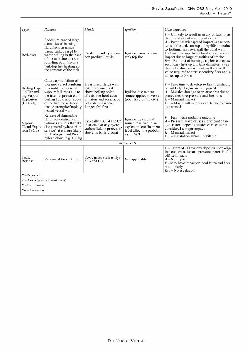
Service Specification DNV-OSS-314, April 2010 App.D – Page 71
Boil-over
Sudden release of large quantities of burning fluid from an atmos-pheric tank, caused by water boiling in the base of the tank due to a sur-rounding pool fire or a tank-top fire heating up the contents of the tank
Crude oil and hydrocar-bon product liquids
Ignition from existing tank top fire
P – Unlikely to result in injury or fatality as there is plenty of warning of eventA – Potential widespread impact as the con-tents of the tank can expand by 400 times due to frothing: may overspill the bund wallE - Can have significant local environmental impact due to large quantities of smokeEsc - Rain-out of burning droplets can cause secondary fires up to 5 tank diameters away: thermal radiation can peak well above the value required to start secondary fires at dis-tances up to 200m
Boiling Liq-uid Expand-ing Vapour Explosion (BLEVE)
Catastrophic failure of pressure vessel resulting in a sudden release of vapour: failure is due to the internal pressure of boiling liquid and vapour exceeding the reduced tensile strength of rapidly heated vessel wall
Pressurised fluids with C4+ components if above boiling point: affects overhead accu-mulators and vessels, but not columns where flanges fail first
Ignition due to heat source applied to vessel (pool fire, jet fire etc.)
P – Take time to develop so fatalities should be unlikely if signs are recognisedA – Massive damage over large area due to projectiles, overpressure and fire ballsE – Minimal impactEsc – May result in other events due to dam-age caused
Vapour Cloud Explo-sion (VCE)
Release of flammable fluid: very unlikely if volumes are less that 10t (for general hydrocarbon service): it is more likely for Hydrogen and Pro-pylene cloud, e.g. 100 kg
Typically C3, C4 and C5 in storage or any hydro-carbon fluid in process if above its boiling point
Ignition by external source resulting in an explosion: confinement level affect the probabil-ity of VCE
P – Fatalities a probable outcomeA – Pressure wave causes significant dam-age. Extent depends on size of release but considered a major impact.E – Minimal impactEsc – Escalation almost inevitable
Toxic Events
Toxic Release Release of toxic fluids Toxic gases such as H2S,
SO2 and CO Not applicable
P – Extent of CO toxicity depends upon orig-inal concentration and pressure: potential for offsite impactsA – No impactE – May have impact on local fauna and flora but unlikelyEsc – No escalation
P = PersonnelA = Assets (plant and equipment)E = EnvironmentEsc = Escalation
Type Release Fluids Ignition Consequences
DET NORSKE VERITAS
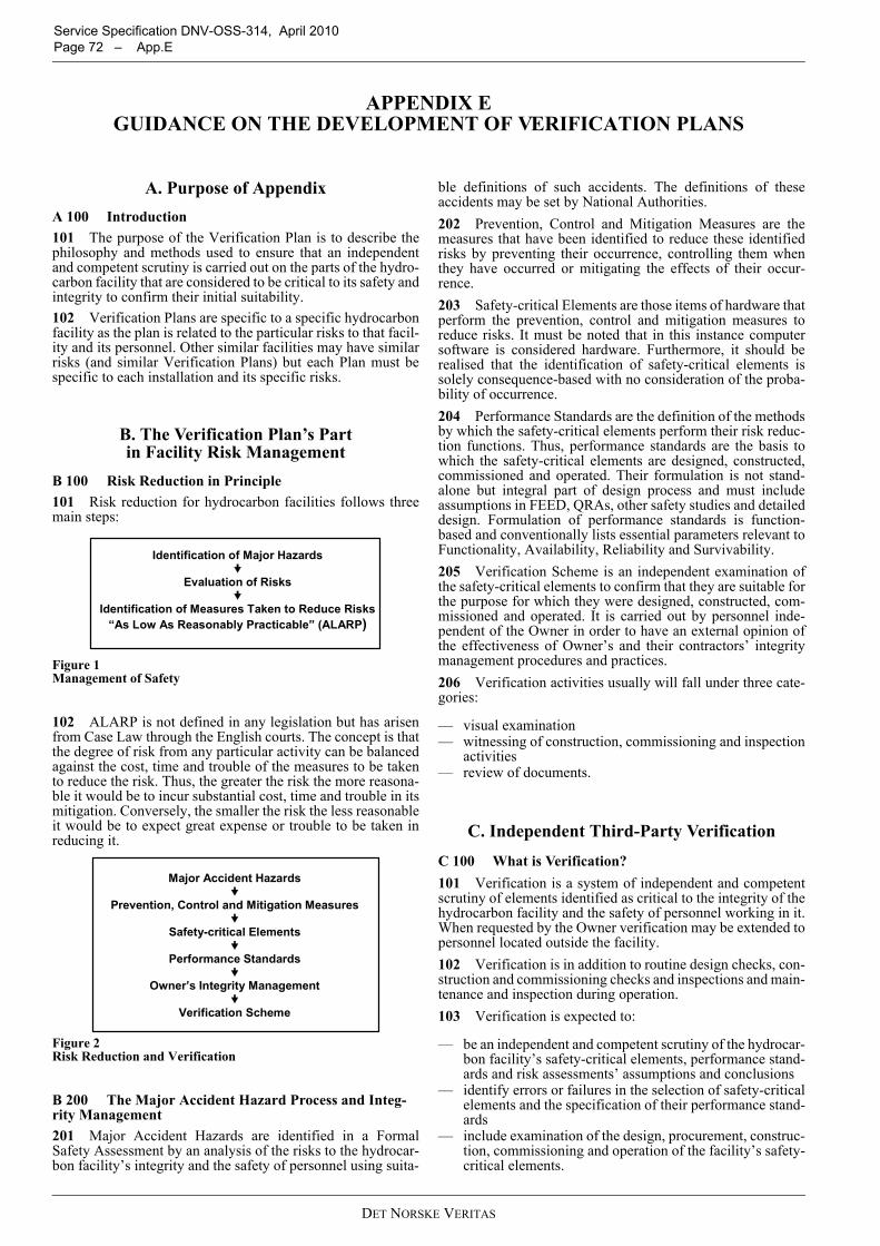
Service Specification DNV-OSS-314, April 2010 Page 72 – App.E
APPENDIX E GUIDANCE ON THE DEVELOPMENT OF VERIFICATION PLANS
A. Purpose of AppendixA 100 Introduction101 The purpose of the Verification Plan is to describe thephilosophy and methods used to ensure that an independentand competent scrutiny is carried out on the parts of the hydro-carbon facility that are considered to be critical to its safety andintegrity to confirm their initial suitability.102 Verification Plans are specific to a specific hydrocarbonfacility as the plan is related to the particular risks to that facil-ity and its personnel. Other similar facilities may have similarrisks (and similar Verification Plans) but each Plan must bespecific to each installation and its specific risks.
B. The Verification Plan’s Part in Facility Risk Management
B 100 Risk Reduction in Principle101 Risk reduction for hydrocarbon facilities follows threemain steps:
Figure 1 Management of Safety
102 ALARP is not defined in any legislation but has arisenfrom Case Law through the English courts. The concept is thatthe degree of risk from any particular activity can be balancedagainst the cost, time and trouble of the measures to be takento reduce the risk. Thus, the greater the risk the more reasona-ble it would be to incur substantial cost, time and trouble in itsmitigation. Conversely, the smaller the risk the less reasonableit would be to expect great expense or trouble to be taken inreducing it.
Figure 2 Risk Reduction and Verification
B 200 The Major Accident Hazard Process and Integ-rity Management201 Major Accident Hazards are identified in a FormalSafety Assessment by an analysis of the risks to the hydrocar-bon facility’s integrity and the safety of personnel using suita-
ble definitions of such accidents. The definitions of theseaccidents may be set by National Authorities.202 Prevention, Control and Mitigation Measures are themeasures that have been identified to reduce these identifiedrisks by preventing their occurrence, controlling them whenthey have occurred or mitigating the effects of their occur-rence.203 Safety-critical Elements are those items of hardware thatperform the prevention, control and mitigation measures toreduce risks. It must be noted that in this instance computersoftware is considered hardware. Furthermore, it should berealised that the identification of safety-critical elements issolely consequence-based with no consideration of the proba-bility of occurrence.204 Performance Standards are the definition of the methodsby which the safety-critical elements perform their risk reduc-tion functions. Thus, performance standards are the basis towhich the safety-critical elements are designed, constructed,commissioned and operated. Their formulation is not stand-alone but integral part of design process and must includeassumptions in FEED, QRAs, other safety studies and detaileddesign. Formulation of performance standards is function-based and conventionally lists essential parameters relevant toFunctionality, Availability, Reliability and Survivability.205 Verification Scheme is an independent examination ofthe safety-critical elements to confirm that they are suitable forthe purpose for which they were designed, constructed, com-missioned and operated. It is carried out by personnel inde-pendent of the Owner in order to have an external opinion ofthe effectiveness of Owner’s and their contractors’ integritymanagement procedures and practices.206 Verification activities usually will fall under three cate-gories:
— visual examination— witnessing of construction, commissioning and inspection
activities— review of documents.
C. Independent Third-Party VerificationC 100 What is Verification?101 Verification is a system of independent and competentscrutiny of elements identified as critical to the integrity of thehydrocarbon facility and the safety of personnel working in it.When requested by the Owner verification may be extended topersonnel located outside the facility.102 Verification is in addition to routine design checks, con-struction and commissioning checks and inspections and main-tenance and inspection during operation.103 Verification is expected to:
— be an independent and competent scrutiny of the hydrocar-bon facility’s safety-critical elements, performance stand-ards and risk assessments’ assumptions and conclusions
— identify errors or failures in the selection of safety-criticalelements and the specification of their performance stand-ards
— include examination of the design, procurement, construc-tion, commissioning and operation of the facility’s safety-critical elements.
Identification of Major Hazards
Evaluation of Risks
Identification of Measures Taken to Reduce Risks“As Low As Reasonably Practicable” (ALARP)
Major Accident Hazards
Prevention, Control and Mitigation Measures
Safety-critical Elements
Performance Standards
Owner’s Integrity Management
Verification Scheme
DET NORSKE VERITAS
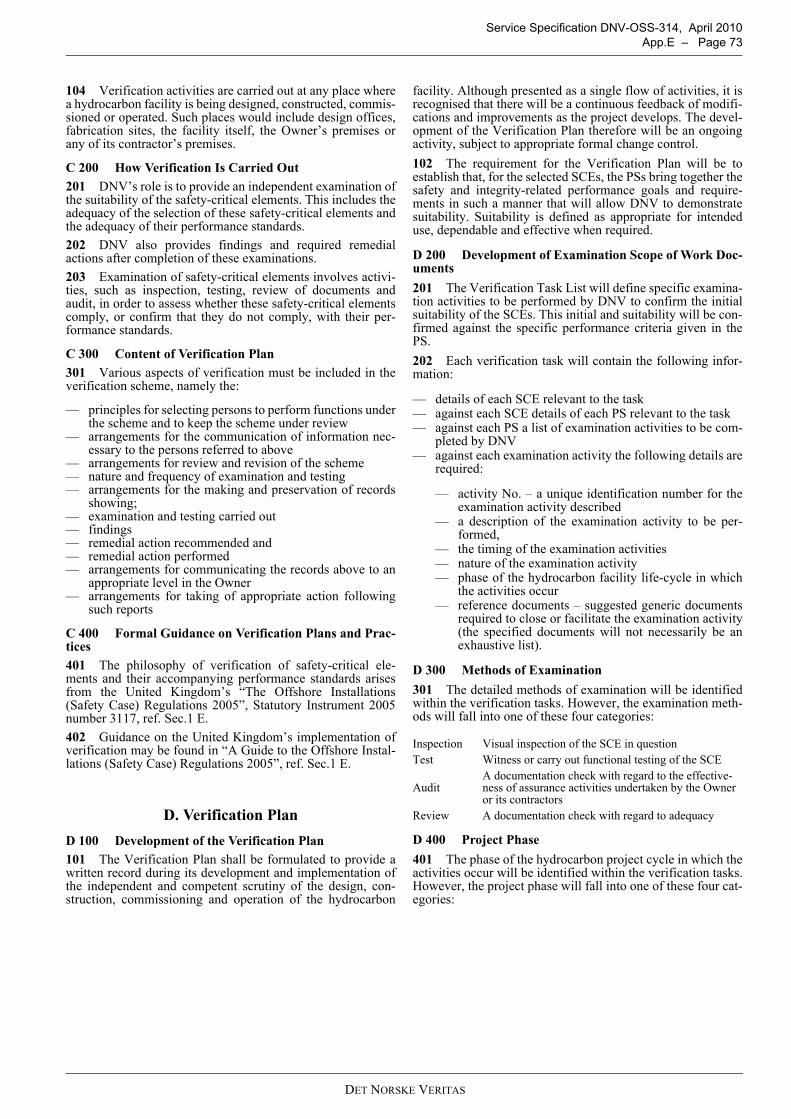
Service Specification DNV-OSS-314, April 2010 App.E – Page 73
104 Verification activities are carried out at any place wherea hydrocarbon facility is being designed, constructed, commis-sioned or operated. Such places would include design offices,fabrication sites, the facility itself, the Owner’s premises orany of its contractor’s premises.
C 200 How Verification Is Carried Out201 DNV’s role is to provide an independent examination ofthe suitability of the safety-critical elements. This includes theadequacy of the selection of these safety-critical elements andthe adequacy of their performance standards.202 DNV also provides findings and required remedialactions after completion of these examinations.203 Examination of safety-critical elements involves activi-ties, such as inspection, testing, review of documents andaudit, in order to assess whether these safety-critical elementscomply, or confirm that they do not comply, with their per-formance standards.
C 300 Content of Verification Plan301 Various aspects of verification must be included in theverification scheme, namely the:
— principles for selecting persons to perform functions underthe scheme and to keep the scheme under review
— arrangements for the communication of information nec-essary to the persons referred to above
— arrangements for review and revision of the scheme— nature and frequency of examination and testing— arrangements for the making and preservation of records
showing;— examination and testing carried out— findings— remedial action recommended and— remedial action performed— arrangements for communicating the records above to an
appropriate level in the Owner— arrangements for taking of appropriate action following
such reports
C 400 Formal Guidance on Verification Plans and Prac-tices401 The philosophy of verification of safety-critical ele-ments and their accompanying performance standards arisesfrom the United Kingdom’s “The Offshore Installations(Safety Case) Regulations 2005”, Statutory Instrument 2005number 3117, ref. Sec.1 E.402 Guidance on the United Kingdom’s implementation ofverification may be found in “A Guide to the Offshore Instal-lations (Safety Case) Regulations 2005”, ref. Sec.1 E.
D. Verification PlanD 100 Development of the Verification Plan101 The Verification Plan shall be formulated to provide awritten record during its development and implementation ofthe independent and competent scrutiny of the design, con-struction, commissioning and operation of the hydrocarbon
facility. Although presented as a single flow of activities, it isrecognised that there will be a continuous feedback of modifi-cations and improvements as the project develops. The devel-opment of the Verification Plan therefore will be an ongoingactivity, subject to appropriate formal change control.102 The requirement for the Verification Plan will be toestablish that, for the selected SCEs, the PSs bring together thesafety and integrity-related performance goals and require-ments in such a manner that will allow DNV to demonstratesuitability. Suitability is defined as appropriate for intendeduse, dependable and effective when required.
D 200 Development of Examination Scope of Work Doc-uments201 The Verification Task List will define specific examina-tion activities to be performed by DNV to confirm the initialsuitability of the SCEs. This initial and suitability will be con-firmed against the specific performance criteria given in thePS.202 Each verification task will contain the following infor-mation:
— details of each SCE relevant to the task— against each SCE details of each PS relevant to the task— against each PS a list of examination activities to be com-
pleted by DNV— against each examination activity the following details are
required:
— activity No. – a unique identification number for theexamination activity described
— a description of the examination activity to be per-formed,
— the timing of the examination activities— nature of the examination activity— phase of the hydrocarbon facility life-cycle in which
the activities occur— reference documents – suggested generic documents
required to close or facilitate the examination activity(the specified documents will not necessarily be anexhaustive list).
D 300 Methods of Examination301 The detailed methods of examination will be identifiedwithin the verification tasks. However, the examination meth-ods will fall into one of these four categories:
D 400 Project Phase401 The phase of the hydrocarbon project cycle in which theactivities occur will be identified within the verification tasks.However, the project phase will fall into one of these four cat-egories:
Inspection Visual inspection of the SCE in questionTest Witness or carry out functional testing of the SCE
AuditA documentation check with regard to the effective-ness of assurance activities undertaken by the Owner or its contractors
Review A documentation check with regard to adequacy
DET NORSKE VERITAS
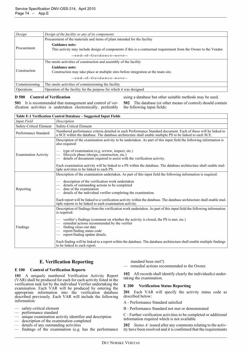
Service Specification DNV-OSS-314, April 2010 Page 74 – App.E
D 500 Control of Verification501 It is recommended that management and control of ver-ification activities is undertaken electronically, preferably
using a database but other suitable methods may be used.502 The database (or other means of control) should containthe following input fields:
E. Verification ReportingE 100 Control of Verification Reports101 A uniquely numbered Verification Activity Report(VAR) shall be produced for each for each activity listed in theverification task list by the individual Verifier undertaking theexamination. Each VAR will be produced by entering theappropriate information into the verification databasedescribed previously. Each VAR will include the followinginformation:
— safety-critical element— performance standard— unique examination activity identifier and description— description of the examination completed— details of any outstanding activities— findings of the examination (e.g. has the performance
standard been met?)— remedial actions recommended to the Owner.
102 All records shall identify clearly the individual(s) under-taking the examination.
E 200 Verification Status Reporting201 Each VAR will specify the activity status code asdescribed below:A - Performance Standard satisfiedB - Performance Standard not met or demonstratedC - Further verification activities to be completed or additionalinformation required which is not available202 Status A: issued after any comments relating to the activ-ity have been resolved and it is confirmed that the requirements
Design Design of the facility or any of its components
Procurement
Procurement of the materials and items of plant intended for the facilityGuidance note:This activity may include design of components if this is a contractual requirement from the Owner to the Vendor.
---e-n-d---of---G-u-i-d-a-n-c-e---n-o-t-e---
Construction
The onsite activities of construction and assembly of the facilityGuidance note:Construction may take place at multiple sites before integration at the main site.
---e-n-d---of---G-u-i-d-a-n-c-e---n-o-t-e---
Commissioning The onsite activities of commissioning the facilityOperations Operation of the facility for the purpose for which it was designed
Table E-1 Verification Control Database – Suggested Input FieldsInput Field DescriptionSafety-Critical Element Safety-Critical Element
Performance Standard Numbered performance criteria detailed in each Performance Standard document. Each of these will be linked to a SCE within the database. The database architecture shall enable multiple PS to be linked to each SCE.
Examination Activity
Description of the examination activity to be undertaken. As part of this input field the following information is also required:
— type of examination (e.g. review, inspect, etc.)— lifecycle phase (design, construction, etc.)— details of documents required to assist with the verification activity.
Each examination activity will be linked to a PS within the database. The database architecture shall enable mul-tiple activities to be linked to each PS.
Reporting
Description of the examination undertaken. As part of this input field the following information is required:
— description of the verification work undertaken— details of outstanding actions to be completed— date of the examination— details of the individual verifier completing the examination.
Each report will be linked to a verification activity within the database. The database architecture shall enable mul-tiple reports to be linked to each examination activity.
Findings
Description of findings from the verification work undertaken. As part of this input field the following information is required:
— verifier’s findings (comment on whether the activity is closed, the PS is met, etc.)— remedial actions recommended by the verifier— finding close-out date— report/finding status code— report/finding update details.
Each finding will be linked to a report within the database. The database architecture shall enable multiple findings to be linked to each report.
DET NORSKE VERITAS
Service Specification DNV-OSS-314, April 2010 App.E – Page 75
of the relevant Performance Standard have been met.203 Status B: issued after it is agreed with the Owner thatoutstanding comments cannot be resolved and that DNV can-not confirm that the requirements of the relevant PerformanceStandard have been met, or can confirm that the requirementshave not been met.
Guidance note:Where VAR Status B is issued by DNV, it is up to the owner tojustify to himself, and where necessary to the National Authori-ties, his basis for acceptance of the deviation from his previouslystated requirements.DNV’s final report will simply state that the VAR has beenissued at Status B and give the reasons for this.
---e-n-d---of---G-u-i-d-a-n-c-e---n-o-t-e---
204 Status C: not normally issued but the status recorded forprogress reporting, if required by the Owner.
F. Review and Revision of the Verification Plan
F 100 Continuous Review of the Plan101 The Verification Plan will remain live for the lifetime ofthe design, construction and commissioning of the hydrocar-bon facility. It is essential that there is a continuous feedbackof modifications and improvements as the project develops.The development of the Verification Plan therefore will be anongoing activity, subject to appropriate formal change control.
102 The Owner should ensure that all persons completingactivities relevant to the design, construction and commission-ing of the hydrocarbon facility are given the opportunity tocomment on the adequacy and possible improvement of theVerification Plan.
F 200 Events Initiating Revisions201 The Verification Plan may require changes that are trig-gered by events such as:
— major design changes during the design, construction oroperations phase
— Verification Plan is incorrect, deficient or requiresimproving
— change of record of SCEs (e.g. revised methodology foridentifying SCEs)
— change of Performance Standards (e.g. current PS inap-propriate, or due to technical advances)
— inability to confirm that SCE meets the requirements of itsPS
— major revision to supporting safety documentation (QRA,FERA, etc.)
— damage or incidents— change in record-keeping systems— change in responsibilities/accountabilities— change in reporting requirements.
202 When one or more of the above occurs, the Owner shallreview, and where deemed necessary update, the Plan. Thesereviews will be conducted in consultation with DNV, togetherwith any contractor’s personnel as appropriate.
DET NORSKE VERITAS

Service Specification DNV-OSS-314, April 2010 Page 76 – App.E
DET NORSKE VERITAS