Disabled Refuge EVC - Folknoll 7700-000 SM5... · Disabled Refuge EVC System Manual Doc RA7760.00...
74
Folknoll Disabled Refuge EVC RA7760.00 System Manual DR 7700-000 SM5 V1.03 25/08/2010 Disabled Refuge EVC System Manual System Manual Disabled Refuge EVC
Transcript of Disabled Refuge EVC - Folknoll 7700-000 SM5... · Disabled Refuge EVC System Manual Doc RA7760.00...

Folknoll
Disabled Refuge EVC
RA7760.00 System Manual
DR 7700-000 SM5 V1.03 25/08/2010 Disabled Refuge EVC System Manual
System Manual
Disabled Refuge EVC
Disabled Refuge EVC Page | i System Manual V1.03
Disabled Refuge EVC System Manual Doc RA7760.00 V1.03 25/08/2010, E&OE-©2010 Folknoll, all rights reserved
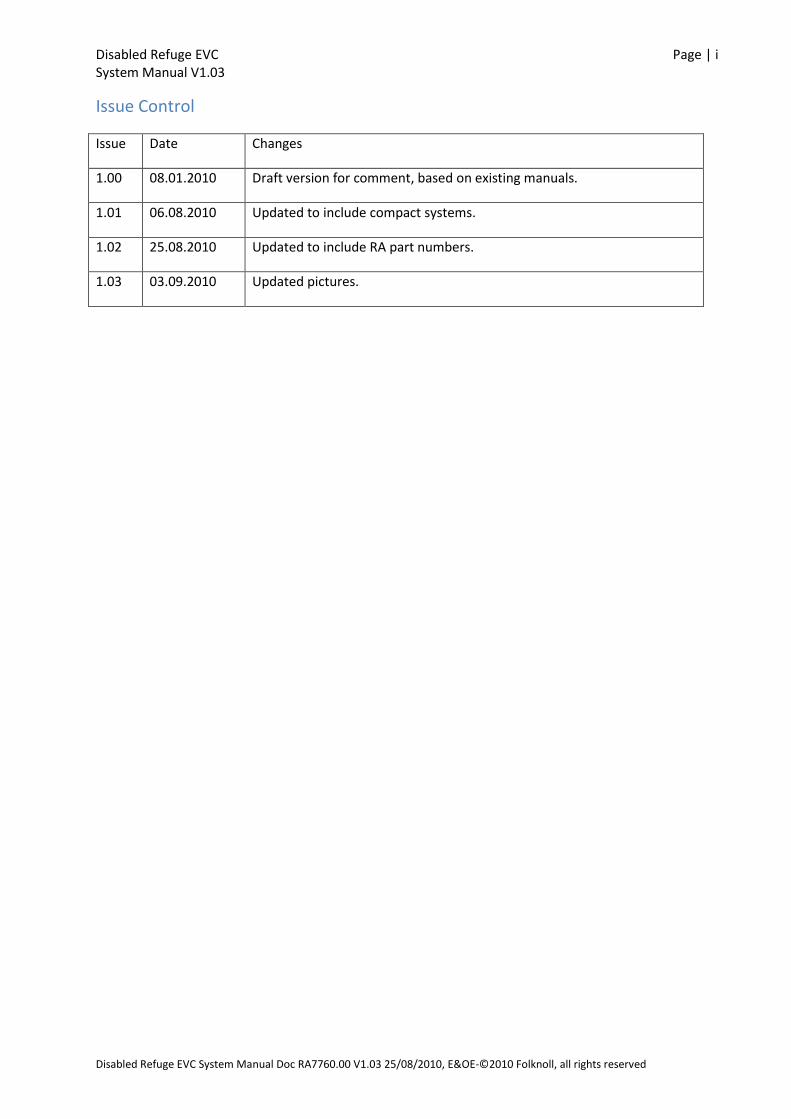
Issue Control
Issue Date Changes
1.00 08.01.2010 Draft version for comment, based on existing manuals.
1.01 06.08.2010 Updated to include compact systems.
1.02 25.08.2010 Updated to include RA part numbers.
1.03 03.09.2010 Updated pictures.

Disabled Refuge EVC Page | ii System Manual V1.03
Disabled Refuge EVC System Manual Doc RA7760.00 V1.03 25/08/2010 E&OE-©2010 Folknoll, all rights reserved
Contents
1 INTRODUCTION ................................................................................................................................. 1
1.1 WHAT IS A DISABLED REFUGE EVC SYSTEM 1
1.2 FOLKNOLL DISABLED REFUGE SYSTEMS 1
1.2.1 Cabling 1 1.2.2 Compact Systems 1 1.2.3 Standard Systems 1 1.2.4 Outstations 2 1.2.5 Master Stations 2 1.2.6 Keyed Enable Switch 2 1.2.7 Remote Enable 2 1.2.8 Single Monitored Battery Backed PSU 2 1.2.9 Audio Path Fault Monitoring and Reporting 2 1.3 DESIGNED FOR LIFE 2
1.4 COMPLETE SOLUTIONS 2
1.5 CUSTOM UNITS 3
1.6 CONTACT US 3
2 COMPACT DISABLED REFUGE EVC SYSTEMS .................................................................................... 4
2.1 COMPACT SYSTEM FEATURES 4
2.2 COMPACT SYSTEM OUTSTATION 5
2.3 COMPACT SYSTEM MASTER STATIONS 5
2.4 COMPACT SYSTEM FAULT MONITORING 6
2.4.1 Compact System Audio Path Monitoring and Reporting 6 2.5 COMPACT SYSTEM BATTERY BACKED PSU 7
2.6 COMPACT SYSTEM CABLING 7
2.6.1 Compact System Cabling layout 7 2.6.2 Compact System Cabling Rules 7 2.6.3 Compact System Cable Connections 8
3 STANDARD DISABLED REFUGE EVC SYSTEMS ................................................................................... 9
3.1 STANDARD SYSTEM FEATURES 9
3.2 STANDARD SYSTEM OUTSTATIONS 10
3.3 STANDARD SYSTEM MASTER STATIONS 10
3.4 STANDARD SYSTEM CONTROLLER 12
3.5 STANDARD SYSTEM FAULT MONITORING 13
3.5.1 Standard System Audio Path Monitoring and Reporting 13 3.6 STANDARD SYSTEM BATTERY BACKED PSU 13
3.7 STANDARD SYSTEM CABLING 14
3.7.1 Standard System Cabling layout 14 3.7.2 Standard System Cabling Rules 14 3.7.3 Standard System Cable Connections 14
4 INSTALLATION ................................................................................................................................. 16
5 COMMISSIONING ............................................................................................................................ 17
5.1 SYSTEM CONTROLLER ADDRESSING (STANDARD SYSTEM ONLY) 17
5.2 POWER FAULT MONITORING 17
5.3 OUTSTATION CONFIGURATION 18
5.4 ENABLE THE MASTER STATION KEYBOARD 18
5.5 INITIAL POWER UP 18
5.6 VOLUME ADJUSTMENT 19

Disabled Refuge EVC Page | iii System Manual V1.03
Disabled Refuge EVC System Manual Doc RA7760.00 V1.03 25/08/2010 E&OE-©2010 Folknoll, all rights reserved
5.7 AUDIO PATH TESTS (MICROPHONE AND SPEAKERTESTS) 19
6 OPERATION ..................................................................................................................................... 20
6.1 ENABLING THE MASTER STATION 20
6.2 ACCEPTING CALLS FROM OUTSTATIONS 20
6.3 MAKING CALLS TO OUTSTATIONS 21
6.4 ALL CALLS 21
6.5 FAULTS 22
6.6 MANUAL SYSTEM TEST (COMPACT SYSTEMS ONLY) 22
7 SYSTEM FAULTS............................................................................................................................... 23
7.1 SUMMARY OF SYSTEM FAULT INDICATIONS 23
7.2 MAINS POWER FAIL 24
7.3 SYSTEM POWERED WITH MASTER STATION DISABLED 24
7.4 AUDIO PATH FAULT 24
7.5 OUTSTATION CABLE DISCONNECTED 25
8 ROUTINE MAINTENANCE AND TESTING ......................................................................................... 26
8.1 ROUTINE MAINTENANCE 26
8.1.1 Standby Batteries 26 8.2 VISUAL INSPECTION 26
8.2.1 Outstations 26 8.2.2 Master Station 26 8.2.3 Control Equipment (Standard System Only) 27 8.3 FUNCTIONAL TESTING 27
8.3.1 User Call Check 27 8.3.2 Operator Call Check 27 8.3.3 All Call Check 27 8.3.4 Standby Operation Test 28 8.3.5 Standby Time Test 28 8.3.6 Standby Battery Charging Voltage Test 28 8.3.7 Audio Path Test 28 8.3.8 Automatic Audio Path Testing 29 9 DISABLED REFUGE EVC COMPONENTS ........................................................................................... 30
9.1 EXTERNAL OUTSTATION (P/N RA7700.60) 30
9.1.1 Features 30 9.1.2 Description 30 9.1.3 Parts 31 9.1.4 Specifications 31 9.1.5 Connections 31 9.2 INTERNAL OUTSTATION (P/N RA7700.30 AND RA7700.35) 32
9.2.1 Features 32 9.2.2 Description 32 9.2.3 Parts 32 9.2.4 Specifications 33 9.2.5 Connections 33 9.3 COMPACT SYSTEM 5 WAY MASTER STATION (P/N RA7805.01) 34
9.3.1 Features 34 9.3.2 Description 34 9.3.3 Parts 35 9.3.4 Specifications 35 9.3.5 Connections 36 9.4 COMPACT SYSTEM 10 WAY MASTER STATION (P/N RA7810.01) 37
9.4.1 Features 37

Disabled Refuge EVC Page | iv System Manual V1.03
Disabled Refuge EVC System Manual Doc RA7760.00 V1.03 25/08/2010 E&OE-©2010 Folknoll, all rights reserved
9.4.2 Description 37 9.4.3 Parts 38 9.4.4 Specifications 38 9.4.5 Connections 39 9.5 STANDARD SYSTEM 5 WAY MASTER STATION (P/N RA7705.01 RA7705.05) 40
9.5.1 Features 40 9.5.2 Description 40 9.5.3 Parts 41 9.5.4 Specifications 41 9.5.5 Connections 43 9.6 STANDARD SYSTEM 10 WAY MASTER STATION (P/N RA7710.01 RA7710.05) 44
9.6.1 Features 44 9.6.2 Description 44 9.6.3 Parts 45 9.6.4 Specifications 45 9.6.5 Connections 47 9.7 STANDARD SYSTEM 15-WAY MASTER STATION (P/N RA7715.01 RA7715.05) 48
9.7.1 Features 48 9.7.2 Description 48 9.7.3 Parts 49 9.7.4 Specifications 50 9.7.5 Connections 52 9.8 STANDARD SYSTEM 20-WAY MASTER STATION (P/N RA7720.01 RA7720.05) 53
9.8.1 Features 53 9.8.2 Description 53 9.8.3 Parts 54 9.8.4 Specifications 55 9.8.5 Connections 57 9.9 STANDARD SYSTEM CONTROLLER (P/N RA7700.02) 58
9.9.1 Features 58 9.9.2 Description 58 9.9.3 Parts 59 9.9.4 Specifications 59 9.9.5 Connections 59 9.10 STANDARD SYSTEM BATTERY BACKED PSU (P/N RA7750.02, RA7750.04) 61
9.10.1 Features 61 9.10.2 Description 61 9.10.3 Indicators 62 9.10.4 Parts 62 9.10.5 Specifications 62 9.10.6 Connections 62
10 APPENDIX A FIRETUFDATA .............................................................................................................. 64
11 APPENDIX B COMPACT SYSTEM MASTER STATION LABELS ........................................................... 65
12 USER NOTES .................................................................................................................................... 66
Disabled Refuge EVC Page | v System Manual V1.03
Disabled Refuge EVC System Manual Doc RA7760.00 V1.03 25/08/2010 E&OE-©2010 Folknoll, all rights reserved
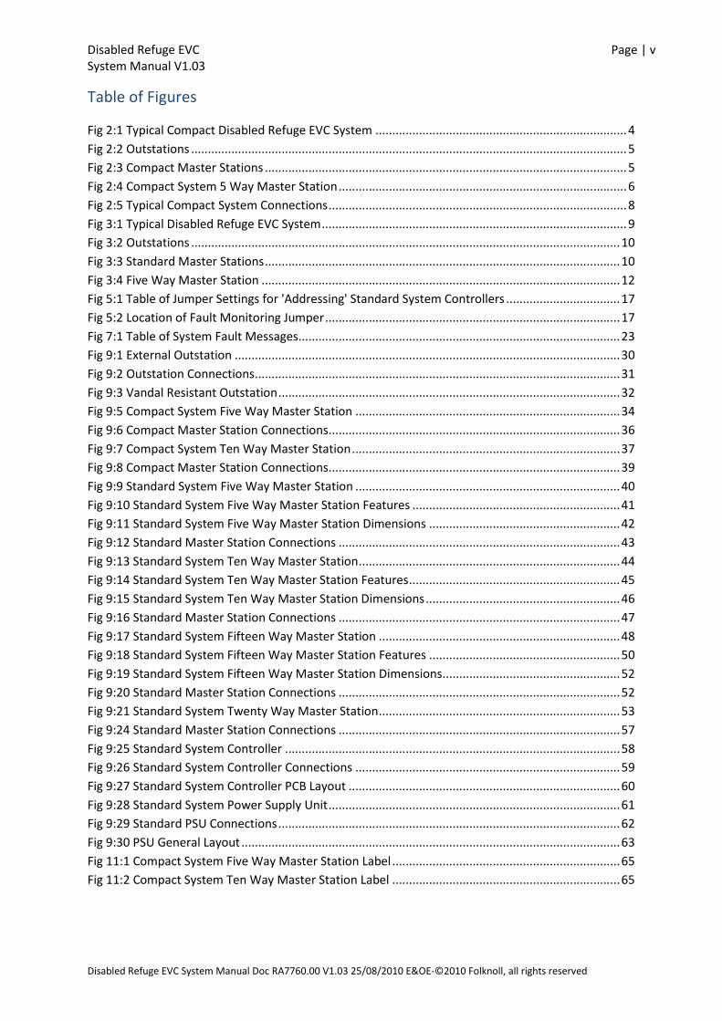
Table of Figures
Fig 2:1 Typical Compact Disabled Refuge EVC System ........................................................................... 4
Fig 2:2 Outstations .................................................................................................................................. 5
Fig 2:3 Compact Master Stations ............................................................................................................ 5
Fig 2:4 Compact System 5 Way Master Station ...................................................................................... 6
Fig 2:5 Typical Compact System Connections ......................................................................................... 8
Fig 3:1 Typical Disabled Refuge EVC System ........................................................................................... 9
Fig 3:2 Outstations ................................................................................................................................ 10
Fig 3:3 Standard Master Stations .......................................................................................................... 10
Fig 3:4 Five Way Master Station ........................................................................................................... 12
Fig 5:1 Table of Jumper Settings for 'Addressing' Standard System Controllers .................................. 17
Fig 5:2 Location of Fault Monitoring Jumper ........................................................................................ 17
Fig 7:1 Table of System Fault Messages................................................................................................ 23
Fig 9:1 External Outstation ................................................................................................................... 30
Fig 9:2 Outstation Connections ............................................................................................................. 31
Fig 9:3 Vandal Resistant Outstation ...................................................................................................... 32
Fig 9:5 Compact System Five Way Master Station ............................................................................... 34
Fig 9:6 Compact Master Station Connections ....................................................................................... 36
Fig 9:7 Compact System Ten Way Master Station ................................................................................ 37
Fig 9:8 Compact Master Station Connections ....................................................................................... 39
Fig 9:9 Standard System Five Way Master Station ............................................................................... 40
Fig 9:10 Standard System Five Way Master Station Features .............................................................. 41
Fig 9:11 Standard System Five Way Master Station Dimensions ......................................................... 42
Fig 9:12 Standard Master Station Connections .................................................................................... 43
Fig 9:13 Standard System Ten Way Master Station .............................................................................. 44
Fig 9:14 Standard System Ten Way Master Station Features ............................................................... 45
Fig 9:15 Standard System Ten Way Master Station Dimensions .......................................................... 46
Fig 9:16 Standard Master Station Connections .................................................................................... 47
Fig 9:17 Standard System Fifteen Way Master Station ........................................................................ 48
Fig 9:18 Standard System Fifteen Way Master Station Features ......................................................... 50
Fig 9:19 Standard System Fifteen Way Master Station Dimensions ..................................................... 52
Fig 9:20 Standard Master Station Connections .................................................................................... 52
Fig 9:21 Standard System Twenty Way Master Station ........................................................................ 53
Fig 9:24 Standard Master Station Connections .................................................................................... 57
Fig 9:25 Standard System Controller .................................................................................................... 58
Fig 9:26 Standard System Controller Connections ............................................................................... 59
Fig 9:27 Standard System Controller PCB Layout ................................................................................. 60
Fig 9:28 Standard System Power Supply Unit ....................................................................................... 61
Fig 9:29 Standard PSU Connections ...................................................................................................... 62
Fig 9:30 PSU General Layout ................................................................................................................. 63
Fig 11:1 Compact System Five Way Master Station Label .................................................................... 65
Fig 11:2 Compact System Ten Way Master Station Label .................................................................... 65
Disabled Refuge EVC Page | 1 System Manual V1.03
Disabled Refuge EVC System Manual Doc RA7760.00 V1.03 25/08/2010, E&OE-©2010 Folknoll, all rights reserved
1 INTRODUCTION This document is the System Manual for Folknoll compact and standard range of Disabled Refuge
EVC systems.
The Folknoll Disabled Refuge EVC series is a range of easy to install, easy to configure and easy to
operate equipment, designed to enable you and your clients to install BS5839-9 compliant vandal
resistant disabled refuge EVC systems.
1.1 WHAT IS A DISABLED REFUGE EVC SYSTEM
In the event of an emergency disabled people make their way to disabled refuge areas to wait for
rescue. The Disabled Refuge EVC system is used to contact the evacuation organiser to request
assistance. The evacuation organiser uses the Disabled Refuge EVC system to instruct, inform and
reassure people waiting in the disabled refuge areas.
1.2 FOLKNOLL DISABLED REFUGE SYSTEMS
Folknoll Disabled Refuge EVC systems comprise a number of outstations located in disabled refuge
areas, control equipment and a master station located in the control or operations area. A range of
options are available to construct a system suit your requirements. All Folknoll Disabled Refuge EVC
systems have a key enabled switch, integral fault monitoring, and can be powered from a battery
backed power supply providing at least 24 hours standby and 30 minutes operation in the event of a
power fail.
1.2.1 Cabling
At Folknoll all equipment is designed by experience engineers for ease of operation installation and
operation. In particular all Disabled Refuge EVC systems have taken into account the BS requirement
to use larger fire resistant cabling, providing cable termination within enclosures, allowing room for
larger glands and avoiding the need for additional junction boxes.
1.2.2 Compact Systems
For smaller systems, with 10 refuge areas or less, Folknoll offer their cost effective compact system.
Compact system installation costs are reduced without compromising functionality by building the
system controller and a battery backed PSU into the compact system master station. Outstations are
cabled directly to the compact system master station. The compact system master stations are the
same size and have similar build quality to standard fire alarm panels.
1.2.3 Standard Systems
For larger systems, requiring more facilities and options Folknoll offer their more flexible standard
system. Outstations are connected to daisy chained system controllers allowing more cabling
options. Up to four system controllers can be connected into the system allowing a larger number of
outstations. Standard system master stations are vandal resistant offering a more robust solution for
more exposed control areas.
Disabled Refuge EVC Page | 2 System Manual V1.03
Disabled Refuge EVC System Manual Doc RA7760.00 V1.03 25/08/2010 E&OE-©2010 Folknoll, all rights reserved
1.2.4 Outstations
Folknoll offer surface or flush mount vandal resistant and surface mount IP65 external outstations
for used with compact or standard Disabled Refuge EVC systems.
1.2.5 Master Stations
Folknoll offer a range of 2-off fire panel sized compact system master stations with integral system
controller and PSU for smaller systems, and 4-off vandal resistant standard system master stations
for larger systems.
1.2.6 Keyed Enable Switch
All compact and standard Folknoll Disabled Refuge EVC system master stations have a keyed enable
switch which can be used to prevent unauthorised access.
1.2.7 Remote Enable
All compact and standard Folknoll Disabled Refuge EVC systems have a remote enable input. This
allows a remote device such as a management system or fire alarm system to enable the master
station irrespective of the state of the keyed enable switch.
1.2.8 Single Monitored Battery Backed PSU
All Folknoll compact and standard Disabled Refuge EVC systems can be powered from a single
battery backed PSU. In the event of a mains failure the backup unit is capable of providing at least 24
hours standby and 30 minutes operation. The mains supply is monitored and supply failures are
reported by the master station.
1.2.9 Audio Path Fault Monitoring and Reporting
Compact and standard Folknoll Disabled Refuge EVC systems offer audio path monitoring and
reporting. Audio tones are sent to outstation speakers, received by outstation microphones and
compared. Any discrepancies caused for example by chewing gum covering the microphone hole are
reported by the master station.
Compact and manual audio path testing can be triggered by external timers or management
systems. Audio path test fail output(s) are available to activate external devices or warning
management systems.
Compact systems can have a manual test switch and internal timer.
1.3 DESIGNED FOR LIFE
As with all Folknoll products, the Disabled Refuge EVCsystems have been designed for easy
installation, simple configuration, straightforward operation, excellent testing facilities, low
maintenance and high reliability.
1.4 COMPLETE SOLUTIONS
Folknoll are happy to assist in specifying equipment, configuring systems and providing connection
diagrams.
Disabled Refuge EVC Page | 3 System Manual V1.03
Disabled Refuge EVC System Manual Doc RA7760.00 V1.03 25/08/2010 E&OE-©2010 Folknoll, all rights reserved
1.5 CUSTOM UNITS
Folknoll is a customer focused company. If you require special software features, custom made units
or larger systems, then please contact Folknoll to discuss your requirements.
1.6 CONTACT US
For further information about Folknoll Disabled Refuge EVC systems or any other Folknoll products
please contact us on +44 (0) 1763 234567, email us at [email protected], or visit our website at
www.folknoll.co.uk.
Disabled Refuge EVC Page | 4 System Manual V1.03
Disabled Refuge EVC System Manual Doc RA7760.00 V1.03 25/08/2010 E&OE-©2010 Folknoll, all rights reserved
2 COMPACT DISABLED REFUGE EVC SYSTEMS For smaller sites with 10 or less refuge areas, Folknoll offer their cost effective compact Disabled
Refuge EVC system, where vandal resistant master stations are not required.
Compact system installation costs are reduced without compromising functionality by building the
system controller and a battery backed PSU into the compact system master station. Terminals are
provided within all equipment for cable terminations and space is allowed for glanding of larger fire
resistant cable types to comply with BS requirements. The equipment count is reduced and cabling
simplified.
Compact system master stations are designed to match stand fire alarm size and quality and are
suitable for mounting in similar secure areas.
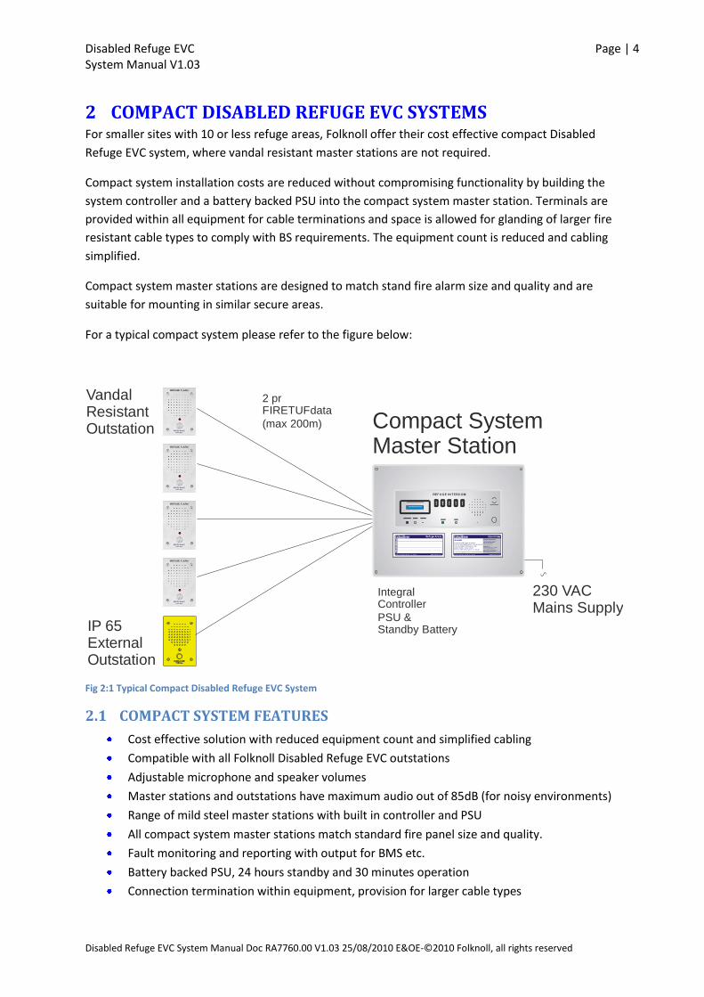
For a typical compact system please refer to the figure below:
Integral Controller
PSU &Standby Battery
Compact SystemMaster Station
VandalResistantOutstation
IP 65ExternalOutstation
230 VACMains Supply
2 prFIRETUFdata
(max 200m)
REFUGE INTERCOM
Fig 2:1 Typical Compact Disabled Refuge EVC System
2.1 COMPACT SYSTEM FEATURES
Cost effective solution with reduced equipment count and simplified cabling
Compatible with all Folknoll Disabled Refuge EVC outstations
Adjustable microphone and speaker volumes
Master stations and outstations have maximum audio out of 85dB (for noisy environments)
Range of mild steel master stations with built in controller and PSU
All compact system master stations match standard fire panel size and quality.
Fault monitoring and reporting with output for BMS etc.
Battery backed PSU, 24 hours standby and 30 minutes operation
Connection termination within equipment, provision for larger cable types

Disabled Refuge EVC Page | 5 System Manual V1.03
Disabled Refuge EVC System Manual Doc RA7760.00 V1.03 25/08/2010 E&OE-©2010 Folknoll, all rights reserved
2.2 COMPACT SYSTEM OUTSTATION
REFUGE ALARM
PRESS ONCE TO CALL
Fig 2:2 Outstations
Outstations are located in refuge areas and used by uses to communicate with evacuation
organisers.
Folknoll offer 2-off outstations, the bright yellow RA7700.60 IP65 external outstation and the vandal
resistant stainless steel RA7700.30 and RA7700.35 internal outstation.
Each outstation has an integral microphone and speaker, a large CALL button and a call progress
LED.
Microphone and speaker volume can be adjusted with a maximum output of 85dB for use in noisy
environments.
Please refer to section 9 Disabled Refuge EVC Components.
2.3 COMPACT SYSTEM MASTER STATIONS
TALK ALLACCEPT TEST FAULT
REFUGE INTERCOM
63 x 12mm Cutout
SYSTEM MONITOR 1 2 3 4 5
ENABLE
Fig 2:3 Compact Master Stations
Master stations are located in the control or operations area and used by the evacuation organizer
to communicate with all system users.
Compact system master stations comprise an operator control panel, a system controller and
battery backed PSU.
TALK ALLACCEPT TEST FAULT
REFUGE INTERCOM
63 x 12mm Cutout
SYSTEM MONITOR
6
1
7
2
8
3
9
4
10
5
ENABLE
Disabled Refuge EVC Page | 6 System Manual V1.03
Disabled Refuge EVC System Manual Doc RA7760.00 V1.03 25/08/2010 E&OE-©2010 Folknoll, all rights reserved
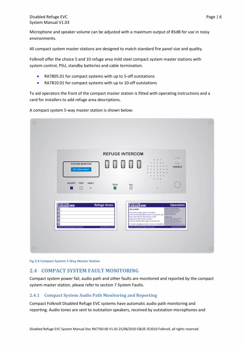
Microphone and speaker volume can be adjusted with a maximum output of 85dB for use in noisy
environments.
All compact system master stations are designed to match standard fire panel size and quality.
Folknoll offer the choice 5 and 10 refuge area mild steel compact system master stations with
system control, PSU, standby batteries and cable termination.
RA7805.01 for compact systems with up to 5-off outstations
RA7810.01 for compact systems with up to 10-off outstations
To aid operators the front of the compact master station is fitted with operating instructions and a
card for installers to add refuge area descriptions.
A compact system 5-way master station is shown below:
TALK ALLACCEPT TEST FAULT
REFUGE INTERCOM
63 x 12mm Cutout
SYSTEM MONITOR 1 2 3 4 5
ENABLE
Fig 2:4 Compact System 5 Way Master Station
2.4 COMPACT SYSTEM FAULT MONITORING
Compact system power fail, audio path and other faults are monitored and reported by the compact
system master station, please refer to section 7 System Faults.
2.4.1 Compact System Audio Path Monitoring and Reporting
Compact Folknoll Disabled Refuge EVC systems have automatic audio path monitoring and
reporting. Audio tones are sent to outstation speakers, received by outstation microphones and

Disabled Refuge EVC Page | 7 System Manual V1.03
Disabled Refuge EVC System Manual Doc RA7760.00 V1.03 25/08/2010 E&OE-©2010 Folknoll, all rights reserved
compared. Any discrepancies are reported by the compact master station, please refer to section 7
System Faults.
Compact system master stations have a manual TEST button and internal timer which may be
configured to trigger audio path testing.
Audio path testing may also be triggered by external devices such as a timer or management system.
Compact system audio path testing can also be triggered by applying a short to connector TBC on
the compact master station.
An audio path test fail output is available to activate an external indicator or to interface with an
external monitoring system.
Please refer to section 9.3 Compact System 5 Way Master Station (P/N RA7805.01) or section 9.4
Compact System 10 Way Master Station (P/N RA7810.01).
NOTE: During testing outstations will emit audio tones. Testing should be timed to minimise
inconvenience.
2.5 COMPACT SYSTEM BATTERY BACKED PSU
All Folknoll compact and standard Disabled Refuge EVC systems can be powered from a single
battery backed PSU. In the event of a mains failure the backup unit is capable of providing at least 24
hours standby and 30 minutes operation. The mains supply is monitored and supply failures are
reported by the master station.
The Compact system PSU is built into the compact system master station, please refer to section 9.3
Compact System 5 Way Master Station (P/N RA7805.01) and section 9.4 Compact System 10 Way
Master Station (P/N RA7810.01).
2.6 COMPACT SYSTEM CABLING
Outstations are star wired to the compact system master station, enabling simple cost effective
installation.
NOTE: all type cables should conform to the relevant British Standards, fire resistant cabling may
be required e.g. FIRETUFdata, please refer to section 10 APPENDIX A FIRETUFdata.
2.6.1 Compact System Cabling layout
Each outstation is connected by a shielded 2 pair cable to the master station.
The master station is connected to mains supply.
2.6.2 Compact System Cabling Rules
No termination resistors are required.
Assuming FIRETUFdata cable is used the maximum length of cable between each outstation
and the master station is 200m.

Disabled Refuge EVC Page | 8 System Manual V1.03
Disabled Refuge EVC System Manual Doc RA7760.00 V1.03 25/08/2010 E&OE-©2010 Folknoll, all rights reserved
2.6.3 Compact System Cable Connections
All connection is via terminal block located within the equipment, ‘knockouts’ have been provided
for cable entry. Folknoll’s design has allowed sufficient room for glands for larger fire resistant cable
types to comply with BS requirements.
Please refer to the drawing below:
LIV
E
EA
RT
H
NE
UT
RA
L
MAINS
SPK -
MIC +
MIC -
SCR
SPK +
SPK -
MIC +
MIC -
SCR
SPK +
OUTSTATION N
OUTSTATION 1
COMPACT MASTER STATION
SPK -
MIC +
MIC -
SPK +
SPK -
MIC +
MIC -
SPK +
CONTROL BOARD
PSU
Fig 2:5 Typical Compact System Connections
Disabled Refuge EVC Page | 9 System Manual V1.03
Disabled Refuge EVC System Manual Doc RA7760.00 V1.03 25/08/2010 E&OE-©2010 Folknoll, all rights reserved
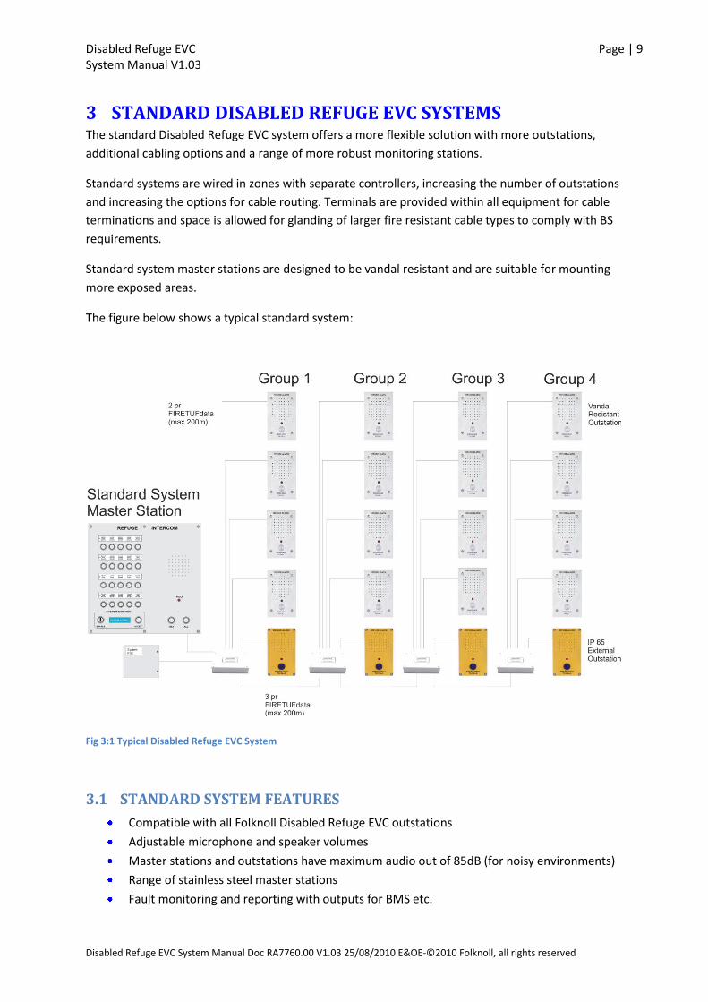
3 STANDARD DISABLED REFUGE EVC SYSTEMS The standard Disabled Refuge EVC system offers a more flexible solution with more outstations,
additional cabling options and a range of more robust monitoring stations.
Standard systems are wired in zones with separate controllers, increasing the number of outstations
and increasing the options for cable routing. Terminals are provided within all equipment for cable
terminations and space is allowed for glanding of larger fire resistant cable types to comply with BS
requirements.
Standard system master stations are designed to be vandal resistant and are suitable for mounting
more exposed areas.
The figure below shows a typical standard system:
Fig 3:1 Typical Disabled Refuge EVC System
3.1 STANDARD SYSTEM FEATURES
Compatible with all Folknoll Disabled Refuge EVC outstations
Adjustable microphone and speaker volumes
Master stations and outstations have maximum audio out of 85dB (for noisy environments)
Range of stainless steel master stations
Fault monitoring and reporting with outputs for BMS etc.

Disabled Refuge EVC Page | 10 System Manual V1.03
Disabled Refuge EVC System Manual Doc RA7760.00 V1.03 25/08/2010 E&OE-©2010 Folknoll, all rights reserved
Battery backed PSU, 24 hours standby and 30 minutes operation
Connection termination within equipment, provision for larger cable types
Separate system controllers and PSU; allows more outstations; allows more cabling options
3.2 STANDARD SYSTEM OUTSTATIONS
REFUGE ALARM
PRESS ONCE TO CALL
Fig 3:2 Outstations
Outstations are located in refuge areas and used by uses to communicate with evacuation
organisers.
Folknoll offer 2-off outstations, the bright yellow RA7700.60 IP65 external outstation and the vandal
resistant stainless steel RA7700.30 and RA7700.35 internal outstation.
Each outstation has an integral microphone and speaker, a large CALL button and a call progress
LED.
Microphone and speaker volume can be adjusted with a maximum output of 85dB for use in noisy
environments.
Please refer to section 9 Disabled Refuge EVC Components.
3.3 STANDARD SYSTEM MASTER STATIONS
. .. ..
Fig 3:3 Standard Master Stations
Folknoll offer a choice of 5, 10, 15, and 20 refuge area vandal resistant stainless standard system
master stations.
RA7705.01/05for standard systems of up to 5-off outstations
RA7710.01/05 for standard systems of up to 10-off outstations
RA7715.01/05 for standard systems of up to 15-off outstations
RA7720.01/05 for standard systems of up to 20-off outstations
Disabled Refuge EVC Page | 11 System Manual V1.03
Disabled Refuge EVC System Manual Doc RA7760.00 V1.03 25/08/2010 E&OE-©2010 Folknoll, all rights reserved
The standard master stations are designed for mounting in more exposed areas with stainless steel
enclosures, vandal resistant switches and customisable engraved refuge area names.
Microphone and speaker volume can be adjusted with a maximum output of 85dB for use in noisy
environments.
All standard system master stations have the same functionality with different fascia to depending
on the number of outstation buttons. All standard system master stations can be flush or surface
mounted to suite your application.
Folknoll can provide bespoke engraved outstation annotation for the master station to give
meaningful identifications for your outstations. E.g. ‘Lower lift lobby’ instead of ‘SUB 1’. Please
contact Folknoll for more details. A five way standard system master station is shown below:-
Disabled Refuge EVC Page | 12 System Manual V1.03
Disabled Refuge EVC System Manual Doc RA7760.00 V1.03 25/08/2010 E&OE-©2010 Folknoll, all rights reserved
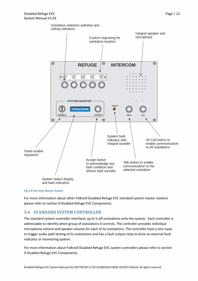
LevelOne
LevelTwo
LevelThree
LevelFour
LevelFive
FAULT
ACCEPTENABLE
SYSTEM NORMAL
SYSTEM MONITOR
TALK ALL
REFUGE INTERCOM
Talk button to enablecommunication to theselected outstation
All Call button toenable communicationto All outstations
System faultindicator withintegral sounder
Accept buttonto acknowledge anyfault condition andsilence fault sounder
Panel enablekeyswitch
System status displayand fault indication
Outstation selection switches andcalling indicators
Custom engraving foroutstation location
Integral speaker andmicrophone
Fig 3:4 Five Way Master Station
For more information about other Folknoll Disabled Refuge EVC standard system master stations
please refer to section 9 Disabled Refuge EVC Components.
3.4 STANDARD SYSTEM CONTROLLER
The standard system controller interfaces up to 5-off outstations onto the system. Each controller is
addressable to identify which group of outstations it controls. The controller provides individual
microphone volume and speaker volume for each of its outstations. The controller have a test input
to trigger audio path testing of its outstations and has a fault output relay to drive an external fault
indicator or monitoring system.
For more information about Folknoll Disabled Refuge EVC system controllers please refer to section
9 Disabled Refuge EVC Components.

Disabled Refuge EVC Page | 13 System Manual V1.03
Disabled Refuge EVC System Manual Doc RA7760.00 V1.03 25/08/2010 E&OE-©2010 Folknoll, all rights reserved
3.5 STANDARD SYSTEM FAULT MONITORING
Standard faults are reported by the standard system master station, please refer to section 7 System
Faults.
3.5.1 Standard System Audio Path Monitoring and Reporting
Standard Folknoll Disabled Refuge EVC systems have audio path monitoring and reporting. Audio
tones are sent to outstation speakers, received by outstation microphones and compared. Any
discrepancies are reported by the standard system compact master station, please refer to section 7
System Faults.
Standard system controllers will test its own outstations. To trigger a test apply a short to connector
J11 on each standard system controller. Each system controller can be triggered separately or
simultaneously as required. Please refer to section 9.9 Standard System Controller (P/N RA7700.02).
NOTE: Each system controller tests its own outstations. To test the entire system the short must
be applied to all system controllers.
If required audio path testing can be automated by connecting the standard system controller inputs
to an external timer or management system.
NOTE: During testing outstations will emit audio tones. Testing should be timed to minimise
inconvenience.
Each standard system controller has a fault output relay. This can be used to activate an external
indicator or management system. Connection is made to connect to relay output J6 please refer to
section 9.9 Standard System Controller (P/N RA7700.02).
NOTE: Each system controller sets an output depending on the results of testing its own
outstations. To detect all outstation fails the output from all system controllers must be
monitored.
3.6 STANDARD SYSTEM BATTERY BACKED PSU
All Folknoll compact and standard Disabled Refuge EVC systems can be powered from a single
battery backed PSU. In the event of a mains failure the backup unit is capable of providing at least 24
hours standby and 30 minutes operation. The mains supply is monitored and supply failures are
reported by the master station.
Standard system power is derived from the standard system PSU and standby battery set. This
combination will provide power for up to 20–off outstations, 4-off system controllers and one
master station.
For more information about Folknoll Disabled Refuge EVC PSUs and Battery Sets please refer to
section 9 Disabled Refuge EVC Components.

Disabled Refuge EVC Page | 14 System Manual V1.03
Disabled Refuge EVC System Manual Doc RA7760.00 V1.03 25/08/2010 E&OE-©2010 Folknoll, all rights reserved
3.7 STANDARD SYSTEM CABLING
Outstations are star wired to system controllers which are daisy chained to the master station.
Standard systems can be star wired back to a central point or to start wired distributed collection
points, enabling a variety of cabling options, particularly useful when retrofitting systems to existing
buildings.
NOTE: all type cables should conform to the relevant British Standards, fire resistant cabling may
be required e.g. FIRETUFdata, please refer to section 10 APPENDIX A FIRETUFdata.
3.7.1 Standard System Cabling layout
Each outstation is connected by a shielded 2 pair cable to its system controller.
The master station and all of the system controllers are looped together by a 3 pair cable.
The first system controller is connected to the PSU by 4 cores
The PSU is connected to a mains supply.
3.7.2 Standard System Cabling Rules
No termination resistors are required.
Assuming FIRETUFdata cable is used the maximum length of cable between each outstation
and its system Controller is 200m.
Assuming FIRETUFdata cable is used the maximum length of cable between each system
Controller is 200m.
Assuming FIRETUFdata cable is used the maximum length of cable between the first system
Controller and the master station is 200m.
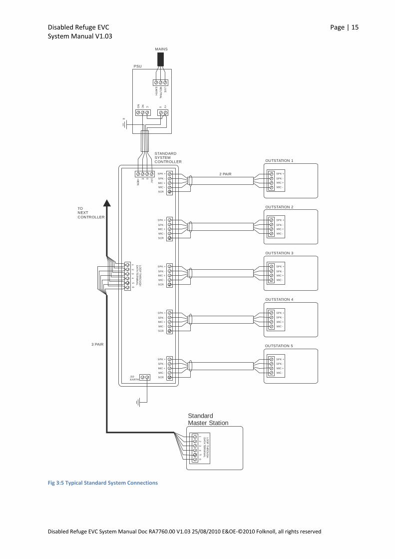
3.7.3 Standard System Cable Connections
All connection is via terminal block located within the equipment, ‘knockouts’ have been provided
for cable entry. Folknoll’s design has allowed sufficient room for glands for larger fire resistant cables
types to comply with BS requirements.
Please refer to the Drawing below:
Disabled Refuge EVC Page | 15 System Manual V1.03
Disabled Refuge EVC System Manual Doc RA7760.00 V1.03 25/08/2010 E&OE-©2010 Folknoll, all rights reserved
SPK -
MIC +
MIC -
SCR
SPK +
OUTSTATION 1
STANDARDSYSTEMCONTROLLER
SPK -
MIC +
MIC -
SCR
SPK +
SPK -
MIC +
MIC -
SCR
SPK +
SPK -
MIC +
MIC -
SCR
SPK +
SPK -
MIC +
MIC -
SCR
SPK +
LIV
E
EA
RT
H
NE
UT
RA
L
MAINS
24
V
+M
ON
E 0
0
+V
NO
NC C
E
PSU
J10EARTH
2 PAIR
23
45
16
LO
OP
TH
RO
UG
HD
AT
A T
ER
MIN
AL
3 PAIR
TONEXT
CONTROLLER
StandardMaster Station
23
45
16
LO
OP
TH
RO
UG
HD
AT
A T
ER
MIN
AL
OUTSTATION 4
OUTSTATION 3
OUTSTATION 2
SPK -
MIC +
MIC -
SPK +
SPK -
MIC +
MIC -
SPK +
SPK -
MIC +
MIC -
SPK +
SPK -
MIC +
MIC -
SPK +
SPK -
MIC +
MIC -
SPK +
OUTSTATION 5
Fig 3:5 Typical Standard System Connections

Disabled Refuge EVC Page | 16 System Manual V1.03
Disabled Refuge EVC System Manual Doc RA7760.00 V1.03 25/08/2010 E&OE-©2010 Folknoll, all rights reserved
4 INSTALLATION Mount the equipment and pull the required cables, please refer to section 2 Compact Disabled
Refuge EVC Systems or section 3 Standard Disabled Refuge EVC Systems as appropriate
Terminate the cables please refer to section 2.6.3 Compact System Cable Connections or section
3.7.3 Standard System Cable Connections as appropriate.
Do not power up, (please refer to Section 5 Commissioning below).
NOTE: cable and equipment should be installed in accordance with the current British Standards.
Disabled Refuge EVC Page | 17 System Manual V1.03
Disabled Refuge EVC System Manual Doc RA7760.00 V1.03 25/08/2010 E&OE-©2010 Folknoll, all rights reserved
5 COMMISSIONING
5.1 SYSTEM CONTROLLER ADDRESSING (STANDARD SYSTEM ONLY)
Each standard system controller must be “addressed” to identify which group of outstations it is
controlling. The controller is addressed using jumpers J8 (6-10) and J13 (11-15), please refer to
section 9.9 Standard System Controller (P/N RA7700.02). The jumpers should be set according to the
following table:-
System Controller for Outstations 1-5
System Controller for Outstations 6-10
System Controller for Outstations 11-15
System Controller for Outstations 15-20
J8 (6-10) UNLINKED LINKED UNLINKED LINKED
J13 (11-15) UNLINKED UNLINKED LINKED LINKED
Fig 5:1 Table of Jumper Settings for 'Addressing' Standard System Controllers
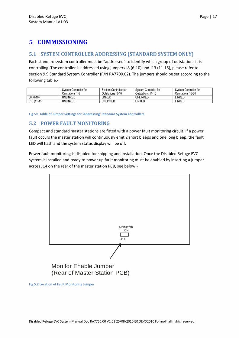
5.2 POWER FAULT MONITORING
Compact and standard master stations are fitted with a power fault monitoring circuit. If a power
fault occurs the master station will continuously emit 2 short bleeps and one long bleep, the fault
LED will flash and the system status display will be off.
Power fault monitoring is disabled for shipping and installation. Once the Disabled Refuge EVC
system is installed and ready to power up fault monitoring must be enabled by inserting a jumper
across J14 on the rear of the master station PCB, see below:-
Monitor Enable Jumper(Rear of Master Station PCB)
J14
MONITOR ON
Fig 5:2 Location of Fault Monitoring Jumper
Disabled Refuge EVC Page | 18 System Manual V1.03
Disabled Refuge EVC System Manual Doc RA7760.00 V1.03 25/08/2010 E&OE-©2010 Folknoll, all rights reserved
5.3 OUTSTATION CONFIGURATION
Outstation configuration is not required the system is automatically configured on power up. Please
refer to Section 5.5 Initial Power Up below.
5.4 ENABLE THE MASTER STATION KEYBOARD
The master station is fitted with a keyed enable switch to enable/disable the master Panel buttons
(keyboard), please refer to section 9 Disabled Refuge EVC Components. This switch is used to
prevent unauthorized persons operating the system and/or to enable the system in the event of
emergency. Ensure that this switch is set in the enable position, i.e. turn the key clockwise before
applying power to the system.
5.5 INITIAL POWER UP
Please refer to Section to section 9 Disabled Refuge EVC Components to familiarise yourself with the
layout of your master station keyboard.
When ready, power up the system.
If the system is powered up with the master station keyboard disabled the master station will
continuously emit 2 short bleeps and one long bleep, the fault LED will flash and the system status
display will show PLEASE ENABLE. Rotate the enable switch key clockwise and the power up
sequence will continue.
On system power up the master station will perform a self test. ‘POWER UP TEST’ will be displayed
on the system status display and the master station buttons will flash, check that all of the buttons
flash.
If the power up test is successful, the system will scan for outstations the system status display will
scroll DETECT SUBS PRESS ACCEPT. Press accept the ACCEPT button on the master station to start
the system scan. The system status display will scroll PLEASE WAIT followed by a list of outstations
detected followed by PRESS ACCEPT
Check the list of outstations is correct if the list is incorrect there may be a cabling fault or outstation
fault.
Press ACCEPT on the master station once more to start an audio test, please refer to Section 5.7
Audio Path Tests below. The system status display will scroll AUDIO TEST PLEASE WAIT. When the
test is completed the system will illuminate the buttons corresponding to the outstations that failed
the test and the system status display will scroll NOT FITTED? IS THIS CORRECT YES NO. Check that
the buttons illuminated as NOT FITTED are as expected.
NOTE: you may need to hold the ACCEPT button down for a short while.
If the correct buttons are not illuminated then one or more or the outstations will have failed the
audio test, there may be a cabling fault or an outstation fault.
If the correct buttons are illuminated then all of the outstations on the system have passed their test
and the system is ready for operation.

Disabled Refuge EVC Page | 19 System Manual V1.03
Disabled Refuge EVC System Manual Doc RA7760.00 V1.03 25/08/2010 E&OE-©2010 Folknoll, all rights reserved
To select YES or NO press the ACCEPT button when ’YES’ or NO is shown on the system status
display.
If NO is selected the system status display shows SYSTEM RESET fix the faults and power cycle the
system.
If YES is selected and the one or more of the detected outstations has failed the test, the system will
report the fault, please refer to section 7 System Faults below.
If ‘YES’ is selected and all of the detected outstations have passed the test the system will start
operating. The system status display will show PANEL ENABLED. If local operating procedures
require disable the master station keyboard using the keyed enable switch if disabled the system
status display will show SYSTEM NORMAL.
5.6 VOLUME ADJUSTMENT
Once installed and powered up the microphone and speaker volume for each outstation should be
adjusted to suite its location.
Variable resistors are available to adjust each outstation microphone speaker volumes, please refer
to section 9.3 Compact System 5 Way Master Station (P/N RA7805.01), 9.4 Compact System 10 Way
Master Station (P/N RA7810.01) or 9.9Standard System Controller (P/N RA7700.02) to locate these
variable resistors.
Visit each outstation in turn and set the audio levels at its system controller as required.
5.7 AUDIO PATH TESTS (MICROPHONE AND SPEAKERTESTS)
Cause a fault at one or more outstations by blocking the microphone or disconnecting the speaker
circuit(s). Trigger an audio circuit test by shorting the input(s) on the compact system master or
standard system controller(s). Check the system reports audio path failure for the correct
outstation(s), please refer to section 7 System Faults. Check the audio fault outputs are also
triggered.
Configure the external audio path test trigger device as required, and connect to the input(s) on the
compact system master or standard system controller(s).
If required, configure the fault indicators or monitoring system. Connect to the compact master or
system controller(s) audio path fault output(s). If possible trigger a test and check that all systems
respond correctly.
Check that any fitted external timers or management systems trigger audio path tests as configured.
Disabled Refuge EVC Page | 20 System Manual V1.03
Disabled Refuge EVC System Manual Doc RA7760.00 V1.03 25/08/2010 E&OE-©2010 Folknoll, all rights reserved
6 OPERATION For the purposes of this manual we will refer to persons using the system from a refuge area as
users, and persons operating the system from the master station as operators. For a diagram of your
master station, please refer to section 9 Disabled Refuge EVC Components.
NOTE: this system should be operated in accordance to the relevant British Standards.
6.1 ENABLING THE MASTER STATION
The master station is fitted with a keyed enable switch to enable/disable the master panel buttons.
This is used to prevent unauthorized persons operating the system and/or to enable the system in
the event of emergency.
Before operating the system ensure that the system has been enabled by the appropriate persons
according to local procedures i.e. turn the enable switch key clockwise. The system status panel will
show ‘PANEL ENABLED’.
If required by local procedures disable the master station keyboard after use, i.e. turn the enable
switch key anti-clockwise. The system status panel will show ‘SYSTEM NORMAL’.
6.2 ACCEPTING CALLS FROM OUTSTATIONS
When a user presses the call button on an outstation:-
The outstation LED will flash.
The master station sounder will sound (buzz).
The button on the master station corresponding to the outstation will flash red.
The operator can accept the call by pressing the flashing button corresponding to the outstation,
when accepted:-
The LED on the corresponding outstation will be illuminated.
The master station sounder will cease.
The button on the master station corresponding to the outstation will be illuminated (not
flashing).
The operator will be able to hear the user.
To talk to the user the operator must hold down the TALK button.
Whilst the TALK button is pressed the operator will not be able to hear the user.
To cancel the call the operator presses the illuminated button corresponding to the user’s
outstation.
The LED on the corresponding outstation will no longer be illuminated.
The button on the master station corresponding to the outstation will no longer be
illuminated.
NOTE: the Folknoll Disabled Refuge EVC system is a Push to Talk (PTT) system. The operator must
hold down the TALK button to talk to the user.

Disabled Refuge EVC Page | 21 System Manual V1.03
Disabled Refuge EVC System Manual Doc RA7760.00 V1.03 25/08/2010 E&OE-©2010 Folknoll, all rights reserved
6.3 MAKING CALLS TO OUTSTATIONS
To call an outstation the operator presses the button corresponding to the required outstation, once
pressed:-
The LED on the corresponding outstation will be illuminated.
The button on the master station corresponding to the outstation will be illuminated (not
flashing).
The operator will now be able to hear the user.
To talk to the user the operator must hold down the TALK button.
To cancel the call the operator presses the illuminated button corresponding to the user’s
outstation.
The LED on the corresponding outstation will no longer be illuminated.
The button on the master station button corresponding to the outstation will no longer be
illuminated.
6.4 ALL CALLS
To talk to all of the outstations simultaneously (the operator cannot hear the outstations), for
example to make a reassurance announcement the operator presses and holds down the ALL
button. Once held down:-
The LEDs on all of the outstations will be illuminated.
The buttons on the master station corresponding to all of the connected outstations will be
illuminated.
The system status display will show ‘ALL CALL ACTIVE’
The operator will be heard at all outstations.
To end the all call release the ALL button.
The LEDs on all of the outstations will no longer be illuminated.
The buttons corresponding to all of the connected outstations will no longer be illuminated.
The system status display will briefly show ‘ALL CALL END’ followed by ‘PANEL ENABLED’
The operator will no longer be heard at any of the outstations.
NOTE: the Folknoll Disabled Refuge EVC system is a Push to Talk (PTT) system. The operator must
hold down the ALL button to talk all of the outstations.
Disabled Refuge EVC Page | 22 System Manual V1.03
Disabled Refuge EVC System Manual Doc RA7760.00 V1.03 25/08/2010 E&OE-©2010 Folknoll, all rights reserved
6.5 FAULTS
The system automatically monitors and reports faults. Faults are usually indicated by the master
station sounder and fault LED activating for 2 short bleeps and one long bleep continuously. An error
message is usually shown on the system status display.
Usually the sounder can be silenced and the fault LED turned off by pressing the ACCEPT button, any
fault message will remain on the system status display. Please refer to section 7 System Faults for
further information.
The fault should be reported or repaired according to local procedures.
NOTE: Any temporary measures e.g. partial closures required by the nature of the fault, site
conditions, local regulations and procedures should be put into effect immediately.
Please refer to section 7 System Faults.
6.6 MANUAL SYSTEM TEST (COMPACT SYSTEMS ONLY)
To initiate start a system test, press the TEST button on the compact system master station. The
system will test each outstation intern and report any errors found.
NOTE: During testing outstations will generate audio tones. Testing should be timed to minimise
inconvenience.
If an error is detected the sounder can be silenced and the fault LED turned off by pressing the
ACCEPT button, any fault message will remain on the system status display. Please refer to section 7
System Faults for further information.
The fault should be reported or repaired according to local procedures.
NOTE: Any temporary measures e.g. partial closures required by the nature of the fault, site
conditions, local regulations and procedures should be put into effect immediately.
Disabled Refuge EVC Page | 23 System Manual V1.03
Disabled Refuge EVC System Manual Doc RA7760.00 V1.03 25/08/2010 E&OE-©2010 Folknoll, all rights reserved
7 SYSTEM FAULTS The system automatically monitors and reports faults. Faults are usually indicated by the master
station sounder and fault LED activating for 2 short bleeps and one long bleep continuously. An error
message is usually shown on the system status display.
Usually the sounder can be silenced and the fault LED turned off by pressing the ACCEPT button, any
fault message will remain on the system status display.
The fault should be reported / repaired according to local procedures.
NOTE: Any temporary measures e.g. partial closures required by the nature of the fault, site
conditions, local regulations and procedures should be put into effect immediately.
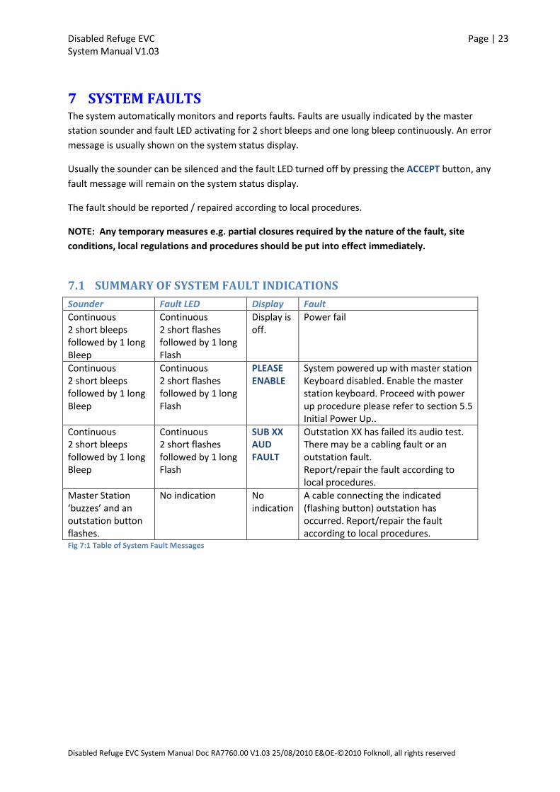
7.1 SUMMARY OF SYSTEM FAULT INDICATIONS
Sounder Fault LED Display Fault
Continuous 2 short bleeps followed by 1 long Bleep
Continuous 2 short flashes followed by 1 long Flash
Display is off.
Power fail
Continuous 2 short bleeps followed by 1 long Bleep
Continuous 2 short flashes followed by 1 long Flash
PLEASE ENABLE
System powered up with master station Keyboard disabled. Enable the master station keyboard. Proceed with power up procedure please refer to section 5.5 Initial Power Up..
Continuous 2 short bleeps followed by 1 long Bleep
Continuous 2 short flashes followed by 1 long Flash
SUB XX AUD FAULT
Outstation XX has failed its audio test. There may be a cabling fault or an outstation fault. Report/repair the fault according to local procedures.
Master Station ‘buzzes’ and an outstation button flashes.
No indication No indication
A cable connecting the indicated (flashing button) outstation has occurred. Report/repair the fault according to local procedures.
Fig 7:1 Table of System Fault Messages
Disabled Refuge EVC Page | 24 System Manual V1.03
Disabled Refuge EVC System Manual Doc RA7760.00 V1.03 25/08/2010 E&OE-©2010 Folknoll, all rights reserved
7.2 MAINS POWER FAIL
The master station will continuously emit 2 short bleeps and one long bleep
The master station fault LED will continuously give 2 short flashes and one long flash in time
with the sounder.
The system status display will be off.
The system will continue to operate from its standby power supply. If fully charged the
system will remain on standby for at least 24 hours and allow 30 minutes of operation (calls
announcements etc.).
The sounder can be silenced and the fault LED turned off by pressing the ACCEPT button,
any fault message will remain on the system status display.
The mains supply should be restored as soon as possible.
NOTE: If the power is not restored the standby batteries will ‘run out’ and the system will cease to
be operational.
7.3 SYSTEM POWERED WITH MASTER STATION DISABLED
The master station will continuously emit 2 short bleeps and one long bleep
The master station fault LED will continuously give 2 short flashes and one long flash in time
with the sounder.
The system status display will show PLEASE ENABLE.
To rectify the fault turn the keyed enabled switch and complete the power up procedure,
please refer to section 5.5 Initial Power Up.
This situation should only occur during installation and maintenance.
NOTE: The system will not be operational until the power up procedure has been completed.
7.4 AUDIO PATH FAULT
Audio path tests are performed on initial power up and as triggered by the external timer or
management system. If an outstation fails an audio path test:-
The master station will continuously emit 2 short bleeps and one long bleep
The master station fault LED will continuously give 2 short flashes and one long flash in time
with the sounder.
The fault will be shown on the system status display. E.g. SUB XX AUD FAULT
The sounder can be silenced and the fault LED turned off by pressing the ACCEPT button,
any fault message will remain on the system status display.
The fault should be reported / repaired according to the local fault reporting procedure.
NOTE: The SUB or outstation indicated may not be operational until the fault is rectified.

Disabled Refuge EVC Page | 25 System Manual V1.03
Disabled Refuge EVC System Manual Doc RA7760.00 V1.03 25/08/2010 E&OE-©2010 Folknoll, all rights reserved
7.5 OUTSTATION CABLE DISCONNECTED
The master station will ‘buzz’ and the button on the master station corresponding to the
outstation will flash.
The ‘buzz’ can be silenced by accepting the call by pressing the button on the master station
corresponding to the outstation.
The fault should be reported / repaired according to the local fault reporting procedure.
NOTE: The SUB or outstation indicated will not be operational until the fault is rectified.
Disabled Refuge EVC Page | 26 System Manual V1.03
Disabled Refuge EVC System Manual Doc RA7760.00 V1.03 25/08/2010 E&OE-©2010 Folknoll, all rights reserved
8 ROUTINE MAINTENANCE AND TESTING This section gives a generic guide to the routine maintenance and testing of Folknoll Disabled Refuge
EVC systems. Local maintenance, testing and repair procedures should be implemented according to
local regulations, procedures, site conditions, risk assessment, and equipment installed.
Disabled Refuge EVC systems are usually only used in the event of an emergency. Faults and other
issues that develop may not be discovered until an emergency arises and the system is required. It is
important that routine maintenance and frequent testing is carried out to ensure that the system is
fully operational.
The system should be configured for automatic audio path testing,
!!may be automatic may be boot only!! The system will automatically test audio paths, reporting
faults to the operator and any local alarm gathering systems e.g. BMS. !!
8.1 ROUTINE MAINTENANCE
Folknoll Disabled Refuge EVC systems require minimal maintenance. The systems are robustly
designed and have low wear as they are only used in emergency. The only parts to require regular
maintenance are the PSU standby batteries.
8.1.1 Standby Batteries
The PSU backup batteries should be replaced as the battery manufacturer advises or at least every 3
years.
8.2 VISUAL INSPECTION
Disabled Refuge EVC systems are usually located in ‘public’ areas and depending on location can be
open to abuse. The frequency of visual inspections should be determined by local regulations,
procedures, site conditions, risk assessment and experience.
8.2.1 Outstations
System outstations should undergo frequent visual inspections to check:
Outstations and signage are clearly visible and accessible by disabled persons, e.g. not
hidden by posters, or behind a large object such as a roll cage, in a restricted area etc.
Outstations show no signs of physical damage e.g. water ingress, impact.
Outstations show no signs of other forms of abuse e.g. chewing gum in the microphone hole
etc.
Outstations show no signs of any other forms of damage that might affect visibility, access or
operation.
8.2.2 Master Station
The master station should undergo frequent visual inspections to check:

Disabled Refuge EVC Page | 27 System Manual V1.03
Disabled Refuge EVC System Manual Doc RA7760.00 V1.03 25/08/2010 E&OE-©2010 Folknoll, all rights reserved
The master station and any signage are clearly visible and accessible by disabled persons,
e.g. not hidden by posters, or behind a large object such as a roll cage, in a restricted area
etc.
The master stations show no signs of physical damage e.g. water ingress, impact.
The master stations show no signs of other forms of abuse e.g. chewing gum in the
microphone hole etc.
The master stations show no signs of any other forms of damage that might affect visibility,
access or operation.
The master station enable key is present and accessible by all authorised operators.
8.2.3 Control Equipment (Standard System Only)
Any control equipment and exposed cable routes should undergo regular visual inspections to check:
All control equipment and exposed cable routes show no signs of physical damage e.g. water
ingress, impact.
All control equipment and exposed cable routes show no signs of other forms of abuse
All control equipment and exposed cable routes show no signs of any other forms of damage
that might affect operation.
8.3 FUNCTIONAL TESTING
The system should undergo frequent functional testing to ensure that the system is ready for
emergency operation.
8.3.1 User Call Check
For each outstation check the following:
A call to the master station can be initiated by the outstation user.
The master station responds correctly and the master station operator can accept the call.
The outstation user can be clearly heard by the master station operator.
The master station operator can be clearly heard by the outstation user.
The call can be cancelled by the master station operator.
8.3.2 Operator Call Check
For each outstation check the following:
A call to the outstation can be initiated by the master station user.
The outstation user can be clearly heard by the master station operator.
The master station operator can be clearly heard by the outstation user.
The call can be cancelled by the master station operator.
8.3.3 All Call Check
For each outstation check the following:
An all call can be initiated by the master station user.
The master station operator can be clearly heard by the outstation user.
The all call can be cancelled by the master station operator.
Disabled Refuge EVC Page | 28 System Manual V1.03
Disabled Refuge EVC System Manual Doc RA7760.00 V1.03 25/08/2010 E&OE-©2010 Folknoll, all rights reserved
8.3.4 Standby Operation Test
Disconnect the mains supply and check the following:
The master station reports power fail and the sounder can be silenced by pressing the
master station ACCEPT button.
Standard systems only check the PSU unit local alarm sounds and can be silenced, by
pressing the PSU unit SILENCE button.
The system is still operational (check that calls can be made).
Restore the mains supply and check the following:
The master station no longer reports mains fail.
The system is still operational (check that calls can be made).
8.3.5 Standby Time Test
If required by local regulations or procedures test the standby time by checking how the mains can
be disconnected before the system fails.
The PSU should disconnect the batteries at 19V to prevent full discharge.
NOTE: this test should not be carried out on a live system because:
The system will fail at some point.
When the power is restored the standby time will be reduced.
Either of these conditions may violate site operation conditions and require closure of the site.
8.3.6 Standby Battery Charging Voltage Test
–
. No adjustment possible.
8.3.7 Audio Path Test
To verify that the system responds correctly in the event of an audio path test failure, cause a failure
by covering an outstation microphone or disconnecting an outstation speaker circuit.
Start an audio path test:
On compact systems – Press the TEST button on the compact master station.
On standard systems - If possible cause the external timer or management system to initiate a test,
alternatively short the test inputs on the standard system controllers, please refer to section 9.9
Standard System Controller (P/N RA7700.02).
Audio path tests are triggered automatically by an external timer or management system.
Check that the master station correctly reports the outstation failure(s) and that any external
indicators or management systems respond correctly.
Disabled Refuge EVC Page | 29 System Manual V1.03
Disabled Refuge EVC System Manual Doc RA7760.00 V1.03 25/08/2010 E&OE-©2010 Folknoll, all rights reserved
8.3.8 Automatic Audio Path Testing
Check that the automatic audio path testing is triggered at the times configured.
For compact systems this may be the internal timer or an external trigger system.
For standard systems this will be an external trigger system, e.g. timer or management system.
Disabled Refuge EVC Page | 30 System Manual V1.03
Disabled Refuge EVC System Manual Doc RA7760.00 V1.03 25/08/2010 E&OE-©2010 Folknoll, all rights reserved
9 DISABLED REFUGE EVC COMPONENTS
9.1 EXTERNAL OUTSTATION (P/N RA7700.60)
REFUGE ALARM
PRESS ONCE TO CALL
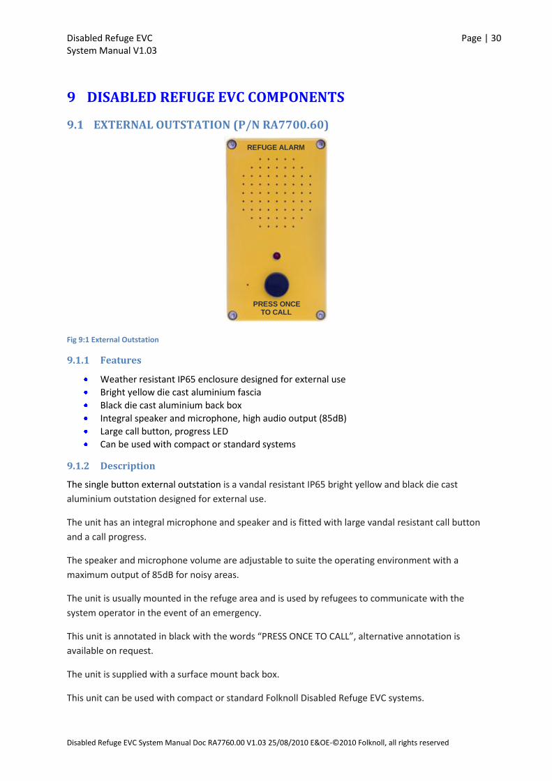
Fig 9:1 External Outstation
9.1.1 Features
Weather resistant IP65 enclosure designed for external use
Bright yellow die cast aluminium fascia
Black die cast aluminium back box
Integral speaker and microphone, high audio output (85dB)
Large call button, progress LED
Can be used with compact or standard systems
9.1.2 Description
The single button external outstation is a vandal resistant IP65 bright yellow and black die cast
aluminium outstation designed for external use.
The unit has an integral microphone and speaker and is fitted with large vandal resistant call button
and a call progress.
The speaker and microphone volume are adjustable to suite the operating environment with a
maximum output of 85dB for noisy areas.
The unit is usually mounted in the refuge area and is used by refugees to communicate with the
system operator in the event of an emergency.
This unit is annotated in black with the words “PRESS ONCE TO CALL”, alternative annotation is
available on request.
The unit is supplied with a surface mount back box.
This unit can be used with compact or standard Folknoll Disabled Refuge EVC systems.

Disabled Refuge EVC Page | 31 System Manual V1.03
Disabled Refuge EVC System Manual Doc RA7760.00 V1.03 25/08/2010 E&OE-©2010 Folknoll, all rights reserved
9.1.3 Parts
RA7700.60 Surface mount, aluminium, vandal resistant outstation
9.1.4 Specifications
Fascia: Aluminium, bright yellow finish, black annotation Surface back box: Mild steel, black finish Dimensions: Width:130mm, Height:190mm, (approx.) Power: Line powered Audio output: Max 85dB
9.1.5 Connections
Outstation
SP
K -
MIC
+
MIC
-
SP
K +
Fig 9:2 Outstation Connections
Disabled Refuge EVC Page | 32 System Manual V1.03
Disabled Refuge EVC System Manual Doc RA7760.00 V1.03 25/08/2010 E&OE-©2010 Folknoll, all rights reserved
9.2 INTERNAL OUTSTATION (P/N RA7700.30 AND RA7700.35)
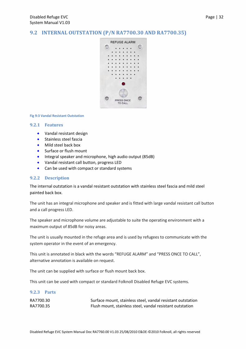
Fig 9:3 Vandal Resistant Outstation
9.2.1 Features
Vandal resistant design
Stainless steel fascia
Mild steel back box
Surface or flush mount
Integral speaker and microphone, high audio output (85dB)
Vandal resistant call button, progress LED
Can be used with compact or standard systems
9.2.2 Description
The internal outstation is a vandal resistant outstation with stainless steel fascia and mild steel
painted back box.
The unit has an integral microphone and speaker and is fitted with large vandal resistant call button
and a call progress LED.
The speaker and microphone volume are adjustable to suite the operating environment with a
maximum output of 85dB for noisy areas.
The unit is usually mounted in the refuge area and is used by refugees to communicate with the
system operator in the event of an emergency.
This unit is annotated in black with the words “REFUGE ALARM” and “PRESS ONCE TO CALL”,
alternative annotation is available on request.
The unit can be supplied with surface or flush mount back box.
This unit can be used with compact or standard Folknoll Disabled Refuge EVC systems.
9.2.3 Parts
RA7700.30 Surface mount, stainless steel, vandal resistant outstation RA7700.35 Flush mount, stainless steel, vandal resistant outstation
Disabled Refuge EVC Page | 33 System Manual V1.03
Disabled Refuge EVC System Manual Doc RA7760.00 V1.03 25/08/2010 E&OE-©2010 Folknoll, all rights reserved
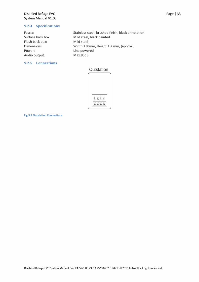
9.2.4 Specifications
Fascia: Stainless steel, brushed finish, black annotation Surface back box: Mild steel, black painted Flush back box: Mild steel Dimensions: Width:130mm, Height:190mm, (approx.) Power: Line powered Audio output: Max:85dB
9.2.5 Connections
Outstation
SP
K -
MIC
+
MIC
-
SP
K +
Fig 9:4 Outstation Connections

Disabled Refuge EVC Page | 34 System Manual V1.03
Disabled Refuge EVC System Manual Doc RA7760.00 V1.03 25/08/2010 E&OE-©2010 Folknoll, all rights reserved
9.3 COMPACT SYSTEM 5 WAY MASTER STATION (P/N RA7805.01)
TALK ALLACCEPT TEST FAULT
REFUGE INTERCOM
63 x 12mm Cutout
SYSTEM MONITOR 1 2 3 4 5
ENABLE
Fig 9:5 Compact System Five Way Master Station
9.3.1 Features
Controls up to 5-off outstations
Keyed enable switch
LCD system status display
Fault LED
Internal speaker ,internal microphone
High audio output for noisy environments (85dB)
Audio path fault monitoring and reporting, internal and external triggers.
Mains supply monitoring and reporting
I/O for BMS or other external systems
Matches standard fire panel size and quality.
Customisable area label
Surface semi flush mount
Security screws
9.3.2 Description
The compact system 5 way master station is a surface/flush wall mounted master station for
Disabled Refuge EVCsystems of up to 5 outstations.
All compact system master stations are designed to match standard fire panel size and quality.
Disabled Refuge EVC Page | 35 System Manual V1.03
Disabled Refuge EVC System Manual Doc RA7760.00 V1.03 25/08/2010 E&OE-©2010 Folknoll, all rights reserved
The unit has an integral microphone, speaker, system controller, PSU and standby batteries. The unit
is fitted with an LCD display, keyed enable switch, fault LED and large control buttons.
The speaker and microphone volume are adjustable to suite the operating environment with a
maximum output of 85dB for noisy areas.
The unit is usually mounted in the control area and is used by the system operator to communicate
with the system users in the event of an emergency.
This unit is annotated in black, alternative annotation is available on request.
A refuge area label is provided for noting meaningful refuge area names. The refuge area label and a
simplified operating instruction label are mounted on the front panel of the master station to aid
operators. A copy of the refuge area label may be found in section 11 APPENDIX B Compact System
Master Station Labels.
9.3.3 Parts
RA7805.01 5 way surface mount compact system master station RA7850.00 Bezel for semi flush mount RA7750.00 Battery set
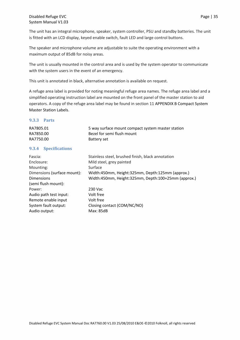
9.3.4 Specifications
Fascia: Stainless steel, brushed finish, black annotation Enclosure: Mild steel, grey painted Mounting: Surface Dimensions (surface mount): Width:450mm, Height:325mm, Depth:125mm (approx.) Dimensions (semi flush mount):
Width:450mm, Height:325mm, Depth:100+25mm (approx.)
Power: 230 Vac Audio path test input: Volt free Remote enable input Volt free System fault output: Closing contact (COM/NC/NO) Audio output: Max: 85dB
Disabled Refuge EVC Page | 36 System Manual V1.03
Disabled Refuge EVC System Manual Doc RA7760.00 V1.03 25/08/2010 E&OE-©2010 Folknoll, all rights reserved
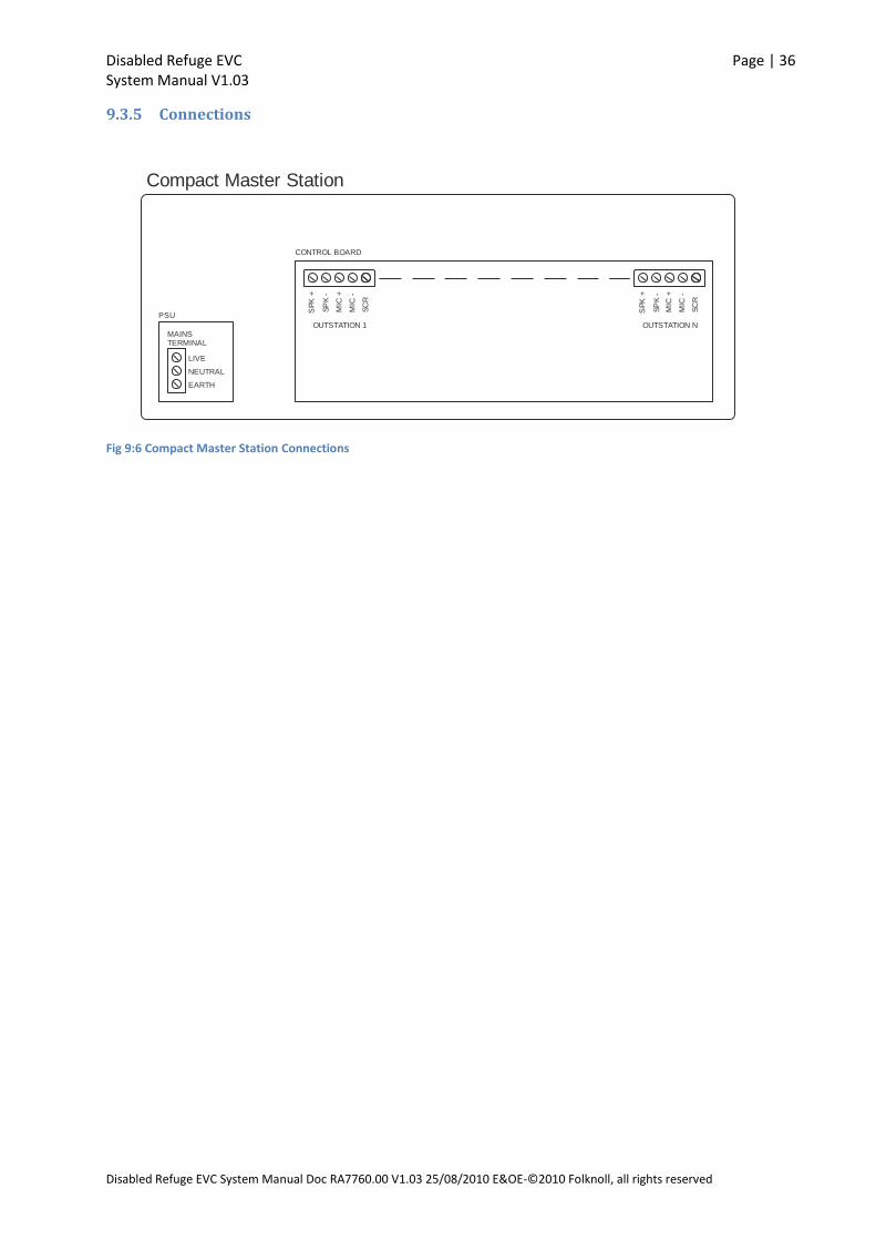
9.3.5 Connections
LIVE
EARTH
NEUTRAL
SP
K -
MIC
+
MIC
-
SC
R
SP
K +
SP
K -
MIC
+
MIC
-
SC
R
SP
K +
Compact Master Station
OUTSTATION 1 OUTSTATION NMAINSTERMINAL
CONTROL BOARD
PSU
Fig 9:6 Compact Master Station Connections

Disabled Refuge EVC Page | 37 System Manual V1.03
Disabled Refuge EVC System Manual Doc RA7760.00 V1.03 25/08/2010 E&OE-©2010 Folknoll, all rights reserved
9.4 COMPACT SYSTEM 10 WAY MASTER STATION (P/N RA7810.01)
Fig 9:7 Compact System Ten Way Master Station
9.4.1 Features
Controls up to 10-off outstations
Keyed enable switch
LCD system status display
Fault LED
Internal speaker ,internal microphone
High audio output for noisy environments (85dB)
Audio path fault monitoring and reporting, internal and external triggers.
Mains supply monitoring and reporting
I/O for BMS or other external systems
Matches standard fire panel size and quality.
Customisable area label
Surface or semi flush mount
Security screws
9.4.2 Description
The compact system 10 way master station is a surface/flush wall mounted master station for
Disabled Refuge EVCsystems of up to 10 outstations.
All compact system master stations are designed to match standard fire panel size and quality.
TALK ALLACCEPT TEST FAULT
REFUGE INTERCOM
63 x 12mm Cutout
SYSTEM MONITOR
6
1
7
2
8
3
9
4
10
5
ENABLE

Disabled Refuge EVC Page | 38 System Manual V1.03
Disabled Refuge EVC System Manual Doc RA7760.00 V1.03 25/08/2010 E&OE-©2010 Folknoll, all rights reserved
The unit has an integral microphone, speaker, system controller, PSU and standby batteries. The unit
is fitted with an LCD display, keyed enable switch, fault LED and large control buttons.
The speaker and microphone volume are adjustable to suite the operating environment with a
maximum output of 85dB for noisy areas.
The unit is usually mounted in the control area and is used by the system operator to communicate
with the system users in the event of an emergency.
This unit is annotated in black, alternative annotation is available on request.
A refuge area label is provided for noting meaningful refuge area names. The refuge area label and a
simplified operating instruction label are mounted on the front panel of the master station to aid
operators. A copy of the refuge area label may be found in section 11 APPENDIX B Compact System
Master Station Labels.
9.4.3 Parts
RA7810.01 10 way surface mount compact system master station RA7850.00 Bezel for semi flush mount RA7750.00 Battery set
9.4.4 Specifications
Fascia: Stainless steel; brushed finish; black annotation. Enclosure: Mild steel; grey painted Mounting: Surface Dimensions (surface mount): Width:450mm, Height:325mm, Depth:125mm (approx.) Dimensions (semi flush mount):
Width:450mm, Height:325mm, Depth:100+25mm (approx.)
Power: 230 Vac Audio path test input: Volt free Remote enable input: Volt free System fault output: Closing contact (COM/NC/NO) Audio output: Max: 85dB

Disabled Refuge EVC Page | 39 System Manual V1.03
Disabled Refuge EVC System Manual Doc RA7760.00 V1.03 25/08/2010 E&OE-©2010 Folknoll, all rights reserved
9.4.5 Connections
LIVE
EARTH
NEUTRAL
SP
K -
MIC
+
MIC
-
SC
R
SP
K +
SP
K -
MIC
+
MIC
-
SC
R
SP
K +
Compact Master Station
OUTSTATION 1 OUTSTATION NMAINSTERMINAL
CONTROL BOARD
PSU
Fig 9:8 Compact Master Station Connections
Disabled Refuge EVC Page | 40 System Manual V1.03
Disabled Refuge EVC System Manual Doc RA7760.00 V1.03 25/08/2010 E&OE-©2010 Folknoll, all rights reserved
9.5 STANDARD SYSTEM 5 WAY MASTER STATION (P/N RA7705.01 RA7705.05)
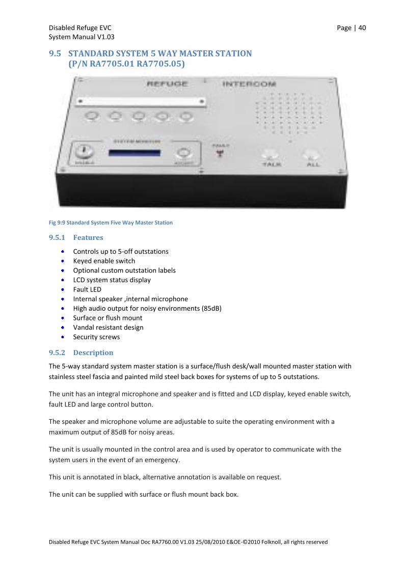
Fig 9:9 Standard System Five Way Master Station
9.5.1 Features
Controls up to 5-off outstations
Keyed enable switch
Optional custom outstation labels
LCD system status display
Fault LED
Internal speaker ,internal microphone
High audio output for noisy environments (85dB)
Surface or flush mount
Vandal resistant design
Security screws
9.5.2 Description
The 5-way standard system master station is a surface/flush desk/wall mounted master station with
stainless steel fascia and painted mild steel back boxes for systems of up to 5 outstations.
The unit has an integral microphone and speaker and is fitted and LCD display, keyed enable switch,
fault LED and large control button.
The speaker and microphone volume are adjustable to suite the operating environment with a
maximum output of 85dB for noisy areas.
The unit is usually mounted in the control area and is used by operator to communicate with the
system users in the event of an emergency.
This unit is annotated in black, alternative annotation is available on request.
The unit can be supplied with surface or flush mount back box.
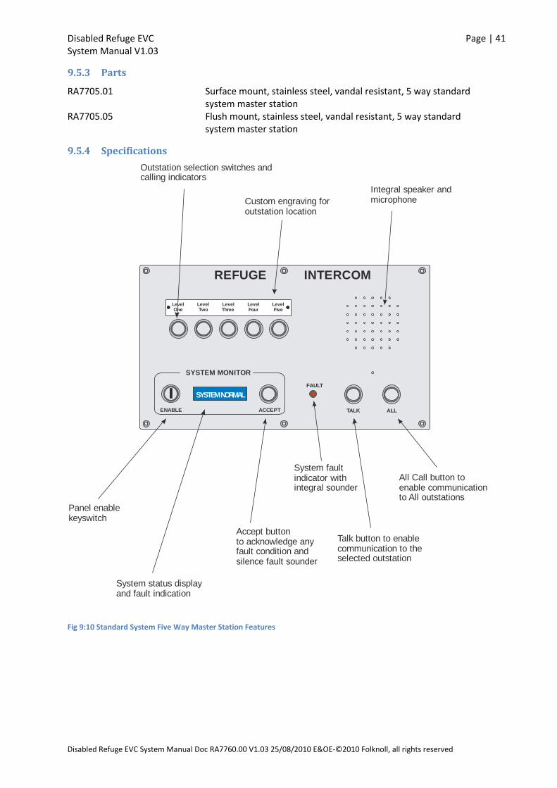
Disabled Refuge EVC Page | 41 System Manual V1.03
Disabled Refuge EVC System Manual Doc RA7760.00 V1.03 25/08/2010 E&OE-©2010 Folknoll, all rights reserved
9.5.3 Parts
RA7705.01 Surface mount, stainless steel, vandal resistant, 5 way standard system master station
RA7705.05 Flush mount, stainless steel, vandal resistant, 5 way standard system master station
9.5.4 Specifications
LevelOne
LevelTwo
LevelThree
LevelFour
LevelFive
FAULT
ACCEPTENABLE
SYSTEM NORMAL
SYSTEM MONITOR
TALK ALL
REFUGE INTERCOM
Talk button to enablecommunication to theselected outstation
All Call button toenable communicationto All outstations
System faultindicator withintegral sounder
Accept buttonto acknowledge anyfault condition andsilence fault sounder
Panel enablekeyswitch
System status displayand fault indication
Outstation selection switches andcalling indicators
Custom engraving foroutstation location
Integral speaker andmicrophone
Fig 9:10 Standard System Five Way Master Station Features
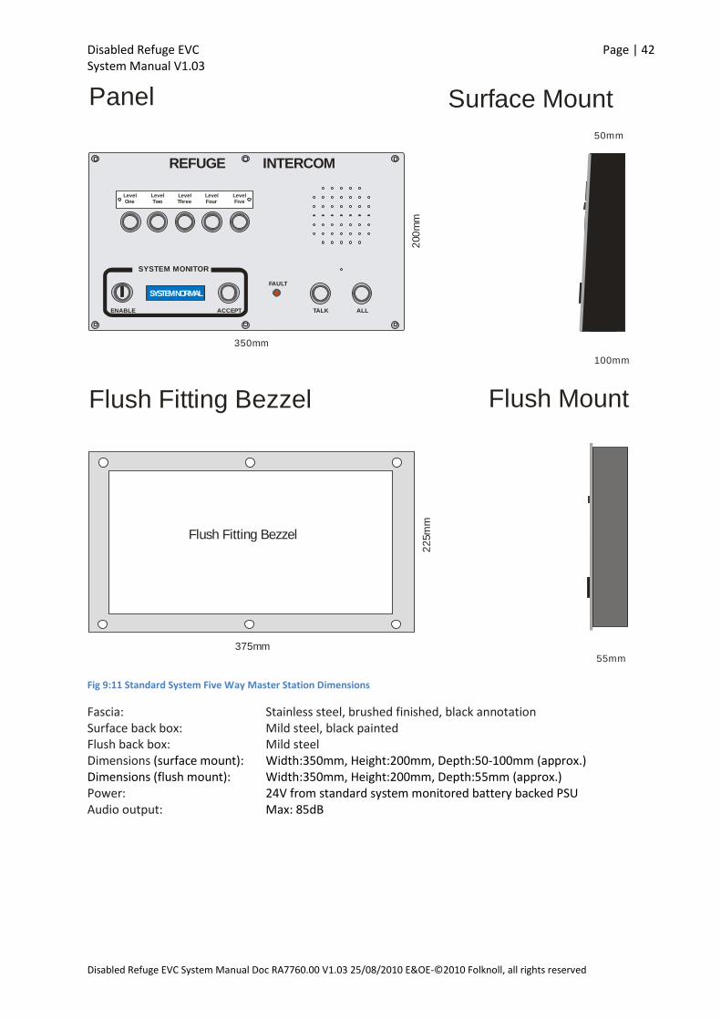
Disabled Refuge EVC Page | 42 System Manual V1.03
Disabled Refuge EVC System Manual Doc RA7760.00 V1.03 25/08/2010 E&OE-©2010 Folknoll, all rights reserved
LevelOne
LevelTwo
LevelThree
LevelFour
LevelFive
FAULT
ACCEPTENABLE
SYSTEM NORMAL
SYSTEM MONITOR
TALK ALL
REFUGE INTERCOM
350mm
200
mm
375mm
22
5m
m
Flush Fitting Bezzel
Panel
Flush Fitting Bezzel
Surface Mount
Flush Mount
55mm
100mm
50mm
Fig 9:11 Standard System Five Way Master Station Dimensions
Fascia: Stainless steel, brushed finished, black annotation Surface back box: Mild steel, black painted Flush back box: Mild steel Dimensions (surface mount): Width:350mm, Height:200mm, Depth:50-100mm (approx.) Dimensions (flush mount): Width:350mm, Height:200mm, Depth:55mm (approx.) Power: 24V from standard system monitored battery backed PSU Audio output: Max: 85dB
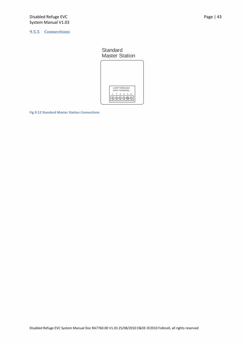
Disabled Refuge EVC Page | 43 System Manual V1.03
Disabled Refuge EVC System Manual Doc RA7760.00 V1.03 25/08/2010 E&OE-©2010 Folknoll, all rights reserved
9.5.5 Connections
StandardMaster Station
2 3 4 51 6
LOOP THROUGHDATA TERMINAL
Fig 9:12 Standard Master Station Connections
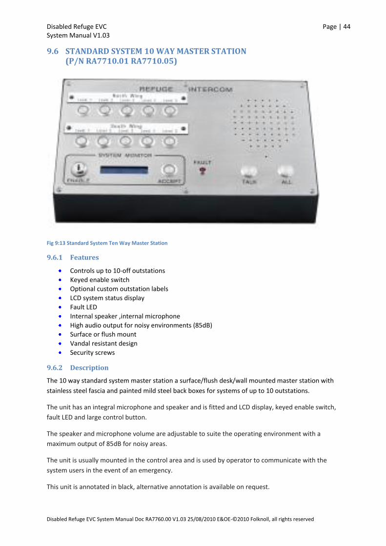
Disabled Refuge EVC Page | 44 System Manual V1.03
Disabled Refuge EVC System Manual Doc RA7760.00 V1.03 25/08/2010 E&OE-©2010 Folknoll, all rights reserved
9.6 STANDARD SYSTEM 10 WAY MASTER STATION (P/N RA7710.01 RA7710.05)
Fig 9:13 Standard System Ten Way Master Station
9.6.1 Features
Controls up to 10-off outstations
Keyed enable switch
Optional custom outstation labels
LCD system status display
Fault LED
Internal speaker ,internal microphone
High audio output for noisy environments (85dB)
Surface or flush mount
Vandal resistant design
Security screws
9.6.2 Description
The 10 way standard system master station a surface/flush desk/wall mounted master station with
stainless steel fascia and painted mild steel back boxes for systems of up to 10 outstations.
The unit has an integral microphone and speaker and is fitted and LCD display, keyed enable switch,
fault LED and large control button.
The speaker and microphone volume are adjustable to suite the operating environment with a
maximum output of 85dB for noisy areas.
The unit is usually mounted in the control area and is used by operator to communicate with the
system users in the event of an emergency.
This unit is annotated in black, alternative annotation is available on request.
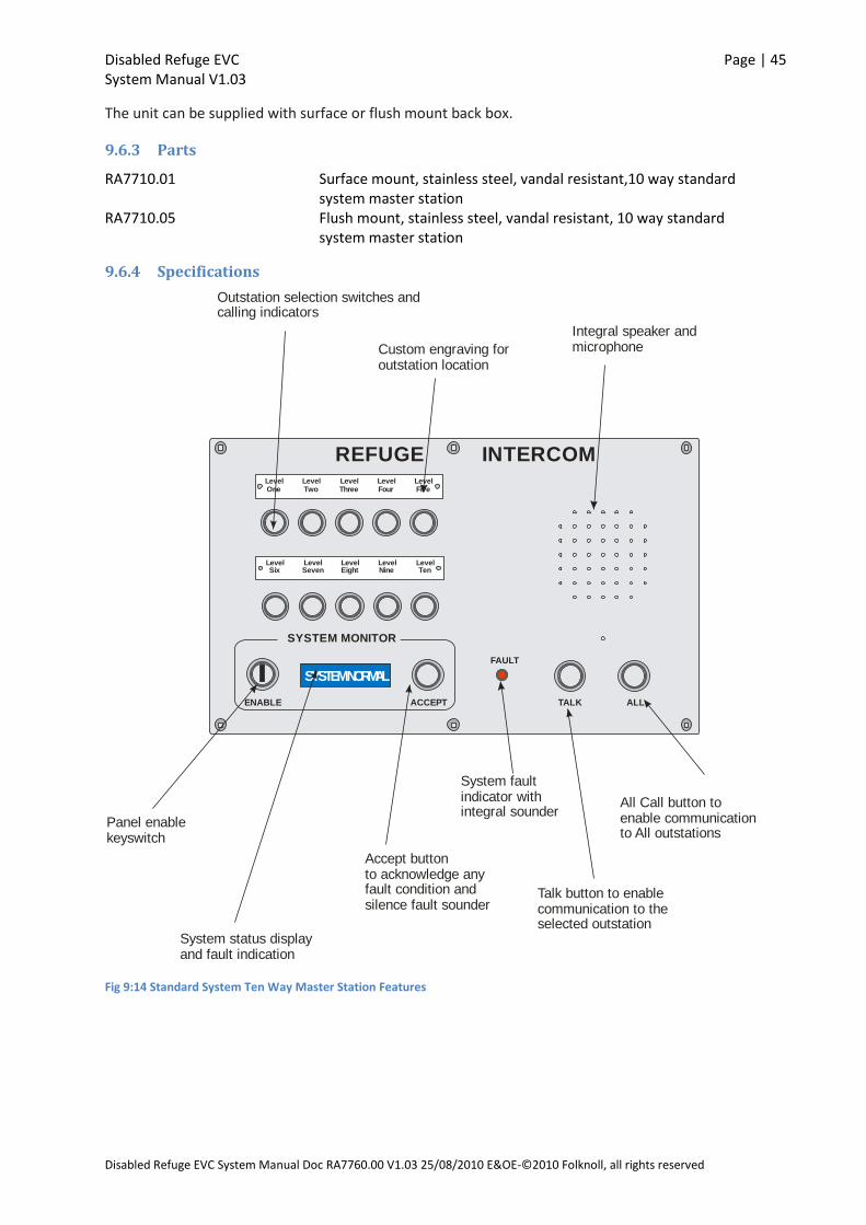
Disabled Refuge EVC Page | 45 System Manual V1.03
Disabled Refuge EVC System Manual Doc RA7760.00 V1.03 25/08/2010 E&OE-©2010 Folknoll, all rights reserved
The unit can be supplied with surface or flush mount back box.
9.6.3 Parts
RA7710.01 Surface mount, stainless steel, vandal resistant,10 way standard system master station
RA7710.05 Flush mount, stainless steel, vandal resistant, 10 way standard system master station
9.6.4 Specifications
LevelOne
LevelTwo
LevelThree
LevelFour
LevelFive
LevelSix
LevelSeven
LevelEight
LevelNine
LevelTen
FAULT
ACCEPTENABLE
SYSTEM NORMAL
SYSTEM MONITOR
TALK ALL
REFUGE INTERCOM
Talk button to enablecommunication to theselected outstation
All Call button toenable communicationto All outstations
System faultindicator withintegral sounder
Accept buttonto acknowledge anyfault condition andsilence fault sounder
Panel enablekeyswitch
System status displayand fault indication
Outstation selection switches andcalling indicators
Custom engraving foroutstation location
Integral speaker andmicrophone
Fig 9:14 Standard System Ten Way Master Station Features
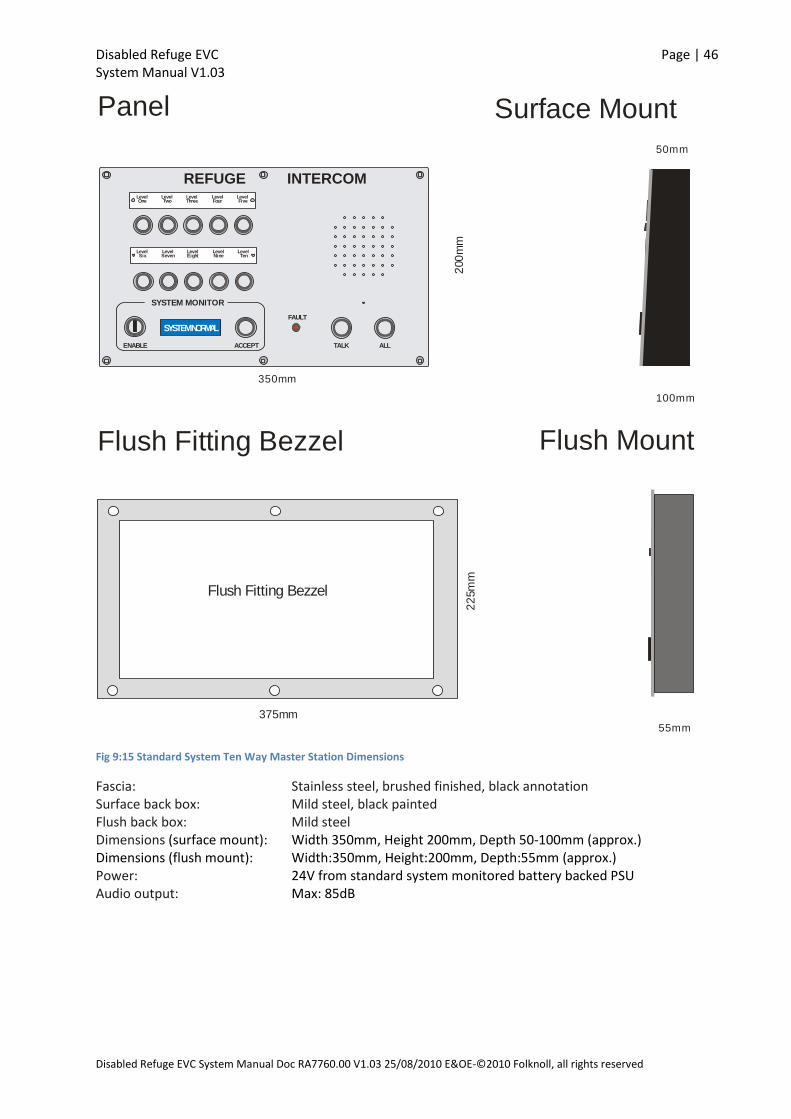
Disabled Refuge EVC Page | 46 System Manual V1.03
Disabled Refuge EVC System Manual Doc RA7760.00 V1.03 25/08/2010 E&OE-©2010 Folknoll, all rights reserved
350mm
200
mm
375mm
22
5m
m
Flush Fitting Bezzel
Panel
Flush Fitting Bezzel
Surface Mount
Flush Mount
55mm
100mm
50mm
LevelOne
LevelTwo
LevelThree
LevelFour
LevelFive
LevelSix
LevelSeven
LevelEight
LevelNine
LevelTen
FAULT
ACCEPTENABLE
SYSTEM NORMAL
SYSTEM MONITOR
TALK ALL
REFUGE INTERCOM
Fig 9:15 Standard System Ten Way Master Station Dimensions
Fascia: Stainless steel, brushed finished, black annotation Surface back box: Mild steel, black painted Flush back box: Mild steel Dimensions (surface mount): Width 350mm, Height 200mm, Depth 50-100mm (approx.) Dimensions (flush mount): Width:350mm, Height:200mm, Depth:55mm (approx.) Power: 24V from standard system monitored battery backed PSU Audio output: Max: 85dB

Disabled Refuge EVC Page | 47 System Manual V1.03
Disabled Refuge EVC System Manual Doc RA7760.00 V1.03 25/08/2010 E&OE-©2010 Folknoll, all rights reserved
9.6.5 Connections
StandardMaster Station
2 3 4 51 6
LOOP THROUGHDATA TERMINAL
Fig 9:16 Standard Master Station Connections
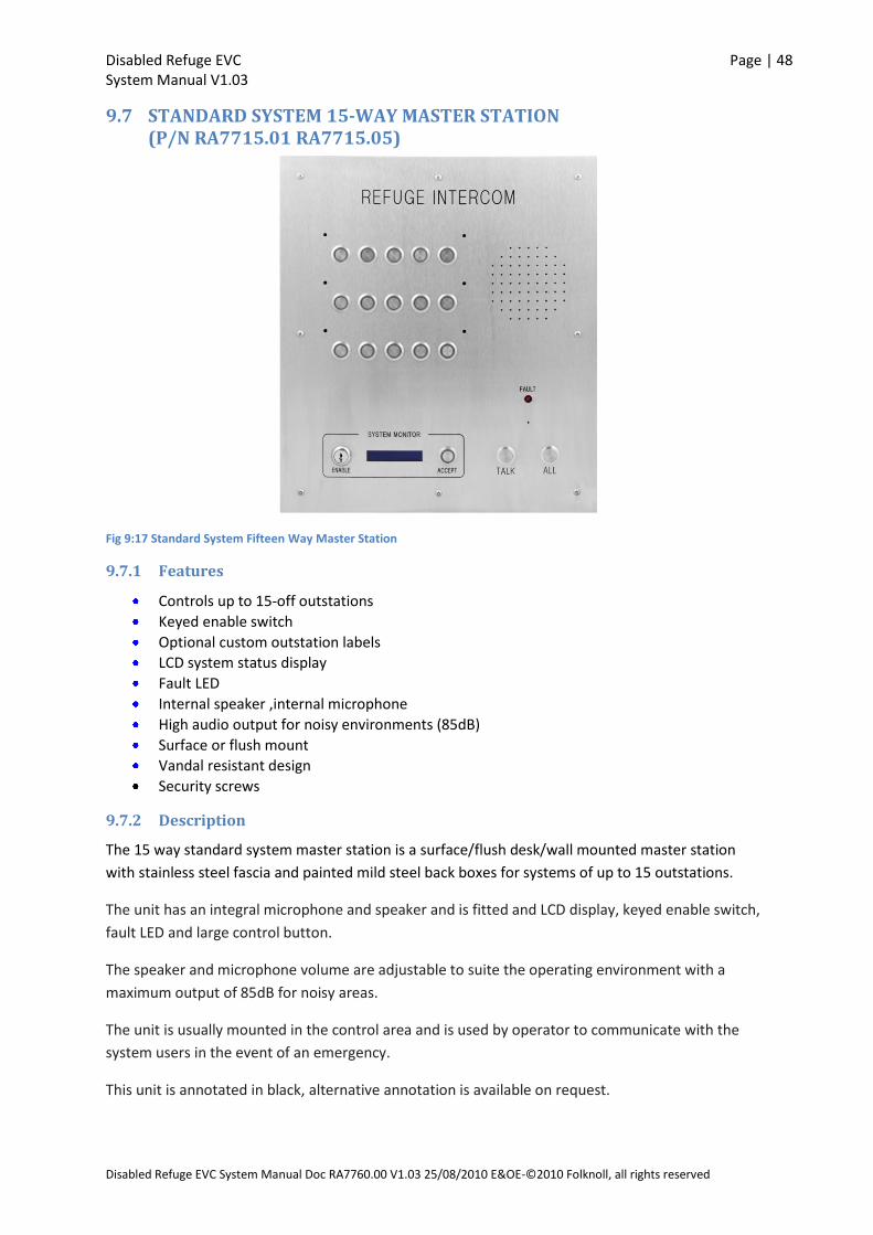
Disabled Refuge EVC Page | 48 System Manual V1.03
Disabled Refuge EVC System Manual Doc RA7760.00 V1.03 25/08/2010 E&OE-©2010 Folknoll, all rights reserved
9.7 STANDARD SYSTEM 15-WAY MASTER STATION (P/N RA7715.01 RA7715.05)
Fig 9:17 Standard System Fifteen Way Master Station
9.7.1 Features
Controls up to 15-off outstations
Keyed enable switch
Optional custom outstation labels
LCD system status display
Fault LED
Internal speaker ,internal microphone
High audio output for noisy environments (85dB)
Surface or flush mount
Vandal resistant design
Security screws
9.7.2 Description
The 15 way standard system master station is a surface/flush desk/wall mounted master station
with stainless steel fascia and painted mild steel back boxes for systems of up to 15 outstations.
The unit has an integral microphone and speaker and is fitted and LCD display, keyed enable switch,
fault LED and large control button.
The speaker and microphone volume are adjustable to suite the operating environment with a
maximum output of 85dB for noisy areas.
The unit is usually mounted in the control area and is used by operator to communicate with the
system users in the event of an emergency.
This unit is annotated in black, alternative annotation is available on request.
Disabled Refuge EVC Page | 49 System Manual V1.03
Disabled Refuge EVC System Manual Doc RA7760.00 V1.03 25/08/2010 E&OE-©2010 Folknoll, all rights reserved
The unit is supplied with a flush mount back box which can fitted into a black painted wood surround
for use on a console.
9.7.3 Parts
RA7715.01 Surface mount, stainless steel, vandal resistant,15 way standard system master station
RA7715.05 Flush mount, stainless steel, vandal resistant, 15 way standard system master station

Disabled Refuge EVC Page | 50 System Manual V1.03
Disabled Refuge EVC System Manual Doc RA7760.00 V1.03 25/08/2010 E&OE-©2010 Folknoll, all rights reserved
9.7.4 Specifications
L e v e lO n e
N o r th
L e v e lTw o
N o r th
L e v e lT h r e e
N o r th
L e v e lF o u r
N o r th
L e v e lF i v e
N o r th
L e v e lO n e
S o u th
L e v e lO n e
W e s t
L e v e lTw o
S o u th
L e v e lTw o
W e s t
L e v e lT h r e e
S o u th
L e v e lT h r e eW e s t
L e v e lF o u r
S o u th
L e v e lF o u rW e s t
L e v e lF i v e
S o u th
L e v e lF i v eW e s t
FAULT
ACCEPTENABLE
SYSTEM NORMAL
SYSTEM MONITOR
TALK ALL
REFUGE INTERCOM
Talk button to enablecommunication to theselected outstation
All Call button toenable communicationto All outstations
System faultindicator with
integral sounder
Accept buttonto acknowledge anyfault condition andsilence fault sounder
Panel enablekeyswitch
System status displayand fault indication
Outstation selection switches andcalling indicators
Integral speaker andmicrophone
Fig 9:18 Standard System Fifteen Way Master Station Features
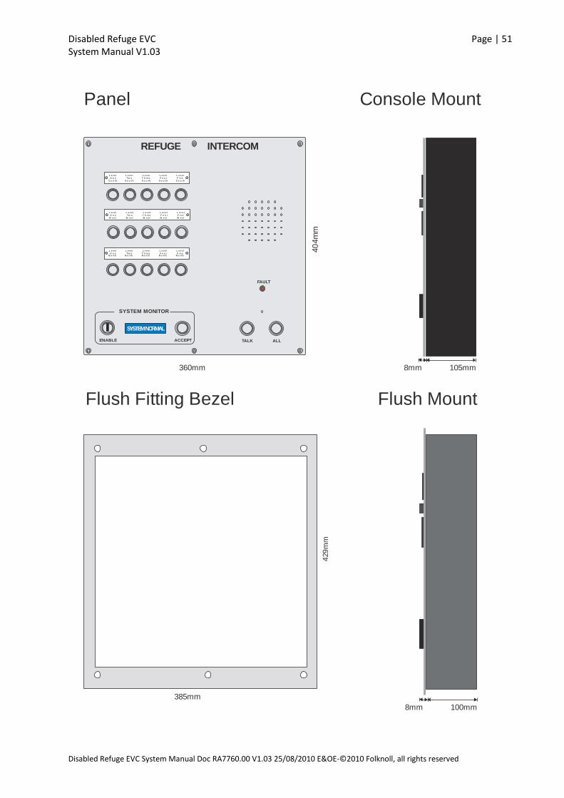
Disabled Refuge EVC Page | 51 System Manual V1.03
Disabled Refuge EVC System Manual Doc RA7760.00 V1.03 25/08/2010 E&OE-©2010 Folknoll, all rights reserved
L e v e l
O n eN o rt h
L e v e l
Tw oN o rt h
L e v e l
T h re eN o rt h
L e v e l
F o u rN o rt h
L e v e l
F i v eN o rt h
L e v e l
O n e
S o u t h
L e v e l
O n e
W e s t
L e v e l
Tw o
S o u t h
L e v e l
Tw o
W e s t
L e v e l
T h re e
S o u t h
L e v e l
T h re e
W e s t
L e v e l
F o u r
S o u t h
L e v e l
F o u r
W e s t
L e v e l
F i v e
S o u t h
L e v e l
F i v e
W e s t
FAULT
ACCEPTENABLE
SYSTEM NORMAL
SYSTEM MONITOR
TALK ALL
REFUGE INTERCOM
360mm
40
4m
m
375mm
429
mm
385mm
Flush Fitting Bezel
Panel Console Mount
Flush Mount
105mm8mm
100mm8mm

Disabled Refuge EVC Page | 52 System Manual V1.03
Disabled Refuge EVC System Manual Doc RA7760.00 V1.03 25/08/2010 E&OE-©2010 Folknoll, all rights reserved
Fig 9:19 Standard System Fifteen Way Master Station Dimensions
Fascia: Stainless steel, brushed finished, black annotation Console mount: Wood surround, black painted, mild steel flush back box insert. Flush back box: Mild steel. Dimensions (console mount): Width 360mm, Height 404mm, Depth 113mm (approx.) Dimensions (flush mount): Width 360mm, Height 404mm, Depth 108mm (approx.) Power: 24V from standard system monitored battery backed PSU Audio output: Max: 85dB
9.7.5 Connections
StandardMaster Station
2 3 4 51 6
LOOP THROUGHDATA TERMINAL
Fig 9:20 Standard Master Station Connections
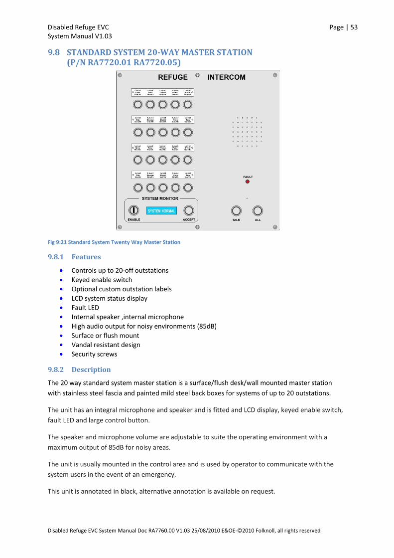
Disabled Refuge EVC Page | 53 System Manual V1.03
Disabled Refuge EVC System Manual Doc RA7760.00 V1.03 25/08/2010 E&OE-©2010 Folknoll, all rights reserved
9.8 STANDARD SYSTEM 20-WAY MASTER STATION (P/N RA7720.01 RA7720.05)
Fig 9:21 Standard System Twenty Way Master Station
9.8.1 Features
Controls up to 20-off outstations
Keyed enable switch
Optional custom outstation labels
LCD system status display
Fault LED
Internal speaker ,internal microphone
High audio output for noisy environments (85dB)
Surface or flush mount
Vandal resistant design
Security screws
9.8.2 Description
The 20 way standard system master station is a surface/flush desk/wall mounted master station
with stainless steel fascia and painted mild steel back boxes for systems of up to 20 outstations.
The unit has an integral microphone and speaker and is fitted and LCD display, keyed enable switch,
fault LED and large control button.
The speaker and microphone volume are adjustable to suite the operating environment with a
maximum output of 85dB for noisy areas.
The unit is usually mounted in the control area and is used by operator to communicate with the
system users in the event of an emergency.
This unit is annotated in black, alternative annotation is available on request.
Disabled Refuge EVC Page | 54 System Manual V1.03
Disabled Refuge EVC System Manual Doc RA7760.00 V1.03 25/08/2010 E&OE-©2010 Folknoll, all rights reserved
The unit is supplied with a flush mount back box which can fitted into a black painted wood surround
for use on a console.
9.8.3 Parts
RA7720.01 Surface mount, stainless steel, vandal resistant,20 way standard system master station
RA7720.05 Flush mount, stainless steel, vandal resistant,20 way standard system master station

Disabled Refuge EVC Page | 55 System Manual V1.03
Disabled Refuge EVC System Manual Doc RA7760.00 V1.03 25/08/2010 E&OE-©2010 Folknoll, all rights reserved
9.8.4 Specifications
Le v e lOne
North
Le v e lTwo
North
Le v e lThre eNorth
Le v e lFour
North
Le v e lFiv e
North
L e v e lO n e
S o u t h
L e v e lTw o
S o u t h
L e v e lT h re eS o u t h
L e v e lF o u r
S o u t h
L e v e lF iv e
S o u t h
Le v e lS ix
North
Le v e lS ix
S outh
Le v e lS e v e nNorth
Le v e lS e v e nS outh
Le v e lE ightNorth
Le v e lE ightS outh
Le v e lN ine
North
Le v e lN ine
S outh
Le v e lTe n
North
Le v e lTe n
S outh
FAULT
ACCEPTENABLE
SYSTEM NORMAL
SYSTEM MONITOR
TALK ALL
REFUGE INTERCOM
Talk button to enablecommunication to theselected outstation
All Call button toenable communicationto All outstations
System faultindicator with
integral sounder
Accept buttonto acknowledge anyfault condition andsilence fault sounder
Panel enablekeyswitch
System status displayand fault indication
Outstation selection switches andcalling indicators
Integral speaker andmicrophone
Fig 9:22 Standard System Twenty Way Master Station Features
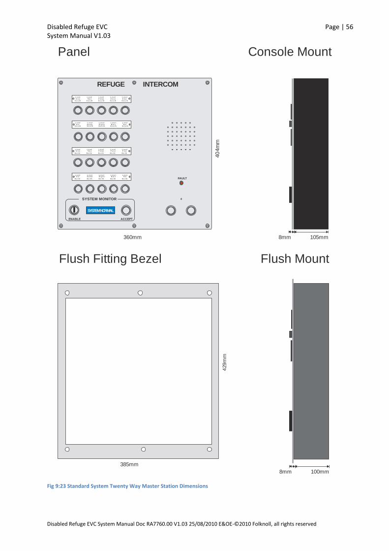
Disabled Refuge EVC Page | 56 System Manual V1.03
Disabled Refuge EVC System Manual Doc RA7760.00 V1.03 25/08/2010 E&OE-©2010 Folknoll, all rights reserved
105mm
L e v e lO n e
N o rt h
L e v e lTw o
N o rt h
L e v e lT h re e
N o rt h
L e v e lF o u r
N o rt h
L e v e lF i v e
N o rt h
L e v e l
O n e
S o u t h
L e v e l
Tw o
S o u t h
L e v e l
T h re e
S o u t h
L e v e l
F o u r
S o u t h
L e v e l
F i v e
S o u t h
L e v e lS i x
N o rt h
L e v e l
S i xS o u t h
L e v e lS e v e n
N o rt h
L e v e l
S e v e nS o u t h
L e v e lE i g h t
N o rt h
L e v e l
E i g h tS o u t h
L e v e lN i n e
N o rt h
L e v e l
N i n eS o u t h
L e v e lTe n
N o rt h
L e v e l
Te nS o u t h
FAULT
ACCEPTENABLE
SYSTEM NORMAL
SYSTEM MONITOR
REFUGE INTERCOM
360mm
40
4m
m
375mm
429
mm
385mm
Flush Fitting Bezel
Panel Console Mount
Flush Mount
100mm8mm
8mm
Fig 9:23 Standard System Twenty Way Master Station Dimensions
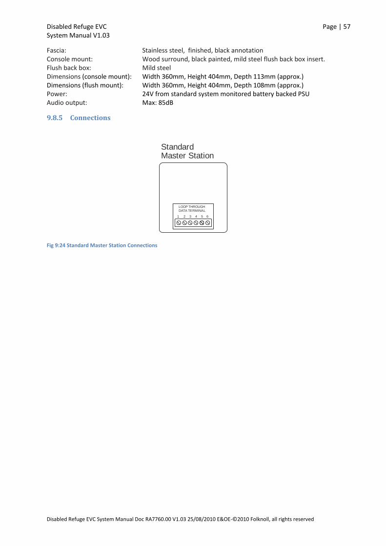
Disabled Refuge EVC Page | 57 System Manual V1.03
Disabled Refuge EVC System Manual Doc RA7760.00 V1.03 25/08/2010 E&OE-©2010 Folknoll, all rights reserved
Fascia: Stainless steel, finished, black annotation Console mount: Wood surround, black painted, mild steel flush back box insert. Flush back box: Mild steel Dimensions (console mount): Width 360mm, Height 404mm, Depth 113mm (approx.) Dimensions (flush mount): Width 360mm, Height 404mm, Depth 108mm (approx.) Power: 24V from standard system monitored battery backed PSU Audio output: Max: 85dB
9.8.5 Connections
StandardMaster Station
2 3 4 51 6
LOOP THROUGHDATA TERMINAL
Fig 9:24 Standard Master Station Connections
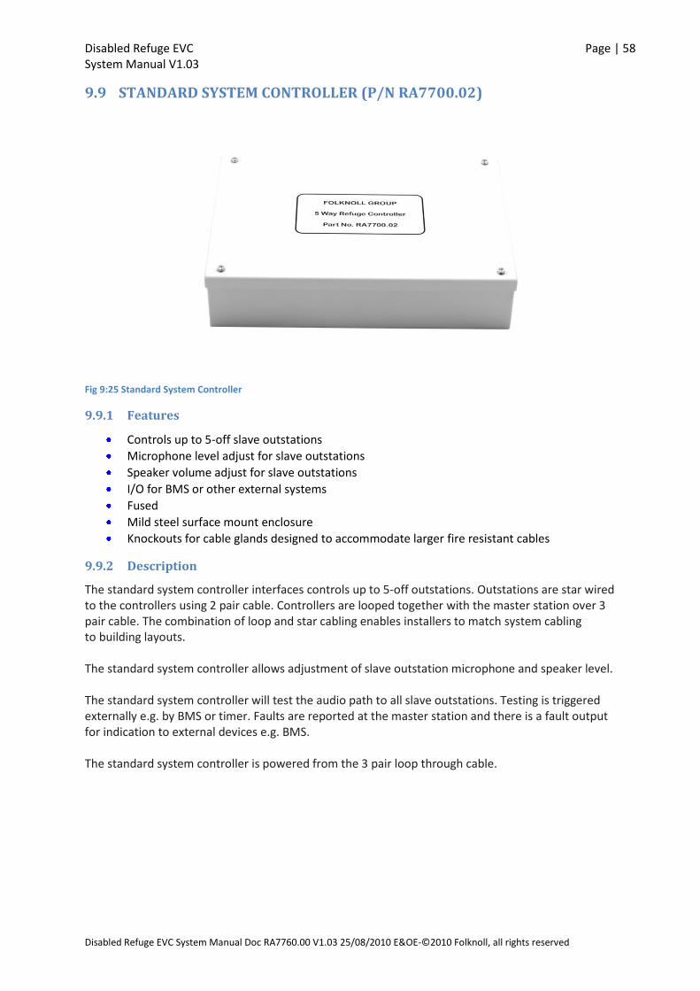
Disabled Refuge EVC Page | 58 System Manual V1.03
Disabled Refuge EVC System Manual Doc RA7760.00 V1.03 25/08/2010 E&OE-©2010 Folknoll, all rights reserved
9.9 STANDARD SYSTEM CONTROLLER (P/N RA7700.02)
Fig 9:25 Standard System Controller
9.9.1 Features
Controls up to 5-off slave outstations
Microphone level adjust for slave outstations
Speaker volume adjust for slave outstations
I/O for BMS or other external systems
Fused
Mild steel surface mount enclosure
Knockouts for cable glands designed to accommodate larger fire resistant cables
9.9.2 Description
The standard system controller interfaces controls up to 5-off outstations. Outstations are star wired to the controllers using 2 pair cable. Controllers are looped together with the master station over 3 pair cable. The combination of loop and star cabling enables installers to match system cabling to building layouts. The standard system controller allows adjustment of slave outstation microphone and speaker level. The standard system controller will test the audio path to all slave outstations. Testing is triggered externally e.g. by BMS or timer. Faults are reported at the master station and there is a fault output for indication to external devices e.g. BMS. The standard system controller is powered from the 3 pair loop through cable.

Disabled Refuge EVC Page | 59 System Manual V1.03
Disabled Refuge EVC System Manual Doc RA7760.00 V1.03 25/08/2010 E&OE-©2010 Folknoll, all rights reserved
9.9.3 Parts
RA7700.02 Surface mount, standard system controller
9.9.4 Specifications
Enclosure Mild steel Finish: White painted, Black annotation Mounting: Surface Dimensions (surface mount): Width 320mm, Height 220mm, Depth 72mm (approx.) Power: 24V from standard system monitored battery backed PSU Internal fuse: 2 amp Audio test input: Volt free System fault output: Closing contact (COM/NC/NO)
9.9.5 Connections
24V
EARTH
0V
SP
K -
MIC
+
MIC
-
SC
R
SP
K +
SP
K -
MIC
+
MIC
-
SC
R
SP
K +
SP
K -
MIC
+
MIC
-
SC
R
SP
K +
SP
K -
MIC
+
MIC
-
SC
R
SP
K +
SP
K -
MIC
+
MIC
-
SC
R
SP
K +
2
3
4
5
1
6
J10EARTHTERMINAL
J9LOOP THROUGHDATA TERMINAL
MON
J7POWERTERMINAL
OUTSTATION 1 OUTSTATION 2 OUTSTATION 3 OUTSTATION 4 OUTSTATION 5
Standard System Controller
Fig 9:26 Standard System Controller Connections

Disabled Refuge EVC Page | 60 System Manual V1.03
Disabled Refuge EVC System Manual Doc RA7760.00 V1.03 25/08/2010 E&OE-©2010 Folknoll, all rights reserved
J1
Su
b 1
(Outs
tatio
n 1
)
J5
Su
b 5
(Outs
tatio
n 5
)
J4
Su
b 4
(Outs
tatio
n 4
)
J3
Su
b 3
(Outs
tatio
n 3
)
J2
Su
b 2
(Outs
tatio
n 2
)
J7 (P
ow
er C
onn
ecto
r)
J9
(Maste
r Sta
tion
/Syste
m C
on
trolle
r Lo
op T
hro
ugh
Con
necto
r)
J10
Earth
J11
Syste
m T
est
(Short C
onn
ecto
r to T
rigg
er S
yste
m T
est)
J6
Fa
ult
(Syste
m T
est O
utp
ut)
Syste
m C
on
trolle
r PC
B
C1
2O
uts
tatio
n 1
Spea
ker
Volu
me
C8
Outs
tatio
n 1
Mic
ropho
ne
Volu
me
C12
AO
uts
tatio
n 2
Sp
eaker
Volu
me
C12
DO
uts
tatio
n 5
Sp
eaker
Volu
me
C12
CO
uts
tatio
n 4
Speaker
Volu
me
C12
BO
uts
tatio
n 3
Speaker
Volu
me
C8B
Ou
tsta
tion 3
Micro
phone
Volu
me
C8C
Outs
tatio
n 4
Mic
rophon
eV
olu
me
C8A
Outs
tatio
n 2
Micro
phon
eV
olu
me
C8D
Outs
tatio
n 5
Micro
phon
eV
olu
me
J8
6-1
0(‘A
ddre
ssin
g’)
J1
311-1
5(‘A
ddre
ssin
g’)
Fig 9:27 Standard System Controller PCB Layout

Disabled Refuge EVC Page | 61 System Manual V1.03
Disabled Refuge EVC System Manual Doc RA7760.00 V1.03 25/08/2010 E&OE-©2010 Folknoll, all rights reserved
9.10 STANDARD SYSTEM BATTERY BACKED PSU (P/N RA7750.02, RA7750.04)
Fig 9:28 Standard System Power Supply Unit
9.10.1 Features
Provides powers for standard Disabled Refuge EVC system with up to 20-off outstations.
Standby power
Houses battery set for standby power
Lockable, surface/wall mount, enclosure
Mains fail monitoring (reported by master station)
Local mains fail alarm, with silence button
Status LEDs
9.10.2 Description
The standard system monitored PSU is the standard Disabled Refuge EVC system power supply and
standby battery unit. The unit is usually mounted on a wall in an equipment room near to one of the
standard system controllers.
The PSU unit is supplied fully enclosed and ready for wall mounting. The unit is convection cooled
and should be mounted in a cool place with room for convection cooling to take place.
A single standard system monitored PSU will provide power for a complete Folknoll standard
Disabled Refuge EVC system of up to 20-off outstations.
When fitted with a standard system battery set the PSU will provide power for 24 hours standby and
30 minutes operation in the event of a main supply failure.
The unit enables the mains supply to be monitored by the Disabled Refuge EVC system. Mains failure
is reported by the master station.
The PSU unit has local mains fail alarm which can be silenced by means of a SILENCE button located
on the outside of the enclosure.

Disabled Refuge EVC Page | 62 System Manual V1.03
Disabled Refuge EVC System Manual Doc RA7760.00 V1.03 25/08/2010 E&OE-©2010 Folknoll, all rights reserved
9.10.3 Indicators
External Green LED – Supply healthy
External Yellow LED – Common fault (flashes if alarm sounder is silenced)
Internal Yellow LED - Battery fault
Internal Yellow LED - Mains fault
Internal Yellow LED – Volts fault
9.10.4 Parts
RA7750.02 Surface mount, standard system PSU RA7750.04 Standard system PSU battery set
9.10.5 Specifications
Enclosure: Mild steel (18 SWG) Finish: Metallic Silver (Radon MW334E) painted Mounting: Surface (5 holes in rear), 20m knockouts in top. Dimensions (surface mount): Width 400mm, Height 300mm, Depth 80mm (approx.) ROHS: Compliant lead free construction Power: 90V-264V ac, <2amps, 47-63Hz. Output: 19V d.c. min (battery) 30V d.c. max (mains) Fuse (Input): T3.1A 250 V a.c. Fuse (Load): 5A self setting Polyfuse Fuse (Battery Bypass): 6.3A (not replaceable)
9.10.6 Connections
Fig 9:29 Standard PSU Connections
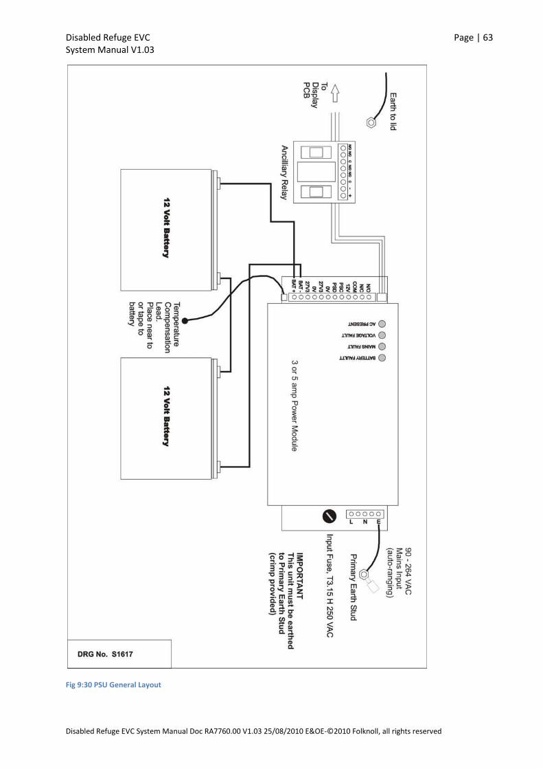
Disabled Refuge EVC Page | 63 System Manual V1.03
Disabled Refuge EVC System Manual Doc RA7760.00 V1.03 25/08/2010 E&OE-©2010 Folknoll, all rights reserved
Fig 9:30 PSU General Layout
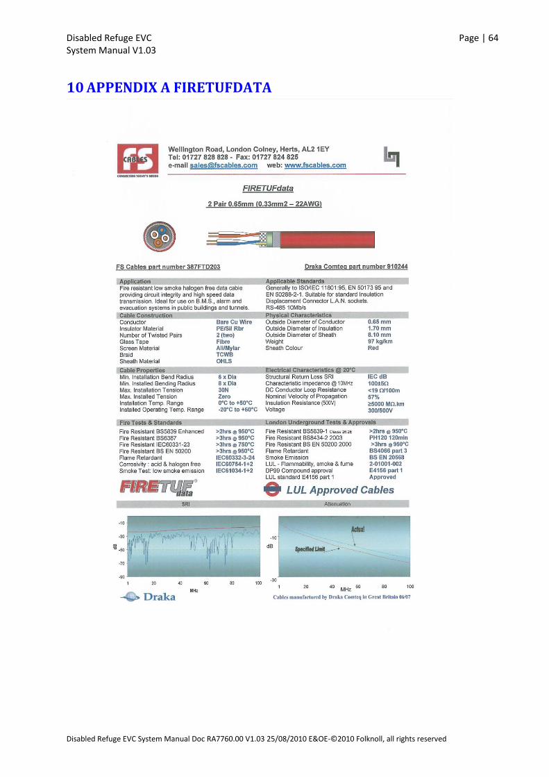
Disabled Refuge EVC Page | 64 System Manual V1.03
Disabled Refuge EVC System Manual Doc RA7760.00 V1.03 25/08/2010 E&OE-©2010 Folknoll, all rights reserved
10 APPENDIX A FIRETUFDATA
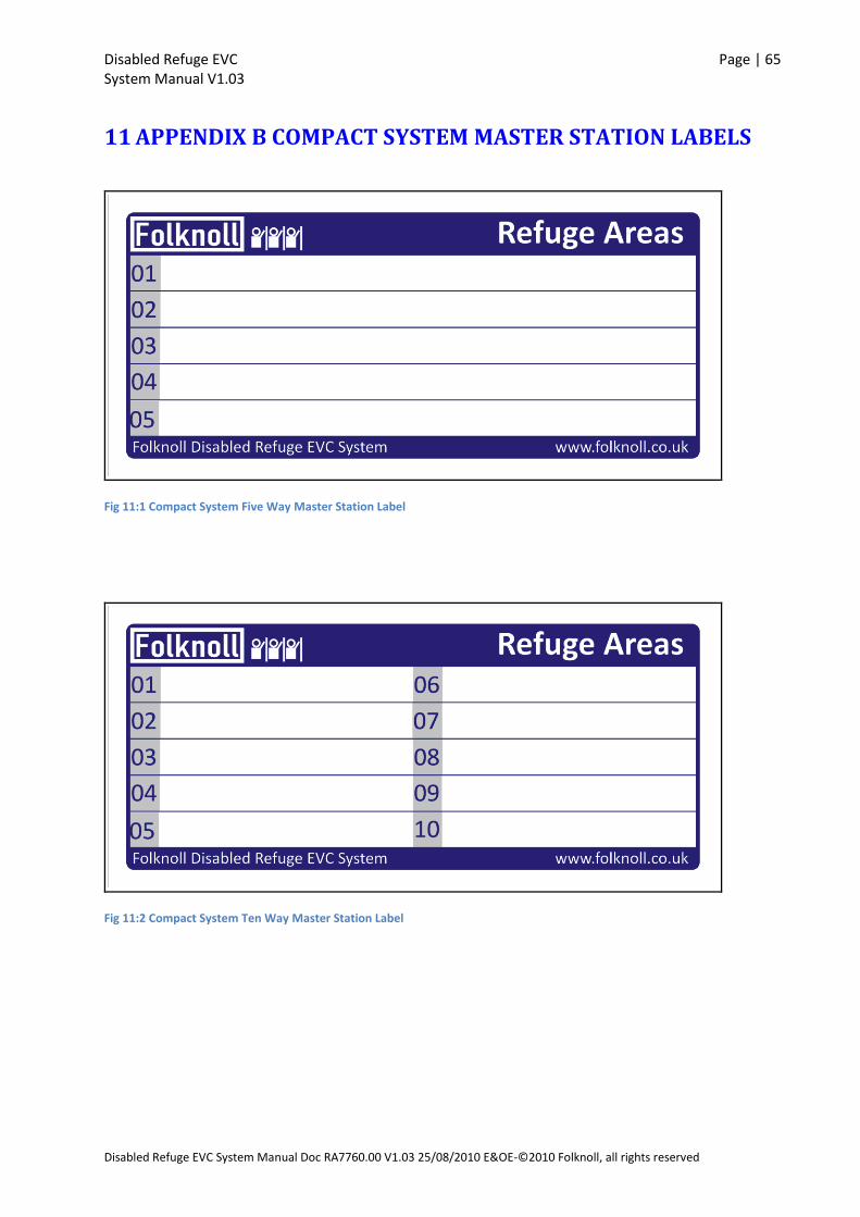
Disabled Refuge EVC Page | 65 System Manual V1.03
Disabled Refuge EVC System Manual Doc RA7760.00 V1.03 25/08/2010 E&OE-©2010 Folknoll, all rights reserved
11 APPENDIX B COMPACT SYSTEM MASTER STATION LABELS
Fig 11:1 Compact System Five Way Master Station Label
Fig 11:2 Compact System Ten Way Master Station Label
Disabled Refuge EVC Page | 66 System Manual V1.03
Disabled Refuge EVC System Manual Doc RA7760.00 V1.03 25/08/2010 E&OE-©2010 Folknoll, all rights reserved
12 USER NOTES This Section left blank for user notes.

Disabled Refuge EVC Page | 67 System Manual V1.03
Disabled Refuge EVC System Manual Doc RA7760.00 V1.03 25/08/2010 E&OE-©2010 Folknoll, all rights reserved

Folknoll
26 Old North Rd, Royston, HERTS, SG8 5DT Tel: 01763234567 [email protected] www.folknoll.co.uk