Digital Weight Indicator - Standard Scale & Supply · Agrifeed Model 5500 Digital Weight Indicator...
72
Agrifeed Model 5500 Digital Weight Indicator Reference Manual Issue AD
Transcript of Digital Weight Indicator - Standard Scale & Supply · Agrifeed Model 5500 Digital Weight Indicator...

Agrifeed Model 5500 Digital Weight Indicator
Reference Manual Issue AD
David Wright
Typewritten Text
Standard Scale & Supply Company 25421 Glendale Avenue Redford, MI 48239 313-255-6700 www.standardscale.com
David Wright
Typewritten Text
David Wright
Typewritten Text
David Wright
Typewritten Text
David Wright
Typewritten Text
David Wright
Typewritten Text
Preface We at GSE wish to thank you for selecting the Agrifeed 5500 Digital Weight Indicator for your weighing needs. The Agrifeed 5500 continues the GSE tradition of Excellence in Weighing Technology. When properly installed and maintained, the Agrifeed 5500 will provide many years of reliable, accurate performance. Please read the sections on installation and setup before proceeding with installation.
Warning The Agrifeed 5500 contains components which could be damaged by Electrostatic Discharge (ESD) if serviced improperly. Use proper ESD precautions (wear a wrist strap connected to ground, use grounded work stations, etc.) when opening the enclosure. ALWAYS unplug the Agrifeed 5500 when opening the enclosure. Installation and servicing of the Agrifeed 5500 should be performed by authorized and qualified service personnel only! It is important to ensure that the indicator stand is grounded to the truck frame or the truck battery. If the indicator stand cannot be secured directly to the truck frame, then it is necessary to provide a grounding strap from the stand to the frame. Failure to ground the stand can result in the buildup of a static charge that could damage electrical components within the indicator, thus voiding the warranty. The indicator power cable should be run directly to the positive and negative terminals of the battery. Proprietary Notice Information in this Reference Manual is subject to change without notice due to correction or enhancement. The information described in this manual is solely the property of GSE. This manual may not be distributed without written permission of GSE.
This manual is published by:
GSE
1525 Fairlane Circle Allen Park, MI 48101
http://www.gse-inc.com/ Phone: (313) 253-1300 Fax: (313) 253 - 1301
David Wright
Typewritten Text

i
Table of Contents
SECTION 1: INTRODUCTION ...................................................... 1 1.1 USING THIS MANUAL ................................................................ 1 1.2 OPERATOR INTERFACE .............................................................. 2 1.3 WEIGH MODE OPERATION ........................................................ 2 1.4 KEYPAD .................................................................................... 3 1.5 STANDARD FUNCTIONS ............................................................. 4 1.6 WARRANTY ............................................................................... 4 1.7 SPECIFICATIONS ........................................................................ 5
SECTION 2: INSTALLATION ........................................................ 7 2.1 UNPACKING ............................................................................... 7 2.2 MOUNTING ................................................................................ 7
2.2.1 Environmental .................................................................. 7 2.2.2 Rear Panel Mounting ........................................................ 7 2.2.3 Swivel Mounting (Optional) ............................................. 8
2.3 LEGAL FOR TRADE .................................................................... 8 2.3.1 Physical Seal..................................................................... 8 2.3.2 Audit Trail ........................................................................ 9
2.4 WIRING ..................................................................................... 9 2.4.1 Load Cell Connection ..................................................... 10 2.4.2 Printer Port Connection ................................................. 10 2.4.3 Comm Port Connection .................................................. 10 2.4.4 Remote Key Connection .................................................. 11 2.4.5 Power Connection .......................................................... 11 2.4.6 Alarm Out Connection .................................................... 12
SECTION 3: CONFIGURATION ................................................. 13 3.1 PASSWORD .............................................................................. 13
3.1.1 Entering a password ....................................................... 13 3.1.2 Changing the Default Password ..................................... 13
3.2 QUICK MENU .......................................................................... 14 3.3 SETUP MODE ........................................................................... 14
3.3.1 Print Setup ...................................................................... 15 3.3.2 Scale Setup ...................................................................... 16 3.3.3 Communication Setup ..................................................... 18 3.3.4 Memory Manager Setup ................................................. 23 3.3.5 Remote Display Setup ..................................................... 25 3.3.6 Ingredient Setup .............................................................. 26 3.3.7 Calibrate Mode ............................................................... 31 3.3.8 Mix Timer ....................................................................... 40
ii
SECTION 4: RECIPE SETUP ........................................................ 41 4.1 ACCESSING THE RECIPE DATABASE ......................................... 41 4.2 ADDING A RECIPE .................................................................... 42
4.2.1 Recipe Pre-Alarm ............................................................ 43 4.2.2 Weight Entry Method ...................................................... 44 4.2.3 Ingredient Selection ........................................................ 45
4.3 EDITING A RECIPE .................................................................... 46 4.4 DELETING A RECIPE ................................................................. 46 4.5 PRINTING RECIPES ................................................................... 47
SECTION 5: LOAD / UNLOAD OPERATION ............................ 49 5.1 LOADING INGREDIENTS ........................................................... 49
5.1.1 Selecting Individual Ingredients...................................... 49 5.1.2 Selecting a Recipe ........................................................... 49 5.1.3 Loading Process .............................................................. 50 5.1.4 Advancing Ingredients .................................................... 51
5.2 UNLOADING RECIPES ............................................................... 51 5.2.1 Selecting Individual Pens ................................................ 51 5.2.2 Selecting Pens from a List ............................................... 52 5.2.3 Unload Process ............................................................... 52 5.2.4 Advancing Pens ............................................................... 53 5.2.5 Unloading using Weight / Animal ................................... 53 5.2.6 Unfinished Load / Unload ............................................... 53
SECTION 6: TROUBLESHOOTING ........................................... 55 6.1 OPERATIONAL MODE ERROR MESSAGES ................................. 55 6.2 HARDWARE PROBLEM ERROR MESSAGES ............................... 56
6.2.1 Reload Agrifeed 5500 Custom Program ......................... 57 6.3 CALIBRATION ERROR MESSAGES ............................................ 58 6.4 COMMUNICATION ERROR MESSAGES ...................................... 59
6.4.1 Data Transmissions ......................................................... 59 6.4.2 Displayed Weight ............................................................ 59
6.5 A/D CALIBRATION PROCEDURE ............................................... 60 SECTION 7: AGRIFEED 5500 OPTION KITS ........................... 61
7.1 PERIPHERAL OPTIONS FOR THE AGRIFEED 5500 ...................... 61 7.1.1 Swivel Bracket Installation ............................................. 62 7.1.2 Remote Display Option ................................................... 63 7.1.3 Agridata Recipe Management Software .......................... 65 7.1.4 RF Remote Key................................................................ 65 7.1.5 RF Link............................................................................ 65
1
Section 1: Introduction
1.1 Using this Manual The manual is divided into sections that cover the major features of the indicator. Each section is then subdivided into smaller reference sections to provide details of each topic. Where applicable, references will be made to other sections that contain information pertinent to the current topic. Section Topic Discussion
1 Introduction Provides an introduction to the Agrifeed 5500 and its basic operation.
2 Installation Instructs how to get the Agrifeed 5500 operating quickly, correctly and safely.
3 Configuration Instructs how to access the Setup Mode and configure the indicator to a specific application.
4 Recipe Setup Instructs how to create and edit the recipe database.
5 Load/Unload Operation Demonstrates how to load and unload recipes.
6 Trouble-shooting Provides troubleshooting help and information on error messages.
7 Options Describes installation of the Agrifeed 5500 options.
Conventions Used In This Manual The GSE Agrifeed 5500 Digital Weight Indicator, hereafter referred to as the Agrifeed 5500, is capable of displaying alpha characters in either upper or lower case. For ease of reading, this manual uses conventional capitalization when referencing Agrifeed 5500 prompts. See Table 1 for the conventions used in this manual. Table 1: Typographical Conventions
[ZERO] A keypress appears in bold type with brackets.
200 [ZERO] Numeric entries preceding a keypress are also bold.
[CLR]+[ZERO] Keys separated with a ‘+’ must be pressed simultaneously.
“KeyIn CalWt” Display prompts are bold italic.
2
1.2 Operator Interface The Agrifeed 5500 makes extensive use of the display and keypad. The display and keypad perform different functions in the weigh mode, setup mode and help mode.
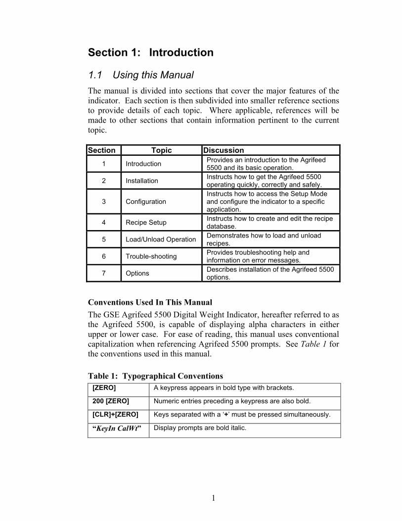
Upon power-up, the back-light and all pixels illuminate momentarily for a display test. The indicator then displays the Agrifeed GSE Model 5500 revision screen followed by the Operator ID? prompt (see Figure 1). Key in the operator ID number and press [ENTER], or press only [ENTER] to bypass the prompt. The operator ID will be recorded with each load or unload transaction saved in the history database.
Operator ID?
Key in ID# and press [ENTER], orPress [ENTER] to bypass.
Figure 1: Operator ID Entry
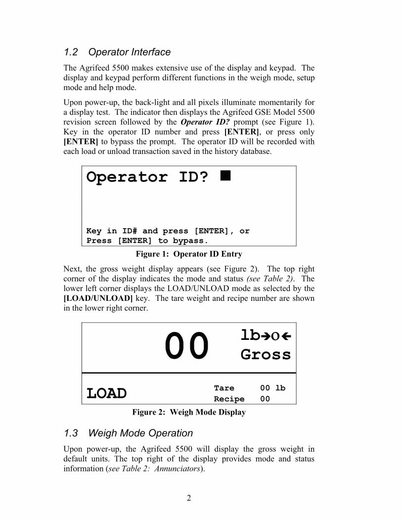
Next, the gross weight display appears (see Figure 2). The top right corner of the display indicates the mode and status (see Table 2). The lower left corner displays the LOAD/UNLOAD mode as selected by the [LOAD/UNLOAD] key. The tare weight and recipe number are shown in the lower right corner.
00 lb ο
Gross
LOAD Tare 00 lb Recipe 00
Figure 2: Weigh Mode Display
1.3 Weigh Mode Operation Upon power-up, the Agrifeed 5500 will display the gross weight in default units. The top right of the display provides mode and status information (see Table 2: Annunciators).

3
Table 2: Annunciators Annunciator Indication When Illuminated
→0← Displayed weight is at center-of-zero (± ¼ display graduation). Gross The displayed value represents the current gross weight.
Net The displayed value represents the current net weight. lb The displayed value is represented in pounds. kg The displayed value is represented in kilograms.
Tons The displayed value is represented in tons.
1.4 Keypad The Agrifeed 5500 keypad provides the following primary functions:
[ON] Turns indicator on
[OFF] Turns indicator off
[LOAD/UNLOAD] Toggles between the load and unload process
[MIX TIMER] Initiates the mix timer function
[SELECT INGRED] Scrolls ingredients during the load process
[TARE] Tares the displayed weight and selects the net mode
[NET/GROSS] Toggles the display mode between GROSS and NET
[ZERO] Zeros the scale if pressed immediately after the [NET/GROSS] key
[PRINT] Initiates data transmission out the printer port
[ENTER/YES] Answers ‘YES’ to prompts or completes operator entries. Displays time & date in weigh mode
[ADD RECIPE] Adds a new recipe to the recipe database using the first unused recipe number
[EDIT RECIPE] Invokes the edit routine for the currently selected recipe
[SELECT RECIPE] Sets the current recipe number
[START BATCH] Used to initiate the [LOAD/UNLOAD] process
[STOP BATCH] Used to stop/abort the [LOAD/UNLOAD] process
[HELP] Used to display information about various keys and access setup parameters
[CLR\NO] Answers “NO” to prompts. Also used to clear an entry

4
1.5 Standard Functions The Agrifeed 5500 includes several built-in functions that can be enabled through the indicator setup. These functions include the following:
• Remote key operation • Selectable data transmission formats • Mix Timer • Storage for 100 recipes • Storage for 100 ingredients
Refer to Section 3.3 on page 14 for setup and operation of these features.
1.6 Warranty Your Agrifeed 5500 is warranted against defects in materials and manufacturing for a period of two years from the date of purchase. In the event of a product failure due to materials or workmanship, GSE will, at its discretion, repair or replace the product. Always ensure proper installation and grounding. Never weld around the Agrifeed 5500 or load cells. Contact your GSE Agrifeed distributor for further details.
5
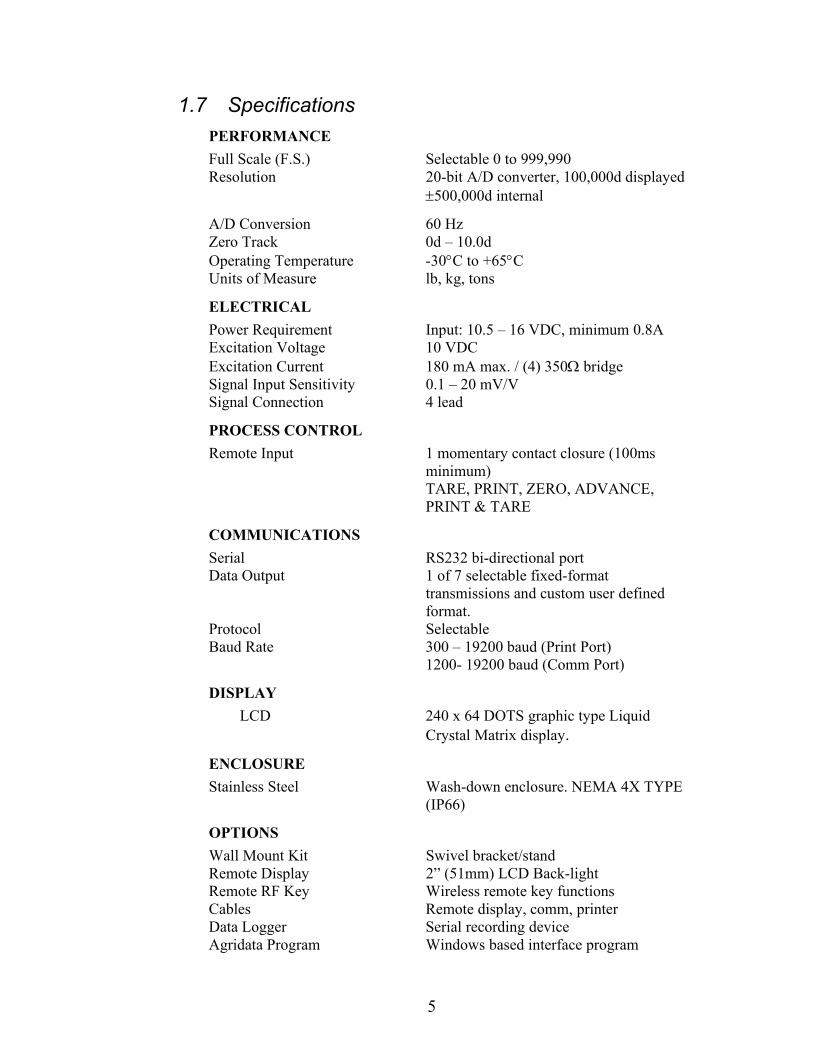
1.7 Specifications PERFORMANCE Full Scale (F.S.) Selectable 0 to 999,990 Resolution 20-bit A/D converter, 100,000d displayed
±500,000d internal
A/D Conversion 60 Hz Zero Track 0d – 10.0d Operating Temperature -30°C to +65°C Units of Measure lb, kg, tons
ELECTRICAL Power Requirement Input: 10.5 – 16 VDC, minimum 0.8A Excitation Voltage 10 VDC Excitation Current 180 mA max. / (4) 350Ω bridge Signal Input Sensitivity 0.1 – 20 mV/V Signal Connection 4 lead
PROCESS CONTROL Remote Input 1 momentary contact closure (100ms
minimum) TARE, PRINT, ZERO, ADVANCE, PRINT & TARE
COMMUNICATIONS Serial RS232 bi-directional port Data Output 1 of 7 selectable fixed-format
transmissions and custom user defined format.
Protocol Selectable Baud Rate 300 – 19200 baud (Print Port) 1200- 19200 baud (Comm Port)
DISPLAY LCD 240 x 64 DOTS graphic type Liquid
Crystal Matrix display.
ENCLOSURE Stainless Steel Wash-down enclosure. NEMA 4X TYPE
(IP66)
OPTIONS Wall Mount Kit Swivel bracket/stand Remote Display 2” (51mm) LCD Back-light Remote RF Key Wireless remote key functions Cables Remote display, comm, printer Data Logger Serial recording device Agridata Program Windows based interface program

6
This page is intentionally left blank

7
Section 2: Installation
2.1 Unpacking When unpacking your new Agrifeed 5500 Indicator, do not discard any packing material until you are sure you have all the components needed for your installation. Small bags are included containing parts that may be required for a complete installation.
2.2 Mounting This section contains information necessary for proper installation of the Agrifeed 5500. The standard enclosure is designed to allow wiring without opening the enclosure. All wiring is accessible through bottom connectors (see Figure 6: Agrifeed 5500 Connector Label).
2.2.1 Environmental The Agrifeed 5500 Stainless Steel enclosure is designed to NEMA 4X (IP66) type specifications.
2.2.2 Rear Panel Mounting The standard enclosure is designed to attach to an existing stand for mounting. Note that the stand shown in Figure 3 is not supplied by GSE.
Figure 3: Rear Panel Mounting Screws

8
2.2.3 Swivel Mounting (Optional) The optional swivel mounting bracket allows the enclosure to be securely fastened to another surface. The bracket is attached to the indicator with four thumbscrews two of which are used to lock the swivel for optimal viewing angle.
2.3 Legal for Trade Most legal-for-trade installations will require the Agrifeed 5500 to be sealed. A sealed indicator cannot be accessed for setup or calibration changes without breaking a physical seal or incrementing an event counter, thus providing evidence of tampering.
The Agrifeed 5500 has two types of sealing provisions, a physical seal and a three event audit trail counter. Check with your local weights and measures authority to determine your requirements.
2.3.1 Physical Seal The most common sealing method is a lead-wire seal. Before applying a wire seal, move the program jumper to the ‘NO’ position as shown in Figure 4. Doing this will prevent access to the Setup and Calibration Modes.
Figure 4: Program Jumper

9
The seal will pass through two back panel screws as shown in Figure 5.
Figure 5: Legal for Trade Sealing Method
2.3.2 Audit Trail Three separate incrementing, non-resetable audit trail parameters are used to indicate changes to various parameters, P60201 – OIML, P60203 – Calibration , and P60204 – Setup. An audit trail counter will increment only once upon exiting the Setup Mode and saving changes regardless of how many settings were changed.
With the indicator off, press and hold [CLR] key and turn power on. Continue to hold [CLR] until "Macro Disbl" is displayed. Key in "60203" and press [NET/GROSS] to view the calibration event counter, or key in "60204" and press [NET/GROSS] to view the configuration event counter. To return to the normal weigh mode from either parameter "60203" or "60204", press the [ZERO] key.
2.4 Wiring A description of all wiring terminals is included on the bottom label of the enclosure as shown in Figure 6.
Figure 6: Agrifeed 5500 Connector Label

10
2.4.1 Load Cell Connection A high quality cable with braided shield is recommended. Use a four-conductor, 16 to 24 AWG stranded wire cable for load cell or summing box connections.
2.4.2 Printer Port Connection The printer port is a RS232 bi-directional serial port that can be connected to a printer or computer. Use the custom print formats described in section 3.3.3 to configure the printer port output.
When making the printer port connections, consideration should be given to the communication protocol. Refer to Table 3 in order to determine proper wiring for the printer port.
Table 3: Printer Port Connections Pin Name Description 1 CTS Clear-to-Send 2 TXD Transmit3 RTS Request-to-Send4 RXD Receive 5 N/C -6 GND Digital Ground7 N/C - 8 N/C -
2.4.3 Comm Port Connection The Comm port is a RS232 bi-directional serial port that can be connected to a computer or any other serial device. This port can be used for bi-directional communications with a serial device, through an RF link or data logger, for recipe and transaction data exchange.
Before connecting to the comm port, consideration should be given to the communication protocol. To determine proper wiring to the comm port, refer to Table 4.
Table 4: Communication Port Connections Pin Name Description 1 CTS Clear-to-Send2 TXD Transmit 3 RTS Request-to-Send 4 RXD Receive 5 +5V + 5 Volts DC 6 GND Digital Ground7 N/C - 8 N/C -
11
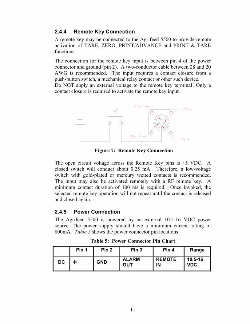
2.4.4 Remote Key Connection A remote key may be connected to the Agrifeed 5500 to provide remote activation of TARE, ZERO, PRINT/ADVANCE and PRINT & TARE functions.
The connection for the remote key input is between pin 4 of the power connector and ground (pin 2). A two-conductor cable between 28 and 20 AWG is recommended. The input requires a contact closure from a push-button switch, a mechanical relay contact or other such device. Do NOT apply an external voltage to the remote key terminal! Only a contact closure is required to activate the remote key input.
The open circuit voltage across the Remote Key pins is +5 VDC. A closed switch will conduct about 0.25 mA. Therefore, a low-voltage switch with gold-plated or mercury wetted contacts is recommended. The input may also be activated remotely with a RF remote key. A minimum contact duration of 100 ms is required. Once invoked, the selected remote key operation will not repeat until the contact is released and closed again.
2.4.5 Power Connection The Agrifeed 5500 is powered by an external 10.5-16 VDC power source. The power supply should have a minimum current rating of 800mA. Table 5 shows the power connector pin locations.
Table 5: Power Connector Pin Chart
Figure 7: Remote Key Connection
Pin 1 Pin 2 Pin 3 Pin 4 Range
DC + GND ALARM OUT
REMOTE IN
10.5-16 VDC

12
2.4.6 Alarm Out Connection This connection is used in conjunction with the [MIX TIMER] key. When the mix timer is not active pin 3 has a floating output. When the mix timer is active (i.e. counting down) pin 3 is pulled high to the supply voltage.
Example:
The indicator power is supplied by a truck battery, typically 13.8 volts. The output from pin 3 is 13.8 volts when the mix timer is active.
Figure 8: Alarm Out Connection
13
Section 3: Configuration
3.1 Password A password must be entered for full access to all setup parameters. The password routine may be bypassed by pressing [ENTER] without entering a password. Bypassing the password allows access to only Quick Menu items listed in section 3.2.
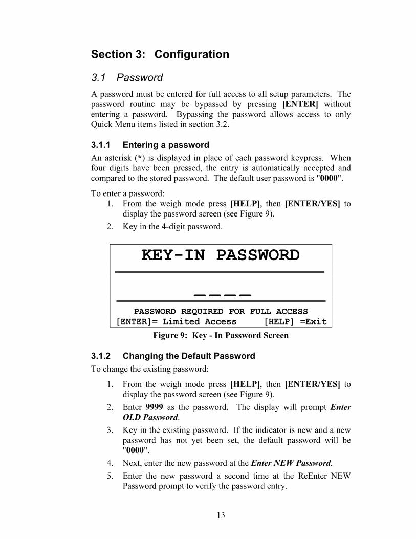
3.1.1 Entering a password An asterisk (*) is displayed in place of each password keypress. When four digits have been pressed, the entry is automatically accepted and compared to the stored password. The default user password is "0000".
To enter a password: 1. From the weigh mode press [HELP], then [ENTER/YES] to
display the password screen (see Figure 9). 2. Key in the 4-digit password.
KEY-IN PASSWORD
_ _ _ _
PASSWORD REQUIRED FOR FULL ACCESS [ENTER]= Limited Access [HELP] =Exit
Figure 9: Key - In Password Screen
3.1.2 Changing the Default Password To change the existing password:
1. From the weigh mode press [HELP], then [ENTER/YES] to display the password screen (see Figure 9).
2. Enter 9999 as the password. The display will prompt Enter OLD Password.
3. Key in the existing password. If the indicator is new and a new password has not yet been set, the default password will be "0000".
4. Next, enter the new password at the Enter NEW Password. 5. Enter the new password a second time at the ReEnter NEW
Password prompt to verify the password entry.

14
6. If the password entered in step 5 is correct, “New Password Saved!” is displayed briefly before returning to the weigh mode.
3.2 Quick Menu The Quick Menu provides access to data logger, display contrast, display back-light and remote display back-light settings. A password is not required to access the Quick Menu.
To access the Quick Menu: 1. From the weigh mode, press [HELP], then [ENTER]. 2. At the password prompt, press only the [ENTER] key.
To navigate Quick Menu:
1. Press [YES] to advance to the next parameter. 2. Press [NO] to select options within a parameter. 3. Press [HELP] to save changes and exit the Quick Menu.
3.3 Setup Mode The Setup Mode provides access to all setup parameters and calibration.
To access the Setup Mode: 1. Press [HELP], then [ENTER] as prompted in the Help screen. 2. Key in the 4-digit password to access the Setup Mode as shown
in Figure 9 (see section 3.1.1 for password information).
SETUP MENU SELECTION
SCALE SETUP
[YES]=Access [NO]=Next [HELP]=Exit
Figure 10: Setup Menu Selection Screen
To navigate the main category headings of the Setup Menu: 1. Press [NO] to advance to the next setup category (see Figure 11
for setup category headings). 2. Press [YES] to access setup parameters for the displayed
category. 3. Press [HELP] to save changes and exit the Setup Mode.

15
SCALE SETUP COMM SETUP MEMORY MANAGER REMOTE SETUP INGREDIENT SETUP CALIBRATION
Figure 11: Setup Category Headings
3.3.1 Print Setup A print setup may be done from the SCALE SETUP, COMM SETUP, MEMORY MANAGER, REMOTE SETUP and INGREDIENT SETUP. If the print key is pressed from any of these menus, the parameters within that menu will be printed. Below is an example of the MEMORY MANAGER SETUP print out:
MEMORY MANAGER SETUP PARAMETERS ------------------------------------------------------------ UNLOAD DATA LOGGER DATA LOGGER
ENABLED RECORD HISTORY 500 TOTAL HISTORY ROWS
2 ROWS USED 498 ROWS AVAILABLE
15:43 02/04/08 DATE HISTORY CLEARED
The SCALE SETUP, COMM SETUP, MEMORY MANAGER and REMOTE SETUP menus can all be printed from the quick menu. Simply press the print key after accessing the quick menu setup.

16
3.3.2 Scale Setup Access the Scale Setup as described in section 3.3. Table 6 describes the Scale Setup parameters.
SETUP MENU SELECTION
SCALE SETUP
[YES]=Access [NO]=Next [HELP]=Exit
Figure 12: Setup Menu Selection - Scale Setup
To navigate the Scale Setup selections: 1. Press [YES] to advance to the next parameter. 2. Press [NO] to select options within a parameter. 3. Press [HELP] to return to the Setup Menu Selection screen. 4. Press [HELP] again to save changes and exit the setup mode.
Example To change the PRE-ALARM METHOD:
1. From the SCALE SETUP screen, press [YES] 3 times. 2. Press [NO] to toggle between COMMON & RECIPE PRE-
ALARM. 3. Press [HELP] twice to save changes and exit the setup mode

17
Table 6: Scale Setup Menu Parameters
Parameter Description Selections LCD
CONTRAST SETUP
Sets the level of contrast (or darkness) of characters on the display.
0-100% in 5% intervals. *55%
LCD BACKLIGHT SETUP
Sets the display back-light brightness. 0-100% in 10% intervals. *50%
PRE-ALARM
METHOD
RECIPE PRE-ALARM: Pre-Alarm based on individual recipes/ingredients.
COMMON PRE-ALARM: Pre-Alarm based on the PRE-ALARM WEIGHT in setup.
*COMMON PRE-ALARM, and RECIPE PRE-ALARM
PRE-ALARM
WEIGHT
Sets the weight at which the alarm sounds prior to reaching the load/unload target weight. This parameter can only be set if the PRE-ALARM METHOD is set to COMMON PRE-ALARM. (see section 4.2.1 for more details)
Key in value: 0-999990 *00 lb
ADVANCE TOLERAN
CE
Sets the tolerance requirement for loading before auto-advancing ingredients.
*OFF, 0.5%, 1-10%
ADVANCE DELAY
Sets the time requirement for auto-advancing ingredients. The weight must be in tolerance and stable within the ADVANCE DELAY time before and auto-advance will occur.
1-5,10, 15, 30, 45 sec., 1, 2 min., *Manual
REMOTE INPUT
ACTION
Defines the remote key function. * PRINT/ADVANCE is the default
TARE, ZERO, PRINT & TARE, PRINT/ADVANCE
TIME&DA
TE Sets the time and date. Key in Time/Date
CAPACITY SETUP Sets the scale capacity.
Key in value: 0.02-999990 *40000 lb
DIVISON SIZE
Sets the scale division size (count by). If the capacity or division size is changed such that the number of divisions is not between 1 and 100000, then an appropriate division size is automatically selected.
.0001 to 500 *000010
ZERO TRACK
Sets the Zero Track Aperture. Weight deviations that remain within the Zero Track range for more than 1 second are tracked off (zeroed).
0.5, 1-5, 10 divisions, OFF *1.0

18
Parameter Description Selections
MOTION SETUP
Defines the amount of instability in terms of number of divisions that will constitute motion. Presence of motion will delay ZERO, TARE or ingredient Auto-Advance until motion ceases.
0.5, 1-5, 10 divisions, OFF *1.0
FILTER SETUP
Determines how quickly the indicator will respond to a change in weight. A low filter setting results in fast response, while a heavier filter setting will ‘dampen’ the response. Filtering is used to help stabilize weight fluctuations due to wind, vibration, etc.
MINIMUM, LOW, *MEDIUM, HEAVY, MAXIMUM
DISPLAY UPDATE
RATE
Sets the rate at which the weight display is refreshed.
5/sec, 2/sec, 1 sec, 2 sec *2/SEC
UNITS SETUP Sets the default weight units. lb, kg, Tons
*lb * indicates default setup
3.3.3 Communication Setup Access the Communication Setup as described in section 3.3. Table 7 describes the Communication Setup parameters.
SETUP MENU SELECTION
COMM SETUP
[YES]=Access [NO]=Next [HELP]=Exit
Figure 13: Setup Menu Selection - Comm Setup
To navigate the Communication Setup selections:
1. Press [YES] to advance to the next parameter. 2. Press [NO] to select options within a parameter. 3. Press [HELP] to return to the Setup Menu Selection screen. 4. Press [HELP] again to save changes and exit the setup mode.

19
Example: To enable the CUSTOM PRINT HEADER: 1. From the COMM SETUP screen, press [YES] twice. 2. Press [NO] to toggle between ENABLED and DISABLED 3. Press [HELP] twice to save changes and exit the setup mode.
Table 7: Communication Setup Parameters Parameter Description Selections
CUSTOM PRINT
HEADER
Enabled to print custom header on each ticket.
ENABLED,
*DISABLED
PRINT HEADER LINE
# (1 - 4)
Permits entry of a custom print header (up to 4 lines). This parameter can only be set if the CUSTOM PRINT HEADER is ENABLED.
Refer to section 3.3.3.1 for instructions on entering print headers.
CUSTOM PRINT
FORMAT
Sets unload print format. Choose from 7 pre- set formats or select “CUSTOM” format (contact your Agrifeed distributor for information on creating custom transmits).
Refer to section 3.3.3.2 for print styles.
Press [PRINT] to preview format
*STYLE #7
TICKET NUMBER Reset printed ticket number. Press [CLR\NO] then
key in value
AUTO PRINT Assigns an event for auto-printing.
* LOAD & UNLOAD, LOAD, UNLOAD, DISABLED
COMM BAUD RATE
Sets the baud rate for the comm port.
1200,2400,4800, 9600,*19200,38400 Baud
WAGON NUMBER
Sets truck or wagon ID number. Numbers 1-247 are valid wagon numbers for use with Agridata software. A wagon number of zero (000) will disable the RF link.
*000 Press [CLR\NO] then key in value
COMM PROTOCOL
Sets the protocol for the communication port. (data bits / parity / stop bits)
*8/NONE/1, 8/ODD/1, 8/EVEN/1, 8/NONE/2, 7/NONE/1, 7/ODD/1, 7/EVEN/1, 7/NONE/2

20
Parameter Description Selections
COMM HANDSHAKE
Sets handshaking for the communications port.
*XON/XOFF, BOTH, NONE, CTS/RTS
PRINT BAUD
RATE
Sets the baud rate for the printer port.
300,600,1200,2400,4800, *9600,19200 baud.
PROTOCOL
Sets the protocol for the printer port. (data bits / parity / stop bits)
*8/NONE/1, 8/ODD/1, 8/EVEN/1, 8/NONE/2, 7/NONE/1, 7/ODD/1,
PRINT HANDSHAKE
Sets the handshaking for the printer port.
*XON/XOFF, BOTH, NONE, CTS/RTS
* indicates default setup
3.3.3.1 Custom Print Headers 4 lines of up to 20 characters each may be assigned to the header. The CUSTOM PRINT HEADER parameter must be enabled before it is possible to assign text to the print header. To create or change a Custom Print Header:
1. Access the PRINT HEADER LINE #1 parameter as described in section 3.3.3.1.
2. Press [NO] to access the header entry screen (see Figure 14).
ENTER HEADER #1
ABCDEFGHIJKLMNOPQRSTUVWXYZ +-*/=#$()<>&@
Figure 14: Custom Header Entry Screen
3. Use the cursor keys to key in the header text. Use the numeric
portion of the keypad to enter numbers.

21
3.3.3.2 Print Styles There are seven selectable print styles and one custom print format available within the Agrifeed 5500.
1. Print style #1 prints the TICKET#, Time, Date, RECIPE#, PEN#, and amount of product loaded or unloaded.
2. Print style #2 prints the Time, Date, Pen ID number, Gross, Tare, and Net weights.
3. Print style #3 prints the Gross, Tare and Net weights. 4. Print style #4 prints the current Time, Date and Gross weight. 5. Print style #5 prints the TICKET #, Time, Date, PEN #,
RECIPE # and the amount of product loaded or unloaded in comma delimited format.
6. Print style #6 prints the current Time, Date, Pen ID number, and displayed weight.
7. Print style #7 prints the PEN #, Gross weight, Time and Date.
Moves left to
previous character
Moves right
to next character
Selects the
character under the cursor arrow
Enters header text and completes entry
Deletes the last character of the header text

22
Style #1 Style #2
Style #3 Style #4
Style #5
Style #6
Style #7
03:31 pm 04/04/07 ID#: 12345 ------------------ 2090 lb Gross 00 lb Tare 2090 lb Net
TICKET# 1234567 03:30 pm 04/04/07 RECIPE# 13 PEN# 12345 AMOUNT 2010 lb
2090 lb Gross 00 lb Tare 2090 lb Net
03:33 pm 04/04/07 2090 lb Gross
1234567,03:33 pm 04/04/07,12345,13,2010
Time 03:03 pm Date 04/04/07
Pen# 12345 016100 13:17 04/04/07

23
3.3.4 Memory Manager Setup Access the Memory Manager Setup as described in section 3.3. Table 8 describes the Memory Manager Setup parameters.
SETUP MENU SELECTION
MEMORY MANAGER
[YES]=Access [NO]=Next [HELP]=Exit
Figure 15: Setup Menu Selection - Memory Manager
To navigate the Memory Manager Setup selections:
1. Press [YES] to advance to the next parameter. 2. Press [NO] to select options within a parameter. 3. Press [HELP] to return to the Setup Menu Selection screen. 4. Press [HELP] again to save changes and exit the setup mode.
Example: To enable the RECORD HISTORY: 1. From the MEMORY MANAGER SETUP screen, press [YES] twice. 2. Press [NO] to toggle between ENABLED and DISABLED. 3. Press [HELP] twice to save changes and exit the setup mode.

24
Table 8: Memory Manager Setup Menu Parameters Parameter Description Selections
DATA LOGGER
Used to transfer recipe/pen information from the data logger to the Agrifeed 5500 (unload data logger), or to transfer history information to the data logger from the AGRIFFEED 5500 (load data logger). Press [LOAD/UNLOAD] to initiate data transfer routine.
UNLOAD DATA
LOGGER,
*LOAD DATA LOGGER
RECORD HISTORY
Used for managing the history database. WHEN THIS PARAMETER IS DISABLED, NO DATA WILL BE STORED TO THE HISTORY DATABASE!
ENABLED, DISABLED,
TOTAL
HISTORY ROWS
Shows the total history rows available for data storage. EXAMPLE:
500
ROWS USED
Shows the number of records that are stored in the history database. Also the database may be cleared from this selection. Press [CLR\NO] and follow the display prompts.
EXAMPLE: 182
ROWS
AVAILABLE
Shows the number of unused rows in the history database. EXAMPLE:
318
DATA HISTORY CLEARED
Shows the time and date the history database was last cleared. EXAMPLE:
04:56 pm 02/04/00
When the history is 90% full, the following warning will appear on the display:
MEMORY WARNING
THE HISTORY DATABASE IS 90% FULL!
Download the history database to avoid losing data once the database is full.
PRESS [ENTER] TO CONTINUE.
Additional warning screens will be displayed when the memory is 95% and 100% full. If the memory is not cleared, the oldest history data will

25
be lost as new information is recorded. Refer to the MEMORY MANAGER section to clear the history database.
3.3.5 Remote Display Setup Access the Remote Display Setup as described in section 3.3. Table 9 describes the Remote Display Setup parameters.
SETUP MENU SELECTION
REMOTE SETUP
[YES]=Access [NO]=Next [HELP]=Exit
Figure 16: Setup Menu Selection - Remote Setup
To navigate the Remote Setup selections:
1. Press [YES] to advance to the next parameter. 2. Press [NO] to select options within a parameter. 3. Press [HELP] to return to the Setup Menu Selection screen. 4. Press [HELP] again to save changes and exit the setup mode.
Table 9: Remote Display Setup Parameters Parameter Description Selections REMOTE
BACKLIGHT Enables the Model 1500 remote display back-light.
DISABLED, ENABLED
REMOTE MIRROR IMAGE
Enables the Model 1500 remote display reverse image feature allowing it to be viewed with a mirror. Select ‘UNLOAD ONLY’ to enable the mirror imaging only while unloading.
DISABLED, ENABLED, UNLOAD
ONLY
3.3.5.1 Remote Display Operation Upon power-up, the remote display shows ID ? indicating that the operator ID has not yet been entered.

26
During normal operation the remote display will echo the gross or net weight as displayed on the Agrifeed 5500. During the load/unload process the remote display will show the gross for two seconds between the change of ingredients or pens. It will then toggle between the name of the current ingredient or pen and the target net weight until motion occurs.
The [NET\GROSS] key may be pressed at any time during the load/unload process to display the gross weight for 2 seconds.
3.3.6 Ingredient Setup The Ingredient Setup Mode provides the ability to create, edit, delete and view ingredients. Access the Ingredient Setup as described in section 3.3.
Figure 17: Setup Menu Selection - Ingredient Setup
Press [YES] to access the Ingredient Selection Screen (see Figure 18).
INGREDIENTS | [00]|Key-in Ingred#,
00 *PRESET* |Press [Enter].01 ALFALFA |-----------02 BARLEY |[ADD RECIPE] ↑03 FLAKED BARLEY |[START BATCH] ↓04 CORN |[HELP] = Exit
Figure 18: Ingredient Selection Screen
3.3.6.1 Viewing Ingredients There are two ways to access ingredients from the Ingredient Selection Screen – by keying in the two-digit ingredient number or by scrolling through the ingredient list.
SETUP MENU SELECTION
INGREDIENT SETUP
[YES]=Access [NO]=Next [HELP]=Exit

27
To key in an ingredient number, simply type the two-digit ingredient number to display the selected ingredient.
EXAMPLE:
To access ingredient #8, key in [0] [8] or [8] [ENTER]. To access ingredient #15, key in [1] [5].
INGREDIENTS | [15]|Key-in Ingred#,
15 OATS |Press [Enter].16 FLAKED OATS |-----------17 SORGHOM |[ADD RECIPE] ↑18 SOY BEAN |[START BATCH] ↓19 SOY HULLS |[HELP] = Exit
Figure 19: Ingredient Selection (Key-in)
To scroll ingredients, use the scroll keys as shown below.
INGREDIENTS | [11]|Key-in Ingred#,
11 HAY |Press [Enter].12 HAYLAGE |-----------13 LINSEED MEAL |[ADD RECIPE] ↑14 MOLASSES |[START BATCH] ↓15 OATS |[HELP] = Exit
Figure 20: Ingredient Selection (Scroll)

28
3.3.6.2 Naming Ingredients Ingredients must be named before they can be selected for a recipe. To name or rename an ingredient:
1. Access the Ingredient Setup as described in section 3.3. 2. Select the desired ingredient number as described in section
3.3.6.1. 3. Press [ENTER] to display the Name Ingredient screen (see
Figure 21). If a name already exists for the selected ingredient, the name will appear in the entry screen for editing.
NAME INGREDIENT #21
ABCDEFGHIJKLMNOPQRSTUVWXYZ +-*/=#$()<>&@
Figure 21: Ingredient Name Entry Screen
4. Use the cursor keys to key in the ingredient name. Use the
numeric portion of the keypad to enter numbers.
Scroll
Up
Scroll Down

29
5. Press [ENTER] to save the name and proceed to the Ingredient Pre-Alarm screen (see Figure 22).
3.3.6.3 Ingredient Pre-Alarm The Ingredient Pre-Alarm is used during the loading process to sound an alarm and flash the display when the pre-alarm weight is achieved. A unique pre-alarm value can be assigned to each ingredient. Pre-alarm values are assigned immediately after naming an ingredient as described in the previous section. To assign or change an Ingredient Pre-Alarm:
1. Access the Ingredient Setup as described in section 3.3. 2. Select the desired ingredient number as described in section
3.3.6.1. 3. Press [ENTER] to display the Name Ingredient screen (see
Figure 21). If a name does not exist for the selected ingredient, a name must be assigned before a pre-alarm value can be entered.
4. Press [ENTER] to accept the ingredient name and proceed to the Ingredient Pre-Alarm screen (see Figure 22).
5. Key in the pre-alarm weight value and press [ENTER]. The display will then revert back to the Ingredient Selection screen.
Moves left to
previous character
Moves right
to next character
Selects the
character under the cursor arrow
Enters name and completes entry
Deletes the last character of the
ingredient name

30
INGREDIENT PRE-ALARM
000000 lb
KEY-IN PRE-ALARM VALUE
[ENTER]=Accept Value [CLR]=Delete
Figure 22: Ingredient Pre-Alarm Screen
NOTE: If the PRE-ALARM METHOD parameter in the scale setup is set to “COMMON PRE-ALARM”, then the indicator disregards the Ingredient Pre-alarm weight and instead uses the PRE-ALARM WEIGHT specified in the scale setup for all ingredients. See Table 6 for more details on the Pre Alarm setup.
3.3.6.4 Deleting Ingredients Deleting an ingredient does not remove the ingredient number from the ingredient list; however it will clear the ingredient name and make it unavailable for recipe configuration. To delete an ingredient:
1. Access the Ingredient Setup as described in section 3.3. 2. Select the desired ingredient number as described in section
3.3.6.1. 3. Press [CLR] to display the DELETE INGREDIENT? prompt. 4. Press [YES] to confirm the intent to delete, or [NO] to cancel
deletion. The display will then revert back to the Ingredient Selection screen.
3.3.6.5 Printing Ingredients A list of all named ingredients can be printed from the Ingredient Selection screen. To print ingredients:
1. Access the Ingredient Setup as described in section 3.3. 2. Press [PRINT]. A list of all named ingredients will be
transmitted out the printer port.

31
3.3.7 Calibrate Mode The Calibration Mode is used to calibrate the Agrifeed 5500 scale system to a known weight value, thus establishing an accurate weight indication throughout the weighing range. Access the Calibration selection as described in section 3.3. From the Calibration Setup Menu Selection, press [YES] to access the calibration routines (see Figure 24).
SETUP MENU SELECTION
CALIBRATION [YES]=Access [NO]=Next [HELP]=Exit
Figure 23: Setup Menu Selection - Calibration
Notes on Calibration:
Press [CLR] at any point in the calibration routine to move back one step.
Pressing [CLR] at the New Zero? prompt will exit the calibration mode.
If a calibration weight is less than 5% of capacity, or if there was a large change in the calibration, the display prompts ReCal Req'd suggesting that the calibration process be repeated. Press [YES] to repeat the calibration procedure, or press [NO] accept the calibration and obtain the CAL OK? prompt.
If a calibration weight exceeds full scale by +4% or is less than 0.1% of full scale, an error message is displayed
A calibration weight may be applied before or after the calibration weight is entered. The display will prompt you to Keyin CalWT (key in calibration weight) or Add CalWT (add calibration weight) at the appropriate time.

32
00 New
Zero?
Calibration ModeFigure 24: Calibration Mode
There are six Calibration Mode selections as described below:
"New Zero?" Most common calibration procedure used to establish a new zero (no load) and span (test load) calibration reference.
"Last Zero?" Allows a span re-calibration without removing the test load.
"Temp Zero?"
Allows calibration without removing the current gross weight. The zero reference determined during the last calibration is maintained.
"Only Zero?"
Establishes a new zero reference without affecting span. Useful when changing the scale's dead load, for example adding safety rails to a scale platform.
"Cal Reset" Adjusts the zero and gain factors of the A/D amplifier to default values for maximum sensitivity.
"Known LCOut" Method of calibrating without the use of test weights. The loadcell mV/V value and full scale capacity must be known.
Press [NET/GROSS] to scroll through and select a calibration method. Press [ENTER] to begin the calibration method selected and refer to the appropriate section for calibration instructions:
New Zero? See section 3.3.7.1 Last Zero? See section 3.3.7.2 Temp Zero? See section 3.3.7.3 Only Zero? See section 3.3.7.4 Cal Reset See section 3.3.7.5 Known LCOut See section 3.3.7.6

33
3.3.7.1 New Zero This is the most common calibration procedure used to establish a new zero (no load) and span (test load) calibration reference. Use this method for first-time calibration and complete re-calibration. To access "New Zero?" calibration from the weigh mode:
1. Access the Calibration Setup Menu Selection as described in section 3.3.
2. Press [YES] to access the calibration routines (see Figure 24). 3. Remove all weight from the scale. 4. Press [ENTER] at the “New Zero?” prompt to establish the
zero reference. If “New Zero?” is not the displayed selection, press [NET/GROSS] until it is displayed, then press [ENTER].
5. After establishing the zero reference, "Keyin CalWt" is displayed. Place the calibration weight on the platform, key in the calibration weight and press [ENTER] to establish span.
6. After establishing the span, “CAL OK?” is displayed suggesting that the calibration is acceptable, or “ReCal ???” is displayed suggesting that the calibration procedure be repeated. Press [YES] at the “CAL OK?” prompt or [NO] at the “ReCal ???” prompt to accept the calibration. OR Press [NO] at the “CAL OK?” prompt or [YES] at the “ReCal ???” prompt to repeat the calibration.
7. Once the calibration is accepted in step 6, press [ENTER] at the ENTER=SAVE prompt and again at the ENTER=EXIT prompt to save the new calibration and exit the calibration mode.
8. To exit the calibration mode without saving the new calibration, press [CLR] at the ENTER=SAVE prompt. Then press [ENTER] at the ENTER=UNDO prompt and again at the ENTER=EXIT prompt to exit the calibration mode.
34
3.3.7.2 Last Zero
This procedure allows span re-calibration without removing the applied test weight. The last zero established by pressing [ZERO] from the weigh mode will be used as the zero reference for this procedure.
To access " Last Zero?" calibration from the weigh mode:
1. Remove all weight and press [NET\GROSS] then [ZERO] to establish a gross zero reference.
2. Access the Calibration Setup Menu Selection as described in section 3.3.
3. Press [YES] to access the calibration routines (see Figure 24).
4. Press [NET/GROSS] to scroll to the “Last Zero?” calibration method.
5. With the test weight still on the scale, press [ENTER] to initiate span calibration. The display then shows "Keyin CalWt" .
5. Place the calibration weight on the platform, key in the calibration weight and press [ENTER] to establish span.
6. After establishing the span, “CAL OK?” is displayed suggesting that the calibration is acceptable, or “ReCal ???” is displayed suggesting that the calibration procedure be repeated. Press [YES] at the “CAL OK?” prompt or [NO] at the “ReCal ???” prompt to accept the calibration. OR Press [NO] at the “CAL OK?” prompt or [YES] at the “ReCal ???” prompt to repeat the calibration.
7. Once the calibration is accepted in step 7, press [ENTER] at the ENTER=SAVE prompt and again at the ENTER=EXIT prompt to save the new calibration and exit the calibration mode. To exit the calibration mode without saving the new calibration, press [CLR] at the ENTER=SAVE prompt. Then press [ENTER] at the ENTER=UNDO prompt and again at the ENTER=EXIT prompt to exit the calibration mode.

35
3.3.7.3 Temporary Zero This procedure is used to recalibrate without establishing a new zero. Calibration can be performed without removing the currently applied gross load. A temporary zero is established so additional test weight can be added during calibration. The original zero reference determined during the previous calibration is not affected.
To access " Temp Zero?" calibration from the weigh mode: 1. Access the Calibration Setup Menu Selection as described in
section 3.3. 2. Press [YES] to access the calibration routines (see Figure 24). 3. Press [NET/GROSS] to scroll to the “Temp Zero?” calibration
method. 4. Press [ENTER] to establish a temporary zero reference. The
display then shows "Keyin CalWt". 5. Place the calibration weight on the platform, key in the
calibration weight and press [ENTER] to establish span. 6. After establishing the span, “CAL OK?” is displayed suggesting
that the calibration is acceptable, or “ReCal ???” is displayed suggesting that the calibration procedure be repeated. Press [YES] at the “CAL OK?” prompt or [NO] at the “ReCal ???” prompt to accept the calibration. OR Press [NO] at the “CAL OK?” prompt or [YES] at the “ReCal ???” prompt to repeat the calibration.
7. Once the calibration is accepted in step 6, press [ENTER] at the ENTER=SAVE prompt and again at the ENTER=EXIT prompt to save the new calibration and exit the calibration mode.
8. To exit the calibration mode without saving the new calibration, press [CLR] at the ENTER=SAVE prompt. Then press [ENTER] at the ENTER=UNDO prompt and again at the ENTER=EXIT prompt to exit the calibration mode.

36
3.3.7.4 Only Zero This procedure is used for zero calibration only and is primarily used for correcting the zero reference after adding or removing dead-load from the scale.
To access " Only Zero?" calibration from the weigh mode: 1. Access the Calibration Setup Menu Selection as described in
section 3.3. 2. Press [YES] to access the calibration routines (see Figure 24). 3. Press [NET/GROSS] to scroll to the “Only Zero?” calibration
method. 4. With no weight on the scale, press [ENTER] to establish the
new zero reference. 5. After establishing zero, “CAL OK?” is displayed suggesting
that the calibration is acceptable, or “ReCal ???” is displayed suggesting that the calibration procedure be repeated.
6. Press [YES] at the “CAL OK?” prompt or [NO] at the “ReCal ???” prompt to accept the calibration.
7. Press [NO] at the “CAL OK?” prompt or [YES] at the “ReCal ???” prompt to repeat the calibration.
8. Once the calibration is accepted in step 5, press [ENTER] at the ENTER=SAVE prompt and again at the ENTER=EXIT prompt to save the new calibration and exit the calibration mode.
9. To exit the calibration mode without saving the new calibration, press [CLR] at the ENTER=SAVE prompt. Then press [ENTER] at the ENTER=UNDO prompt and again at the ENTER=EXIT prompt to exit the calibration mode.

37
3.3.7.5 Calibration Reset This procedure adjusts the zero and gain factors of the A/D amplifier. Normally, a Cal Reset is performed if the amplifier is locked in at an extremely high gain factor and will not allow a new calibration to be performed due to an over-load or under-load condition.
To access "Cal Reset" from the weigh mode: 1. Access the Calibration Setup Menu Selection as described in
section 3.3. 2. Press [YES] to access the calibration routines (see Figure 24). 3. Press [NET/GROSS] to scroll to the “Cal Reset” calibration
method.
NOTE: If an over-load or under-load condition exists at the time of calibration, the calibration method prompts will not appear. Press [CLR] to proceed directly to the Cal Reset procedure.
4. Press [ENTER] to reset the A/D amplifier. The display then shows the "New Zero?" prompt.
5. Following a Cal Reset, a re-calibration should be performed before exiting the calibration or setup modes. Press [NET\GROSS] to toggle to the desired calibration routine.

38
3.3.7.6 Known Load Cell Out This procedure is used to calibrate without test weights. The mV/V rating and capacity for each loadcell must be known.
To access "Known LCOut" from the weigh mode: 1. Access the Calibration Setup Menu Selection as described in
section 3.3. 2. Press [YES] to access the calibration routines (see Figure 24). 3. Press [NET/GROSS] to scroll to the “Known LCOut”
calibration method. 4. Press [ENTER] to display the "#ofLC" prompt. The number of
load cells specified during the last calibration will also be displayed (a value of 0 indicates that this calibration method has not yet been performed).
5. Key in the number of load cells and press [ENTER], or press only [ENTER] to accept the displayed value.
6. Display prompts "LC #x mVv" (where “x” is the load cell number) and shows the mV/V value (0.1 – 5.0) last entered for the specified load cell.
7. Key in the load cell’s mV/V value and press [ENTER], or press only [ENTER] to accept the displayed value.
8. Steps 6 – 7 will be repeated for as many load cells as specified in step 5.
9. Display briefly shows the calibration units, pounds, then prompts "LC FS" showing the value last entered for the load cell full scale.
10. Key in the load cell’s full scale capacity in pounds and press [ENTER], or press only [ENTER] to accept the displayed value.
11. Display briefly shows "Calc Gains" as it calculates new gains, then prompts "CurWT Zero?". Press [ENTER] to establish the current input signal as the zero reference, or… …press [NET/GROSS] to scroll the zero method to “Zero=0mV/V” (uses 0mV/V load cell output as the zero reference) and press [ENTER], or… …press [NET/GROSS] again to scroll the zero method to “Keyin CurWt”, key in the known gross weight already applied to the scale and press [ENTER], or... …press [CLR] to bypass the zeroing operation.

39
12. The display shows “CAL OK?” suggesting that the calibration is acceptable. Press [YES] at the “CAL OK?” prompt to accept the calibration.
13. Press [NO] at the “CAL OK?” prompt to repeat the calibration. 14. Once the calibration is accepted in step 5, press [ENTER] at the
ENTER=SAVE prompt and again at the ENTER=EXIT prompt to save the new calibration and exit the calibration mode.
15. To exit the calibration mode without saving the new calibration, press [CLR] at the ENTER=SAVE prompt. Then press [ENTER] at the ENTER=UNDO prompt and again at the ENTER=EXIT prompt to exit the calibration mode.
40
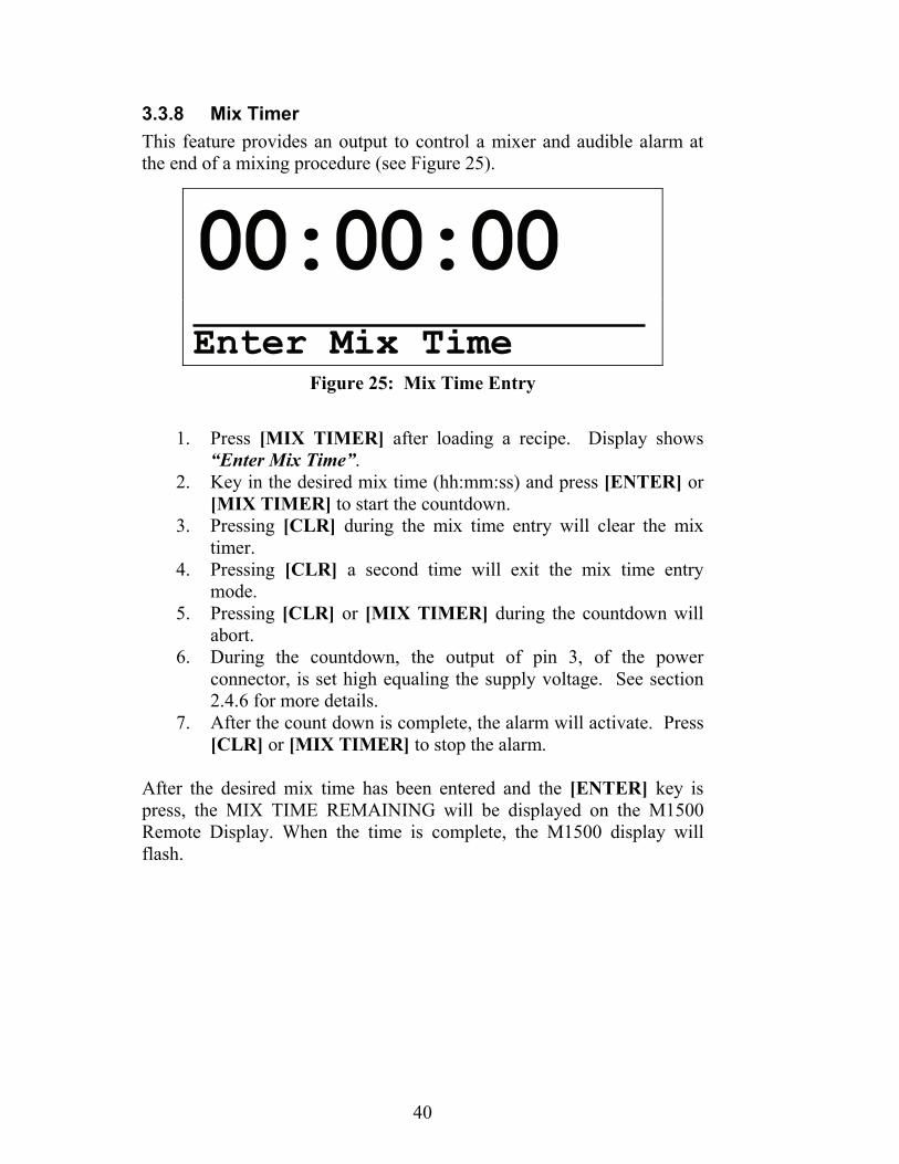
3.3.8 Mix Timer This feature provides an output to control a mixer and audible alarm at the end of a mixing procedure (see Figure 25).
Figure 25: Mix Time Entry
1. Press [MIX TIMER] after loading a recipe. Display shows
“Enter Mix Time”. 2. Key in the desired mix time (hh:mm:ss) and press [ENTER] or
[MIX TIMER] to start the countdown. 3. Pressing [CLR] during the mix time entry will clear the mix
timer. 4. Pressing [CLR] a second time will exit the mix time entry
mode. 5. Pressing [CLR] or [MIX TIMER] during the countdown will
abort. 6. During the countdown, the output of pin 3, of the power
connector, is set high equaling the supply voltage. See section 2.4.6 for more details.
7. After the count down is complete, the alarm will activate. Press [CLR] or [MIX TIMER] to stop the alarm.
After the desired mix time has been entered and the [ENTER] key is press, the MIX TIME REMAINING will be displayed on the M1500 Remote Display. When the time is complete, the M1500 display will flash.
00:00:00
Enter Mix Time
41
Section 4: Recipe Setup This section describes how to setup the recipe database. The Agrifeed 5500 is capable of storing a combination of 500 recipes/ingredients.
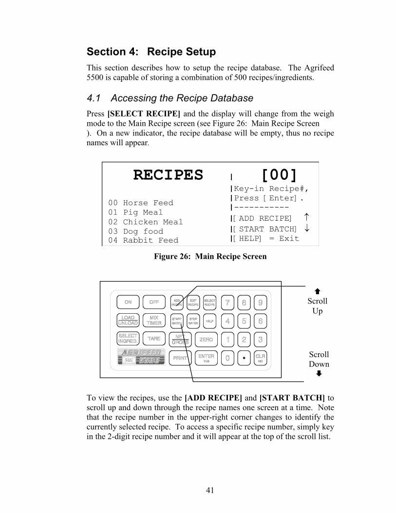
4.1 Accessing the Recipe Database Press [SELECT RECIPE] and the display will change from the weigh mode to the Main Recipe screen (see Figure 26: Main Recipe Screen ). On a new indicator, the recipe database will be empty, thus no recipe names will appear.
RECIPES | [00]|Key-in Recipe#,
00 Horse Feed01 Pig Meal02 Chicken Meal03 Dog food04 Rabbit Feed
|Press [Enter].|-----------|[ADD RECIPE] ↑|[START BATCH] ↓|[HELP] = Exit
Figure 26: Main Recipe Screen
To view the recipes, use the [ADD RECIPE] and [START BATCH] to scroll up and down through the recipe names one screen at a time. Note that the recipe number in the upper-right corner changes to identify the currently selected recipe. To access a specific recipe number, simply key in the 2-digit recipe number and it will appear at the top of the scroll list.
Scroll
Up
Scroll Down

42
Press [HELP] to exit the Main Recipe screen. The recipe identified in the upper-right corner becomes the recipe selected for loading and unloading.
4.2 Adding a Recipe To add a recipe to the recipe database:
1. Press [ADD RECIPE] from the weigh mode. 2. The display shows ‘Searching…’ while looking for the next
available recipe number. When an unused (unnamed) recipe is found the Recipe Name Entry screen appears (see Figure 27).
3. Up to 100 recipes can be defined. Recipe #00 is permanently assigned as a “Preset” recipe that serves as a simple, single ingredient recipe. Recipe #01 - #99 can be must be assigned a custom name before they can be configured and used.
NAME RECIPE #01
ABCDEFGHIJKLMNOPQRSTUVWXYZ +-*/=#$()<>&@
Figure 27: Recipe Name Entry Screen
Use the cursor keys to key in the recipe name. Use the numeric portion of the keypad to enter numbers.

43
Press [ENTER] to save the name and proceed to the Recipe Pre-Alarm screen as described in the following section.
4.2.1 Recipe Pre-Alarm The Recipe Pre-Alarm is used during the unloading process to sound an alarm and flash the display when the pre-alarm weight is achieved. A unique pre-alarm value can be assigned to each recipe. Pre-alarm values are assigned immediately after naming a recipe as described in the previous section.
To assign or change a Recipe Pre-Alarm: 1. Select a recipe number as described in section 4.1 and press
[EDIT RECIPE], or press [ADD RECIPE] to assign a new recipe number.
2. Enter the recipe name as described in section 4.2. A name must be assigned before a pre-alarm value can be entered.
3. Press [ENTER] to accept the recipe name and proceed to the Recipe Pre-Alarm screen (see Figure 28).
4. Key in the pre-alarm weight value and press [ENTER]. The display will then proceed to the Weight Entry Method screen as described in the following section.
Moves left to
previous character
Moves right
to next character
Selects the
character under the cursor arrow
Enters name and completes entry
Deletes the last character of the recipe name

44
RECIPE PRE-ALARM
000000 lb
KEY-IN PRE-ALARM VALUE
[ENTER]=Accept Value [CLR]=Delete
Figure 28: Recipe Pre-Alarm
NOTE: If the PRE-ALARM METHOD parameter in the scale setup is set to “COMMON PRE-ALARM”, then the indicator disregards the Recipe Pre-alarm weight and instead uses the PRE-ALARM WEIGHT specified in the scale setup for all recipes. See Table 6 for more details on the Pre Alarm setup.
4.2.2 Weight Entry Method The weight entry method is selected after entering the recipe pre-alarm when adding new recipes (see section 4.2). The weight entry method cannot be changed when editing a recipe. There are 3 weight entry methods used for loading ingredients:
WEIGHT/LOAD Target weight entered as the actual ingredient weight to be loaded.
WEIGHT/ANIMAL Target weight entered as the amount of each ingredient to be feed to a single animal.
PERCENT/LOAD Target percentage of each ingredient. Target weight will be calculated as a percentage of the total load amount.
Press [YES] to accept the displayed weight entry method and proceed with ingredient selection as described in the following section.
Press [NO] to scroll to the next weight entry method.
45
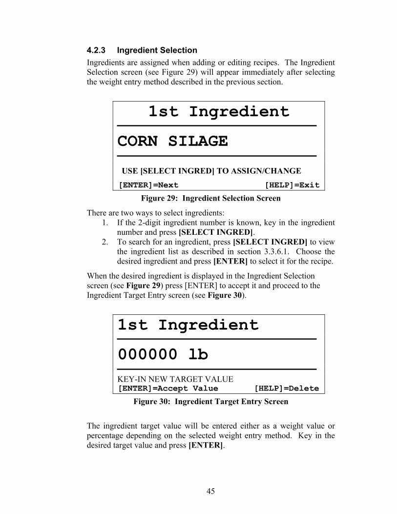
4.2.3 Ingredient Selection Ingredients are assigned when adding or editing recipes. The Ingredient Selection screen (see Figure 29) will appear immediately after selecting the weight entry method described in the previous section.
1st Ingredient
CORN SILAGE
USE [SELECT INGRED] TO ASSIGN/CHANGE
[ENTER]=Next [HELP]=Exit
Figure 29: Ingredient Selection Screen
There are two ways to select ingredients: 1. If the 2-digit ingredient number is known, key in the ingredient
number and press [SELECT INGRED]. 2. To search for an ingredient, press [SELECT INGRED] to view
the ingredient list as described in section 3.3.6.1. Choose the desired ingredient and press [ENTER] to select it for the recipe.
When the desired ingredient is displayed in the Ingredient Selection screen (see Figure 29) press [ENTER] to accept it and proceed to the Ingredient Target Entry screen (see Figure 30).
1st Ingredient
000000 lb KEY-IN NEW TARGET VALUE [ENTER]=Accept Value [HELP]=Delete
Figure 30: Ingredient Target Entry Screen
The ingredient target value will be entered either as a weight value or percentage depending on the selected weight entry method. Key in the desired target value and press [ENTER].

46
Following the target entry, the display prompts for the selection of another ingredient. Repeat the Ingredient Selection procedure for each additional ingredient required. After all required ingredients have been entered, press [HELP] at the Ingredient Selection screen (without selecting another ingredient) to exit and save the recipe.
4.3 Editing a Recipe The procedure for editing a recipe is much the same as adding one. When editing a recipe, it is possible to change the recipe name, pre-alarm weight, ingredients and ingredient targets. Additional ingredients can also be appended to a recipe. It is not possible to change the weight entry method.
To edit a recipe from the weigh mode (see Figure 31): 1. Key-in the desired recipe number and press [SELECT
RECIPE]. The selected recipe number will appear in the lower-right corner of the display.
2. Press [EDIT RECIPE] to display the Recipe Name Entry screen.
3. Refer back to Figure 27 in section 4.2 Adding a Recipe to continue the editing process.
Figure 31: Agrifeed 5500 Weigh Mode
4.4 Deleting a Recipe If you wish to add another recipe but all 100 recipes have already been configured, a message is displayed indicating that you must first delete an existing recipe.
To delete a recipe from the weigh mode: 1. Press [SELECT RECIPE]. 2. Key in the 2-digit recipe number to be deleted and press [CLR].
The display prompts “Delete Recipe?”. 3. Press [YES] to delete the recipe.
00 lb ο
Gross
LOAD Tare 00 lb
Recipe 01

47
4.5 Printing Recipes A list of all named recipes can be printed from the Recipe Selection screen.
To print recipes: 1. Press [SELECT RECIPE] to access the recipe list. 2. Press [PRINT] then, 3. Press [1] as prompted to print only the current recipe. 4. Press [2] as prompted to print all recipes.
Recipes will be transmitted out the printer port.

48
This page is intentionally left blank

49
Section 5: Load / Unload Operation The Agrifeed 5500 is capable of loading and unloading recipes by the touch of the button. Also the indicator is also capable of loading a single ingredient batch using a default recipe ‘RECIPE 00’.
5.1 Loading Ingredients When loading, ingredients can be specified individually or recalled from a recipe.
5.1.1 Selecting Individual Ingredients To load ingredients individually:
1. Make sure the Agrifeed 5500 is in the LOAD mode – if it is in the UNLOAD mode, press [LOAD].
2. Key in the ingredient target weight and press [LOAD]. 3. The display shows the batch target and prompts “Enter Ing#:”. 4. Key in the ingredient number (optional), and press [ENTER]. 5. Begin the loading process (see section 5.1.3).
5.1.2 Selecting a Recipe 1. To load ingredients of a recipe: 2. Make sure the Agrifeed 5500 is in the LOAD mode – if it is in
the UNLOAD mode, press [LOAD]. 3. Select a recipe to load as follows:
Key in the recipe number and press [SELECT RECIPE], or View the recipe list by pressing [SELECT RECIPE]. Refer to section 4.2 for instructions on accessing the recipe database.
4. Press [START BATCH]. 5. Enter the total recipe target value and press [ENTER].
Consider the recipe’s Weight Entry Method: WEIGHT/ANIMAL - Key in the number of animals to feed. The target weight for each ingredient is automatically calculated. WEIGHT/LOAD – The total recipe weight as determined by the individual ingredient targets is shown as the batch target. Press [ENTER] to accept this target, or key in a new target and press [ENTER]. If a new target is entered, all ingredient targets are adjusted in direct proportion to the new target (for this batch only).

50
PERCENT/LOAD – Key in the desired batch target. The target weight for each ingredient is automatically calculated based on the ingredient’s percentage of load.
6. The display shows the first ingredient to load. 7. Press [START BATCH] to begin the loading process (see
section 5.1.3).
-1250 lb ο
Net Ing’t #05 CORN SILAGE START
Figure 32: Start Load Window
NOTE: If the operator does not wish to weigh the ingredient displayed, press [SELECT INGRED] before pressing the [START BATCH] to scroll through the remaining ingredients of the current recipe/batch.
5.1.3 Loading Process When loading, the target weight is displayed as a negative net weight. Fill each ingredient to a net weight of zero (0).
During the loading process, the bottom-right of the display gives an UNDER/GOOD/OVER annunciation. This serves as a visual aide, indicating that loaded weight is over, under or within the desired tolerance.
The Pre-Alarm also provides a visual and audible alarm during the loading process. When the pre-alarm weight is reached, the display back-light flashes slowly, accompanied by a series of warning beeps. When the target weight is reached, the display back-light flashes rapidly along with another series of beeps.

51
5.1.4 Advancing Ingredients To manually advance ingredients: Press [SELECT INGRED]. This records the loaded net weight of the previous ingredient, deletes the ingredient from the loading list, then waits for you to press [START] to begin the loading process for the next ingredient. It is possible to temporarily skip ingredients by pressing [SELECT INGRED] before pressing [START]. Pressing [STOP] during the loading process will record the weight already loaded for the current ingredient, but will not delete it from the loading list. Thus it is possible to load the remaining weight out of sequence at a later time. Pressing [STOP] twice consecutively during the loading process aborts the batch. To advance ingredients automatically: Enable the ADVANCE TOLERANCE parameter in the Scale Setup mode. When the loaded weight is within the specified tolerance for the amount of time specified by the ADVANCE DELAY, the next ingredient is automatically selected. The weight of the previous ingredient is recorded and the ingredient is deleted from the loading list. To Advance Ingredients with Remote Key: Disable the ADVANCE TOLERANCE in the Scale Setup mode and set the REMOTE INPUT ACTION to ‘PRINT/ADVANCE’. Activating the remote key will print a ticket and then advance to the next ingredient similar to the automatic method.
5.2 Unloading Recipes A pen number can be assigned to each location that a recipe is unloaded. When using the AGRIDATA Recipe Management PC software, a pen routing list can be created providing a driver with pen location and unload weight information for multiple pens.
5.2.1 Selecting Individual Pens To unload a recipe to a single pen:
1. Make sure the Agrifeed 5500 is in the UNLOAD mode – if it is in the LOAD mode, press [UNLOAD].
2. Key in the unload target weight and press [UNLOAD]. 3. The display shows the batch target and prompts “Enter
PEN/ID:”. 4. Key in the pen number (optional), and press [ENTER]. 5. Begin the unload process (see section 5.2.3).

52
5.2.2 Selecting Pens from a List This procedure is only used in conjunction with a pen routine list configured by the AGRIDATA Recipe Management PC software.
1. To unload pens from a routine list: 2. Make sure the Agrifeed 5500 is in the UNLOAD mode – if it is
in the LOAD mode, press [UNLOAD]. 3. Press [START BATCH]. 4. The display shows the recipe target for the first pen (see Figure
33: Start Unload Screen 5. ). 6. Press [START BATCH] to begin the unload process for the
displayed pen number (see section 5.2.3). - OR -
7. Press [SELECT INGRED] to temporarily skip the current pen and display the next pen in sequence.
700 lb ο
Net Pen #01 Cow Barn Special Cow Feed START
Figure 33: Start Unload Screen
5.2.3 Unload Process When unloading, the target weight is initially displayed. Unload material to a net weight of zero (0). During the unloading process, the bottom-right of the display gives an UNDER/GOOD/OVER annunciation. This serves as a visual aide, indicating that unloaded weight is over, under or within the desired tolerance.
The Pre-Alarm also provides a visual and audible alarm during the unloading process. When the pre-alarm weight is reached, the display back-light flashes slowly, accompanied by a series of warning beeps. When the target weight is reached, the display back-light flashes rapidly along with another series of beeps.
53
5.2.4 Advancing Pens Press [SELECT INGRED] to advance to the next pen. This records the unloaded net weight of the previous pen, deletes the pen from the routing list, then waits for you to press [START] to begin the unload process for the next pen. When all pens have been deleted from the routing list, the display prompts “RECIPE UNLOADED!”.
When using a pen routing list to unload material, it is possible to temporarily skip pens by pressing [SELECT INGRED] before pressing [START] to unload.
Pressing [STOP] during the unloading process will record the weight already unloaded for the current pen, but will not delete it from the routing list. Thus it is possible to unload the remaining weight out of sequence at a later time.
Pressing [STOP] twice consecutively during the unload process temporarily exits the routing list. Pens that remain in the routing list are not deleted. This allows spot feeding for individual pens not included in the routing list (see section 5.2.1). You can later return to the pen routing list as described in section 5.2.2.
5.2.5 Unloading using Weight / Animal If a recipe uses a weight entry method of Weight/Animal, you can unload material by specifying the number of animals to feed.
To unload using the Weight/Animal entry method: 1. Make sure the Agrifeed 5500 is in the UNLOAD mode – if it is
in the LOAD mode, press [UNLOAD]. 2. Press [START BATCH]. 3. The batch target is displayed in terms of how many animals can
be fed based on the current gross weight. Key in the number of animals to feed, up to the maximum number displayed, and press [ENTER].
4. The display prompts “Enter Pen/ID:”. Key in the pen ID# and press [ENTER].
5. Press [START BATCH] to begin the unload process.
5.2.6 Unfinished Load / Unload If the LOAD or UNLOAD process is stopped without completion, the function will be highlighted on the display. If a LOAD was interrupted and the [LOAD/UNLOAD] key is pressed to switch to UNLOAD, the following prompt will appear:

54
RECIPE NOT COMPLETE! Do you wish to cancel loading the Remaining ingredients? [YES] / [NO]
Selecting “YES” clears the load and returns to the weigh mode. Selecting “NO” exits to the weigh mode and the LOAD will remain highlighted until the batch is complete. If a pen routing list is loaded or an unload is not complete, the UNLOAD will be highlighted. With the UNLOAD highlighted, you may switch to the LOAD mode and do a batch without losing unload data.

55
Section 6: Troubleshooting This section of the manual provides information on error messages, troubleshooting and servicing the Agrifeed 5500 indicator.
6.1 Operational Mode Error Messages
Message Description 02 UnderLoad! Input signal less than negative full scale. If this is due to
excessive loading, reduce the load. Otherwise check the load cell connections. Verify that the scale capacity in section 3.3.2 is correct.
03 Over-Load! Input signal is greater than positive full scale. Use same check as for underload.
04 # > Dsply Number to be displayed will not fit within 6 digits. This will not normally occur for the Gross, Net or Tare Weights. Either clear the totals or settle for only being able to transmit the totals.
05 Zero> Max.! An attempt was made to zero out more than allowed. The allowed value is 10% of scale capacity. Use the [TARE] key for subtracting off container weights or if large dead-load is always to be present, apply this dead-load during the No Load? prompt during calibration to permanently eliminate the offset.
06 Tare>F.S.! Tare entry was greater than full scale. Most likely the entered tare value was incorrect.
07 Tare < 0 ! Negative tare attempted, but not allowed. For auto-tares, the GROSS Weight must be greater than zero unless.
08 CheckConn. This message is displayed if the signal into the A/D is +/- 2 times the Full Scale signal. This is effectively taken into consideration when the information sent to the micro processor from the A/D is +/- twice the allowable F.S. reading. For example, Scale Capacity = 100. Error message will be displayed at +/- 208 taking into consideration the 4% overload.

56
6.2 Hardware Problem Error Messages Message Description 17 A/D BAD! The processor has detected a problem with the A/D chip. 18 BufSzMax! The accumulative total buffer size for both the TX and
RX buffers of all 4 COMM ports on the 650 is 4096 bytes.
19 x06\x44\x61ta&Stop
Certain combinations of protocol are not available. The protocol combination selections are in P201, P202 and P203. This error occurs if an illegal protocol combination is selected.
20 Deflt A/D This message is displayed for 1 second. It will be displayed if the A/D calibration data gets corrupted by whatever means. This message will also be displayed on power-up if the check-sum for the A/D data is corrupted.
21 WriteNVErr Error reading data from the EEPROM. Call GSE Distributor.
22 ReadNVErr Error writing data to the EEPROM. Call GSE Distributor.
23 CheckNVPar Supplementary error message for above errors. 24 NVParFull! The setup being attempted requires more EEPROM than
is currently installed. 25 DefltSetup Upon power-up the indicator has not found the proper
codes. Therefore, all parameters have been reset to factory default values.
26 Bad Setup The stored data has a checksum error. Check all parameters or re-load setup. Refer to section 6.2.1 for instructions on reloading Agrifeed 5500 program.
27 RE-BOOT! The indicator cannot use the EEPROM for data storage, so it is attempting to power-up again to cure the problem.
28 NoRAMAVAIL The current setup requires more RAM than is currently installed. Either contact your dealer or the manufacturer.
29 PIN error This message will appear on power-up or setup if the ram is corrupted in the PIN section. Call GSE Distributor. The access code is then defaulted to the manufacturer (GSE) access code. Also refer to Error 11.
57
6.2.1 Reload Agrifeed 5500 Custom Program If you experience a Code 26 error or Code 60 (New Eprom) on the Agrifeed 5500 unit, the following steps will reload the program back into the indicator. Please be advised that reloading this program may take several minutes to complete. All recipe, ingredient and pen information will be deleted.
1. First press [CLR] [CLR], then key in 100 [NET\GROSS]. 2. The display will prompt “Keyin Code”. 3. Key in the access code 23640 [ADD RECIPE] [ENTER]. 4. Next, key in 65001 [NET\GROSS] to access the “Deflt All”
prompt. 5. Press [TARE] to display “Agri-feed”. 6. Press [ENTER] to display “Sure?”. 7. After a moment the display will prompt “Enter=Dflt”. 8. Press [ENTER] [ENTER] to begin loading the Agrifeed
program. If the display went right to the Agrifeed start up screen, the following steps will load the program from the eprom into the indicator. Please be advised that reloading this program may take several minutes to complete. All recipe, ingredient and pen information will be deleted.
1. Turn the unit off, hold down the [CLR] key and turn the unit back on. Hold down the [CLR] key until the display reads “macro disbl”.
2. Key in 100 [NET\GROSS]. 3. The display will prompt “Keyin Code”. 4. Key in the access code 23640 [ADD RECIPE] [ENTER]. 5. Next, key in 65001 [NET\GROSS] to access the “Deflt All”
prompt. 6. Press [TARE] to display “Agri-feed”. 7. Press [ENTER] to display “Sure?”. 8. After a moment the display will prompt “Enter=Dflt”. 9. Press [ENTER] [ENTER] to begin loading the Agrifeed
program.

58
6.3 Calibration Error Messages
Message Description 30 F.S.>MAX! The entered calibration weight, together with the currently
applied signal, indicates that the full scale signal will be greater than the allowed maximum of the indicator. Verify that correct entries have been made for the scale capacity in Section 3.3.2 and for the calibration weight. Call a GSE distributor.
31 F.S.<.1mVv The entered calibration weight, together with the currently applied signal, indicates that the full scale signal will be less than the allowed minimum of the indicator. Verify the proper entries for the scale capacity in Section 3.3.2 and for the calibration weight. Call a GSE distributor.
32 ADD MORE!
The applied weight during calibration was less than 0.1% of capacity. More weight than this is required.
33 ReCALReq'd The just completed calibration is insufficient to guarantee accurate results due to either the cal weight being less than 5% of capacity or this was the first calibration of this platform to this Indicator and, therefore, the coarse gain was adjusted by the Indicator.

59
6.4 Communication Error Messages Message Description prtyXerror This indicates that the parity of a received character did not
match the parity specified in the COMM PROTOCOL. This could also result if the BAUD RATE is incorrect. The "X" in the error message will be over-written with the associated serial port number. 1= COM PORT 2 = PRINTER
ovrnXerror This indicates an overrun error where an additional character was received while the receive buffer of the Agrifeed 5500 was full and, thus, the extra received character will be lost. The "X" in the error message will be over-written with the associated serial port number. 1= COM PORT 2 = PRINTER
frmgXerror This indicates that the stop bit of a received character did not occur when it was expected. This could be the result of an incorrect BAUD RATE or PROTOCOL The "X" in the error message will be over-written with the associated serial port number. 1= COM PORT 2 = PRINTER
portXerror This indicates that the Agrifeed 5500 did not check its receive data register in time, thus missing a character. If this error should occur, please notify your GSE dealer or the factory. To prevent the problem, try reducing the BAUD RATE. The "X" in the error message will be over-written with the associated serial port number. 1= COM PORT 2 = PRINTER
6.4.1 Data Transmissions If a data transmission of any weight-related numeric data such as Gross, Net or Tare, is sent to the remote as dashes, an overload or under load (negative overload) condition was in effect. Remove the cause of the overload (or under load) and repeat the transmission.
6.4.2 Displayed Weight If an overload or underload occurs due to an electrical overstress (EOS) normally due to lightning or ESD discharge, press [CLR]. The message "wait 1" will appear for about 1 second. The A/D converter will then be reset and the system should again be functional. If not, power down for a few seconds. If the indicator still does not work properly after power-up, check the load cell or platform wiring.

60
6.5 A/D Calibration Procedure The Agrifeed 5500 Analog-to-Digital Converter (A/D) is calibrated at the factory to ensure a stable, linear response to the load cell signal. This calibration procedure calculates critical values that are permanently stored in parameters P61110 – P61121. The A/D calibration should not be confused with the standard weight calibration. It should never be necessary to recalibrate the A/D. However, if the values stored at parameters P61110 – P61121 appear to be reset to 0.00000 and/or 1.00000, then A/D re-calibration is necessary. Contact GSE or your local authorized GSE distributor for more information on this procedure.
WARNING! There are no user-serviceable items in the Agrifeed 5500 indicator! Service must be performed by qualified service technicians only! Attempts to service these indicators by unqualified personnel may void the warranty!

61
Section 7: Agrifeed 5500 Option Kits
7.1 Peripheral Options for the Agrifeed 5500 The capabilities of the Agrifeed 5500 can be expanded with the use of one or more option kits. This section shows the installation procedures for these options.
Available options for the Agrifeed 5500 include the following: Swivel Bracket Kit Remote Display AGRIDATA Recipe Management Software RF Remote Key RF Link

62
7.1.1 Swivel Bracket Installation
Figure 34: Swivel Bracket Installation
Installation Instruction Comments
Unpack the Swivel Bracket Option. GSE part # 44-25-35537
Mount Swivel Bracket on flat surface by securing it through the four mounting holes.
Be sure that when mounting the bracket to a surface it is mounted upright as shown in Figure 34. The five swivel holes should be below the main bracket hole.
Place 4 spacers, on bracket and then insert thumb screws.
Spacer and bracket holes should align with the bracket mounting holes on either side of the enclosure.

63
7.1.2 Remote Display Option Open the remote display unit by removing the six front screws. Remove the connector, GSE part number 26-50-7408P, (see Figure 35) from the bottom of the circuit board. This is done by grabbing the sides of the connector and pulling the connector toward the bottom of the enclosure. Notice that the pins of the connector are labeled at the top of the mating connectors' soldered pins. The cable connecting the Agrifeed 5500 to the Agrifeed 1500 should not exceed 250 ft (76.3m). A 4-twisted pair conductor Teflon cable (GSE part number 22-10-4660), or a 4-twisted pair conductor PVC cable (GSE part number 22-10-4665) is recommended.
Important:
When inserting the pins of the cable to the connector, make sure that the twisted pairs are paired in this order. 1) DAT with DAT- 2) CLK with CLK- 3) DCS with DCS- 4) +5V with GND
Be sure to match the twisted pairs as called out above. Wire the connector according to the table below. Also feed the pigtailed end of the cable through an available strain relief of the Model 1500. The completed cable can be plugged into either of the terminals on the Agrifeed 1500 circuit board (refer to Figure 36). The remaining terminal of the circuit board can be used to connect to an additional Agrifeed 1500 Remote Display. The Agrifeed 5500 Remote Display connector, an 8 pin receptacle, uses a socket mating plug (GSE part number 26-20-1160). When matching the sockets of the plug to the pins of the receptacle, be sure to reference the pin-out labeled on the bottom of the Agrifeed 5500 enclosure. This pin-out label should also be referenced to match the wires of the cable to the Agrifeed 1500 remote display connector. The Model 1500 has annunciators for the Gross and Net modes. The Quantity mode is designated by all annunciators turned off.
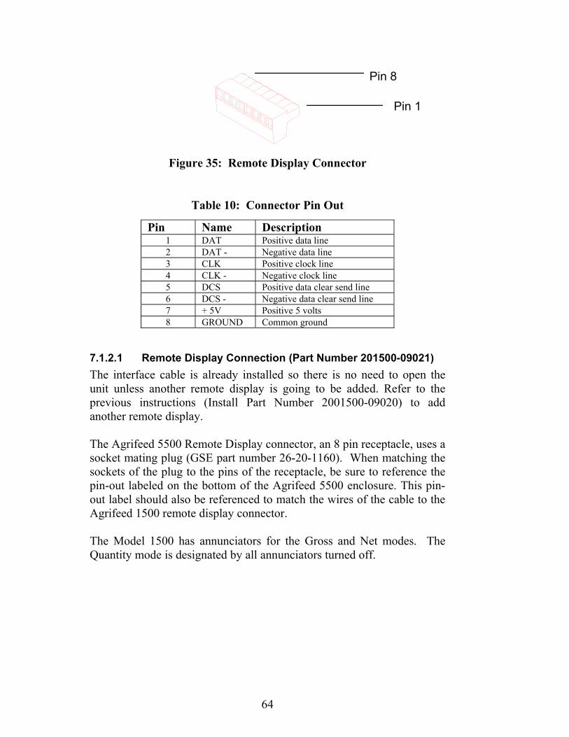
64
Figure 35: Remote Display Connector
Table 10: Connector Pin Out
7.1.2.1 Remote Display Connection (Part Number 201500-09021) The interface cable is already installed so there is no need to open the unit unless another remote display is going to be added. Refer to the previous instructions (Install Part Number 2001500-09020) to add another remote display. The Agrifeed 5500 Remote Display connector, an 8 pin receptacle, uses a socket mating plug (GSE part number 26-20-1160). When matching the sockets of the plug to the pins of the receptacle, be sure to reference the pin-out labeled on the bottom of the Agrifeed 5500 enclosure. This pin-out label should also be referenced to match the wires of the cable to the Agrifeed 1500 remote display connector. The Model 1500 has annunciators for the Gross and Net modes. The Quantity mode is designated by all annunciators turned off.
Pin Name Description 1 DAT Positive data line 2 DAT - Negative data line 3 CLK Positive clock line 4 CLK - Negative clock line 5 DCS Positive data clear send line 6 DCS - Negative data clear send line 7 + 5V Positive 5 volts 8 GROUND Common ground
Pin 8
Pin 1
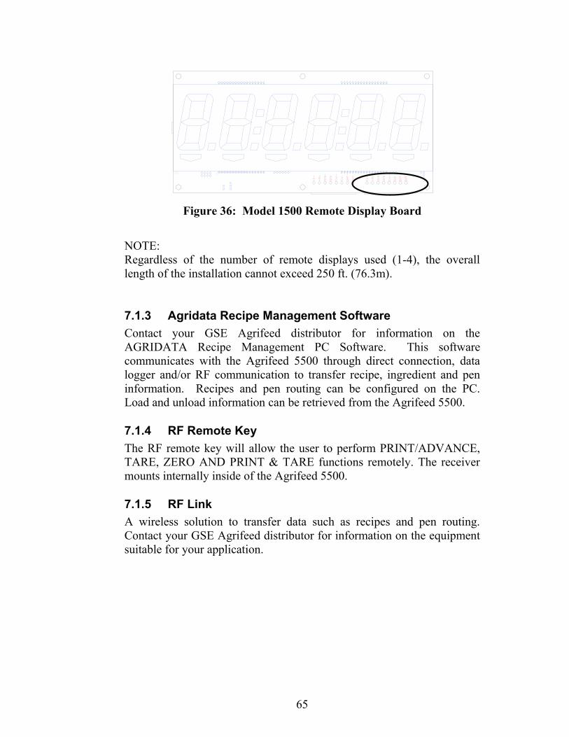
65
Figure 36: Model 1500 Remote Display Board
NOTE: Regardless of the number of remote displays used (1-4), the overall length of the installation cannot exceed 250 ft. (76.3m).
7.1.3 Agridata Recipe Management Software Contact your GSE Agrifeed distributor for information on the AGRIDATA Recipe Management PC Software. This software communicates with the Agrifeed 5500 through direct connection, data logger and/or RF communication to transfer recipe, ingredient and pen information. Recipes and pen routing can be configured on the PC. Load and unload information can be retrieved from the Agrifeed 5500.
7.1.4 RF Remote Key The RF remote key will allow the user to perform PRINT/ADVANCE, TARE, ZERO AND PRINT & TARE functions remotely. The receiver mounts internally inside of the Agrifeed 5500.
7.1.5 RF Link A wireless solution to transfer data such as recipes and pen routing. Contact your GSE Agrifeed distributor for information on the equipment suitable for your application.

31WI-150 Ultra Low-Power Weight Indicator Service Manual

31WI-150 Ultra Low-Power Weight Indicator Service Manual

Agrifeed 5500 Reference Manual
39-10-35715
Issue AD