OPERATION MANUAL MODEL DF1000 DIGITAL WEIGHT INDICATOR ... · (2) 1.1 GENERAL SYSTEM INFORMATION...
51
WESTERN SCALE CO. LIMITED OPERATION MANUAL MODEL DF1000 DIGITAL WEIGHT INDICATOR Revision A © Copyright 1994 1670 Kingsway Avenue, Port Coquitlam, B.C. V3C 3Y9. Telephone: (604) 941- 3474 Fax: (604) 941- 4020 Email: [email protected]
Transcript of OPERATION MANUAL MODEL DF1000 DIGITAL WEIGHT INDICATOR ... · (2) 1.1 GENERAL SYSTEM INFORMATION...

WESTERN SCALE CO. LIMITED
OPERATION MANUAL
MODEL DF1000
DIGITAL WEIGHT
INDICATOR
Revision A© Copyright 1994
1670 Kingsway Avenue, Port Coquitlam, B.C. V3C 3Y9.Telephone: (604) 941- 3474 Fax: (604) 941- 4020
Email: [email protected]

TABLE OF CONTENTS
SECTION ONE - GETTING STARTED . . . . . . . . . . . . . . . . . . . . . . . . . . . . . . . . (1)1.1 GENERAL SYSTEM INFORMATION . . . . . . . . . . . . . . . . . . . . . . . (2)1.2 DF1000 SPECIFICATIONS . . . . . . . . . . . . . . . . . . . . . . . . . . . . . . (3)1.3 UNPACKING AND INSTALLATION INSTRUCTIONS . . . . . . . . . . (4)1.4 OPERATING INSTRUCTIONS . . . . . . . . . . . . . . . . . . . . . . . . . . . . (7)1.5 SETUP . . . . . . . . . . . . . . . . . . . . . . . . . . . . . . . . . . . . . . . . . . . . . . (9)
SECTION 2 - CALIBRATION . . . . . . . . . . . . . . . . . . . . . . . . . . . . . . . . . . . . . . . (10)2.1 STARTING CALIBRATION . . . . . . . . . . . . . . . . . . . . . . . . . . . . . . (11)2.2 PARAMETERS . . . . . . . . . . . . . . . . . . . . . . . . . . . . . . . . . . . . . . . (14)
SECTION 3 - ERROR MESSAGES . . . . . . . . . . . . . . . . . . . . . . . . . . . . . . . . . . (21)
SECTION 4 - TICKET PRINTING . . . . . . . . . . . . . . . . . . . . . . . . . . . . . . . . . . . . (24)4.1 SETTING THE TIME & DATE: . . . . . . . . . . . . . . . . . . . . . . . . . . . (25)4.2 SETTING TICKET FORMATS: . . . . . . . . . . . . . . . . . . . . . . . . . . . (25)4.3 FACTORY TICKET FORMAT: . . . . . . . . . . . . . . . . . . . . . . . . . . . (25)4.4 CUSTOM TICKET FORMAT: . . . . . . . . . . . . . . . . . . . . . . . . . . . . (26)4.5 EXITING TICKET FORMAT MODE: . . . . . . . . . . . . . . . . . . . . . . . (30)4.6 FACTORY TICKET: . . . . . . . . . . . . . . . . . . . . . . . . . . . . . . . . . . . (31)
SECTION 5 - SUPPORT INFORMATION . . . . . . . . . . . . . . . . . . . . . . . . . . . . . (33)SERIAL PORT SETUP . . . . . . . . . . . . . . . . . . . . . . . . . . . . . . . . . . . . . . . (34)
APPENDIX I - DF1000 OPTIONS . . . . . . . . . . . . . . . . . . . . . . . . . . . . . . . . . . . (36)110439 PARALLEL BCD/RS232 OPTION BOARD . . . . . . . . . . . . . . . . . (37)100-159 TK1000 INTERFACE OPTION BOARD . . . . . . . . . . . . . . . . . . . (39)100-166 SETPOINT ISOLATOR/SERIAL PORT BOARD . . . . . . . . . . . . . (41)100-179 4-20 MA OUTPUT OPTION BOARD . . . . . . . . . . . . . . . . . . . . . . (43)
APPENDIX 2 - WIRING DIAGRAMS . . . . . . . . . . . . . . . . . . . . . . . . . . . . . . . . . (45)110439 OPTION - CABLE CONNECTION TABLE . . . . . . . . . . . . . . . . . . (46)DF1000 STANDARD OPTION CABLE . . . . . . . . . . . . . . . . . . . . . . . . . . . (47)RS232 OUTPUT - WIRING DIAGRAMS . . . . . . . . . . . . . . . . . . . . . . . . . (48)100-166 OPTION - WIRING DIAGRAMS . . . . . . . . . . . . . . . . . . . . . . . . . (49)

(1)
SECTION ONE - GETTING STARTED

(2)
1.1 GENERAL SYSTEM INFORMATION
The Western Scale DF1000 Digital Weight Indicator system consists of five mainsub-systems:
- The Analog to Digital Converter.- Single Board Microcomputer.- Display Module.- Keyboard.- Power Supply.
The Analog to Digital Converter converts the analog input signal from the scale loadcells to a digital value which is read and processed by the microcomputer. Commands and data can be input via the keyboard. The microcomputer then sendsdata to the display and output connector.
The functions are performed inside individual modules. By replacing the modulecard, it provides the feature of easy problem isolation and troubleshooting.
SAFETY NOTICE
This unit contains no user serviceable components inside the cabinet. Do not openthe cabinet. Refer servicing and calibration to qualified service personnel.

(3)
1.2 DF1000 SPECIFICATIONS
1. Analog to Digital Converter: Dual slope integration incorporating self-compensating features for maximum stability.
2. Internal Resolution: 120,000 counts, maximum.
3. Displayed Resolution: 20,000 counts, maximum.
4. Transducer Excitation Supply: 10V, 300 mA. Powers up to 10-350 ohm load cells.
5. Transducer Capability: Any strain gauge transducer with full bridge, resistance of 120 to 1200 ohms.
6. Full Scale Input: 6 mv to 40 mv.
7. Measurement Method: Full radiometric with automatic compensation for excitation offsets.
8. Common Mode Rejection: Greater than 120 db at 0 to 100 KHz.
9. Repeatability: +/- 0.01%.
10. Zero Stability: +/- 0.01% of reading for 30 days. If zero tracking is engaged, there will be no noticeable drift until the drift from zero is greater than +/-2% of full scale. Zero temperature stability of better than 0.2 microvolt per C.o
11. Span Stability: +/-0.01% of reading for 30 days and +/-0.03% of reading for six months. Temperature stability of +/-.003% of reading per C from -10 C to 40 C (14 F o o o o
to 104 F).o
12. Display: Up to 6 full digits, 0.4 inch high LED displays (1 cm) high.
13. Operating Temperature: -10 C to 40 C (14 F to 104 F).o o o o
14. Susceptibility: Tested with RF sources at 27 MHz, 150 MHz and 470 MHz. No displaychange with RF field of 2 watts at .5 meters.
15. Power Line Interference: Heavy Duty RFI line filter included.
16. Input Power 120 VAC +/-10%, 50-60 Hz, 0.5 amps maximum.
17. Dimensions and Weight: 11.0" x 8.5" x 4.5": 3 kg or 6.6 lbs.

(4)
1.3 UNPACKING AND INSTALLATION INSTRUCTIONS
1. Unpack the unit and place on a flat surface. Check to see if there is any shipping damage. If so, contact carrier and report damage.
2. Locate the unit in a place where sunlight will not make direct contact.3. Connect load cell and output cable to the rear of the panel. See Fig.1.1.
Press "TEST" on the front panel to check that all display digit segments are illuminated.
5. Your unit is now ready for calibration.
NOTE: Do not connect ll7 VAC to the unit until the load cell and option cables are connected.
NOTE: Refer to table 1.1 for loadcell color codes.
FIGURE 1.1 LOADCELL TERMINATION

(5)
LOAD CELL WIRING GUIDE
EXCITATION EXCITATION OUTPUT OUTPUT SHIELD(+) (-) (+) (-)
Massload Red Black Green White Bare
Revere Green Black White Red Orange
BLH Green Black White Red Yellow
HBM Green Black White Red Bare
Tedea Green Black Red White Bare
Transducers Red Black Green White Orange
Interface Red Black Green White Bare
Genisco Red Black Green White Bare
LeBow Red Black Green White Bare
Ametek Red Black Green White Bare
Sensortronics Red Black Green White Bare
Celesco Red Black Green White Bare
Strainsert Red Black Green White Bare
Pesage Promotion Blue White Red Black Yellow
TABLE 1.1 Loadcell Wiring Guide

(6)
NOTE: Analog ground is connected to electrical (earth) ground inside the DF1000. Load cell cable shields must not connect to ground at any point except Pin 8 of J1. Digital ground is fully isolated and may be connected toalternate grounds at any point.
Avoid potentials exceeding +/- 20 VAC between analog and digital ground.
Unit is shipped for use with 120 VAC unless otherwise noted on rear panel. A card in the fuse/filter on the rear panel allows the voltage to be changed to 240V operation. The 100V and 220V options are disconnected.
FIGURE 1.2 INPUT VOLTAGE SELECTION

(7)
1.4 OPERATING INSTRUCTIONS
1. Apply power to the unit and allow it to warm up for ten minutes.2. Lock out the beam or dial if still in system.3. Upon application of power, the "RESET" lamp will be illuminated. This
indicates the power has been turned on to the unit. In order to extinguish the "RESET" lamp and begin weighing, the "ZERO" key must be pressed.
4. "ZERO"
"ZERO" will only operate when no weight is on the scale. If the unit fails to reset, check that the scale is not binding and that there is no weight of any kind on the deck. Press the "ZERO" key whenever the scale is not showing zero with no weight.
5. "LB/KG"
"LB/KG" selects pounds or kilograms as required.
6. "TARE”, "GROSS/NET", "CLR"
"Pushbutton Tare:With a weight on the scale, press "TARE" to tare off the weight. The display will read zero and the "NET" indicator will illuminate. To display the gross or net weight, press the "GROSS/NET" key as required. Pressing the "CLR" key will erase the tare.
Keyboard Tare: Enter a tare weight via the keyboard and press "TARE". The "GROSS/NET" and "CLR" keys remain the same as for Pushbutton Tare.
NOTE: The displayed weight will be negative if tare exceeds gross.
Tare weights can be recalled for printing, using text code 98, in the Model TK1000 and TK4000(if a 100-159 or 100-166 option board is installed)This text code will prompt "ID" on the indicator for a six digit identifying code, press the desired code number then "P". The indicator then stores the scale weight under that ID number.

(8)
Print code 83 or 93 must be used to print this tare weight. The ID will be printed in the line and character position selected for code 98.
The 100-159 option board must be installed for the above features.
7. "TEST"
Press the "TEST" key to check all front panel lamps. All indicator lamps and display segments will be illuminated for one second. If the scale is in "RESET" condition, the scale weight will be displayed for one second after thelamp test.
8. "ADD" KEY
The DF1000 incorporates a one item totalizer. The total register is cleared onpower up. To add the displayed value (gross or net) to the total register, press the “ADD” key. The current total will be briefly displayed. Each press of the "ADD" key will add the current displayed value to the total register. To display the current total, press '1' then "ADD". The current total will display briefly. To clear the total register and the load counter, press '2' then "ADD".
The load counter is associated with the total register and is incremented by one each time the "ADD" button is pressed and the total updated.
To display the load counter, press "3", "ADD". The load counter can be printed on a TK1000 printer, if the 100-159 option board is installed, or a standard line or ticket printer if the 100-151 or 100-166 option board is installed using text code 80.
9. "RCL" KEY
Pressing the "RCL" (Recall) key will display the current tare value for five seconds. The tare display will illuminate.
The DF1000 is equipped with four independent setpoints. On power up, the setpoints are loaded from the parameters file. See 'Parameters' in Section 2 to change the set-up values. The setpoint values can be changed during operation. To view the current setpoint, press the setpoint number (1-4), then "RCL". The setpoint value will now be displayed. To alter the setpoint, immediately enter the new value and again press "RCL". The new value must be entered within 10 seconds of the value being displayed.

(9)
When viewing the setpoints, caution must be used to prevent the accidental resetting of the setpoint. After selecting a setpoint, it is necessary to wait for the scale weight display to return or press the "CLR" key between setpoint selections.
A feature is provided to rapidly view all four setpoints. Select setpoint 1, or '1' "RCL", then each subsequent press of the "RCL" key will display the next setpoint.
1.5 SETUP
1. Remove the DF1000 top cover.2. Connect the load cell to the load cell connector as per Figure 1.1.3. Connect any option cables as per the wiring diagrams in Appendix 24. Connect 117 volt line cord to the rear of the cabinet and to a separately fused
117 volt outlet.5. Allow fifteen minutes for initial warm-up.
(10)
SECTION 2 - CALIBRATION
2.1 STARTING CALIBRATION

(11)
1. Switch the internal "RUN/CALIBRATE" switch to "CALIBRATE".2. Press the "A/D DISP" key (see below for keyboard layout) , to display the
raw A/D counts.3. Set span switches according to Table I.24. Turn all dead load switches off (down).5. Turn the dead load control fully counterclockwise.6. Ensure that there is no weight on the scale. The reading should be a positive
value and must be adjusted to zero.7. Turn dead load switch 1 on.8. If the reading goes (-), adjust dead load control to zero display.9. If the reading remains (+), turn off 1 and turn on 2.10. Repeat until the display goes (-) and then proceed as in Step 8.11. When zero dead load is obtained, press the "SCALE DISPLAY" key, then
press the "ZERO" key. You are now ready to enter the weighing parameters via the front panel keyboard.
When in the calibrate mode, the keyboard has the functions as shown below.
1 2 3 SCALEDISPLAY
TARE
4 5 6 A/DDISPLAY
ADD
7 8 9 SELECTPARAMETER
RCL
. 0 CLR ENTERVALUE
P (PRINT)
SCALE DISPLAY - displays the scale weight.
A/D DISPLAY - displays the raw A/D converter counts. SELECT PARAMETER - enter a number of one of the parameters described
below, then press this key. The current value for that parameter will be displayed.
ENTER VALUE - enter a new value after selecting a parameter then press "ENTER VALUE".
1,2,3,4,5,6,7,8.9,0 - press these keys to enter numeric data.

% LOAD CELL OUTPUTLIVE LOAD
CELL CAPACITYX 100%
(12)
CLR - press to clear an entry.
% OUTPUT SPAN SWITCHES
3 MV/V CELL 2 MV/V CELL 5 4 3 2 1
Less than 21.5 Less than 32
21.5 - 22 32 - 33 ON
22 - 22.5 33 - 34 ON
22.5 - 23 34 - 35 ON ON
23 - 24 35 - 36 ON
24 - 24.5 36 - 37 ON ON
24.5 - 25.5 37 - 38 ON ON
25.5 - 26.5 38 - 39.5 ON ON ON
26.5 - 27 39.5 - 41 ON
27 - 28 41 - 42 ON ON
28 - 29.5 42 - 44 ON ON
29.5 - 30.5 44 - 46 ON ON ON
30.5 - 31.5 46 - 47.5 ON ON
31.5 - 33 47.5 - 49 ON ON ON
33 - 34.5 49 - 52 ON ON ON
34.5 - 36 52 - 54 ON ON ON ON
36 - 38 54 - 57 ON
38 - 40 57 - 59 ON ON
40 - 42 59 - 63 ON ON
42 - 44 63 - 66 ON ON ON
TABLE 1.2 - SPAN SWITCH SETTINGS
% OUTPUT SPAN SWITCHES

(13)
3 MV/V CELL 2 MV/V CELL 5 4 3 2 1
44 - 47 66 - 70 ON ON
47 - 50 70 - 74 ON ON ON
50 - 53 74 - 79 ON ON ON
53 - 57 79 - 85 ON ON ON ON
57 - 61 85 - 92 ON ON
61 - 66 92 - 99 ON ON ON
66 - 72 99 - 108 ON ON ON
72 - 79 108 - 119 ON ON ON ON
79 - 88 119 - 132 ON ON ON
88 - 99 ON ON ON ON
99 - 113 ON ON ON ON
113 - 132 ON ON ON ON ON
TABLE 1.2(CONT)

(14)
2.2 PARAMETERS
To calibrate a scale, enter the parameters as listed below. In most cases you will only need to enter parameters 1, 2, 3, 4 and 11. The others are all factory pre-set. You need only enter the parameters for either lbs or kg. The values for the second unit will be provided by the indicator. Select lbs or kg before entering the parameters.
1) Decimal Point Position - 0, 1, 2, 3 or 4. Select to correspond with graduation size.
2) Graduation Size - Select one from this table:
LB. .0002/.0005/.0010/.002/.005/.010/.02/.05/.10/.2/.5/1.0/2/ 5/10/20/50/100
KG .0001/.0002/.0005/.001/.002/.005/.01/.02/.05/.1/.2/.5/1/ 2/5/10/20/50/100
3) Overweight - Must be less than 25,000 displayed graduations and greater than one graduation.
4) Motion Window - Enter a weight to determine motion sensitivity. A typical value is 2 times the graduation size.
5) Pushbutton Zero Window % - Can be 0 -99 (%) of overweight value. Should be set to 2 (%) in most cases.
6) Zero Tracking Window - Can be 0-99 (%) of 1 graduation. Should be set to 60 (%) in most cases.
7) Zero Tracking On-Off - 1 = On; 0 = Off.
8) Average Shift 1 - The system has a register which averages 10 scale readings. When the raw scale reading changes less than "Average Shift 1" counts, no new readings are shifted into the register, resulting in a very stable display. A typical value for "Average Shift 1" is 3 (approximately 1/2 display graduation.)
9) Average Shift 2 - When the raw scale reading changes more than "Average Shift 1" counts, the new reading is shifted into the register once. The averaged reading changes slowly over 10 readings. A typical value for "Average Shift 2" is 500 (approximately 2 display graduations.)
(15)
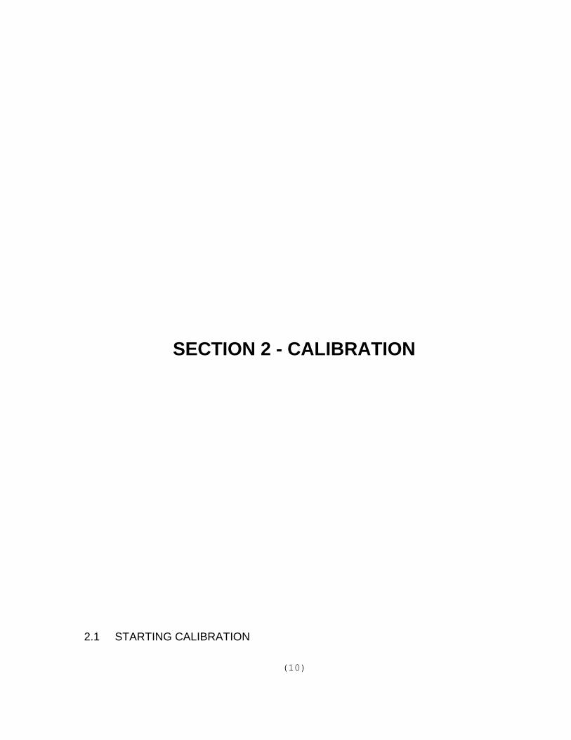
10) Average Shift 3 - When the raw scale reading changes more than "Average Shift 2" counts and less than "Average Shift 3" counts, the new reading is shifted into the register 5 times. The averaged reading changesquickly over two readings. A typical value for "Average Shift 3" is 1000 (8 display graduations.)
When the raw scale reading changes more than "Average Shift 3" counts, the new reading is shifted into the register 10 times. This forces the averaged reading to change instantly to the new reading.
11) Set Span - The DF1000 utilizes a 7 entry span calibration system to assistin linearity adjustments during scale calibration.
Before calibrating a scale with the Set Span function, select Parameter 12 and enter '1' to reset the span table.
Now the Set Span function may be used as follows:
a) Remove all weight from the scale.
b) Press the "ZERO" key to zero the scale:
If the load cells are non-linear If the load cells are linear only(+/-2 counts maximum) up to six one calibration point needs to becalibration points may be entered entered.to linearize the cell.
c) Place approximately 1/6 scale c) Place approximately 2/3 scale capacity weight on the scale capacity on the scale and press and press "11", "SELECT". "11", "SELECT".
d) Enter the correct weight (NN.NN d) Enter the correct weight (NN.NN "ENTER"). "ENTER").
e) Repeat Steps (c) and (d) until a maximum of six weight values have been entered.
12) Reset Span Table - Clears the span table except for the first entry. Do this before calibrating. When you have selected this function, press '1' AND ‘ ENTER'.
Note: This will clear any previous calibration.

(16)
13) Motion Settle Time - Enter the number of 0.25 second intervals for which 'Motion' will remain asserted after scale reading stabilizes to within the 'Motion Window' tolerance. A typical value is 8 (2 sec.).
14) Reload Factory Values - Calibrates the scale with commonly used values. When you have selected this function, press '1 ENTER'.
Note: This will clear any previous calibration .
15) Power-On Units Select - 1 selects KG; 0 selects LB.
16) Decrement Span Pointer - Allows you to re-position the span table pointer to re-enter calibration points without starting the enter span calibration over. When you have selected the function, press '1' and ‘ENTER'.
17) Increment Span Pointer - Same as under (16).
18) Serial Port Speed - Enter the Baud rate of the serial data port:
1 = 9600 Baud2 = 12003 = 300
19) Data Transmission Code -
Mode 1 = Output only when Print button pressed. This mode outputs the displayed weight in standard serial string format. The received data line is used for output flow control. This mode is typically used with a local printer to print the weight. Flow control would be accomplished by connecting the printers “Busy” line to the indicators “Receive” line.
For the standard data string see SECTION 5
Mode 2 = Output when Strobe = 0.(Strobe is Pin 18 on DF1000 data connector.)Outputs the standard data string. Whenever the "Receive" data line is in State 0, the indicator will output continuously if State 0 is maintained.

(17)
Mode 3 = Output when Strobe = 1
Outputs the standard data string. Whenever the "Receive" data line is in State 1, the indicator will output continuously if State 1 is maintained.
Mode 4 = Output when ASCII "?" is received.
The indicator outputs the standard data string whenever a "?" character is received on the "Receive" data line.
Mode 5 = Continuous output.
The indicator continuously transmits the standard data string.
Mode 6 = Keyboard ID.
This mode is used to retain ID's in memory for use or change on each print cycle. A six digit number can be entered after pressing the "PRINT" button. When the "PRINT" button is pressed again, the six digit number is appended to the standard data string.
Example:
1 2 3 4 5 6 7 8 9 0 1 2 3 4 5 6 7 8 9 0 1 2 3 4
2 3 0 0 0 K G G R 1 2 3 4 5 6 (CR) (LF)

(18)
Mode 7 = Serial port transmission.
Allows the use of the Model TK1000 print functions through the indicator's serial port when the indicator is interfaced with a standard serial printer.
Print format details are provided in SECTION 4.
The following are exceptions to TK1000 programming:
- only single (86) and double wide (84) character sizes and normal print supported.
- text character codes 70-79 inclusive are not recognized.
- The first digit only of character position 42 determines thenumber of line feeds. Note: Most serial printers have an autoline feed after reception of a complete line of characters.
For wiring details see Appendix 2.
20) USA Display Flag - The USA display flag can be set to either '0' or '1'. Setting the flag to '0' gives the standard display. Setting the flag to '1' causes the following display changes:
a) Dead Zeros - The active digit will always be displayed at zero (i.e. for grad size of 10, the zero display will be '00'.)
b) Dead Zeros behind Decimal Points - For the grad size of 10/5 and 100/50, the extra dead zero shown in the Lbs mode will be blanked. This is only effective for decimal positions greater than '0'.
The USA flag must be enabled '1' for the indicator to be legal for trade in the U.S.A.
21-24) Setpoint Presets - Four setpoints are provided in the DF1000. Upon power up the setpoints are loaded from the parameters file. Enter the start up setpoint value to the appropriate setpoint (21 = Setpoint 1, 22 = Setpoint 2, 23 = Setpoint 3 and 24 = Setpoint 4).

(19)
25) Setpoint Polarity - Each of the four setpoints can be set to energize if the weight is less than its setpoint or energize if the weight is greater than or equal to the setpoint. To set the polarity a mask is entered. Four digits are required. A '0' sets the setpoint to energize when the weight is greaterthan or equal to the setpoint. A '1' sets the setpoint to energize when the weight is less than the setpoint.
Typical Setpoint Polarity Entry -
1 0 1 0
Setpoint 4 Setpoint 3 Setpoint 2 Setpoint 1Wt < Setpoint Wt >= Setpoint Wt < Setpoint Wt >= Setpoint
Note - Leading Zeros will be blanked on the display, but must be entered.
26) Power Up Reset Flag - The power up reset flag allows designation of the power push to the zero mode. If this flag is '0', the indicator will start with its push to zero register cleared and the weight display active. If this flag is '1', the weight display will show all '8's until an initial push to zero occurs. To be legal for trade, this flag must be set to '1'.
27) Number of averages performed,
1=10 2=20 5=50 10=100 Factory set to 1.
28) Shift Delay 1 - Hold over delay from half table load to single entry load intoAverage Table in 0.33 second increments. Maximum 30.
29) Shift Delay 2 - Same as #28, but from full table load to half table load. Maximum 30.
30) Tare offset value - When the 'Zero' button is pushed, the scale will be forced to this value. If this parameter is non-zero, then the Tare button willnot work. An error 35 will result. Error 21 occurs if DF1000/printer chips are retrofitted into an old unit. Reloading this parameter will cure the problem without destroying the calibration.
31) Non-destructive test the EEPROM chip U4. You will be prompted if this chip is bad.
32) Enter Printer SETUP mode. See Section 4.

WEIGHT( NET OR GROSS) x 16mAD/ A SPAN VALUE
� 4 OUTPUT( mA)
(20)
33) D/A Converter Output Selector. The parameter determines if D/A output is from Gross (0) or Net (1) weight values. (Option 100-179 is required.)
34) D/A Output Span Value. This value is automatically set to the indicator's over range value. This value can be changed to increase or decrease the output span value. The following formula determines the 4-20mA output.

(21)
SECTION 3 - ERROR MESSAGES

(22)
DF1000 ERROR MESSAGES
'1' - Invalid Tolerance Selection.
'2' - Graduation Size Invalid.
'3' - Decimal Point Position Invalid.
'4' - Flag Select must be 0 or 1.
'5' - Pushbutton Zero % must be 0-99.
'6' - Auto Zero % must be 0-99.
'7' - Only Value '1' will reset parameters.
'8' - Only Value '1' will reset span table.
'9' - Span exceeds maximum capacity and/or entry too small.
'10' - Cannot set span using negative values.
'11' - Span table is full.
'12' - Delay maximum = 99/Delay of '0' not permitted.
'13' - 0 = LB: 1 = KG only.
'14' - Average value entry out of range.
'15' - Overweight entry out of range.
'16' - Motion window out of limits.
'17' - Increment only with entry of 1.
'18' - Decrement only with entry of 1.
'19' - Cannot decrement span point < 1.
'20' - Parameter memory write error.
'21' - Parameter Checksum error.

(23)
'22' - Program Checksum error.
'23' - Serial speed 1-3 only.
'24' - Transmission codes 1-7 only.
'25' - Cannot increment span pointer past > 8.
'26' - Entry is larger than scale capacity.
'27' - Entry of '0' or '1' only allowed.
'28' - Only setpoint selects of 1-4 valid.
'29' - Only 1 or 2 allowed in 'ADD' selection.
'30' - Scale is invalid (over, negative or in motion).
'31' - Only 1, 2, 5 or 10 allowed in shift size.
'32' - Holdover delays range is '0 - 30'.
'33' - Printer SETUP checksum error. This error occurs if DF1000/Printer chips are retrofitted into an old unit. Reloading the factory ticket cures this.
'34' - Tare offset out of limits. 10001 or 100.1 or 10.1 or 1.001 kg. maximum.
'35' - Tare pushbutton disabled if Tare offset (parameter 30) is non-zero.
'36' - Span Factor is out of range for Parameter 34.

(24)
SECTION 4 - TICKET PRINTING

(25)
4.1 SETTING THE TIME & DATE:
- Set "Run/Calibrate" to "Run".- Press "10P". Respond to "CLOC" prompt by pressing four digits for
hour-hour-minute-minute, then "P".- Respond to "And" prompt by pressing six digits representing
day-day-month-month-year-year, then "P".
4.2 SETTING TICKET FORMATS:
- Set "Run/Calibrate" switch to "Calibrate".- Enter Ticket Setup parameter by pressing "32 SELECT".- In this mode, the display and keyboards take on different functions as
follows:
KEYBOARD LAYOUT FOR PRINTER SETUP MODE:
4.3 FACTORY TICKET FORMAT:
- Press "RELOAD", press "RELOAD".
- When horn stops sounding, entry is complete. Ticket can be printed by switching to Run mode and pressing "P". See the sample Factory Ticket.
NOTE: ANY CUSTOM TICKETS PREVIOUSLY ENTERED WILL BE DESTROYED IF FACTORY TICKET IS REENTERED.

(26)
4.4 CUSTOM TICKET FORMAT:
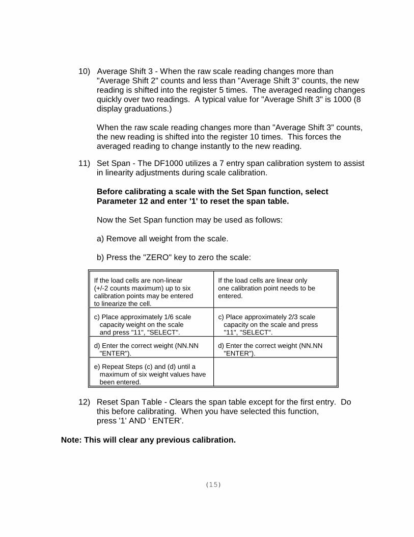
Before starting to enter custom ticket formats, ensure that the memory is entirely clear of all previous entries (press "CLEAR", press "CLEAR"). When horn stops sounding all character positions have been cleared to spaces (Code 48). Make a drawing of what you would like the ticket to look like before starting. Use the accompanying TICKET WORKSHEET to lay out the codes you wish to use. To enter a character, make sure you are at the intended line number and character number. Type the number representing the desired character, then press "ENTER". The character will be permanently stored in memory and the next character in sequence will be displayed. The ticket setup memory is arranged as 40 lines, with 43 characters per line.
To save new data and exit Printer Setup mode, press "EXIT". "DONE" will be displayed momentarily when the function is complete.
Character 00 determines the print size and type of print. For the first line of anyticket it also determines whether or not to perform Top of Form search.
Print control codes to be used in character position '00' are as follows:
NORMAL INVERSE MIRROR
TOF NO TOF TOF NO TOF TOF NO TOFSEARCH SEARCH SEARCH SEARCH SEARCH SEARCH
QUAD 83 67 51 35 19 03
DOUBLE WIDE 84 68 52 36 20 04
DOUBLE HIGH 85 69 53 37 21 05
SINGLE 86 70 54 38 22 06
e.g. Placing 36 in position '00', line '00' causes Top of Form search to besuppressed and the first line of the first ticket to be printed upside down in doublewide characters.
Any codes other than those listed above in position 00 cause the line to be ignoredby the printer.
Character 41 determines the direction of paper feed or end of ticket.

(27)
Codes for Character 41 only: 87 - Line Feed toward operator. 88 - Line Feed away from operator. 99 - End of Ticket.
Ten different ticket formats can be programmed into the DF1000. Each must endwith code 99 in character position 41. To initiate a particular format the operatorpresses the number associated with that format then "P". Pressing "P" aloneselects the first format, "1" then "P" selects the second, "2" then "P" selects thethird, etc.
Note: The Run/Calibrate switch must be in the "Run" position to print a ticket.
Character 42 determines the distance in 0.02 inch steps that the paper will feedbefore the next line of print. Any number from 00 to 99 can be entered.
e.g.: To move the paper 0.5 inches enter 25 (0.5 - 0.02 = 25) in character 42.
Code for character 42 only:
00 - 99 Number of line feed steps, 0.02" per step.
Characters 1 through 40 contain the text and data to be printed. Text and data maybe inserted in the ticket by entering the appropriate two digit code at each location. In response to "CLEAR", all positions default to Code 48 (space) so only codesother than 48 will have to be entered.
Character per line capacity is forty for single size, twenty for double and ten forquad.

(28)
TEXT CODES FOR CHARACTERS 1 TO 40
0 00 A 17 R 34 # 51 { 68
1 01 B 18 S 35 $ 52 } 69
2 02 C 19 T 36 % 53 ~ 70
3 03 D 20 U 37 & 54 71 narrow block
4 04 E 21 V 38 ' 55 72 wide block
5 05 F 22 W 39 ( 56 + 73 inter- section
6 06 G 23 X 40 ) 57 - 74 horizontal line
7 07 H 24 Y 41 * 58 75 vertical line
8 08 I 25 Z 42 + 59
9 09 J 26 [ 43 , 60
: 10 K 27 \ 44 - 61
; 11 L 28 ] 45 . 62
< 12 M 29 ̂ 46 / 63
= 13 N 30 _ 47 l 64
> 14 O 31 space 48 b 65
? 15 P 32 ! 49 k 66
@ 16 Q 33 " 50 g 67

(29)
DATA Codes for characters 1 - 40 only
89 - Time HH:MM 5 characters printed. 90 - Date MMM/DD/YY 9 characters printed. 76 - Add displayed weight to total. 77 - Clear total. 78 - Increment load counter. 79 - Clear load counter. 80 - Print load counter.
All weights are ten characters long, including kg or lb (leading zeros are blanked).
91 - Keyboard-entered gross weight
92 - Scale weight (Gross) 93 - Tare weight, (Scale weight, or stored weight) 94 - Net weight, (KBD gross - scale) 95 - Net weight, (Gross - tare) 96 - Total weight 97 - Displayed weight, (Scale or net) 98 - Identification number, (ID) six digits, leading zeros are blanked.
99 - Gross weight (Scale weight or stored weight)
Use codes 81 to 87 if weight is to be printed WITHOUT units. Functions are thesame as for codes 91 to 97 respectively.
If ID and/or KBD Gross are to be printed, you will be prompted for appropriatekeyboard entry, then the most recently entered value will be displayed foracceptance (press "P") or change (enter new value and press "P").
Any weight must be valid to be printed, i.e. must not be negative, motion oroverweight.
To store tare or gross weights by ID for recall at print time, use code 98 followed by:
48 to prompt for ID only00 to store scale weight by ID01 to store scale weight by ID only if new02 to recall Tare or Gross by ID03 to recall Tare or Gross by ID and remove from table
The stored weight identifier ID is printed where code 98 is used.

(30)
When printing a ticket, respond to the “ID” prompt by pressing a unique six digitrecall number then ‘P’.
To print the ID table, press ‘11' then ‘P’To clear the ID table, press ‘12' then ‘P’
To print net weight delivered, Press ’TARE’, discharge material, then print Gross,Tare, Net using codes 99, 93 and 95 respectively.
NOTE: If “bad scale” error message appears on last discharge, press ‘GROSS’ then ‘ZERO’
NOTE: ALL TK1000 PRINT CONTROL CODES PERFORM THEIR DESIGNATED FUNCTION IN THE SAME ORDER AS THEIR LINE AND CHARACTER POSITION ASSIGNMENT. ALL DATA ACQUISITION AND/OR ENTRY IS COMPLETED BEFORE PRINTING STARTS.
4.5 EXITING TICKET FORMAT MODE:
To save the new data and exit the ticket format mode, press ‘EXIT’. “DONE” isdisplayed momentarily when the function is complete.

(31)
4.6 FACTORY TICKET:
Below is a sample of the factory ticket.(Not actual size)
(32)

SECTION 5 - SUPPORT INFORMATION
(34)
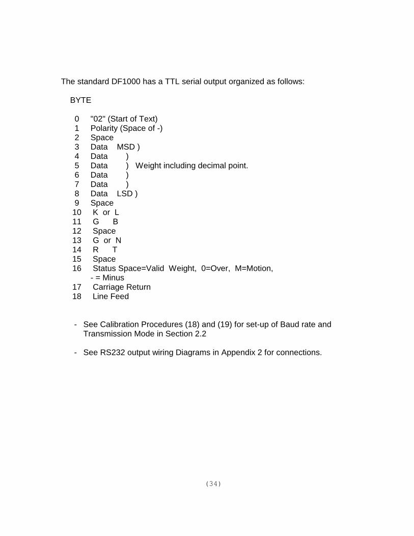
The standard DF1000 has a TTL serial output organized as follows:
BYTE
0 "02" (Start of Text) 1 Polarity (Space of -) 2 Space 3 Data MSD ) 4 Data ) 5 Data ) Weight including decimal point. 6 Data ) 7 Data ) 8 Data LSD ) 9 Space 10 K or L 11 G B 12 Space 13 G or N 14 R T 15 Space 16 Status Space=Valid Weight, 0=Over, M=Motion, - = Minus 17 Carriage Return 18 Line Feed
- See Calibration Procedures (18) and (19) for set-up of Baud rate and Transmission Mode in Section 2.2
- See RS232 output wiring Diagrams in Appendix 2 for connections.

(35)
Optional 110439 BCD/RS232card:
- Has RS232 Serial output organized as shown above.- Has Binary Coded Decimal output as follows:
- 6 digits.- Motion, overrange, minus, gross/net, lb/kg, and ready status outputs.- Positive and negative data strobes.
- Serial and parallel outputs occur simultaneously.
NOTES:
- Connections are made via a 37-Pin D-Type connector.- The I/O board is not necessary for "TTL" serial output as the standard DF1000
includes TTL serial I/O.- DF1000 interfaces to the AP line of printers without the I/O card.- Early DF1000's without an output connector can be modified for TTL serial and
I/O card use by changing the two 2732's to the current program version and adding an output connector.

(36)
APPENDIX I - DF1000 OPTIONS

110439 PARALLEL BCD/RS232 OPTION BOARD
This option board provides parallel BCD outputs as well as status lines. Alsoincluded are RS232 drivers to convert the indicator's serial port from TTL to RS232levels. No setpoints are available with this option, use the 100-166 option with thisoption for parallel output and setpoints.
SPECIFICATIONS:
- 6 Digit BCD Output.- true logic 0=0, 1=1- Status output consisting of:
units (0=lb/1=kg)gross/net (0=gross/1=net)ready (0=ready)motion (1=motion)minus (1=minus)over (1=over)
- Print pulse output, when the front panel Print button is pressed. Pulse will only occur if the indicator is displaying a valid weight and is not in motion.
- All outputs are TTL compatible.- Output low voltage = 0.4 VDC @ 1.6 mA.- Output high voltage = 2.4 VDC @ 205 ua
- 5 VDC supply maximum current 50 mA for external use.
- RS232 conversion for the indicator's serial port:- V low = -9 VDC- V high = +9 VDC
- meets standard RS232 driver specifications.

(38)
INSTALLATION OPERATION:
1) Remove power from the indicator.2) Remove the indicator cover.3) Examine the indicator to determine if any option boards are installed. If
no option boards are installed, you will require a ribbon cable for the installation. If an option board is already installed, you will require a "Y" cable.
4) If the DF1000 standard option cable is currently installed, remove it.5) If an option board is installed, remove the blanking plate next to it.6) Observing the key way, plug the ribbon cable into connector J3 on the
100-132 board.7) Replace the indicator cover.8) Prepare the mating cable for the parallel port using the connector wiring
diagram in Appendix 2. If you are using the RS232 option of this card, see Appendix 2 for connection details. Serial port setup information is located in Section 5.
9) Connet the parallel or serial cable to the 110439 option card.

(39)
100-159 TK1000 INTERFACE OPTION BOARD
This option board is required to send print data to the Model TK1000 Ticket Printer. The Model TK1000 utilizes the microprocessor in the digital indicator for its printingfunctions. This option card provides the drivers for the TK1000 printer and a timeand date clock with battery backup.
This option can also be used to provide formatted printing through the indicator'sserial port. A 110439 or 100-166 option is required to convert the indicator's serialport to RS232 levels for most common line or ticket printers.
SPECIFICATIONS:
This option board is intended only to drive the TK1000 ticket printer from its outputboard. It is not designed to provide parallel or serial output signals for any otherpurpose. Specifications for this port are not provided.
NOTE: Do not connect the output of the 100-159 to any RS232 or Parallel type printers. Damage will occur to either the 100-159 option card or the connected devices.
INSTALLATION:
1) Remove power from the indicator.2) Remove the indicator cover.3) Examine the indicator to determine if any option boards are installed. If
no option boards are installed, you will require a ribbon cable for the installation. If an option board is already installed, you will require a "Y" cable.
4) If the DF1000 standard option cable is currently installed, remove it.5) If an option board is installed, remove the blanking plate next to it on the
rear of the indicator chassis.6) Observing the key way, plug the ribbon cable into connector J3 on the
100-132 board.7) Replace the indicator cover.

(40)
8) If a TK1000 printer is to be used, connect the TK1000 interconnect cable to the option board connector. This cable should already be connected tothe TK1000 Printer. Refer to the TK1000 manual for unpacking and installation procedures for the TK1000.
9) Apply power to the indicator and TK1000 (if used). Follow the instructionsin Section 4 of this manual to setup and format the required ticket printouts.

(41)
100-166 SETPOINT ISOLATOR/SERIAL PORT BOARD
The 100-166 Setpoint Option board provides optically isolated setpoints for theDF1000 Digital Indicator. In addition, RS232 drivers are provided for the serial port. This option can be used in conjunction with the 100-151 board to provide BCD,RS232 and isolated setpoints.
SPECIFICATIONS:
- Setpoint Outputs- four optically isolated setpoint outputs.- common supply for all four setpoints; supply for setpoints can be internal
5 VDC (maximum 50mA) or from an external source.- each output can source up to 75mA @ 40 VDC.- outputs can be configured by DF1000 software to either be normally
open or normally closed.- RS232 conversion for the indicator's serial port.
- V low = -9 VDC.- V high = +9 VDC.- meets standard RS232 driver specifications.
INSTALLATION:
1) Remove power from the indicator.2) Remove the indicator cover.3) Examine the indicator to determine if any option boards are installed. If
no option boards are installed, you will require a ribbon cable for the installation. If an option board is already installed, you will require a "Y" cable.
4) If the DF1000 standard option cable is currently installed, remove it.5) If an option board is installed, remove the blanking plate next to it on the
rear of the indicator chassis.6) Install the100-166 option board with the component side facing the
power transformer.7) Observing the key way, plug the ribbon cable into connector J3 on the
100-132 board.

(42)
8) If you will be powering the setpoint devices using the indicator's internal 5Volt supply, ensure that the jumper J3 on the option board in the "INT" position.
If you are using external power for the setpoints, select the "EXT" position.
If a 100-151 option board is installed in the indicator, ensure that jumper J4 is removed. Serial RS232 data will be available only from the 100-151option board connector. If there is no 100-151 option, ensure that jumperJ4 is in the "RS" position.
9) Prepare and connect a mating cable for the Setpoint/RS232 outputs using the wiring diagrams in Appendix 2.
Note: If you have a 100-151 option board, do not use the RS232 outputs on this option card, use the outputs on the 100-151 option board andensure that jumper J4 is in the "RS" position.
10) Connect the cable to the option board.
11) Apply power to the indicator and test. Setpoint and serial port configuration details are provided in Section 2 of this manual.

(43)
100-179 4-20 MA OUTPUT OPTION BOARD
This option provides an isolated 4-20mA signal to control external devices. Theoutput is scaled to the indicator's full scale value. Either the gross or net scaleweight can be selected for output control.
SPECIFICATIONS:
- Isolated 4-20mA output.- Drives loads up to 600 Ohms.- Power requirement; 24VDC @ 50 mA unregulated. (Plug in adapter
provided.)- Output isolated from indicator electronics and chassis (600 VDC
maximum). INSTALLATION & OPERATION:
1) Remove power from the indicator.2) Remove the indicator cover.3) Examine the indicator to determine if any option boards are installed. If
no option boards are installed, you will require a ribbon cable for the installation. If an option board is already installed, you will require a "Y" cable.
4) If the DF1000 standard option cable is currently installed, remove it.5) If an option board is installed, remove the blanking plate next to it on the
rear of the indicator chassis.6) Observing the key way, plug the ribbon cable into connector J3 on the
100-132 board.7) Replace the indicator cover.8) Plug the mating DB25S connector into the 100-179b.9) Hook up the 4-20ma output and 24VDC adapter as follows:
DB25S
4-20ma SOURCE---------------------------- 124-20ma RETURN---------------------------- 13+24VDC---------------------------------------- 24COMMON-------------------------------------- 25

(44)
11) Apply power to the indicator and enter calibration. Indicator parameters 33 and 34 apply to this option board. Normally, these parameters are automatically set to span the 4-20mA output to the indicator's maximum capacity. See Section 2 for adjustment details. There are two potentiometers on the option board, R1 is span and R2 is offset. These pots are factory adjusted and usually do not require field adjustment.

(45)
APPENDIX 2 - WIRING DIAGRAMS

(46)
110439 OPTION - CABLE CONNECTION TABLE
1 COMMON 2 BIT 0 ] 3 1 ] LSD 4 2 ] BCD 5 3 ] 6 BIT 0 ] 7 1 ] #1 8 2 ] BCD 9 3 ] 10 BIT 0 ] 11 1 ] #2 12 2 ] BCD 13 3 ] 14 BIT 0 ] 15 1 ] #3 16 2 ] BCD 17 3 ] 18 --- 19 --- 20 --- 21 BIT 0 22 1 23 2 24 3 25 BIT 0 26 1 27 2 28 3 29 0 30 1 31 2 32 3 33 4 34 5 35 6 36 7 37 ---
RECEIVE DATA RS2325 VDC (50 ma MAX.)COMMON]] #4] BCD]]] MSD] BCD]- PRINT PULSE+ PRINT PULSEUNITS (1=KG)GROSS/NET (1=NET)READY (1=NOT READY)MOTION (1=IN MOTION)MINUS (1=MINUS)OVER (1=OVER)TRANSMIT DATA RS232
NOTES: - All output use standard logic (0=Low=<.6VDC, 1=High=>1.2VDC) - RS232 Connections marked in bold - RS232 input and outputs provide formatted print strings. See Section 5 for details.

(47)
DF1000 STANDARD OPTION CABLE

(48)
RS232 OUTPUT - WIRING DIAGRAMS

(49)
100-166 OPTION - WIRING DIAGRAMS