DIGITAL VIDEO CODING STANDARDS - MPEG-1/2 VIDEOshi/courses/ECE789/ch16.pdf · 16.1.1 Digital Video...
42
Chapter 16 DIGITAL VIDEO CODING STANDARDS - MPEG-1/2 VIDEO 16.1 Introduction • MPEG-1 video standard: completed in 1991 Officially referred to as: ISO 11172 Developed for CD-ROM applications Up to about 1.5 Mbps • MPEG-2: completed in 1994
Transcript of DIGITAL VIDEO CODING STANDARDS - MPEG-1/2 VIDEOshi/courses/ECE789/ch16.pdf · 16.1.1 Digital Video...

Chapter 16
DIGITAL VIDEO CODING STANDARDS - MPEG-1/2 VIDEO
16.1 Introduction
• MPEG-1 video standard: completed in 1991
Officially referred to as: ISO 11172 Developed for CD-ROM applications Up to about 1.5 Mbps
• MPEG-2: completed in 1994

2
ISO 13818 (ITU-T Recommendation H.262) Developed to provide video quality not lower than NTSC/PAL and up to HDTV 2 to 30 Mbps (4 Mbps is chosen for optimizing MPEG-2) A superset of MPEG-1 (backward compatible to MPEG-1)
• MPEG only specifies:
Syntax for creation of a legitimate MPEG bitstream
⇒ Only specifies decoding, leaving encoding open
16.1.1 Digital Video Format
♦ Progressive and Interlaced

3
§ Currently, most video signals generated by a TV camera: interlaced.
ü 30 frames per second for NTSC ü Each frame has two fields: top field and
bottom field, 1/60 second apart. ü In displaying an interlaced frame, top field
scanned first, bottom field scanned next. ü Top and bottom fields composed of
alternating lines of the interlaced frame. § Progressive video does not consist of fields,
only frames. ü In NTSC, frames spaced 1/30 seconds
apart. ü Each line within a frame scanned
successively. ♦ CCIR 601 [ccir 601]: Video format for TV

4
§ A color video source has three components: ü a luminance component (Y) ü two chrominance components ( bC and rC or
U and V in some documents) § NTSC format: ü 525 lines per frame at 30 frames per second ü Luminance frames: 720 x 480 pixels. ü Chrominance frames:
4:2:2 format: 360 x 480 pixels 4:2:0 format: 360x240 pixels
§ PAL format: ü 625 lines per frame at 25 frames per second ü Luminance frame: 720 x 576 pixels ü Chrominance frame:
4:2:2 format: 360 x 576 pixels 4:2:0 format: 360 x 288 pixels

5
♦ SIF (source input format) § Luminance frame resolution
360 x 240 pixels at 30 frames per second, or 360 x 288 pixels at 25 frames per second § Chrominance frame resolution
Either case: 4:2:0 (half resolution in both vertical and horizontal dimensions) § Easily obtainable from CCIR format
♦ CIF (common intermediate format) § A non-interlaced format § Luminance frame resolution
352 x 288 pixels at 30 frames per second

6
§ Chrominance frame resolution:
4:2:0 § A common intermediate format for both PAL
and PAL-like systems, and NTSC systems.
In NTSC, a line number conversion is needed. In PAL, a frame rate conversion is needed. § For low bit rate applications, use
quarter-SIF (QSIF) or quarter-CIF (QCIF)
♦ ATSC DTV (digital television) format [atsc 1995]
§ Approved by FCC (Federal Communication
Commission) in USA § Not adopted by standards yet

7
§ For HDTV: 1920x1080 pixels at 23.976/24 Hz, 29.97/30 Hz and 59.94/60 Hz progressive scan.
§ For SDTV: 704x480 pixels with 4:3 aspect
ratio at 23.976/24 Hz, 29.97/30 Hz, 59.94/60 Hz progressive scan; 704x480 pixels with 16:9 aspect ratio at 23.976/24 Hz, 29.97/30 Hz, 59.94/60 Hz progressive scan; and 640x480 with 4:3 aspect ratio at 23.976/24 Hz, 29.97/30 Hz, 59.94/60 Hz progressive scan.
16.2 Features of MPEG-1/2 Video Coding
16.2.1 MPEG-1 Features
MPEG-1 Video Algorithm
• A full-motion compensated DCT and DPCM hybrid coding algorithm

8
• Based on § DCT coding (removing intra-frame
redundancy)
§ Inter-frame motion compensated coding (removing inter-frame redundancy)
Figure 16.2 Typical MPEG-1 encoder structure.
DCT Block
quantizer
Block dequantizer
IDCT
Motion compensated
prediction
Frame memory 1
Frame memory 2
Motion estimation processor
Resequenced input To VLC encoder
Motion vectors
Variable length
decoding
Inverse scan and
Quantization
Inverse DCT
Motion compensation
Frame store
memories
Coded data
Motion vectors
Decoded pixels
9
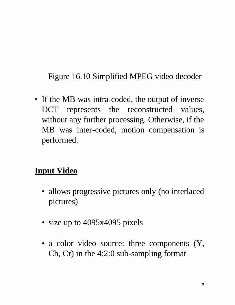
Figure 16.10 Simplified MPEG video decoder
• If the MB was intra-coded, the output of inverse DCT represents the reconstructed values, without any further processing. Otherwise, if the MB was inter-coded, motion compensation is performed.
Input Video • allows progressive pictures only (no interlaced
pictures) • size up to 4095x4095 pixels
• a color video source: three components (Y,
Cb, Cr) in the 4:2:0 sub-sampling format
10
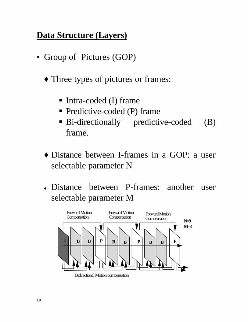
Data Structure (Layers) • Group of Pictures (GOP)
♦ Three types of pictures or frames:
§ Intra-coded (I) frame § Predictive-coded (P) frame § Bi-directionally predictive-coded (B)
frame.
♦ Distance between I-frames in a GOP: a user selectable parameter N
♦ Distance between P-frames: another user
selectable parameter M
I B B P B B P B B P
Forward MotionCompensation
Forward MotionCompensation
Forward MotionCompensation
Bidirectional Motion compensation
N=9M=3

11
Figure 16.1 A group of pictures of video sequence
• Slice § Each frame may be divided into slices
• Macroblock (MB) § Each slice consists of several MBs. § An MB: a 16 x 16 Y component and spatially
corresponding to 8 x 8 Cb and Cr components.
§ An MB has four luminance blocks and two
chrominance blocks (for 4:2:0 sampling format).
§ MB: The basic unit of adaptive quantization
and motion compensation.
• Blocks

12
§ Each block: 8 x 8 pixels over which the DCT operation is performed.
Table 16.1 Summary of important syntax of each layer
Name of layer Important syntax elements Sequence Picture size and frame rate
Bit rate and buffering requirement Programmable coding parameters
GOP Random access unit Time code
Picture Timing information (buffer fullness, temporal reference) Coding type (I, P or B)
Slice Intra-frame addressing information Coding re-initialization (error resilience)
MB Basic coding structure Coding mode Motion vectors Quantization
Block DCT coefficients
Inter- and Intra-frame Coding

13
• MV for each MB estimated from two original luminance pictures using a block-matching algorithm.
• Matching criterion: the minimum mean
absolute error (MAE)
• All MBs in I-frame coded in intra mode (no motion compensation).
• MBs in P and B-frames can be coded in
several modes.
Among the modes are intra-coded and inter-coded (with motion compensation).
Decision is made by mode selection, depending on values of prediction differences.
• Within each slice, MVs and DC values of
each MB are coded with DPCM coding. • Detailed specifications can be found in the
document [mpeg2].

14
Transmission Error Effect • An error within I frame data will be propagated
through all frames in GOP. • An error in a P-frame will affect the related P
and B frames. • B-frame errors will be isolated. Reordering of Input Frame Sequence • Needed since encoding order is different from
display order
• Example, if N = 12 and M = 3.
Display order 0 I
1 B
2 B
3 P
4 B
5 B
6 P
7 B
8 B
9 P
10 B
11 B
12 P
Encoding order 0 3 1 2 6 4 5 9 7 8 12 10 11
Coding type I P B B P B B P B B P B B
15
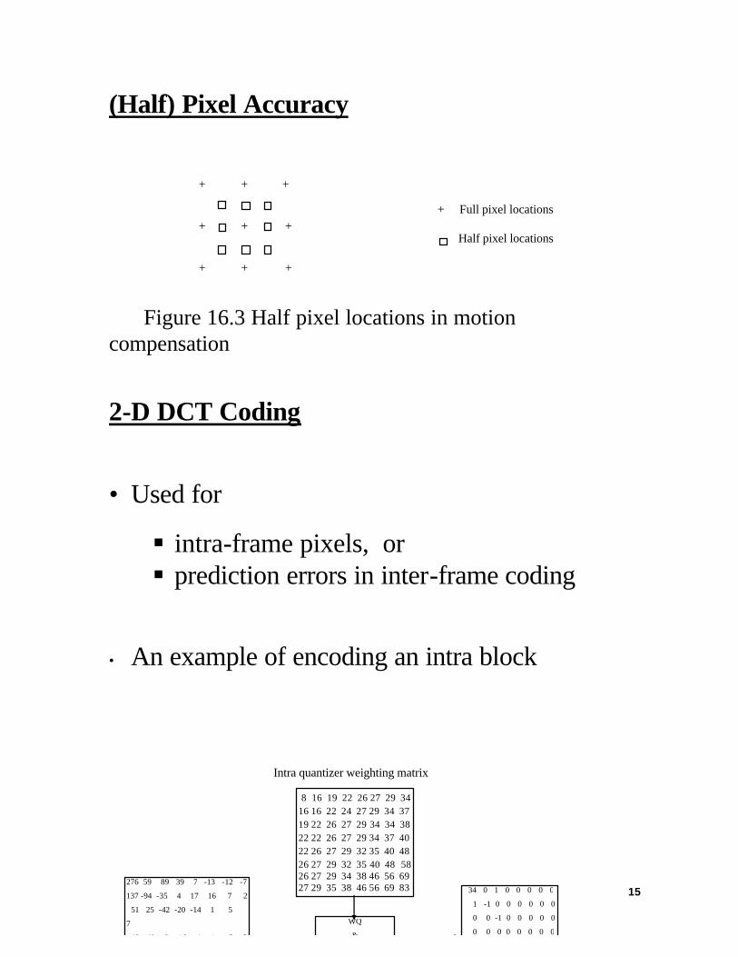
(Half) Pixel Accuracy
Figure 16.3 Half pixel locations in motion compensation
2-D DCT Coding
• Used for
§ intra-frame pixels, or § prediction errors in inter-frame coding
• An example of encoding an intra block
+ + + + + + + + +
+ Full pixel locations
Half pixel locations
276 59 89 39 7 -13 -12 -7
137 -94 -35 4 17 16 7 2
51 25 -42 -20 -14 1 5
7
-12 40 -8 -16 -4 -4 -5 -5
WQ
&
34 0 1 0 0 0 0 0
1 -1 0 0 0 0 0 0
0 0 -1 0 0 0 0 0
0 0 0 0 0 0 0 0
Intra quantizer weighting matrix
8 16 19 22 26 27 29 34 16 16 22 24 27 29 34 37 19 22 26 27 29 34 34 38 22 22 26 27 29 34 37 40 22 26 27 29 32 35 40 48 26 27 29 32 35 40 48 58 26 27 29 34 38 46 56 69 27 29 35 38 46 56 69 83
16
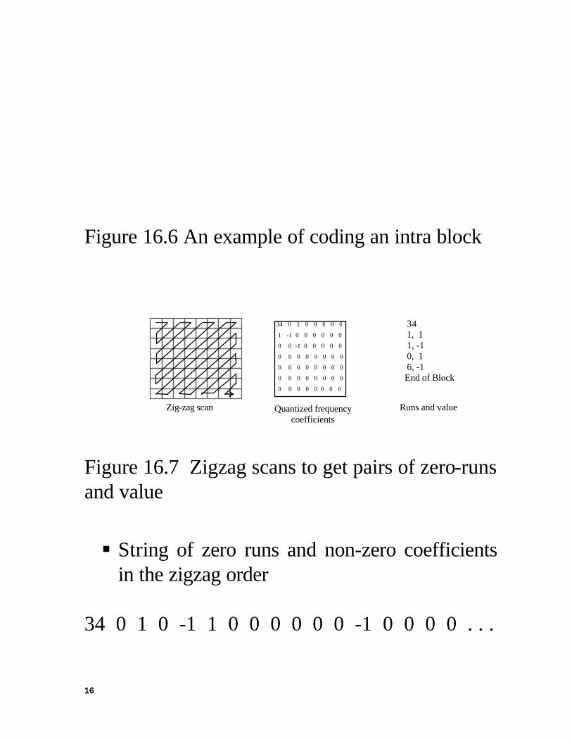
Figure 16.6 An example of coding an intra block
Figure 16.7 Zigzag scans to get pairs of zero-runs and value
§ String of zero runs and non-zero coefficients in the zigzag order
34 0 1 0 -1 1 0 0 0 0 0 0 -1 0 0 0 0 . . .
34 0 1 0 0 0 0 0
1 -1 0 0 0 0 0 0
0 0 -1 0 0 0 0 0
0 0 0 0 0 0 0 0
0 0 0 0 0 0 0 0
0 0 0 0 0 0 0 0
0 0 0 0 0 0 0 0
34 1, 1 1, -1 0, 1 6, -1 End of Block
Zig-zag scan Quantized frequency coefficients
Runs and value

17
§ After parsing we obtain the pairs of zero runs and values:
34 | 0 1 | 0 -1 | 1 | 0 0 0 0 0 0 -1 | 0 0 0 0 ... § These pairs are then Huffman coded.
Run/Value VLC (Variable length code) 34 1, 1 0110 1, -1 0111 0, 1 110 6, -1 0001011 End of Block 10 § VLC tables obtained by statistically
optimizing a large number of training video sequences.
• Same idea applied to code DC values, MCs and
prediction errors. MPEG-1 Video Compressed Bitstream

18
Figure 16.8 Description of layered structure of compressed bitstream
Figure 16.9 Picture layer data structure
Sequence Header Sequence data Sequence header Sequence data
Picture width Picture height Aspect ratio Bit rate Picture rate ...
GOP header Picture header Picture ... Picture header Picture
Temporal reference Picture type VBV delay ... Extension start code picture structure ...
Picture header Slice header Macroblock ... Macroblock Slice header Macroblock ...
Address Type Quantizer scale
Motion vectors Coded block pattern Block Block ...
Slice Macroblock
Bl Block
Picture

19
16.2.2 MPEG-2 Enhancements ♦ Basic coding structure: the same as MPEG-1 ü intra-frame and inter-frame DCT ü MC ü I-, P- and B-pictures
♦ Most important features of MPEG-2 includes:
• Field/frame prediction modes for supporting the interlaced video input
• Field/frame DCT coding syntax • Downloadable quantization matrix and
alternative scan order • Scalability extension Above: related to support interlaced material. Below: several non-compression enhancements

20
• Syntax to facilitate 3:2 pull-down in decoder • Pan and scan codes with 1/16 pixel resolution • Display flags indicating: chromaticity,
subcarrier amplitude and phase (for NTSC/PAL/SECAM source material)
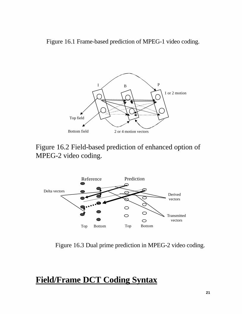
Field/frame prediction modes for supporting the interlaced video input
Top field
Bottom field
I B P
One or two motion vectors
One motion vector
21
Figure 16.1 Frame-based prediction of MPEG-1 video coding.
Figure 16.2 Field-based prediction of enhanced option of MPEG-2 video coding.
Reference Prediction
Figure 16.3 Dual prime prediction in MPEG-2 video coding.
Field/Frame DCT Coding Syntax
Top field
Bottom field
I B P
2 or 4 motion vectors
1 or 2 motion vector
Top Bottom Top Bottom
Transmitted vectors
Delta vectors Derived vectors

22
Field DCT Coding Luminance Macroblock Frame DCT Coding
Figure 16.4 Frame and field DCT for interlaced video.
Alternative Scan Order
Figure 16.15 Two zigzag scan methods for MPEG-2 video coding
Normal scan order Alternative scan order
DC DC

23
• Normal zigzag scan: used for MPEG-1 and as an option for MPEG-2.
• Alternative scan: not supported by MPEG-1
and an option for MPEG-2.
• For frame-type DCT of interlaced video, more energy may exist at the bottom part of the block, hence the run length coding may be better off with the alternative scan.
• In picture layer, there is a flag that can be set
for an alternative scan of DCT blocks.
Scalability • MPEG-2 has several scalable modes ü Spatial scalability ü Temporal scalability ü SNR scalability ü Data partitioning
• Merits:

24
ü allow a subset of bitstream to be decoded
into meaningful imagery. ü also, a useful tool for error resilience on
prioritized transmission media.
• Drawback: ü Some coding efficiency is lost due to extra
overhead. ü A moderate increase in complexity
♦ Spatial scalability § A single video source is split into: ü A base layer (lower spatial resolution)
and ü Enhancement layers (higher spatial
resolution).

25
e.g., an CCIR601 video can be down-sampled to SIF format with spatial filtering, which can serve as the base layer video.
§ Base layer can be coded with MPEG-1 or MPEG-2.
§ Enhancement layer must be coded by MPEG-
2 supported syntax.
§ A block diagram
MPEG encoder
Spatial filtering and down sampling
Decoder and spatial
up sampling
MPEG-2 compatible coder
HDTV input
SDTV Base layer bitstream
Enhancement layer bitstream
26
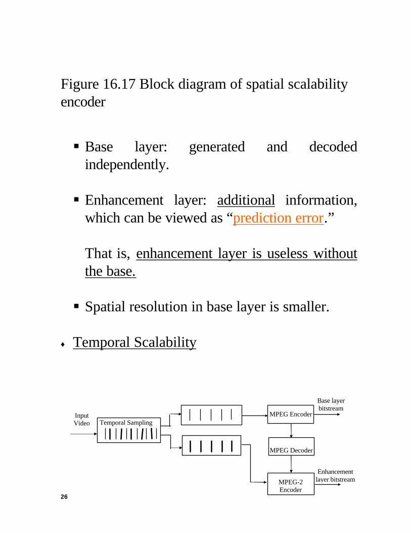
Figure 16.17 Block diagram of spatial scalability encoder
§ Base layer: generated and decoded independently.
§ Enhancement layer: additional information,
which can be viewed as “prediction error.”
That is, enhancement layer is useless without the base. § Spatial resolution in base layer is smaller.
♦ Temporal Scalability
Temporal Sampling MPEG Encoder
MPEG Decoder
MPEG-2 Encoder
Input Video
Base layer bitstream
Enhancement layer bitstream

27
Figure 16.18 Block diagram of temporal scalability
§ Base layer: low frame rate video § Enhancement layer: predictive coding § Spatial resolution: same in two layers
♦ SNR Scalability § Two layers: same spatial resolution and
temporal rate, but different qualities. § Low layer: low quality video § Low layer coded at a coarse quantization step
at 3-5 Mbps to provide NTSC/PAL/SECAM quality video for low capacity channel.
§ In enhancement layer, difference between
original and coarse quantized signals coded with a finer quantizer to generate an enhancement bitstream for high quality video applications.

28
16.3 MPEG-2 Video Encoding
16.3.1 Introduction
• MPEG video compression: a generic standard • Although a general coding methodology has
been recommended, how to generate high quality MPEG bit-streams is open.
§ flexibility in developing MPEG-specific
algorithms § leading to product differentiation on market
place. • To design a performance optimized MPEG-2
encoder system, several areas of research have to be considered.
§ Image pre-processing, motion estimation,
coding mode decisions, and rate control.

29
§ Aim: to minimize subjective distortion for a prescribed bit rate and operating delay constraint.
16.3.2 Pre-processing v Noise Filtering § Video signals corrupted by random and burst
noise, generated due to imperfections of scanning, transmission, or recording medium.
§ Filtering not only improves visual quality but
also increases coding performance. § Filtering each frame independently: spatial
filtering.
A variety of spatial filters available for noise reduction [cano 1983, katsaggelos 1991].
§ Filtering video sequence temporally along
motion trajectories using MC [sezan 1991].

30
§ MC spatio-temporal filtering performed better than spatial or MC temporal filtering alone [ozkan 1993].
v De-telecine Processing. § Movie material: shot at 24 progressive
frames/second § TV: at 30 frames/second § Conversion: made by a 3:2 pull-down process
(1st frame: repeated 3 times, 2nd frame: twice) ⇒ telecine source material § De-telecine process is necessary for detecting
and removing the redundant fields. (Rather than applying MPEG-2 encoding directly on 30 frames/second telecine material, one can remove redundant fields first and then encode 24 frames/second of unique material, thereby realizing higher coding quality at the same bit rate. The decoder can
31
simply reconstruct the redundant fields before presenting them.)
16.3.3. Advanced Motion Estimation (ME) ♦ ME using a reduced set of image data: § Reduction of search complexity by lowering
the precision of each sample does not appear to have been extensively studied.
§ Some experimental results have shown:
performance degradation of hierarchical ME is not serious when each layer in pyramid is limited to 6-bits/sample.
§ At 4-5 bits/sample the performance is
degraded 0.2 dB over full precision. ♦ Overlapped ME [94-04 pp.328]: § Motion compensated regions are overlapped
with each other.

32
§ A window function is used to determine the
weighting factors for each vector. § Improvements have been clearly identified for
low bit rate coding. § Has been adopted by H.263.
♦ Frequency domain ME: § An alternative to spatial-domain block
matching methods is to estimate motion vector in frequency domain through calculating cross-correlation [young 1993].
§ The new ME approach is proposed in DCT-
domain [koc 1998]. ü It has very low computational complexity
and is robust even in a noise environment. ü Moreover, the motion compensation
loop in the encoder is much simplified due

33
to replacing the IDCT out of the loop [koc 1998].
♦ Generalized block matching: § Encoded frame divided into triangular,
rectangular, or arbitrary quadrilateral patches. § Then search for the best matching triangular
or quadrilateral in the search frame under a given spatial transformation.
§ The choice of patch shape and spatial
transformation are mutual related.
ü Triangular patches offer sufficient degree of freedom with affine transformation, which has only six independent parameters.
ü Bilinear transform has eight free
parameters. Hence, it is suitable for use with rectangular or quadrilateral patches.

34
ü The generalized block matching is usually adaptively used only for those cases where standard block-matching is not satisfactory for avoiding imposed computational load.
16.4. Rate Control
16.4.1 Introduction of Rate Control ♦ From the view point of rate control, the
encoding can be classified into: § variable bit rate (VBR) coding § constant bit rate (CBR) coding.
• VBR coding: provides a constant picture quality
(perhaps, optimum) with variable coding bit rate • CBR coding: provides a constant bit rate with a
non-uniform picture quality.

35
• Rate control and buffer regulation: an important issue for both VBR and CBR applications.
• Rate control scheme has to be applicable to a
wide variety of sequences and bit rates. ♦ At GOP level, total available bits are allocated
among various picture types, taking into account constraints of the decoder buffer, so that perceived quality is balanced.
♦ Within each picture, the available bits are
allocated among MBs to maximize visual quality.
16.4.2 Rate Control of Test Model 5 (TM5) for MPEG-2 • Standard only defines syntax for decoding. • TM is an example of encoder, which may not be
optimal, it, however, can provide a compliant

36
compressed bitstream. Also, the TM served as a reference during development of the standard.
• TM5 rate control algorithm consists of three
steps to adapting the MB quantization parameter for controlling the bit rate.
1. Target bit allocation
• The first step of rate control.
• Before coding a picture, we need to estimate
total number of bits available for coding this picture.
• Estimation is based on several factors.
These include the picture type, buffer fullness and picture complexity.
• The estimation of picture complexity is
based on the number of bits and quantization parameter used for coding the same type previous picture in the GOP.

37
2. Rate control
• Within a picture the bits used for each MB is determined by the rate control algorithm.
• Then a quantizer step is derived from the
number of bits available for the MB to be coded.
• Before encoding the j-th macroblock, we
compute the fullness of the appropriate virtual buffers.
3. Adaptive quantization
• Adaptive quantization is the last step of the
TM5 rate control.
• Based on activity measure of the MB, the quantization step is adjusted according to activity measure discussed in Chapter 1.

38
16.5 Optimum Mode Decision
16.5.1 Problem Formation • The problem of determining the optimal MPEG
[mpeg2] coding strategy in terms of the selection of MB coding modes and quantizer scales.
• In TM [tm5], § Rate control operates independently from
coding mode selection for each MB. § Coding mode is decided based only upon the
energy of predictive residues. • Actually, two processes are intimately related to
each other and should be determined jointly in order to achieve optimal coding performance.
• Not an easy problem.

39
§ As an approximation, a near-optimum greedy algorithm can be developed.
§ Once the upper bound in performance is
calculated, it can be used to assess how well practical sub-optimum methods perform.
• Prior related works dealing with dependent
quantization for MPEG include the work done by Ramchandran [ramchandran 1994] and Lee [lee 94]. Not practical.
• More pragmatic solutions that can realistically
be implemented have been considered by Sun [sun 1997]. In this work, the major emphasis is not on the problem of bit allocation among I, P, and B frames; rather, the authors choose to utilize the frame level allocation method provided by the Test Model [tm5]. In this way, frame-level coding complexities are estimated from past frames without any forward pre-analysis knowledge of future frames. This type of analysis forms the most reasonable set of

40
assumptions for a practical real-time encoding system.
• Another method that extends the basic Test
Model idea to alter frame budgets heuristically in the case of scene changes, use of dynamic GOP size, and temporal masking effects can be found in [wang 1990]. These techniques also offer very effective and practical solutions for implementation. Given the chosen method for frame-level bit budget allocation, the focus of this section is to jointly optimizing macroblock coding modes and quantizers within each frame.
16.6 Statistical Multiplexing Operations on Multiple Program Encoding
• The strategies for statistical multiplexing
operation on the multiple program encoding • This topic is an extension of rate control into the
case of multiple program encoding.
41
• First, a background survey of general encoding
and multiplexing modes is reviewed. • Second, the specific algorithm used in some
current systems has been introduced, its shortcomings are addressed and possible amendments to the basic algorithm are described.
• Some potential research topics such as modeling
strategies and methods for solving the problem are proposed for investigation. These topics may be good research topics for the interested graduate student.
References [cano 1983] D. Cano and M. Benard, "3-D Kalman filtering of image sequences," in Image Sequence Processing and Dynamic Scene Analysis, T. S. Huang, Ed, Berlin: Springer, 1983, pp.563-579. [isnardi 1993] M. A. Isnardi, “Consumers seek easy to use products,” IEEE Spectrum, Jan. 1993, pp.64.
42
[katsaggelos 1991] A. K. Katsaggelos, R. P. Kleihorst, S. N. Efstratiadis and R. L. Lagendijk, "Adaptive image sequence noise filtering methods," Proceeding of SPIE Visual Communication and Image processing, 1991, Boston, MA, Nov. 10-13, 1991. [koc 1998] U. -V Koc and K. J. R. Liu, "DCT-based motion estimation," IEEE Trans. on Image Processing, Vol. 7, July 1998, pp.948-965. [lee 1994] J. Lee and B.W. Dickerson, "Temporally adaptive motion interpolation exploiting temporal masking in visual perception," IEEE Trans. on Image Proc. Vol. 3, No. 5, 526 Sept 1994, pp. 513-526. [mpeg1] ISO/IEC 11172, International Standard, 1992. [mpeg2] ISO/IEC 13818 MPEG-2 International Standard, Video Recommendation ITU-T H.262, Jan. 10, 1995. [ozkan 1993] M. K. Ozkan, M. I. Sezan and A. M. Tekalp, "Adaptive Motion-compensated filtering of noisy image sequences," IEEE Trans on Circuits and Systems for Video Technology, Vol. 3, No. 4, August 1993, pp.277-290. [ramchandran 1994] Kannan Ramchandran , Antonio Ortega and Martin Vetterli, “Bit Allocation for Dependent Quantization with Application to MPEG Video Coders”, IEEE Trans. on Image Proc. Vol. 3, No. 5, 526 Sept 1994, pp. 533-545. [sezan 1991] M. I. Sezan, M. K. Ozkan and S. V. Fogel, "Temporal adaptive filtering of noisy image sequences using a robust motion estimation algorithm," IEEE ICASSP, 1991, pp.2429-2432. [sun 1994] H. Sun, Sarnoff Internal technical report, May 1994. [tm5] MPEG-2 Test model 5, ISO-IEC/JTC1/SC29/WG11, April, 1993. [sun 1997] H. Sun, [wang 1995] L. Wang, "Rate control for MPEG-2 video coding", SPIE on Visual Communications and Image Processing, pp. 53-64, Taipei, Taiwan, May 1995. [young 1993] R. W. Young and N. G. Kingsbury, "Frequency-domain motion estimation using a complex lapped transform," IEEE Trans. on Image Processing, Vol. 2, No. 1, January 1993, pp2-17.