Diet Raspberry Pi - Adafruit Industries · Overview The Raspberry Pi finds itself in an...
21
Diet Raspberry Pi Created by Phillip Burgess Last updated on 2016-09-07 06:14:52 AM UTC
Transcript of Diet Raspberry Pi - Adafruit Industries · Overview The Raspberry Pi finds itself in an...

Diet Raspberry PiCreated by Phillip Burgess
Last updated on 2016-09-07 06:14:52 AM UTC

233567
1113171720
Guide Contents
Guide ContentsOverviewTools & PartsStepsRemove Port HousingsDesoldering PortsCleaning UpInstalling Low-Profile USB JacksFurther ModificationsShortening the GPIO HeaderRemoving Additional Parts
© Adafruit Industries https://learn.adafruit.com/diet-raspberry-pi Page 2 of 21

Overview
The Raspberry Pi finds itself in an ever-expanding gamut of project types…wearables,drones, internet of things and other embedded gizmos…and there are times when an extra-slim version of this already diminutive wonderputer would be just the thing.
Here we’ll show how to trim some fat from the Raspberry Pi Model B+. You’ll lose theEthernet port and at least two of the USB ports, so this is really suited only to projectswhere size or weight take priority over connectivity.
DISCLAIMER: performing these modifications can be really rough on the board…this caneasily go wrong and render the Pi inoperable. This is best attempted by experiencedhobbyists. And even then…Seriously. Don’t attempt this on your precious one and only board. Always mount a scratchmonkey.
Tools & PartsIn addition to a good soldering iron, you’ll need a solder sucker and some solderwick for cleanup. Flux (either the brush-on or the pen kind) makes wicking easier, but isn’tabsolutely essential for success. Other tools include flush diagonal
© Adafruit Industries https://learn.adafruit.com/diet-raspberry-pi Page 3 of 21

cutters, pliers and safety glasses.
If you have access to a vacuum desoldering tool or a hot air solder rework tool, thatmight be helpful, but isn’t a necessity…those are big-ticket tools.
You will also need one or two replacement single USB Type A jacks (http://adafru.it/e8l),depending how many ports you want.
Small pliers and/or tweezers and a Panavise or a “helping hands” tool may also proveuseful. Anti-static mat too, if you have one.
© Adafruit Industries https://learn.adafruit.com/diet-raspberry-pi Page 4 of 21

StepsBefore taking an iron to your Raspberry Pi, download and install an OS image on amicroSD card and confirm that the system boots successfully. If it refuses to run in thisstate, we can troubleshoot and replace the board if needed. This is your last chance…oncemodified, there’s no telling if a failure was from the factory or a result of your board work.
Physically altering the Raspberry Pi is a warranty-voiding operation. We cannot replace orrefund modified boards. Test it first!
Dismantling the Raspberry Pi is extra challenging, even if you have prior desolderingexperience. Lead-free solder requires higher temperatures, and this board’ssubstantial ground plane draws away a lot of heat. But apply too much heat and you’ll ripup traces or delaminate the board!
Lead-free desoldering is alreadytough, but a few points on theboard are particularlychallenging. They’re connectedto the ground plane, whichbecomes a big heat sink.
Be extra careful melting these…linger too long and the wholeboard gets uncomfortably hot!
The conversion process is made a little easier by just not trying to salvage the partsbeing removed! Don’t hesitate to clip leads, or completely dismantle themetal port housings. Anything to better access the area you’re trying to desolder. Let it go.
There is no One Right Way™ to do this. The process should be adapted to your ownparticular skills and tools on hand. Even with a wealth of tools, it’s still pretty time-consuming and may take a couple hours.
WEAR SAFETY GLASSES when clipping parts. Lots of sharp tiny bits are about to go
© Adafruit Industries https://learn.adafruit.com/diet-raspberry-pi Page 5 of 21

flying everywhere!
Remove Port Housings
Dismantling the metal housingsaround the Ethernet and USBports can help reduce the overallthermal mass when desoldering,and makes some pins easier toaccess. But they’re destoyed inthe process and can’t besalvaged.
If you go this route, watch outfor capacitors C97, C99 and
© Adafruit Industries https://learn.adafruit.com/diet-raspberry-pi Page 6 of 21

C100 when prying the backs offthe USB ports. Don’t shear themoff the board!
Desoldering Ports
A vise is essential. This leavesboth hands free…one for holding
© Adafruit Industries https://learn.adafruit.com/diet-raspberry-pi Page 7 of 21

a soldering iron, the other forprying and desoldering tools.Also, the board’s ground planecan get quite hot and shouldn’tbe handled.
Removing parts often requires arocking motion; heating one endwhile prying from the other,alternating sides. Cutting pinsflush with the surface of theboard reduces the amount ofrocking needed…they’ll clear thevias sooner.
© Adafruit Industries https://learn.adafruit.com/diet-raspberry-pi Page 8 of 21

Though I have a solder reflowtool that should, in theory, beable to heat all the pins forextracting the part…in practice Iwas having no luck, and wentback to my trusty soldering iron,heating, prying and rocking. Usewhatever you have and workswell for you.
© Adafruit Industries https://learn.adafruit.com/diet-raspberry-pi Page 9 of 21

That thing about lead-free beinghard to desolder? It was mosttroublesome with the Ethernetport LEDs, where the plastichousing would soften and deformbefore the solder would evenmelt. Fine then, let it deform, pryit up just enough to snip the legsof the LEDs. The remaining pinswere desoldered with the heat-pry-rock technique.
Eventually — boop! Freedom!Don’t worry about the remnantsleft on the board…we’ll clean thatup later.
The USB ports similarly requireda lot of grappling. Rather thantrying to desolder the pins andpry the housing off the board, thehousing was dismantled and thepins were clipped from thecomponent side, and theschrapnel will be cleaned uplater.
© Adafruit Industries https://learn.adafruit.com/diet-raspberry-pi Page 10 of 21

The sad remains of the ports arethen cleared. As each pin isheated from the underside, it’splucked out with tweezers fromthe component side.
Cleaning Up
After all the pins areremoved, most vias are stillplugged with solder. Use the
© Adafruit Industries https://learn.adafruit.com/diet-raspberry-pi Page 11 of 21
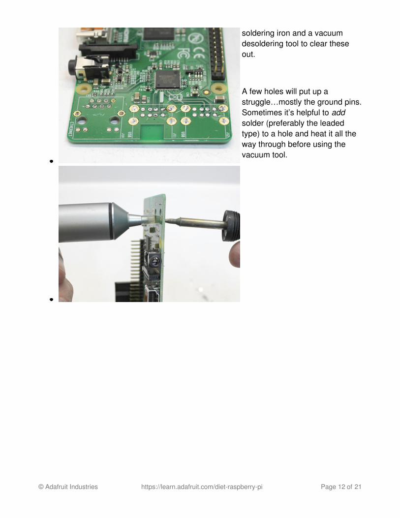
soldering iron and a vacuumdesoldering tool to clear theseout.
A few holes will put up astruggle…mostly the ground pins.Sometimes it’s helpful to addsolder (preferably the leadedtype) to a hole and heat it all theway through before using thevacuum tool.
© Adafruit Industries https://learn.adafruit.com/diet-raspberry-pi Page 12 of 21

The holes are clear, but there’sstill a lot of solder debris on theboard…this can bridge vias andcause mayhem, even if you’renot using the correspondingports.
Solder wick is heated under thetip of the soldering iron andrubbed across the areas toclean…this soaks up solder like apaper towel! Do this on bothsides of the board. Applyingliquid soldering flux first (eitherthe brush-on or pen applicatortype) makes this process a littlesmoother and cleaner.
You may need to revisit someholes with the solder-sucker.
© Adafruit Industries https://learn.adafruit.com/diet-raspberry-pi Page 13 of 21

Installing Low-Profile USB JacksBefore proceeding, you can optionally let the board cool off, insert a microSD card and testwhether it still boots. Without USB ports you won’t be able to connect a keyboard and shutdown cleanly, so don’t do this with a card containing irreplaceable data.
If the system won’t boot…or if it does boot, but the red power LED is flashing, disconnectpower and look over your desoldering work for any bridged connections, or conductivedetritus that may have been scattered on other parts of the board.
© Adafruit Industries https://learn.adafruit.com/diet-raspberry-pi Page 14 of 21

You can install one ortwo replacement USB ports,depending on your needs. Unlikethe old stacked ports, these aresingle-height, so two is themaximum.
These should pop right into theold spots. Use the outer row ofholes, closer to the board edge.The other row will remainunpopulated.
Flip the board over andsolder the four pins and twometal housing support tabs.Once the solder’s cooled, youcan trim these close to the boardso it sits flat.
Once it’s fully cooled, try attaching a monitor and booting the system from a microSD card.
© Adafruit Industries https://learn.adafruit.com/diet-raspberry-pi Page 15 of 21

If the transplant was a success, you should be able to connect a USB keyboard and log in.
The red “PWR” LED should be on steady. If it’s flashing, there’s an electrical short or adamaged component somewhere.
© Adafruit Industries https://learn.adafruit.com/diet-raspberry-pi Page 16 of 21

Further Modifications
Shortening the GPIO Header
With the single-height USBjack(s) installed, the GPIOheader is now the highest-profilepart on the board. This can beshortened slightly while retainingfull functionality…
© Adafruit Industries https://learn.adafruit.com/diet-raspberry-pi Page 17 of 21

The edge of the header’s plasticsupport can be lifted slightlyusing flush cutters. Be careful notto cut the pins!
You can then work along theedge with a small screwdriver topry off this piece.
Your mileage may vary. Withone Pi, the plastic support priedoff cleanly. With another, this partneed to be completely “nibbled”into dust!
© Adafruit Industries https://learn.adafruit.com/diet-raspberry-pi Page 18 of 21

Use a spare piece of single-rowpin header as a template fortrimming the GPIO pins. Wedgethis pin side down between theGPIO rows, then trim along theplastic edge.
When you’re done, the GPIOheader will be a couplemillimeters shorter, roughly in-line with the video connectors onthe opposite edge. Anythingplugged into this (ribbon cables,Pi HATs, etc.) will sit just a littlebit lower now.
© Adafruit Industries https://learn.adafruit.com/diet-raspberry-pi Page 19 of 21

Or, if you don’t anticipate usingthe GPIO header at all (or justneed a few pins and can wire tothem directly), it can becompletely desoldered andremoved.
Removing Additional PartsIf extreeeme weight saving is needed (e.g. for drones), many of the ports and jacks cansuccessfully be removed, as long the corresponding functionality is never again needed foryour application (there’s no going back with most of these surface-mount parts):
GPIO headerHDMI port
© Adafruit Industries https://learn.adafruit.com/diet-raspberry-pi Page 20 of 21

Composite video/audio portFPC display connectorCamera connectorMicro USB power connector (if regulated +5V is instead fed to the appropriate pins onthe GPIO header).
Most of these parts are about the same height, so there’s little point in removing a subsetas a space-saving measure. But for aerial applications, every gram counts…go nuts.
If all of the display options are removed, then the system can only be administeredremotely (e.g. ssh through WiFi). If all of the USB ports have also been removed, then theonly way to log directly into the system is with a serial console cable connected to theappropriate pins on the GPIO header.
Sometimes it’s easiest just to have a second, unmodified Raspberry Pi foradministration tasks. Move the microSD card to this system, boot and perform whateverconfiguration is necessary, then shut down and move the card back to the pared-downboard.
© Adafruit Industries Last Updated: 2016-09-07 06:14:51 AM UTC Page 21 of 21