Diagnosing Bad FEA Models - Siemens PLM Community · Stiffeners were meshed separate and a...
22
NEi Sensitive/Proprietary www.NEiSoftware.com Design, Analysis, and Simulation Diagnosing Bad FEA Models 6/26/2013
Transcript of Diagnosing Bad FEA Models - Siemens PLM Community · Stiffeners were meshed separate and a...

NEi Sensitive/Proprietary
www.NEiSoftware.com
Design, Analysis, and Simulation
Diagnosing Bad FEA Models
6/26/2013

NEi Sensitive/Proprietary
www.NEiSoftware.com
Design, Analysis, and Simulation
Example 1
6/26/2013
File: plate_bad.nas
Description:
Deck plating with stiffeners modeled as bars. Turn on thickness/Cross Section to
see stiffeners.
Error:
FATAL ERROR E5000: SINGULARITY DETECTED AT GRID 1462 COMPONENT 5
NEi Sensitive/Proprietary
www.NEiSoftware.com
Design, Analysis, and Simulation
Example 1
6/26/2013
Debug:
Run modal analysis – zero frequency modes with stiffeners flying around as well as
modes with the stiffeners clearly not connected to the plates

NEi Sensitive/Proprietary
www.NEiSoftware.com
Design, Analysis, and Simulation
Example 1
6/26/2013
Fix:
Run coincident node check and rerun.
Problem:
Stiffeners were meshed separate and a coincident node check was not performed.
NEi Sensitive/Proprietary
www.NEiSoftware.com
Design, Analysis, and Simulation
Example 2
6/26/2013
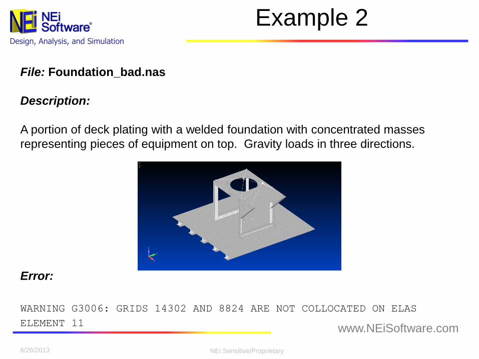
File: Foundation_bad.nas
Description:
A portion of deck plating with a welded foundation with concentrated masses
representing pieces of equipment on top. Gravity loads in three directions.
Error:
WARNING G3006: GRIDS 14302 AND 8824 ARE NOT COLLOCATED ON ELAS
ELEMENT 11

NEi Sensitive/Proprietary
www.NEiSoftware.com
Design, Analysis, and Simulation
Example 2
6/26/2013
Debug:
Run RBCHECKLEVEL to get output showing internal grounding.
WARNING G3033: RIGID-BODY STRAIN ENERGY CHECK FAILED IN ONE OR MORE
DIRECTIONS

NEi Sensitive/Proprietary
www.NEiSoftware.com
Design, Analysis, and Simulation
Example 2
6/26/2013
Fix:
Replace CELAS elements with CBUSH elements of the same stiffnesses.
Problem:
CELAS elements have finite length.
NEi Sensitive/Proprietary
www.NEiSoftware.com
Design, Analysis, and Simulation
Example 3
6/26/2013
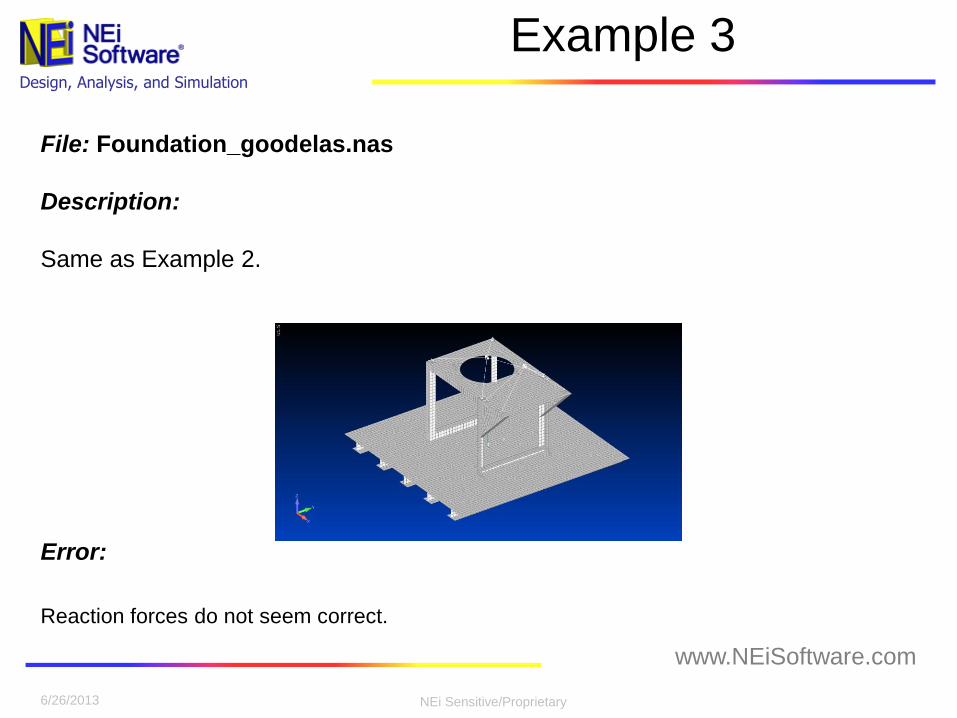
File: Foundation_goodelas.nas
Description:
Same as Example 2.
Error:
Reaction forces do not seem correct.
NEi Sensitive/Proprietary
www.NEiSoftware.com
Design, Analysis, and Simulation
Example 3
6/26/2013
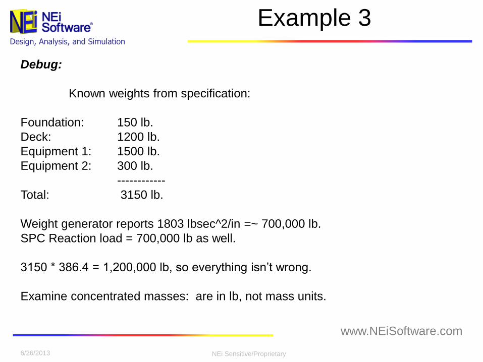
Debug:
Known weights from specification:
Foundation: 150 lb.
Deck: 1200 lb.
Equipment 1: 1500 lb.
Equipment 2: 300 lb.
------------
Total: 3150 lb.
Weight generator reports 1803 lbsec^2/in =~ 700,000 lb.
SPC Reaction load = 700,000 lb as well.
3150 * 386.4 = 1,200,000 lb, so everything isn’t wrong.
Examine concentrated masses: are in lb, not mass units.

NEi Sensitive/Proprietary
www.NEiSoftware.com
Design, Analysis, and Simulation
Example 3
6/26/2013
Fix:
Divide weights on CONM2 by 386.4
Problem:
Concentrated masses input in pounds, densities in lb-sec2/in
NEi Sensitive/Proprietary
www.NEiSoftware.com
Design, Analysis, and Simulation
Example 4
6/26/2013
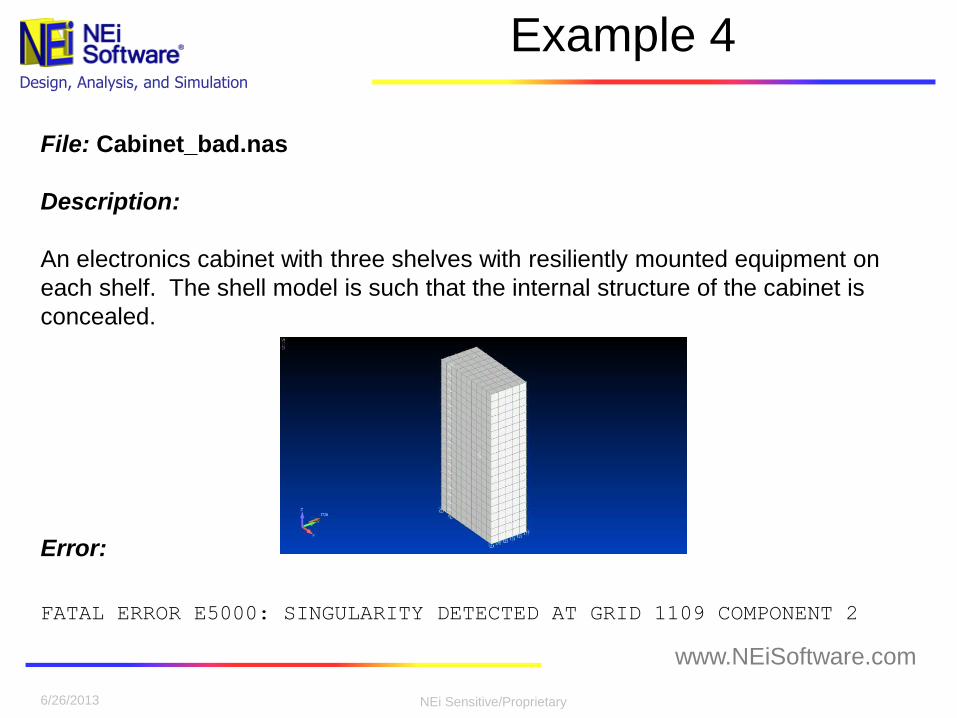
File: Cabinet_bad.nas
Description:
An electronics cabinet with three shelves with resiliently mounted equipment on
each shelf. The shell model is such that the internal structure of the cabinet is
concealed.
Error:
FATAL ERROR E5000: SINGULARITY DETECTED AT GRID 1109 COMPONENT 2

NEi Sensitive/Proprietary
www.NEiSoftware.com
Design, Analysis, and Simulation
Example 4
6/26/2013
Debug:
View model based on element properties.
Free-Edge check.
Look at the singular node – It is a corner of the lower plate. Turning node numbers
on will reveal two nodes there and on the other corners as well.
NEi Sensitive/Proprietary
www.NEiSoftware.com
Design, Analysis, and Simulation
Example 4
6/26/2013
Fix:
Run a coincident node check on the lower plate and the CBUSH elements.
Problem:
CBUSH elements were not attached to the lower plate. It had been re-meshed and
there were duplicate corner nodes

NEi Sensitive/Proprietary
www.NEiSoftware.com
Design, Analysis, and Simulation
Example 4a
6/26/2013 6/26/2013
File: Cabinet_bad.nas
Description:
Re-run previous model
Error:
FATAL ERROR E5000: SINGULARITY DETECTED AT GRID 1095 COMPONENT 2

NEi Sensitive/Proprietary
www.NEiSoftware.com
Design, Analysis, and Simulation
Example 4a
6/26/2013
Debug:
This one is one of the other masses.
Consider why it would be singular in the 2 direction (Y translation)
• No connections
• Bad RBE element
• No stiffness
Examination will reveal that the CBUSH elements are not duplicated on this mass.
RBE element is in DOF 1-6
Look at CBUSH elements themselves. They have no stiffness in the lateral
directions (only axial), hence the direction 2 singularity.
• DOF 1 is also singular
• All the CBUSH elements are similar

NEi Sensitive/Proprietary
www.NEiSoftware.com
Design, Analysis, and Simulation
Example 4a
6/26/2013
Fix:
Add lateral stiffness to the CBUSH elements.
Problem:
CBUSH elements had been considered for only vertical loads and only an axial
stiffness was included.
This arrangement may have run for the vertical loads, but not for the others. It is
always good modeling practice to include stiffness in all directions and not rely on
the FEA code to remove them.

NEi Sensitive/Proprietary
www.NEiSoftware.com
Design, Analysis, and Simulation
Example 5
6/26/2013
File: badtet_bad.nas
Description:
A mixed solid/shell model. Some of the solid nodes were moved to line up with the
shells.
Error:
No error, but GEOMCHECK flags a number of these elements as having bad EPLR and
EPAD values.

NEi Sensitive/Proprietary
www.NEiSoftware.com
Design, Analysis, and Simulation
Example 5
6/26/2013
Debug:
Examine elements identified but GEOMCHECK as having problems
Midside nodes are not approximately midside in these elements
NEi Sensitive/Proprietary
www.NEiSoftware.com
Design, Analysis, and Simulation
Example 5
6/26/2013
Fix:
Realign midside nodes that are out of place.
• Manually using FEMAP – Modify > Move To > Node using “Between”” method
• Automatically using PARAM,ALIGNEDGENODE,ON and PARAM,
EDGENODETOL,0.0
• TRSLMODLDATA,ON will produce a BDF file with the nodes realigned
Problem:
The nodes on the tet elements had been moved to line up with the shell elements,
but the corresponding midside nodes had not.
NEi Sensitive/Proprietary
www.NEiSoftware.com
Design, Analysis, and Simulation
Example 6
6/26/2013
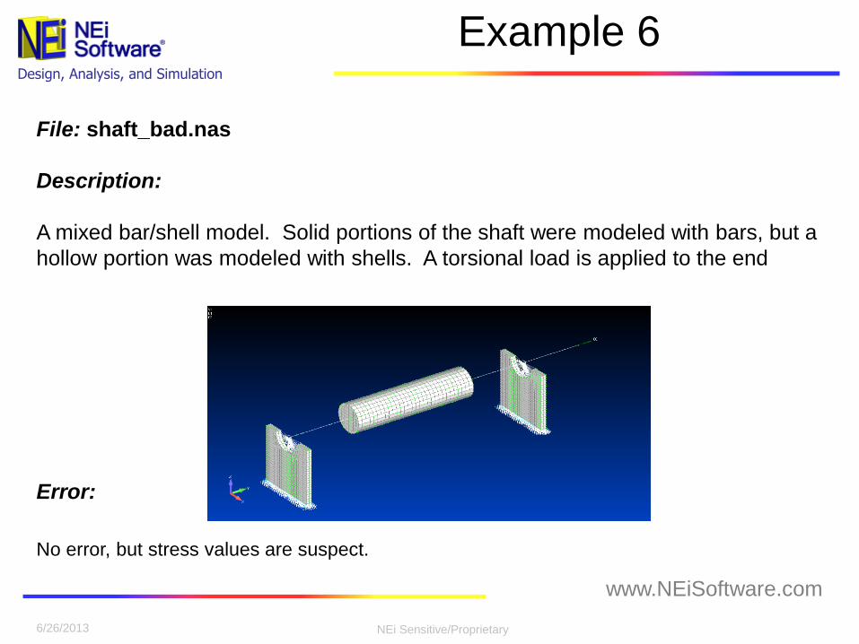
File: shaft_bad.nas
Description:
A mixed bar/shell model. Solid portions of the shaft were modeled with bars, but a
hollow portion was modeled with shells. A torsional load is applied to the end
Error:
No error, but stress values are suspect.
NEi Sensitive/Proprietary
www.NEiSoftware.com
Design, Analysis, and Simulation
Example 6
6/26/2013
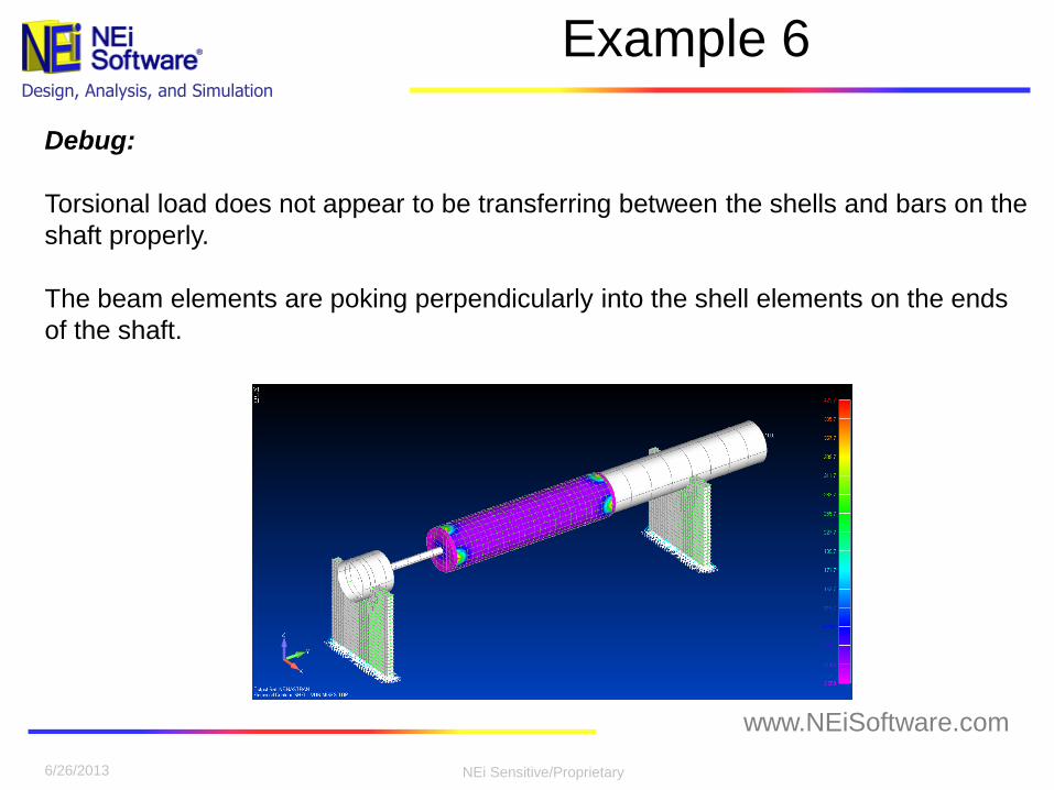
Debug:
Torsional load does not appear to be transferring between the shells and bars on the
shaft properly.
The beam elements are poking perpendicularly into the shell elements on the ends
of the shaft.
NEi Sensitive/Proprietary
www.NEiSoftware.com
Design, Analysis, and Simulation
Example 6
6/26/2013
Fix:
Transfer the torsional loads between the shells and beams with rigid elements.
RBE3 elements are recommended as they do not stiffen the structure.
Problem:
CQUAD4 elements are singular in the normal rotational (drilling) degree of freedom.
Even CQUADR elements have an artificial stiffness in that direction. It is best to
spread the load out to the actual contact area using RBE3 elements to transfer the
translations of the surrounding nodes into a rotation on the bar element.