
Devt of Tube Repair Techniques for HR Steam Generators
140
Development of Tube Repair Techniques for Heat Recovery Steam Generators Supporting Stress Analyses, Code Interpretation, and Internal Tube Repair 1010512 Effective December 6, 2006, this report has been made publicly available in accordance with Section 734.3(b)(3) and published in accordance with Section 734.7 of the U.S. Export Administration Regulations. As a result of this publication, t his report is subje ct to only copyright protection and does not require any license agreement from EPRI . This notice supersedes the export control restrictions and any proprietary licensed material notices embedded in the document prior to publication.
-
Upload
jans-fernandez -
Category
Documents
-
view
218 -
download
0
Transcript of Devt of Tube Repair Techniques for HR Steam Generators
7/29/2019 Devt of Tube Repair Techniques for HR Steam Generators
http://slidepdf.com/reader/full/devt-of-tube-repair-techniques-for-hr-steam-generators 1/140
Development of Tube Repair Techniques forHeat Recovery Steam Generators
Supporting Stress Analyses, Code Interpretation, and Internal Tube Repair
1010512
Effective December 6, 2006, this report has been made publicly available in accordance
with Section 734.3(b)(3) and published in accordance with Section 734.7 of the U.S. Export
Administration Regulations. As a result of this publication, this report is subject to only
copyright protection and does not require any license agreement from EPRI. This notice
supersedes the export control restrictions and any proprietary licensed material notices
embedded in the document prior to publication.

7/29/2019 Devt of Tube Repair Techniques for HR Steam Generators
http://slidepdf.com/reader/full/devt-of-tube-repair-techniques-for-hr-steam-generators 2/140

7/29/2019 Devt of Tube Repair Techniques for HR Steam Generators
http://slidepdf.com/reader/full/devt-of-tube-repair-techniques-for-hr-steam-generators 3/140
EPRI Project ManagerD. Gandy
ELECTRIC POWER RESEARCH INSTITUTE3420 Hillview Avenue, Palo Alto, California 94304-1395 ▪ PO Box 10412, Palo Alto, California 94303-0813 ▪ USA
800.313.3774 ▪ 650.855.2121 ▪ [email protected] ▪ www.epri.com
Development of Tube RepairTechniques for Heat Recovery
Steam GeneratorsSupporting Stress Analyses, Code Interpretation,and Internal Tube Repair
1010512
Technical Update, March 2006

7/29/2019 Devt of Tube Repair Techniques for HR Steam Generators
http://slidepdf.com/reader/full/devt-of-tube-repair-techniques-for-hr-steam-generators 4/140
DISCLAIMER OF WARRANTIES AND LIMITATION OF LIABILITIES
THIS DOCUMENT WAS PREPARED BY THE ORGANIZATION(S) NAMED BELOW AS ANACCOUNT OF WORK SPONSORED OR COSPONSORED BY THE ELECTRIC POWER RESEARCHINSTITUTE, INC. (EPRI). NEITHER EPRI, ANY MEMBER OF EPRI, ANY COSPONSOR, THEORGANIZATION(S) BELOW, NOR ANY PERSON ACTING ON BEHALF OF ANY OF THEM:
(A) MAKES ANY WARRANTY OR REPRESENTATION WHATSOEVER, EXPRESS OR IMPLIED, (I)WITH RESPECT TO THE USE OF ANY INFORMATION, APPARATUS, METHOD, PROCESS, ORSIMILAR ITEM DISCLOSED IN THIS DOCUMENT, INCLUDING MERCHANTABILITY AND FITNESSFOR A PARTICULAR PURPOSE, OR (II) THAT SUCH USE DOES NOT INFRINGE ON ORINTERFERE WITH PRIVATELY OWNED RIGHTS, INCLUDING ANY PARTY'S INTELLECTUALPROPERTY, OR (III) THAT THIS DOCUMENT IS SUITABLE TO ANY PARTICULAR USER'SCIRCUMSTANCE; OR
(B) ASSUMES RESPONSIBILITY FOR ANY DAMAGES OR OTHER LIABILITY WHATSOEVER(INCLUDING ANY CONSEQUENTIAL DAMAGES, EVEN IF EPRI OR ANY EPRI REPRESENTATIVEHAS BEEN ADVISED OF THE POSSIBILITY OF SUCH DAMAGES) RESULTING FROM YOURSELECTION OR USE OF THIS DOCUMENT OR ANY INFORMATION, APPARATUS, METHOD,PROCESS, OR SIMILAR ITEM DISCLOSED IN THIS DOCUMENT.
ORGANIZATION(S) THAT PREPARED THIS DOCUMENT
Electric Power Research Institute (EPRI)
Structural Integrity Associates
NOTEFor further information about EPRI, call the EPRI Customer Assistance Center at (800) 313-3774 oremail [email protected]
Electric Power Research Institute and EPRI are registered service marks of the Electric PowerResearch Institute, Inc.
Copyright © 2006 Electric Power Research Institute, Inc. All rights reserved.
7/29/2019 Devt of Tube Repair Techniques for HR Steam Generators
http://slidepdf.com/reader/full/devt-of-tube-repair-techniques-for-hr-steam-generators 5/140
CITATIONS
This report was prepared by
Electric Power Research Institute (EPRI)NDE Center1300 W.T. Harris Blvd.Charlotte, NC 28262
Principal Investigator
D. Gandy
Structural Integrity Associates3500 Massillon RdSuite 420Uniontown, OH 44685
Principal InvestigatorsE. JonesM. Berasi
This report describes research sponsored by EPRI.
The report is a corporate document that should be cited in the literature in the following manner:
Development of Tube Repair Techniques for Heat Recovery Steam Generators: Supporting
Stress Analyses, Code Interpretation, and Internal Tube Repair. EPRI, Palo Alto, CA: 2006.1010512.
iii

7/29/2019 Devt of Tube Repair Techniques for HR Steam Generators
http://slidepdf.com/reader/full/devt-of-tube-repair-techniques-for-hr-steam-generators 6/140
7/29/2019 Devt of Tube Repair Techniques for HR Steam Generators
http://slidepdf.com/reader/full/devt-of-tube-repair-techniques-for-hr-steam-generators 7/140
PRODUCT DESCRIPTION
This report describes the results of two strategies for repair of heat recovery steam generators.The first few sections of this report provide supporting information for the tube-to-headerattachment repair described in EPRI report 1010441. The remainder of the report describes anew repair strategy that is to get underway in early 2006 that looks to address tube repair fromthe inside diameter of a tube.
Results and FindingsThe methodology and results of a finite element stress analyses performed on four configurationsof Heat Recovery Steam Generator (HRSG) header-to-tube attachments is described herein.These analyses were performed to compare stress levels in the original method of attachment tothose resulting from 3 alternative repair options designed to remove service-related cracking orother defects in the attachment weld. The repair options evaluated included two partialpenetration welds and one full penetration weld. Stresses due to internal pressure and externaltube bending loads were evaluated. For the two types of analysis completed in this study(internal pressure and unit bending moment), the original configuration generally showed higherstress levels than those found in the repair options. The full penetration repair weld option hadthe lowest stress levels.
Challenges and ObjectivesThis analysis (and the complete EPRI study on this matter) is important to all HRSG plantoperators as headers in these units have shown a propensity for failure at the header-to-tubeattachment weld during service. Furthermore, limited access typically associated with theseheaders generally precludes the use of traditional weld repairs made from the external surface of the header. As a result, EPRI has developed an innovative repair method performed from theinside of the header. The stress analysis of this report was subsequently important to demonstratethat this repair weld geometry would not introduce operating stresses greater than those of theoriginal geometry.
Applications, Values, and Use
This analysis is one part of the ongoing EPRI study into repair options for HRSG header-to-tubeweld.
v
7/29/2019 Devt of Tube Repair Techniques for HR Steam Generators
http://slidepdf.com/reader/full/devt-of-tube-repair-techniques-for-hr-steam-generators 8/140
EPRI PerspectiveThis report provides the supporting stress analysis data for performing HRSG attachment repairsfrom the inside diameter of a header. Utilizing this information, along with the repair approachdocumented in EPRI Report 1010441, EPRI approached the National Board in early 2006 andgained acceptance of the new HRSG header-to-tube weld repair approach. With this in hand,
utilities can now utilize the new repair approach to significantly reduce repair time when header-to-tube attachment cracking is identified. Furthermore, unnecessary removal and subsequentrepair of undamaged tubes to gain access to the damaged attachment area can be eliminatedaltogether.
ApproachUsing ANSYS 9.0 finite element software, a separate model for four different weldconfigurations was created and boundary conditions to simulate internal pressure and bendingmoment loads were applied. The results of this analysis were then presented to the NationalBoard, along with a discussion of the overall header-to-tube attachment repair approach. Basedon information, an “Interpretation” was provided by the National Board which enables utilities to
now utilized the repair technology.
KeywordsHRSG headerStress analysisStub tube attachmentfull penetrationPartial penetration
vi
7/29/2019 Devt of Tube Repair Techniques for HR Steam Generators
http://slidepdf.com/reader/full/devt-of-tube-repair-techniques-for-hr-steam-generators 9/140
CONTENTS
1 INTRODUCTION ....................................................................................................................1-1 2 DESIGN INPUTS....................................................................................................................2-1
Geometry ..............................................................................................................................2-1 Material Properties ................................................................................................................2-5 Loads ....................................................................................................................................2-5
Internal Pressure Boundary Conditions............................................................................2-5 Bending Moment Boundary Conditions ............................................................................2-5
3 RESULTS ...............................................................................................................................3-1 Internal Pressure Application Results ...................................................................................3-1 Bending Moment Application Results....................................................................................3-1 Conclusions and Recommendations.....................................................................................3-3
4 NATIONAL BOARD INTERPRETATION 04-15 ....................................................................4-5
5 INTERNAL TUBE REPAIR ....................................................................................................5-7 A APPENDIX............................................................................................................................ A-1
Original Configuration Pressure Run Images....................................................................... A-1 Partial Penetration (0.225” Weld Depth) Pressure Run Images......................................... A-13 Partial Penetration (0.243” Weld Depth) Pressure Run Images......................................... A-25 Full Penetration Pressure Run Images .............................................................................. A-37
B APPENDIX............................................................................................................................ B-1 Original Configuration Bending Moment Analysis Images ................................................... B-1 Partial Penetration (0.225” Weld Depth) Bending Moment Analysis Images..................... B-15 Partial Penetration (0.243” Weld Depth) Bending Moment Analysis Images..................... B-29 Full Penetration Bending Moment Analysis Images........................................................... B-43
vii

7/29/2019 Devt of Tube Repair Techniques for HR Steam Generators
http://slidepdf.com/reader/full/devt-of-tube-repair-techniques-for-hr-steam-generators 10/140
7/29/2019 Devt of Tube Repair Techniques for HR Steam Generators
http://slidepdf.com/reader/full/devt-of-tube-repair-techniques-for-hr-steam-generators 11/140
LIST OF FIGURES
Figure 2-1 Original Configuration 2-D Geometry (Side View)....................................................2-2 Figure 2-2 Partial Penetration (0.243” Weld Depth) 2-D Geometry (Side View)........................2-3 Figure 2-3 Partial Penetration (0.225” Weld Depth) 2-D Geometry (Side View)........................2-4 Figure 2-4 View of Applied Pressure Loads...............................................................................2-6 Figure 2-5 View of Applied Forces for Bending Moment Analysis .............................................2-7 Figure 4-1 Interpretation 04-15 Part RD-2060 Utilizing a Flush Patch to Gain Access
Window in Pressure Retaining Items. ......................................................................4-6 Figure A-1 Header Hoop Stress................................................................................................ A-1 Figure A-2 Header Hoop Stress................................................................................................ A-2 Figure A-3 Header Hoop Stress................................................................................................ A-3 Figure A-4 Header Axial Stress ................................................................................................ A-4 Figure A-5 Header Axial Stress ................................................................................................ A-5 Figure A-6 Header Axial Stress ................................................................................................ A-6 Figure A-7 1
stPrincipal Stress................................................................................................... A-7
Figure A-8 1st
Principal Stress................................................................................................... A-8 Figure A-9 1
stPrincipal Stress................................................................................................... A-9
Figure A-10 Stress Intensity.................................................................................................... A-10 Figure A-11 Stress Intensity.................................................................................................... A-11 Figure A-12 Stress Intensity.................................................................................................... A-12 Figure A-13 Header Hoop Stress............................................................................................ A-13 Figure A-14 Header Hoop Stress............................................................................................ A-14 Figure A-15 Header Hoop Stress............................................................................................ A-15 Figure A-16 Header Axial Stress ............................................................................................ A-16 Figure A-17 Header Axial Stress ............................................................................................ A-17 Figure A-18 Header Axial Stress ............................................................................................ A-18 Figure A-19 1
st
Principal Stress............................................................................................... A-19 Figure A-20 1
stPrincipal Stress............................................................................................... A-20
Figure A-21 1st
Principal Stress............................................................................................... A-21 Figure A-22 Stress Intensity.................................................................................................... A-22 Figure A-23 Stress Intensity.................................................................................................... A-23 Figure A-24 Stress Intensity.................................................................................................... A-24 Figure A-25 Header Hoop Stress............................................................................................ A-25
ix
7/29/2019 Devt of Tube Repair Techniques for HR Steam Generators
http://slidepdf.com/reader/full/devt-of-tube-repair-techniques-for-hr-steam-generators 12/140
Figure A-26 Header Hoop Stress............................................................................................ A-26 Figure A-27 Header Hoop Stress............................................................................................ A-27 Figure A-28 Header Axial Stress ............................................................................................ A-28 Figure A-29 Header Axial Stress ............................................................................................ A-29 Figure A-30 Header Axial Stress ............................................................................................ A-30 Figure A-31 1
stPrincipal Stress............................................................................................... A-31
Figure A-32 1st
Principal Stress............................................................................................... A-32 Figure A-33 1
stPrincipal Stress............................................................................................... A-33
Figure A-34 Stress Intensity.................................................................................................... A-34 Figure A-35 Stress Intensity.................................................................................................... A-35 Figure A-36 Stress Intensity.................................................................................................... A-36 Figure A-37 Header Hoop Stress............................................................................................ A-37 Figure A-38 Header Hoop Stress............................................................................................ A-38 Figure A-39 Header Hoop Stress............................................................................................ A-39 Figure A-40 Header Axial Stress ............................................................................................ A-40 Figure A-41 Header Axial Stress ............................................................................................ A-41 Figure A-42 Header Axial Stress ............................................................................................ A-42 Figure A-43 1
stPrincipal Stress............................................................................................... A-43
Figure A-44 1st
Principal Stress............................................................................................... A-44 Figure A-45 1
stPrincipal Stress............................................................................................... A-45
Figure A-46 Stress Intensity.................................................................................................... A-46 Figure A-47 Stress Intensity.................................................................................................... A-47 Figure A-48 Stress Intensity.................................................................................................... A-48 Figure B-1 Header Hoop Stress................................................................................................ B-1 Figure B-2 Header Hoop Stress................................................................................................ B-2 Figure B-3 Header Hoop Stress................................................................................................ B-3 Figure B-4 1
stPrincipal Stress................................................................................................... B-4
Figure B-5 1st
Principal Stress................................................................................................... B-5 Figure B-6 1
stPrincipal Stress................................................................................................... B-6
Figure B-7 Stress Intensity........................................................................................................ B-7 Figure B-8 Stress Intensity........................................................................................................ B-8 Figure B-9 Stress Intensity........................................................................................................ B-9 Figure B-10 Tube Axial Stress ................................................................................................ B-10 Figure B-11 Tube Axial Stress ................................................................................................ B-11 Figure B-12 Tube Axial Stress ................................................................................................ B-12 Figure B-13 Tube Axial Stress ................................................................................................ B-13 Figure B-14 Tube Hoop Stress ............................................................................................... B-14 Figure B-15 Header Hoop Stress............................................................................................ B-15 Figure B-16 Header Hoop Stress............................................................................................ B-16 x
7/29/2019 Devt of Tube Repair Techniques for HR Steam Generators
http://slidepdf.com/reader/full/devt-of-tube-repair-techniques-for-hr-steam-generators 13/140
Figure B-17 Header Hoop Stres ............................................................................................. B-17 Figure B-18 1
stPrincipal Stress............................................................................................... B-18
Figure B-19 1st
Principal Stress............................................................................................... B-19 Figure B-20 1
stPrincipal Stress............................................................................................... B-20
Figure B-21 Stress Intensity.................................................................................................... B-21 Figure B-22 Stress Intensity.................................................................................................... B-22 Figure B-23 Stress Intensity.................................................................................................... B-23 Figure B-24 Tube Axial Stress ................................................................................................ B-24 Figure B-25 Tube Axial Stress ................................................................................................ B-25 Figure B-26 Tube Axial Stress ................................................................................................ B-26 Figure B-27 Tube Axial Stress ................................................................................................ B-27 Figure B-28 Tube Hoop Stress ............................................................................................... B-28 Figure B-29 Header Hoop Stress............................................................................................ B-29 Figure B-30 Header Hoop Stress............................................................................................ B-30 Figure B-31 Header Hoop Stress............................................................................................ B-31 Figure B-32 1
stPrincipal Stress............................................................................................... B-32
Figure B-33 1st
Principal Stress............................................................................................... B-33 Figure B-34 1
stPrincipal Stress............................................................................................... B-34
Figure B-35 Stress Intensity.................................................................................................... B-35 Figure B-36 Stress Intensity.................................................................................................... B-36 Figure B-37 Stress Intensity.................................................................................................... B-37 Figure B-38 Tube Axial Stress ................................................................................................ B-38 Figure B-39 Tube Axial Stress ................................................................................................ B-39 Figure B-40 Tube Axial Stress ................................................................................................ B-40 Figure B-41 Tube Axial Stress ................................................................................................ B-41 Figure B-42 Tube Hoop Stress ............................................................................................... B-42 Figure B-43 Header Hoop Stress............................................................................................ B-43 Figure B-44 Header Hoop Stress............................................................................................ B-44 Figure B-45 Header Hoop Stress............................................................................................ B-45 Figure B-46 1
STPrincipal Stress.............................................................................................. B-46
Figure B-47 1ST
Principal Stress.............................................................................................. B-47 Figure B-48 1
STPrincipal Stress.............................................................................................. B-48
Figure B-49 Stress Intensity.................................................................................................... B-49 Figure B-50 Stress Intensity.................................................................................................... B-50 Figure B-51 Stress Intensity.................................................................................................... B-51 Figure B-52 Tube Axial Stress ................................................................................................ B-52 Figure B-53 Tube Axial Stress ................................................................................................ B-53 Figure B-54 Tube Axial Stress ................................................................................................ B-54
xi

7/29/2019 Devt of Tube Repair Techniques for HR Steam Generators
http://slidepdf.com/reader/full/devt-of-tube-repair-techniques-for-hr-steam-generators 14/140
xii

7/29/2019 Devt of Tube Repair Techniques for HR Steam Generators
http://slidepdf.com/reader/full/devt-of-tube-repair-techniques-for-hr-steam-generators 15/140
LIST OF TABLES
Table 2-1 Material Properties for P91 Material at 1000ºF..........................................................2-5 Table 3-1 Maximum and Minimum Stresses for Internal Pressure Analysis..............................3-2 Table 3-2 Maximum and Minimum Stresses for Bending Moment Analysis..............................3-3
xiii

7/29/2019 Devt of Tube Repair Techniques for HR Steam Generators
http://slidepdf.com/reader/full/devt-of-tube-repair-techniques-for-hr-steam-generators 16/140
7/29/2019 Devt of Tube Repair Techniques for HR Steam Generators
http://slidepdf.com/reader/full/devt-of-tube-repair-techniques-for-hr-steam-generators 17/140
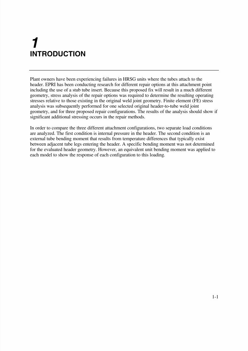
1 INTRODUCTION
Plant owners have been experiencing failures in HRSG units where the tubes attach to theheader. EPRI has been conducting research for different repair options at this attachment pointincluding the use of a stub tube insert. Because this proposed fix will result in a much differentgeometry, stress analysis of the repair options was required to determine the resulting operatingstresses relative to those existing in the original weld joint geometry. Finite element (FE) stressanalysis was subsequently performed for one selected original header-to-tube weld jointgeometry, and for three proposed repair configurations. The results of the analysis should show if significant additional stressing occurs in the repair methods.
In order to compare the three different attachment configurations, two separate load conditionsare analyzed. The first condition is internal pressure in the header. The second condition is anexternal tube bending moment that results from temperature differences that typically existbetween adjacent tube legs entering the header. A specific bending moment was not determinedfor the evaluated header geometry. However, an equivalent unit bending moment was applied toeach model to show the response of each configuration to this loading.
1-1

7/29/2019 Devt of Tube Repair Techniques for HR Steam Generators
http://slidepdf.com/reader/full/devt-of-tube-repair-techniques-for-hr-steam-generators 18/140

7/29/2019 Devt of Tube Repair Techniques for HR Steam Generators
http://slidepdf.com/reader/full/devt-of-tube-repair-techniques-for-hr-steam-generators 19/140
2-1
2 DESIGN INPUTS
Geometry
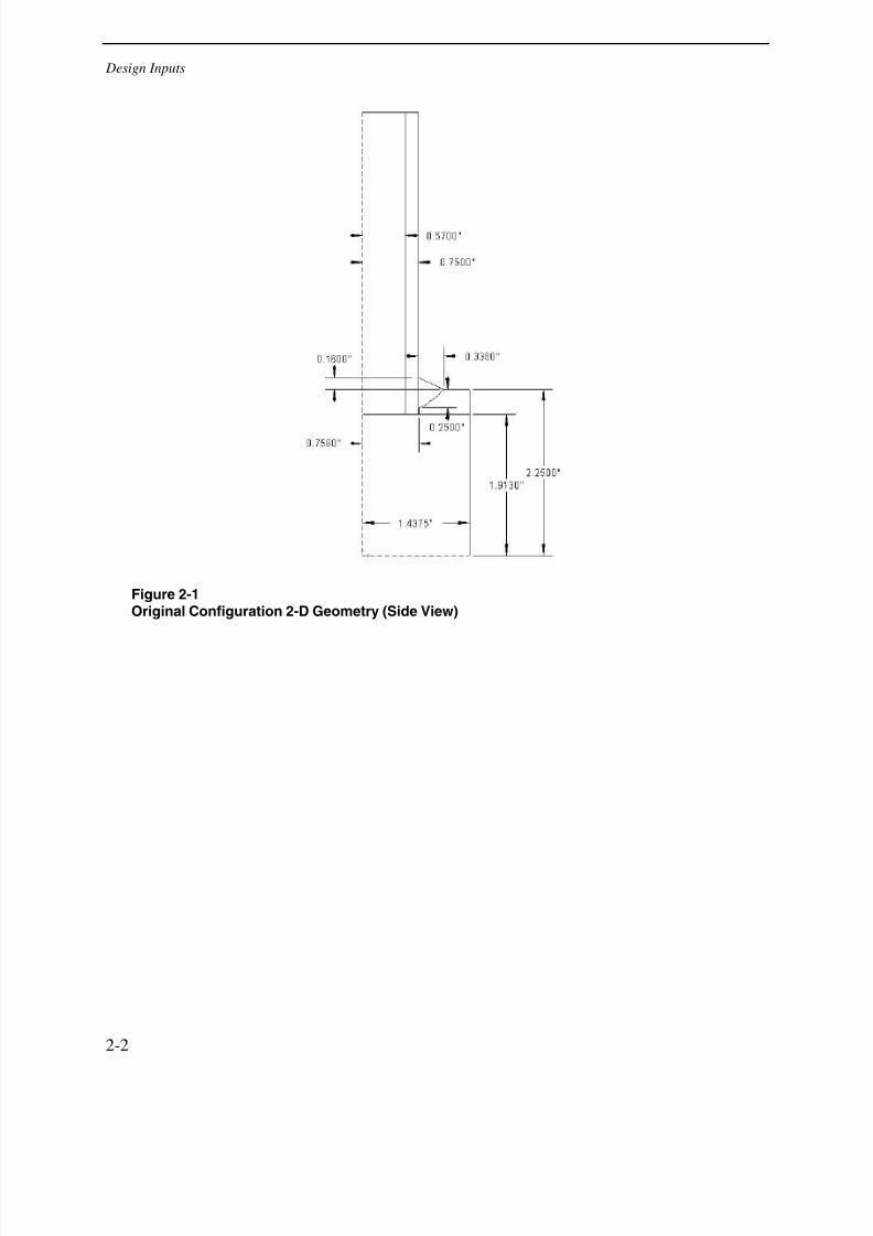
Four separate FE models were evaluated for this investigation, representing the original tube-to-header weld configuration, one full penetration weld repair, and two alternative partialpenetration repairs. Figures 2-1 through 2-3 show 2-dimensional sketches of each geometry.Note that the two partial penetration configurations differ only with respect to the depth of theweld and corresponding depth of the un-fused area in the weld joint. It is also noted that because
of the curvature of the header, the weld depth was held constant around the circumference of thetube. For the full penetration configuration, the weld depth is considered to be the full thicknessof the header.
The FE models for the pressure runs depict one-fourth of a tube cross-section and one-half of theheader cross-section for one row of tubes. The models are restricted in the necessary planes sothat further modeling of symmetrical sides of the header/tube is not necessary to apply thepressure loads and retrieve accurate results. For the bending moment analysis, however, it wasnecessary to mirror copy the model to create a full header cross-section and half cross-section of a tube. This change was necessary to correctly apply the forces that mimic a bending moment.
7/29/2019 Devt of Tube Repair Techniques for HR Steam Generators
http://slidepdf.com/reader/full/devt-of-tube-repair-techniques-for-hr-steam-generators 20/140
Design Inputs
Figure 2-1Original Configuration 2-D Geometry (Side View)
2-2
7/29/2019 Devt of Tube Repair Techniques for HR Steam Generators
http://slidepdf.com/reader/full/devt-of-tube-repair-techniques-for-hr-steam-generators 21/140
Design Inputs
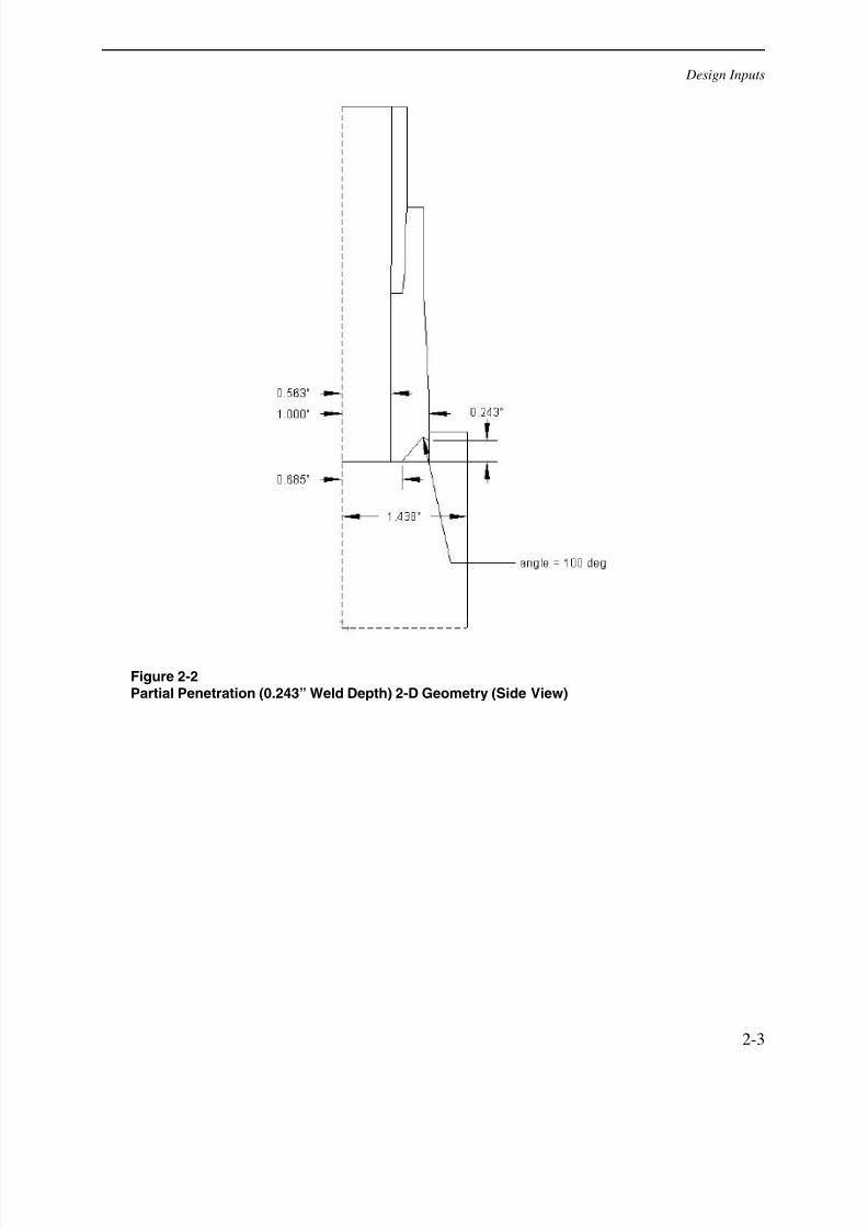
Figure 2-2Partial Penetration (0.243” Weld Depth) 2-D Geometry (Side View)
2-3
7/29/2019 Devt of Tube Repair Techniques for HR Steam Generators
http://slidepdf.com/reader/full/devt-of-tube-repair-techniques-for-hr-steam-generators 22/140
Design Inputs
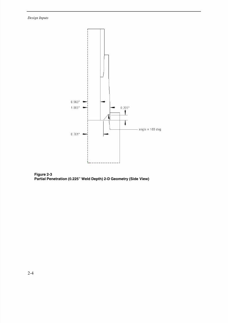
Figure 2-3Partial Penetration (0.225” Weld Depth) 2-D Geometry (Side View)
2-4
7/29/2019 Devt of Tube Repair Techniques for HR Steam Generators
http://slidepdf.com/reader/full/devt-of-tube-repair-techniques-for-hr-steam-generators 23/140
Design Inputs
Material Properties
The material specified by EPRI for all three configurations is P91 (9Cr-Mo). The temperaturewas given as 1000ºF for the evaluated header. The material properties for P91 at 1000ºF are
shown in Table 2-1.
Table 2-1Material Properties for P91 Material at 1000ºF
Property Value Unit
Elastic Modulus 25.4E+06 Psi
Secant Coefficient ofThermal Expansion
6.90E-06 in/in/ oF
Poisson's Ratio 0.3
Density 0.277 lb/in3
Loads
Internal Pressure Boundary Conditions
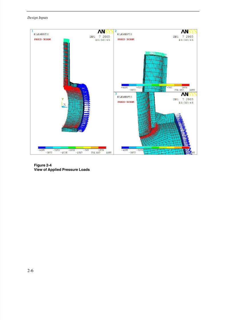
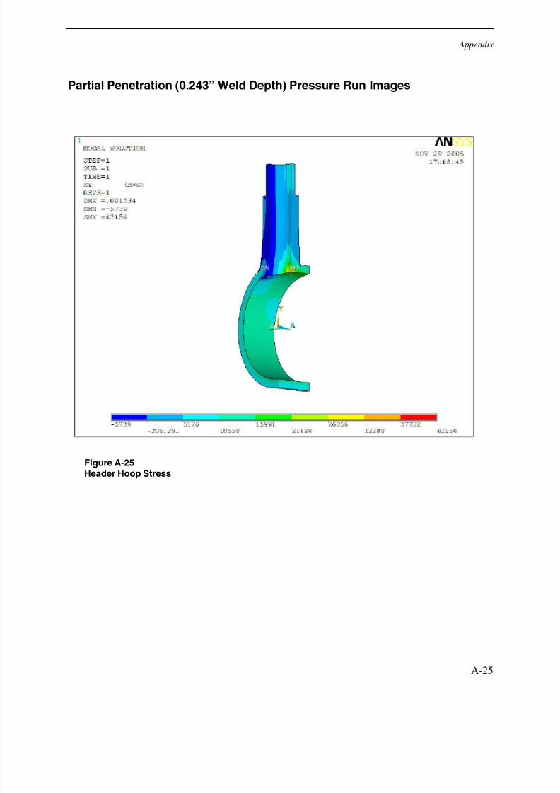
The pressure stress run was made using an internal pressure of 1800 psi. This pressure wasapplied to the inner diameter of the tube and header. It should be noted that this pressure wasalso applied to all faces of the lack of weld fusion gap in the original configuration. Along withthe internal pressure, an equivalent blow-off pressure was applied to the end of the tube andheader cross-section opposite of the tube. Figure 2-4 shows the applied pressures for the originalconfiguration.
Bending Moment Boundary Conditions
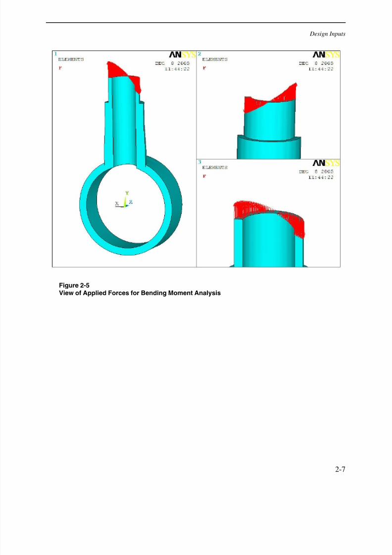
To simulate the effects of a bending moment, a force in the y-direction (tube axial direction) wasplaced on each node of the tube end face. The total sum of the absolute value of the nodal forceswas 1000 in-lbs. It should be noted that one half of the modeled tube face was assigned positiveforces and the other half was assigned equal but opposite forces to create a bending moment.
Because no actual value was calculated for the magnitude of this moment, a unit value wasassumed. This allows for easy comparison between the four configurations. Figure 2-5 shows theapplied boundary condition for the bending moment run.
2-5
7/29/2019 Devt of Tube Repair Techniques for HR Steam Generators
http://slidepdf.com/reader/full/devt-of-tube-repair-techniques-for-hr-steam-generators 24/140
Design Inputs
Figure 2-4
View of Applied Pressure Loads
2-6
7/29/2019 Devt of Tube Repair Techniques for HR Steam Generators
http://slidepdf.com/reader/full/devt-of-tube-repair-techniques-for-hr-steam-generators 25/140
Design Inputs
Figure 2-5
View of Applied Forces for Bending Moment Analysis
2-7

7/29/2019 Devt of Tube Repair Techniques for HR Steam Generators
http://slidepdf.com/reader/full/devt-of-tube-repair-techniques-for-hr-steam-generators 26/140
7/29/2019 Devt of Tube Repair Techniques for HR Steam Generators
http://slidepdf.com/reader/full/devt-of-tube-repair-techniques-for-hr-steam-generators 27/140
3 RESULTS
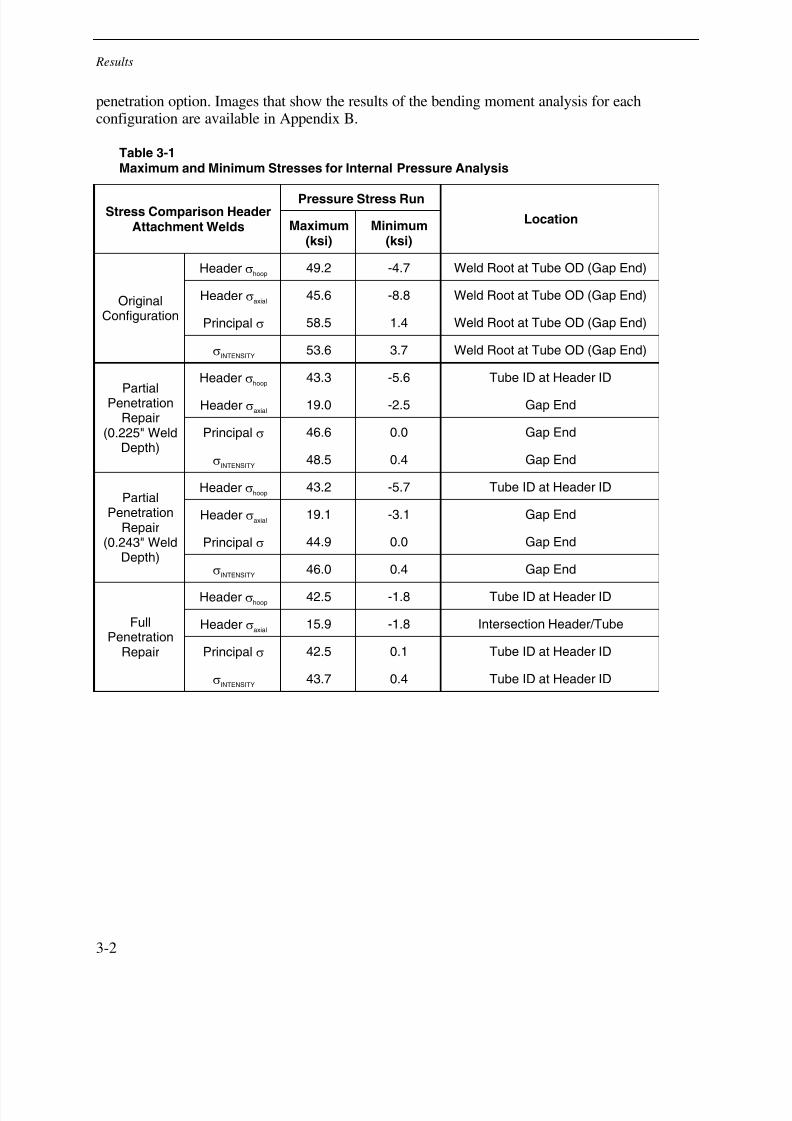
Internal Pressure Application Results
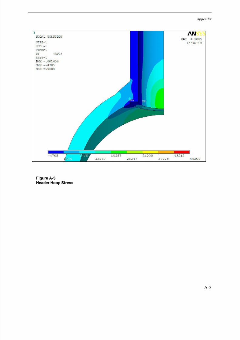
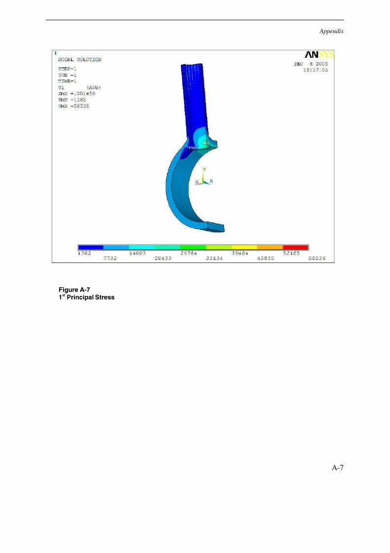
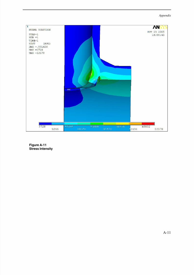
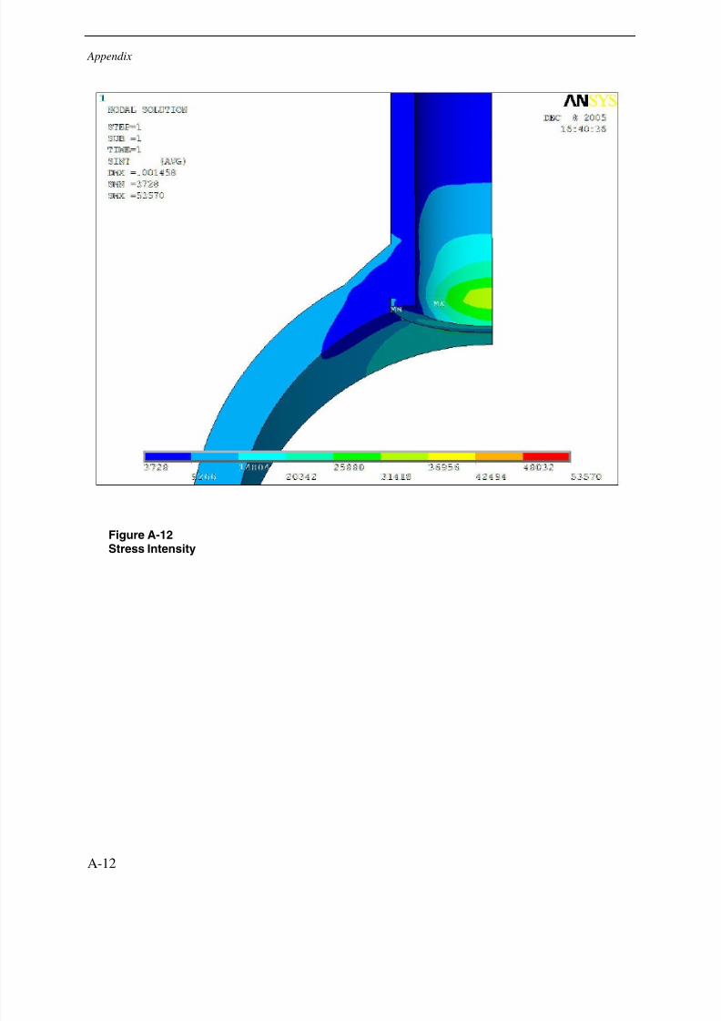
A comparison of maximum and minimum stress values due to internal pressure application foreach configuration can be seen in Table 3-1. Due to the geometry of the original design, it hasthe highest header hoop, header axial, and 1
stprincipal stresses. It also has the highest stress
intensity. All of these maximums for the original configuration are located at the end of the gapbetween the tube and header. Because this gap or lack of fusion is located so that it directly sees
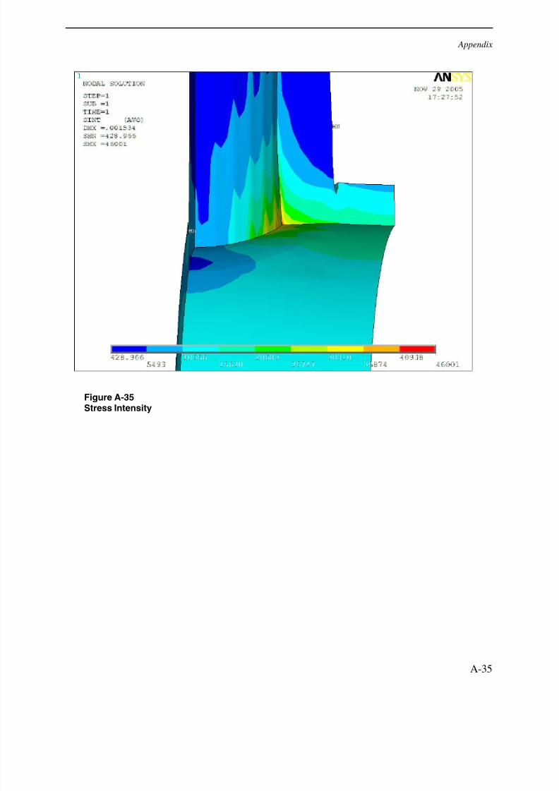
internal pressure (as opposed to the repair welds which have a gap on the outer diameter of theheader), it makes sense that the pressure effects will cause high stress concentrations in thislocation. The actual stress concentration effect may be higher than that indicated in the FE resultsas this is dependent on mesh refinement of the FE model.
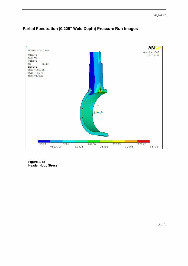
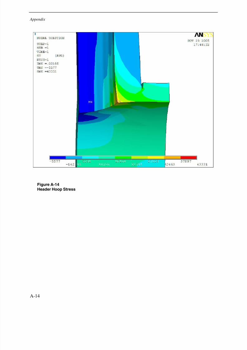
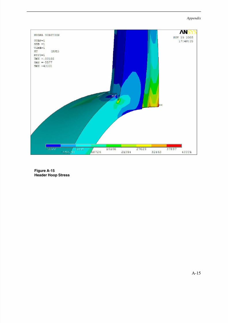
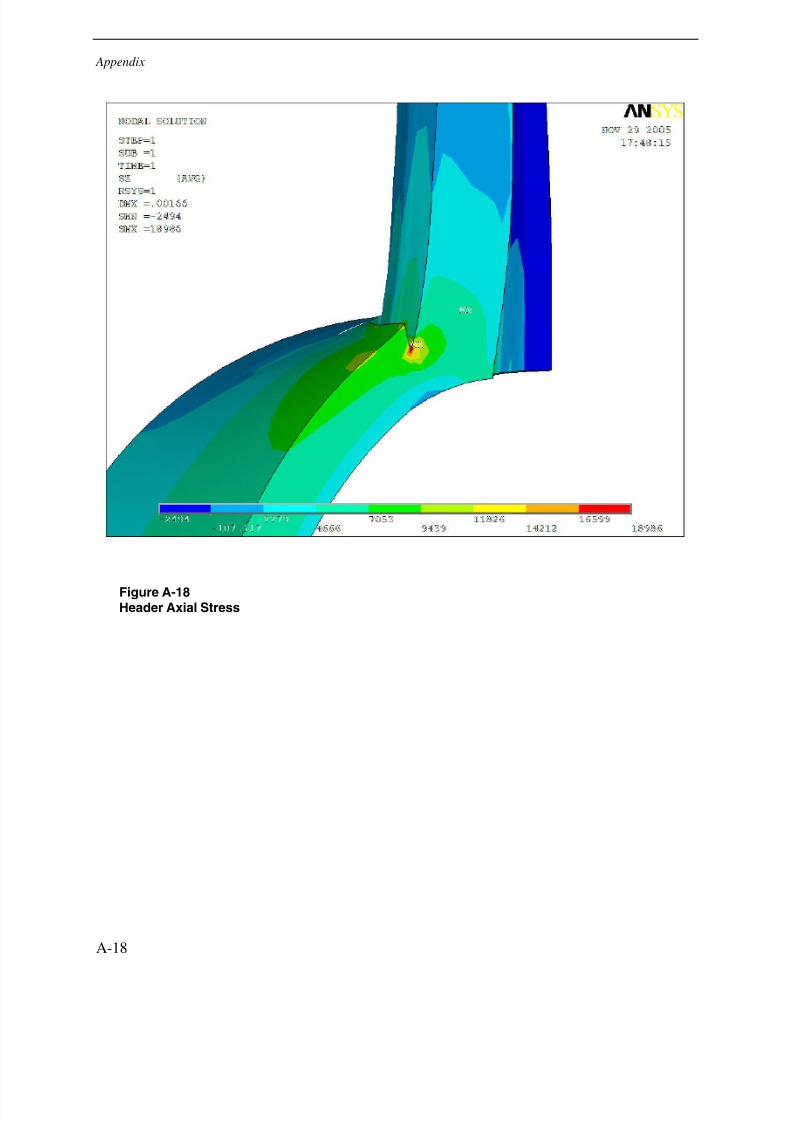
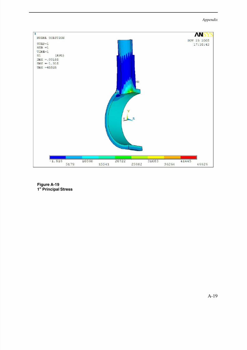
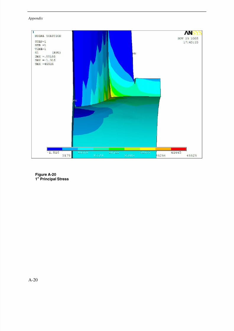
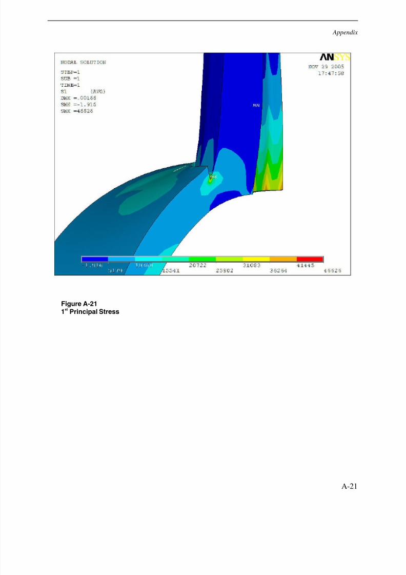
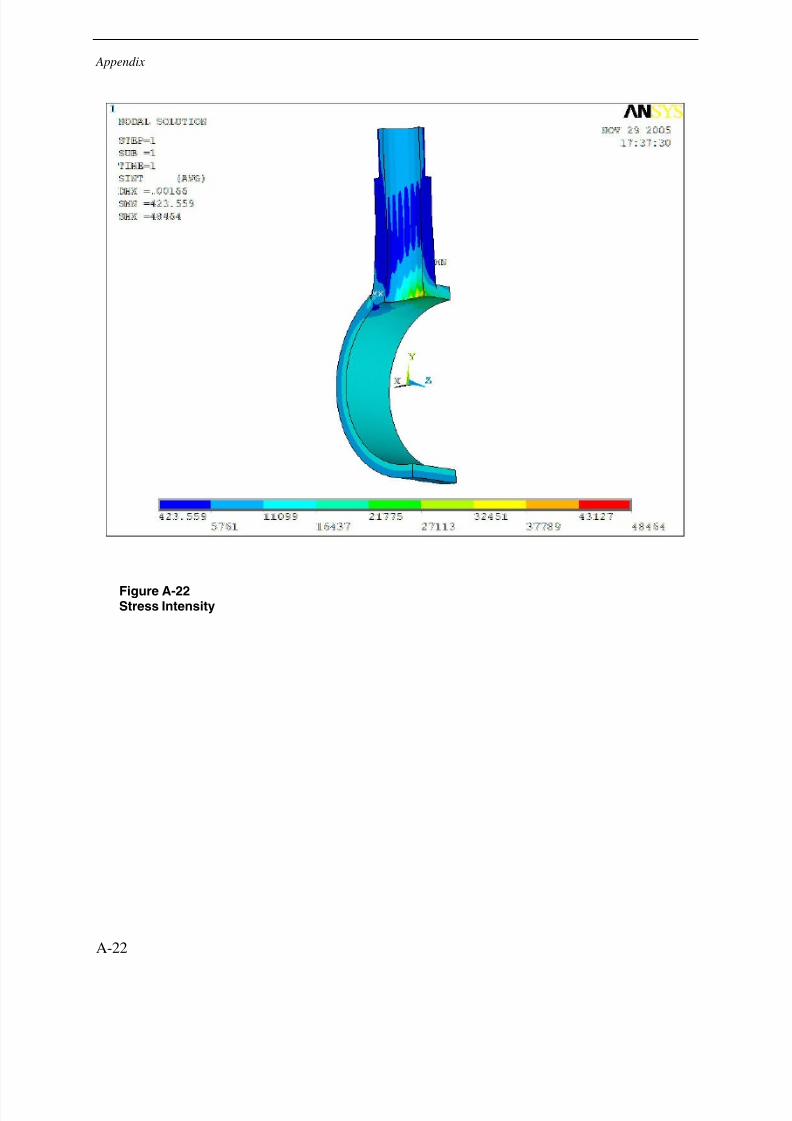
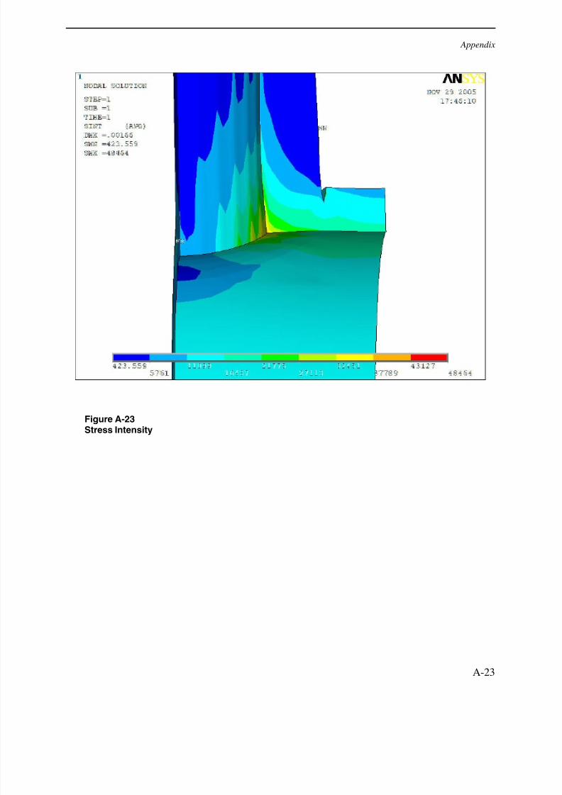
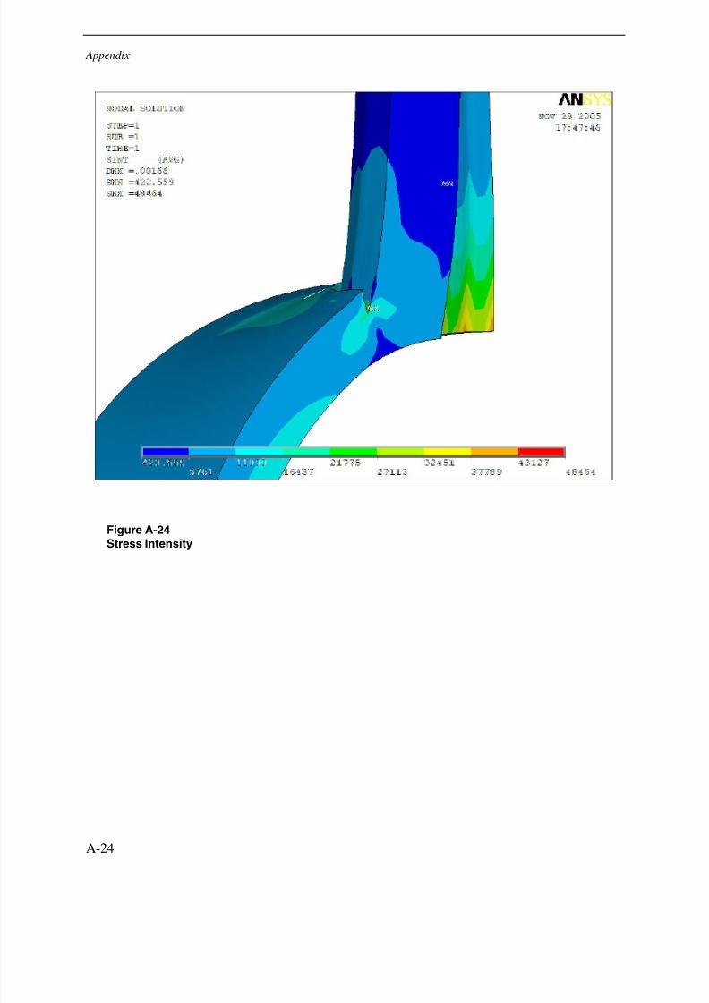
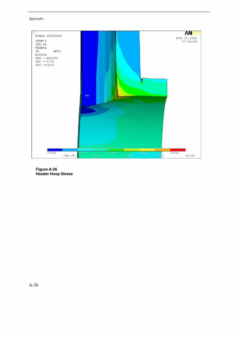
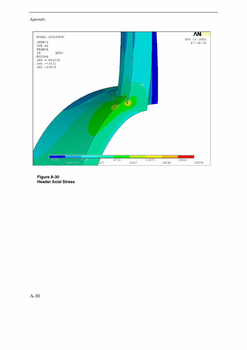
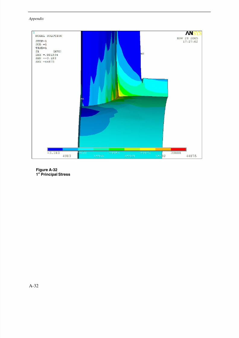
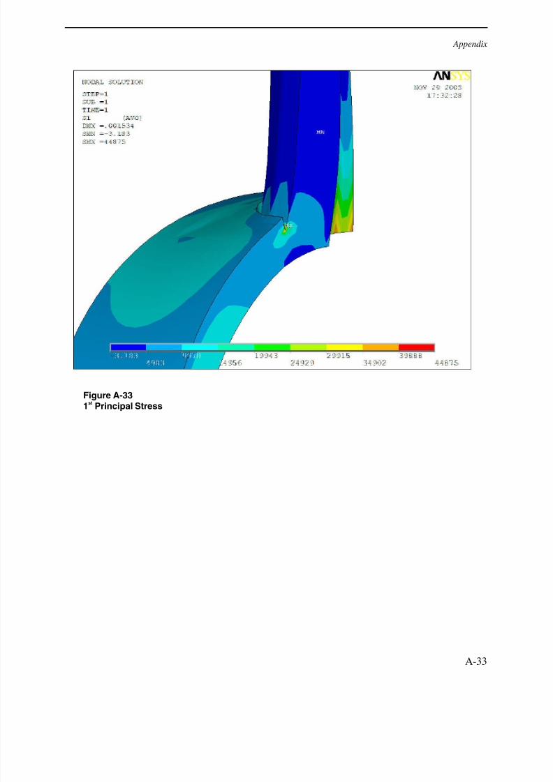
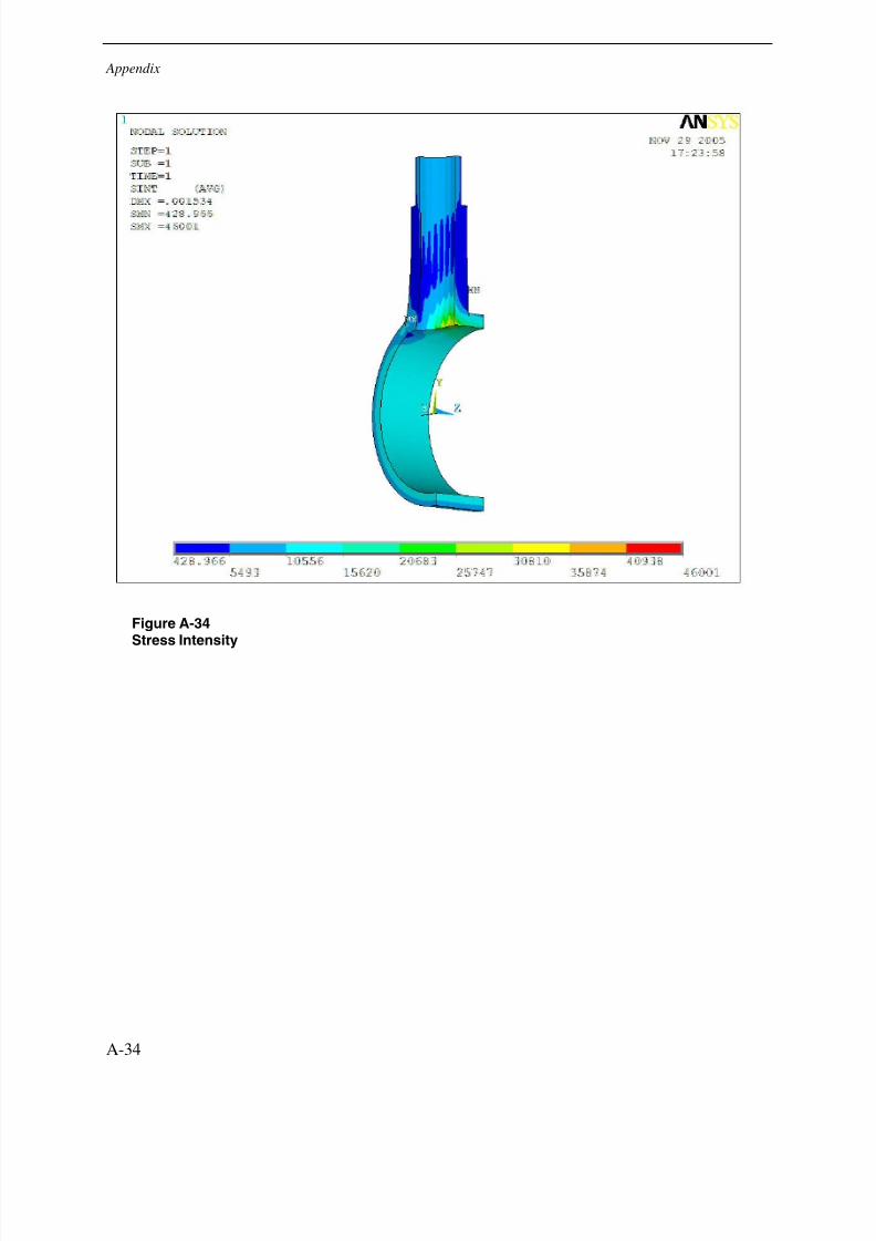
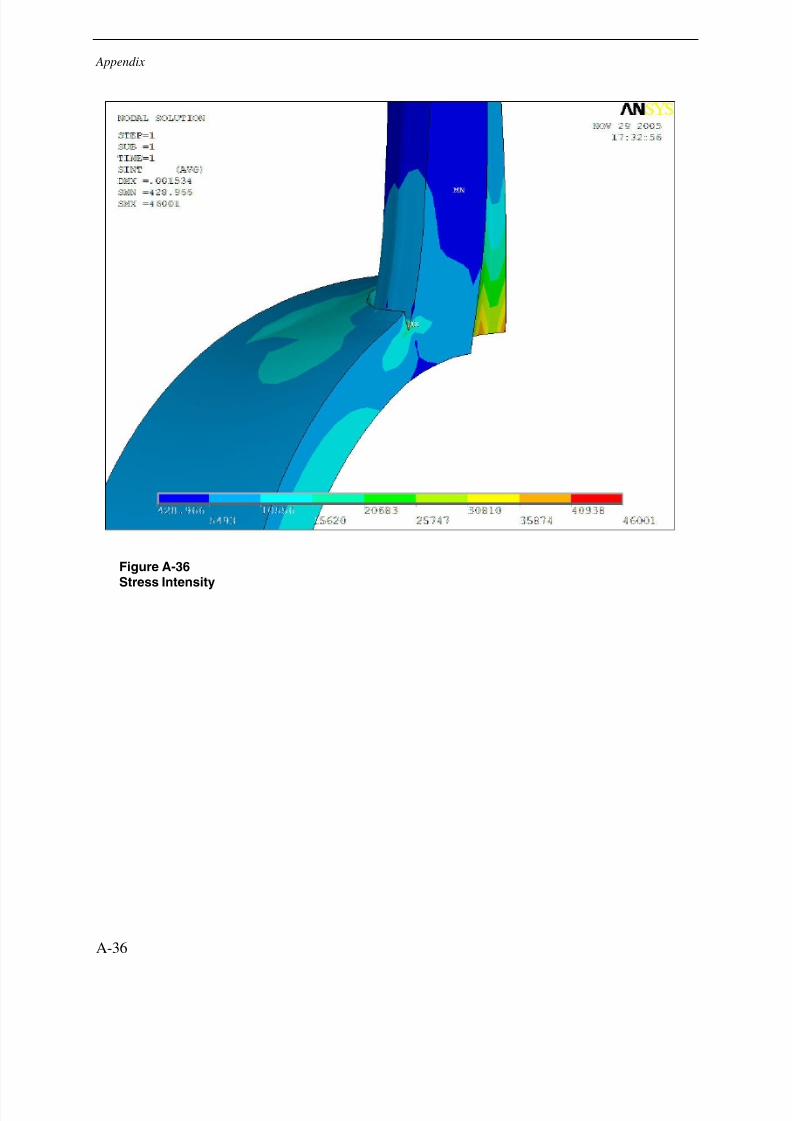
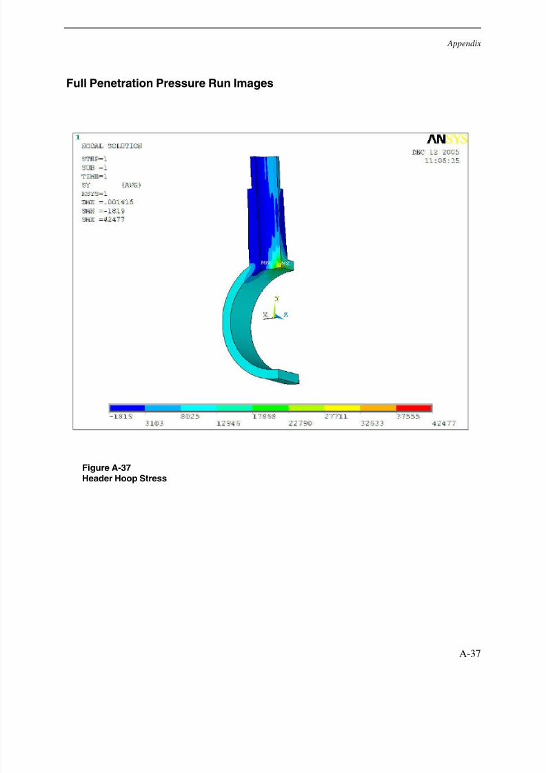
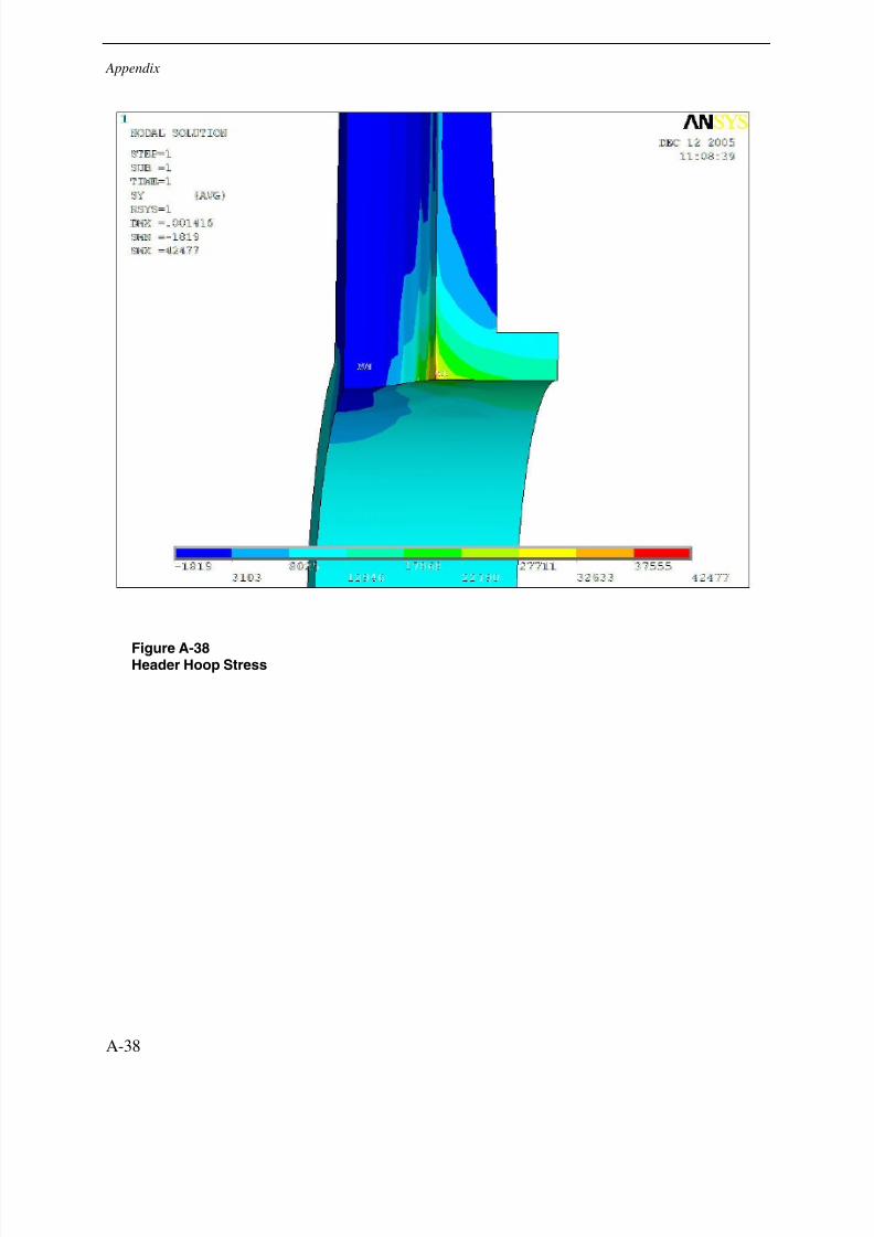
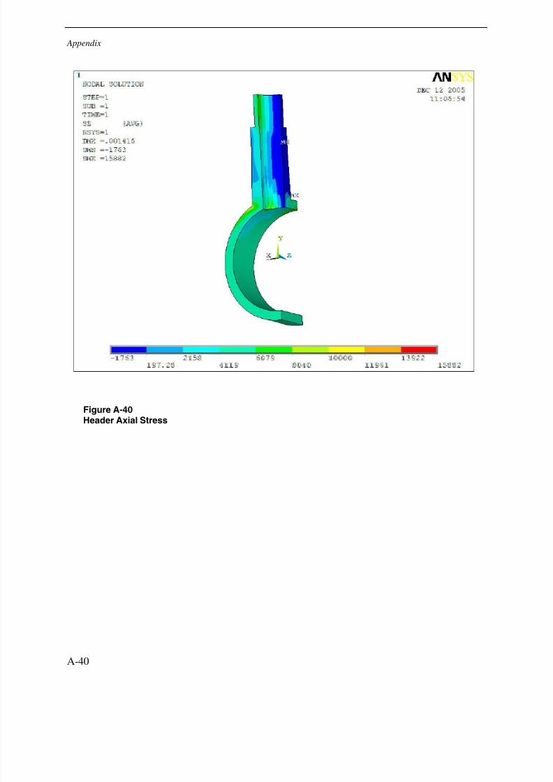
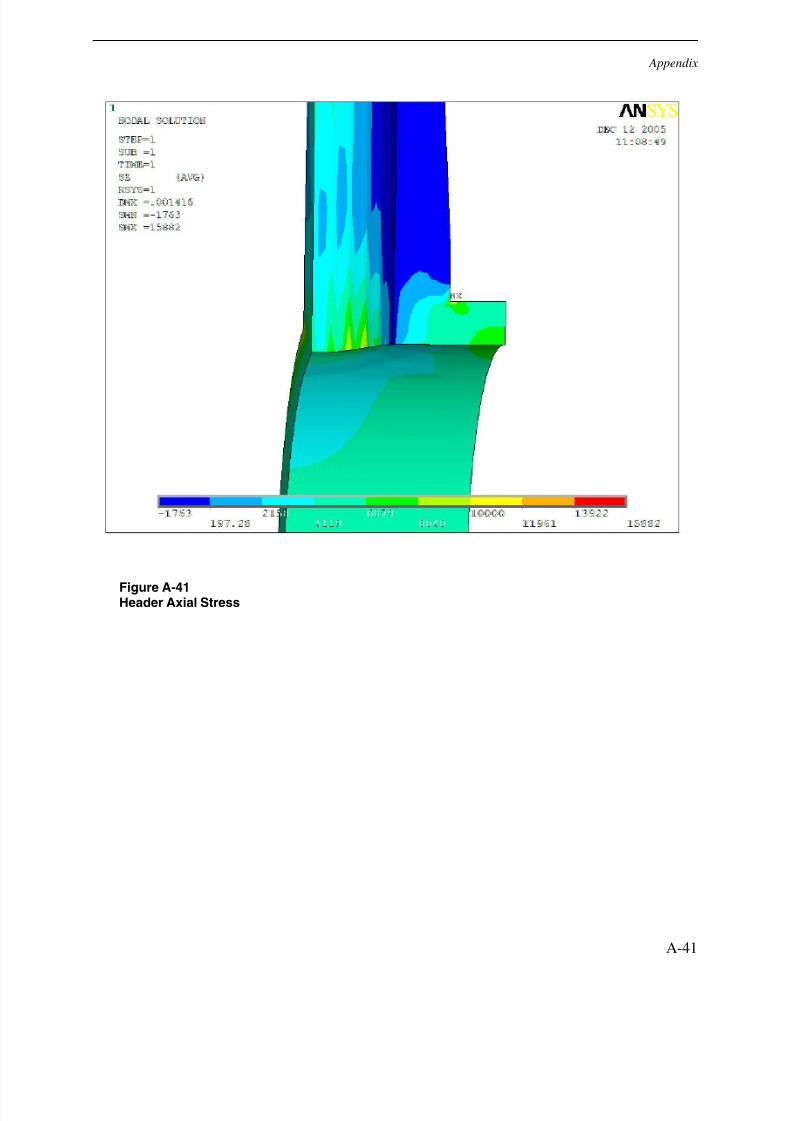
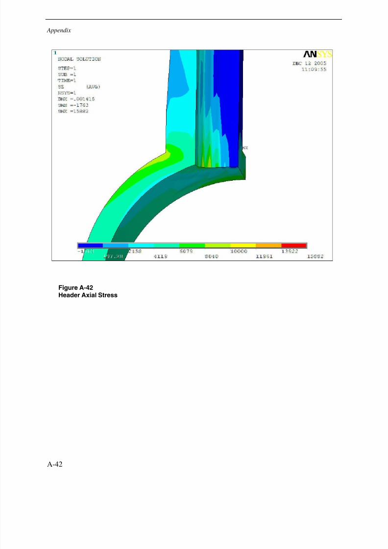
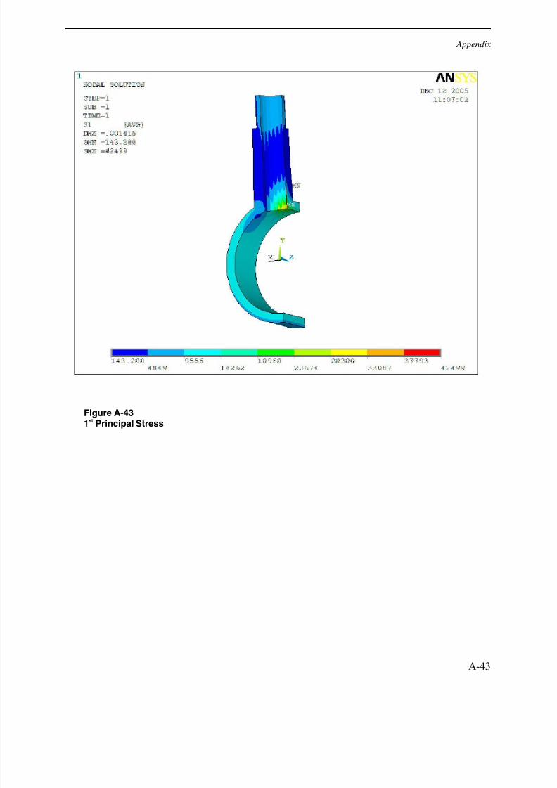
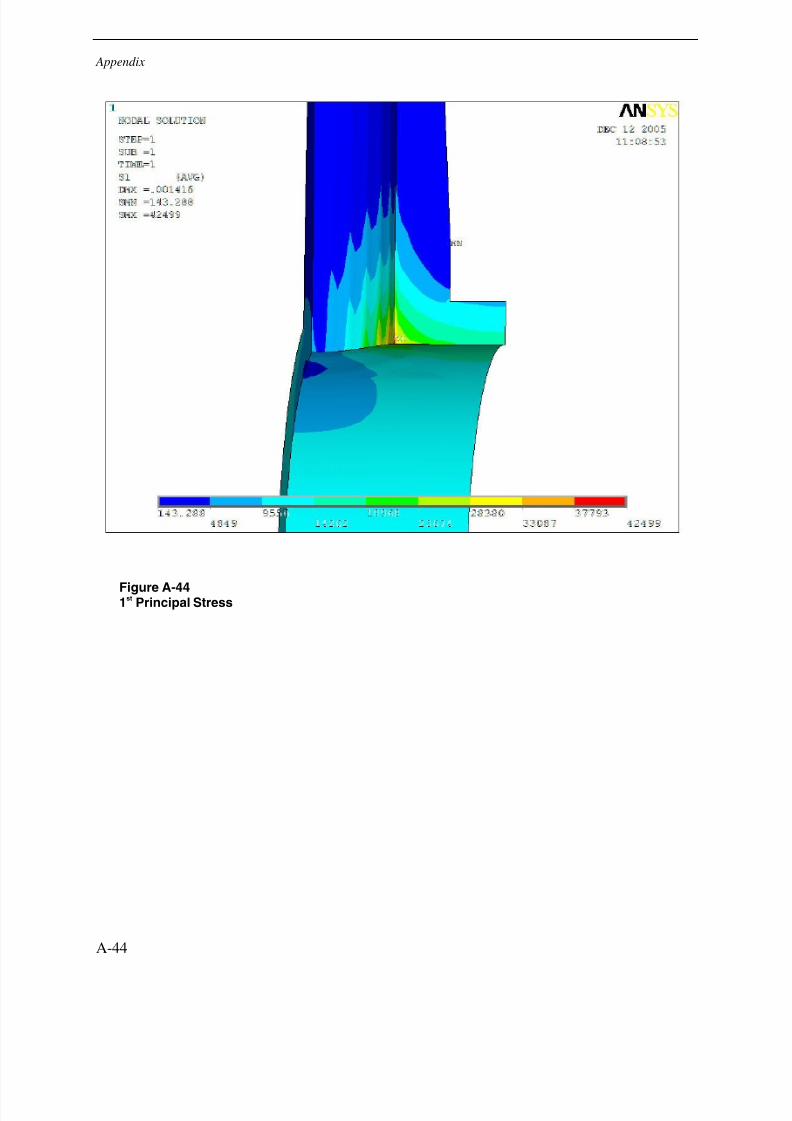
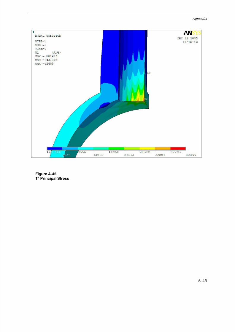
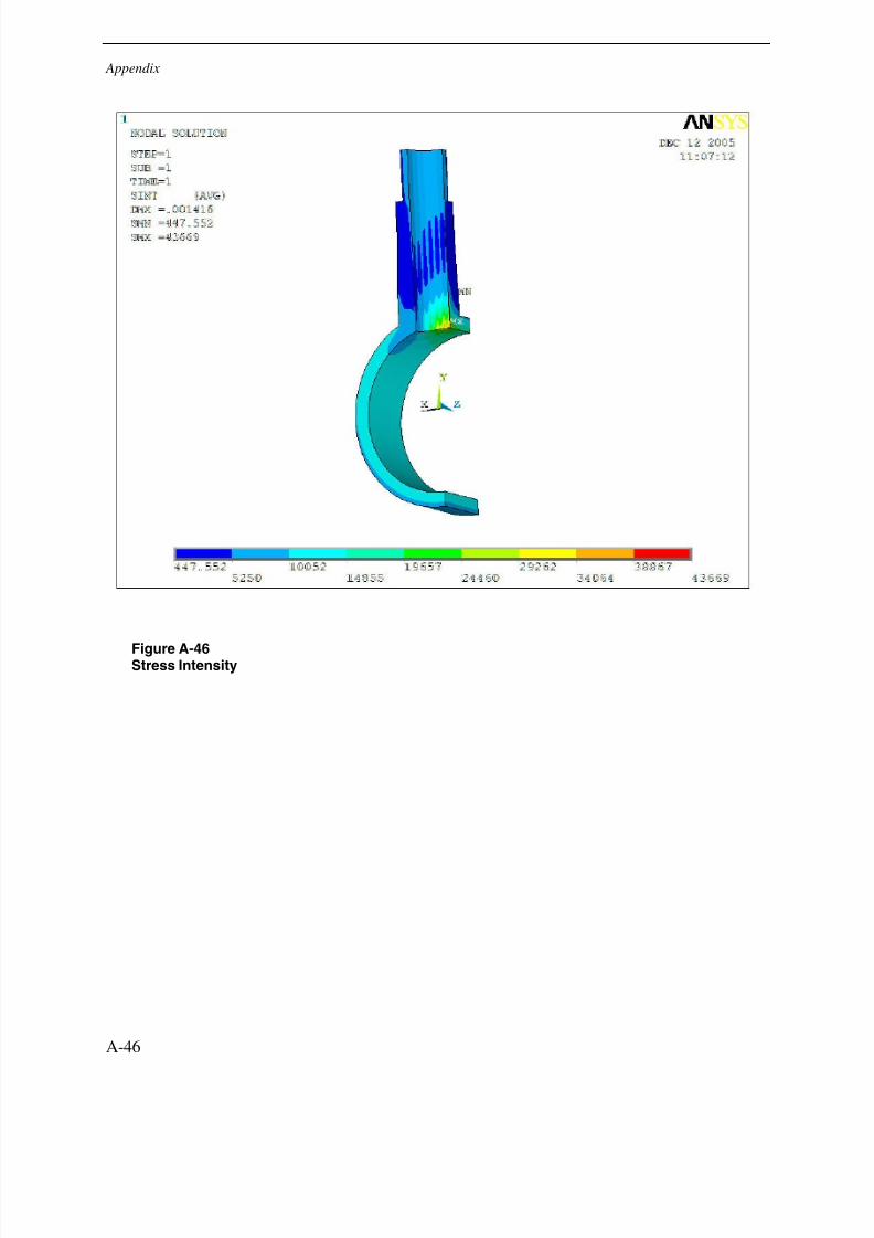
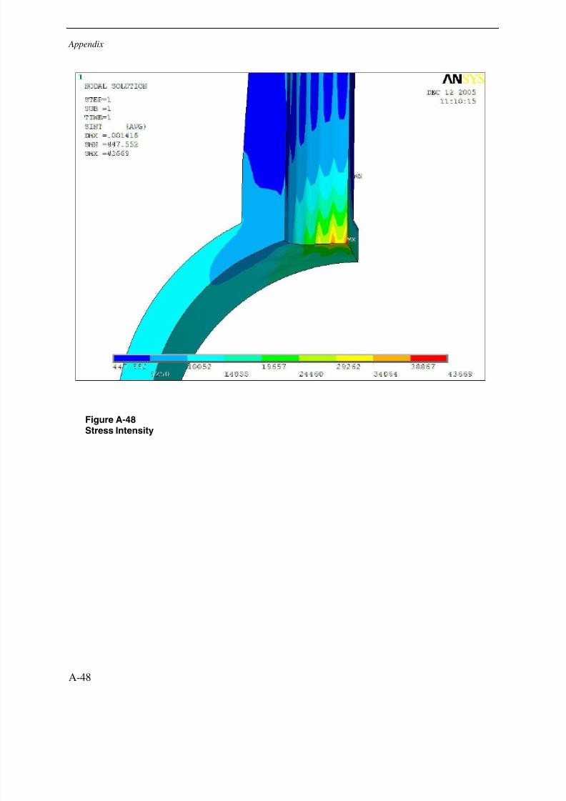
The three repair configurations tested in this analysis show similar results for the pressureapplication. The full penetration repair option does have slightly lower stress values than the twopartial repair configurations. Even though it doesn’t directly see the effects of internal pressure,the lack of fusion created in the two partial penetration configurations does create enough of aconcentration that its stresses are 2 to 17% higher than the full penetration design. Images thatshow the results of the internal pressure analysis for each configuration are available inAppendix A.
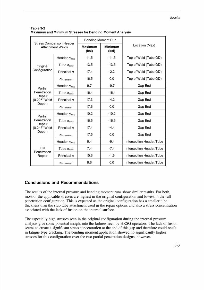
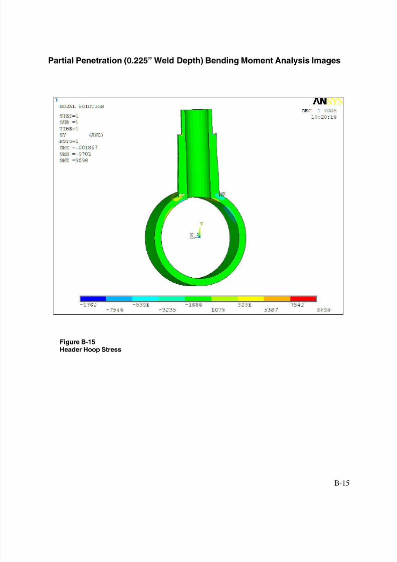
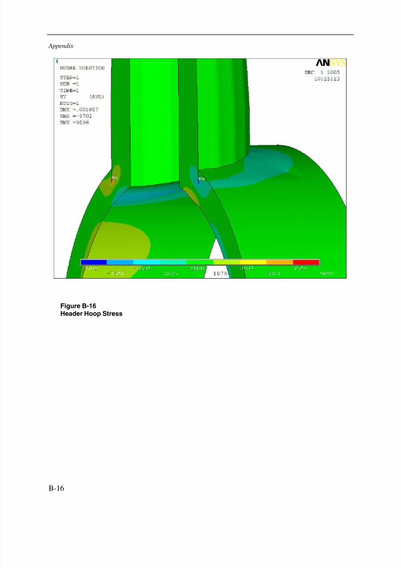
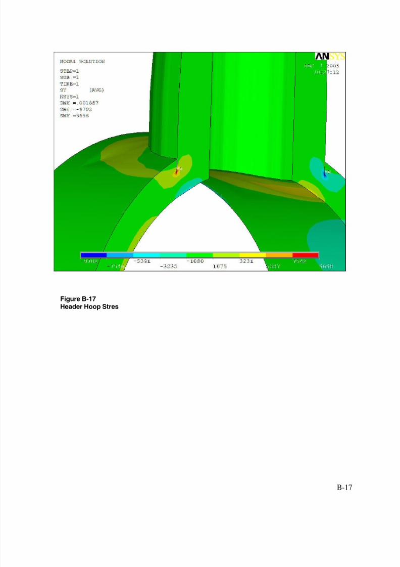
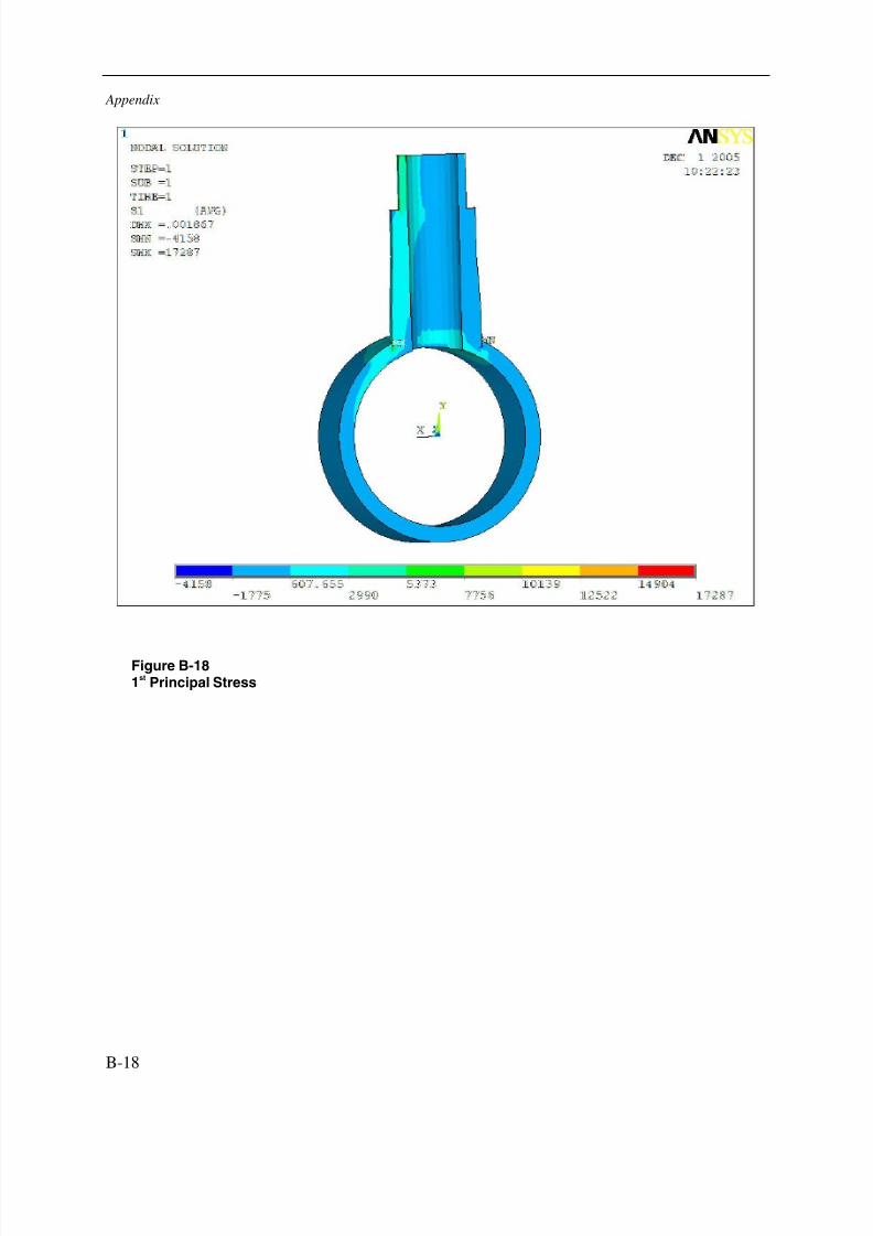
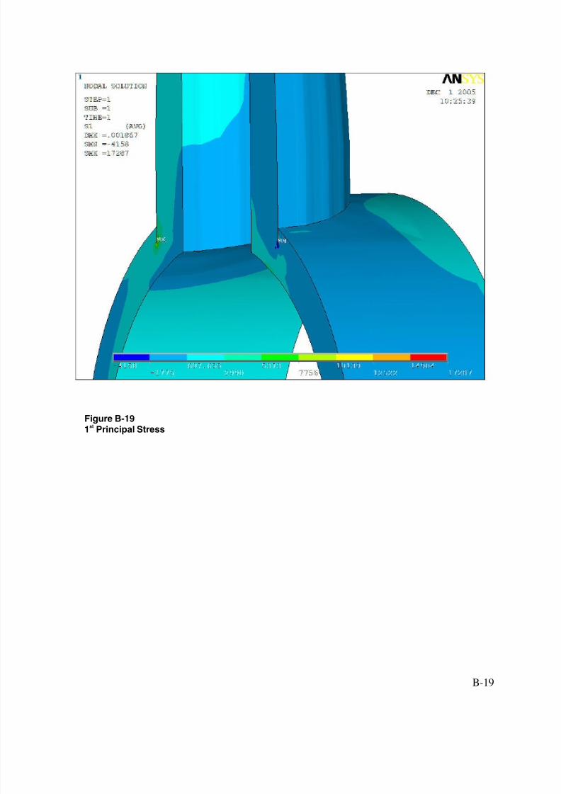
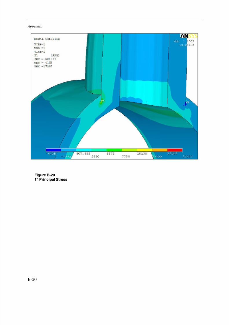
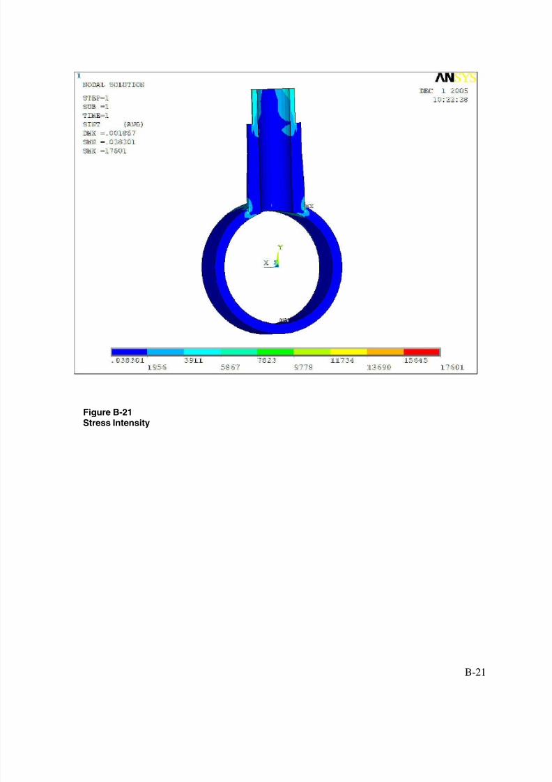
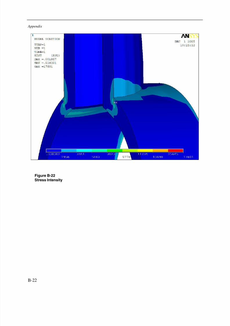
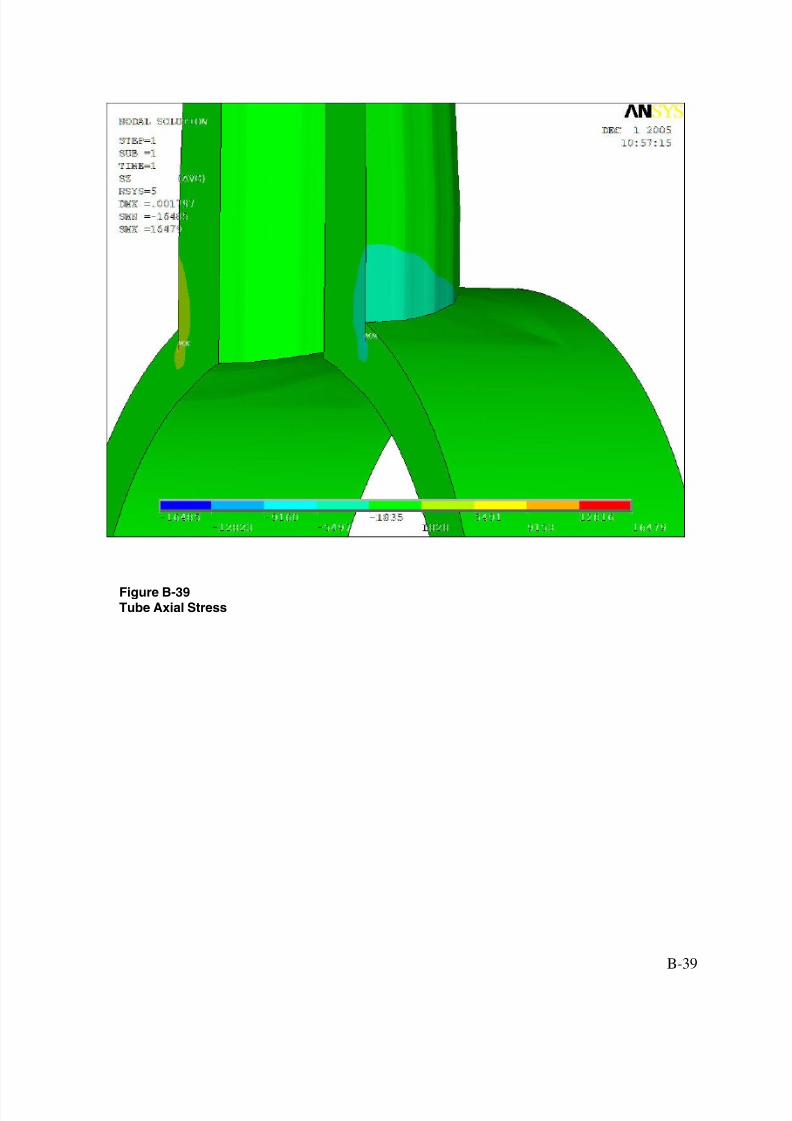
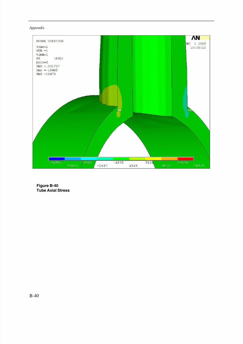
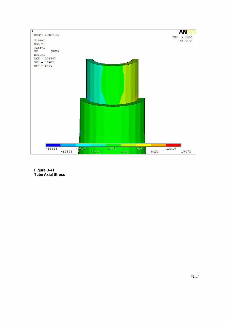
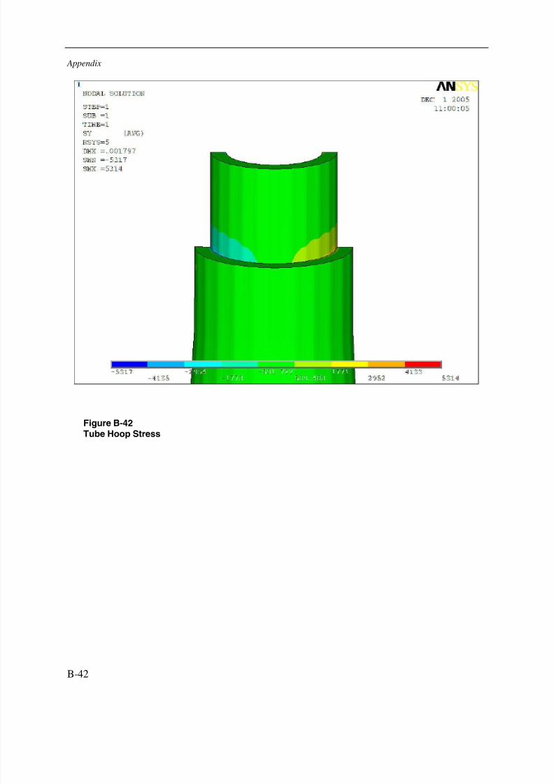
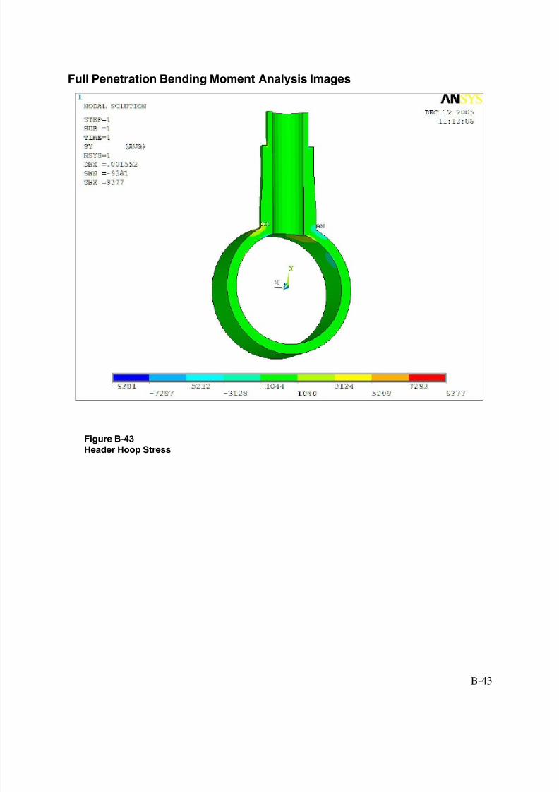
Bending Moment Application Results
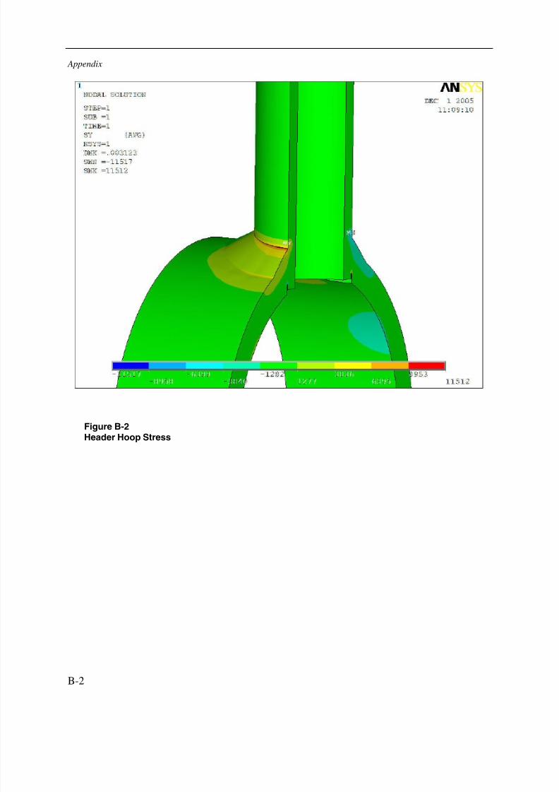
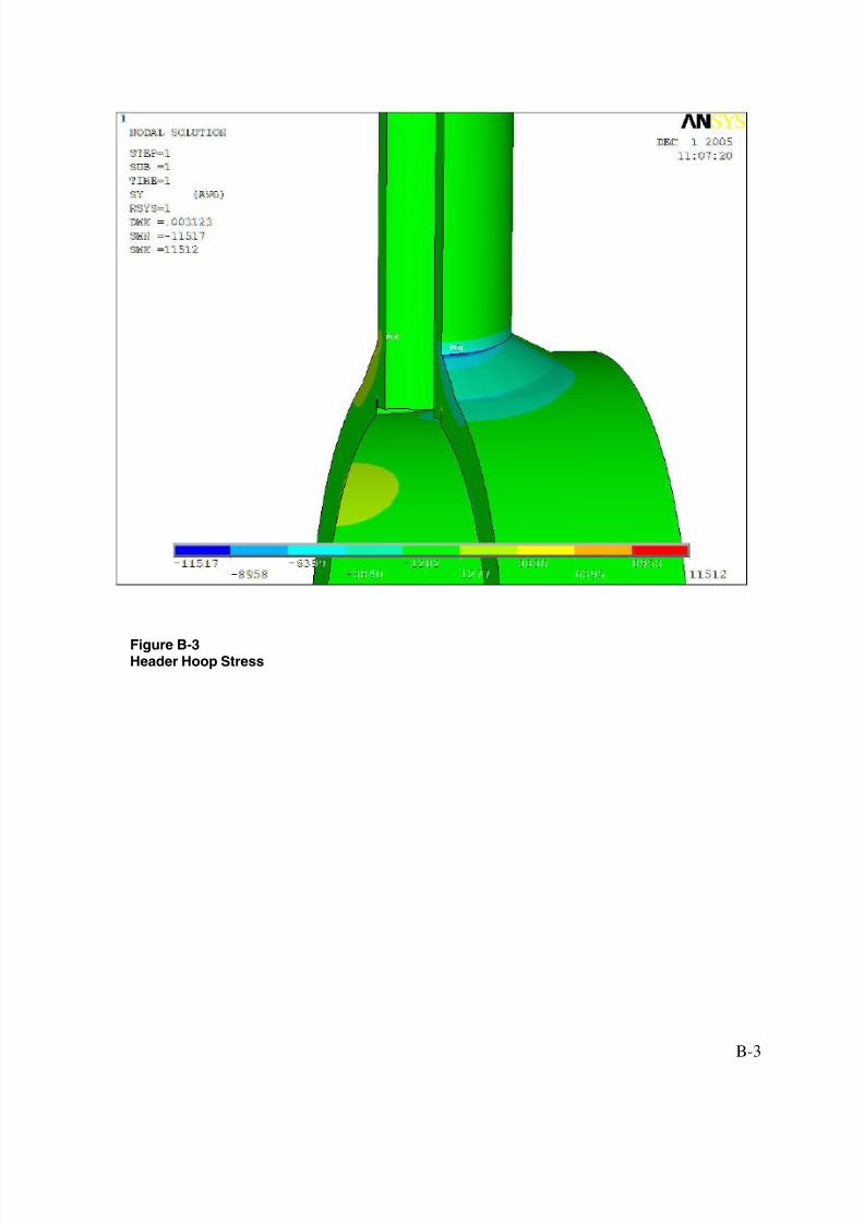
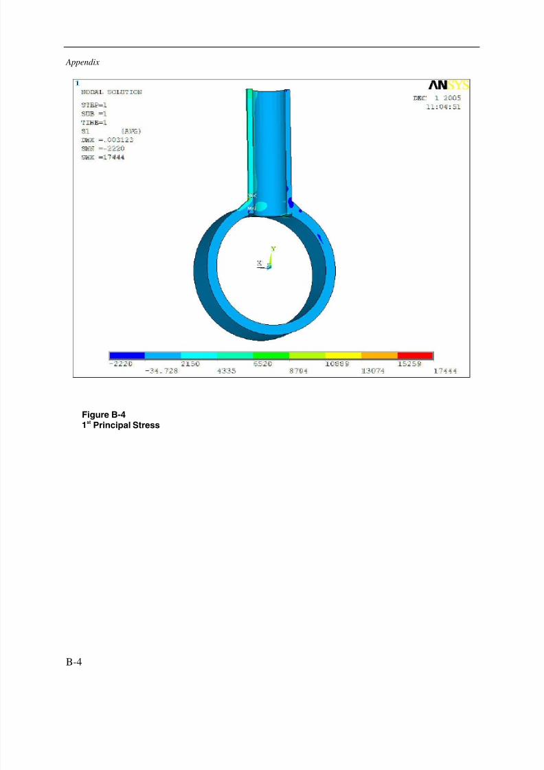
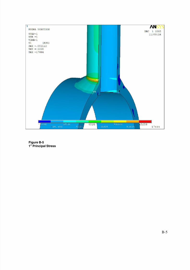
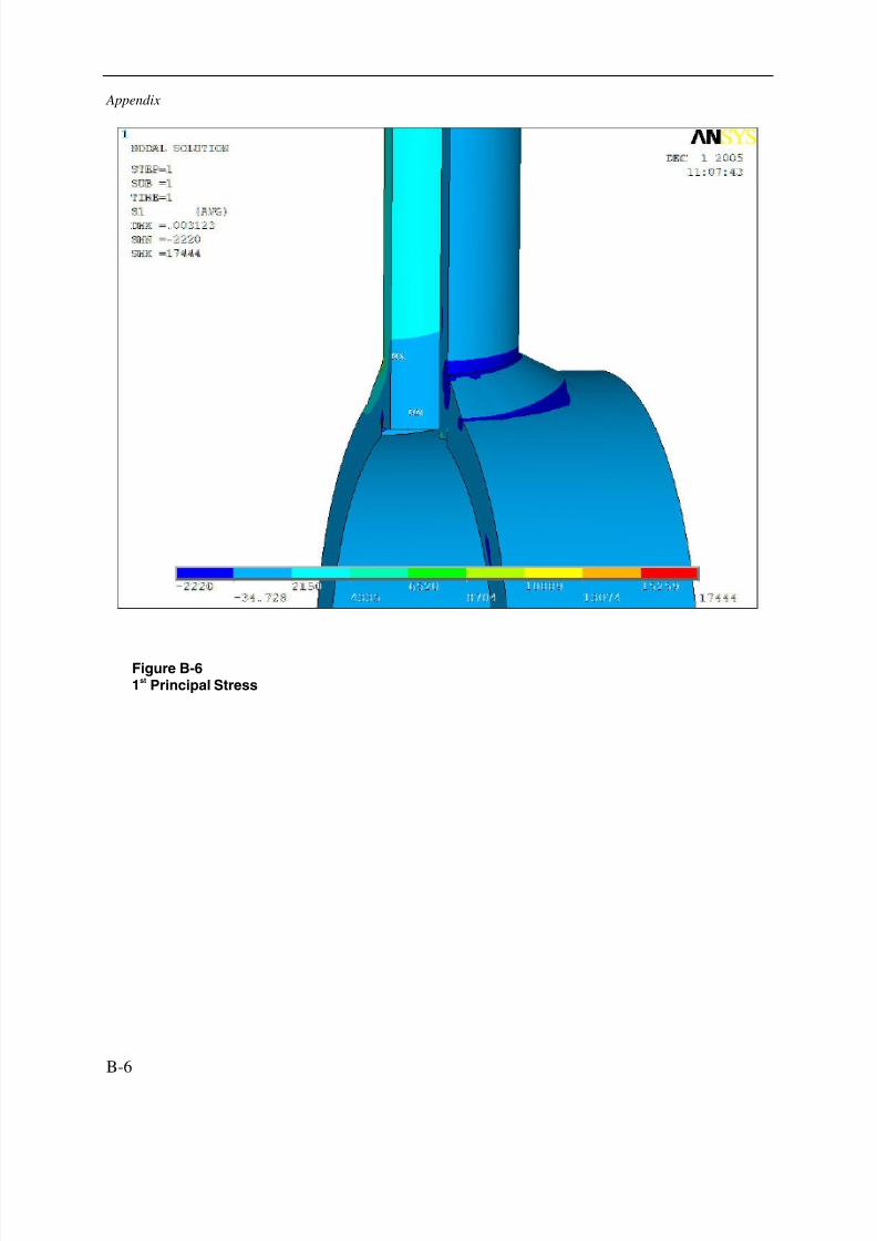
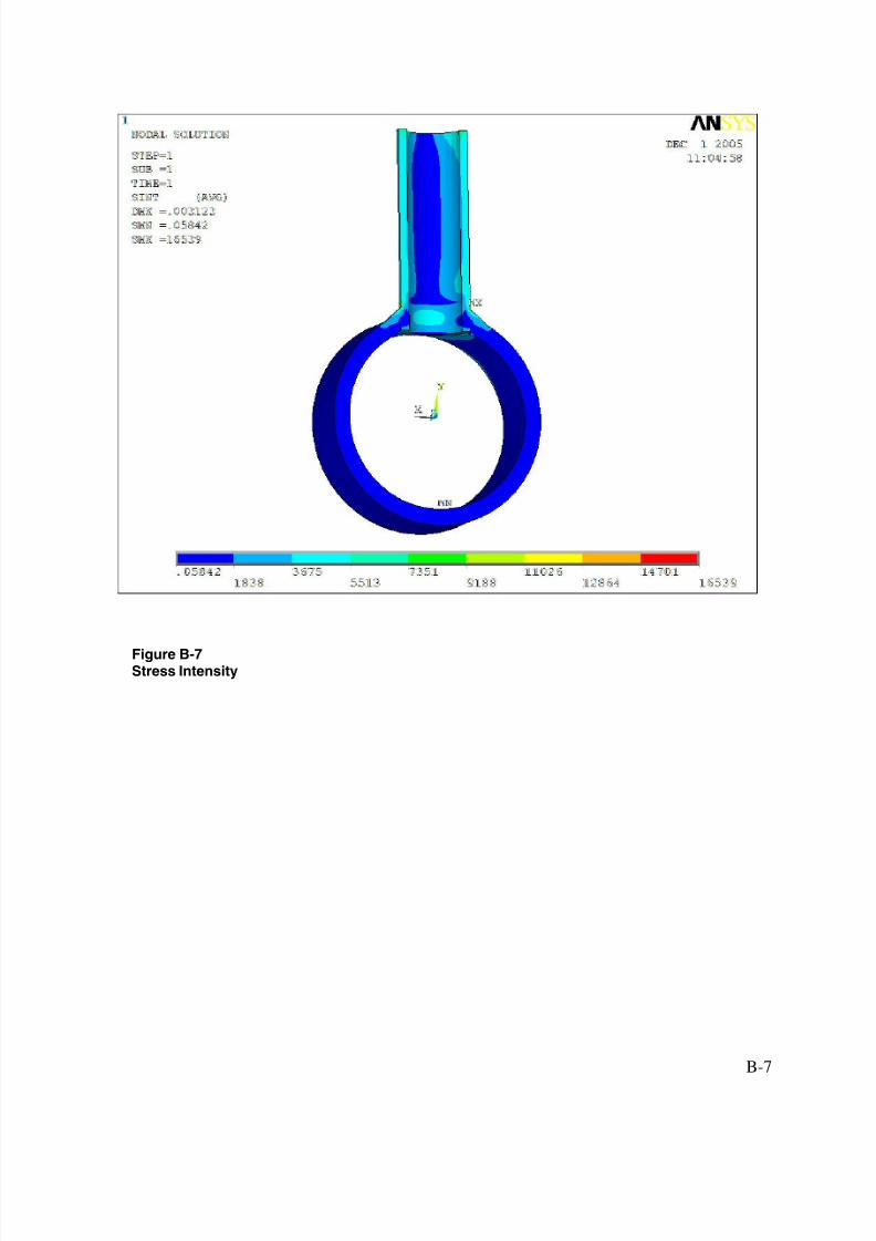
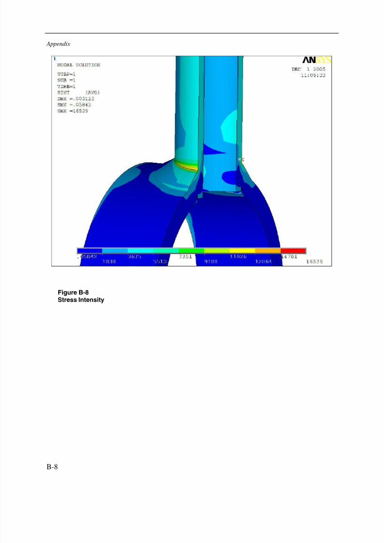
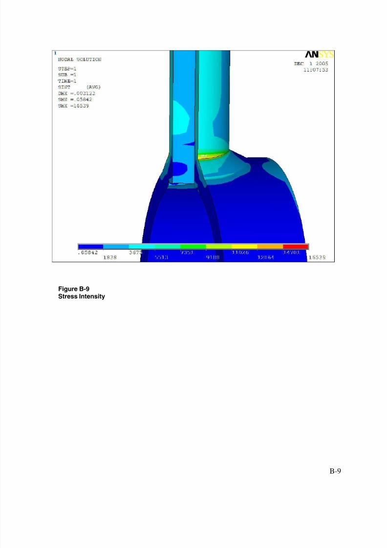
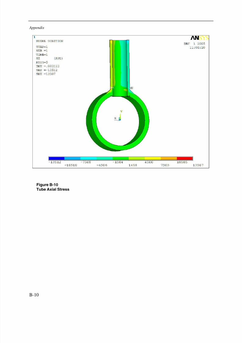
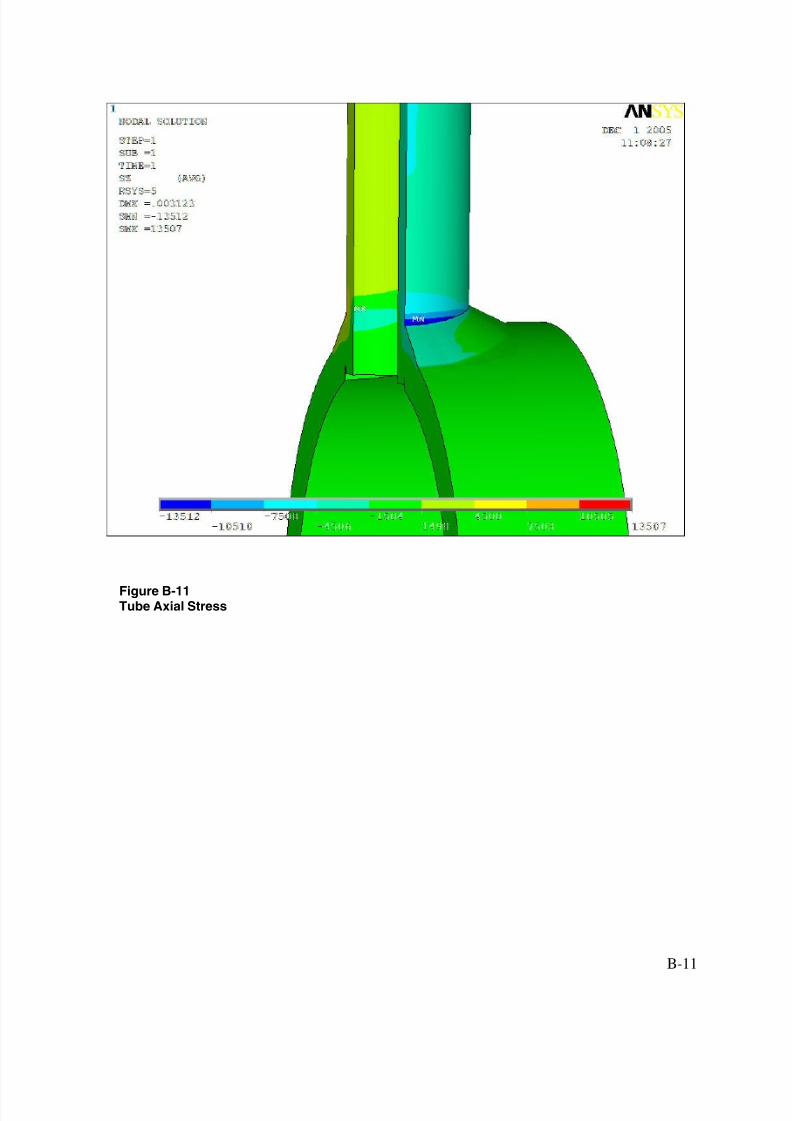
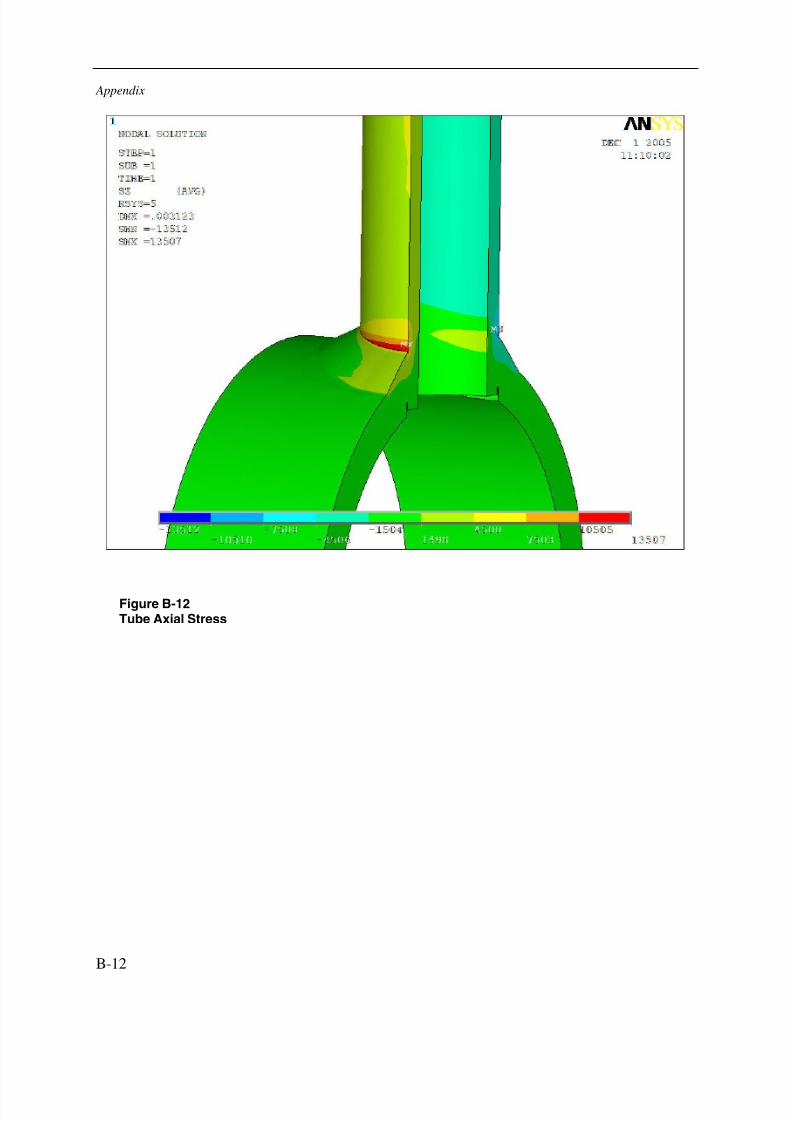
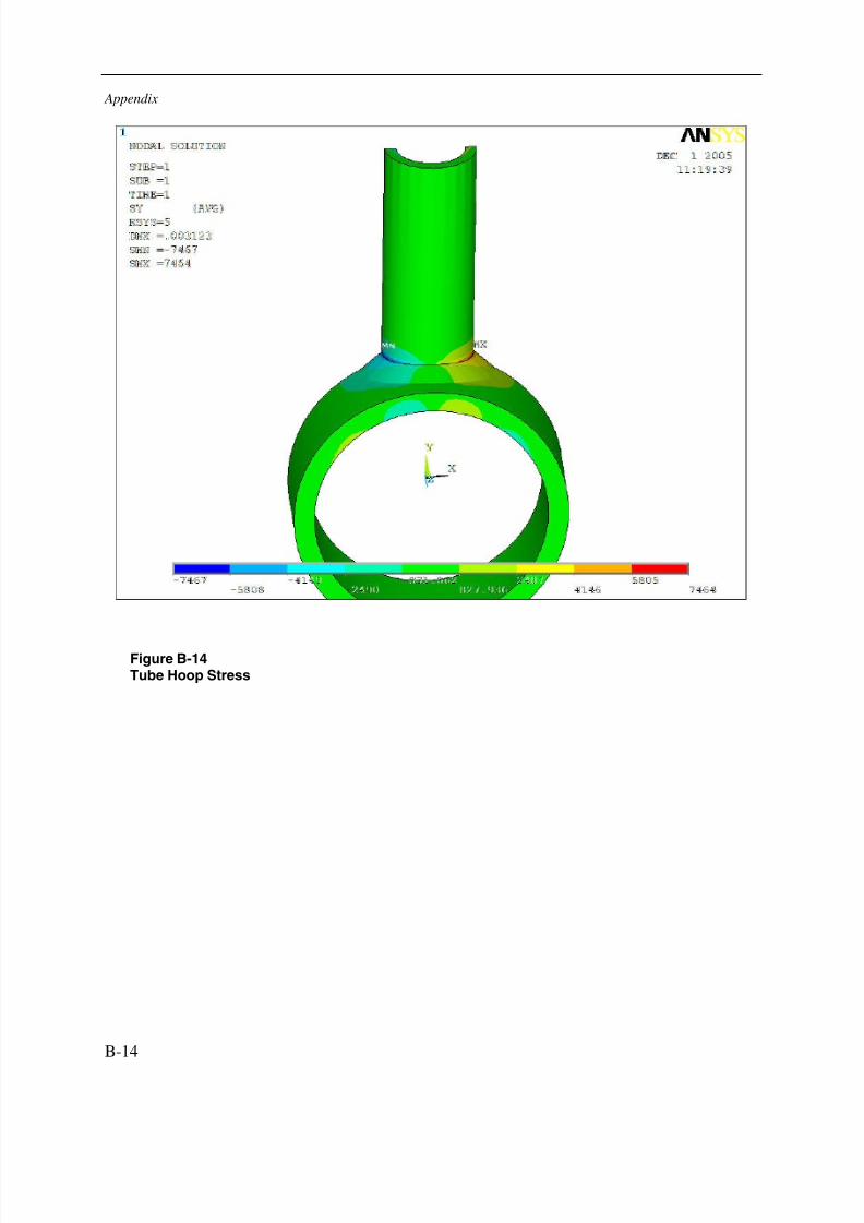
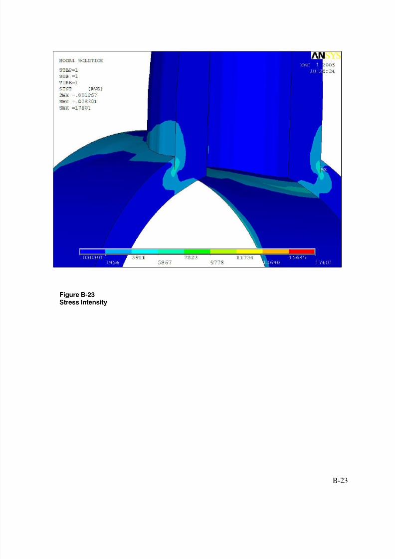
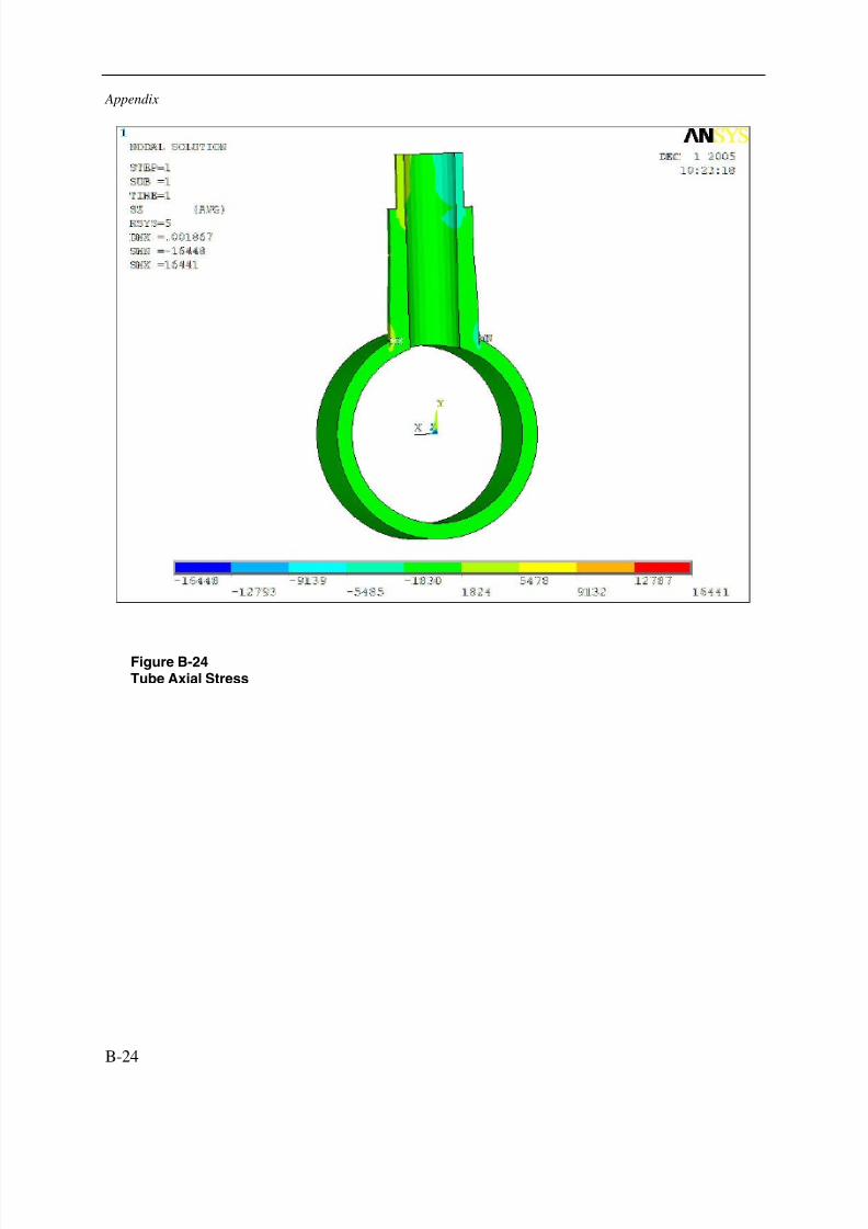
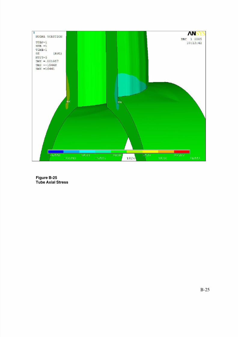
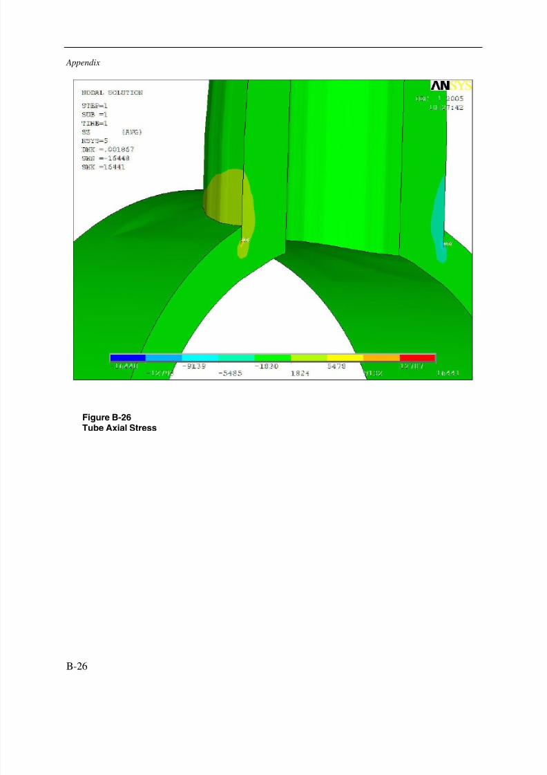
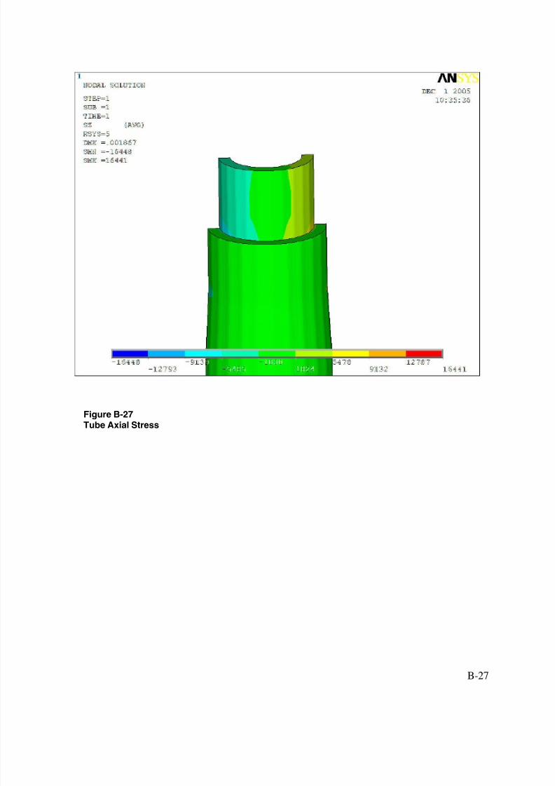
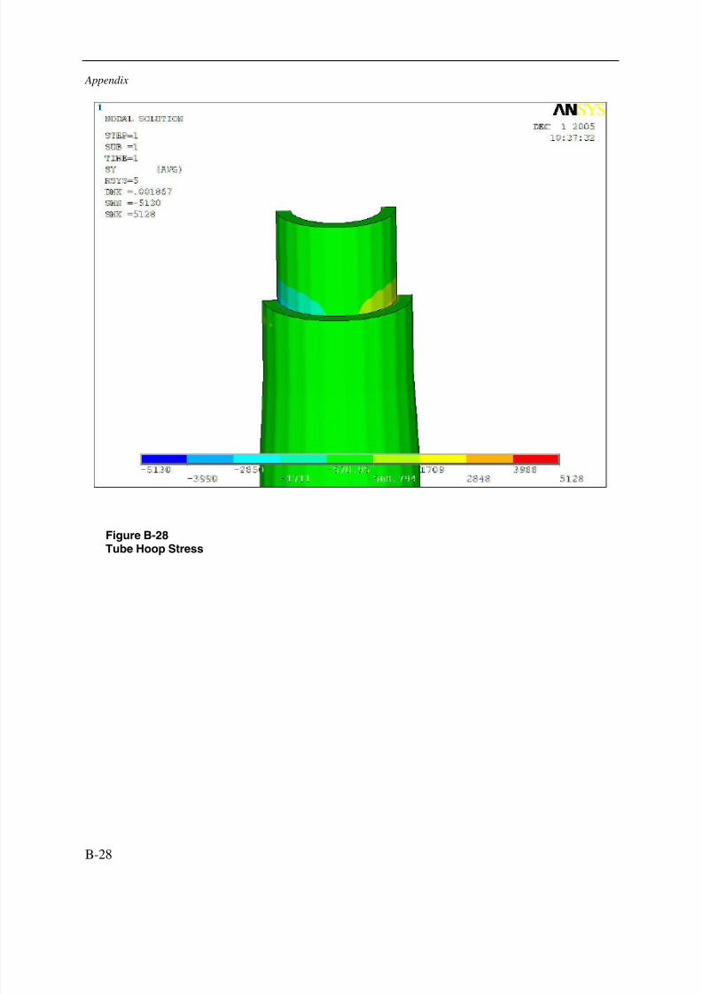
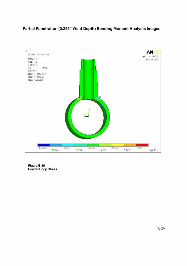
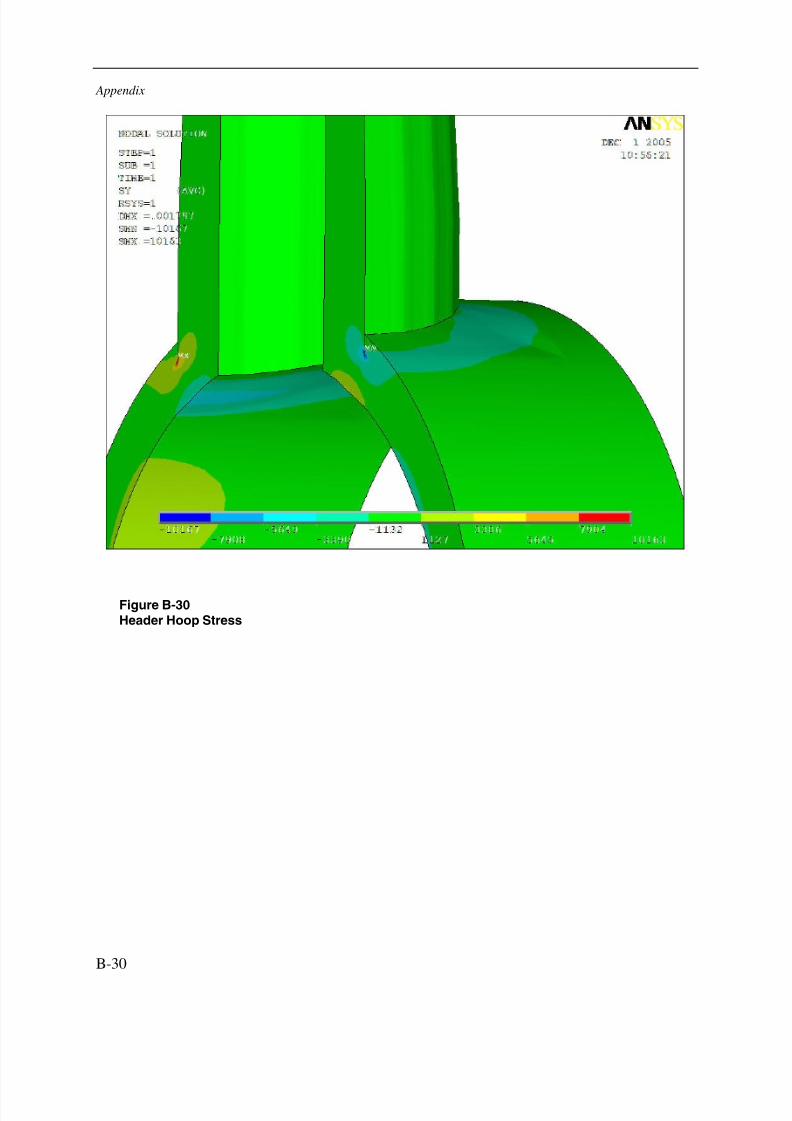
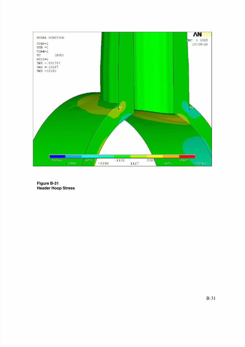
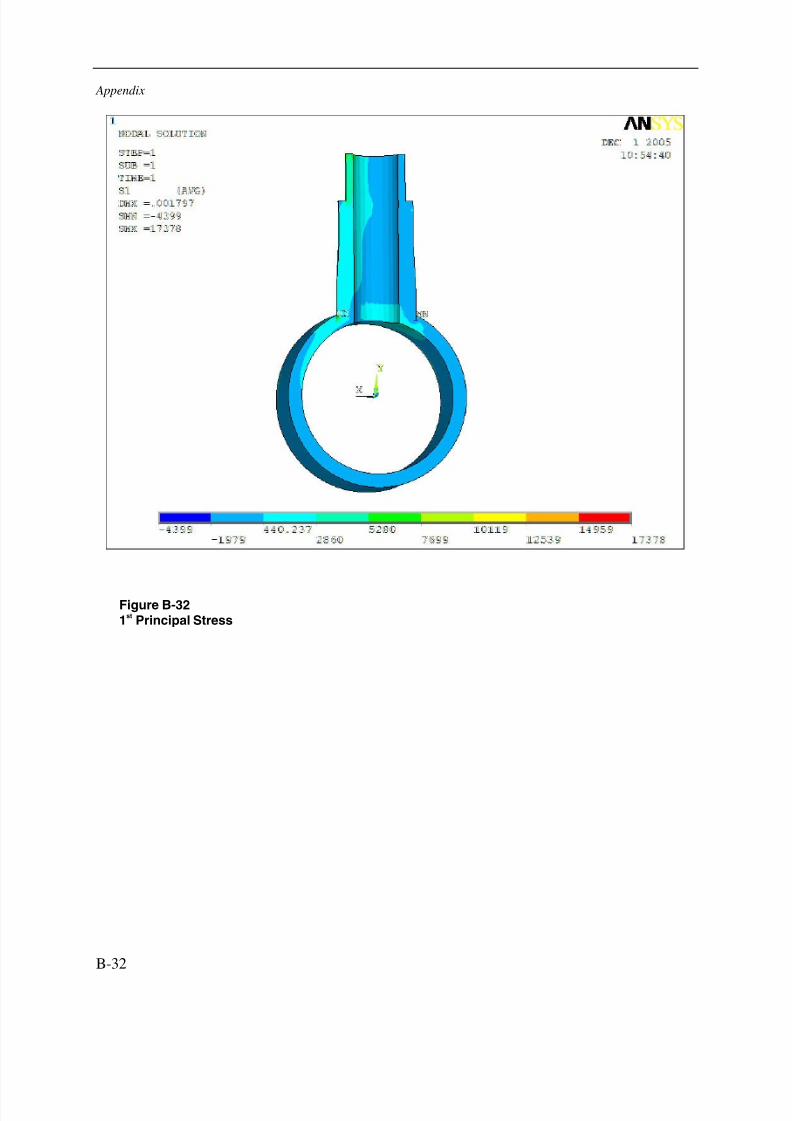
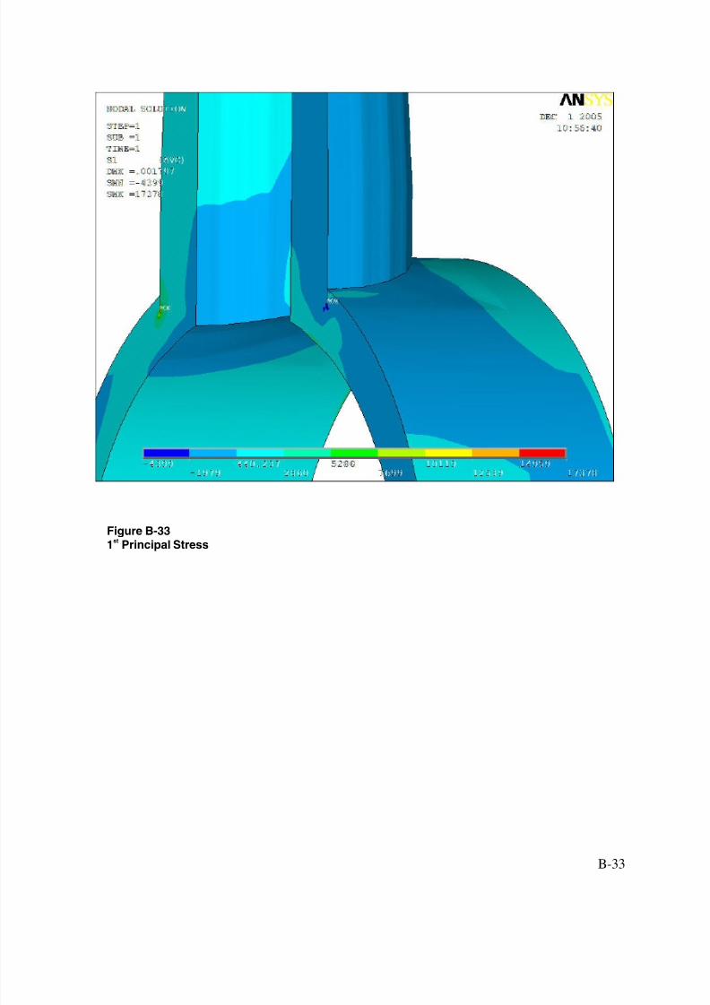
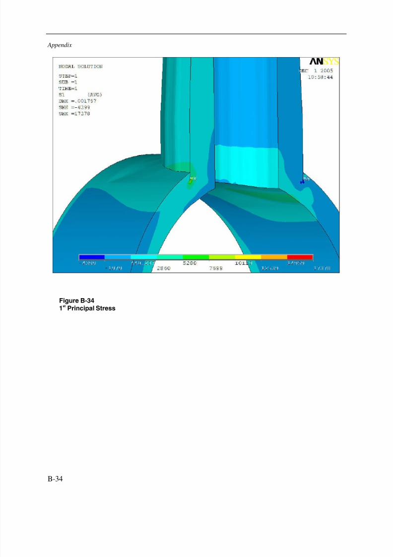
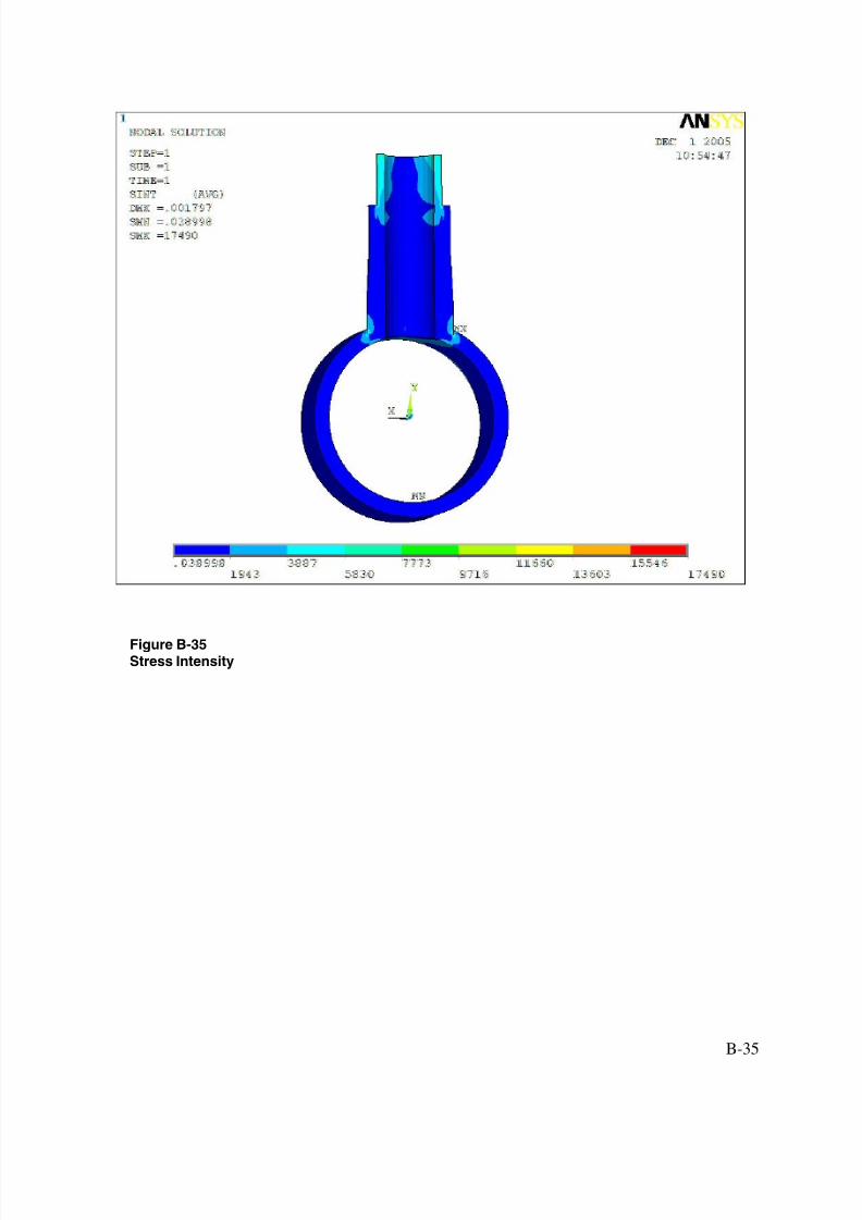
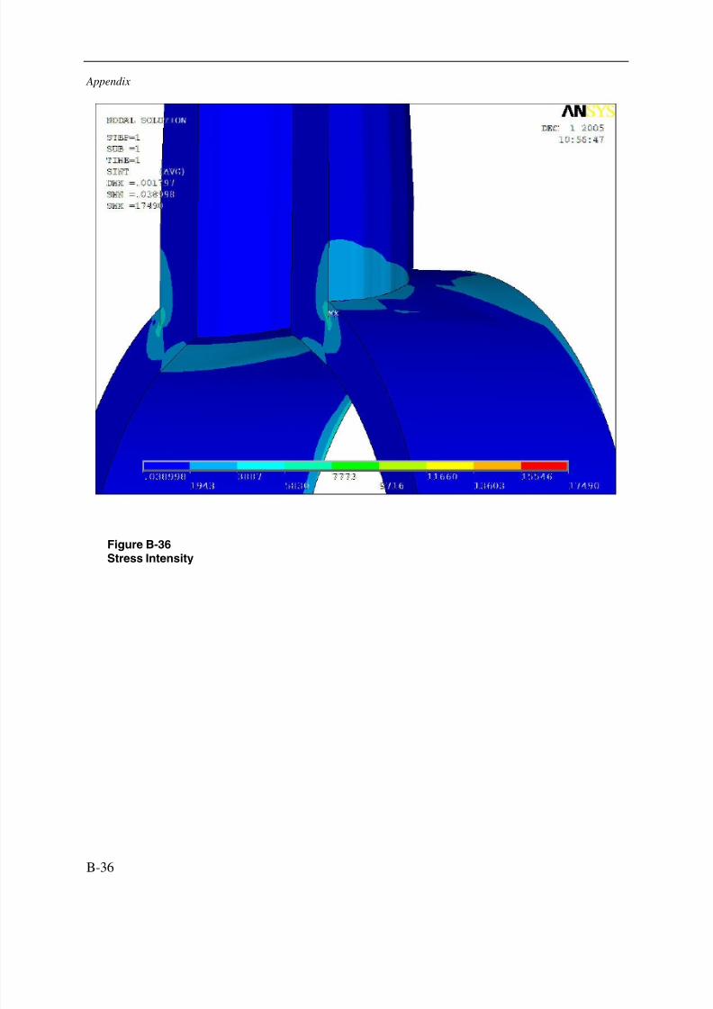
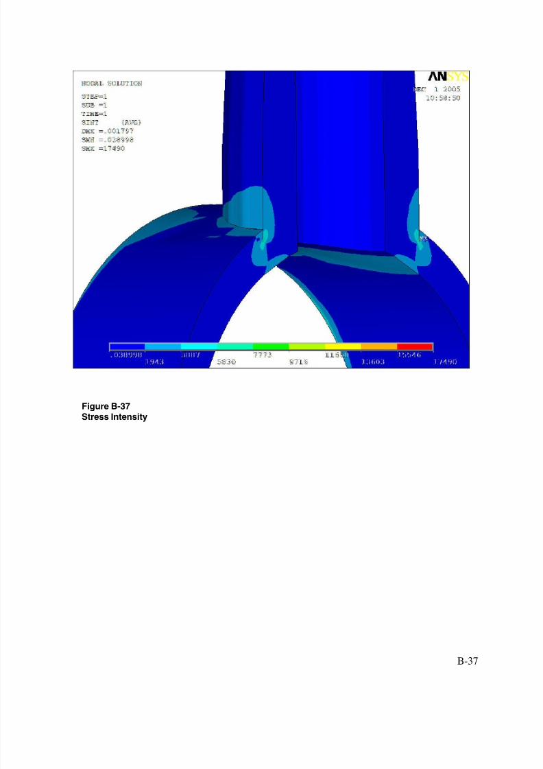
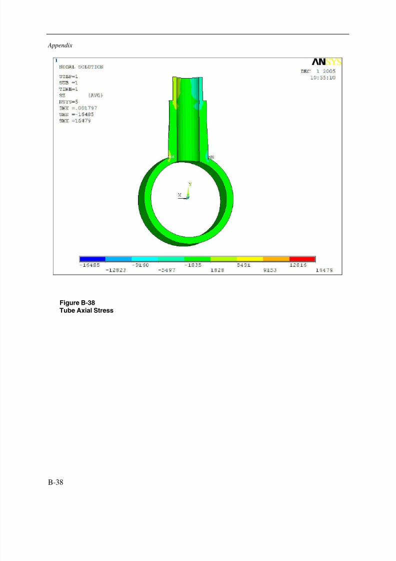
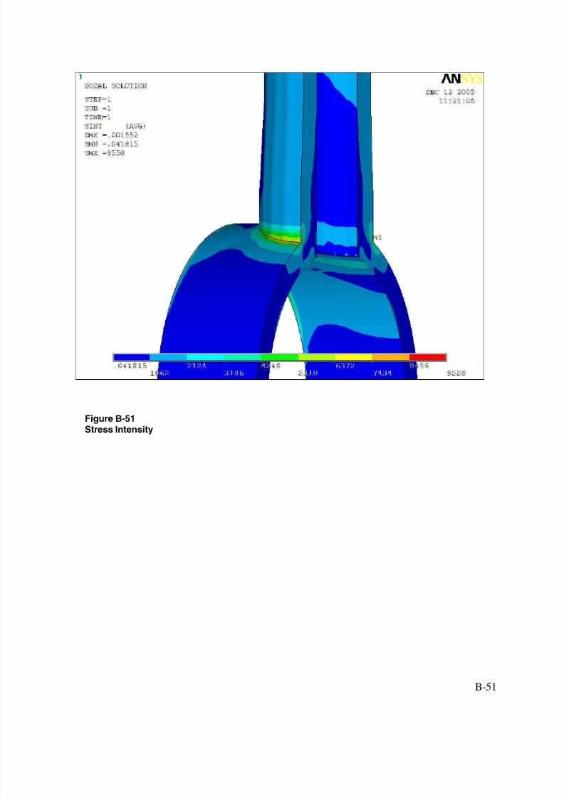
The 1000 in-lbs bending moment maximum and minimum stress values and location of maximum stress are located in Table 3-2. As seen in this table, the stress values for the originalconfiguration and partial penetration designs are very similar. The location of maximum stressfor the original configuration is located at the top of the weld where it meets the tube outerdiameter. For the partial penetration designs, the location is in the gap or lack of weld fusionarea. This is to be expected because of the geometry of the weld and therefore the location of thelack of fusion. Similar to what is noted above for the pressure load, the actual stress
concentration effect at this gap may not be completely captured in the FE results.
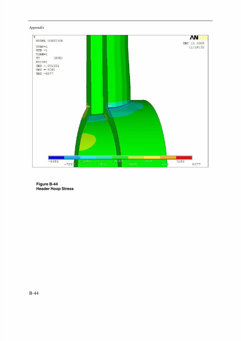
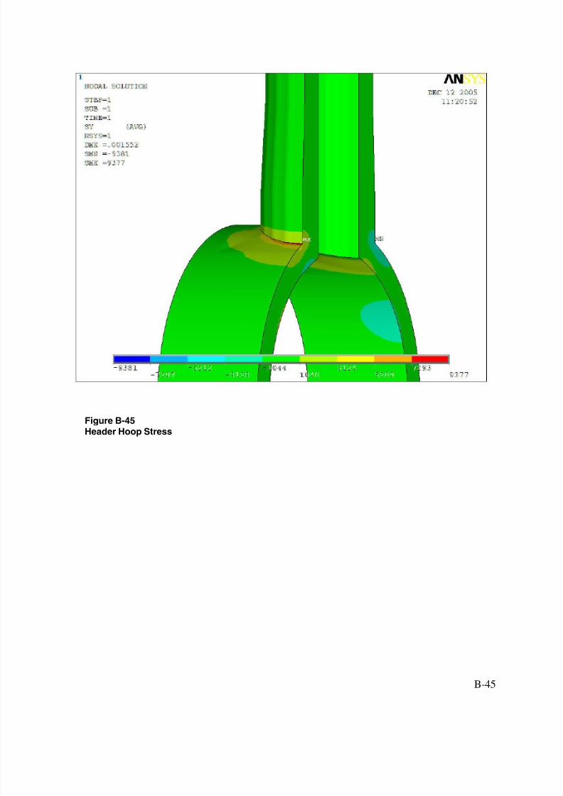
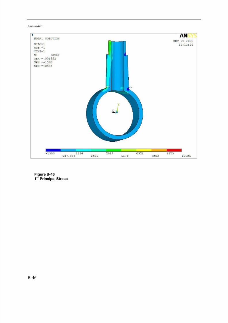
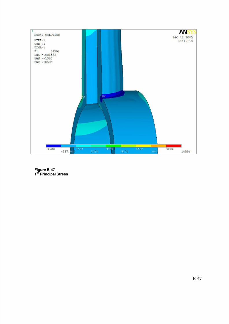
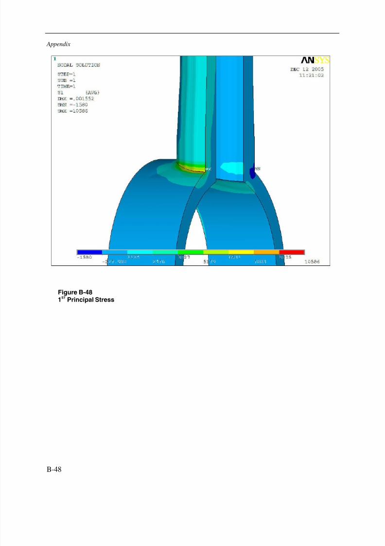
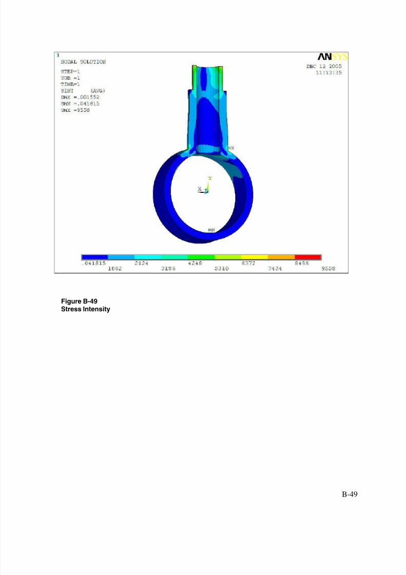
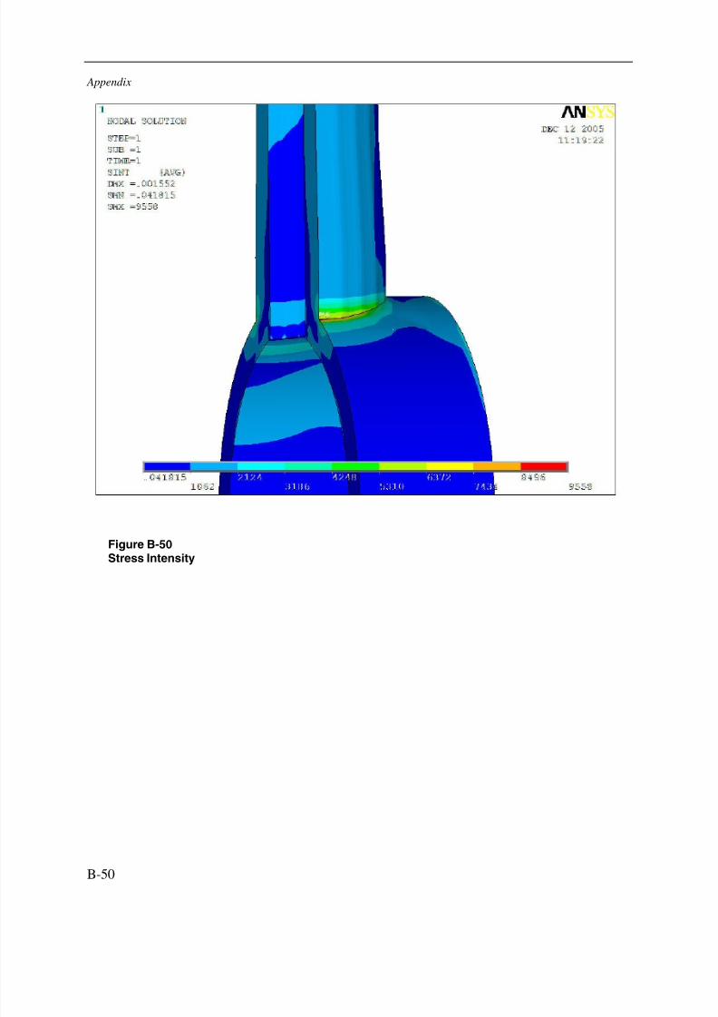
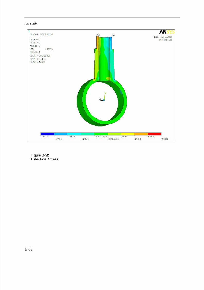
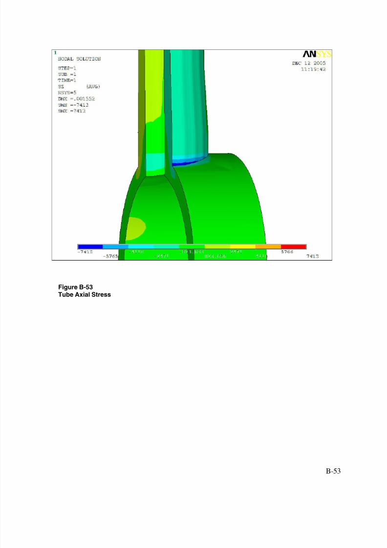
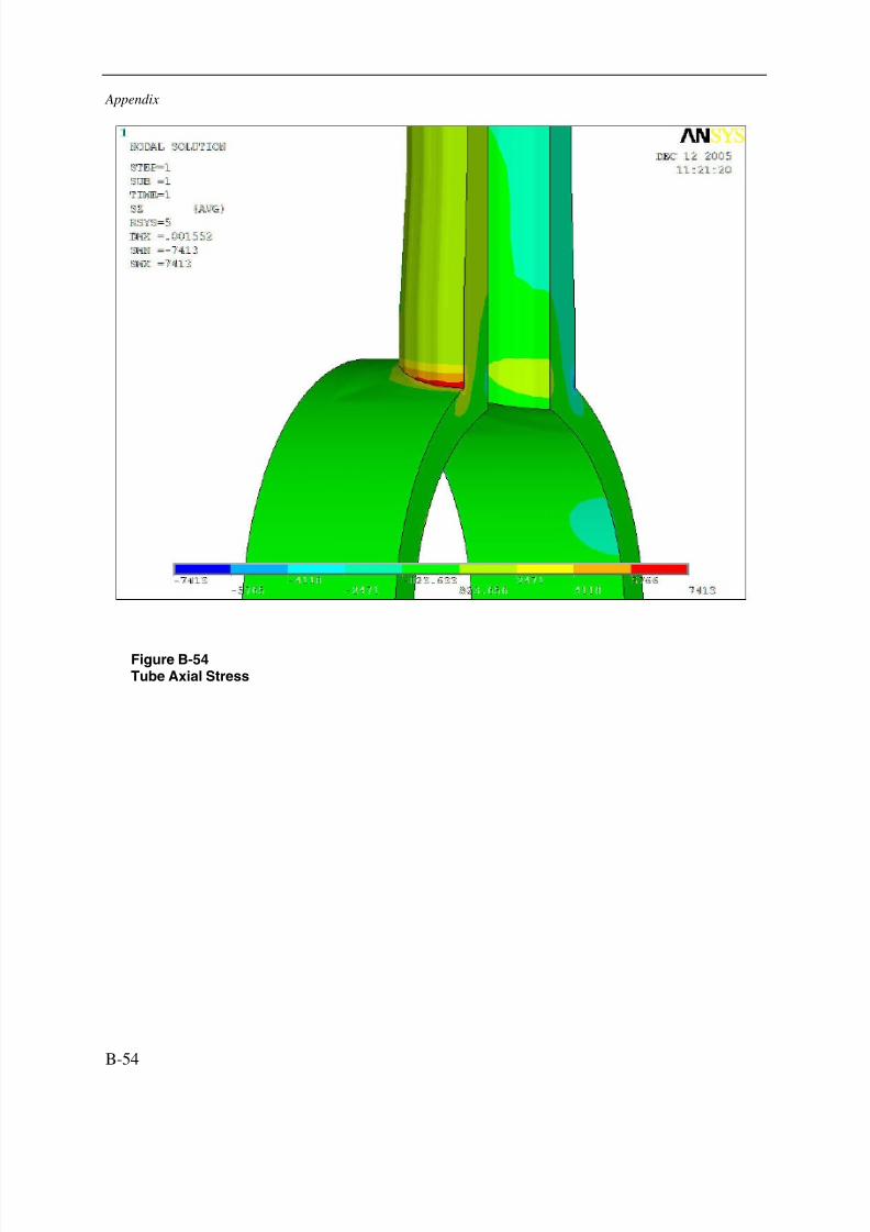
The full penetration configuration shows significantly less stress than the original or repairdesigns. The stress intensity at the maximum location is over 40% less than the other optionsanalyzed. This can be understood by realizing that the only stress riser is the sharp cornerbetween the OD of the tube and the OD of the header. Since there is no lack of weld fusionassociated with the full penetration geometry, this stress concentration is not present in thisdesign Also, the original design has only the thickness of the original tube (0.180”) at thelocation of highest stress as compared to the thickness of the stub tube (0.437”) for the full
3-1
7/29/2019 Devt of Tube Repair Techniques for HR Steam Generators
http://slidepdf.com/reader/full/devt-of-tube-repair-techniques-for-hr-steam-generators 28/140
Results
penetration option. Images that show the results of the bending moment analysis for eachconfiguration are available in Appendix B.
Table 3-1Maximum and Minimum Stresses for Internal Pressure Analysis
Pressure Stress RunStress Comparison Header
Attachment Welds Maximum(ksi)
Minimum(ksi)
Location
Header σhoop
49.2 -4.7 Weld Root at Tube OD (Gap End)
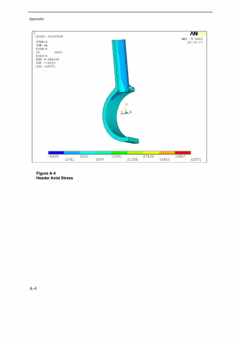
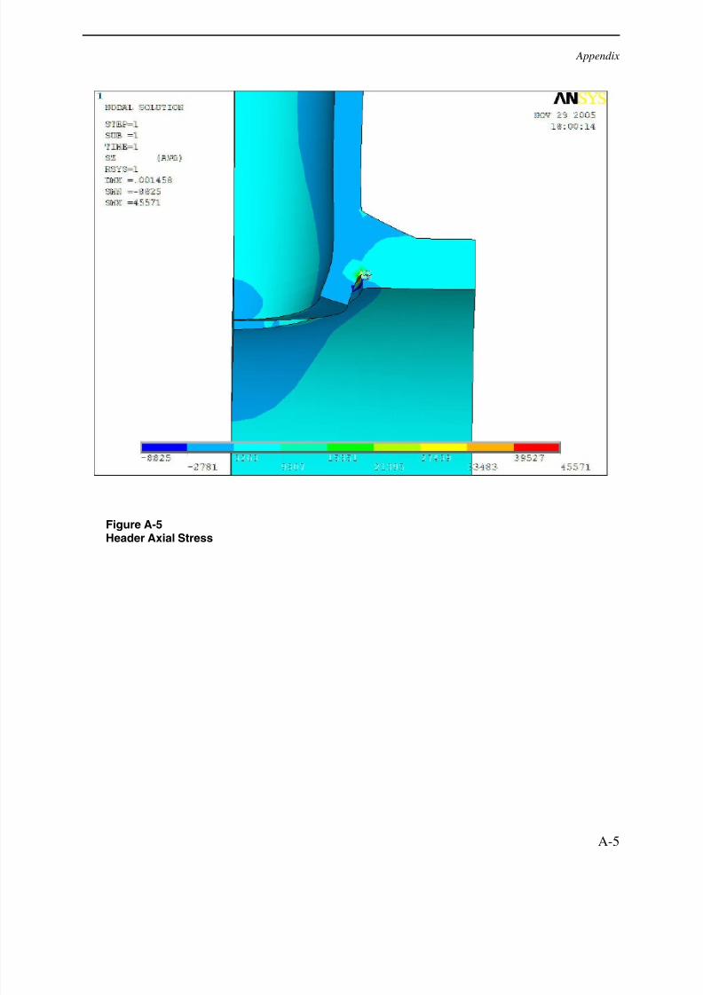
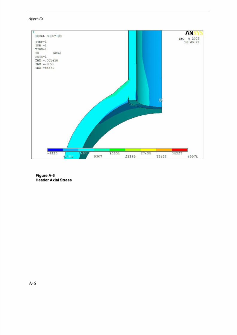
Header σaxial
45.6 -8.8 Weld Root at Tube OD (Gap End)
Principal σ 58.5 1.4 Weld Root at Tube OD (Gap End)
OriginalConfiguration
σINTENSITY
53.6 3.7 Weld Root at Tube OD (Gap End)
Header σhoop
43.3 -5.6 Tube ID at Header ID
Header σaxial
19.0 -2.5 Gap End
Principal σ 46.6 0.0 Gap End
PartialPenetrationRepair
(0.225" WeldDepth)
σINTENSITY
48.5 0.4 Gap End
Header σhoop
43.2 -5.7 Tube ID at Header ID
Header σaxial
19.1 -3.1 Gap End
Principal σ 44.9 0.0 Gap End
PartialPenetration
Repair(0.243" Weld
Depth)σ
INTENSITY46.0 0.4 Gap End
Header σhoop
42.5 -1.8 Tube ID at Header ID
Header σaxial
15.9 -1.8 Intersection Header/Tube
Principal σ 42.5 0.1 Tube ID at Header ID
FullPenetration
Repair
σINTENSITY
43.7 0.4 Tube ID at Header ID
3-2
7/29/2019 Devt of Tube Repair Techniques for HR Steam Generators
http://slidepdf.com/reader/full/devt-of-tube-repair-techniques-for-hr-steam-generators 29/140
Results
Table 3-2Maximum and Minimum Stresses for Bending Moment Analysis
Bending Moment RunStress Comparison Header
Attachment Welds Maximum
(ksi)
Minimum
(ksi)
Location (Max)
Header σhoop 11.5 -11.5 Top of Weld (Tube OD)
Tube σaxial 13.5 -13.5 Top of Weld (Tube OD)
Principal σ 17.4 -2.2 Top of Weld (Tube OD)
OriginalConfiguration
σINTENSITY 16.5 0.0 Top of Weld (Tube OD)
Header σhoop 9.7 -9.7 Gap End
Tube σaxial 16.4 -16.4 Gap End
Principal σ 17.3 -4.2 Gap End
PartialPenetration
Repair
(0.225" WeldDepth)σINTENSITY 17.6 0.0 Gap End
Header σhoop 10.2 -10.2 Gap End
Tube σaxial 16.5 -16.5 Gap End
Principal σ 17.4 -4.4 Gap End
PartialPenetration
Repair (0.243" Weld
Depth)σINTENSITY 17.5 0.0 Gap End
Header σhoop 9.4 -9.4 Intersection Header/Tube
Tube σaxial 7.4 -7.4 Intersection Header/Tube
Principal σ 10.6 -1.6 Intersection Header/Tube
Full
PenetrationRepair
σINTENSITY 9.6 0.0 Intersection Header/Tube
Conclusions and Recommendations
The results of the internal pressure and bending moment runs show similar results. For both,most of the applicable stresses are highest in the original configuration and lowest in the fullpenetration configuration. This is expected as the original configuration has a smaller tubethickness than the stub tube attachment used in the repair options and also a stress concentrationassociated with the lack of fusion on the internal surface.
The especially high stresses seen in the original configuration during the internal pressureanalysis give some potential insight into the failures seen by HRSG operators. The lack of fusionseems to create a significant stress concentration at the end of this gap and therefore could resultin fatigue type cracking. The bending moment application showed no significantly higherstresses for this configuration over the two partial penetration designs, however.
3-3

7/29/2019 Devt of Tube Repair Techniques for HR Steam Generators
http://slidepdf.com/reader/full/devt-of-tube-repair-techniques-for-hr-steam-generators 30/140
Results
3-4
For the repair configurations in the pressure run, it should be noted that all three have verysimilar stress values. The full penetration design has the lowest stresses but the values are notsignificantly different that the two partial penetration options. In the bending moment analysis,however, the full penetration repair does show over 40% less first principal stress and stressintensity than the other three.
After comparing the results of both the internal pressure and bending moment analyses for eachconfiguration, evidence has been established that the replacement of the original header-to-tubeattachment weld with any of the three repair options would reduce stresses for the two conditionsanalyzed in this project. The full penetration option, because it has no lack of fusion, has thelowest stress values of any of the configurations.
7/29/2019 Devt of Tube Repair Techniques for HR Steam Generators
http://slidepdf.com/reader/full/devt-of-tube-repair-techniques-for-hr-steam-generators 31/140
National Board Interpretation 04-15
4 NATIONAL BOARD INTERPRETATION 04-15
Following completion of a header-to-tube repair device described in EPRI Report 1010441,many member utilities asked that we work with ASME Boiler & Pressure Vessel Code and/orthe National Board to make sure the new technology could be readily applied. Severaldiscussions were held with ASME Section I members during the 4
thquarter of 2005. It was
recommended that we further discuss the approach with members of the National Board, sincethe new approach is considered at repair instead of new construction.
National Board members were contacted in November 2005. The primary issue of discussion
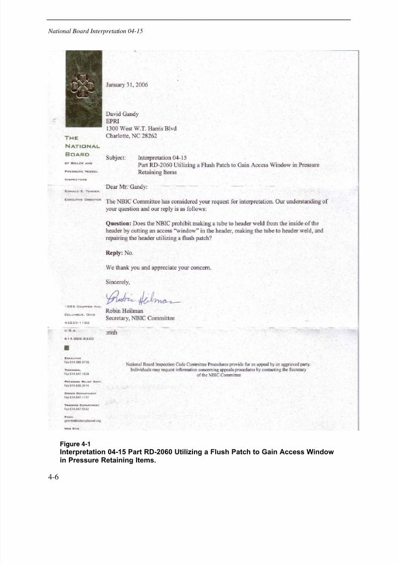
concentrated on whether the ID repair weld configuration was addressed by one of theconfigurations shown in ASME Section I PW-16. EPRI was asked to provide both an overviewof the technology and supporting information (stress analysis data as reported earlier in thisreport) to NBIC in December. Subsequently, EPRI staff attended the January 2006 NBICmeeting to request an “Interpretation” on utilizing the new technology. The Interpretation 04-15was titled: “Part RD-2060 Utilizing a Flush Patch to Gain Access Window in Pressure RetainingItems.” The official documentation for this is shown in Figure 4-1.
With the Interpretation in hand, utilities should now be able to use the header-to-tube repairtechnology to address attachment cracking in the future.
4-5
7/29/2019 Devt of Tube Repair Techniques for HR Steam Generators
http://slidepdf.com/reader/full/devt-of-tube-repair-techniques-for-hr-steam-generators 32/140
National Board Interpretation 04-15
Figure 4-1
Interpretation 04-15 Part RD-2060 Utilizing a Flush Patch to Gain Access Windowin Pressure Retaining Items.
4-6
7/29/2019 Devt of Tube Repair Techniques for HR Steam Generators
http://slidepdf.com/reader/full/devt-of-tube-repair-techniques-for-hr-steam-generators 33/140
Internal Tube Repair
5
INTERNAL TUBE REPAIR
Repair techniques for address two different types of HRSG repairs have been developed andreported in EPRI report 1010441. The techniques include repairs for tube-to-tube applicationsand for tube-to-header attachments. EPRI is continuing development in 2006 and has plans todevelop an internal repair method for HRSG tubing. In December 2005, a request for proposalwas sent out to 10 repair vendors/OEMs to initiate the process for developing the internal tuberepair device. Proposals are expected by February 2006, and work should hopefully get
underway by April 2006. The RFP is provided below:
Request For ProposalInternal Repair For HRSG & Boiler Tubing
Purpose of Work
In recent years, flow accelerated corrosion (FAC) has become a significant problem for heatrecovery steam generator (HRSG) tubing particularly at bends or locations where turbulence hasincreased. Damage can occur anywhere along the tube length and with time can result in tubeleakage or blowout. Such failures are costly not only in terms of repair, but also in terms of lostavailability of the plant.
EPRI is currently developing inspection technologies that will enable power producers toexamine tubes at various locations along the tube length. Assuming FAC damage can be locatedusing this technology, an effective method to perform the repair is needed. The purpose of thisRequest for Proposal is to solicit proposals for the development of an Internal Welding RepairDevice (IWRD) for HRSG and Boiler tubing which can be inserted from one end of the tube,transferred along the tube positioned at the exact location of the damage, and used to perform an
ID weld buildup at that location.
Statement of Work
The Internal Welding Repair Device should make use of the gas tungsten arc welding (GTAW),gas metal arc welding (GMAW) or laser beam welding (LBW) process and should be capable of performing a weld buildup at a location along an HRSG tube or a boiler tube. The device should
5-7
7/29/2019 Devt of Tube Repair Techniques for HR Steam Generators
http://slidepdf.com/reader/full/devt-of-tube-repair-techniques-for-hr-steam-generators 34/140
Internal Tube Repair
be capable of insertion from within a header tube bore location allowing it to be pushed (fromlower header) or dropped (from upper header) to the repair location. Access to the bore regioncan be accomplished by removal of an access port (hole) 180 degrees opposite the bore region of the header.
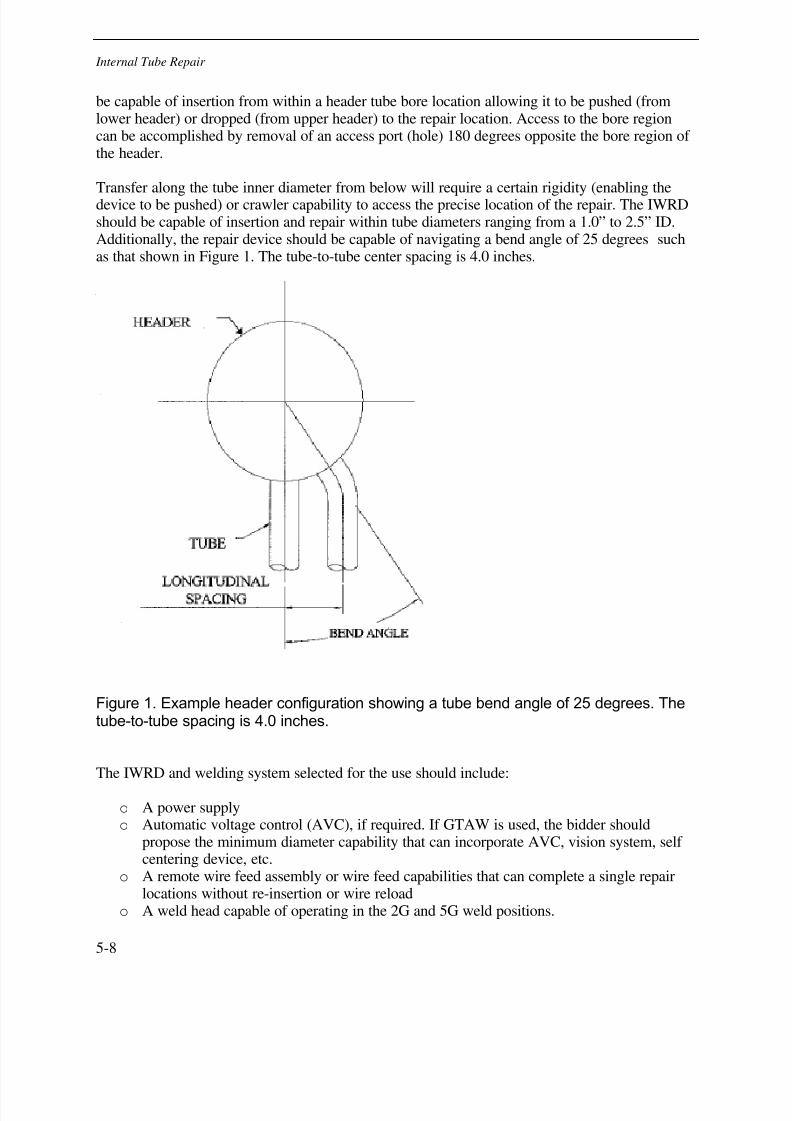
Transfer along the tube inner diameter from below will require a certain rigidity (enabling thedevice to be pushed) or crawler capability to access the precise location of the repair. The IWRDshould be capable of insertion and repair within tube diameters ranging from a 1.0” to 2.5” ID.Additionally, the repair device should be capable of navigating a bend angle of 25 degrees suchas that shown in Figure 1. The tube-to-tube center spacing is 4.0 inches.
Figure 1. Example header configuration showing a tube bend angle of 25 degrees. Thetube-to-tube spacing is 4.0 inches.
The IWRD and welding system selected for the use should include:
o A power supplyo Automatic voltage control (AVC), if required. If GTAW is used, the bidder should
propose the minimum diameter capability that can incorporate AVC, vision system, self centering device, etc.
o A remote wire feed assembly or wire feed capabilities that can complete a single repairlocations without re-insertion or wire reload
o A weld head capable of operating in the 2G and 5G weld positions.
5-8
7/29/2019 Devt of Tube Repair Techniques for HR Steam Generators
http://slidepdf.com/reader/full/devt-of-tube-repair-techniques-for-hr-steam-generators 35/140
Internal Tube Repair
o A video probe vision system that provides real-time monitoring of the weld puddle.o A clamping device to center the IWRD at the precise repair location
The RFP should address the following questions:
o How will the tube ID be cleaned/machined/ground prior to welding?o How will the wire be fed to push it over a distance of 50-100ft?o What happens if the tungsten sticks during welding (GTAW process only)? What
additional tooling would be required for rework if the tungsten should stick?o What diameter of wire will be used for the IWRD process?o What video probe vision system will be incorporated into the IWRD system.o How will the final surface be prepared to minimize flow disruptions within the tube
which often lead to a second failure? A detailed specification stipulating surfaceroughness and buildup (reinforcement) will be required in final system.
HRSG Tube Specifications
o Tube ID – 1.0” to 3.0” IDo Tube thickness > 0.125”To Distance IWRD must be inserted into tube to perform repairs:
o If push/pull system, 0-50fto If push only, 0-100fto If pull only, 0-100ft.
o Bend Angle (around dog leg) is 25 degrees—See Figure 1.o Tube spacing (center-to-center) is 4.0 inches.
Period of Performance
The period of performance will be April 2006 to December 2007. Several individualdemonstrations of the IWRD systems capabilities will be required at specified intervals as shownin the Schedule below.
Schedule & Demonstration
EPRI will perform metallography and radiography to assess performance of the selectedcontractor’s ability to meet the following schedule and welding demonstrations.
o Contractor will demonstrate ID tube welding capability on a 1” and 3” diameter tube at adistance of 5 feet from insertion of IWRD on a straight tube. (December 2006)
o Contractor will demonstrate ID tube welding capability on a 1”and 3” diameter tube at adistance of 50 feet from insertion of IWRD (April 2007)
o Contractor will demonstrate ID tube welding capability on a 1” and 3” diameter tube witha radius as shown in Figure 1 at a distance of 50 feet from insertion of IWRD (August2007)
5-9

7/29/2019 Devt of Tube Repair Techniques for HR Steam Generators
http://slidepdf.com/reader/full/devt-of-tube-repair-techniques-for-hr-steam-generators 36/140
Internal Tube Repair
o Contractor will demonstrate ID tube welding capability on a 1” and 3” diameter tube witha radius as shown in Figure 1 at a distance of 50 feet from insertion of IRD (December2007)
Successful demonstration of each of the above will be considered when the contractor meets bothmetallography and radiography requirements.
Cost Information
Cost-sharing of the IRWD development is encouraged. The proposal should include potentialcost-sharing arrangements that apply to the bidder. Cost sharing will be considered for licensingagreements. EPRI will reward one contract; subcontracting is allowed, although the bidder willbe responsible for subcontracted work.
EPRI Project Manager
David Gandy
Commercialization Plan
The bidder is to propose a commercialization plan.
Evaluation Criteria
See Attachment 1.
List of Invitees
a) Arc Machines, Incb) Polyseude-Astro Arcc) Liburidi-Dimetricsd) Encompass Machines, Ince) Magnatechf) Aggressive Equipmentg) Welding Services, Inc.
h) PCI Energyi) Areva j) GE Services
5-10
7/29/2019 Devt of Tube Repair Techniques for HR Steam Generators
http://slidepdf.com/reader/full/devt-of-tube-repair-techniques-for-hr-steam-generators 37/140
A APPENDIX
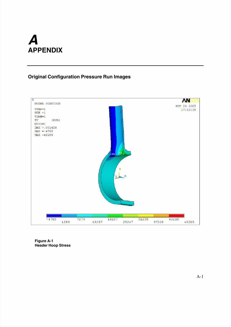
Original Configuration Pressure Run Images
Figure A-1Header Hoop Stress
A-1

7/29/2019 Devt of Tube Repair Techniques for HR Steam Generators
http://slidepdf.com/reader/full/devt-of-tube-repair-techniques-for-hr-steam-generators 38/140
Appendix
Figure A-2Header Hoop Stress
A-2
7/29/2019 Devt of Tube Repair Techniques for HR Steam Generators
http://slidepdf.com/reader/full/devt-of-tube-repair-techniques-for-hr-steam-generators 39/140
Appendix
Figure A-3Header Hoop Stress
A-3
7/29/2019 Devt of Tube Repair Techniques for HR Steam Generators
http://slidepdf.com/reader/full/devt-of-tube-repair-techniques-for-hr-steam-generators 40/140
Appendix
Figure A-4
Header Axial Stress
A-4
7/29/2019 Devt of Tube Repair Techniques for HR Steam Generators
http://slidepdf.com/reader/full/devt-of-tube-repair-techniques-for-hr-steam-generators 41/140
Appendix
Figure A-5Header Axial Stress
A-5
7/29/2019 Devt of Tube Repair Techniques for HR Steam Generators
http://slidepdf.com/reader/full/devt-of-tube-repair-techniques-for-hr-steam-generators 42/140
Appendix
Figure A-6Header Axial Stress
A-6
7/29/2019 Devt of Tube Repair Techniques for HR Steam Generators
http://slidepdf.com/reader/full/devt-of-tube-repair-techniques-for-hr-steam-generators 43/140
Appendix
Figure A-71
stPrincipal Stress
A-7

7/29/2019 Devt of Tube Repair Techniques for HR Steam Generators
http://slidepdf.com/reader/full/devt-of-tube-repair-techniques-for-hr-steam-generators 44/140
Appendix
Figure A-81
stPrincipal Stress
A-8

7/29/2019 Devt of Tube Repair Techniques for HR Steam Generators
http://slidepdf.com/reader/full/devt-of-tube-repair-techniques-for-hr-steam-generators 45/140
Appendix
Figure A-91
stPrincipal Stress
A-9

7/29/2019 Devt of Tube Repair Techniques for HR Steam Generators
http://slidepdf.com/reader/full/devt-of-tube-repair-techniques-for-hr-steam-generators 46/140
Appendix
Figure A-10Stress Intensity
A-10
7/29/2019 Devt of Tube Repair Techniques for HR Steam Generators
http://slidepdf.com/reader/full/devt-of-tube-repair-techniques-for-hr-steam-generators 47/140
Appendix
Figure A-11Stress Intensity
A-11
7/29/2019 Devt of Tube Repair Techniques for HR Steam Generators
http://slidepdf.com/reader/full/devt-of-tube-repair-techniques-for-hr-steam-generators 48/140
Appendix
Figure A-12Stress Intensity
A-12
7/29/2019 Devt of Tube Repair Techniques for HR Steam Generators
http://slidepdf.com/reader/full/devt-of-tube-repair-techniques-for-hr-steam-generators 49/140
Appendix
Partial Penetration (0.225” Weld Depth) Pressure Run Images
Figure A-13Header Hoop Stress
A-13
7/29/2019 Devt of Tube Repair Techniques for HR Steam Generators
http://slidepdf.com/reader/full/devt-of-tube-repair-techniques-for-hr-steam-generators 50/140
Appendix
Figure A-14Header Hoop Stress
A-14
7/29/2019 Devt of Tube Repair Techniques for HR Steam Generators
http://slidepdf.com/reader/full/devt-of-tube-repair-techniques-for-hr-steam-generators 51/140
Appendix
Figure A-15Header Hoop Stress
A-15
7/29/2019 Devt of Tube Repair Techniques for HR Steam Generators
http://slidepdf.com/reader/full/devt-of-tube-repair-techniques-for-hr-steam-generators 52/140
Appendix
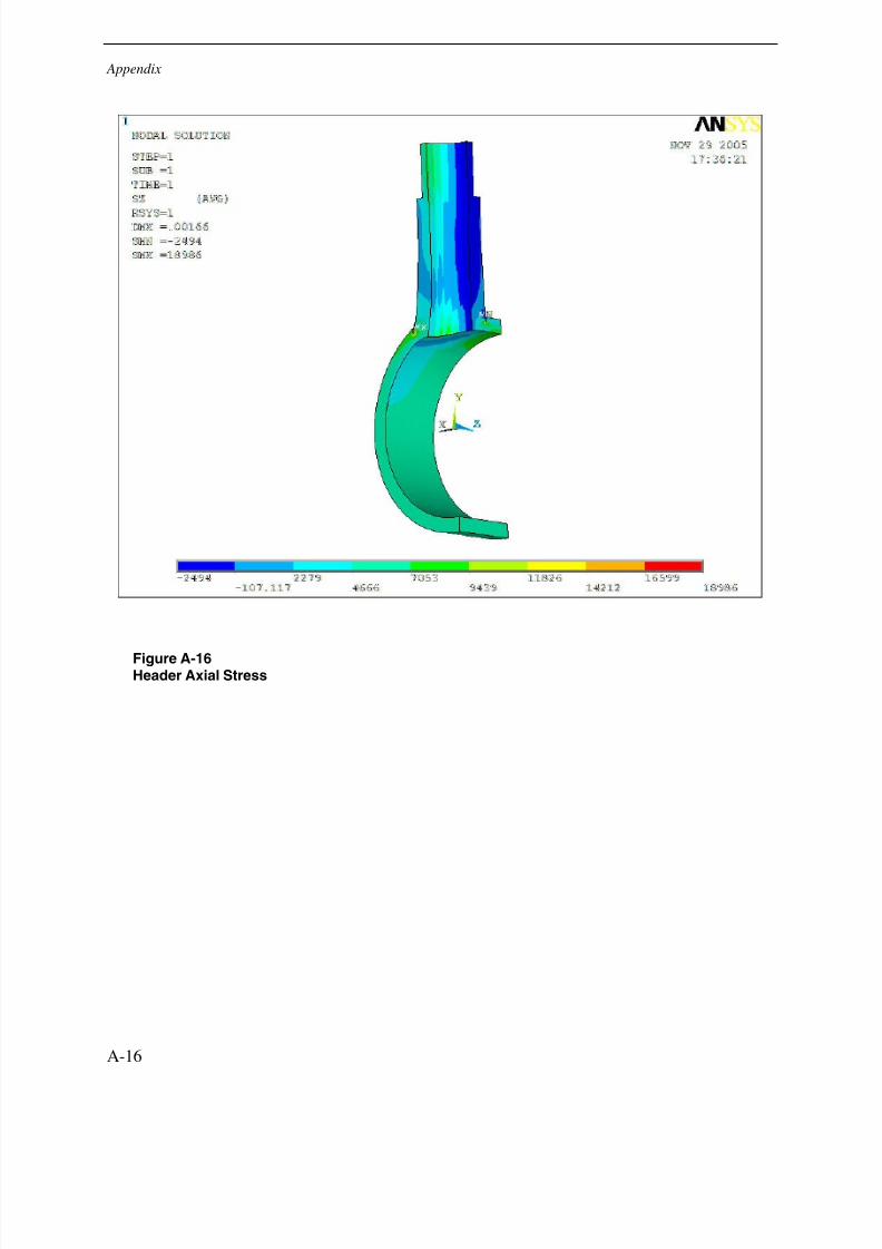
Figure A-16Header Axial Stress
A-16
7/29/2019 Devt of Tube Repair Techniques for HR Steam Generators
http://slidepdf.com/reader/full/devt-of-tube-repair-techniques-for-hr-steam-generators 53/140
Appendix
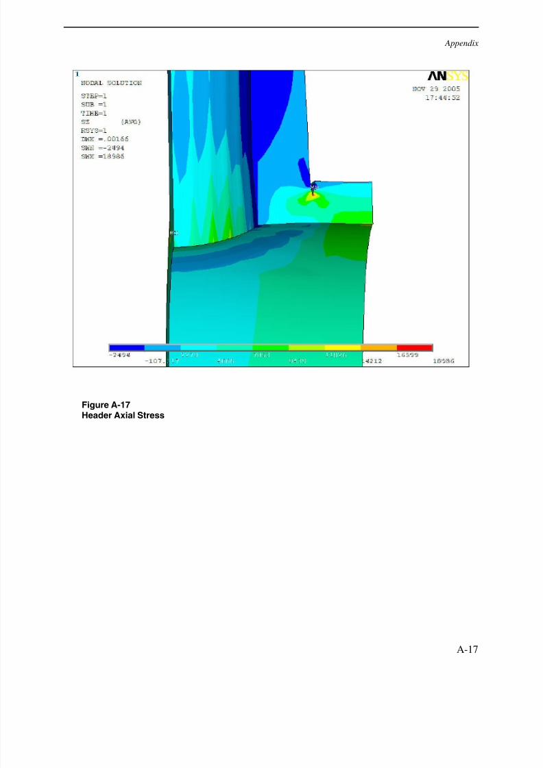
Figure A-17Header Axial Stress
A-17
7/29/2019 Devt of Tube Repair Techniques for HR Steam Generators
http://slidepdf.com/reader/full/devt-of-tube-repair-techniques-for-hr-steam-generators 54/140
Appendix
Figure A-18Header Axial Stress
A-18
7/29/2019 Devt of Tube Repair Techniques for HR Steam Generators
http://slidepdf.com/reader/full/devt-of-tube-repair-techniques-for-hr-steam-generators 55/140
Appendix
Figure A-191
stPrincipal Stress
A-19
7/29/2019 Devt of Tube Repair Techniques for HR Steam Generators
http://slidepdf.com/reader/full/devt-of-tube-repair-techniques-for-hr-steam-generators 56/140
Appendix
Figure A-201
stPrincipal Stress
A-20
7/29/2019 Devt of Tube Repair Techniques for HR Steam Generators
http://slidepdf.com/reader/full/devt-of-tube-repair-techniques-for-hr-steam-generators 57/140
Appendix
Figure A-211
stPrincipal Stress
A-21
7/29/2019 Devt of Tube Repair Techniques for HR Steam Generators
http://slidepdf.com/reader/full/devt-of-tube-repair-techniques-for-hr-steam-generators 58/140
Appendix
Figure A-22Stress Intensity
A-22
7/29/2019 Devt of Tube Repair Techniques for HR Steam Generators
http://slidepdf.com/reader/full/devt-of-tube-repair-techniques-for-hr-steam-generators 59/140
Appendix
Figure A-23Stress Intensity
A-23
7/29/2019 Devt of Tube Repair Techniques for HR Steam Generators
http://slidepdf.com/reader/full/devt-of-tube-repair-techniques-for-hr-steam-generators 60/140
Appendix
Figure A-24Stress Intensity
A-24
7/29/2019 Devt of Tube Repair Techniques for HR Steam Generators
http://slidepdf.com/reader/full/devt-of-tube-repair-techniques-for-hr-steam-generators 61/140
Appendix
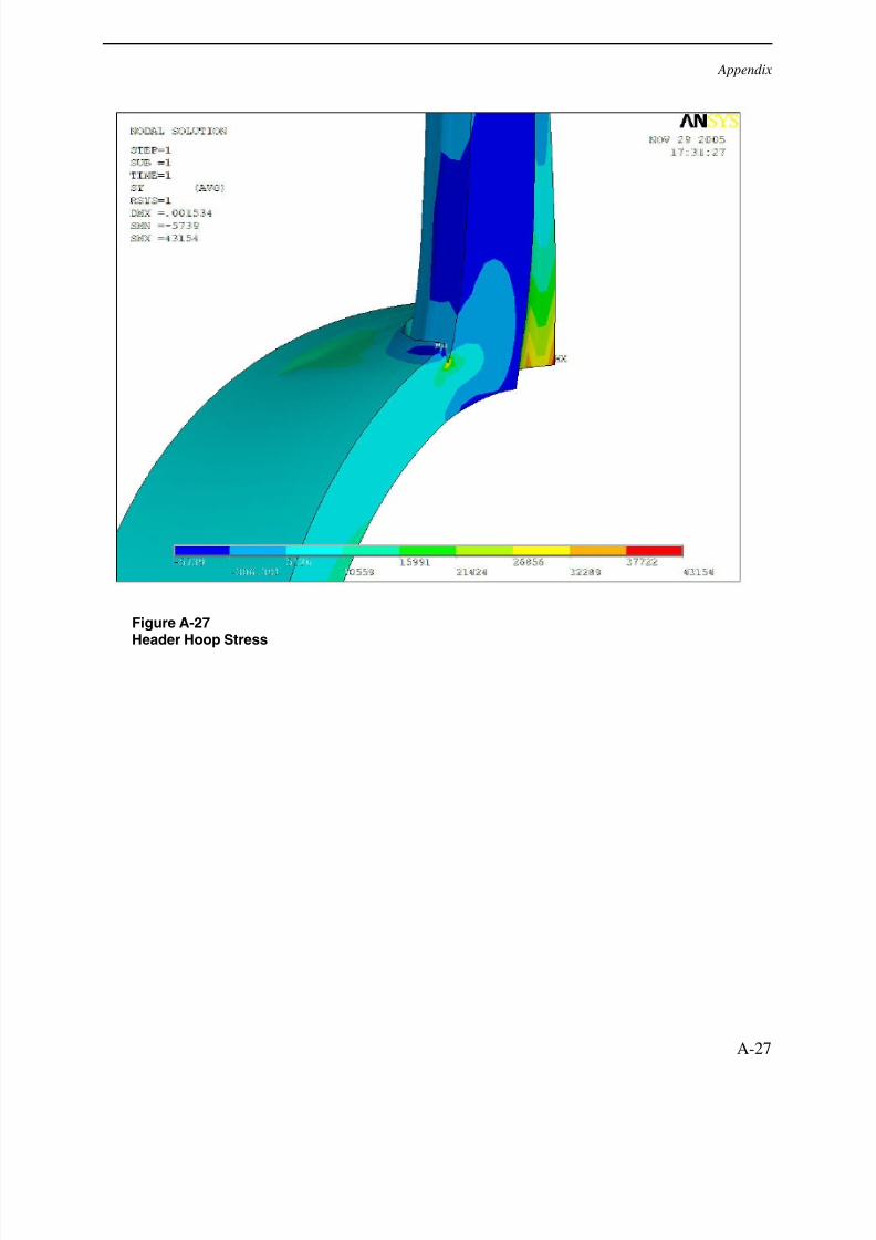
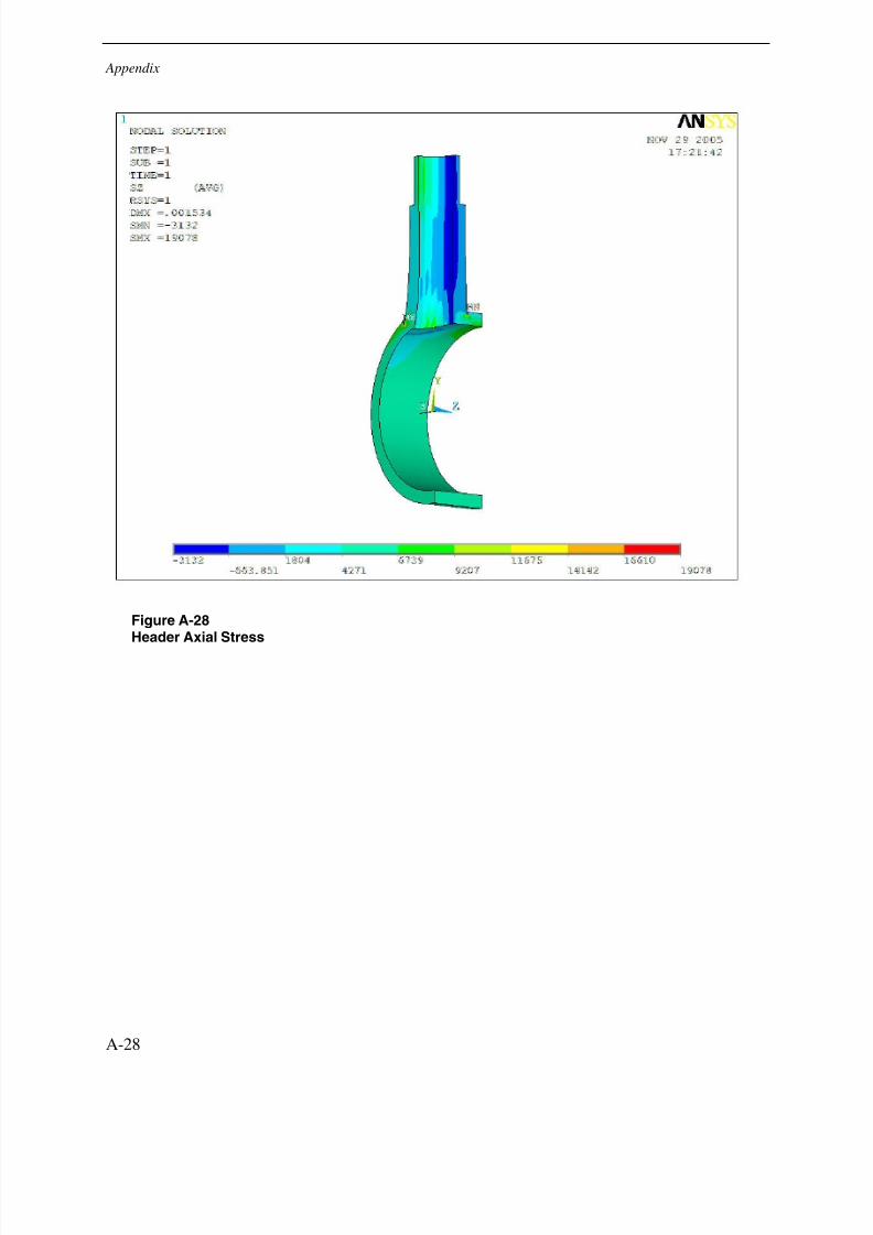
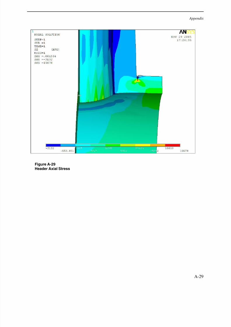
Partial Penetration (0.243” Weld Depth) Pressure Run Images
Figure A-25Header Hoop Stress
A-25
7/29/2019 Devt of Tube Repair Techniques for HR Steam Generators
http://slidepdf.com/reader/full/devt-of-tube-repair-techniques-for-hr-steam-generators 62/140
Appendix
Figure A-26Header Hoop Stress
A-26
7/29/2019 Devt of Tube Repair Techniques for HR Steam Generators
http://slidepdf.com/reader/full/devt-of-tube-repair-techniques-for-hr-steam-generators 63/140
Appendix
Figure A-27Header Hoop Stress
A-27
7/29/2019 Devt of Tube Repair Techniques for HR Steam Generators
http://slidepdf.com/reader/full/devt-of-tube-repair-techniques-for-hr-steam-generators 64/140
Appendix
Figure A-28Header Axial Stress
A-28
7/29/2019 Devt of Tube Repair Techniques for HR Steam Generators
http://slidepdf.com/reader/full/devt-of-tube-repair-techniques-for-hr-steam-generators 65/140
Appendix
Figure A-29Header Axial Stress
A-29
7/29/2019 Devt of Tube Repair Techniques for HR Steam Generators
http://slidepdf.com/reader/full/devt-of-tube-repair-techniques-for-hr-steam-generators 66/140
Appendix
Figure A-30Header Axial Stress
A-30

7/29/2019 Devt of Tube Repair Techniques for HR Steam Generators
http://slidepdf.com/reader/full/devt-of-tube-repair-techniques-for-hr-steam-generators 67/140
Appendix
Figure A-311
stPrincipal Stress
A-31
7/29/2019 Devt of Tube Repair Techniques for HR Steam Generators
http://slidepdf.com/reader/full/devt-of-tube-repair-techniques-for-hr-steam-generators 68/140
Appendix
Figure A-321
stPrincipal Stress
A-32
7/29/2019 Devt of Tube Repair Techniques for HR Steam Generators
http://slidepdf.com/reader/full/devt-of-tube-repair-techniques-for-hr-steam-generators 69/140
Appendix
Figure A-331
stPrincipal Stress
A-33
7/29/2019 Devt of Tube Repair Techniques for HR Steam Generators
http://slidepdf.com/reader/full/devt-of-tube-repair-techniques-for-hr-steam-generators 70/140
Appendix
Figure A-34Stress Intensity
A-34
7/29/2019 Devt of Tube Repair Techniques for HR Steam Generators
http://slidepdf.com/reader/full/devt-of-tube-repair-techniques-for-hr-steam-generators 71/140
Appendix
Figure A-35Stress Intensity
A-35
7/29/2019 Devt of Tube Repair Techniques for HR Steam Generators
http://slidepdf.com/reader/full/devt-of-tube-repair-techniques-for-hr-steam-generators 72/140
Appendix
Figure A-36Stress Intensity
A-36
7/29/2019 Devt of Tube Repair Techniques for HR Steam Generators
http://slidepdf.com/reader/full/devt-of-tube-repair-techniques-for-hr-steam-generators 73/140
Appendix
Full Penetration Pressure Run Images
Figure A-37Header Hoop Stress
A-37
7/29/2019 Devt of Tube Repair Techniques for HR Steam Generators
http://slidepdf.com/reader/full/devt-of-tube-repair-techniques-for-hr-steam-generators 74/140
Appendix
Figure A-38Header Hoop Stress
A-38

7/29/2019 Devt of Tube Repair Techniques for HR Steam Generators
http://slidepdf.com/reader/full/devt-of-tube-repair-techniques-for-hr-steam-generators 75/140
Appendix
Figure A-39Header Hoop Stress
A-39
7/29/2019 Devt of Tube Repair Techniques for HR Steam Generators
http://slidepdf.com/reader/full/devt-of-tube-repair-techniques-for-hr-steam-generators 76/140
Appendix
Figure A-40Header Axial Stress
A-40
7/29/2019 Devt of Tube Repair Techniques for HR Steam Generators
http://slidepdf.com/reader/full/devt-of-tube-repair-techniques-for-hr-steam-generators 77/140
Appendix
Figure A-41Header Axial Stress
A-41
7/29/2019 Devt of Tube Repair Techniques for HR Steam Generators
http://slidepdf.com/reader/full/devt-of-tube-repair-techniques-for-hr-steam-generators 78/140
Appendix
Figure A-42Header Axial Stress
A-42
7/29/2019 Devt of Tube Repair Techniques for HR Steam Generators
http://slidepdf.com/reader/full/devt-of-tube-repair-techniques-for-hr-steam-generators 79/140
Appendix
Figure A-431
stPrincipal Stress
A-43
7/29/2019 Devt of Tube Repair Techniques for HR Steam Generators
http://slidepdf.com/reader/full/devt-of-tube-repair-techniques-for-hr-steam-generators 80/140
Appendix
Figure A-441
stPrincipal Stress
A-44
7/29/2019 Devt of Tube Repair Techniques for HR Steam Generators
http://slidepdf.com/reader/full/devt-of-tube-repair-techniques-for-hr-steam-generators 81/140
Appendix
Figure A-451
stPrincipal Stress
A-45
7/29/2019 Devt of Tube Repair Techniques for HR Steam Generators
http://slidepdf.com/reader/full/devt-of-tube-repair-techniques-for-hr-steam-generators 82/140
Appendix
Figure A-46Stress Intensity
A-46

7/29/2019 Devt of Tube Repair Techniques for HR Steam Generators
http://slidepdf.com/reader/full/devt-of-tube-repair-techniques-for-hr-steam-generators 83/140
Appendix
Figure A-47Stress Intensity
A-47
7/29/2019 Devt of Tube Repair Techniques for HR Steam Generators
http://slidepdf.com/reader/full/devt-of-tube-repair-techniques-for-hr-steam-generators 84/140
Appendix
Figure A-48Stress Intensity
A-48

7/29/2019 Devt of Tube Repair Techniques for HR Steam Generators
http://slidepdf.com/reader/full/devt-of-tube-repair-techniques-for-hr-steam-generators 85/140
B APPENDIX
Original Configuration Bending Moment Analysis Images
Figure B-1Header Hoop Stress
B-1
7/29/2019 Devt of Tube Repair Techniques for HR Steam Generators
http://slidepdf.com/reader/full/devt-of-tube-repair-techniques-for-hr-steam-generators 86/140
Appendix
Figure B-2Header Hoop Stress
B-2
7/29/2019 Devt of Tube Repair Techniques for HR Steam Generators
http://slidepdf.com/reader/full/devt-of-tube-repair-techniques-for-hr-steam-generators 87/140
Figure B-3Header Hoop Stress
B-3
7/29/2019 Devt of Tube Repair Techniques for HR Steam Generators
http://slidepdf.com/reader/full/devt-of-tube-repair-techniques-for-hr-steam-generators 88/140
Appendix
Figure B-41
stPrincipal Stress
B-4
7/29/2019 Devt of Tube Repair Techniques for HR Steam Generators
http://slidepdf.com/reader/full/devt-of-tube-repair-techniques-for-hr-steam-generators 89/140
Figure B-51
stPrincipal Stress
B-5
7/29/2019 Devt of Tube Repair Techniques for HR Steam Generators
http://slidepdf.com/reader/full/devt-of-tube-repair-techniques-for-hr-steam-generators 90/140
Appendix
Figure B-61
stPrincipal Stress
B-6
7/29/2019 Devt of Tube Repair Techniques for HR Steam Generators
http://slidepdf.com/reader/full/devt-of-tube-repair-techniques-for-hr-steam-generators 91/140
Figure B-7Stress Intensity
B-7
7/29/2019 Devt of Tube Repair Techniques for HR Steam Generators
http://slidepdf.com/reader/full/devt-of-tube-repair-techniques-for-hr-steam-generators 92/140
Appendix
Figure B-8Stress Intensity
B-8
7/29/2019 Devt of Tube Repair Techniques for HR Steam Generators
http://slidepdf.com/reader/full/devt-of-tube-repair-techniques-for-hr-steam-generators 93/140
Figure B-9Stress Intensity
B-9
7/29/2019 Devt of Tube Repair Techniques for HR Steam Generators
http://slidepdf.com/reader/full/devt-of-tube-repair-techniques-for-hr-steam-generators 94/140
Appendix
Figure B-10Tube Axial Stress
B-10
7/29/2019 Devt of Tube Repair Techniques for HR Steam Generators
http://slidepdf.com/reader/full/devt-of-tube-repair-techniques-for-hr-steam-generators 95/140
Figure B-11Tube Axial Stress
B-11
7/29/2019 Devt of Tube Repair Techniques for HR Steam Generators
http://slidepdf.com/reader/full/devt-of-tube-repair-techniques-for-hr-steam-generators 96/140
Appendix
Figure B-12Tube Axial Stress
B-12

7/29/2019 Devt of Tube Repair Techniques for HR Steam Generators
http://slidepdf.com/reader/full/devt-of-tube-repair-techniques-for-hr-steam-generators 97/140
Figure B-13Tube Axial Stress
B-13
7/29/2019 Devt of Tube Repair Techniques for HR Steam Generators
http://slidepdf.com/reader/full/devt-of-tube-repair-techniques-for-hr-steam-generators 98/140
Appendix
Figure B-14Tube Hoop Stress
B-14
7/29/2019 Devt of Tube Repair Techniques for HR Steam Generators
http://slidepdf.com/reader/full/devt-of-tube-repair-techniques-for-hr-steam-generators 99/140
Partial Penetration (0.225” Weld Depth) Bending Moment Analysis Images
Figure B-15Header Hoop Stress
B-15
7/29/2019 Devt of Tube Repair Techniques for HR Steam Generators
http://slidepdf.com/reader/full/devt-of-tube-repair-techniques-for-hr-steam-generators 100/140
Appendix
Figure B-16Header Hoop Stress
B-16
7/29/2019 Devt of Tube Repair Techniques for HR Steam Generators
http://slidepdf.com/reader/full/devt-of-tube-repair-techniques-for-hr-steam-generators 101/140
Figure B-17Header Hoop Stres
B-17
7/29/2019 Devt of Tube Repair Techniques for HR Steam Generators
http://slidepdf.com/reader/full/devt-of-tube-repair-techniques-for-hr-steam-generators 102/140
Appendix
Figure B-181
stPrincipal Stress
B-18
7/29/2019 Devt of Tube Repair Techniques for HR Steam Generators
http://slidepdf.com/reader/full/devt-of-tube-repair-techniques-for-hr-steam-generators 103/140
Figure B-191
stPrincipal Stress
B-19
7/29/2019 Devt of Tube Repair Techniques for HR Steam Generators
http://slidepdf.com/reader/full/devt-of-tube-repair-techniques-for-hr-steam-generators 104/140
Appendix
Figure B-201
stPrincipal Stress
B-20
7/29/2019 Devt of Tube Repair Techniques for HR Steam Generators
http://slidepdf.com/reader/full/devt-of-tube-repair-techniques-for-hr-steam-generators 105/140
Figure B-21Stress Intensity
B-21
7/29/2019 Devt of Tube Repair Techniques for HR Steam Generators
http://slidepdf.com/reader/full/devt-of-tube-repair-techniques-for-hr-steam-generators 106/140
Appendix
Figure B-22Stress Intensity
B-22
7/29/2019 Devt of Tube Repair Techniques for HR Steam Generators
http://slidepdf.com/reader/full/devt-of-tube-repair-techniques-for-hr-steam-generators 107/140
Figure B-23Stress Intensity
B-23
7/29/2019 Devt of Tube Repair Techniques for HR Steam Generators
http://slidepdf.com/reader/full/devt-of-tube-repair-techniques-for-hr-steam-generators 108/140
Appendix
Figure B-24Tube Axial Stress
B-24
7/29/2019 Devt of Tube Repair Techniques for HR Steam Generators
http://slidepdf.com/reader/full/devt-of-tube-repair-techniques-for-hr-steam-generators 109/140
Figure B-25Tube Axial Stress
B-25
7/29/2019 Devt of Tube Repair Techniques for HR Steam Generators
http://slidepdf.com/reader/full/devt-of-tube-repair-techniques-for-hr-steam-generators 110/140
Appendix
Figure B-26Tube Axial Stress
B-26
7/29/2019 Devt of Tube Repair Techniques for HR Steam Generators
http://slidepdf.com/reader/full/devt-of-tube-repair-techniques-for-hr-steam-generators 111/140
Figure B-27Tube Axial Stress
B-27
7/29/2019 Devt of Tube Repair Techniques for HR Steam Generators
http://slidepdf.com/reader/full/devt-of-tube-repair-techniques-for-hr-steam-generators 112/140
Appendix
Figure B-28Tube Hoop Stress
B-28
7/29/2019 Devt of Tube Repair Techniques for HR Steam Generators
http://slidepdf.com/reader/full/devt-of-tube-repair-techniques-for-hr-steam-generators 113/140
Partial Penetration (0.243” Weld Depth) Bending Moment Analysis Images
Figure B-29Header Hoop Stress
B-29
7/29/2019 Devt of Tube Repair Techniques for HR Steam Generators
http://slidepdf.com/reader/full/devt-of-tube-repair-techniques-for-hr-steam-generators 114/140
Appendix
Figure B-30Header Hoop Stress
B-30
7/29/2019 Devt of Tube Repair Techniques for HR Steam Generators
http://slidepdf.com/reader/full/devt-of-tube-repair-techniques-for-hr-steam-generators 115/140
Figure B-31Header Hoop Stress
B-31
7/29/2019 Devt of Tube Repair Techniques for HR Steam Generators
http://slidepdf.com/reader/full/devt-of-tube-repair-techniques-for-hr-steam-generators 116/140
Appendix
Figure B-321
stPrincipal Stress
B-32
7/29/2019 Devt of Tube Repair Techniques for HR Steam Generators
http://slidepdf.com/reader/full/devt-of-tube-repair-techniques-for-hr-steam-generators 117/140
Figure B-331
stPrincipal Stress
B-33
7/29/2019 Devt of Tube Repair Techniques for HR Steam Generators
http://slidepdf.com/reader/full/devt-of-tube-repair-techniques-for-hr-steam-generators 118/140
Appendix
Figure B-341
stPrincipal Stress
B-34
7/29/2019 Devt of Tube Repair Techniques for HR Steam Generators
http://slidepdf.com/reader/full/devt-of-tube-repair-techniques-for-hr-steam-generators 119/140
Figure B-35Stress Intensity
B-35
7/29/2019 Devt of Tube Repair Techniques for HR Steam Generators
http://slidepdf.com/reader/full/devt-of-tube-repair-techniques-for-hr-steam-generators 120/140
Appendix
Figure B-36Stress Intensity
B-36
7/29/2019 Devt of Tube Repair Techniques for HR Steam Generators
http://slidepdf.com/reader/full/devt-of-tube-repair-techniques-for-hr-steam-generators 121/140
Figure B-37Stress Intensity
B-37
7/29/2019 Devt of Tube Repair Techniques for HR Steam Generators
http://slidepdf.com/reader/full/devt-of-tube-repair-techniques-for-hr-steam-generators 122/140
Appendix
Figure B-38Tube Axial Stress
B-38
7/29/2019 Devt of Tube Repair Techniques for HR Steam Generators
http://slidepdf.com/reader/full/devt-of-tube-repair-techniques-for-hr-steam-generators 123/140
Figure B-39Tube Axial Stress
B-39
7/29/2019 Devt of Tube Repair Techniques for HR Steam Generators
http://slidepdf.com/reader/full/devt-of-tube-repair-techniques-for-hr-steam-generators 124/140
Appendix
Figure B-40Tube Axial Stress
B-40
7/29/2019 Devt of Tube Repair Techniques for HR Steam Generators
http://slidepdf.com/reader/full/devt-of-tube-repair-techniques-for-hr-steam-generators 125/140
Figure B-41Tube Axial Stress
B-41
7/29/2019 Devt of Tube Repair Techniques for HR Steam Generators
http://slidepdf.com/reader/full/devt-of-tube-repair-techniques-for-hr-steam-generators 126/140
Appendix
Figure B-42Tube Hoop Stress
B-42
7/29/2019 Devt of Tube Repair Techniques for HR Steam Generators
http://slidepdf.com/reader/full/devt-of-tube-repair-techniques-for-hr-steam-generators 127/140
Full Penetration Bending Moment Analysis Images
Figure B-43Header Hoop Stress
B-43
7/29/2019 Devt of Tube Repair Techniques for HR Steam Generators
http://slidepdf.com/reader/full/devt-of-tube-repair-techniques-for-hr-steam-generators 128/140
Appendix
Figure B-44Header Hoop Stress
B-44
7/29/2019 Devt of Tube Repair Techniques for HR Steam Generators
http://slidepdf.com/reader/full/devt-of-tube-repair-techniques-for-hr-steam-generators 129/140
Figure B-45Header Hoop Stress
B-45
7/29/2019 Devt of Tube Repair Techniques for HR Steam Generators
http://slidepdf.com/reader/full/devt-of-tube-repair-techniques-for-hr-steam-generators 130/140
Appendix
Figure B-461
STPrincipal Stress
B-46
7/29/2019 Devt of Tube Repair Techniques for HR Steam Generators
http://slidepdf.com/reader/full/devt-of-tube-repair-techniques-for-hr-steam-generators 131/140
Figure B-471
STPrincipal Stress
B-47
7/29/2019 Devt of Tube Repair Techniques for HR Steam Generators
http://slidepdf.com/reader/full/devt-of-tube-repair-techniques-for-hr-steam-generators 132/140
Appendix
Figure B-481
STPrincipal Stress
B-48
7/29/2019 Devt of Tube Repair Techniques for HR Steam Generators
http://slidepdf.com/reader/full/devt-of-tube-repair-techniques-for-hr-steam-generators 133/140
Figure B-49Stress Intensity
B-49
7/29/2019 Devt of Tube Repair Techniques for HR Steam Generators
http://slidepdf.com/reader/full/devt-of-tube-repair-techniques-for-hr-steam-generators 134/140
7/29/2019 Devt of Tube Repair Techniques for HR Steam Generators
http://slidepdf.com/reader/full/devt-of-tube-repair-techniques-for-hr-steam-generators 135/140
Figure B-51Stress Intensity
B-51
7/29/2019 Devt of Tube Repair Techniques for HR Steam Generators
http://slidepdf.com/reader/full/devt-of-tube-repair-techniques-for-hr-steam-generators 136/140
Appendix
Figure B-52Tube Axial Stress
B-52
7/29/2019 Devt of Tube Repair Techniques for HR Steam Generators
http://slidepdf.com/reader/full/devt-of-tube-repair-techniques-for-hr-steam-generators 137/140
Figure B-53Tube Axial Stress
B-53
7/29/2019 Devt of Tube Repair Techniques for HR Steam Generators
http://slidepdf.com/reader/full/devt-of-tube-repair-techniques-for-hr-steam-generators 138/140
Appendix
Figure B-54Tube Axial Stress
B-54

7/29/2019 Devt of Tube Repair Techniques for HR Steam Generators
http://slidepdf.com/reader/full/devt-of-tube-repair-techniques-for-hr-steam-generators 139/140
7/29/2019 Devt of Tube Repair Techniques for HR Steam Generators
http://slidepdf.com/reader/full/devt-of-tube-repair-techniques-for-hr-steam-generators 140/140
Export Control Restrictions
Access to and use of EPRI Intellectual Property is
granted with the specific understanding and
requirement that responsibility for ensuring full
compliance with all applicable U.S. and foreign export
laws and regulations is being undertaken by you and
your company. This includes an obligation to ensurethat any individual receiving access hereunder who is
not a U.S. citizen or permanent U.S. resident is
permitted access under applicable U.S. and foreign
export laws and regulations. In the event you are
uncertain whether you or your company may lawfully
obtain access to this EPRI Intellectual Property, you
acknowledge that it is your obligation to consult with
your company’s legal counsel to determine whether
this access is lawful. Although EPRI may make
available on a case-by-case basis an informal
assessment of the applicable U.S. export classification
for specific EPRI Intellectual Property, you and your
company acknowledge that this assessment is solely
for informational purposes and not for reliance
purposes. You and your company acknowledge that it
is still the obligation of you and your company to make
your own assessment of the applicable U.S. export
classification and ensure compliance accordingly. You
and your company understand and acknowledge your
obligations to make a prompt report to EPRI and the
appropriate authorities regarding any access to or use
of EPRI Intellectual Property hereunder that may be in
violation of applicable U.S. or foreign export laws or
regulations.
The Electric Power Research Institute (EPRI)
The Electric Power Research Institute (EPRI), with
major locations in Palo Alto, California, and Charlotte,
North Carolina, was established in 1973 as an
independent, nonprofit center for public interest energy
and environmental research. EPRI brings together
members, participants, the Institute’s scientists andengineers, and other leading experts to work
collaboratively on solutions to the challenges of electric
power. These solutions span nearly every area of
electricity generation, delivery, and use, including
health, safety, and environment. EPRI’s members
represent over 90% of the electricity generated in the
United States. International participation represents
nearly 15% of EPRI’s total research, development, and
demonstration program.
Together…Shaping the Future of Electricity