Steam Generators and Steam Distribution Networks · UNESCO – EOLSS SAMPLE CHAPTERS CONTROL...
14
UNESCO – EOLSS SAMPLE CHAPTERS CONTROL SYSTEMS, ROBOTICS, AND AUTOMATION - Vol. XVIII - Steam Generators and Steam Distribution Networks - Reinhard Leithner ©Encyclopedia of Life Support Systems (EOLSS) STEAM GENERATORS AND STEAM DISTRIBUTION NETWORKS Reinhard Leithner Technische Universität Braunschweig, Germany Keywords: boilers, controlled pressure operation, controlled-sliding pressure operation, control of mills, diagnosis, dynamic simulation, feedwater control, fixed pressure operation, frequency control, fuel and air control, life cycle assessment, limiting controls, monitoring, natural-sliding pressure operation, operating modes, power plant management, power station unit control, pressure control, state space control, steam distribution network, steam generators, storage capacity, temperature control, validation, expert systems Contents 1. Steam Generators 1.1. Types and Technologies 1.2. Operating Modes 1.3. Furnaces and Heat Sources 2. Steam Distribution Networks 3. Laws, Regulations, Guidelines, and Standards 4. Main Control Systems 4.1. Fuel and Air Control 4.2. Feedwater Control 4.3. Steam Temperature Control 4.4. Nuclear Reactor Control 4.5. (Programmable) Logic Control 5. Advanced Control Methods, Signal Processing, and Plant Management Systems. 5.1. Advanced Control Methods 5.2. Monitoring, Analysis, and Diagnosis 5.2.1. Monitoring 5.2.2. Analysis 5.2.3. Diagnosis 5.2.4. Diagnosis Programs 5.3. Validation 5.4. Expert Systems 5.5. Power Plant Management 6. Experience and Practical Suggestions Acknowledgment Glossary Bibliography Biographical Sketch Summary The different types, technologies, and operating modes of steam generators and steam distribution networks are presented, and laws, regulations, guidelines, and standards
-
Upload
truongkien -
Category
Documents
-
view
236 -
download
0
Transcript of Steam Generators and Steam Distribution Networks · UNESCO – EOLSS SAMPLE CHAPTERS CONTROL...
UNESCO – EOLS
S
SAMPLE C
HAPTERS
CONTROL SYSTEMS, ROBOTICS, AND AUTOMATION - Vol. XVIII - Steam Generators and Steam Distribution Networks - Reinhard Leithner
©Encyclopedia of Life Support Systems (EOLSS)
STEAM GENERATORS AND STEAM DISTRIBUTION NETWORKS Reinhard Leithner Technische Universität Braunschweig, Germany Keywords: boilers, controlled pressure operation, controlled-sliding pressure operation, control of mills, diagnosis, dynamic simulation, feedwater control, fixed pressure operation, frequency control, fuel and air control, life cycle assessment, limiting controls, monitoring, natural-sliding pressure operation, operating modes, power plant management, power station unit control, pressure control, state space control, steam distribution network, steam generators, storage capacity, temperature control, validation, expert systems Contents 1. Steam Generators 1.1. Types and Technologies 1.2. Operating Modes 1.3. Furnaces and Heat Sources 2. Steam Distribution Networks 3. Laws, Regulations, Guidelines, and Standards 4. Main Control Systems 4.1. Fuel and Air Control 4.2. Feedwater Control 4.3. Steam Temperature Control 4.4. Nuclear Reactor Control 4.5. (Programmable) Logic Control 5. Advanced Control Methods, Signal Processing, and Plant Management Systems. 5.1. Advanced Control Methods 5.2. Monitoring, Analysis, and Diagnosis 5.2.1. Monitoring 5.2.2. Analysis 5.2.3. Diagnosis 5.2.4. Diagnosis Programs 5.3. Validation 5.4. Expert Systems 5.5. Power Plant Management 6. Experience and Practical Suggestions Acknowledgment Glossary Bibliography Biographical Sketch Summary The different types, technologies, and operating modes of steam generators and steam distribution networks are presented, and laws, regulations, guidelines, and standards

UNESCO – EOLS
S
SAMPLE C
HAPTERS
CONTROL SYSTEMS, ROBOTICS, AND AUTOMATION - Vol. XVIII - Steam Generators and Steam Distribution Networks - Reinhard Leithner
©Encyclopedia of Life Support Systems (EOLSS)
mentioned. The main control systems such as fuel–air–flue gas, feedwater, and steam temperature are described in detail, as are limiting (safety) controls. Advanced control methods such as SCO, MIMO, Fuzzy Control, and so on, and monitoring, validation, analysis, diagnosis, expert systems, and their integration into power plant management systems are described. Finally, some experiences and practical suggestions are given. 1. Steam Generators 1.1. Types and Technologies To design a proper automation and control system a profound and detailed knowledge of the process itself and of the control is required. It is therefore essential that there is fruitful discussion and cooperation between steam generator and control engineers. Different types of steam generators are in general the result of the:
• capacity range (1–3000 t h–1), • pressure range (1–250 bar (350 bar in the future)), and • temperature range (saturation temperature depending on evaporator pressure up
to 600 °C (up to 700 °C in the future)) of the live-steam flow, which of course are dependent on the purpose the steam is used for. Nevertheless, steam generators of very different steam parameters can use common principles, for example, a once-through evaporator (Benson or Sulzer-type steam generators), or an evaporator with circulation (circulation steam generators), which can be provided by a circulating pump (forced circulation) or by gravity (natural circulation) resulting in similar automation and control systems. Of course there are additional influences on the design of the steam generator and control system resulting from:
• the heat source used, for example, nuclear reactor, fossil fuel (coal, oil, gas), or waste, and so on; for example, in the case of combustion, a firing system including fuel preparation, air heating, and flue gas cleaning system, and so on, is used and has to be controlled;
• the pressure stages (one or double reheating or more); and • other auxiliary systems like feedwater-pump, feedwater storage vessel,
bledsteam feedwater preheaters, valves, safety and start-up equipment, soot blowers, and so on.
Table 1 gives an overview of the steam generator types and the evaporator systems. The newest development will be the ultra supercritical steam generator with a live steam pressure of 350 bar and a live steam temperature of 700 °C and an expected power plant efficiency higher than 50%. Supercritical steam generators have been built since the 1950s but with little economic success.

UNESCO – EOLS
S
SAMPLE C
HAPTERS
CONTROL SYSTEMS, ROBOTICS, AND AUTOMATION - Vol. XVIII - Steam Generators and Steam Distribution Networks - Reinhard Leithner
©Encyclopedia of Life Support Systems (EOLSS)
Steam generator type Evaporator system
Usual live steam parameters
T h–1 bar ° C reheat
shell boilers fire tube boiler
economic boiler
fire box boiler
<25 <25 saturation
small
super- heating
no
water tube inclined/vertical
tube boiler with
natural
circulation
lengthwise and
crosswise drum
bent/vertical tube boiler with
<100
<70
<500
no
three, two, one drum(s)
corner tube boiler
radiant boilers natural circulation
<2000 160 530–540 one
forced/controlled circulation
<2000 180 530–540 one
forced/combined circulation
<2000 >250 530–540 one
UNESCO – EOLS
S
SAMPLE C
HAPTERS
CONTROL SYSTEMS, ROBOTICS, AND AUTOMATION - Vol. XVIII - Steam Generators and Steam Distribution Networks - Reinhard Leithner
©Encyclopedia of Life Support Systems (EOLSS)
once through (Benson,Sulzer)
<3000 250-
350
530–
650
one–
two
Table 1. Steam generator types
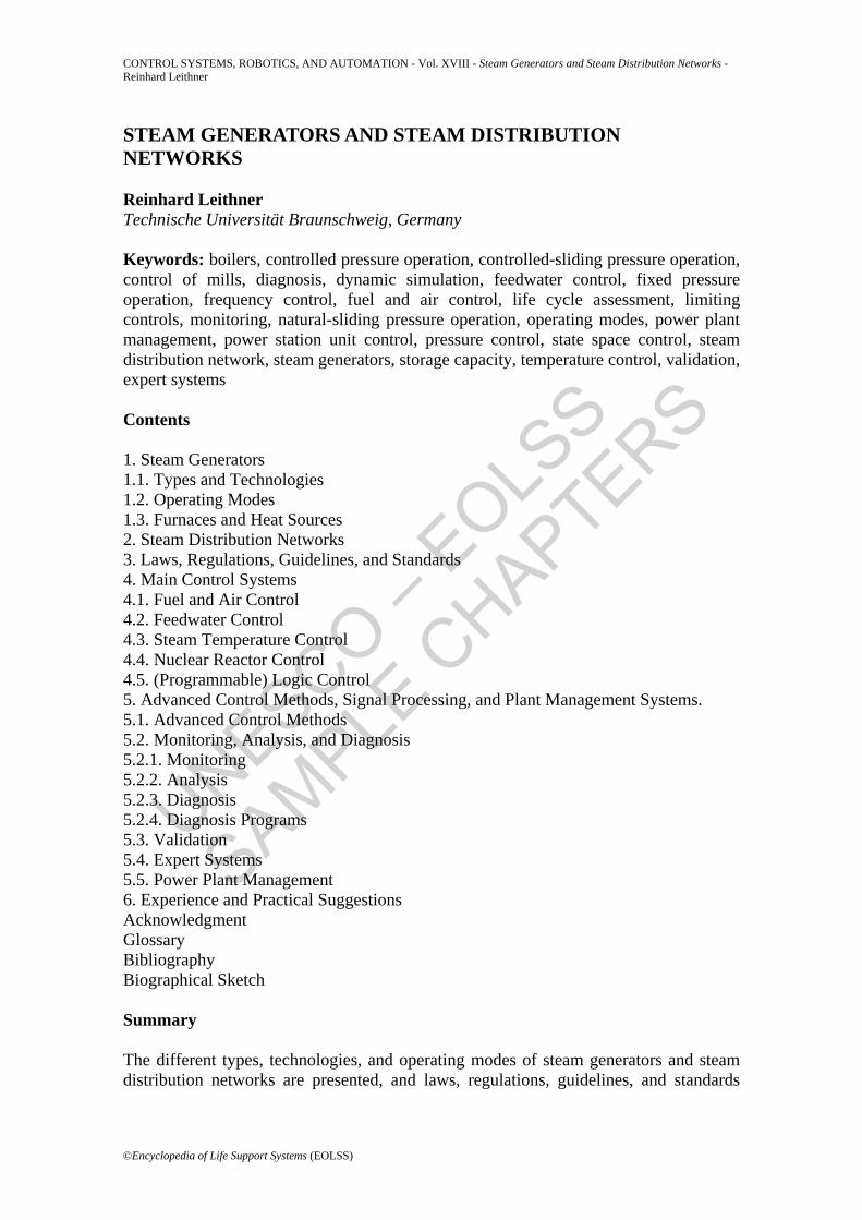
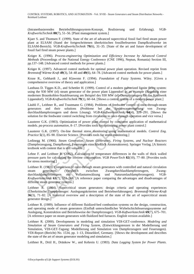
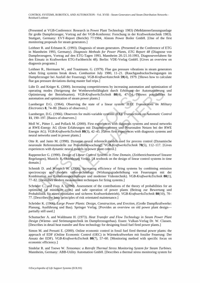
Figure 1 shows a shell-boiler, which is used for small industries such as slaughterhouses, breweries, paper mills, and laundries to produce not only saturated but also superheated steam. A shell-boiler is also used for heating larger buildings like hospitals, schools, and so on to produce hot water. This very simple (low cost) steam generator only needs simple controls: for example, an on/off control for the feedwater-pump if the water level is either too low or too high, and an on/off control for the firing system if the pressure is either too low or too high. How these simple controls work is shown in Figure 2. Of course with this simple control it is not useful to superheat the steam because there can be a steam flow without firing, and thus no heat is available for superheating. Such steam generators, using oil or gas as fuel, can also easily be operated by remote control without any operator on site for several days (if regulations permit) and they can also be monitored via the Internet.
Figure 1. Shell boiler design (economic boiler) (Source: Alstom Power Boiler GmbH, Stuttgart)
UNESCO – EOLS
S
SAMPLE C
HAPTERS
CONTROL SYSTEMS, ROBOTICS, AND AUTOMATION - Vol. XVIII - Steam Generators and Steam Distribution Networks - Reinhard Leithner
©Encyclopedia of Life Support Systems (EOLSS)
Figure 2. Pressure control by simple switching on/off firing system (fuel and air flow). (Similar control of water level by switching on/off feedwater-pump.) (Source: Dŏlecal,
1985)
The reason for the ease of control is the high storage capacity resulting from the high amount of saturated water stored in the vessel representing also a high amount of energy and potential of destruction in the case of the vessel bursting. The steam storage capacity can easily be calculated according to the following formula (ignoring steam produced by the heat released from the steel of the tubes and drum and so on, according to the changing saturation temperature):
ττ ddpc
ddp
dpdh
rmmSt ⋅−=⋅⋅−=Δ
''. (1)
Relating the steam flow change to the steam flow at maximum continuous rate (m.c.r.) and the pressure at m.c.r. (using pΔ instead of dp/dτ) one gets:
00
0
0p
p.
m
mdpdh
rp
m
.m
.'
.St Δ
⋅′
⋅⋅−=Δ
(2)
in which the formula
UNESCO – EOLS
S
SAMPLE C
HAPTERS
CONTROL SYSTEMS, ROBOTICS, AND AUTOMATION - Vol. XVIII - Steam Generators and Steam Distribution Networks - Reinhard Leithner
©Encyclopedia of Life Support Systems (EOLSS)
1
0
Tm
m.
'= (3)
is the time required to fill the evaporator-vessel with a water flow equivalent to the steam flow at m.c.r., which should be at least the capacity of the feedwater-pump. Knowing that in the usual pressure range for such steam generators of 5 to 20 bar
1100 ,dpdh
rp '
≈⋅ (4)
and using
21110 TT, =⋅ (5)
the dimensionless storage capacity becomes
02
0p
pTm
.m
.
.St Δ
−=Δ
(6)
The start-up time Ts of such a steam generator (neglecting again the heat stored in the steel and only taking into account the heat stored in the saturated water) using the m.c.r. firing heat rate 0
.Q as
)hh(mQ w''
..−= 00 (7)
becomes
)hh()hh(T
)hh(m
)hh(m
Q
)hh(mTw
''w
'
w''
.w
''
.w
''
s−−
=−
−=
−= 1
00 (8)
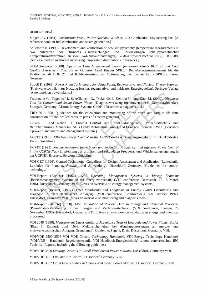
and is of course connected to the storage capacity, that is, a high storage capacity means a long start-up time. Figure 3 shows the flow diagrams of the five steam generator systems generally in use worldwide for larger industrial (>50 t h–1) and power station water-tube steam generators with all possible fuels.

UNESCO – EOLS
S
SAMPLE C
HAPTERS
CONTROL SYSTEMS, ROBOTICS, AND AUTOMATION - Vol. XVIII - Steam Generators and Steam Distribution Networks - Reinhard Leithner
©Encyclopedia of Life Support Systems (EOLSS)
Figure 3. Flow diagrams of water-tube steam generator systems for industrial and power plant steam generators
Figure 4. Simplified scheme of the arrangement of the heating surfaces of a water-tube steam generator
UNESCO – EOLS
S
SAMPLE C
HAPTERS
CONTROL SYSTEMS, ROBOTICS, AND AUTOMATION - Vol. XVIII - Steam Generators and Steam Distribution Networks - Reinhard Leithner
©Encyclopedia of Life Support Systems (EOLSS)
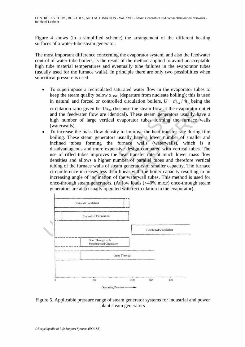
Figure 4 shows (in a simplified scheme) the arrangement of the different heating surfaces of a water-tube steam generator. The most important difference concerning the evaporator system, and also the feedwater control of water-tube boilers, is the result of the method applied to avoid unacceptable high tube material temperatures and eventually tube failures in the evaporator tubes (usually used for the furnace walls). In principle there are only two possibilities when subcritical pressure is used:
• To superimpose a recirculated saturated water flow in the evaporator tubes to keep the steam quality below xDNB (departure from nucleate boiling); this is used in natural and forced or controlled circulation boilers, fwevt mmU /= being the circulation ratio given be 1/xeo (because the steam flow at the evaporator outlet and the feedwater flow are identical). These steam generators usually have a high number of large vertical evaporator tubes forming the furnace walls (waterwalls).
• To increase the mass flow density to improve the heat transfer rate during film boiling. These steam generators usually have a lower number of smaller and inclined tubes forming the furnace walls (waterwalls), which is a disadvantageous and more expensive design compared with vertical tubes. The use of rifled tubes improves the heat transfer rate at much lower mass flow densities and allows a higher number of parallel tubes and therefore vertical tubing of the furnace walls of steam generators of smaller capacity. The furnace circumference increases less than linear with the boiler capacity resulting in an increasing angle of inclination of the waterwall tubes. This method is used for once-through steam generators. (At low loads (<40% m.c.r) once-through steam generators are also usually operated with recirculation in the evaporator).
Figure 5. Applicable pressure range of steam generator systems for industrial and power plant steam generators
UNESCO – EOLS
S
SAMPLE C
HAPTERS
CONTROL SYSTEMS, ROBOTICS, AND AUTOMATION - Vol. XVIII - Steam Generators and Steam Distribution Networks - Reinhard Leithner
©Encyclopedia of Life Support Systems (EOLSS)
The pressure range applicable for these steam generator types is given in Figure 5 These two methods also result in completely different behavior of the boilers and feedwater and superheater temperature control (see Sections 4.2 and 4.3). If supercritical pressure is used, the design can be either a once-through steam generator with a smaller number of parallel waterwall (furnace wall) tubes, which are inclined and have a smaller diameter, or a combined circulation steam generator with a higher number of parallel waterwall tubes, which are vertical and have a bigger diameter; these arrangements provide the high necessary mass flow density by a small flow area or a recycled mass flow respectively. During start-up in the once-through steam generators a separator and a circulating pump are usually used, whereas in the combined circulation steam generator throttle valves beyond the waterwalls provide for supercritical pressure in the waterwalls (and subcritical pressure at the live steam outlet) during start-up. This allows use of a T-piece instead of a separator to branch off the recirculation flow. The feedwater control of a combined circulation steam generator is similar to the feedwater control of a once-through steam generator. Usually the circulation (pump) of a combined circulation steam generator is not controlled. Less important (or nearly negligible) for the control systems are the shape and size (above a certain limit) of the steam generator. Small steam generators usually have simpler control systems. - - -
TO ACCESS ALL THE 54 PAGES OF THIS CHAPTER,
Click here
Bibliography
Adamietz M., Linnemann C., and Schröder J.J. (1999). Online monitoring of process quality of an 880MW bituminous coal fired power plant (On-line-Prozeßgüteüberwachung eines 880-MW-Steinkohlekrafterks). VGB-KraftwerksTechnik 79(8), 41–47. [Describes a modern monitoring system.]
ASME-Codes, e.g. ASME-Power-Test-Code
Aumüller A., Bobik M., and Cox, W. (1996). On-line-measurement of corrosion of evaporator tubes during low NOX operation of a bituminous coal fired furnace using international coals (On-line-Korrosionsmessung an Verdampferrohren während luftseitiger Primärmaßnahmenfahrweise zur NOx-Reduktion bei einer steinkohlebefeuerten Großanlage unter Berücksichtigung des Einsatzes von Importkohlen). VGB-Kraftwerkstechnik 76(9), 762–765. [Describes a measurement method to indicate evaporator tube corrosion by flue gas.]
Bozic O., Müller H., and Leithner R. (2000). Calculation of the Mineral Matter Transformations in Coal Fired Furnaces to Simulate Slagging. (Proceedings of 12th International Conference on Coal Research Sandton, South Africa, November, 2000), pp. 163–169. [Shows slagging models and simulations.]
Brockmeier U. (1999). Validation of process data in a power plant (Validierung von Prozeßdaten in
UNESCO – EOLS
S
SAMPLE C
HAPTERS
CONTROL SYSTEMS, ROBOTICS, AND AUTOMATION - Vol. XVIII - Steam Generators and Steam Distribution Networks - Reinhard Leithner
©Encyclopedia of Life Support Systems (EOLSS)
Kraftwerken). VGB-KraftwerksTechnik 79(9), 61–66. [Explains the data validation in power plants.]
Buchmayr B., Cerjak H., Wakonig H., Kleemaier R., and Nowotny, P. (1990). Expert system for the analysis of steam generator damage (Expertensystem zur Analyse von Schäden an Dampferzeugern). VGB-Kraftwerkstechnik 70(9), 749–753. [Expert system for analyzing steam generator damage.]
Bunk M., and Hornisch H.-J. (1999). Integrated machine diagnosis (Die integrierte Maschinendiagnose). VGB-KraftwerksTechnik 79(2), 44–46. [Shows state of the art machine diagnosis systems.]
Cichocki A. and Unbehauen R.. (1993). Neural Networks for Optimization and Signal Processing. Wiley. [A textbook on neural networks.]
DIN 1942: Steam Generator Acceptance Tests (Abnahmeversuche an Dampferzeugern). [Standard.]
DVG-Booklet (Broschüre) (1991). Supply Conform Operation of Thermal Power Plants, (Das versorgungsgerechte Verhalten der thermischen Kraftwerke). Deutsche Verbundgesellschaft e.V. (Heidelberg). [Guidelines.]
Farwick H. (1997). Combination of monitoring, diagnosis, and management Systems (Verbindung von Monitoring-, Diagnose- und Betriebsführungssystemen). VDI-Report (Bericht) 1359, pp. 3–34. Düsseldorf, Germany. [Shows the combination of monitoring, diagnosis, and management systems.]
FDBR 2000. European regulation for steam generators (Europäische Normen für Dampfkessel). Brennstoff-Wärme-Kraft 52(12), 3. [Gives an overview on new European Regulations]
Föllinger O. (1994). Control Systems, (Regelungstechnik). Heidelberg: Hüthig Buch Verlag. [A textbook on control systems.]
Fryling G.R. (1966). Combustion-Engineering. New York: Combustion Engineering Inc. [A reference book on fuel combustion and steam generation.]
Gierend C. and Born M. (2001). Process command by multivariable control of characteristic diagrams shown by thermal waste treatment. VGB-PowerTech 81(7), 47–51. [Advanced control system for optimized start up of steam power plants.]
Griem H., Köhler W., and Schmidt H. (1999). Heat transfer, pressure drop, and stress in evaporator waterwalls (Wärmeübergang, Druckverlust und Spannungen in Verdampferrohrwänden). VGB-KraftwerksTechnik 79(1), 30–39. [Furnace water wall design.]
Hormel M. (1995). Increasing efficiency of steam turbine plants by optimizing load distribution (Effizienzsteigerung von Dampfturbinenanlage durch optimale Lastverteilung). VDI-Report (Bericht) No. 1184: Neural Networks (Neuronale Netze): Applications in Automation Technologies (Anwendungen in der Automatisierungstechnik), Düsseldorf, Germany. [Applications of neural networks.]
Jensen, K. (1995, 1996, 1997) Colored Petri-Nets. Vols. 1–3. Heidelberg: Springer Verlag. [A textbook on Petri-Nets.]
Jovanovic A. and Maile K. (1996). ESR-VGB-An intelligent software tool for analyzing the residual lifetime of pipes (ESR-VGB-Ein intelligentes Softwarepaket zur Restlebensdaueranalyse von Rohrleitungen). VGB-Kraftwerkstechnik 76(12), 995–998. [An expert system for life time analysis of pipes in steam power plants.]
Kakac S. (1991). Boiler, Evaporators, and Condensers. Wiley. [This book is a collection of various contributions on heat exchangers and thermal power plants (fossil-fuel fired and nuclear reactors).]
Kallina G. (1995). Foresighted load change calculator for optimizing start-ups of steam generators (Voraussschauender Freilastrechner für das optimale Anfahren von Dampferzeugern). VGB-Kraftwerkstechnik 75(7), 578–582. [Advanced control system for optimized start up of steam power plants.]
Kallina G., Näser W., and Welfonder E. (1996). Improved load control concept for steam power plants (Verbessertes Leistungsregelkonzept für Dampfkraftwerke). VDI-Report (Bericht) 1245: Control- and Optimization-System for the Coordinated Power Plant and Electrical Net Operation, (Regelungs- und Optimierugskonzepte für den koordinierten Kraftwerks- und Netzbetrieb). Düsseldorf, Germany. [Advanced load control system for steam power plants.]
Kinn T. and Sasko P. (2000). Intranet based plant management system-design, realization and experience
UNESCO – EOLS
S
SAMPLE C
HAPTERS
CONTROL SYSTEMS, ROBOTICS, AND AUTOMATION - Vol. XVIII - Steam Generators and Steam Distribution Networks - Reinhard Leithner
©Encyclopedia of Life Support Systems (EOLSS)
(Intranetbasierendes Betriebsführungssystem-Konzept, Realisierung und Erfahrung). VGB-KraftwerksTechnik 80(7), 51–56. [Plant management system.]
Kjaer S. and Thomsen F. (1999). State of the art of advanced supercritical fossil fuel fired steam power plant at ELSAM (Stand der fortgeschrittenen überkritischen fossilbefeuerten Dampfkraftwerke im ELSAM-Bereich). VGB-KraftwerksTechnik 79(6), 31–35. [State of the art and future development of fossil fuel fired steam power plants.]
Krüger K. (1996). Process-engineering Optimization and Efficiency Increase by Advanced Control Methods (Proceedings of the National Energy Conference (CNE 1996), Neptun, Romania) Section III, pp.137–148. [Advanced control methods for power plants.]
Krüger K. (1997). Advanced control methods for optimal power plant operation. Revised reprint from Brennstoff Wärme Kraft 49(3), 54–48 and 49(6), 64–78. [Advanced control methods for power plants.]
Kruse R., Gebhardt J., and Klawonn F. (1994). Foundation of Fuzzy Systems. Wiley. [Gives a comprehensive overview of theory and application.]
Lasthaus D. Tigges K.D., and Schettler H. (1999). Control of a modern pulverized lignite firing system: using the 930 MW (el) steam generator of the power plant Lippendorf as an example (Regelung einer modernen Braunkohlen-Staubfeuerung am Beispiel des 930 MW (el)-Dampferzeugers für das Kraftwerk Lippendorf). VGB-KraftwerksTechnik 79(1), 60–64. [Shows a control system of a modern power plant.]
Läubli F., Leithner R., and Trautmann G. (1984). Problems of feedwater control of once-through-steam generators and their solutions (Probleme bei der Speisewasserregelung von Zwang-durchlaufdampferzeugern und deren Lösung). VGB-Kraftwerkstechnik 64(4), 279–291. [Shows the solution for the feedwater control switching from circulation to once-through operation and vice versa.]
Lausterer G.K. (1983). Optimization of power plant control by consistent application of mathematical models. pa-process automation, 8–17. [Provides tools for optimizing power plant control.]
Lausterer G.K. (1997). On-line thermal stress monitoring using mathematical models. Control Eng. Practice 5(1), 85–90. Elsevier Science. [Provides tools for stress monitoring.]
Ledinegg M. (1966). Steam Generation, Steam Generators, Firing Systems, and Nuclear Reactors (Dampferzeugung, Dampfkessel, Feuerungen einschließlich Atomreaktoren). Springer Verlag. [A historic textbook with content that is still valuable.]
Lehne F. and Leithner R. (2002). Calculation of temperature differences in the walls of thick walled pressure parts for calculating the lifetime consumption. VGB PowerTech 82(10), 77–80. [Provides tools for stress monitoring.]
Leithner R. (1983). Comparison of once-through steam generators with controlled and natural circulation steam generators. (Vergleich zwischen Zwangdurchlaufdampferzeugern, Zwang- durchlaufdampferzeugern mit Vollastumwälzung und Naturumlaufdampferzeugern). VGB-Kraftwerkstechnik 63(7), 553–568. [A reference paper comparing the advantages and disadvantages of different steam generator systems.]
Leithner R. (1984). Supercritical steam generators: design criteria and operating experiences (Überkritische Dampferzeuger: Auslegungskriterien und Betriebserfahrungen). Brennstoff-Wärme-Kraft 36(3), 71–82. [A historical overview and a description of the state of the art of supercritical steam generator design.]
Leithner R. (1989). Influence of different fluidized-bed combustion systems on the design, construction, and operating mode of steam generators (Einfluß unterschiedlicher Wirbelschichtfeuerungssysteme auf Auslegung, Konstruktion und Betriebsweise der Dampferzeuger). VGB-Kaftwerkstechnik 69(7), 675–701. [A reference paper on steam generators with fluidized bed furnaces. English version available.]
Leithner R. (2000). Developments in modeling and simulation VDI-GET-conference. Modeling and Simulation of Steam Generators and Firing System, (Entwicklungstenzen in der Modellierung und Simulation, VDI-GET-Tagung: Modellierung und Simulation von Dampferzeugern und Feuerungen). VDI-Report (Bericht) No. 1534, pp. 1–13, Düsseldorf, Germany. [Shows the development and describes the state of the art of steam generator modeling and simulation.]
Leithner R., Drtil H., Dränkow W., and Kehrein U. (1983). Data Logging System for Power Plants.
UNESCO – EOLS
S
SAMPLE C
HAPTERS
CONTROL SYSTEMS, ROBOTICS, AND AUTOMATION - Vol. XVIII - Steam Generators and Steam Distribution Networks - Reinhard Leithner
©Encyclopedia of Life Support Systems (EOLSS)
(Presented at VGB-Conference: Research in Power Plant Technology 1983) (Meßdatenerfassungsanlage für große Dampferzeuger, Vortrag auf der VGB-Konferenz: Forschung in der Kraftwerkstechnik 1983). Stuttgart, Germany: EVT-Report (Bericht) 77/1984, Alstom Power Boiler GmbH. [One of the first monitoring proposals for steam generators.]
Leithner R. and Erlmann K. (1993). Diagnosis of steam generators. (Presented at the Conference of ETG in Mannheim 1993, Germany). Diagnosis Methods for Power Plants, ETG Report 48 (Diagnose von Dampferzeugern, Vortrag auf den ETG-Tagen 1993, Mannheim 20./21.10.1993, Diagnoseverfahren für den Einsatz in Kraftwerken ETG-Fachbericht 48). Berlin: VDE-Verlag GmbH. [Gives an overview on diagnosis programs.]
Leithner R., Herrmann W., and Trautmann. G. (1979). Flue gas pressure vibrations in steam generators when firing systems break down. Combustion July 1980, 11–21. (Rauchgasdruckschwingungen im Dampferzeuger bei Ausfall der Feuerung). VGB-Kraftwerkstechnik 59(4), 1979. [Shows how to calculate flue gas pressure deviations during master fuel trips.]
Lühr D. and Krüger K. (2000). Increasing competitiveness by increasing automation and optimization of operating modes (Steigerung der Wettbewerbsfähigkeit durch Erhöhung der Automatisierung und Optimierung der Betriebsarten). VGB-KraftwerksTechnik 80(4), 47–54. [Shows possibilities for automation and optimization of steam power plants.]
Luenberger D.G. (1964). Observing the state of a linear system. IEEE Transactions on Military Electronics 8, 74–80. [Basics of observers.]
Luenberger, D.G. (1966). Observers for multi-variable systems. IEEE Transactions on Automatic Control 11, 190–197. [Basics of observers.]
Moll W., Pütter J., and Pollack M. (2000). First experiences with diagnosis systems and neural networks at RWE-Energy AG (Erste Erfahrungen mit Diagnosesystemen und Neuronalen Netzen bei der RWE Energie AG). VGB-KraftwerksTechnik 80(3), 42–45. [Gives first experiences with diagnosis systems and neural networks used in power plants.]
Otte R. and Janto M. (1998). Dynamic neural reference models used for process control (Dynamische neuronale Referenzmodelle zur Prozeßüberwachung). VGB-KraftwerksTechnik 78(5), 112–117. [Gives experiences with dynamic neural models in power plant control.]
Rappenecker G. (1990). Design of Linear Control Systems in Time Domain, (Zeitbereichsentwurf linearer Regelungen), Munich: R. Oldenbourg Verlag. [A textbook on the design of linear control systems in time domain.]
Schmidt D. and Wintrich H. (2000). Increasing efficiency of firing systems by combining emission spectroscopy and modern video-technology (Wirkungsgraderhöhung von Feuerungen mit der Kombination aus Emissionsspektroskopie und moderner Videotechnik). VGB-KraftwerksTechnik 80(1), 77–82. [Describes modern measurement techniques for firing systems.]
Schröder C., and Foos A. (2000). Assessment of the contributions of the theory of probabilities for an optimized (at minimum costs) and safe operation of power plants (Beitrag zur Bewertung und Probabilistik für einen optimalen und sicheren Kraftwerksbetrieb). VGB-KraftwerksTechnik 80(10), 70–77. [Describes the basic principles of risk orientated maintenance.]
Schröder K. (1966). Large Power Plants: Design, Construction, and Erection, (Große Dampfkraftwerke: Planung, Ausführung und Bau). Springer Verlag. [Provides an overview on old power plant design––partially still used.]
Schumacher A. and Waldmann H. (1973). Heat Transfer and Flow Technology in Steam Power Plant Design (Wärme- und Strömungstechnik im Dampferzeugerbau). Essen: Vulkan-Verlag Dr. W. Classen. [Describes in detail heat transfer and flow technology for designing fossil fuel fired power plants.]
Simon M. and Presutti E. (2000). Online economic control in fossil fuel fired thermal power plants: the approach of EDF (Online Economic Control (OEC) in Wärmekraftwerken mit fossiler Feuerung: Der Ansatz der EDF). VGB-KraftwerksTechnik 80(7), 57–60. [Monitoring method with specific focus on economic efficiency.]
Sindelar R. and Toewe W. Tensomax: a Retrofit Thermal Stress Monitoring System for Steam Turbines. Mannheim, Germany: ABB-Utility Automation GmbH. [Describes a thermal stress monitoring system for
UNESCO – EOLS
S
SAMPLE C
HAPTERS
CONTROL SYSTEMS, ROBOTICS, AND AUTOMATION - Vol. XVIII - Steam Generators and Steam Distribution Networks - Reinhard Leithner
©Encyclopedia of Life Support Systems (EOLSS)
steam turbines.]
Singer J.G. (1981). Combustion-Fossil Power Systems. Windsor, CT: Combustion Engineering Inc. [A reference book on fuel combustion and steam generation.]
Spliethoff H. (1996). Development and verification of acoustic pyrometry (temperature measurement) in two pulverized coal furnaces (Untersuchungen und Entwicklungen schallpyrometrischer Temperaturmeßverfahren an zwei Kohlenstaubfeuerungen). VGB-Kraftwerkstechnik 76(7), 581–588. [Shows a modern method of measuring temperature distributions in furnaces.]
STEAG-encotec (2000). Operation Data Management System for Power Plants BDE 21 and Coal Quality Assessment Program to Optimize Coal Buying SPICE (Betriebsdatenmanagement für die Kraftwirtschaft BDE 21 und Kohlebewertung zur Optimierung des Kohleeinkaufs SPICE). Essen, Germany.
Strauß K. (1992). Power Plant Technology: for Using Fossil, Regenerative, and Nuclear Energy Sources, (Kraftwerkstechnik – zur Nutzung fossiler, regenerativer und nuklearer Energiequellen). Springer-Verlag. [A textbook on power plants.]
Trautmann G., Tegethoff J., Scheffknecht G., Tsolakidis I., Kehrein U., and Daur M. (2000). Diagnosis Tool for Conventional Steam Power Plants, (Diagnosewerkzeug für konventionelle Dampfkraftwerke). Stuttgart, Germany: Alstom Energy Systems GmbH. [Describes a diagnosis tool.]
TRD 301+ 508, [guidelines for the calculation and monitoring of the creep and fatigue life time consumption of thick walled pressure parts of a steam generator]
Tütken T. and Röben U. Process Control and Plant Management (Prozeßleittechnik und Betriebsführung). Mannheim: ABB Utility Automation GmbH, and Erlangen: Siemens KWU. [Describes a power plant control and management system.]
UCPTE (1990). Effective Power Control in the UCPTE-Net (Wirkleistungsregelung im UCPTE-Netz). Paris. [Guideline]
UCPTE (1995). Recommendations for Primary and Secondary Frequency: and Effective Power Control in the UCPTE-Net, (Empfehlung zur primären und sekundären Frequenz: und Wirkleistungsregelung in der UCPTE). Brussels, Belgium. [Guideline.] VDI-GET (1996). Control Technology: Guidelines for Design, Assessment and Application (Leittechnik: Leitfaden für Planung, Auswahl und Anwendung). Düsseldorf, Germany. [Guidelines for control technology.]
VDI-Report (Bericht) (1966). 1252 Operating Management Systems in Energy Economy (Betriebsmanagement-Systeme in der Energiewirtschaft) (VDI conference, Darmstadt, 12–13 March 1996). Düsseldorf, Germany: VDI. [Gives an overview on energy management systems.]
VDI-Report (Bericht) (1977). 1359 Monitoring and Diagnosis in Energy Plants (Monitoring und Diagnose in energietechnischen Anlagen). (VDI conference, Braunschweig 8–9 October 1997). Düsseldorf, Germany: VDI. [Gives an overview on monitoring and diagnosis tools.]
VDI-Report (Bericht) (1998). 1451 Validation of Process Data in Energy and Chemical Processes (Prozeßdaten-Validierung in der Energie- und Verfahrenstechnik). (VDI conference, Langen, 25 November 1998). Düsseldorf, Germany: VDI. [Gives an overview on validation in energy and chemical processes.]
VDI 2048 (1998). Measurement Uncertainties of Acceptance Tests of Energetic and Power Plants: Basics (Blatt 1, Entwurf, Juni 1998, Meßunsicherheiten bei Abnahmemessungen an energie- und kraftwerkstechnischen Anlagen. Grundlagen). Guideline, Page 1, Draft. Düsseldorf, Germany: VDI.
VDI/VDE 3500–3508 VDI–VDE Control Technology Handbook, VDI Energy Technology Handbook (VDI/VDE – Handbuch Regelungstechnik, VDI-Handbuch-Energietechnik) is now converted into IEC Technical Reports, including the following guidelines:
VDI/VDE 3500 Limiting Controls in Fossil Fired Steam Power Stations. Düsseldorf, Germany: VDI.
VDI/VDE 3501 Fuel and Air Control. Düsseldorf, Germany: VDI.
VDI/VDE 3502 Drum Level Control in Fossil Fired Steam Power Stations. Düsseldorf, Germany: VDI.

UNESCO – EOLS
S
SAMPLE C
HAPTERS
CONTROL SYSTEMS, ROBOTICS, AND AUTOMATION - Vol. XVIII - Steam Generators and Steam Distribution Networks - Reinhard Leithner
©Encyclopedia of Life Support Systems (EOLSS)
VDI/VDE 3503 Steam Temperature Control in Fossil Fired Steam Power Stations. Düsseldorf, Germany: VDI.
VDI/VDE 3504 Furnace Pressure Control. Düsseldorf, Germany: VDI.
VDI/VDE 3505 Primary Air Flow and Classifier Temperature Control for Coal Mills. Düsseldorf, Germany: VDI.
VDI/VDE 3506 Feedwater Control for Once-Through Boilers in Fossil Fired Steam Power Stations. Düsseldorf, Germany: VDI.
VDI/VDE 3508 Thermal Power Plant Control. Düsseldorf, Germany: VDI. Düsseldorf, Germany: VDI.
Vollmüller M., Axmann J.K., and Dobrowolski R. (2001). Optimized short term power plant operation scheduling under consideration of load forecast errors (Kurzfristige Kraftwerkseinsatzoptimierung unter Berücksichtigung von Lastprognosefehlern). VGB-PowerTech 81(9), 36–39. [Describes an optimization tool for managing a pool of power plants.]
Wendelberger K., Meerbeck B., and Hüngerl M. (2002). Automation systems for improving economy of power plants (Automatisierungskonzepte für wirtschaftlichere Kraftwerke). Brennstoff-Wärme-Kraft 54(10), 50–52. [Describes automation systems for improving economic efficiency of power plants.] Biographical Sketch Prof. Dr. techn. R. Leithner was born in 1945 in Schärding, Austria. He graduated as Dipl.-Ing. (Mechanical Engineering) from the Technical University in Vienna in 1970 with a thesis on measurement and simulation of a heat exchanger. From 1971 till 1983 he worked in different positions with Energie- und Verfahrenstechnik GmbH (now Alstom Power Boiler GmbH), Stuttgart, one of the leading steam generator manufacturers in Germany. During his period at EVT he wrote a doctoral thesis on the mass flow from an equally heated tube at constant pressure and graduated as Dr. techn. from the Technical University in Vienna in 1976.
His last position in this company was head of the “main department for steam generator design, development and commissioning”, where his responsibilities included stress analyses and control systems; also the power of a procurator was granted him. In 1983 he was appointed professor and director of the IWBT-TU BS. In all these positions he has always been involved in power plant design, calculation, control, and simulation.