Deposit formation in PWR steam generators
33
RESEARCH REPORT VTT-R-00135-10 Deposit formation in PWR steam generators Authors: Mikko Vepsäläinen Confidentiality: Public
Transcript of Deposit formation in PWR steam generators
RESEARCH REPORT VTT-R-00135-10
Deposit formation in PWR steamgeneratorsAuthors: Mikko Vepsäläinen
Confidentiality: Public

RESEARCH REPORT VTT-R-00135-10
1 (32)
Report’s titleDeposit formation in PWR steam generatorsCustomer, contact person, address Order referenceSAFIR2010, Finnish national research program on NPP safety2007-2010
VTT-R-00135-10
Project name Project number/Short nameMonitoring of the Structural Integrity of Reactor Circuit 32876 / RAKEMONAuthor(s) PagesMikko Vepsäläinen 32/Keywords Report identification codeSteam generator, deposit, fouling, nuclear energy VTT-R-00135-10SummaryFouling in the steam generators of pressurized water reactors can cause significantinconvenience at the nuclear power plants. Accumulation of deposits can lead to corrosionproblems, reduce heat transfer and cause tube plugging and flow problems. Secondary-sidewater chemistry has developed from phosphate-based treatment to all-volatile water treatment,which is based on the use of ammonia and hydrazine. Over the past 10 years, nuclear plantshave also used advanced amines to reduce corrosion and deposit precursor formation.
Deposits are formed mainly from corrosion products that are transported from the secondary-cycle. Iron oxides are the primary component in the deposits but they may contain significantproportions of copper and copper oxides depending on the construction materials of thesecondary-cycle. Soluble species, such as silicates and sulphates, can concentrate andprecipitate within deposits.
Flow-accelerated corrosion (FAC) on the secondary-cycle is the main source of the irondeposit precursors. On the FAC magnetite layer becomes thin due to enhanced dissolving atthe high flow and turbulence. FAC occurs at alkalinized and deaerated water. Temperature andpH have significant effect on the FAC, but may be difficult to change in operating plant.Using advanced amines can alleviate FAC, but some amines can be fouling enhancers.
The formation of deposits and sludge in the steam generator involve a range of possiblephysical and chemical phenomena such as turbulent deposition, boiling deposition,gravitational settling and re-entrainment. The deposition process is complex phenomena wheremultiple factors affect to deposit formation rate. Formed deposits and sludge can be removedfrom the steam generator by chemical and mechanical means.
Confidentiality PublicEspoo 4.2.2010Written by
Mikko Vepsäläinen,Research Scientist
Reviewed by
Ari KoskinenTeam Leader
Accepted by
Pentti KauppinenTechnology Manager
VTT’s contact addressMikko Vepsäläinen, P.O. Box 1000, FI-02044, FinlandDistribution (customer and VTT)SAFIR2010
The use of the name of the VTT Technical Research Centre of Finland (VTT) in advertising or publication in part ofthis report is only permissible with written authorisation from the VTT Technical Research Centre of Finland.
RESEARCH REPORT VTT-R-00135-10
2 (32)
Preface
This literature review has been made at VTT Espoo office during year 2009. This researchwas part of SAFIR2010, Finnish national research program on NPP safety 2007-2010.
Deposit formation in the nuclear power plant steam generators is significant problem thatcauses corrosion of materials, fluid restrictions and heat transfer reduction. There has beensignificant effort in the secondary-cycle chemistry area to reduce deposit formation and thereare numerous papers published in this field. This review gathers information that is related tocomposition of deposits, their formation and behaviour in the steam generators and techniquesthat are used to remove deposits from the surfaces. Objective of this review is to givebackground for further research work that is related to deposit monitoring and prevention.
Espoo 4.2.2010
Author

RESEARCH REPORT VTT-R-00135-10
3 (32)
Contents
Preface ........................................................................................................................2
1 Introduction.............................................................................................................4
2 Goal........................................................................................................................4
3 Composition of steam generator deposits and their precursors..............................53.1 Formation of deposit precursors in the secondary cycle .................................63.2 Steady-state generation of deposit precursors................................................8
3.2.1 Effect of temperature on flow accelerated corrosion ..........................103.2.2 Effect of water chemistry on flow accelerated corrosion ....................11
3.3 Transient generation of deposit precursors...................................................144 Deposit formation and behaviour in the steam generator .....................................14
4.1 Formation of tube scale.................................................................................174.2 Formation of sludge piles..............................................................................20
5 Copper in steam generator deposits.....................................................................215.1 Copper oxide formation and stability.............................................................235.2 Factors influencing copper corrosion and release activity.............................25
6 Removing deposits and sludge from the steam generators..................................286.1 Chemical cleaning of the steam generator....................................................286.2 Mechanical cleaning of the steam generator.................................................29
7 Conclusions..........................................................................................................30
8 Summary ..............................................................................................................30
References ................................................................................................................31
RESEARCH REPORT VTT-R-00135-10
4 (32)
1 Introduction
The generation and transport of corrosion products in the feedwater, drain andcondensate systems at a pressurized water reactor (PWR) plant results to theformation of deposits on the secondary side of steam generators (SG). Thesedeposits can increase the potential for corrosion of tube materials, cause fluid flowrestrictions that increase the pressure drop across the tube supports, reduce theheat transfer efficiency of the units, and prevent a utility from operating a plant atfull power [1, 2]. Heavy deposit formation in the steam generators is a pre-cursorfor material degradation. Deposits may also interfere with non-destructiveevaluation (NDE) of tubes by eddy current or ultrasonic techniques.
Nuclear power plants have changed secondary water treatment from phosphate toall-volatile treatment and "alternative" amines [3]. This has changed depositrelated problems from the sludge piles and tube phosphate wastage to deposits onthe tube surfaces and reductions on the heat transfer. In order to control depositformation and steam generator fouling, it is important to minimize the transport ofcorrosion products into the steam generator. That is the reason to try to controlcorrosion and corrosion product transport within the steam supply system. Butover time, even with careful system cycle water chemistry control, corrosionproducts will tend to accumulate in the steam generator. They eventually depositon surfaces, especially on the high-heat-flux surfaces and in the low-velocityregions. During operational thermal transients and hydraulic shock, deposits canbreak away from these surfaces and re-enter the fluid stream. During these “crudbursts”, particulate concentrations in the steam generator can climb dramatically.The deposition of dissolved and suspended species in a fluid is a very complexfunction of heat flux, species concentration, time, temperature, fluid velocity,surface chemistry and morphology, and pressure.
As mentioned, increased iron concentrations in the feedwater will result in highersteam generator fouling. Less obviously, increased concentrations of non-filterable dissolved iron may result in an increased fouling rate [2, 3]. Someamines used for pH control can enhance fouling, but on the other hand mitigateflow-accelerated corrosion (FAC) rate and lower corrosion product transport.
2 Goal
In this literature review, steam generator deposit formation is gone through indetail. Studies concerning the composition of deposits, the formation of depositprecursors during different stages of plant run and the mechanisms of depositformation are summarized. Understanding the role of copper in deposits isimportant, especially when copper compounds are used in the secondary cycle.Progress made on the steam generator deposit removal is summarised at the endof this report.
RESEARCH REPORT VTT-R-00135-10
5 (32)
3 Composition of steam generator deposits and theirprecursors
The processes, which govern the formation of deposits in PWR steam generatorsinvolve multiple steps, which begin with the generation of transportableprecursors in the secondary cycle. Once transported to steam generator precursorscan be (1) removed by blowdown, (2) transported by steam – “carry over”, (3)removed by chemical or mechanical means or (4) form permanent deposits in thesteam generator [1]. The deposit precursors are ionic, particulate and solublechemical species which are transported to steam generator mainly from elsewherein the plant. Probably much less than 10% of the deposits in a steam generator areformed in situ due the corrosion of carbon or alloy steel components of the steamgenerator. Most of the in situ deposits are actually desirable because theypassivate the steam generator surfaces and minimize further corrosion. Those in-situ deposits that form on tube support crevices and aggravate concentration ofcorrosive impurities or cause tube denting are harmful.
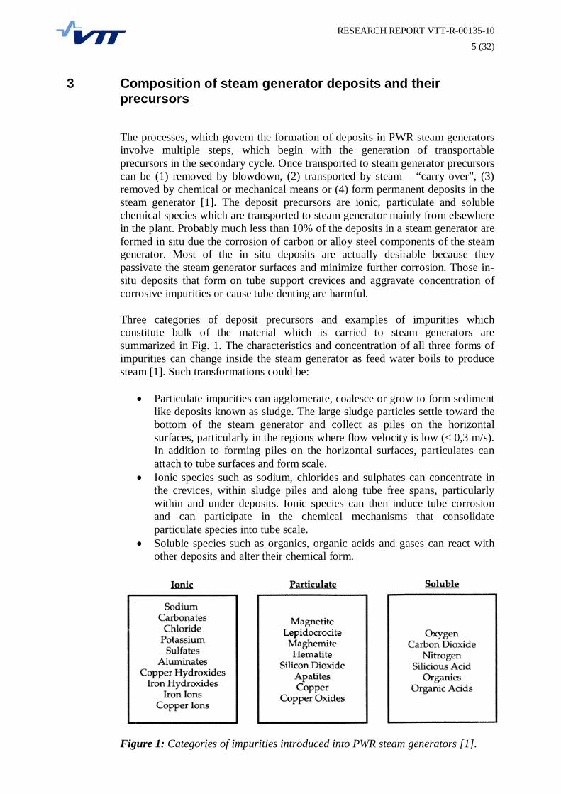
Three categories of deposit precursors and examples of impurities whichconstitute bulk of the material which is carried to steam generators aresummarized in Fig. 1. The characteristics and concentration of all three forms ofimpurities can change inside the steam generator as feed water boils to producesteam [1]. Such transformations could be:
Particulate impurities can agglomerate, coalesce or grow to form sedimentlike deposits known as sludge. The large sludge particles settle toward thebottom of the steam generator and collect as piles on the horizontalsurfaces, particularly in the regions where flow velocity is low (< 0,3 m/s).In addition to forming piles on the horizontal surfaces, particulates canattach to tube surfaces and form scale.Ionic species such as sodium, chlorides and sulphates can concentrate inthe crevices, within sludge piles and along tube free spans, particularlywithin and under deposits. Ionic species can then induce tube corrosionand can participate in the chemical mechanisms that consolidateparticulate species into tube scale.Soluble species such as organics, organic acids and gases can react withother deposits and alter their chemical form.
Figure 1: Categories of impurities introduced into PWR steam generators [1].

RESEARCH REPORT VTT-R-00135-10
6 (32)
3.1 Formation of deposit precursors in the secondary cycle
The potential sources of impurities which can be transported to the steamgenerator along the feedwater are presented in Fig. 2. Included in the Fig. 2 areplant components of a generic plant, which presents major features of operatingplants [1]. Precursor materials that are likely to be introduced during normaloperation are:
Ionic and soluble metallic species liberated by dissolution of corrosionfilms on piping and heat exchanger surfaces.Particulate species liberated by flow accelerated corrosion product filmson piping and components, particularly in wet steam piping downstream ofhigh pressure turbine.Gaseous, ionic, particulate and soluble materials introduces throughcondenser tube leaks.Corrosion products released from condenser tubing.Oils and greases used for equipment maintenance and repair.Organics not removed by the makeup water treatment.Oxygen, nitrogen and carbon dioxide contained in make-up water.Resin fines and beads from blowdown demineralizers, condensatepolishers or make-up water treatment systems.Chemicals used to regenerate resinsTrace impurities found in resin treatment chemicals.
Figure 2: Sources of steam generator deposit precursors [1].

RESEARCH REPORT VTT-R-00135-10
7 (32)
It can be seen that sources of impurities are many and varied and as a result thechemical composition of deposits varies greatly from plant to plant. To roughlyillustrate quantity of the precursors from different processes, Fig. 3 presents theflow of different types of species. The widths of the bars that connect the variouselements in this figure, are proportional to the mass transport of the depositprecursors [1].
Figure 3: Summary of corrosion product generation and transport [1].

RESEARCH REPORT VTT-R-00135-10
8 (32)
3.2 Steady-state generation of deposit precursors
The greatest source of the material impurities that find their way into steamgenerators are corrosion products liberated by flow accelerated corrosion (FAC)of carbon steel feedwater, drain and condensate system components [2, 4]. It hasbeen estimated that corrosion products account for approximately 90% of thedeposits in the steam generators [5]. This account for that steam generatordeposits consist primarily of iron oxides at nearly all PWR. At some plants coppercontaining alloys are used in condensers and heat exchangers which in turnprovide source for the copper and other alloy elements that are found in lesserquantities in the deposits.
The corrosion product films on carbon steel consist of magnetite, hematite,ferrous hydroxides and hydrated iron species. Flow accelerated corrosion (FAC)is a phenomenon that affects this normally protective oxide layer formed oncarbon or low-alloy steel. With FAC, the oxide layer dissolves into the flowingstream of water or a water-steam mixture. As the oxide layer becomes thinner andless protective, the corrosion rate increases. Eventually a steady state is reachedwhere corrosion and dissolution rates are equal. It is important to note that in theFAC process, the protective oxide film is not mechanically removed. Rather, theoxide is dissolved. Thus, FAC may be defined as corrosion enhanced by masstransfer between a dissolving oxide film and a flowing fluid that is unsaturated inthe dissolving species [2]. FAC affects carbon steel components in deaerated andalkalinized flowing water, mainly in the temperature range of 100°C to 300°C.Wall thinning rates are normally less than 0.03 mm/h (0.25 mm/year) but rates ashigh as approximately 0.34 mm/h (3 mm/year) have already been observed inoperating plants [6].
Because the protective layer reaches a near steady-state condition, where the rateof layer formation nearly equals the rate of layer dissolution, the FAC rate tendsto have a constant value. The FAC rate is proportional to velocity and turbulence.However, there is no known practical threshold velocity below which FAC willnot occur [7].
FAC occurs when the carbon or low alloy steel develops a porous magnetite layer.Soluble ferrous ions are produced at the oxide-water interface. Next, the ferrousions are transferred across the boundary layer. The concentration of ferrous ions inthe bulk water is very low compared to the concentration of ferrous ions at theoxide-solution interface. The FAC rate increases if there is an increase of waterflow past the oxide-water interface. One identifying characteristic of FAC ofcarbon and low-alloy steels is that the magnetite layer that is normally protectiveis dissolved by the flowing water stream [6]. Importantly, the removal of themagnetite occurs only by chemical dissolution. Flow is responsible fortransporting the dissolved iron away from the magnetite and into the bulk water.The FAC mechanism can be described as the action of four simultaneousreactions (Fig. 4) [8].

RESEARCH REPORT VTT-R-00135-10
9 (32)
Figure 4: Schematic picture of the flow accelerated corrosion mechanism [8].
1. Oxidation of iron to soluble ferrous ions and magnetite at the internal interfacebetween the steel and the oxide (Eq. 1 and 2).
H2OHFeO2HFe 2-2
2 (1)
2432 4HOFeO4H3Fe (2)
2. Diffusion of soluble species (iron and hydrogen) across the porous oxide anddiffusion of hydrogen through the carbon steel.
3. Dissolution and reduction of magnetite at the external interface between theoxide and the water (Eq. 3).
222
4243 NO8H6Fe12HHNO2Fe (3)
4. Transfer of soluble iron species towards the flowing water and transfer ofhydrogen towards the air after diffusion through the steel. The influence ofseveral parameters has been studied, such as water chemistry, temperature,hydrodynamic and mass transfer conditions as well as steel composition [6].As a matter of fact, most of these parameters are well described by models.Nevertheless, the effects of some parameters still require investigation to try tobetter understand the mechanism of the degradation and to help updateguidelines and improve FAC models. Hydrazine is used in plant units toguarantee a reducing environment in the secondary circuit as it is an oxygenscavenger (Eq. 4).
O2HNOHN 22242 (4)
RESEARCH REPORT VTT-R-00135-10
10 (32)
This mitigates secondary side stress corrosion cracking of steam generatortubes. Recent EDF/EPRI results [9] have shown that FAC could be increasedin such reducing environments under specific chemistry, temperature andhydraulic conditions.
3.2.1 Effect of temperature on flow accelerated corrosion
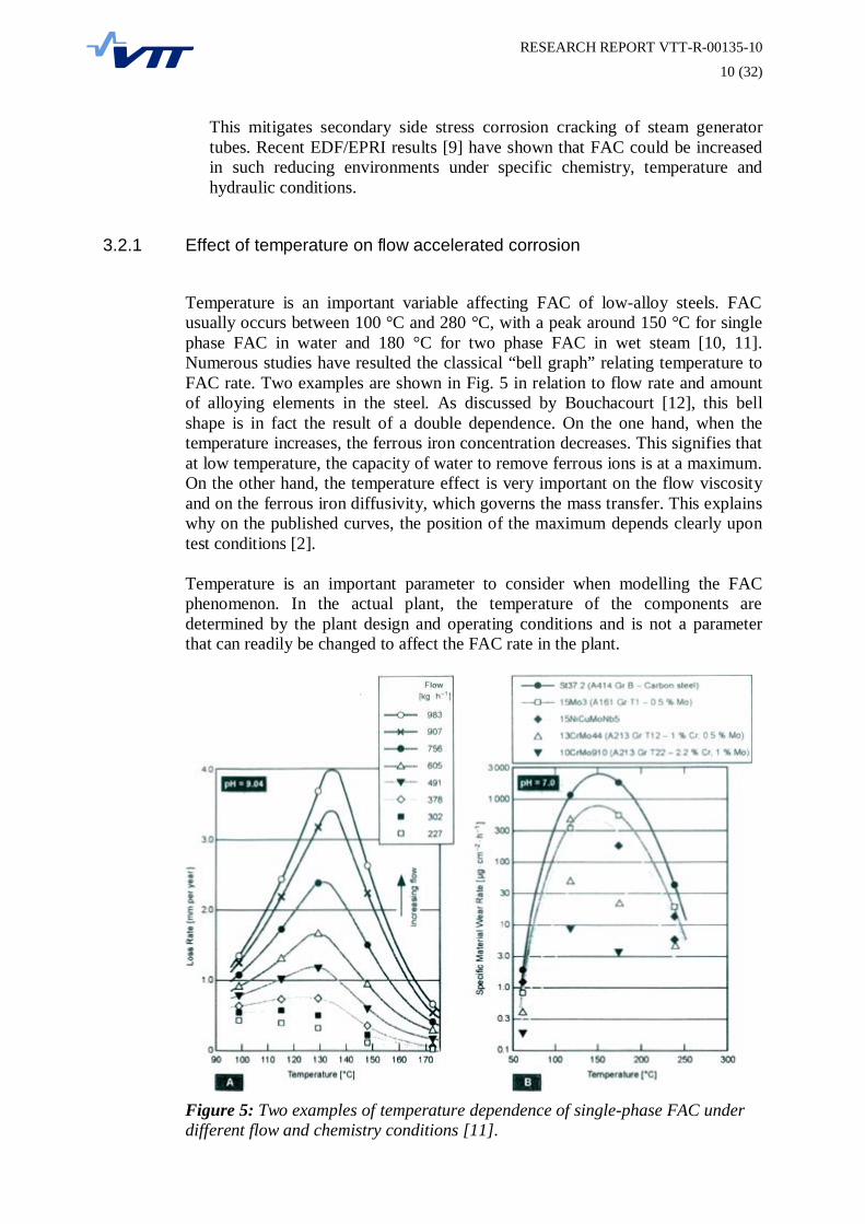
Temperature is an important variable affecting FAC of low-alloy steels. FACusually occurs between 100 °C and 280 °C, with a peak around 150 °C for singlephase FAC in water and 180 °C for two phase FAC in wet steam [10, 11].Numerous studies have resulted the classical “bell graph” relating temperature toFAC rate. Two examples are shown in Fig. 5 in relation to flow rate and amountof alloying elements in the steel. As discussed by Bouchacourt [12], this bellshape is in fact the result of a double dependence. On the one hand, when thetemperature increases, the ferrous iron concentration decreases. This signifies thatat low temperature, the capacity of water to remove ferrous ions is at a maximum.On the other hand, the temperature effect is very important on the flow viscosityand on the ferrous iron diffusivity, which governs the mass transfer. This explainswhy on the published curves, the position of the maximum depends clearly upontest conditions [2].
Temperature is an important parameter to consider when modelling the FACphenomenon. In the actual plant, the temperature of the components aredetermined by the plant design and operating conditions and is not a parameterthat can readily be changed to affect the FAC rate in the plant.
Figure 5: Two examples of temperature dependence of single-phase FAC underdifferent flow and chemistry conditions [11].

RESEARCH REPORT VTT-R-00135-10
11 (32)
3.2.2 Effect of water chemistry on flow accelerated corrosion
Feedwater pH and the distribution coefficient of the amine (or ammonia) used tocontrol pH are the key variables determining the rates of FAC and thereforecorrosion product transport. Some studies have shown that for all-ferroussecondary systems, the optimum pH for minimizing overall corrosion producttransport is in the range of 9.3 – 9.6. European field studies reveal that even pH9.8 and greater is required to minimize corrosion product generation in the feedwater. Plants, that have used all volatile treatment with the high pH of >9.8 (H-AVT) from the beginning, don't show significant decrease of the heat transferafter 15 years [13]. However, when copper is present in the secondary cyclecomponents, such high pHs will result in increased copper dissolution andtransport to steam generators. At plants with copper components, pH is usuallymaintained below 9.3 [1].
It is well established that the at-temperature pH (pHT) of the high-purity watersystem has a first-order effect on the FAC rate of carbon steels [6, 10, 12]. This isnot surprising, since the FAC rate is directly related to the solubility of iron,which in turn is related to the pH or more specifically the at-temperature pH of thewater stream. This is illustrated graphically in Fig. 6 for magnetite in water at250°C. A pH shift of 0,5 units from the minimum effectively doubles thecorrosion rate. The at-temperature pH is a function of the specific amine orcombination of amines and ammonia used for pH control [14].
Figure 6: Iron Solubility (Magnetite) at 250°C versus pHT [14].
RESEARCH REPORT VTT-R-00135-10
12 (32)
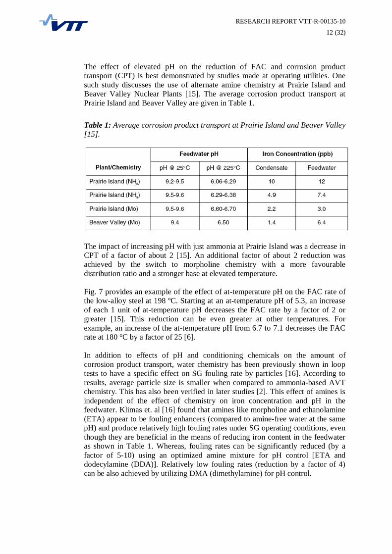
The effect of elevated pH on the reduction of FAC and corrosion producttransport (CPT) is best demonstrated by studies made at operating utilities. Onesuch study discusses the use of alternate amine chemistry at Prairie Island andBeaver Valley Nuclear Plants [15]. The average corrosion product transport atPrairie Island and Beaver Valley are given in Table 1.
Table 1: Average corrosion product transport at Prairie Island and Beaver Valley[15].
The impact of increasing pH with just ammonia at Prairie Island was a decrease inCPT of a factor of about 2 [15]. An additional factor of about 2 reduction wasachieved by the switch to morpholine chemistry with a more favourabledistribution ratio and a stronger base at elevated temperature.
Fig. 7 provides an example of the effect of at-temperature pH on the FAC rate ofthe low-alloy steel at 198 ºC. Starting at an at-temperature pH of 5.3, an increaseof each 1 unit of at-temperature pH decreases the FAC rate by a factor of 2 orgreater [15]. This reduction can be even greater at other temperatures. Forexample, an increase of the at-temperature pH from 6.7 to 7.1 decreases the FACrate at 180 °C by a factor of 25 [6].
In addition to effects of pH and conditioning chemicals on the amount ofcorrosion product transport, water chemistry has been previously shown in looptests to have a specific effect on SG fouling rate by particles [16]. According toresults, average particle size is smaller when compared to ammonia-based AVTchemistry. This has also been verified in later studies [2]. This effect of amines isindependent of the effect of chemistry on iron concentration and pH in thefeedwater. Klimas et. al [16] found that amines like morpholine and ethanolamine(ETA) appear to be fouling enhancers (compared to amine-free water at the samepH) and produce relatively high fouling rates under SG operating conditions, eventhough they are beneficial in the means of reducing iron content in the feedwateras shown in Table 1. Whereas, fouling rates can be significantly reduced (by afactor of 5-10) using an optimized amine mixture for pH control [ETA anddodecylamine (DDA)]. Relatively low fouling rates (reduction by a factor of 4)can be also achieved by utilizing DMA (dimethylamine) for pH control.

RESEARCH REPORT VTT-R-00135-10
13 (32)
Figure 7: Flow-accelerated corrosion of carbon steel at 198°C versus pHT [14].
To get detailed information of the effect of amines to fouling by magnetiteparticles, the surface charge properties of the magnetite particles in morpholine,diethylamine and ethanolamine solutions has been studied [17]. According toresults, there's no effect of these amines on the magnetite particle surface chargeat temperatures of 200 °C and 250 °C. Researchers postulate that pH and ionicstrength are surface-charge controlling parameters rather than specific chemicalnature of the amine.
When low carbon steel samples were exposed to steam containing amines in low-temperature conditions, similar to condensation stage, clear differences weremeasured in the oxide layer composition and morphology [18]. The effect of 1,8-diazabicyclo[5, 4, 0]undec-7-ene (DBU) , morpholine and dimethylamine (DMA)to the delay in magnetite to hematite transformation on the steel surfaces wasevaluated. All amines significantly reduced the metal dissolution rate and DBUappeared to have the highest metal protection properties.

RESEARCH REPORT VTT-R-00135-10
14 (32)
3.3 Transient generation of deposit precursors
In addition to steady state transport of deposit precursors, plant start-ups result insignificant transport of the materials discussed in the previous section. Thesetransient events are believed to be results of the following sequence of events [1]:
Steady build-up of an accumulation of corrosion products on secondarycycle surfaces.Slow release of these products during steady state operation of the plant.Loss of retention of corrosion products formed during steady stateoperation during transients, with the release being directly related to theseverity of the transient (maximum release during start-up from coldshutdown). In addition, exposure of corrosion products to air duringperiods of plant shutdown can change their chemical nature, e.g.,conversion to magnetite to hematite.
Studies have shown [1] that over time, start-up transport may represent 40 to 70%of the total corrosion product transport of the plant. A single shutdown is roughlyequivalent to a full months operation at 100% power in terms of total corrosionproduct transport. An additional source of transient deposits is the corrosionproduct generation during shutdowns.
Copper and iron concentrations in the feedwater, condensate and drain systemsafter start-ups from extended outages can be several orders of magnitude greaterthan normal [1]. It has also been demonstrated that the amount of corrosionproduct that is generated during plant startups is highly dependent plant layuppractices. This is because exposing fluid systems to oxygenated water or airduring shutdowns results in the formation of rust and corrosion product layers onsurfaces which are not as adherent as those produced continually during operation.These loose corrosion product films are thought to be easily dislodged duringstart-up transient.
4 Deposit formation and behaviour in the steam generator
As discussed previously, a wide variety of impurities including metals andcorrosion products, suspended solids, oxygen, ionic and colloidal speciestransported to steam generator with feedwater, with a small amount formed in situas a result of steam generator corrosion [1]. Once introduced into steam generator,these deposit precursors will: (1) exit the steam generator with blow-down or thesteam, (2) transform or breakdown to simpler compounds by chemical reaction,(3) attach directly on surfaces or combine with other species to form deposits, or(4) hideout in crevices or within pores of existing deposits. The formation andbehaviour of deposits in steam generator involve a range of possible physical andchemical phenomena, such as turbulent deposition, boiling deposition,gravitational settling and re-entrainment [19].
Turbulent deposition is the convection of particulate species to surfaces by theturbulent action of the fluid in the steam generators, after which the species

RESEARCH REPORT VTT-R-00135-10
15 (32)
remain attached to the surface as deposit [1]. The particulate species are eitherthose carried into steam generator from the feed and condensate system, orparticulate species that grow from dissolved chemical precursors within the steamgenerator. Boiling deposition occurs due to evaporation of the water primarily onthe tube surfaces, which causes concentration and precipitation of the depositprecursors. Gravitational settling is the transport of particulates to horizontalsurfaces and is thought to be largely responsible for the formation of sludge piles.Re-entrainment is the liberation of the portions of existing deposits by thescrubbing action of the feedwater or by vigorous hydraulic conditions associatedwith boiling.
The deposition processes as whole are complex and they occur as function of heatflux, species concentration, time, temperature, fluid velocity, surface chemistryand morphology, and pressure [2]. On deposition phenomena a relatively largeamount of data has been reported in the literature and Table 2 contains a summaryof the parameters that have been shown to have a role in the deposition ofcorrosion products and impurities from steam and water.
Table 2: Variables that alter deposition rates on heat transfer surfaces [2].
HEAT FLUX has a major influence on the rate of deposition or corrosionproducts. Investigators report that deposition rate is proportional to (Heat Flux)n,where n = 1 – 5 depending on the design of the hardware and other factors.FLUID VELOCITY is a factor that significantly influences the rate ofdeposition. At low velocities, deposition rate can be high as a result of settlingfrom gravitational forces. At intermediate velocities, enhanced static chargesbetween the particles and the surface can enhance deposition rates. At very highvelocities, the deposition rate can be decreased by the shearing force of the fluid.PARTICLE CONCENTRATION, i.e. the concentration of particulatecorrosion products, is a factor that significantly influences deposition rates. Afirst-order function has been proposed by some investigators. As concentrationincreases, more collisions between the particles and the heat transfer surfaces willenhance the probability of particles adhering to the surfaces. At very highconcentrations, the collisions between particles may result in diminishing effectsof increasing concentration.THE ROLE OF SOLUBLE CORROSION PRODUCTCONCENTRATIONS is not completely understood. A shift in chemicalequilibrium would be expected as a result of the deposition of particulatecorrosion products and would create additional corrosion products. However, thefraction of soluble corrosion products may shift as a result of reduction intemperature during sample collection.ZETA-POTENTIAL is the electrostatic attraction of the particles in thefeedwater to the internal metal surfaces of the steam generator. The greater thedifference in zeta-potential between the moving particles and the stationary metalsurfaces, the greater the attraction of the particles to the surfaces.CHEMICAL TREATMENT (pH AND ELECTROCHEMICALPOTENTIAL) AND IMPURITIES alter the rates of general corrosion and/orerosion of carbon steel and other similar metals and, therefore, alters the rates ofdeposit accumulations in the steam generators. Morpholine and other “alternateamines” have been shown to reduce the amounts of corrosion product transportand resulting deposition in the steam generators relative to ammonium hydroxide.

RESEARCH REPORT VTT-R-00135-10
16 (32)
TIME is a factor in the rate of deposition; a decreased rate of deposition isexpected with increasing time. However, the rate is not expected to diminish tonear zero within any practical time.SURFACE ROUGHNESS has been shown to impact deposition on amicroscopic scale. Deposits tend to accumulate in machining and polishingmarks. As an example, electropolished surfaces tend to accumulate fewerdeposits than the other rougher surfaces.FLOW AND/OR PRESSURE OSCILLATIONS tend to wash away orredistribute deposits.PARTICLE SIZE DISTRIBUTION AND AGGLOMERATION OFPARTICLES may alter deposition rates.SYNTHETIC SLUDGE CHARACTERISTICS are a significant limitation onlaboratory testing. Although elemental composition is easy to match in laboratorytests, the ability to match laboratory and field deposits is uncertain with respect toporosity, density, molecular/crystalline structure, particle size, heat transfercoefficient, zeta potential, and surface area.TUBE SIZE primarily alters fluid velocity and does not need to be consideredseparately.TEMPERATURE may be partially accounted for in heat flux, but it is knownthat heat transfer surfaces have higher rates of deposition than other surfaces atthe same temperature.STEAM QUALITY is not an independent variable and is accounted for in heatflux and velocity; however, most corrosion products tend to deposit below 100%steam quality.
Jevec et. al. comment in their review that table 2 omits more complex, dependentvariables, and that the following two variables deserve to be mentioned because oftheir potential fundamental effect on fouling [2].
Mode of heat and mass transfer is not an independent variable but dependson flow velocity, temperature, pressure, heat flux, surface properties, etc.Under steam generator operating conditions, the most important regime isthat of fully developed nucleate boiling. However, two-phase forcedconvection and single-phase forced convection are also present. Foulingrates under nucleate boiling conditions are typically substantially higherthan those under single-phase forced convection. However, two-phaseforced-convective fouling rates can be either higher or lower than thoseunder nucleate boiling, depending on the character of the fouling particle,with potential consequences to fouling rates in the upper tube bundle,broach holes, and steam separators.Flow pattern in two-phase flow is not an independent variable, but afunction of the properties of water and steam, their flow rates, channelgeometry, and flow history. “Elevated” fouling rates have been reportedwhen the content of steam in the steam-water mixture exceeded athreshold of about 35% - 45%. These high fouling rates were associatedwith “mist” flow pattern.
RESEARCH REPORT VTT-R-00135-10
17 (32)
4.1 Formation of tube scale
The deposition mechanism is different for soluble and particulate oxides [20].Several theories have been proposed to explain deposition phenomena and ingeneral, they can be divided in two groups [1]:
Chemical processes involving crystallization from solutions.Physical processes which depend on adhesion of solid particles to thesurface.
Tube scale formation in steam generators probably involves contribution fromboth of the phenomena. Chemical deposition involving crystallization can occurin non-boiling, boiling, steaming, or other two phase environments. Soluble ironis deposited on the surfaces when temperature increases and solubility of the irondecreases [20]. Particulate matter is deposited when hydrate shell surroundingparticle is removed. Physical deposition involving particle adhesion involvesconvective transport of particles to the tube surfaces and is influenced by anumber of factors [1]:
Particle size, where particles present in steam generator systems rangefrom 0.1 to 10 m, with typical sizes in the range of 0.1 to 3 m. Modelsof deposition and re-entrainment indicate that particles in the range of 0.1to 1 m will result in the formation of heavier deposits, while largeparticles greater than 10 m do not appear to have a tendency to contributeto the formation of the scale. Higher molecular weight amines, such asmorpholine and ETA, have been shown to produce a greater population ofmagnetite-based particles in the 0.1 to 0.5 m range as opposed to largersize particles found in ammonia-based AVT chemistries, where theaverage particle size is in the range of 1 to 3 m. This suggests thatswitching to morpholine or some other amine could result in the formationof thicker tube scale in the steam generator.Particle concentration, where deposition rates increase in proportion to theparticle concentration, sometimes raised to a power.Velocity of the fluid and nature of the surface, with higher deposition ratesat higher velocities and greater surface roughness of substrate. However,above a certain velocity, the formation of deposits is hindered or preventeddue to re-entrainment of deposit particulates. This critical velocity hasbeen estimated to be on the order of 30 to 60 cm per second.Higher deposition in areas with cross flow as opposed to purely axial flow.Faster deposition on tubes with higher temperature, such as on the hot legside of the tube bundle.Boiling regime, with nucleate boiling promoting faster rates of depositioncompared to film boiling.Particle and deposit/substrate charge based on the zeta-potential.Fluid pH as the acidity-basicity of the fluid influences the zeta-potential ofthe particle as well as the deposit surface, and further affects which speciesare likely to precipitate within the porous structure of the deposits, e.g.hardness species, silicates, iron and nickel-iron oxides.

RESEARCH REPORT VTT-R-00135-10
18 (32)
Regardless of whether tube scale formation is a chemical or physical process (orboth) it occurs in several stages including (1) incubation, (2) initiation, (3) growth,(4) growth limiting stage and (5) spalling and re-deposition [2]. The Charlseworthmodel is the generically accepted model for steam generator deposition presentingthe formation processes. The Charlesworth model is shown schematically in Fig.8. Charlesworth showed that deposit growth is a dynamic process involving bothdeposition (i.e. scaling and particulate fouling) and release or re-entrainment (i.e.spalling, erosion, and dissolution) mechanisms. This basic concept of depositionand release is the basis for most of the computer codes in use today for sludgedeposition.
Work done by AECL [21] introduced an additional factor in the fouling models -ageing or consolidation. Consolidation is the process where particles becomechemically bonded to either the heat-transfer surface or to the pre-existing deposit.Deposit that has aged, or become consolidated, is strongly bound to the surfaceand is therefore not removed by the fluid at an appreciable rate. It has beendemonstrated that the process of sludge consolidation involves the precipitation orrecrystallization of solid material within the pores of the sludge deposit [22]. Themechanisms proposed for consolidation include Ostwald ripening, dissolution andre-precipitation of corrosion product in a temperature gradient, and boilinginduced precipitation of dissolved species.
Ostwald ripening is the process where smaller particles or crystals dissolve and re-precipitate onto the surfaces of larger ones [2]. This process is thermodynamicallyfavoured because it is accompanied by a reduction in surface area and, therefore,of surface energy. Deposit, which resides in a temperature gradient, is subject toconsolidation by dissolution and re-precipitation. The temperature gradient givesrise to a solubility gradient, which results in a material being transported from aregion of higher solubility to one of lower solubility, with a correspondingreduction of porosity and increase in deposit strength.
The third mechanism proposed for consolidation is the boiling-inducedprecipitation [2]. It is due to the evaporation of water on the heat transfer surface(e.g., the “microlayer” evaporation), which leaves residues of dissolved speciesand very small particulates acting as a cement for the larger particles.
Figure 8: Schematic of the deposition and release mechanisms for theCharlesworth fouling model [2].
RESEARCH REPORT VTT-R-00135-10
19 (32)
Ostwald ripening is the only consolidation mechanism that is active on unheatedsurfaces [2]. Ostwald ripening and dissolution /re-precipitation take place underforced convective heat transfer and are potentially active under nucleate boiling aswell as boiling induced precipitation.
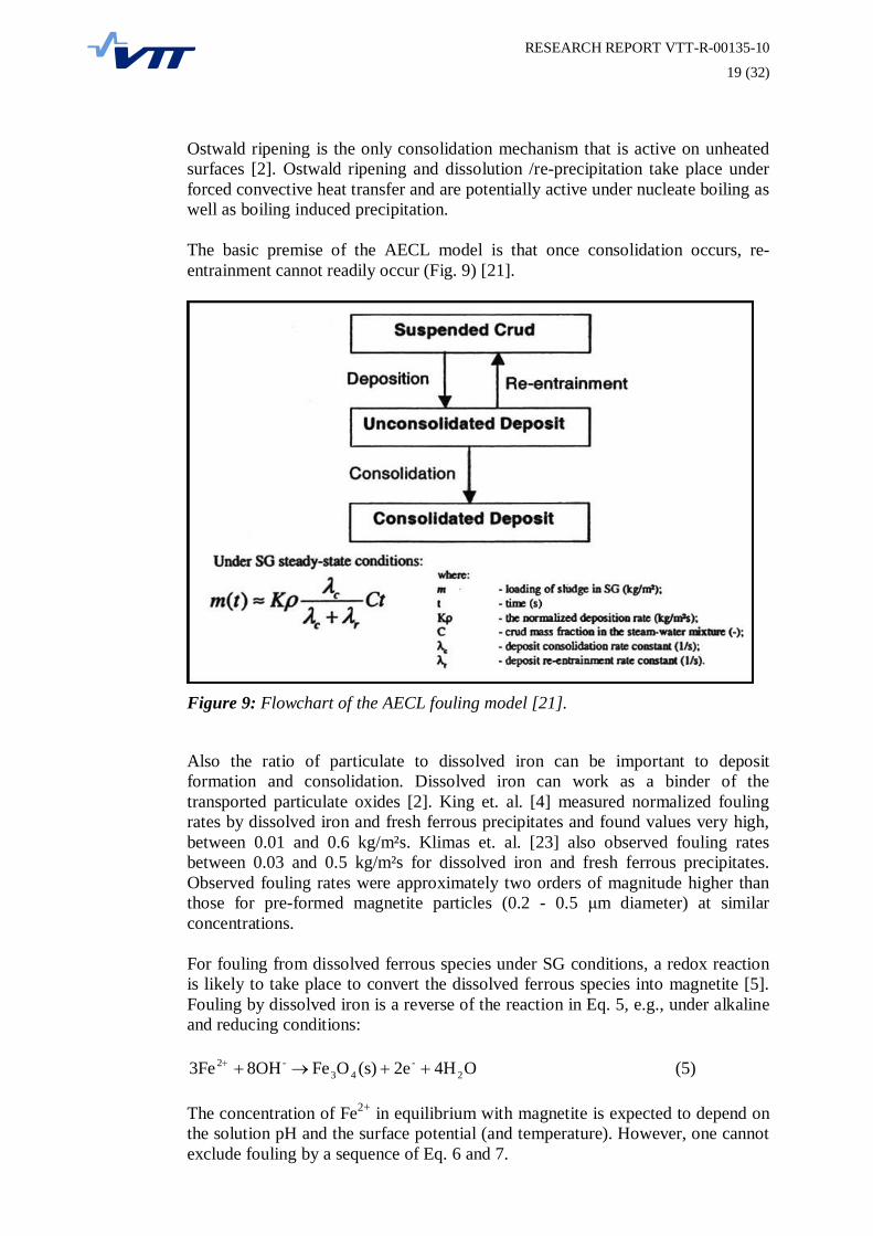
The basic premise of the AECL model is that once consolidation occurs, re-entrainment cannot readily occur (Fig. 9) [21].
Figure 9: Flowchart of the AECL fouling model [21].
Also the ratio of particulate to dissolved iron can be important to depositformation and consolidation. Dissolved iron can work as a binder of thetransported particulate oxides [2]. King et. al. [4] measured normalized foulingrates by dissolved iron and fresh ferrous precipitates and found values very high,between 0.01 and 0.6 kg/m²s. Klimas et. al. [23] also observed fouling ratesbetween 0.03 and 0.5 kg/m²s for dissolved iron and fresh ferrous precipitates.Observed fouling rates were approximately two orders of magnitude higher thanthose for pre-formed magnetite particles (0.2 - 0.5 m diameter) at similarconcentrations.
For fouling from dissolved ferrous species under SG conditions, a redox reactionis likely to take place to convert the dissolved ferrous species into magnetite [5].Fouling by dissolved iron is a reverse of the reaction in Eq. 5, e.g., under alkalineand reducing conditions:
O4H2e(s)OFe8OH3Fe 2-
43-2 (5)
The concentration of Fe2+ in equilibrium with magnetite is expected to depend onthe solution pH and the surface potential (and temperature). However, one cannotexclude fouling by a sequence of Eq. 6 and 7.

RESEARCH REPORT VTT-R-00135-10
20 (32)
(s)FeOH2OHFe 2-2 (6)
O4H2e(s)OFe2OH(s)3Fe(OH) 2-
43-
2 (7)
Thus, fouling by dissolved ferrous species is, in principle, an electrochemicalprocess, because it can generally involve transfer of charge across an electrifiedinterface and an electron transfer. The driving force for fouling (thesupersaturation at the surface) may depend on the potential of the foulingsubstrate; however, the fouling rate by dissolved iron does not have to depend onthe substrate potential for kinetic reasons (for example, it may be governed by therate of transport of ferrous species to the surface).
4.2 Formation of sludge piles
Sludge piles form on horizontal surfaces in steam generators due to thegravitational settling, entrapment and consolidation of particulate and chemicalspecies from the feedwater [1]. Sludge pile integrity is thought to be maintainedand improved by reactions among the sludge pile species or by chemical reactionswith dissolved species that tend to consolidate the sludge pile matrix. Twoexamples of such consolidations are: (1) the cementation of iron oxide particlessuch as magnetite by ferrous hydroxides according to the Schikorr reaction (Eq.8), and (2) the reaction between the dissolved iron species or magnetite andphosphate to form sodium iron phosphate.
22432 HO2H(s)OFe(s)3Fe(OH) (8)
Sludge piles form in regions where the fluid velocities are lowest [19]. The pilestend to be much more predominant on the hot leg side of the tube bundle. Insimplest terms, a deposit particle is able to settle to a horizontal surface, if itsterminal settling velocity, as dictated by the force of gravity on the particle (itsweight), can overcome the imposed velocity due to convective transport awayfrom the horizontal surface. However, analyses of steam generator fluidmechanics have shown that sludge pile formation is actually more complexphenomenon that is governed by [1].
Gravitational settling of particles with diameters approximately 10 µm orgreater. These particles are supplied to the surface from a thin layer offluid above grooving sludge pile which is replenished with particulatesfrom the well-mixed bulk fluid above.Chance incorporation of particles into sludge pile which can be predictedby use of ”sticking probabilities” which are function of physical effectsand chemical reactions between and among the particles and the sludgepile surface.Continual re-entrainment of particles due turbulent bursts at the pilesurface.
RESEARCH REPORT VTT-R-00135-10
21 (32)
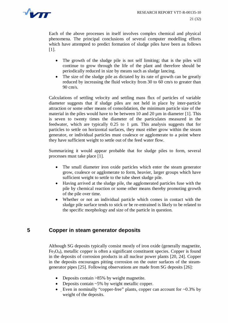
Each of the above processes in itself involves complex chemical and physicalphenomena. The principal conclusions of several computer modelling effortswhich have attempted to predict formation of sludge piles have been as follows[1].
The growth of the sludge pile is not self limiting; that is the piles willcontinue to grow through the life of the plant and therefore should beperiodically reduced in size by means such as sludge lancing.The size of the sludge pile as dictated by its rate of growth can be greatlyreduced by increasing the fluid velocity from 30 to 60 cm/s to greater than90 cm/s.
Calculations of settling velocity and settling mass flux of particles of variablediameter suggests that if sludge piles are not held in place by inter-particleattraction or some other means of consolidation, the minimum particle size of thematerial in the piles would have to be between 10 and 20 µm in diameter [1]. Thisis seven to twenty times the diameter of the particulates measured in thefeedwater, which are typically 0.25 to 1 µm. This analysis suggests that forparticles to settle on horizontal surfaces, they must either grow within the steamgenerator, or individual particles must coalesce or agglomerate to a point wherethey have sufficient weight to settle out of the feed water flow.
Summarizing it would appear probable that for sludge piles to form, severalprocesses must take place [1].
The small diameter iron oxide particles which enter the steam generatorgrow, coalesce or agglomerate to form, heavier, larger groups which havesufficient weight to settle to the tube sheet sludge pile.Having arrived at the sludge pile, the agglomerated particles fuse with thepile by chemical reaction or some other means thereby promoting growthof the pile over time.Whether or not an individual particle which comes in contact with thesludge pile surface tends to stick or be re-entrained is likely to be related tothe specific morphology and size of the particle in question.
5 Copper in steam generator deposits
Although SG deposits typically consist mostly of iron oxide (generally magnetite,Fe3O4), metallic copper is often a significant constituent species. Copper is foundin the deposits of corrosion products in all nuclear power plants [20, 24]. Copperin the deposits encourages pitting corrosion on the outer surfaces of the steam-generator pipes [25]. Following observations are made from SG deposits [26]:
Deposits contain >85% by weight magnetite.Deposits contain ~5% by weight metallic copper.Even in nominally “copper-free” plants, copper can account for ~0.3% byweight of the deposits.

RESEARCH REPORT VTT-R-00135-10
22 (32)
Copper can account for as much as 50% by weight of the deposits in somePWR steam generators.Copper in deposits is generally found as copper metal, but minor amountsof cuprite (Cu2O) and tenorite (CuO) have also been found.
Average amount of iron and copper compounds washed from 46 steam generatorsof VVER-1000 and VVER-400 reactors was 1288 kg [24]. The deposits containedon the average 27% copper. The ratio of copper and iron compounds variesbetween NPP and general trend is that those units which have operated longerhave higher amount of copper compounds in the corrosion products. The main-sources of copper entering to the steam generators at VVER-1000 and VVER-400reactors secondary loops are the low-pressure heaters.
As mentioned, copper tends to be found in scale as metallic inclusions, whichappear close to the tube scale-tube wall interface [1, 26]. This is consistent with afact that the solubility of the copper Cu(OH)+ or as an amine complex is muchlarger than that of iron species. Accordingly, copper would not precipitate orcrystallize along the tube wall, but would at the base of the scale near the boilinginterface. Also solid phase diffusion coefficients for copper are typically large incomparison to those of other metallic species. Copper ions in solution could be:(1) crystallizing preferentially on existing copper metal sites since the latticeparameter and energy of adsorption/crystallization is much lower than thatassociated with the formation of copper-iron-oxide spinels, which are rarely seenin tube deposits or (2) precipitating on the magnetite based scale and diffusing inthe solid phase until arrival at a local inclusion. Cu2+ may also contribute to thehardness of the tube scale since Cu2+ has been found to produce hard sludge piledeposits while Cu+ does not.
Events of transient periods might affect the copper in deposits and Marks andVarrin [26] have presented a qualitative working hypothesis of the effects ofshutdown, layup and startup (SLS) on SG chemistry. The hypothesis postulatesfour steps.
1. During normal operation, some corrosion in the secondary water loop occurs,introducing dissolved metal into the feedwater in minute quantities.
2. Normal operation of the SG concentrates these metal ions, forcingprecipitation of metal and oxides in the SG.
3. During SLS, the deposits in the SG are oxidized and serve as an oxygenreservoir, and oxides are also formed in other parts of the secondary system.
4. During the initial phases of operation, these oxides—together with oxidesintroduced from the secondary plant by the feedwater—are reduced, either bydirectly oxidizing the metal of the SG tubes or through introduction of oxygeninto the SG secondary bulk via various possible reactions.
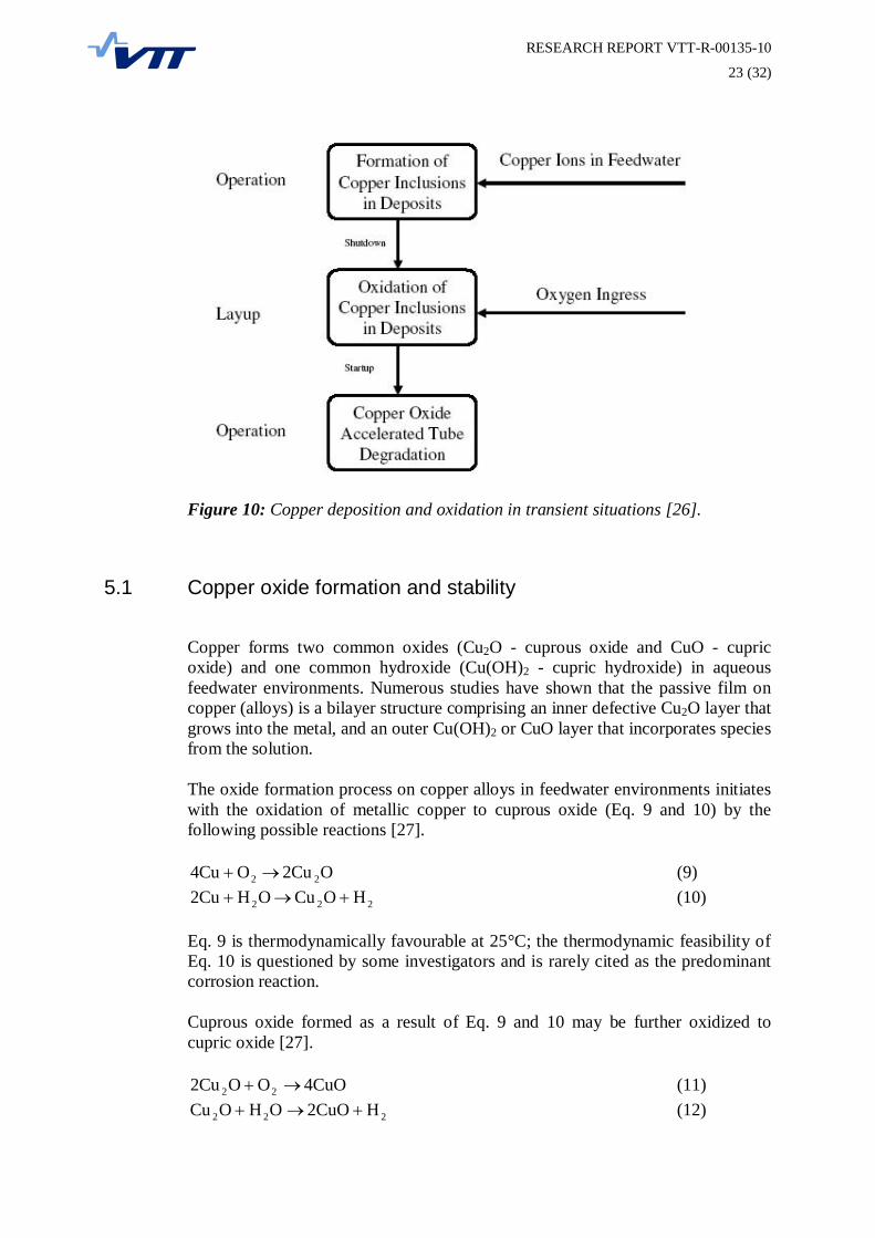
A flow diagram showing the sequence of events postulated in this hypothesis isshown in Figure 10.
RESEARCH REPORT VTT-R-00135-10
23 (32)
Figure 10: Copper deposition and oxidation in transient situations [26].
5.1 Copper oxide formation and stability
Copper forms two common oxides (Cu2O - cuprous oxide and CuO - cupricoxide) and one common hydroxide (Cu(OH)2 - cupric hydroxide) in aqueousfeedwater environments. Numerous studies have shown that the passive film oncopper (alloys) is a bilayer structure comprising an inner defective Cu2O layer thatgrows into the metal, and an outer Cu(OH)2 or CuO layer that incorporates speciesfrom the solution.
The oxide formation process on copper alloys in feedwater environments initiateswith the oxidation of metallic copper to cuprous oxide (Eq. 9 and 10) by thefollowing possible reactions [27].
O2CuO4Cu 22 (9)
222 HOCuOH2Cu (10)
Eq. 9 is thermodynamically favourable at 25°C; the thermodynamic feasibility ofEq. 10 is questioned by some investigators and is rarely cited as the predominantcorrosion reaction.
Cuprous oxide formed as a result of Eq. 9 and 10 may be further oxidized tocupric oxide [27].
4CuOOO2Cu 22 (11)
222 H2CuOOHOCu (12)

RESEARCH REPORT VTT-R-00135-10
24 (32)
Again reaction (11) is questioned by some workers and is rarely cited as thepredominant corrosion reaction. It is appropriate to consider the possibility thatcupric hydroxide [Cu(OH)2], another valence 2 compound, will form instead ofcupric oxide.
The conversion of Cu(OH)2 to CuO can be described by the Eq. 13.
OHCuOCu(OH) 22 (13)
At the temperatures of condensate and feedwater train (<200 ºC), the standardGibbs energy is negative, showing that CuO is stable relative to Cu(OH)2 [27].Thus, at feedwater temperature, Cu(OH)2 is not stable relative to CuO. This isimportant because it implies that any Cu(OH)2 that is observed in contact with thefeedwater cannot form by the hydration of CuO, but must form from a less stablespecies (such as Cu2+, Cu+, or possibly Cu2O, depending on the specificconditions).
When oxygen concentrations are high enough, both Cu2O and CuO will form on acopper or copper alloy surface [27]. The proportion of cupric oxide presentincreases with the distance from the base metal. For feedwater conditions withintypical guidelines (Table 3), (reducing conditions, low oxygen, oxygenscavenger/reducing agent, proper pH range) the oxide layer has been observed toconsist mainly of cuprous oxide. However, when cycle condition are changed byallowing oxidizing conditions (ORP > 0 mV) to exist by eliminating the oxygenscavenger or because of air-inleakage, then the proportion of cupric oxide in theouter layers increases. There is a concomitant increase in the amount of porosity,which facilitates the mechanical disruption and release of the CuO into thefeedwater.
Table 3: Normal Cycle Chemistry Limits at the Economizer Inlet for Units withMixed-Metallurgy Feedwater Systems [27].
Cycle Chemistry Parameter AVT Mixed-MetallurgypH 8.8 - 9.1Ammonia, NH3, ppm 0.15 - 0.4Cation Conductivity, µS/cm < 0.2Fe, ppb < 5 (<5)*Cu, ppb <2 (<2)*Oxygen, ppb <5 (<2)**Values in parenthesis represent the achievable and desirable limits. These valuesare achieved on mixed metallurgy units without any copper problem.
In general, the surface oxide layer found on copper and its alloys tends to be lessstable, less passive, and less protective than the iron oxide films found on ferrousalloys [27]. Destabilization of the copper oxide film involves both chemical andphysical/mechanical processes. Both cuprous and cupric oxides are subject todissolution, with higher solubility noted for the latter, at least under reducingchemical conditions. However, as already noted, CuO predominates underoxidizing conditions and the solubility of CuO under such conditions appears tobe lower than the solubility of Cu2O under reducing conditions. Nevertheless,
RESEARCH REPORT VTT-R-00135-10
25 (32)
solubility does not necessarily control release rate, so care is needed ininterpreting this information. Mechanical strain present in the oxide layer rendersit subject to fracturing as distance from the parent metal increases. As aconsequence of these processes, the diffusion rate of copper increases, leading tohigher release rates. Porous oxide layers will be subject to high rates of corrosion,while tighter layers will restrain corrosion and release of copper to the feedwater.
Typically, approaches to minimize copper corrosion and release have focused oncontrol of those species known to promote dissolution of metallic copper [27].Under reducing chemistry conditions, the process is generally expected to consistof two steps, oxidation of copper and production of copper ions. Dissolvedoxygen in the water serves as the oxidant while ammonia and, perhaps, certainneutralizing amines, serve to form stable complexes with copper ions. Complexesare distributed in secondary water system due to high solubility [25].
This concept is supported by research which demonstrates that the principalcathodic reaction for copper alloys in solutions containing ammonia is cupric ionreduction, although dissolved oxygen or ferric iron will also serve as cathodicdepolarizers [27]. It should be noted, however, that the presence of ferric ion andcupric ion in mixed metallurgy systems invariably implies the presence of oxygen,although the possibility that hydrogen evolution becomes a viable cathodicreaction must also be recognized.
Initially, in the absence of cupric ion, copper corrodes at a slow rate that isgoverned by the kinetics of oxygen reduction [27]. The cuprous ion in solution isthen complexed by ammonia to form Cu(NH3)2+ which, in turn, reacts withoxygen to form the cupric complex ion according to Eq. 14.
OH4)Cu(NH48NHO2HO)4Cu(NH -243322
23 (14)
This reaction of oxygen with the cuprous complex ion in the bulk occurs muchmore rapidly than reaction of oxygen at the metal surface because the bulkreaction is homogeneous in nature (i.e., it occurs uniformly throughout thesolution) while the reaction at the metal surface is heterogeneous. When sufficientquantities of the cupric complex ion are generated, they become the primaryoxidizing species and rapidly accelerate corrosion of susceptible copper-basealloys with the concomitant production of cuprous complex ions, Cu(NH3)2+.These reduced species are then regenerated by oxygen in the solution and thus thedissolution process is autocatalytic in the presence of oxygen.
5.2 Factors influencing copper corrosion and release activity
As indicated above, corrosion of copper and its alloys is strongly influenced bythe presence of dissolved oxygen and ammonia in solution. However, the body ofresearch available indicates that several other factors are also important. Theinteraction of all these factors is not fully understood [27].

RESEARCH REPORT VTT-R-00135-10
26 (32)
Effect of Oxygen
Most published laboratory investigations and field research indicate increasingrates of metal release from brasses and copper-nickel alloys as oxygenconcentration is increased from <30 ppb to 100-500 ppb [27].
The various research studies and field investigations show that oxygen is animportant but not necessarily dominant factor in the corrosion of copper alloys[27]. However, they also indicate the complexity of the situation and identifyother factors which will affect rates of copper corrosion and release under fossilplant operating conditions. In a properly operated unit, these would appear toinclude pH (or concentration of additive applied for pH control), presence andconcentration of oxygen scavenger, service temperature, and feedwater velocity.The effect of a selected feedwater condition will be different for each copper alloyto which it is applied. Corrosion/release rates would be affected further duringperiods of dissolved solids contamination which occur when the condenser leaks.
Oxygen scavengers appear to be beneficial since they react with dissolved oxygenand establish a reducing environment which has been shown to reduce coppercorrosion/release rates under some laboratory and field conditions [27].
Effect of pH
In many plants feedwater pH is controlled by addition of ammonia or neutralizingamines. Other species which, if present, will influence feedwater pH includecarbon dioxide (present as a consequence of condenser air inleakage), oxygenscavengers, and organics (present in the treated makeup or as breakdown productsof proprietary treatment chemicals). Laboratory investigations of copper alloycorrosion typically control pH with ammonia or an amine. The other influencingspecies are either assessed individually or excluded entirely. The oppositesituation exists in the power plant, where all species may be present but are lesseffectively controlled and may not be measured.
As indicated in Fig. 11, corrosion/release rates for copper alloys appear todecrease and then increase over the pH range of 5 to 10 [27]. The pH at whichcorrosion is minimal appears to fall between pH values of 8.0 and 9.0, but issensitive to temperature and possibly to other factors.

RESEARCH REPORT VTT-R-00135-10
27 (32)
Figure 11: Effect of pH on Copper Release Rate From 71Cu/28Zn/Sn (SoMs-71brass, or Admiralty brass) Exposed to Water Containing Carbon Dioxide (for pH<7) or ammonia (for pH>7) at Temperatures of 30°C and 90°C [27].
Copper release rates for feedwater treated with neutralizing amines wouldprobably be different than for feedwater dosed with ammonia due to presumeddifferences in copper complexing abilities, which are not well defined [27].Copper-cyclohexylamine complexes tend to precipitate from solution which mayform a protective film on the base metal. Laboratory evaluations have shown thatcopper release rates increase following a change from cyclohexylamine toammonia; whereas the release remained stable when switching from ammonia tocyclohexylamine. Use of volatile neutralizing amines instead of ammonia tocontrol condensate and feedwater pH is sometimes implemented to controlcorrosion of copper alloys. This strategy has failed in virtually every case whereno effort was made to improve dissolved oxygen control. Although some aminesexhibit better thermal stability than others, in-service degradation of thesetreatments will produce some ammonia in addition to other breakdown products,including carbon dioxide and organic acids. Another concern is the tendency ofsome amines to liberate pre-existing deposits. As a precaution, system cleanlinessshould always be evaluated as part of efforts to consider any proposed change infeedwater treatment.
Effect of Temperature
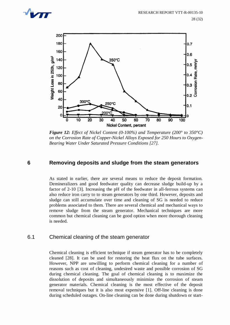
Generally, rates of copper alloy corrosion and release increase as temperature iselevated. A Japanese study of various copper-nickel alloys (Fig. 12) indicates alsothis result, with the influence of temperature becoming relatively minor as nickellevels increased.
RESEARCH REPORT VTT-R-00135-10
28 (32)
Figure 12: Effect of Nickel Content (0-100%) and Temperature (200° to 350°C)on the Corrosion Rate of Copper-Nickel Alloys Exposed for 250 Hours to Oxygen-Bearing Water Under Saturated Pressure Conditions [27].
6 Removing deposits and sludge from the steam generators
As stated in earlier, there are several means to reduce the deposit formation.Demineralizers and good feedwater quality can decrease sludge build-up by afactor of 2-10 [3]. Increasing the pH of the feedwater in all-ferrous systems canalso reduce iron carry to to steam generators by one third. However, deposits andsludge can still accumulate over time and cleaning of SG is needed to reduceproblems associated to them. There are several chemical and mechanical ways toremove sludge from the steam generator. Mechanical techniques are morecommon but chemical cleaning can be good option when more thorough cleaningis needed.
6.1 Chemical cleaning of the steam generator
Chemical cleaning is efficient technique if steam generator has to be completelycleaned [28]. It can be used for restoring the heat flux on the tube surfaces.However, NPP are unwilling to perform chemical cleaning for a number ofreasons such as cost of cleaning, undesired waste and possible corrosion of SGduring chemical cleaning. The goal of chemical cleaning is to maximize thedissolution of deposits and simultaneously minimize the corrosion of steamgenerator materials. Chemical cleaning is the most effective of the depositremoval techniques but it is also most expensive [1]. Off-line cleaning is doneduring scheduled outages. On-line cleaning can be done during shutdown or start-

RESEARCH REPORT VTT-R-00135-10
29 (32)
up when chemical solutions can be heated with the primary to secondary side heattransfer.
Chemical cleaning can be done in low temperature, 93 °C, with 10-20%ethylenediaminetetra-acetic acid (EDTA), hydrazine and corrosion inhibitor at pH7 [29, 30]. At high temperature, above 140 °C, formula contains 2-6%nitriloacetic acid (NTA) or EDTA and hydrazine at pH 9.5. Higher temperaturehas been found to accelerate magnetite deposit dissolution. Hydrazine effects onthe dissolution of the magnetite and corrosion rate of materials. Small amounts(1%) of hydrazine reduce ferric ions which decrease corrosion of the base materialand simultaneously dissolution of magnetite increases. Higher concentration ofhydrazine increases corrosion of the materials but doesn't increase depositremoval rate. Corrosion inhibitor in the solution doesn't have effect on thedissolution rate of the magnetite but decreases corrosion rate.
Rufus et al studied different formulations for iron and copper oxide depositremovals using real deposits and synthetic oxides [30]. Formulations containingEDTA, hydrazine and pH additives were used for dissolving oxides of iron. Thisformulation can only dissolve copper that exists as cupric oxide or cuprous oxide.In the presence of a carbon steel surface a part of the copper that was dissolvedwill be plated out on the carbon steel surface according to Eq. 15.
CuFeFeCu 22 (15)
Dissolution of copper and its oxides are done at high pH with complexingchemical and oxidizing environment [30]. Oxidizer can be air, oxygen orhydrogen peroxide. With air dissolved oxygen concentration is low compared tooxygen. Hydrogen peroxide was found to be the best oxidizing agent for thedissolving of copper and its oxides. Nickel dissolving was found to be slow whencompared to iron and copper. Some calcium and magnesium silicates can remainundissolved from the surfaces after chemical cleaning.
6.2 Mechanical cleaning of the steam generator
The three most common mechanical methods for removal of sludge from thesteam generators are blowdown, gas pressure and lancing [3]. The blowdownmethod usually removes only sludge that exists as suspended particles and isineffective at removing hardened sludge. It is used only for recirculating steamgenerators and uses draining system built into the steam generator.
Two gas pressure methods utilize quick acting valves which release nitrogenbelow the water surface at approximately 60 bar pressure [3]. Violentdisplacement of water with gas flushes and dislodges deposits. Deposits removedfrom the steam generator are extracted using filters or special draining procedures.
Sludge-lancing uses high-pressure water jets to remove sludge from steamgenerator [3]. In this method device with water nozzles is inserted in to the steamgenerator through inspection ports and high-pressure jets of water are used todislodge the sludge. Sludge-water mixture is pumped out from the steam

RESEARCH REPORT VTT-R-00135-10
30 (32)
generator and filtered to remove suspended sludge particles. Sludge-lancing canremove soft and some sticky sludge from the steam generators. Consolidatedsludge may be difficult to remove with lancing techniques. Tube sheet lancingtechnique has also been extended to reach locations higher in the tube bundle [1].
7 Conclusions
Deposit formation on the PWR steam generator is costly problem, which has beenextensively studied, according to literature survey. However, due to the complexnature of the fouling, there are still open questions related to the mechanisms ofdeposit formation. Especially problematic situation is in the facilities that havecopper compounds in the secondary cycle that limits the possibility to increasewater pH. The most interesting topic for further research is the role of differentamines on the flow-accelerated corrosion and deposit formation.
8 Summary
Fouling in the steam generators of pressurized water reactors can cause significantinconvenience at the nuclear power plants. Accumulation of deposits can lead tocorrosion problems, reduce heat transfer and cause tube plugging and flowproblems. Secondary-side water chemistry has developed from phosphate-basedtreatment to all-volatile water treatment, which is based on the use of ammoniaand hydrazine. Over the past 10 years, nuclear plants have also used advancedamines to reduce corrosion and deposit precursor formation.
Deposits are formed mainly from corrosion products that are transported from thesecondary-cycle. Iron oxides are the primary component in the deposits but theymay contain significant proportions of copper and copper oxides depending on theconstruction materials of the secondary-cycle. Soluble species, such as silicatesand sulphates, can concentrate and precipitate within deposits.
Flow-accelerated corrosion (FAC) on the secondary-cycle is the main source ofthe iron deposit precursors. On the FAC magnetite layer becomes thin due toenhanced dissolving at the high flow and turbulence. FAC occurs at alkalinizedand deaerated water. Temperature and pH have significant effect on the FAC, butmay be difficult to change in operating plant. Using advanced amines canalleviate FAC, but some amines can be fouling enhancers.
The formation of deposits and sludge in the steam generator involve a range ofpossible physical and chemical phenomena such as turbulent deposition, boilingdeposition, gravitational settling and re-entrainment. The deposition process iscomplex phenomena where multiple factors affect to deposit formation rate.Formed deposits and sludge can be removed from the steam generator bychemical and mechanical means.

RESEARCH REPORT VTT-R-00135-10
31 (32)
References
1. Varrin, R., Characterization of PWR Steam Generator Deposits, EPRI,Palo Alto CA, 1996. TR-106048.
2. Jevec, J.M., Klimas, S.J., King, P., Fruzzetti, K., MultivariableAssessment of Flow Accelerated Corrosion and Steam Generator Fouling:Literature Review, EPRI, Palo Alto, CA: 2003. 1003619.
3. Green, S. J., Hetsroni, G., PWR steam generators, Int. J. Multiphase Flow,21 (1995) 1-97.
4. King, P. and Jevec, J. M., Multivariable Assessment of Flow-AcceleratedCorrosion and Steam Generator Fouling: Loop Tests to Investigate theRole of Dissolved Iron in Steam Generator Fouling. EPRI, Palo Alto,CA:2006. 1013383.
5. Patel, B., Investigation of steam generator corrosion products under typicaloperating conditions, EPRI report NP-3068, May 1984.
6. Flow-Accelerated Corrosion in Power Plants, EPRI, Palo Alto, CA: 1998,TR-106611R1.
7. Laronge, T.M. and Ward, M.A., “The Basics and Not so Basics of WaterCorrosion Processes Altered by Flow Changes,” CORROSION/99, paper99345, NACE International, Houston, TX, (1999).
8. Pavageau, E.M., Effect of Hydrazine on Flow Accelerated Corrosion,EPRI, Palo Alto, CA, and EDF Electricité de France, Moret Sur Loing,France: 2005. 1008208.
9. De Bouvier, O., Effect of Redox Conditions on Flow AcceleratedCorrosion: Influence of Hydrazine and Oxygen, November 2002. EPRIReport 1002768.
10. Dooley, R.B. and Chexal, V.K., “Flow-Accelerated Corrosion,”CORROSION/99, paper 99347, NACE International, Houston, TX (1999).
11. Dooley, R.B., Flow-Accelerated Corrosion in Fossil and CombinedCycle/HRSG Plants, Power Plant Chemistry, 2008 vol.10 (2), s. 68-86.
12. Bouchacourt, M., “Impact of Water Chemistry on Corrosion-Erosion inOne-Phase and Two-Phase Flow,” Proceedings of water Chemistry inNuclear Reactor Systems 5, BNES, London, 1989 p.135.
13. Schwartz, T., Heat transfer and fouling behaviour of Siemens PWR steamgenerator - long-term operating experience, Exp. Therm Fluid Sci. 25(2001) 319-327.
14. Advanced Amine Application Guidelines, EPRI, Palo Alto, CA: 1993,TR-102952.
15. Effects of Alternate pH Control Additives on PWR Secondary CycleChemistry, EPRI, Palo Alto, CA: 1988, NP-5594.
16. Klimas, S.J., Guzonas, D., Turner, C.W: and Fruzzetti, K., Identificationand Testing of Amines for Steam Generator Chemistry and DepositControl, EPRI, Palo Alto, CA and Atomic Energy of Canada Limited,Chalk River, Ontario, Canada: 2002. 1002773.
17. Bénézeth, P., Wesolowski, D. J., Palmer, D. a., Machesky, M. L., Effect ofamines on the surface charge properties of iron oxides, J. Solution Chem38 (2009) 925-945.
18. Nasrazadani, S., Diaz, J., Stevens, J., Theimer, R., Effects of DBU,morpholine, and DMA on corrosion of low carbon steel exposed to steam,Corros. Sci. 49 (2007) 3024-3039.

RESEARCH REPORT VTT-R-00135-10
32 (32)
19. Srikantiah, G., Chappidi, P. R., Particle deposition and fouling in PWRsteam generators, Nucl. Eng. Des. 200 (2000) 285-294.
20. Oleinik, s. G., Effect of the quantity, composition, and thickness ofdeposits on the damage to the pipes of steam generators in nuclear powerplants with VVÉR reactors, At. Energ. 96 (2004) 228-233.
21. Identification and Testing of Amines for Steam Generator Chemistry andDeposit Control, EPRI, Palo Alto, CA and Atomic Energy of CanadaLimited, Chalk River, Ontario, Canada: 2002.1002773.
22. C.W. Turner, M.E. Blimkie, P.A. Lavoie, “Physical and Chemical FactorsAffecting Sludge Consolidation,” Report AECL-11674/COG-96-492-1,Atomic Energy of Canada Ltd., Chalk River, Ontario (1997).
23. Klimas, S.J Strati, G.L.., Balkrishnan, B.V: and Fruzzetti, K Identificationand Testing of Amines for Steam Generator Chemistry and DepositControl: Part 2, EPRI, Palo Alto, CA, and Atomic Energy of CanadaLimited, Chalk River, Ontario, Canada:2003. 1003624.
24. Oleinik, s. G., Influence of various factors on damage to steam-generatortubes in nuclear power plants with VVÉR reactors, At. Energ. 96 (2004)399-402.
25. Parfenov, V. V., Gorbatykh, V. P., Kinetics of pitting formation in thepresence of copper in deposits, Ther. Eng. 53 (2006) 1017-1020.
26. Marks, C. and Varrin, R. Jr., Oxidation and Reduction of Copper in SteamGenerator Deposits: Under Shutdown, Layup and Startup Conditions,EPRI, Palo Alto, CA: 2000. 1001204.
27. R. B. Dooley, B. C. Syrett, T. H. McCloskey, J. Tsou, K. J. Shields, D. D.Macdonald, State-of-Knowledge of Copper in Fossil Plant Cycles, EPRI,Palo Alto, CA, 1997, TR-108460.
28. Nordmann, F., Fiquet, J.-M., Selection criteria for the best secondarywater chemistry, Nucl. Eng. Des. 160 (1996) 193-201.
29. Hur, D. H., Choi, M. S., Chung, H. S., Kim, U. C., Optimum EDTAsolvent chemistry for iron oxide removal at 150 °C, J. Nucl. Mater. 305(2002) 220-223.
30. Rufus, A. L., Sathyaseelan, V. S., Srinivasan, M. P., Kumar, P. S., Veena,S. N., Velmurugan, S., Narasimhan, S. V., Chemistry aspects pertaining tothe application of steam generator chemical cleaning formaultion based onethylene diamine tetra acetic acid, Prog. Nucl. Energy 39 (2001) 285-303.