Development of convective heat transfer correlations for common designs of solar dryer
12
Development of convective heat transfer correlations for common designs of solar dryer Shobhana Singh, Subodh Kumar ⇑ Centre for Energy Studies, Indian Institute of Technology, Delhi, India article info Article history: Received 17 November 2010 Received in revised form 28 May 2012 Accepted 19 June 2012 Available online 27 September 2012 Keywords: Solar dryers Convective heat transfer coefficient Natural convection Forced convection Heat transfer correlations abstract The knowledge of convective heat transfer coefficient h cpf (absorber plate to flowing air) is necessary to predict or evaluate thermal performance of any solar dryer. In order to determine h cpf , laboratory models of direct (cabinet), indirect and mixed mode solar dryer are designed and constructed to perform no-load steady state experiments for natural and forced air circulation. The dryers are operated under indoor simulation conditions for absorbed thermal energy and air flow rate for the range of 300–800 W/m 2 and 1–3 m/s, respectively. Separate methods depending on mode of heat utilisation are proposed for determination of h cpf for different dryers. Correlations of h cpf in terms of dimensionless numbers are developed for each dryer operating under natural and forced convection. Levenberg–Marquardt algo- rithm is used to develop temperature dependent correlations. A close agreement between experimental and predicted h cpf values obtained from proposed correlations for natural convection dryers demonstrates their reliability. However, for forced convection dryers, there is a need to use temperature dependent Nu–Re correlation for more accurate results. The low uncertainty ranging from 0.3% to 0.8% in the deter- mination of h cpf confirms the accuracy of experimental data obtained for various dryer designs operated under different conditions. Ó 2012 Elsevier Ltd. All rights reserved. 1. Introduction In India there is a significant amount of post-harvest losses of fruits and vegetables estimated at about 35%, the monetary value of which is approximately 10 4 million dollars annually [1]. The reason may be attributed to improper handling, poor preservation strategies and insufficient storage facilities. It therefore becomes imperative to minimize these food wastes to a largest extent pos- sible and make them available in the off-season at remunerative prices. For the preservation of these agricultural products, the convective hot air drying using fossil fuels/grid-electricity is the most common technique employed in commercial dryers around the globe. However, due to unreliable or too expensive for the farmer to utilise them, more emphasis is being paid to solar energy as an alternative source for such applications [2]. In addition, it has tremendous potential especially in several regions of the world, where this source is abundantly available. In past four decades, various types of solar dryers have been designed, developed and tested with the aim of achieving faster drying of food product at minimum cost. Ekechukwu and Norton [3] presented a comprehensive review on design, construction and operation of different types of solar dryers. However, all these dryers can be broadly grouped into three major types as direct, indirect and mixed mode, depending on the arrangement of system components and mode of solar heat utilisation [4]. The operation of these dryers is primarily based on the principle of natural or forced air circulation mode. In many rural regions of developing countries, the farmers have been preferably adopting natural convection over forced mode operated dryer, since it is inexpensive to construct and easy to operate without the need of grid connected electricity and supplies of other non-renewable sources of energy. In addition, natural convection cabinet dryer of direct type has been popular among farmers especially in India because of its ability for drying 10–15 kg fruits and vegetables at household level [5,6]. Selection of solar dryer for a particular food product is primarily governed by quality requirements and economic factors. The common practice in predicting performance of solar energy system is to solve a set of several inter-related steady state heat balance equations representing various components [7]. The con- vective heat transfer coefficient, h cpf (absorber plate to flowing air) is an important parameter that is required for mathematical modelling, computer simulation and performance prediction [8]. Understanding heat transfer between plate and fluid will not only help in improving the performance of system but also serves as performance index for comparison of various designs. Higher value of h cpf is always desirable as it assists in faster drying of food prod- uct. Muneer et al. [9] discussed various aspects of heat transfer in different geometries of the physical system and types of air flow and presented related empirical correlations for convective heat 0196-8904/$ - see front matter Ó 2012 Elsevier Ltd. All rights reserved. http://dx.doi.org/10.1016/j.enconman.2012.06.017 ⇑ Corresponding author. Tel./fax: +91 11 26596409. E-mail address: [email protected] (S. Kumar). Energy Conversion and Management 64 (2012) 403–414 Contents lists available at SciVerse ScienceDirect Energy Conversion and Management journal homepage: www.elsevier.com/locate/enconman
Transcript of Development of convective heat transfer correlations for common designs of solar dryer
Energy Conversion and Management 64 (2012) 403–414
Contents lists available at SciVerse ScienceDirect
Energy Conversion and Management
journal homepage: www.elsevier .com/ locate /enconman
Development of convective heat transfer correlations for common designs ofsolar dryer
Shobhana Singh, Subodh Kumar ⇑Centre for Energy Studies, Indian Institute of Technology, Delhi, India
a r t i c l e i n f o
Article history:Received 17 November 2010Received in revised form 28 May 2012Accepted 19 June 2012Available online 27 September 2012
Keywords:Solar dryersConvective heat transfer coefficientNatural convectionForced convectionHeat transfer correlations
0196-8904/$ - see front matter � 2012 Elsevier Ltd. Ahttp://dx.doi.org/10.1016/j.enconman.2012.06.017
⇑ Corresponding author. Tel./fax: +91 11 26596409E-mail address: [email protected] (S. Kum
a b s t r a c t
The knowledge of convective heat transfer coefficient hcpf (absorber plate to flowing air) is necessary topredict or evaluate thermal performance of any solar dryer. In order to determine hcpf, laboratory modelsof direct (cabinet), indirect and mixed mode solar dryer are designed and constructed to perform no-loadsteady state experiments for natural and forced air circulation. The dryers are operated under indoorsimulation conditions for absorbed thermal energy and air flow rate for the range of 300–800 W/m2
and 1–3 m/s, respectively. Separate methods depending on mode of heat utilisation are proposed fordetermination of hcpf for different dryers. Correlations of hcpf in terms of dimensionless numbers aredeveloped for each dryer operating under natural and forced convection. Levenberg–Marquardt algo-rithm is used to develop temperature dependent correlations. A close agreement between experimentaland predicted hcpf values obtained from proposed correlations for natural convection dryers demonstratestheir reliability. However, for forced convection dryers, there is a need to use temperature dependentNu–Re correlation for more accurate results. The low uncertainty ranging from 0.3% to 0.8% in the deter-mination of hcpf confirms the accuracy of experimental data obtained for various dryer designs operatedunder different conditions.
� 2012 Elsevier Ltd. All rights reserved.
1. Introduction
In India there is a significant amount of post-harvest losses offruits and vegetables estimated at about 35%, the monetary valueof which is approximately 104 million dollars annually [1]. Thereason may be attributed to improper handling, poor preservationstrategies and insufficient storage facilities. It therefore becomesimperative to minimize these food wastes to a largest extent pos-sible and make them available in the off-season at remunerativeprices. For the preservation of these agricultural products, theconvective hot air drying using fossil fuels/grid-electricity is themost common technique employed in commercial dryers aroundthe globe. However, due to unreliable or too expensive for thefarmer to utilise them, more emphasis is being paid to solar energyas an alternative source for such applications [2]. In addition, it hastremendous potential especially in several regions of the world,where this source is abundantly available.
In past four decades, various types of solar dryers have beendesigned, developed and tested with the aim of achieving fasterdrying of food product at minimum cost. Ekechukwu and Norton[3] presented a comprehensive review on design, constructionand operation of different types of solar dryers. However, all thesedryers can be broadly grouped into three major types as direct,
ll rights reserved.
.ar).
indirect and mixed mode, depending on the arrangement of systemcomponents and mode of solar heat utilisation [4]. The operation ofthese dryers is primarily based on the principle of natural or forcedair circulation mode. In many rural regions of developing countries,the farmers have been preferably adopting natural convection overforced mode operated dryer, since it is inexpensive to constructand easy to operate without the need of grid connected electricityand supplies of other non-renewable sources of energy. In addition,natural convection cabinet dryer of direct type has been popularamong farmers especially in India because of its ability for drying10–15 kg fruits and vegetables at household level [5,6]. Selectionof solar dryer for a particular food product is primarily governedby quality requirements and economic factors.
The common practice in predicting performance of solar energysystem is to solve a set of several inter-related steady state heatbalance equations representing various components [7]. The con-vective heat transfer coefficient, hcpf (absorber plate to flowingair) is an important parameter that is required for mathematicalmodelling, computer simulation and performance prediction [8].Understanding heat transfer between plate and fluid will not onlyhelp in improving the performance of system but also serves asperformance index for comparison of various designs. Higher valueof hcpf is always desirable as it assists in faster drying of food prod-uct. Muneer et al. [9] discussed various aspects of heat transfer indifferent geometries of the physical system and types of air flowand presented related empirical correlations for convective heat
Nomenclature
Ac area of collector plate (m2)Ad area of dryer plate (m2)Dh hydraulic diameter (m)hcpf convective heat transfer coefficient from plate to air of
collector–dryer assembly (W/m2 �C)hc,cpf convective heat transfer coefficient from plate to air of
collector (W/m2 �C)hc,rpg radiative heat transfer coefficient from plate to glass of
collector (W/m2 �C)hd,cpf convective heat transfer coefficient from plate to air of
dryer chamber (W/m2 �C)hd,rpg radiative heat transfer coefficient from plate to cover of
dryer chamber (W/m2 �C)hrpg radiative heat transfer coefficient from plate to glass of
collector–dryer assembly (W/m2 �C)ka conductivity of air (W/m �C)L characteristic length (m)P wetted perimeter (m)Q heat transfer rate (W)S absorbed thermal energy flux (W/m2)Tam average ambient air temperature (�C)Tb mean bulk temperature (K)Tcp average temperature of collector plate (�C)Tcg average temperature of collector glass cover (�C)Tcf average temperature of collector hot air (�C)Tdp average temperature of dryer chamber plate (�C)
Tdg average temperature of dryer chamber cover (�C)Tdf average temperature of dryer chamber hot air (�C)Tf average temperature of hot air of collector–dryer
assembly (�C)Tg average temperature of glass cover of collector–dryer
assembly (�C)Tmf mean plate-fluid temperature (K)Tp average temperature of plate of collector–dryer assem-
bly (�C)Tw wall temperature (K)Vm mean air flow rate (m/s)Ub bottom-loss coefficient of collector–dryer assembly (W/
m2 �C)
Dimensionless numbersGr Grashof numberNu Nusselt numberPr Prandtl numberRa Rayleigh numberRe Reynolds number
Greek symbolsr Stefan Boltzman’s constant (W/m2 K4)b volumetric thermal expansion coefficient (1/K)m kinematic viscosity (m2/s)e emissivity
404 S. Singh, S. Kumar / Energy Conversion and Management 64 (2012) 403–414
transfer coefficients in terms of dimensionless numbers. Hegazy[10] developed extensive mathematical models based on energybalance concept for various designs of photo-voltaic/thermal aircollectors and studied their comparative performance. Forsonet al. [11] carried out simulation studies for performance predic-tion of single pass double duct air heater. In both of these studies,it can be noticed that published heat transfer correlations havebeen employed for computer simulation investigations. Most re-cently, Pakdaman et al. [12] developed convective heat transfercorrelation for natural convection air heater with rectangularfinned absorber plate to evaluate the thermal performance. Theapplication of published correlations developed for solar air heaterand conventional system geometries may not be amenable for per-formance prediction of solar dryers and therefore lead to erroneousresults. Goyal and Tiwari [13] presented the theoretical analysis forthermal performance of reverse flat absorber cabinet dryer assum-ing constant values of hcpf. In addition, Jain and Tiwari [14]published experimental results of convective heat transfer fromfood product to hot air for several food crops using solar green-house dryer whereas effect of shrinkage on heat transfer coefficientduring drying of potato cylinders is reported by Rahman andKumar [15]. However, these studies carried out for load conditionare highly influenced by food product moisture removal rate lead-ing to heat transfer results with a wide variation for a given testcondition.
The literature review indicates that many researchers, whilepredicting performance of solar dryers systems are constrainedto utilise convective heat transfer correlations published for stan-dard geometries of system and specific test conditions [16–18].The reason for this attempt may be attributed to scarcity of rele-vant heat transfer correlation for specific dryer design and giventest condition. The lack of research interest among the researchersmay be due to complex geometry of dryer system comprising solarair heater integrated with drying chamber and air flow pattern. Inaddition, many established correlations have neglected the effect
of air property variation due to temperature change, with an aimof providing a simpler formulation. It appears from the review ofliterature that the limited work on hcpf determination and develop-ment of heat transfer correlations for any dryer design has been re-ported so far. In the present work, modest attempt is made tobridge the research gap by development of heat transfer correla-tions for the most common dryer designs in different operatingconditions, thus enabling researchers to predict thermal perfor-mance of specific dryer with more reliable and accurate results.It is well recognised that testing of solar equipment under indoorcontrolled simulation is preferred to variable outdoor climatic con-ditions for obtaining more reliable steady state results. In addition,it provides a more meaningful and effective means of comparisonamong various designs of equipment. Further, the experimentswith no-load provide consistent results as these are not influencedby type, composition and moisture content of food product [4].Thus, in the present study, laboratory models of direct (cabinet),indirect and mixed mode solar dryers have been designed andconstructed for indoor natural and forced convection experimentsunder no-load condition. The major objectives of present study are:(i) to carry out no-load steady state indoor experiments on threemost common designs of solar dryer for different operating condi-tions (ii) to propose separate methodology for the determination ofconvective heat transfer coefficient, hcpf for each dryer design (iii)to develop correlations for hcpf in terms of dimensionless numbersfor different solar dryers and validate their reliability through com-parison with experimental results.
2. Experimental arrangement
2.1. Construction details of dryers
The cabinet, indirect and mixed mode laboratory models ofsolar dryer were fabricated for experimental investigation. The
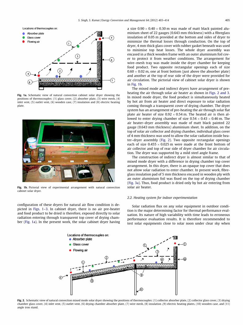
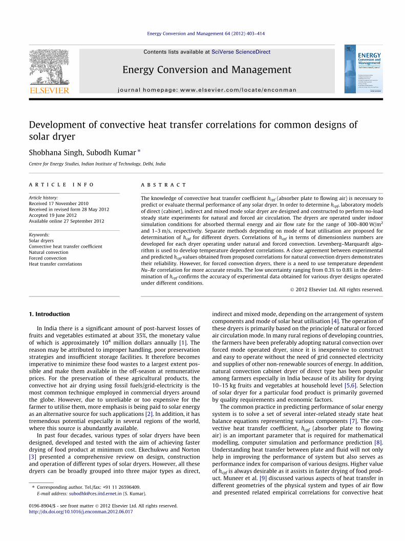
Fig. 1a. Schematic view of natural convection cabinet solar dryer showing thepositions of thermocouples: (1) glass cover, (2) absorber plate, (3) wire mesh, (4)inlet vent, (5) outlet vent, (6) wooden case, (7) insulation and (8) electric heatingplate.
Fig. 1b. Pictorial view of experimental arrangement with natural convectioncabinet solar dryer.
S. Singh, S. Kumar / Energy Conversion and Management 64 (2012) 403–414 405
configuration of these dryers for natural air flow condition is de-picted in Figs. 1–3. In cabinet dryer, there is no air pre-heaterand food product to be dried is therefore, exposed directly to solarradiation entering through transparent top cover of drying cham-ber (Fig. 1a). In the present work, the solar cabinet dryer having
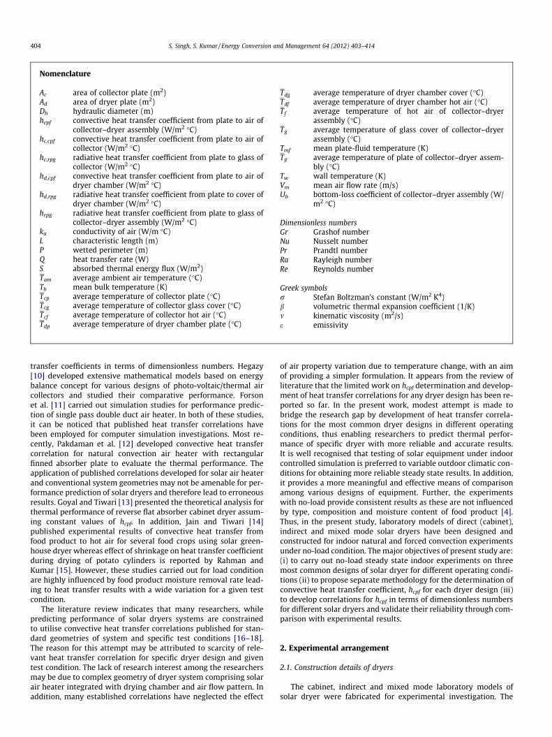
Fig. 2. Schematic view of natural convection mixed mode solar dryer showing the positiochamber glass cover, (4) inlet vent, (5) outlet vent, (6) drying chamber absorber plate, (angle iron stand.
a size 0.90 � 0.40 � 0.30 m was made of matt black painted alu-minium sheet of 22 gauges (0.643 mm thickness) with a fibreglassinsulation of 0.05 m provided at the bottom and sides of dryer tominimize the thermal losses through conduction. On the top ofdryer, 4 mm thick glass cover with rubber gasket beneath was usedto minimise top heat losses. The whole dryer assembly wasencased in a thick wooden frame with an outer aluminium foil cov-er to protect it from weather conditions. The arrangement forwire–mesh tray was made inside the dryer chamber for keepingfood product. Two opposite rectangular openings each of size0.60 � 0.02 m, one at front bottom (just above the absorber plate)and another at the top of rear side of the dryer were provided forair circulation. The pictorial view of cabinet solar dryer is shownin Fig. 1b.
The mixed mode and indirect dryers have arrangement of pre-heating the air through solar air heater as shown in Figs. 2 and 3.In mixed mode dryer, the food product is simultaneously heatedby hot air from air heater and direct exposure to solar radiationcoming through a transparent cover of drying chamber. The dryersystem has an arrangement of pre-heating the air through solar flatplate air heater of size 0.92 � 0.54 m. The heated air is then al-lowed to enter drying chamber of size 0.54 � 0.43 � 0.46 m. Theair heater–dryer assembly was made of matt black painted 22gauge (0.643 mm thickness) aluminium sheet. In addition, on thetop of solar air collector and drying chamber, individual glass coverof 4 mm thickness was used to allow the solar radiation inside hea-ter–dryer assembly (Fig. 2). Two opposite rectangular openingseach of size 0.455 � 0.025 m were made at the front bottom ofair collector and top of rear side of dryer chamber for air circula-tion. The dryer was supported by a mild steel angle frame.
The construction of indirect dryer is almost similar to that ofmixed mode dryer with a difference in drying chamber top coverarrangement. In this dryer, there is an opaque top cover that doesnot allow solar radiation to enter chamber. In present work, fibre-glass insulation pad of 5 mm thickness encased in wooden ply withan outer aluminium foil was fixed on the top of drying chamber(Fig. 3a). Thus, food product is dried only by hot air entering fromsolar air heater.
2.2. Heating system for indoor experimentation
Solar radiation flux on any solar equipment in outdoor condi-tion is the major determining factor for thermal performance eval-uation. Its nature of high variability with time leads to erroneousperformance evaluation results. It is therefore recommended totest solar equipments close to solar noon under clear sky when
ns of thermocouples: (1) collector absorber plate, (2) collector glass cover, (3) drying7) wire mesh, (8) insulation ,(9) electric heating plates, (10) wooden case, and (11)
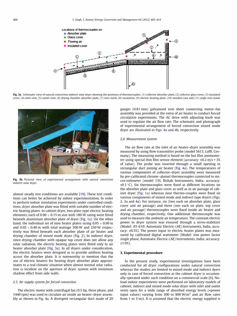
Fig. 3a. Schematic view of natural convection indirect solar dryer showing the positions of thermocouples: (1) collector absorber plate, (2) collector glass cover, (3) insulatedcover, (4) inlet vent, (5) outlet vent, (6) drying chamber absorber plate, (7) wire mesh, (8) insulation, (9) electric heating plate, (10) wooden case and (11) angle iron stand.
Fig. 3b. Pictorial view of experimental arrangement with natural convectionindirect solar dryer.
406 S. Singh, S. Kumar / Energy Conversion and Management 64 (2012) 403–414
almost steady test conditions are available [19]. These test condi-tions can better be achieved by indoor experimentation. In orderto perform indoor simulation experiments under controlled condi-tions, dryer absorber plate was fitted with suitable number of elec-tric heating plates. In cabinet dryer, two plate-type electric heatingelements, each of 0.90 � 0.15 m size with 180 W rating were fittedbeneath aluminium absorber plate of dryer (Fig. 1a). On the otherhand, the individual set of nine heater plates sizing 0.05 � 0.90 mand 0.05 � 0.40 m with total wattage 500 W and 250 W respec-tively was fitted beneath each absorber plate of air heater anddrying chamber of mixed mode dryer (Fig. 2). In indirect dryer,since drying chamber with opaque top cover does not allow anysolar radiation, the electric heating plates were fitted only to airheater absorber plate (Fig. 3a). In all dryers under consideration,the electric heaters were designed as to provide uniform heatingacross the absorber plate. It is noteworthy to mention that theuse of electric heaters for heating dryer absorber plate approxi-mates to a real climatic situation when almost normal solar radia-tion is incident on the aperture of dryer system with minimumshadow effect from side walls.
2.3. Air supply system for forced convection
The electric motor with centrifugal fan (0.5 hp, three phase, and1440 rpm) was used to circulate air inside air heater–dryer assem-bly as shown in Fig. 4a. A divergent rectangular duct made of 20
gauges (0.81 mm) galvanised iron sheet connecting motor–fanassembly was provided at the entry of air heater to conduct forcedcirculation experiments. The AC drive with adjusting knob wasused to regulate the air flow rate. The schematic and photographof experimental arrangement of forced convection mixed modedryer are illustrated in Figs. 4a and 4b, respectively.
2.4. Measurement system
The air flow rate at the inlet of air heater–dryer assembly wasmeasured by using flow transmitter probe (model 5613, Lufft, Ger-many). The measuring method is based on the hot film anemome-ter using special thin film sensor element (accuracy: ±0.2 m/s + 3%of value). The probe was inserted through a small opening inrectangular duct joining air heater (Fig. 4a). The temperatures ofvarious components of collector–dryer assembly were measuredby pre-calibrated chrome–alumel thermocouples connected to mi-cro-voltmeter (model 13S, Rishab Instruments, India; accuracy:±0.1 �C). Six thermocouples were fixed at different locations onthe absorber plate and glass cover as well as in air passage of cab-inet dryer (Fig. 1a) whereas nine thermo-couples were fixed onvarious components of mixed mode and indirect type dryers (Figs.2, 3a and 4a). For instance, six (two each on absorber plate, glasscover and air passage) and three (one each on plate, top coverand air passage) thermocouples were fixed inside air heater anddrying chamber, respectively. One additional thermocouple wasused to measure the ambient air temperature. The constant electricpower to dryer system was ensured through a servo-stabilizer(Model: AY-610; Automatic Electric-(AE) Instruments, India, accu-racy: ±0.5%). The power input to electric heater plates was mea-sured by calibrated digital wattmeter (Model: low power factorsingle phase, Automatic Electric-(AE) Instruments, India; accuracy:±1.0%).
3. Experimental procedure
In the present study, experimental investigations have beenconducted for all dryer configurations under natural convectionwhereas the studies are limited to mixed mode and indirect dyersonly in case of forced convection as the cabinet dryer is occasion-ally operated under such condition on a commercial scale [6]. No-load indoor experiments were performed on laboratory models ofcabinet, indirect and mixed mode solar dryer with inlet and outletvents open for a wide range of absorbed energy levels (=powerinput values) varying from 300 to 800 W/m2 and air flow ratesfrom 1 to 3 m/s. It is assumed that the electric energy supplied is
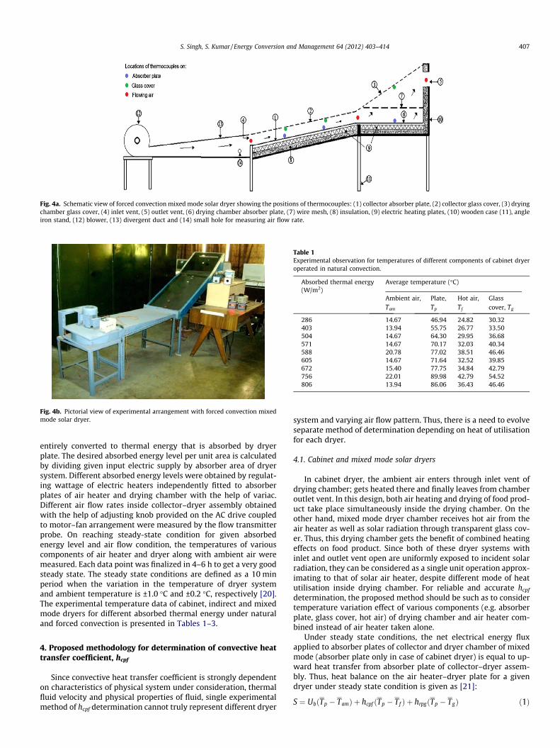
Fig. 4a. Schematic view of forced convection mixed mode solar dryer showing the positions of thermocouples: (1) collector absorber plate, (2) collector glass cover, (3) dryingchamber glass cover, (4) inlet vent, (5) outlet vent, (6) drying chamber absorber plate, (7) wire mesh, (8) insulation, (9) electric heating plates, (10) wooden case (11), angleiron stand, (12) blower, (13) divergent duct and (14) small hole for measuring air flow rate.
Fig. 4b. Pictorial view of experimental arrangement with forced convection mixedmode solar dryer.
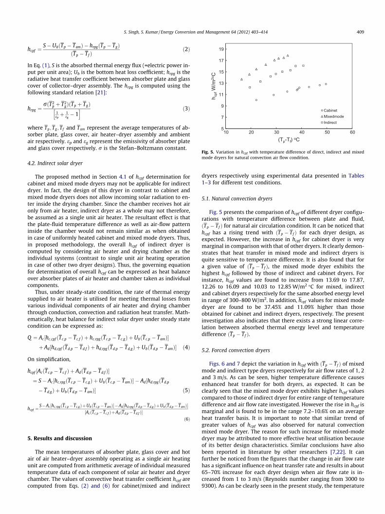
Table 1Experimental observation for temperatures of different components of cabinet dryeroperated in natural convection.
Absorbed thermal energy(W/m2)
Average temperature (�C)
Ambient air,Tam
Plate,Tp
Hot air,Tf
Glasscover, Tg
286 14.67 46.94 24.82 30.32403 13.94 55.75 26.77 33.50504 14.67 64.30 29.95 36.68571 14.67 70.17 32.03 40.34588 20.78 77.02 38.51 46.46605 14.67 71.64 32.52 39.85672 15.40 77.75 34.84 42.79756 22.01 89.98 42.79 54.52806 13.94 86.06 36.43 46.46
S. Singh, S. Kumar / Energy Conversion and Management 64 (2012) 403–414 407
entirely converted to thermal energy that is absorbed by dryerplate. The desired absorbed energy level per unit area is calculatedby dividing given input electric supply by absorber area of dryersystem. Different absorbed energy levels were obtained by regulat-ing wattage of electric heaters independently fitted to absorberplates of air heater and drying chamber with the help of variac.Different air flow rates inside collector–dryer assembly obtainedwith the help of adjusting knob provided on the AC drive coupledto motor–fan arrangement were measured by the flow transmitterprobe. On reaching steady-state condition for given absorbedenergy level and air flow condition, the temperatures of variouscomponents of air heater and dryer along with ambient air weremeasured. Each data point was finalized in 4–6 h to get a very goodsteady state. The steady state conditions are defined as a 10 minperiod when the variation in the temperature of dryer systemand ambient temperature is ±1.0 �C and ±0.2 �C, respectively [20].The experimental temperature data of cabinet, indirect and mixedmode dryers for different absorbed thermal energy under naturaland forced convection is presented in Tables 1–3.
4. Proposed methodology for determination of convective heattransfer coefficient, hcpf
Since convective heat transfer coefficient is strongly dependenton characteristics of physical system under consideration, thermalfluid velocity and physical properties of fluid, single experimentalmethod of hcpf determination cannot truly represent different dryer
system and varying air flow pattern. Thus, there is a need to evolveseparate method of determination depending on heat of utilisationfor each dryer.
4.1. Cabinet and mixed mode solar dryers
In cabinet dryer, the ambient air enters through inlet vent ofdrying chamber; gets heated there and finally leaves from chamberoutlet vent. In this design, both air heating and drying of food prod-uct take place simultaneously inside the drying chamber. On theother hand, mixed mode dryer chamber receives hot air from theair heater as well as solar radiation through transparent glass cov-er. Thus, this drying chamber gets the benefit of combined heatingeffects on food product. Since both of these dryer systems withinlet and outlet vent open are uniformly exposed to incident solarradiation, they can be considered as a single unit operation approx-imating to that of solar air heater, despite different mode of heatutilisation inside drying chamber. For reliable and accurate hcpf
determination, the proposed method should be such as to considertemperature variation effect of various components (e.g. absorberplate, glass cover, hot air) of drying chamber and air heater com-bined instead of air heater taken alone.
Under steady state conditions, the net electrical energy fluxapplied to absorber plates of collector and dryer chamber of mixedmode (absorber plate only in case of cabinet dryer) is equal to up-ward heat transfer from absorber plate of collector–dryer assem-bly. Thus, heat balance on the air heater–dryer plate for a givendryer under steady state condition is given as [21]:
S ¼ UbðTp � TamÞ þ hcpf ðTp � Tf Þ þ hrpgðTp � TgÞ ð1Þ
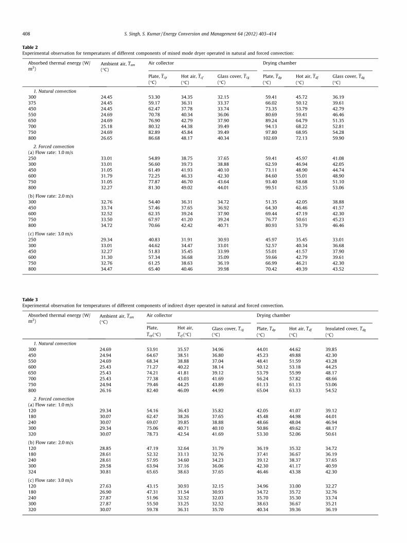
Table 2Experimental observation for temperatures of different components of mixed mode dryer operated in natural and forced convection:
Absorbed thermal energy (W/m2)
Ambient air, Tam
(�C)Air collector Drying chamber
Plate, Tcp
(�C)Hot air, Tcf
(�C)Glass cover, Tcg
(�C)Plate, Tdp
(�C)Hot air, Tdf
(�C)Glass cover, Tdg
(�C)
1. Natural convection300 24.45 53.30 34.35 32.15 59.41 45.72 36.19375 24.45 59.17 36.31 33.37 66.02 50.12 39.61450 24.45 62.47 37.78 33.74 73.35 53.79 42.79550 24.69 70.78 40.34 36.06 80.69 59.41 46.46650 24.69 76.90 42.79 37.90 89.24 64.79 51.35700 25.18 80.32 44.38 39.49 94.13 68.22 52.81750 24.69 82.89 45.84 39.49 97.80 68.95 54.28800 26.65 86.68 48.17 40.34 102.69 72.13 59.90
2. Forced convection(a) Flow rate: 1.0 m/s250 33.01 54.89 38.75 37.65 59.41 45.97 41.08300 33.01 56.60 39.73 38.88 62.59 46.94 42.05450 31.05 61.49 41.93 40.10 73.11 48.90 44.74600 31.79 72.25 46.33 42.30 84.60 55.01 48.90750 31.05 77.87 46.70 43.64 93.40 58.68 51.10800 32.27 81.30 49.02 44.01 99.51 62.35 53.06
(b) Flow rate: 2.0 m/s300 32.76 54.40 36.31 34.72 51.35 42.05 38.88450 33.74 57.46 37.65 36.92 64.30 46.46 41.57600 32.52 62.35 39.24 37.90 69.44 47.19 42.30750 33.50 67.97 41.20 39.24 76.77 50.61 45.23800 34.72 70.66 42.42 40.71 80.93 53.79 46.46
(c) Flow rate: 3.0 m/s250 29.34 40.83 31.91 30.93 45.97 35.45 33.01300 33.01 44.62 34.47 33.01 52.57 40.34 36.68450 32.27 51.83 35.45 33.99 55.01 41.57 37.90600 31.30 57.34 36.68 35.09 59.66 42.79 39.61750 32.76 61.25 38.63 36.19 66.99 46.21 42.30800 34.47 65.40 40.46 39.98 70.42 49.39 43.52
Table 3Experimental observation for temperatures of different components of indirect dryer operated in natural and forced convection.
Absorbed thermal energy (W/m2)
Ambient air, Tam
(�C)Air collector Drying chamber
Plate,Tcp(�C)
Hot air,Tcf (�C)
Glass cover, Tcg
(�C)Plate, Tdp
(�C)Hot air, Tdf
(�C)Insulated cover, Tdg
(�C)
1. Natural convection300 24.69 53.91 35.57 34.96 44.01 44.62 39.85450 24.94 64.67 38.51 36.80 45.23 49.88 42.30550 24.69 68.34 38.88 37.04 48.41 51.59 43.28600 25.43 71.27 40.22 38.14 50.12 53.18 44.25650 25.43 74.21 41.81 39.12 53.79 55.99 48.17700 25.43 77.38 43.03 41.69 56.24 57.82 48.66750 24.94 79.46 44.25 43.89 61.13 61.13 53.06800 26.16 82.40 46.09 44.99 65.04 63.33 54.52
2. Forced convection(a) Flow rate: 1.0 m/s120 29.34 54.16 36.43 35.82 42.05 41.07 39.12180 30.07 62.47 38.26 37.65 45.48 44.98 44.01240 30.07 69.07 39.85 38.88 48.66 48.04 46.94300 29.34 75.06 40.71 40.10 50.86 49.62 48.17320 30.07 78.73 42.54 41.69 53.30 52.06 50.61
(b) Flow rate: 2.0 m/s120 28.85 47.19 32.64 31.79 36.19 35.32 34.72180 28.61 52.32 33.13 32.76 37.41 36.67 36.19240 28.61 57.95 34.60 34.23 39.12 38.37 37.65300 29.58 63.94 37.16 36.06 42.30 41.17 40.59324 30.81 65.65 38.63 37.65 46.46 43.38 42.30
(c) Flow rate: 3.0 m/s120 27.63 43.15 30.93 32.15 34.96 33.00 32.27180 26.90 47.31 31.54 30.93 34.72 35.72 32.76240 27.87 51.96 32.52 32.03 35.70 35.30 33.74300 27.87 55.50 33.25 32.52 38.63 36.67 35.21320 30.07 59.78 36.31 35.70 40.34 39.36 36.19
408 S. Singh, S. Kumar / Energy Conversion and Management 64 (2012) 403–414
5
7
9
11
13
15
17
19
10 20 30 40 50 60
h cpf
W/m
2oC
(Tp-Tf) oC
CabinetMixedmodeIndirect
Fig. 5. Variation in hcpf with temperature difference of direct, indirect and mixedmode dryers for natural convection air flow condition.
S. Singh, S. Kumar / Energy Conversion and Management 64 (2012) 403–414 409
hcpf ¼S� UbðTp � TamÞ � hrpgðTp � TgÞ
ðTp � Tf Þð2Þ
In Eq. (1), S is the absorbed thermal energy flux (=electric power in-put per unit area); Ub is the bottom heat loss coefficient; hrpg is theradiative heat transfer coefficient between absorber plate and glasscover of collector–dryer assembly. The hrpg is computed using thefollowing standard relation [21]:
hrpg ¼rðT2
p þ T2gÞðTp þ TgÞ
1epþ 1
eg� 1
h i ð3Þ
where Tp; Tg ; Tf and Tam represent the average temperatures of ab-sorber plate, glass cover, air heater–dryer assembly and ambientair respectively. ep and eg represent the emissivity of absorber plateand glass cover respectively. r is the Stefan–Boltzmann constant.
4.2. Indirect solar dryer
The proposed method in Section 4.1 of hcpf determination forcabinet and mixed mode dryers may not be applicable for indirectdryer. In fact, the design of this dryer in contrast to cabinet andmixed mode dryers does not allow incoming solar radiation to en-ter inside the drying chamber. Since the chamber receives hot aironly from air heater, indirect dryer as a whole may not therefore,be assumed as a single unit air heater. The resultant effect is thatthe plate-fluid temperature difference as well as air-flow patterninside the chamber would not remain similar as when obtainedin case of uniformly heated cabinet and mixed mode dryers. Thus,in proposed methodology, the overall hcpf of indirect dryer iscomputed by considering air heater and drying chamber as theindividual systems (contrast to single unit air heating operationin case of other two dryer designs). Thus, the governing equationfor determination of overall hcpf can be expressed as heat balanceover absorber plates of air heater and chamber taken as individualcomponents.
Thus, under steady-state condition, the rate of thermal energysupplied to air heater is utilised for meeting thermal losses fromvarious individual components of air heater and drying chamberthrough conduction, convection and radiation heat transfer. Math-ematically, heat balance for indirect solar dryer under steady statecondition can be expressed as:
Q ¼ Ac½hc;cpf ðTc;p � Tc;f Þ þ hc;rpgðTc;p � Tc;gÞ þ UbðTc;p � TamÞ�þ Ad½hd;cpf ðTd;p � Td;f Þ þ hd;rpgðTd;p � Td;gÞ þ UbðTd;p � TamÞ� ð4Þ
On simplification,
hcpf ½AcðTc;p � Tc;f Þ þ AdðTd;p � Td;f Þ�¼ S� Ac½hc;rpgðTc;p � Tc;gÞ þ UbðTc;p � TamÞ� � Ad½hd;rpgðTd;p
� Td;gÞ þ UbðTd;p � TamÞ� ð5Þ
hcpf ¼S�Ac ½hc;rpgðTc;p�Tc;gÞþUbðTc;p�TamÞ��Ad½hd;rpgðTd;p�Td;gÞþUbðTd;p�TamÞ�
½AcðTc;p�Tc;f ÞþAdðTd;p�Td;f Þ�ð6Þ
5. Results and discussion
The mean temperatures of absorber plate, glass cover and hotair of air heater–dryer assembly operating as a single air heatingunit are computed from arithmetic average of individual measuredtemperature data of each component of solar air heater and dryerchamber. The values of convective heat transfer coefficient hcpf arecomputed from Eqs. (2) and (6) for cabinet/mixed and indirect
dryers respectively using experimental data presented in Tables1–3 for different test conditions.
5.1. Natural convection dryers
Fig. 5 presents the comparison of hcpf of different dryer configu-rations with temperature difference between plate and fluid,ðTp � Tf Þ for natural air circulation condition. It can be noticed thathcpf has a rising trend with ðTp � Tf Þ for each dryer design, asexpected. However, the increase in hcpf for cabinet dryer is verymarginal in comparison with that of other dryers. It clearly demon-strates that heat transfer in mixed mode and indirect dryers isquite sensitive to temperature difference. It is also found that fora given value of ðTp � Tf Þ, the mixed mode dryer exhibits thehighest hcpf followed by those of indirect and cabinet dryers. Forinstance, hcpf values are found to increase from 13.69 to 17.87,12.26 to 16.09 and 10.03 to 12.85 W/m2 �C for mixed, indirectand cabinet dryers respectively for the same absorbed energy levelin range of 300–800 W/m2. In addition, hcpf values for mixed modedryer are found to be 37.45% and 11.09% higher than thoseobtained for cabinet and indirect dryers, respectively. The presentinvestigation also indicates that there exists a strong linear corre-lation between absorbed thermal energy level and temperaturedifference ðTp � Tf Þ.
5.2. Forced convection dryers
Figs. 6 and 7 depict the variation in hcpf with ðTp � Tf Þ of mixedmode and indirect type dryers respectively for air flow rates of 1, 2and 3 m/s. As can be seen, higher temperature difference causesenhanced heat transfer for both dryers, as expected. It can beclearly seen that the mixed mode dryer exhibits higher hcpf valuescompared to those of indirect dryer for entire range of temperaturedifference and air flow rate investigated. However the rise in hcpf ismarginal and is found to be in the range 7.2–10.6% on an averageheat transfer basis. It is important to note that similar trend ofgreater values of hcpf was also observed for natural convectionmixed mode dryer. The reason for such increase for mixed-modedryer may be attributed to more effective heat utilisation becauseof its better design characteristics. Similar conclusions have alsobeen reported in literature by other researchers [7,22]. It canfurther be noticed from the figures that the change in air flow ratehas a significant influence on heat transfer rate and results in about65–70% increase for each dryer design when air flow rate is in-creased from 1 to 3 m/s (Reynolds number ranging from 3000 to9300). As can be clearly seen in the present study, the temperature

0
5
10
15
20
25
30
35
5 15 25 35 45
h cpf
(W/m
2oC
)
(Tp-Tf) (oC)
1 m/s2 m/s3 m/s
Fig. 6. Variation in hcpf with temperature difference of mixed mode dryer fordifferent air flow rates.
0
5
10
15
20
25
30
35
5 15 25 35 45
h cpf
(W/m
2oC
)
(Tp-Tf) (oC)
1 m/s2 m/s3 m/s
Fig. 7. Variation in hcpf with temperature difference of indirect dryer for differentair flow rates.
410 S. Singh, S. Kumar / Energy Conversion and Management 64 (2012) 403–414
difference and air flow rate have varying degree of increasing influ-ence on heat transfer for each design of dryer.
5.3. Development of convective heat transfer correlations for hcpf
In practice, it is observed that the application of correlations iswidely preferred by design engineers for optimisation of systemsince it helps in evaluating the parameters in simple and accurateway without performing the experiments. In the literature, manyheat transfer correlations exist for conventional geometries ofsystem and test conditions. In the present study, attempt is madeto develop the correlations for hcpf in terms of dimensionless num-bers for each dryer operating under natural and forced convectionmode.
5.3.1. Dryer design specific correlations of hcpf
5.3.1.1. Natural convection dryers. The convective heat transfercoefficient hcpf for natural convection in terms of dimensionlessnumbers (Nusselt number Nu, Grashof number, Gr and Prandtlnumber, Pr) is usually expressed through following relation [23]:
Nu ¼ hcpf � Lka
¼ CðGr � PrÞn ¼ CðRaÞn ð7aÞ
The value of the constants C and n depends on the geometry of thedryer system investigated and air flow regime respectively. TheGrashof number, Gr is given by the relation [23],
Gr ¼ gbðTp � Tf ÞL3
v2 ð7bÞ
where L is the characteristic length.The experimental temperature data and hcpf of each dryer de-
sign for different absorbed energy are used in determination ofRayleigh and Nusselt numbers. The different physical propertiesof air such as conductivity (ka), kinematic viscosity (m) and coeffi-cient of thermal expansion (b) are evaluated at mean plate-fluid
temperature, Tmf ¼ðTpþTf Þ
2 . The empirical relations for these proper-
ties used in the analysis are: ka ¼ 0:000206T0:85mf ;
m ¼ 9:0� 10�10T1:72mf and b ¼ 1
Tmf[24]. The Prandtl number, Pr is al-
most constant and is taken as 0.7 for the range of temperature con-sidered. The constants C and n in Eq. (7) are found by linearregression analysis of hcpf and Rayleigh number data for differenttemperatures of each dryer. The proposed correlation for eachdryer design is given as:
(i) Cabinet dryer
Nu ¼ 0:106Ra0:425 for 1:4� 106 < Ra < 2:1� 106 ð8aÞ
(ii) Mixed mode dryer
Nu ¼ 0:0115Ra0:529 for 2:0� 108 < Ra < 2:9� 108 ð8bÞ
(iii) Indirect dryer
Nu ¼ 0:0092Ra0:552 for 1:3� 108 < Ra < 2:0� 108 ð8cÞ
5.3.1.2. Forced convection dryers. In order to develop correlation forhcpf of forced convection dryer, the general relation involvingdimensionless Nusselt number, Nu and Reynolds number, Re forrectangular duct is used and given as [23]:
Nu ¼ hcpf � Dh
ka¼ CRemPrn ð9aÞ
The Reynolds number, Re is given by the standard relation [23],
Re ¼ Vm � Dh
v ð9bÞ
The hydraulic diameter Dh is used for characteristic length and gi-ven by the relation:
Dh ¼4AP
ð9cÞ
where A and P are area and perimeter of wetted surface, respec-tively. Vm is the mean air flow rate.
The experimental temperature data and hcpf of mixed mode andindirect dryers for different air flow rates presented in Tables 2 and3 are used for determination of dimensionless numbers of Eq. (9a).For heating of fluid, the exponent of Prandtl number n is assumedto be equal to 0.4 [25]. The constants C and m of Eq. (9a) of eachdryer design are determined by linear regression analysis of hcpf
and Reynolds number data for different temperatures and air flowrate of each dryer. The proposed correlations are given as:
(i) Mixed mode dryer
Nu ¼ 0:917Re0:458Pr0:4 ð10aÞ
(ii) Indirect dryer
Nu ¼ 0:707Re0:477Pr0:4 ð10bÞ
The air properties namely, thermal conductivity (ka) and kinematicviscosity ðmÞ are expected to vary with temperature significantly inforced air circulation and consequently affect the flow and heat
20
)
S. Singh, S. Kumar / Energy Conversion and Management 64 (2012) 403–414 411
transfer characteristics. In order to take air property variationeffect due to temperature change into account, the temperaturecorrection factor Tw
Tb
� �pis needed to be incorporated in the standard
Nu–Re relation (Eq. (9a)). The modified relation can be written as[25]:
5
10
15
5 15 25 35 45 55
h cpf
(W/m
2oC
(Tp-Tf) (oC)
Exp.CabinetExp.IndirectExp.MixedmodePridicted
Fig. 8. Comparison between experimental and predicted hcpf of different dryers fornatural convection air flow condition.
Nu ¼ hcpf � Dh
ka¼ CRemPrn Tw
Tb
� �p
ð11Þ
where Tw and Tb represent the temperatures of surface wall andaverage bulk air, respectively. All the properties of air are evaluatedat bulk-temperature Tb ¼ ðTiþToÞ
2 [23]. The values of constants C, m, n,and p in Eq. (11) are obtained by non-linear regression analysisusing Levenberg–Marquardt optimisation algorithm. The proposedcorrelations of mixed mode and indirect dryers (Reynolds numberranging from 3000 to 9300) are given as:
(i) Mixed mode dryer
Table 4
Nu ¼ 0:0966Re0:667Pr0:4 Tw
Tb
� �6:0
ð12aÞ
Results of root mean square error (RMSE) estimation in convective heat transfer
(ii) Indirect dryer coefficient, hcpf for various proposed correlations.Type ofdryer
Root mean square error (RMSE) in hcpf (W/m2 �C)
Nu ¼ 0:043Re0:733Pr0:4 TwTb
� �11:5
ð12bÞ
NaturalconvectionForced convection
Correlation withouttemperaturecorrection effect
Correlation withtemperaturecorrection factor
1 m/s 2 m/s 3 m/s 1 m/s 2 m/s 3 m/s
(a) For individual design specific correlationsi. Cabinet
dryer0.165 NAa NAa NAa NAa NAa NAa
ii. Indirectdryer
0.212 1.696 2.852 3.397 0.781 0.731 1.145
iii. Mixedmodedryer
0.136 2.050 2.448 3.437 0.928 0.706 0.799
(b) For design independent correlations1.004 2.169 2.922 3.802 1.031 1.296 1.551
a The forced convection studies were performed only for indirect and mixedmode dryers.
5.3.2. Dryer design independent correlationsIn the present study, the suitability of single design indepen-
dent correlation representing heat transfer behaviour of all dryerdesigns taken together in contrast to individual correlation pro-posed for each dryer design (Eqs. (8)–(12)) is also investigated. Inother words, the proposed single correlation should be capable torepresent the entire experimental data of various solar dryer de-signs for different operating conditions with good accuracy.Regressing experimental hcpf data together for different tempera-ture and air flow rate data against the dimensionless numbersfor various dryer designs considered, the correlations for naturaland forced convection dryers are proposed as:
5.3.2.1. Natural convection dryers.
Nu ¼ 0:159Ra0:397 for 1:4� 106 < Ra < 2:9� 108 ð13aÞ
5.3.2.2. Forced convection dryers.
(i) Without temperature correction
Nu ¼ 0:812Re0:463Pr0:4 ð13bÞ
(ii) With temperature correction
Nu ¼ 0:116Re0:648Pr0:4 Tw
Tb
� �6:028
ð13cÞ
5.4. Comparison of experimental and predicted results
The reliability of proposed correlations has been tested by thecomputation of root mean square error (RMSE) between predictedand experimental hcpf data. The comparison between experimentaland predicted hcpf obtained from individual correlation illustratedin Fig. 8 shows fairly good agreement for various dryer designs un-der natural convection. For the purpose of comparison, results ofanalysis are also provided for design independent correlations. Asis evident from Table 4, RMSE is found to be quite low varying from0.136 to 0.212 W/m2 �C for natural convection solar dryers, indi-
cating an accurate prediction capability of individual correlations.However, relatively higher value of RMSE equal to 1.004 W/m2 �Cis observed, when single design independent correlation is usedin prediction analysis.
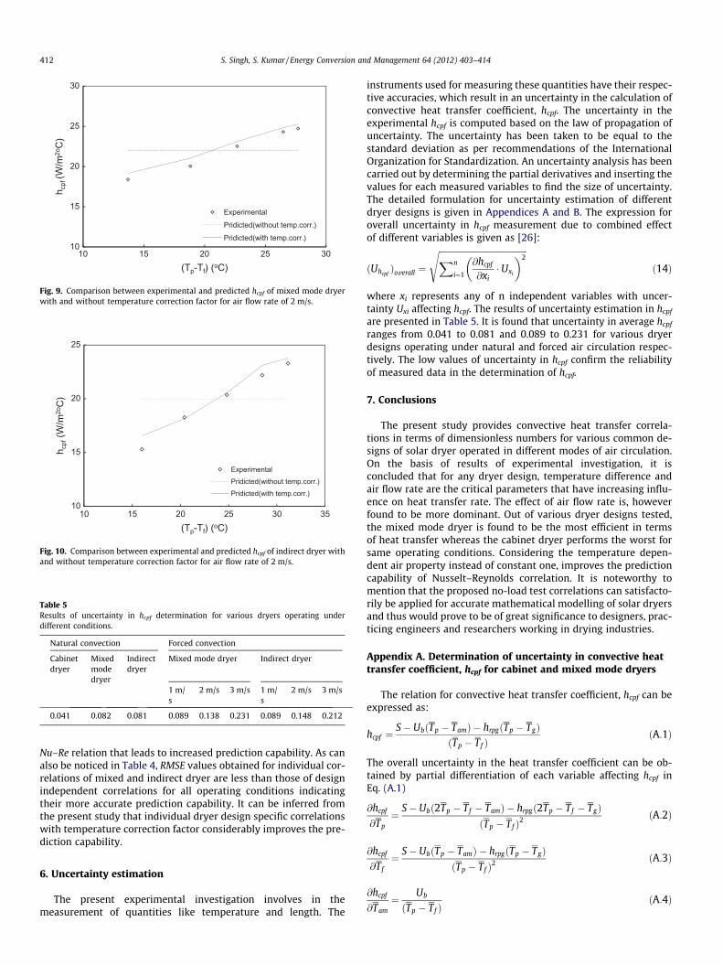
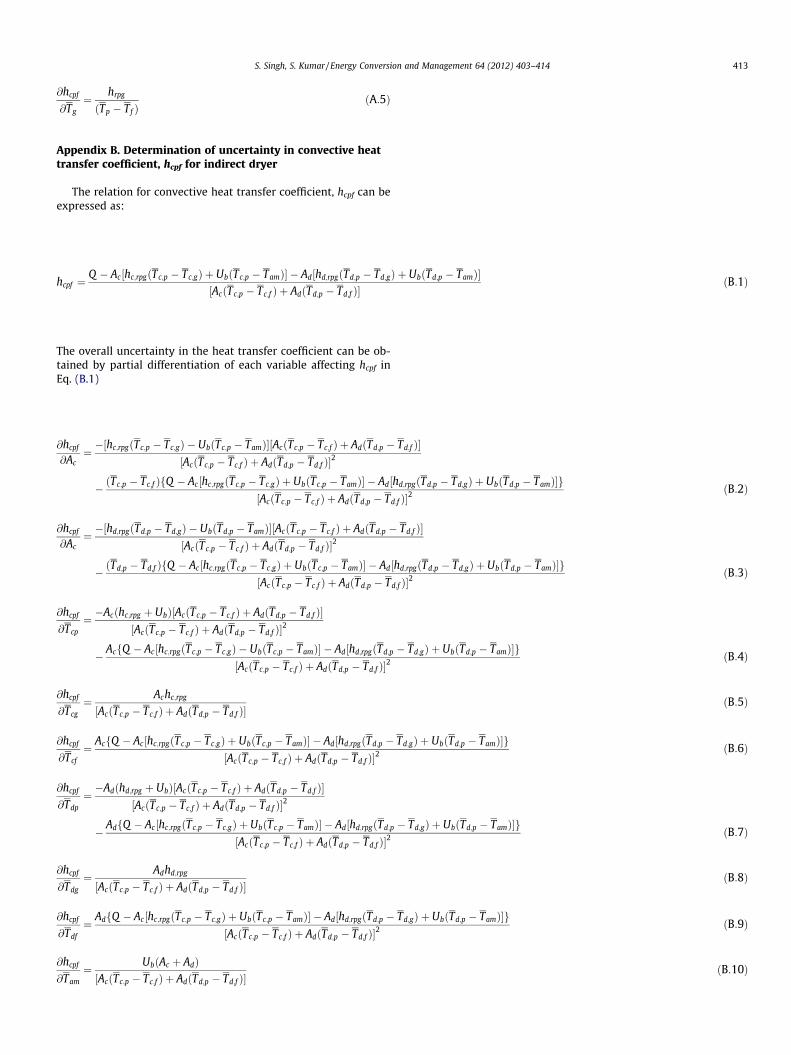
Figs. 9 and 10 represent predicted and experimental hcpf resultsof mixed and indirect dryer respectively for air flow rate of 2 m/s,considering with and without the temperature correction factor.Similar trends in results have also been noticed for other air flowrates of 1 and 3 m/s (results are not shown). It can be seen thatfor both dryer designs, the use of constant air property values inprediction analysis causes a substantial deviation from experimen-tal data whereas a fairly close agreement is obtained when modi-fied Nu–Re relation with temperature correction is used. Thesefindings are confirmed from RMSE error estimation results pre-sented in Table 4. It is found that for the air flow rate range inves-tigated, indirect dryer exhibits respective RMSE values in the rangeof 0.731–1.145 W/m2 �C and 1.696–3.397 W/m2 �C consideringwith and without temperature effect in prediction analysis. Thefigures for mixed mode dryer, the values are found to vary from0.706 to 0.928 W/m2 �C and 2.050 to 3.437 W/m2 �C. The signifi-cantly lower RMSE value obtained with temperature correctionfactor in both dryer designs indicates the suitability of modified
10
15
20
25
30
10 15 20 25 30
h cpf
(W/m
2oC
)
(Tp-Tf) (oC)
Experimental
Pridicted(without temp.corr.)
Pridicted(with temp.corr.)
Fig. 9. Comparison between experimental and predicted hcpf of mixed mode dryerwith and without temperature correction factor for air flow rate of 2 m/s.
10
15
20
25
10 15 20 25 30 35
h cpf
(W/m
2oC
)
(Tp-Tf) (oC)
ExperimentalPridicted(without temp.corr.)Pridicted(with temp.corr.)
Fig. 10. Comparison between experimental and predicted hcpf of indirect dryer withand without temperature correction factor for air flow rate of 2 m/s.
Table 5Results of uncertainty in hcpf determination for various dryers operating underdifferent conditions.
Natural convection Forced convection
Cabinetdryer
Mixedmodedryer
Indirectdryer
Mixed mode dryer Indirect dryer
1 m/s
2 m/s 3 m/s 1 m/s
2 m/s 3 m/s
0.041 0.082 0.081 0.089 0.138 0.231 0.089 0.148 0.212
412 S. Singh, S. Kumar / Energy Conversion and Management 64 (2012) 403–414
Nu–Re relation that leads to increased prediction capability. As canalso be noticed in Table 4, RMSE values obtained for individual cor-relations of mixed and indirect dryer are less than those of designindependent correlations for all operating conditions indicatingtheir more accurate prediction capability. It can be inferred fromthe present study that individual dryer design specific correlationswith temperature correction factor considerably improves the pre-diction capability.
6. Uncertainty estimation
The present experimental investigation involves in themeasurement of quantities like temperature and length. The
instruments used for measuring these quantities have their respec-tive accuracies, which result in an uncertainty in the calculation ofconvective heat transfer coefficient, hcpf. The uncertainty in theexperimental hcpf is computed based on the law of propagation ofuncertainty. The uncertainty has been taken to be equal to thestandard deviation as per recommendations of the InternationalOrganization for Standardization. An uncertainty analysis has beencarried out by determining the partial derivatives and inserting thevalues for each measured variables to find the size of uncertainty.The detailed formulation for uncertainty estimation of differentdryer designs is given in Appendices A and B. The expression foroverall uncertainty in hcpf measurement due to combined effectof different variables is given as [26]:
ðUhcpfÞoverall ¼
ffiffiffiffiffiffiffiffiffiffiffiffiffiffiffiffiffiffiffiffiffiffiffiffiffiffiffiffiffiffiffiffiffiffiffiffiffiffiffiffiffiffiXn
i¼1
@hcpf
@xi� Uxi
� �2s
ð14Þ
where xi represents any of n independent variables with uncer-tainty Uxi affecting hcpf. The results of uncertainty estimation in hcpf
are presented in Table 5. It is found that uncertainty in average hcpf
ranges from 0.041 to 0.081 and 0.089 to 0.231 for various dryerdesigns operating under natural and forced air circulation respec-tively. The low values of uncertainty in hcpf confirm the reliabilityof measured data in the determination of hcpf.
7. Conclusions
The present study provides convective heat transfer correla-tions in terms of dimensionless numbers for various common de-signs of solar dryer operated in different modes of air circulation.On the basis of results of experimental investigation, it isconcluded that for any dryer design, temperature difference andair flow rate are the critical parameters that have increasing influ-ence on heat transfer rate. The effect of air flow rate is, howeverfound to be more dominant. Out of various dryer designs tested,the mixed mode dryer is found to be the most efficient in termsof heat transfer whereas the cabinet dryer performs the worst forsame operating conditions. Considering the temperature depen-dent air property instead of constant one, improves the predictioncapability of Nusselt–Reynolds correlation. It is noteworthy tomention that the proposed no-load test correlations can satisfacto-rily be applied for accurate mathematical modelling of solar dryersand thus would prove to be of great significance to designers, prac-ticing engineers and researchers working in drying industries.
Appendix A. Determination of uncertainty in convective heattransfer coefficient, hcpf for cabinet and mixed mode dryers
The relation for convective heat transfer coefficient, hcpf can beexpressed as:
hcpf ¼S� UbðTp � TamÞ � hrpgðTp � TgÞ
ðTp � Tf ÞðA:1Þ
The overall uncertainty in the heat transfer coefficient can be ob-tained by partial differentiation of each variable affecting hcpf inEq. (A.1)
@hcpf
@Tp¼ S� Ubð2Tp � Tf � TamÞ � hrpgð2Tp � Tf � TgÞ
ðTp � Tf Þ2ðA:2Þ
@hcpf
@Tf
¼ S� UbðTp � TamÞ � hrpgðTp � TgÞðTp � Tf Þ2
ðA:3Þ
@hcpf
@Tam¼ Ub
ðTp � Tf ÞðA:4Þ
S. Singh, S. Kumar / Energy Conversion and Management 64 (2012) 403–414 413
@hcpf
@Tg¼ hrpg
ðTp � Tf ÞðA:5Þ
Appendix B. Determination of uncertainty in convective heattransfer coefficient, hcpf for indirect dryer
The relation for convective heat transfer coefficient, hcpf can beexpressed as:
hcpf ¼Q � Ac½hc;rpgðTc;p � Tc;gÞ þ UbðTc;p � TamÞ� � Ad½hd;rpgðTd;p � Td;gÞ þ UbðTd;p � TamÞ�
½AcðTc;p � Tc;f Þ þ AdðTd;p � Td;f Þ�ðB:1Þ
The overall uncertainty in the heat transfer coefficient can be ob-tained by partial differentiation of each variable affecting hcpf inEq. (B.1)
@hcpf
@Ac¼ �½hc;rpgðTc;p � Tc;gÞ � UbðTc;p � TamÞ�½AcðTc;p � Tc;f Þ þ AdðTd;p � Td;f Þ�
½AcðTc;p � Tc;f Þ þ AdðTd;p � Td;f Þ�2
� ðTc;p � Tc;f ÞfQ � Ac½hc;rpgðTc;p � Tc;gÞ þ UbðTc;p � TamÞ� � Ad½hd;rpgðTd;p � Td;gÞ þ UbðTd;p � TamÞ�g½AcðTc;p � Tc;f Þ þ AdðTd;p � Td;f Þ�2
ðB:2Þ
@hcpf
@Ac¼ �½hd;rpgðTd;p � Td;gÞ � UbðTd;p � TamÞ�½AcðTc;p � Tc;f Þ þ AdðTd;p � Td;f Þ�
½AcðTc;p � Tc;f Þ þ AdðTd;p � Td;f Þ�2
� ðTd;p � Td;f ÞfQ � Ac½hc;rpgðTc;p � Tc;gÞ þ UbðTc;p � TamÞ� � Ad½hd;rpgðTd;p � Td;gÞ þ UbðTd;p � TamÞ�g½AcðTc;p � Tc;f Þ þ AdðTd;p � Td;f Þ�2
ðB:3Þ
@hcpf
@Tcp¼ �Acðhc;rpg þ UbÞ½AcðTc;p � Tc;f Þ þ AdðTd;p � Td;f Þ�
½AcðTc;p � Tc;f Þ þ AdðTd;p � Td;f Þ�2
� AcfQ � Ac½hc;rpgðTc;p � Tc;gÞ � UbðTc;p � TamÞ� � Ad½hd;rpgðTd;p � Td;gÞ þ UbðTd;p � TamÞ�g½AcðTc;p � Tc;f Þ þ AdðTd;p � Td;f Þ�2
ðB:4Þ
@hcpf
@Tcg¼ Achc;rpg
½AcðTc;p � Tc;f Þ þ AdðTd;p � Td;f Þ�ðB:5Þ
@hcpf
@Tcf
¼ AcfQ � Ac½hc;rpgðTc;p � Tc;gÞ þ UbðTc;p � TamÞ� � Ad½hd;rpgðTd;p � Td;gÞ þ UbðTd;p � TamÞ�g½AcðTc;p � Tc;f Þ þ AdðTd;p � Td;f Þ�2
ðB:6Þ
@hcpf
@Tdp
¼ �Adðhd;rpg þ UbÞ½AcðTc;p � Tc;f Þ þ AdðTd;p � Td;f Þ�½AcðTc;p � Tc;f Þ þ AdðTd;p � Td;f Þ�2
� AdfQ � Ac½hc;rpgðTc;p � Tc;gÞ þ UbðTc;p � TamÞ� � Ad½hd;rpgðTd;p � Td;gÞ þ UbðTd;p � TamÞ�g½AcðTc;p � Tc;f Þ þ AdðTd;p � Td;f Þ�2
ðB:7Þ
@hcpf
@Tdg
¼ Adhd;rpg
½AcðTc;p � Tc;f Þ þ AdðTd;p � Td;f Þ�ðB:8Þ
@hcpf
@Tdf
¼ AdfQ � Ac½hc;rpgðTc;p � Tc;gÞ þ UbðTc;p � TamÞ� � Ad½hd;rpgðTd;p � Td;gÞ þ UbðTd;p � TamÞ�g½AcðTc;p � Tc;f Þ þ AdðTd;p � Td;f Þ�2
ðB:9Þ
@hcpf
@Tam¼ UbðAc þ AdÞ½AcðTc;p � Tc;f Þ þ AdðTd;p � Td;f Þ�
ðB:10Þ
414 S. Singh, S. Kumar / Energy Conversion and Management 64 (2012) 403–414
References
[1] MOFPI. Ministry of Food Processing Industries, Government of India, NewDelhi. Annual report, 2010–11. <http://www.mofpi.nic.in/images/ar10-11.pdf>[accessed 10.04.12].
[2] Basunia MA, Abe T. Thin layer solar characteristics of rough rice under naturalconvection. J Food Eng 2001;47:295–301.
[3] Ekechukwu O, Norton B. Review of solar-energy drying systems II: an overviewof solar drying technology. Energy Convers Manage 1999;40(6):615–55.
[4] Leon MA, Kumar S, Bhattacharya SC. A comprehensive procedure forperformance evaluation of solar food dryers. Renew Sustain Energy2002;6:367–93.
[5] Sharma VK, Colangelo A, Spagn G. Experimental investigation of different solardryers suitable for fruit and vegetable drying. Energy 1995;6(4):413–24.
[6] Alam A. Agriculture processing and post harvest technology for ensuring foodsecurity. Agric Eng Today 2010;34(3):7–20.
[7] Simate IN. Optimization of mixed mode and indirect mode natural convectionsolar dryers. Renew Energy 2003;28(3):435–53.
[8] Sharma A, Chen C, Nguyen VL. Solar-energy drying systems: a review. RenewSustain Energy Rev 2009;13:1185–210.
[9] Muneer T, Kubie J, Grassie T. Heat transfer: a problem solving approach.London: Taylor and Francis; 2003.
[10] Hegazy AA. Comparative study of the performances of four photovoltaic/thermal solar air collectors. Energy Convers Manage 2000;41:861–81.
[11] Forson FK, Nazha MAA, Rajakaruna H. Experimental and simulation studies ona single pass, double duct solar air heater. Energy Convers Manage2003;44(8):1209–27.
[12] Pakdaman MF, Lashkari A, Tabrizi HB, Hosseini R. Performance evaluation of anatural-convection solar air-heater with a rectangular-finned absorber plate.Energy Convers Manage 2011;52:1215–25.
[13] Goyal RK, Tiwari GN. Performance of a reverse flat plate absorber cabinetdryer: a new concept. Energy Convers Manage 1999;40:385–92.
[14] Jain D, Tiwari GN. Effect of greenhouse on crop drying under natural andforced convection I. Evaluation of convective heat transfer coefficient. EnergyConvers Manage 2004;45:765–83.
[15] Rahman N, Kumar S. Evaluation of convective heat transfer coefficient duringdrying of shrinking bodies. Energy Convers Manage 2006;47(15–16):2591–601.
[16] Garg HP, Kumar R. Studies on semi-cylindrical solar tunnel dryers: thermalperformance of collector. Appl Therm Eng 2000;20(2):115–31.
[17] Montero I, Blanco J, Miranda T, Rojas S, Celma AR. Design, construction andperformance testing of a solar dryer for agro-industrial by-products. EnergyConvers Manage 2010;51(7):1510–21.
[18] Smitabhindu R, Janjai S, Chankong V. Optimization of a solar-assisted dryingsystem for drying bananas. Renew Energy 2008;33:1523–31.
[19] ASHRAE Standard 93-1986. Method of testing to determine the thermalperformance of solar collectors. American Society for Heating, Refrigeratingand Air-conditioning Engineers, Atlanta, USA; 1986.
[20] IS 13429. Solar cooker – box type specification – part 3: test method. Bureau ofIndian Standard, New Delhi, India; 2000.
[21] Duffie JA, Beckman WA. Thermal engineering of thermal processes. NewYork: John Wiley & Sons; 1991.
[22] Zaman MA, Bala BK. Thin layer solar drying of rough rice. Sol Energy1989:167–71.
[23] Holman JP. Heat transfer. New Delhi: Tata McGraw-Hill; 2003.[24] Samdarshi SK, Mullick SC. Analytical equation for the top heat loss factor of a
flat plate collector with double glazing. J Sol Energy Eng 1991;113:117–22.[25] Kothandaraman CP. Fundamentals of heat and mass transfer. New Delhi: New
Age International (P) Publishers; 2009.[26] Nakra BC, Chaudhry KK. Instrumentation, measurement and analysis. New
Delhi: Tata McGraw-Hill; 2004.