Energy Performance of Convective Dryers* · heating of a drying air. ... microwave-assisted ... the...
22
1 Energy Performance of Convective Dryers* T. Kudra CanmetENERGY, Natural Resources Canada, Varennes, QC, Canada J3X 1S6 Running head: Energy performance Correspondence: T. Kudra, CanmetENERGY, 1615 Lionel-Boulet Blvd., Varennes, QC, Canada J3X 1S6; E-mail: [email protected] * Copyright © Her Majesty the Queen in Right of Canada, as represented by the Minister of Natural Resources, 2012. ABSTRACT Following the background information to energy efficiency measures this paper presents the methodology and the calculation results on energy performance of several industrial dryers quantified in terms of the specific energy consumption and compared to the results obtained from the Baker and McKenzie’s adiabatic dryer model for convective dryers. Examples of performance assessment are given for indirectly heated spouted bed dryer with inert particles and spray dryer with integrated fluidized bed. Because the energy performance determination is based on temperature and humidity of the ambient and exhaust air, the calculation method is also given for gas-fired direct dryers represented by a natural-gas heated pneumatic dryer where combustion air and generated water vapor have to be accounted for. Keywords: Convective dryers; Drying; Energy efficiency; Fast spouted bed; Hybrid dryer; Specific energy consumption; Pneumatic dryer. INTRODUCTION The energy cost in terms of heat represents a significant fraction of the total drying cost especially in the case of the most popular convective dryers. Even though almost 100% of the thermal energy contained in the fuel is passed into drying air in direct dryers in contrast to
Transcript of Energy Performance of Convective Dryers* · heating of a drying air. ... microwave-assisted ... the...

1
Energy Performance of Convective Dryers*
T. Kudra
CanmetENERGY, Natural Resources Canada, Varennes, QC, Canada J3X 1S6
Running head: Energy performance
Correspondence: T. Kudra, CanmetENERGY, 1615 Lionel-Boulet Blvd., Varennes, QC,
Canada J3X 1S6; E-mail: [email protected]
* Copyright © Her Majesty the Queen in Right of Canada, as represented by the Minister of
Natural Resources, 2012.
ABSTRACT
Following the background information to energy efficiency measures this paper presents the
methodology and the calculation results on energy performance of several industrial dryers
quantified in terms of the specific energy consumption and compared to the results obtained from
the Baker and McKenzie’s adiabatic dryer model for convective dryers. Examples of
performance assessment are given for indirectly heated spouted bed dryer with inert particles and
spray dryer with integrated fluidized bed. Because the energy performance determination is
based on temperature and humidity of the ambient and exhaust air, the calculation method is also
given for gas-fired direct dryers represented by a natural-gas heated pneumatic dryer where
combustion air and generated water vapor have to be accounted for.
Keywords: Convective dryers; Drying; Energy efficiency; Fast spouted bed; Hybrid dryer;
Specific energy consumption; Pneumatic dryer.
INTRODUCTION
The energy cost in terms of heat represents a significant fraction of the total drying cost
especially in the case of the most popular convective dryers. Even though almost 100% of the
thermal energy contained in the fuel is passed into drying air in direct dryers in contrast to
2
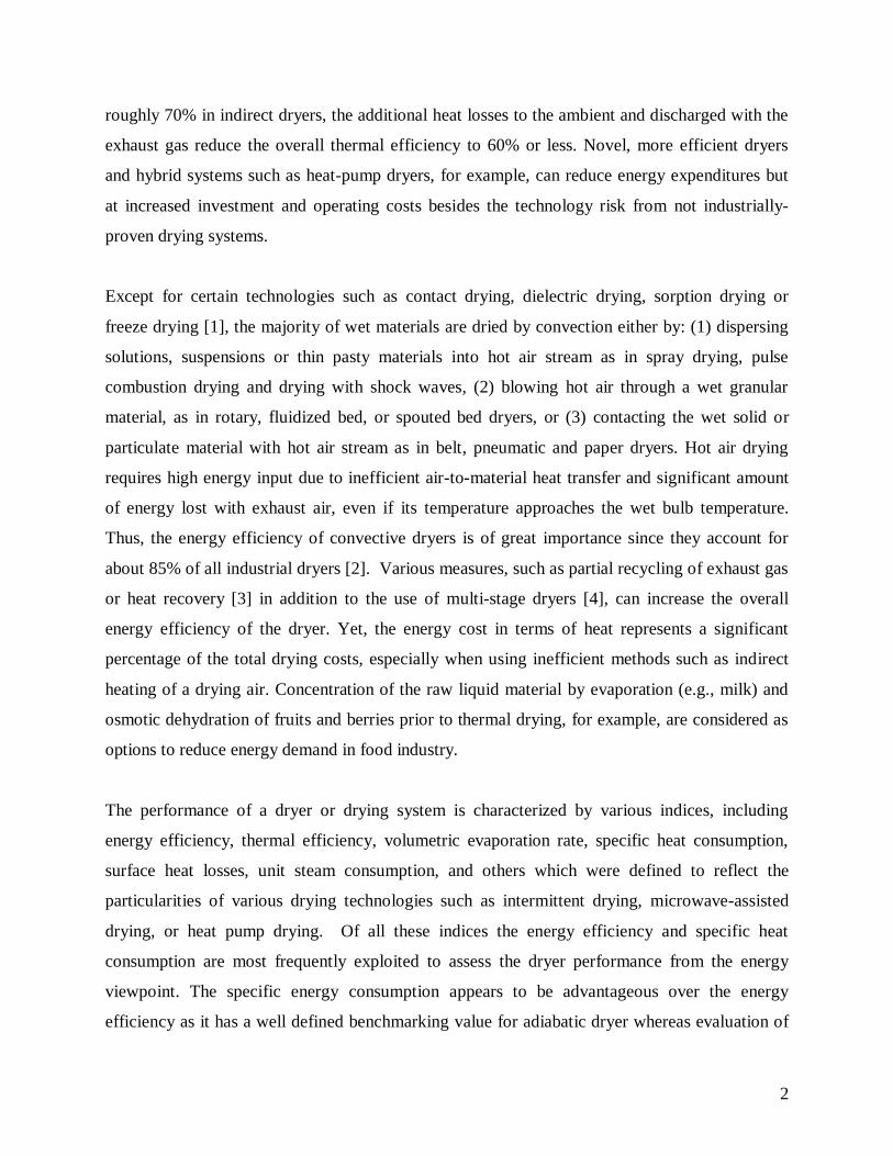
roughly 70% in indirect dryers, the additional heat losses to the ambient and discharged with the
exhaust gas reduce the overall thermal efficiency to 60% or less. Novel, more efficient dryers
and hybrid systems such as heat-pump dryers, for example, can reduce energy expenditures but
at increased investment and operating costs besides the technology risk from not industrially-
proven drying systems.
Except for certain technologies such as contact drying, dielectric drying, sorption drying or
freeze drying [1], the majority of wet materials are dried by convection either by: (1) dispersing
solutions, suspensions or thin pasty materials into hot air stream as in spray drying, pulse
combustion drying and drying with shock waves, (2) blowing hot air through a wet granular
material, as in rotary, fluidized bed, or spouted bed dryers, or (3) contacting the wet solid or
particulate material with hot air stream as in belt, pneumatic and paper dryers. Hot air drying
requires high energy input due to inefficient air-to-material heat transfer and significant amount
of energy lost with exhaust air, even if its temperature approaches the wet bulb temperature.
Thus, the energy efficiency of convective dryers is of great importance since they account for
about 85% of all industrial dryers [2]. Various measures, such as partial recycling of exhaust gas
or heat recovery [3] in addition to the use of multi-stage dryers [4], can increase the overall
energy efficiency of the dryer. Yet, the energy cost in terms of heat represents a significant
percentage of the total drying costs, especially when using inefficient methods such as indirect
heating of a drying air. Concentration of the raw liquid material by evaporation (e.g., milk) and
osmotic dehydration of fruits and berries prior to thermal drying, for example, are considered as
options to reduce energy demand in food industry.
The performance of a dryer or drying system is characterized by various indices, including
energy efficiency, thermal efficiency, volumetric evaporation rate, specific heat consumption,
surface heat losses, unit steam consumption, and others which were defined to reflect the
particularities of various drying technologies such as intermittent drying, microwave-assisted
drying, or heat pump drying. Of all these indices the energy efficiency and specific heat
consumption are most frequently exploited to assess the dryer performance from the energy
viewpoint. The specific energy consumption appears to be advantageous over the energy
efficiency as it has a well defined benchmarking value for adiabatic dryer whereas evaluation of

3
the dryer performance through the energy efficiency requires the knowledge of the maximum
energy efficiency which depends on the material properties and drying conditions.
A great help to the dryer users in process analysis and simulation as well as dryer selection,
troubleshooting, and information search could be the commercially available and in-house
developed software packages reviewed by Kemp [5]. Regarding energy issues, of particular
interest in examining the energy performance of industrial dryers under operation appears to be
the Excel-VBA tool developed to fill the gap in computer-based tools. It allows calculation of the
energy use in industrial dryers, evaluation of the potential for energy savings, and analysis of the
options for reducing energy consumption [6]. In this tool, the calculations of real and theoretical
energy efficiency are based on the concept of the excess specific energy consumption proposed
by Baker and McKenzie [7] for indirectly heated spray dryers, and extended to fluidized bed
dryers. However, aforementioned paper [6] focuses only on the background information on
energy performance determination, outlines the general architecture of the calculation tool, and
presents an example of input data and calculation results. Therefore, this paper aims at providing
the potential users of this tool with some examples of energy performance calculations for
representative single- and two-stage convective dryers with direct and indirect heating as well as
highlights some specific conditions to be accounted for such as flawless determination of exhaust
air temperature or negative temperature of ambient air.
BASIC MEASURES OF ENERGY PERFORMANCE
Energy/Thermal Efficiency
The widely used energy efficiency (η) relates the energy used for moisture evaporation at the
material feed temperature (Eev) to the total energy supplied to the dryer (Et)
t
evEE
(1)
Details regarding Eev and Et calculations can be found in the recent book on food dehydration
[8]. Considering only the energy used to heat drying air which enters a single-pass theoretical
convective dryer, Equation 1 can be rewritten as
ao
ao
ai
ai
ai
t
IIYYH
IIYYH
IIWH
(2)

4
The specific air consumption (W*) is given by mass of air required to evaporate 1 kg of water [9]
aoev
g
YY1
WW
W
(3)
A theoretical dryer is defined as a dryer with no heat spent for heating the material and
transportation equipment, heat is not supplied to the internal heater, heat is not lost to the
ambient atmosphere, and the inlet material temperature is 0°C. Thus, the energy efficiency of a
real dryer can be determined from the following relation:
lao* QIIW
H
(4)
or expressed in terms of the theoretical dryer
HQ1
1l
t
(5)
where ∑Ql represents the overall heat losses from the dryer.
For low-humidity and low-temperature convective drying, the energy efficiency can be
approximated by thermal efficiency (ηT) that is based on the inlet air temperature (Ti), the outlet
air temperature (To) and the ambient temperature (Ta)
ai
oiT TT
TT
(6)
The thermal (energy) efficiency does not indicate how good the dryer is unless it is compared with
the maximum thermal efficiency (ηT, max) which is attained when the outlet air temperature equals
either the wet bulb temperature (TWB) or the negligibly lower [10, 11] adiabatic saturation
temperature (TAS)
ai
ASi
ai
WBimax,T TT
TTTT
TT
(7)
From Eq. 1 it follows that the maximum energy efficiency exists when the outlet air is saturated
with water vapor (Yosat) that can be attained for a given evaporation rate when the air flow is
minimal, yet securing both heat and hydrodynamic requirements. Thus,

5
ao
asato
max IIYYH
(8)
Complete saturation of exhaust air never occurs in practice because the exhaust gas temperature
should be kept below the saturation temperature (typically by 10°C [7]) to avoid condensation in
exhaust ducts and cyclone/filter systems.
When drying hygroscopic materials, the relative humidity of the air stream at any point in the dryer
should be lower than the equilibrium relative humidity at this point. Thus, for such materials the
maximum energy efficiency is restricted not by the exhaust air saturation but by the equilibrium
humidity (Yoeq) determined from sorption isotherms [8]
ao
aeqo
max IIYYH
(9)
Specific Energy Consumption
An alternative measure of dryer efficiency is the specific energy consumption (Es), which is
defined as the heat input to the dryer (Qh) per unit mass of evaporated water (Wev) [12]. Because
for convective dryers the heat input is given as power supplied to the heater then
PFS
h
ev
hs XXF
QWQE
(10)
where FS is the solids-based material feed rate, and XF and XP represent the moisture contents (dry
basis) in the feed and the product, respectively. Figure 1 presents the schematics of a single-stage
indirectly-heated convective dryer in which the specific nomenclature used by Baker and co-
workers has been retained to facilitate future analysis of the source publications.
Insert Figure 1 here
In industrial practice, the feed flow rate (F) is given in kg/h of the material fed to the dryer and the
feed moisture content is given in mass percent of solids (XS). Thus, the rate of water evaporation
can be calculated from the following relationship:
F
PFev X1
XXFW
(11)

6
where
S
SF X
X100X
(12)
Baker and McKenzie [7] derived the following expression for the specific energy consumption of a
theoretical dryer, which indicates that the specific energy consumption of an unspecified indirectly-
heated convective dryer depends on the temperature and humidity of the outlet air and the heat loss
ao
aloref
ao
alogs YY
Y1/YH
YYT1/T
cE (13)
where ΔHref is the latent heat of evaporation at 0°C, taken as the reference temperature, cg is the heat
capacity of air (gas), and ηl is the thermal loss factor of the dryer.
The thermal loss factor in Eq. 13 is defined as
ig
ll IW
Q (14)
where Wg is the dry basis air-flow rate.
For an adiabatic dryer ηl = 0 so Equation 13 reduces to
refao
aoga,s H
YYTT
cE
(15)
where Es.a is the specific energy consumption of an ideal adiabatic dryer under given operating
conditions.
A difference between specific energy consumption of the real and theoretical dryers operated at the
same exhaust air temperature and humidity gives the excess specific energy consumption, which is
a measure of the wasted energy due to heat losses and other inefficiencies [7]
a,ssx,s EEE (16)
The concept of using the specific energy consumption to evaluate the performance of indirectly-
heated spray dryers presented by Baker and McKenzie [7] and extended to fluidized bed dryers [12-
14], was successfully validated for other single-stage and combined convective dryers during the
development of the aforementioned calculation tool [6]. Because in that paper only the input data
and results of calculations had been presented, details of energy performance evaluation for
representative dryers are given in the subsequent paragraph.

7
ENERGY PERFORMANCE EVALUATION FOR SELECTED DRYERS
Fast Spouted Bed Dryer with Inert Particles.
The principle behind drying of liquid materials on inert solid particles (also called carriers as
they carry on the material during drying) lies in atomizing the liquid feed such as a solution,
suspension or soft paste which then coats in a thin layer the surface of inert particles. These
particles are “fluidized” either by the sole hydrodynamic impact of the hot air stream, or in
combination with mechanical impact induced by mixers, vibrators, screw conveyors and others.
The liquid coat on the particle surface dries by convective heat transfer from hot air, and contact
heat transfer due to sensible heat accumulated in the inert particles when they pass the hot air
zone. It should be noted that although heat transfer by conduction complements convective heat
transfer, this type of a dryer falls into a category of convective dryers as the thermal energy for
water evaporation is supplied exclusively by the hot air stream.
Because of water evaporation during drying, the liquid coat on the particle surface turns
eventually into a brittle shell which is then chipped off from the particle surface, powdered by
particle-to-particle and particle-to-wall collisions and discharged from the drying chamber with
the exhaust air. Of various configurations of dryers with inert carriers [1] the most frequently
examined is the jet-spouted bed with inert particles. Here, the high-velocity stream of hot air (the
jet) brings the solid particles into the spout-like motion, practically in the entire volume of the
conical or conical-cylindrical drying chamber.
The laboratory (V=0.035 m3) jet-spouted bed dryer with inert carriers and its pilot-scale variant
(V=0.66 m3) termed the fast spouted bed (FSB) dryer with inert carriers (Fig. 2) [15] have
thoroughly been laboratory and industrially tested by CanmetENERGY (Varennes, QC, Canada)
for a variety of products including vegetable starch, egg yolk, pine and alfalfa extracts, soups
made from cooked and homogenized lentils, green peas and chicken pea, and the like. To reduce
heat losses the pilot dryer, heater and ducts have been insulated with a 10-cm thick water-
repellent mineral wool and covered with the 3.2-mm thick stainless steel sheath. The laboratory
8
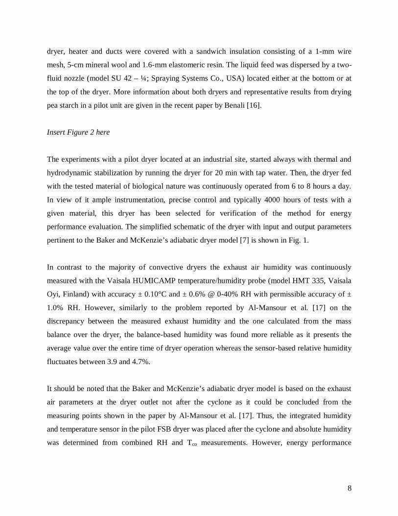
dryer, heater and ducts were covered with a sandwich insulation consisting of a 1-mm wire
mesh, 5-cm mineral wool and 1.6-mm elastomeric resin. The liquid feed was dispersed by a two-
fluid nozzle (model SU 42 – ¼; Spraying Systems Co., USA) located either at the bottom or at
the top of the dryer. More information about both dryers and representative results from drying
pea starch in a pilot unit are given in the recent paper by Benali [16].
Insert Figure 2 here
The experiments with a pilot dryer located at an industrial site, started always with thermal and
hydrodynamic stabilization by running the dryer for 20 min with tap water. Then, the dryer fed
with the tested material of biological nature was continuously operated from 6 to 8 hours a day.
In view of it ample instrumentation, precise control and typically 4000 hours of tests with a
given material, this dryer has been selected for verification of the method for energy
performance evaluation. The simplified schematic of the dryer with input and output parameters
pertinent to the Baker and McKenzie’s adiabatic dryer model [7] is shown in Fig. 1.
In contrast to the majority of convective dryers the exhaust air humidity was continuously
measured with the Vaisala HUMICAMP temperature/humidity probe (model HMT 335, Vaisala
Oyi, Finland) with accuracy ± 0.10°C and ± 0.6% @ 0-40% RH with permissible accuracy of ±
1.0% RH. However, similarly to the problem reported by Al-Mansour et al. [17] on the
discrepancy between the measured exhaust humidity and the one calculated from the mass
balance over the dryer, the balance-based humidity was found more reliable as it presents the
average value over the entire time of dryer operation whereas the sensor-based relative humidity
fluctuates between 3.9 and 4.7%.
It should be noted that the Baker and McKenzie’s adiabatic dryer model is based on the exhaust
air parameters at the dryer outlet not after the cyclone as it could be concluded from the
measuring points shown in the paper by Al-Mansour et al. [17]. Thus, the integrated humidity
and temperature sensor in the pilot FSB dryer was placed after the cyclone and absolute humidity
was determined from combined RH and Tco measurements. However, energy performance

9
calculations were based on the outlet air temperature (To) that was measured close to the dryer
outlet albeit the temperature difference was only 1.5°C.
Insert Table 1 and Table 2 here
The characteristics of the dryer and operating parameters over 6-hour run are given in Table 1
whereas results of calculations are compiled in Table 2.
Interestingly, the FSB dryer is fairly energy efficient as indicated by the excess specific energy
consumption and also by thermal efficiency of 52%, even though the high-velocity air stream is
needed to spout the inert particles.
Spray Dryer with Integrated Fluid Bed The multi-stage dryers represent a combination of several single-stage dryers such as a spray
dryer with external fluid bed that can be considered as separated dryers, or a hybrid configuration
such as a spray dryer with integrated fluid bed where it is not possible to break up such a dryer
for the calculation purpose.
Insert Figure 3 here
Figure 3 presents the schematics of a hybrid dryer consisting of the conventional spray dryer and
a built-in fluidized bed dryer. In this particular configuration designed for drying heat-sensitive
and hygroscopic biomaterials, the co-current spray dryer is fed from the top by two high-pressure
nozzles which disperse the liquid feed into fine droplets. To prevent material deterioration both
nozzles are cooled by two ambient air streams injected into the nozzles casing. The liquid sprays
generated by the nozzles are then dried by the co-currently flowing primary hot air stream heated
to the required temperature in a steam-air heat exchanger. The partially dry material falls into the
cylindrical fluid bed dryer supplied from the bottom with the secondary hot air stream heated
indirectly in a steam-air heat exchanger. In case of excessive ambient air humidity, the air stream
injected to the fluid bed dryer is dehumidified in a heat exchanger by cooling with cold water.
The fraction of dry fine particles (~ 0.1 mm) is entrained with exhaust air to the cyclone whereas
the main part of the material is discharged from the fluidized bed through an air-lock. In the

10
majority of hygroscopic materials exemplified by the specialty carbohydrates the product has to
be obtained in the form of granules with size varying from 1 to 2 mm. The granulation takes
place in the fluidized bed of this combined dryer by adjusting air velocity, temperature and
baffles/partitions in the fluidized bed. In such a situation the powdery fraction of the material
collected in the cyclone is returned back to the dryer through the pneumatic transport in a
dehumidified and moderately heated air. Thus, the granular product material is discharged from
the fluidized bed component of this combined dryer. To reduce heat losses all parts of the dryer
have been insulated with a 1-cm mineral wool and covered with an aluminum foil.
Regarding the condition to be satisfied for the presented method of energy performance
evaluation, the drying air (inlet air) comes from two hot air streams, namely from the primary air
supplied to the spray dryer and from the secondary air supplied to the integrated fluid bed dryer.
Thus, the exhaust air is the sum of both air streams and the air used to cool the nozzles.
Regarding the heat input the cooling air streams can be neglected as they constitute only 6% of
the drying air but accounted in the exhaust air humidity. Also, as reported by the dryer operator,
the air stream for pneumatic transport of particles back to the hybrid dryer is negligible in this
configuration. Therefore, this combined dryer can be simplified to a single-stage convective
dryer represented by Fig. 1 where the heat input to the dryer is given as the sum of the heat input
to the spray dryer and fluid bed dryer.
The characteristics of the dryer and results of calculations are given in Tables 3 and 4,
respectively.
Insert Table 3 here
Insert Table 4 here
Because of process variability, the dryer designed for operation with two nozzles can be fed only
through one nozzle at the same air flow rates. However, in this case the energy performance
drops dramatically as not entire dryer volume and all air stream are fully utilized. It is
demonstrated through much higher specific energy consumption (c.f., Table 4) and reduced
thermal efficiency, which drops from 28.6% when the feed is dispersed by two nozzles to 26%

11
for the one-nozzle feed. Such an effect could be exploited to monitor the operation of the dryer
with a multi-nozzle feed through the soft sensor control based on the appropriate software if the
outlet air humidity is reliably measured.
Gas-Fired Pneumatic Dryer.
Regarding the mode of heat transfer, convective dryers belong to the group of direct dryers
because heat for water evaporation is transferred by direct contact of the dried material with a
stream of hot gas such as air, carbon dioxide or nitrogen, superheated steam, or flue gases from
combustion of fossil fuels. Commonly, however, direct dryers are perceived as convective dryers
where heat is usually supplied by a mixture of air and products of fuel combustion. To avoid
ambiguity, such dryers are referred to as direct-fired dryers or gas-fired dryers, if natural gas is
combusted in the burner.
Natural gas (NG) is a hydrocarbon mixture consisting primarily of methane (95.53-97.3%) and
ethane (2.06 – 2.1%) with admixtures of nitrogen, carbon dioxide, hydrogen, sulfur compounds in
various concentration depending on the gas source. Natural gas from Canadian sources is
practically free from sulfur compounds so it is the most commonly used in gas-fired industrial
dryers in agri-food industry. The limiting factor in the use of natural gas in drying is relatively
high amount of water vapor generated during combustion, which reduces the moisture holding
capacity of a gas phase and may limit drying of hygroscopic products.
The combustion of methane being the main component of natural gas takes place according the
following exothermal reaction:
QOH2COO2CH 2224 (17)
Stoichiometric combustion requires 9.5 m3 of air per 1 m3 of methane. The water vapor generated
due to combustion of 1 m3 of natural gas is 2 m3, which referred to 10.5 m3 of combustion products
gives the water vapor concentration of 19% vol. In terms of mass calculations, 1 kg of methane
requires 16.5 kg of air for stoichiometric combustion which generates 2.136 kg of water. The real
concentration of water vapor in flue gasses is usually lower (~ 18% vol.) because excess air is

12
needed for complete combustion of natural gas. Since the flame temperature for stoichiometric
combustion of NG reaches 2770°C the flue gases should be diluted with ambient air to reduce the
drying gas temperature and provide sufficient air flow to satisfy hydrodynamic requirements.
Therefore, the mixing chamber should follow the gas-fired combustor although in the majority of
cases both components are combined into a combustion system depicted in Figure 4.
Insert Figure 4 here
Regarding the Baker and McKenzie’s adiabatic dryer model and the methodology for specific
energy calculations which leads to excess specific energy consumption given by Eq. 16, the crucial
is the additional water vapor generated during combustion of natural gas (or other fossil fuel such as
butane or propane) and the combustion air. Accepting the ideogram shown in Figure 1, the mass
flow rate of ambient air should be a sum of flow rates of drying air and air needed for complete
combustion (stoichiometric and excess air). The water vapor generated in the combustion process
increases the outlet gas humidity but this additional humidity does not result from drying so
basically it does not affect the outlet gas temperature and, therefore, it can be considered as an inert
gas. However, the combustion air complements the drying air in the outlet gas so the outlet
humidity should be computed as a mass of water evaporated in the dryer over the combined mass of
drying air, excess air and combustion products (N2 and CO2).
The industrial dryer under evaluation is a single-pass pneumatic dryer of 0.83 m in diameter and a
15 m high vertical column through which a drying gas is drafted by the exhaust fan. The dryer is
fitted with a duct-type gas burner placed in a combustion chamber that is fed with natural gas and
combustion air taken from the ambient. The flue gasses from the burner are mixed with the main
stream of an ambient air to lower the drying gas temperature to the required one. Because of
hydrodynamic requirements for pneumatic transport of dispersed material, the drying air flow rate is
fairly constant so the inlet gas temperature is controlled by the NG flow rate. The material to be
dried is received from the centrifuge as the wet cake, stored in a surge bin with a sweeper arm and
then transported by a variable speed screw conveyor to the hammer mill located at the feed section
of the dryer. The dry material entrained with exhaust gas is separated in two serial cyclones. The
oversize particles (> 0.22 mm) collected in the first cyclone are disintegrated in the pin mill. To

13
reduce heat losses, the burner and the dryer are covered with a 5-cm thermally-resistant solid
insulation. Table 5 presents the operating characteristics of the dryer whereas the results of
calculations are given in Table 6.
Insert Table 5 here
Insert Table 6 here
CONCLUDING REMARKS
1. The Baker and McKenzie’s (B-McK) adiabatic dryer model developed primarily for single-
stage indirect spray dryer can successfully be used for energy performance of various convective
dryers in both single-stage and combined (multi-stage) configurations where drying air passes
each drying stage. Otherwise, the combined dryer exemplified by the spray dryer with external
fluid bed dryer should be considered as a combination of separate dryers.
2. The B-McK model can be used for direct dryers if combustion water is accounted for.
3. The B-McK model allows detection of faulty operation of the dryer such as clogged nozzle in
the multi-nozzle feeding system as the specific energy consumption increases dramatically.
NOMENCLATURE
c Heat capacity, kJ/(kg K)
d. b. Dry basis
E Energy, J
Es Specific energy consumption, kJ/kg H2O
Es, a Specific energy consumption of adiabatic dryer, kJ/kg H2O
Es, x Excess specific energy consumption, kJ/kg H2O
F Feed rate, kg/h
FS Feed rate (dry basis), kg/s
FSB Fast spouted bed

14
HHV Higher heating value, MJ/m3
ΔH Latent heat of vaporization, kJ/kg
I Enthalpy, kJ/kg
NG Natural gas
ΣQl Heat losses, kJ/kg H2O
Q Heat rate, kJ/s
RH Air relative humidity, %
T Temperature, K (°C)
V Volume, m3
w.b. Wet basis
W* Specific air consumption, kg air/kg H2O
W Flow rate, kg/s
X Material moisture content (d. b.), kg H2O/kg dry material
Y Absolute air humidity, kg H2O/kg dry air
η Energy efficiency, -
ηl Thermal loss factor, -
ηT Thermal efficiency, -
Subscripts
a Ambient
AS Adiabatic saturation
c Cyclone
ev Evaporation

15
f Flue gases
F Feed
g Gas (air)
h Heater
i Inlet
l Losses
max Maximum
NG Natural gas
o Outlet
P Product
ref Reference
S Solids
t Total
T Thermal
w Water
WB Wet bulb
Superscripts
c Combustion
eq Equilibrium
t Theoretical
sat Saturation

16
ACKNOWLEDGMENTS
Constructive comments of Prof. C. G. J. Baker from Kuwait University are greatly appreciated.
REFERENCES
1. Kudra, T.; Mujumdar, A.S. Advanced Drying Technologies, 2nd edition; CRC Press; Boca
Raton, FL, 2009.
2. Devahastin, S. (Ed.) Mujumdar’s Guide to Industrial Drying; EXERGEX Corporation;
Montreal, Canada, 2000.
3. Bahu, R. E.; Baker, C. G. J.; Reay, D. Energy balances on industrial dryers – a route to fuel
conservation. Journal of Separation Process Technology 1983, 4 (4), 23-28.
4. Masters, K. Spray Drying in Practice. SprayDryerConsult International ApS; Charlottenlund,
Denmark; 2002, p. 29, 82.
5. Kemp, I. C. Drying software: past, present and future. Drying Technology 2007, 25 (7), 1249-
1263.
6. Kudra, T.; Platon, R.; Navarri P. Excel-based tool to analyze the energy performance of
convective dryers. Drying Technology 2009, 27 (12), 1302-1308.
7. Baker, C. G. J.; McKenzie, K. A. Energy consumption of industrial spray dryers. Drying
Technology 2005, 23 (1&2), 365-386.
8. Kudra, T. Energy aspects in food dehydration. In Advances in Food Dehydration; Ratti, C.,
Ed.; CRC Press: Boca Raton, 2009, pp. 423-445.
9. Strumillo, C.; Kudra, T. Drying: Principles, Applications and Design. Gordon and Breach
Science Publishers; NY. 1986, p.448.

17
10. Pakowski, Z. 2001. dryPak 2000LE: Psychrometric and Drying Computations. OMNIKON
Ltd, Lodz, Poland.
11. Bond, J-F. 2002. Visual Metrix. Drying Doctor, Inc., Verdun, QC, Canada.
12. Baker, C. G. J. Predicting the energy consumption of continuous well-mixed fluidized bed
dryers from drying kinetic data. Drying Technology 1999, 17 (7&8), 1533-1555.
13. Baker, C. G. J.; Khan, A. R.; Ali, Y. I.; Damyar, K. Simulation of plug flow fluidized bed
dryers. Chemical Engineering and Processing 2006, 45, 641-651.
14. Baker, C. G. J.; Al-Adwani, H. H. An evaluation of factors influencing the energy-efficient
operation of well-mixed fluidized bed dryers. Drying Technology 2007, 25 (2), 311-318.
15. Benali, M.; Amazouz, M. Apparatus for producing powder from biomaterials. US Patent No
699 3856. 2006.
16. Benali, M. Drying of yellow pea starch on inert carriers: drying kinetics, moisture diffusivity,
and product quality. Journal of Food Engineering 2012 110, 337-344.
17. Al-Mansour, H. E.; Al-Busairi, B. H.; Baker, C. G. J. Energy consumption of a pilot-scale
spray dryer. Drying Technology 2011, 29 (16), 1901-1910.
Figure captions
Figure 1. Representation of the convective dryer analyzed by the Baker and McKenzie model.
Figure 2. Fast spouted bed dryer with inert particles.
Figure 3. Spray dryer with integrated fluidized bed.
Figure 4. Ideogram of the combustion system.

18
Table 1.
Dryer characteristics and operating parameters for pilot-scale fast spouted bed dryer with inert
carriers.
Material Fermented whey proteins
Feed characteristics
- Mass flow rate of liquid feed
- Solids content / Moisture content
- Temperature
120 kg/h
15-16% w/w / 5.45 kg/kg d.b.*
30.6-34.2°C
Product
- Moisture content
0.0287-0.0307 kg/kg d.b. (2.97 kg/kg d.b.)*
Drying air
- Mass flow rate
- Ambient humidity
- Ambient temperature
- Inlet air temperature
- Outlet air temperature (dryer)
- Outlet air temperature (cyclone)
- Outlet air relative humidity (cyclone)
- Outlet air absolute humidity (mass balance)
3221.1 kg/h
66.0-68.1% (67% at 22.0°C)*
21.7 – 22.8°C (22.0°C)*
190°C
102.5°C
101.0°C
3.9-4.7% at 101.0°C
0.04164 kg/kg
Inert particles 8 kg of 5-mm Teflon beads
* Value taken for calculations in the case of fluctuating parameter
Table 2.
Energy performance - results of calculations for FSB dryer.
Wev, kg/h (Yo-Ya), kg/kg Es, kJ/kg H2O Es, a, kJ/kg H2O
100.8 0.03042 5601.73 5161.63

19
Table 3.
Dryer characteristics and operating parameters for industrial spray dryer with integrated fluid
bed.
Material Het-sensitive and hygroscopic carbohydrates
Feed characteristics
- Mass flow rate of liquid feed
- Solids content / Moisture content
161 kg/h (a) ; 342 kg/h (b)
68.4% w/w (a) (0.4620 kg/kg d.b.)
68.5% w/w (b) (0.4598 kg/kg d.b.)
Product
- Moisture content
0.0310 kg/kg d.b.(a) ; 0.0417 kg/kg d.b. (b)
Drying air
- Mass flow rate
- Ambient humidity
- Ambient temperature
- Inlet air temperature
- Outlet air temperature (dryer)
- Outlet air humidity (mass balance)
125000 kg/h (1); 4500 kg/h (2); 2x500 kg/h (3)
0.0163 kg/kg (a) ; 0.00108 kg/kg (b)
29.3°C (a) ; 21.9°C (b)
133°C (a) (1); 53°C (b) (2)
29.3°C (a) ; 21.9°C (b)
0.01883 kg/kg (a) ; 0.01624 kg/kg (b) (a) One nozzle; (b) Two nozzles
1, 2 and 3 indicate air streams as shown in Fig. 3.
Table 4.
Energy performance - results of calculations for spray dryer with integrated fluid bed.
F, kg/h Wev, kg/h (Yo-Ya), kg/kg Es, kJ/kg H2O Es, a, kJ/kg H2O
161 (a)
342 (b)
45.57
97.96
0.00253
0.00544
29486
16900
26610
15275 (a) One nozzle; (b) Two nozzles

20
Table 5.
Dryer characteristics and operating parameters for gas-fired pneumatic dryer.
Material Starch (industrial grade)
Feed characteristics
- Moisture content
- Temperature
33% w.b. ( 0.493 kg/kg d.b.)
40°C
Product
- Mass flow rate
- Moisture content
- Particle size
- Bulk density
4167 kg/h at 12% w.b.
12% w.b. (0.136 kg/kg d.b.)
0.09-0.20 mm
650 kg/m3
Drying air
- Mass flow rate (drying air)
- Mass flow rate (combustion air-total)
- Mass flow rate (combustion air-stoichiometric)
- Ambient humidity
- Ambient temperature
- Inlet air temperature
- Outlet air temperature
- Outlet air humidity
28792.8 kg/h
2330.5 kg/h
1942 kg/h
48%
16.7°C
213.9°C
67.2°C
0.0555 kg/kg
Heat source
- Natural gas
- Excess air
117.7 kg/h (at HHV= 53.10 MJ/kg)
20%
Table 6.
Energy performance - results of calculations for gas-fired pneumatic dryer.
Wev, kg/h Wcw, kg/h (Yo-Ya), kg/kg Es, kJ/kg H2O Es, a, kJ/kg H2O
1304.2 251.41 0.04555 4705.5 3608.7

21
Fig. 1
Fig. 2

22
Fig. 3 Fig. 4