DESIGN OF CLAY MASONRY - Littlehampton...
49
Photograph by Bart Maiorana, courtesy Cox Richardson Acrobat Edition DESIGN OF CLAY MASONRY for Wind & Earthquake
Transcript of DESIGN OF CLAY MASONRY - Littlehampton...

Photograph by Bart Maiorana, courtesy Cox Richardson
Acrobat Edition
DESIGN OF CLAY MASONRYfor Wind & Earthquake
This publication, its contents and format are copyright of the Clay Brick and Paver Institute. This Acrobat editionmay be stored and reproduced for individual reference and study without alteration or amendment. It may not bereproduced, copied or stored in any medium for commercial distribution without prior, written authorisation fromthe institute. The Clay Brick and Paver Institute is wholly sponsored by the clay brick, block and paver industryof Australia. Local or state regulations may require variation from the practices and recommendations containedin this publication. Whilst the contents of this publication are believed to be accurate and complete, theinformation given is intended for general guidance and does not replace the services of professional advisers onspecific projects. The authors and the Clay Brick and Paver Institute cannot accept any liability whatsoeverregarding the contents of this publication. Copyright © Clay Brick and Paver Institute 1999. ACN 003 873 309
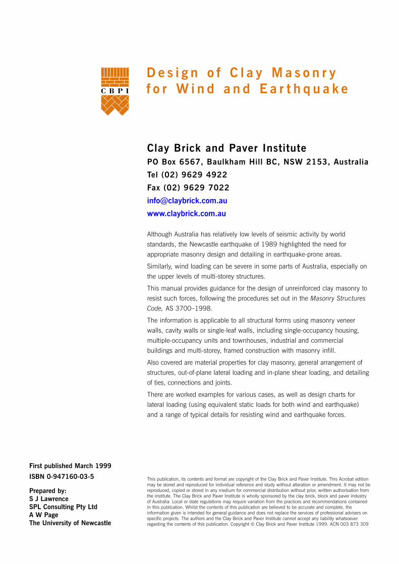
D e s i g n o f C l a y M a s o n r y f o r W i n d a n d E a r t h q u a k e
Clay Brick and Paver InstitutePO Box 6567, Baulkham Hill BC, NSW 2153, Australia
Tel (02) 9629 4922
Fax (02) 9629 7022
www.claybrick.com.au
Although Australia has relatively low levels of seismic activity by world
standards, the Newcastle earthquake of 1989 highlighted the need for
appropriate masonry design and detailing in earthquake-prone areas.
Similarly, wind loading can be severe in some parts of Australia, especially on
the upper levels of multi-storey structures.
This manual provides guidance for the design of unreinforced clay masonry to
resist such forces, following the procedures set out in the Masonry Structures
Code, AS 3700–1998.
The information is applicable to all structural forms using masonry veneer
walls, cavity walls or single-leaf walls, including single-occupancy housing,
multiple-occupancy units and townhouses, industrial and commercial
buildings and multi-storey, framed construction with masonry infill.
Also covered are material properties for clay masonry, general arrangement of
structures, out-of-plane lateral loading and in-plane shear loading, and detailing
of ties, connections and joints.
There are worked examples for various cases, as well as design charts for
lateral loading (using equivalent static loads for both wind and earthquake)
and a range of typical details for resisting wind and earthquake forces.
First published March 1999
ISBN 0-947160-03-5
Prepared by:S J LawrenceSPL Consulting Pty LtdA W PageThe University of Newcastle
1. Introduction ...................................................................................4
2. Types of Construction ....................................................................5
2.1 Housing ................................................................................................52.2 Multiple-occupancy domestic units ...........................................................52.3 Low-rise commercial and industrial buildings ............................................52.4 Multi-storey framed structures ..................................................................5
3. Masonry Elements ..........................................................................6
3.1 Veneer walls ..........................................................................................63.2 Cavity walls ...........................................................................................73.3 Masonry infill .........................................................................................73.4 Freestanding elements .............................................................................7
4. Material Properties .........................................................................8
4.1 Masonry units ........................................................................................84.2 Mortar ...................................................................................................84.3 Masonry properties .................................................................................84.4 Ties and connectors ................................................................................94.5 Damp-proof courses, joints and other accessories ......................................9
5. General Design Aspects .................................................................10
5.1 Loading conditions ................................................................................105.1.1 Wind loading ..........................................................................105.1.2 Earthquake loading .................................................................11
5.2 Structural behaviour ..............................................................................135.2.1 Wind loading ..........................................................................135.2.2 Earthquake loading .................................................................13
5.3 Mechanism of load transmission ............................................................145.3.1 Housing .................................................................................145.3.2 Framed structures ...................................................................145.3.3 Loadbearing structures .............................................................14
5.4 Tying and support of elements ...............................................................155.4.1 Slab/wall connections ..............................................................155.4.2 Shear capacity of membranes and joints ....................................155.4.3 Parapets and freestanding elements ..........................................15
6. Design of Walls for Out-of-Plane Load ...........................................16
6.1 Introduction .........................................................................................166.2 One-way vertical bending ......................................................................176.3 One-way horizontal bending ..................................................................186.4 Two-way bending .................................................................................18
6.4.1 Introduction ............................................................................186.4.2 Virtual work method ................................................................19
6.5 Veneer walls ........................................................................................216.6 Cavity walls .........................................................................................21
7. Design of Walls for In-Plane Load ..................................................22
7.1 Introduction .........................................................................................227.2 Shear wall design .................................................................................23
8. Design of Wall Ties, Connectors and Joints .....................................24
8.1 Introduction .........................................................................................248.2 Wall tie design .....................................................................................248.3 Design of connectors .............................................................................258.4 Seismic design of slip joints and joints containing membranes ..................258.5 Durability of ties and connectors ............................................................26
2
Ta b l e o f C o n t e n t s
CBPI Manual 4 : Design of Clay Masonry, First published March 1999

9. Worked Examples .........................................................................27
9.1 One-way vertical bending ......................................................................279.2 One-way horizontal bending ..................................................................279.3 Two-way bending (single-leaf wall) .........................................................289.4 Veneer wall ..........................................................................................299.5 Cavity wall ...........................................................................................299.6 Shear wall ...........................................................................................30
10. Design Charts ..............................................................................32
10.1 One-way vertical bending ......................................................................3310.2 One-way horizontal bending ..................................................................3310.3 Two-way bending .................................................................................34
10.3.1 110 mm without openings .......................................................3410.3.2 90 mm without openings ........................................................3510.3.3 110 mm with openings (no rotational restraint at sides) ..............3610.3.4 110 mm with openings (rotational restraint at sides) ..................3810.3.5 90 mm with openings (no rotational restraint at sides) ................4010.3.6 90 mm with openings (rotational restraint at sides) ....................42
11. Typical Details ..............................................................................44
1 Roof tie-down – cavity wall (low wind) ....................................................442 Roof tie-down – cavity wall (high wind – not cyclonic) ..............................443 Roof tie-down – cavity wall (earthquake) .................................................454 Roof tie-down – hollow-unit wall (earthquake and high wind) ...................455 Internal wall – ceiling joist perpendicular to wall ......................................466 Internal wall – ceiling joist parallel to wall ...............................................467 Cornice support (low wind) ....................................................................478 Wall-slab junction .................................................................................47
12. References ...................................................................................48
Figures
1 Variation of tie forces for flexible and rigid backups .....................................62 Application of AS 1170.4 ......................................................................113 Load transmission for a loadbearing structure ..........................................144 Idealised crack patterns for various wall configurations .............................165 Wall with opening divided into two sub-panels ........................................206 Shear wall behaviour ............................................................................22
Tables
1 Design wind pressures for housing (based on AS 4055) ...........................102 Design and detailing requirements for unreinforced masonry
in general structures .............................................................................123 Design and detailing requirements for domestic structures ........................124 Maximum wall pressures (kPa) for Type A ties at 600 mm centres .............24
3CBPI Manual 4 : Design of Clay Masonry, First published March 1999

4
1 . I n t r o d u c t i o n
This manual provides guidance for thedesign of unreinforced clay masonryto resist wind and earthquake forces.It follows the procedures set out in theMasonry Structures Code (AS 3700)1.For any aspects not covered here,reference should be made toAS 3700. Useful guidance on theinterpretation of AS 3700 can also befound in its Commentary2.Most masonry construction inAustralia is unreinforced and non-loadbearing. The common definitionof a non-loadbearing wall is one thatdoes not support any significantvertical loads other than its self-weight. Nevertheless these walls aresubjected to loading from wind andearthquake, as well as overallrequirements for robustness. Eveninternal partition walls are subjectedto earthquake loading. Walls with amoderate level of vertical loadingderive additional stability against faceloads and the most critical case forout-of-plane lateral loading istherefore a wall with nosuperimposed vertical load.Wind loading in parts of Australiacan be severe, and the level of loadincreases significantly in the upperstories of multi-storey buildings.
Unreinforced masonry has poorseismic performance because it isheavy and brittle with low tensilestrength and exhibits little ductility. Itis therefore unsuitable for areas ofhigh seismicity. However the level ofearthquake forces experienced inAustralia is moderate by worldstandards and unreinforced masonrycan be used in most instances,provided the structure is designedand detailed for the appropriateearthquake forces and built to therequired standard.This manual applies to all structuralforms using masonry veneer walls,cavity walls or single-leaf walls,including single-occupancy housing,multiple-occupancy units andtownhouses, industrial andcommercial buildings and multi-storey, framed construction withmasonry infill.It covers material properties for claymasonry, general arrangement ofstructures, specific design proceduresfor out-of-plane lateral loading andin-plane shear loading, and designdetailing of ties, connections andjoints. It does not cover design forvertical loading.Worked examples for various cases,design charts for lateral loading(using equivalent static loads for bothwind and earthquake) and typicaldetails for resisting wind andearthquake forces are included.
CBPI Manual 4 : Design of Clay Masonry, First published March 1999
2 . Type s o f C on s t r u c t i o n
2.1 HousingThe most common form of domesticconstruction in Australia is the single-occupancy house. The vast majorityof these are clad with clay masonry,with brick-veneer being the mostcommon form in the eastern states.Full-brick (cavity) construction ispopular in Western Australia andsingle-leaf construction using hollowunits is widely used in NorthQueensland. Because the walls ofhouses generally support only a lightroof load or no load at all, the criticaldesign load is usually lateral loadfrom wind or earthquake.In a veneer-walled house, the frame(timber or steel) is relied upon toresist the main forces includingvertical forces from the roof andlateral in-plane shear. In cavity andsingle-leaf construction, the masonrywalls must provide the resistance toall lateral forces, including in-planeshear. The latter can be thegoverning action where earthquakeforces are high.
2.2 Multiple-occupancydomestic units
Multiple-occupancy domestic units ofloadbearing masonry (commonlycalled three or four-storey walk-ups)are common in Australia and two-storey, semi-detached townhousesare increasingly popular. In thesebuildings the masonry walls usuallysupport concrete floor slabs and theroof structure and their sizes aredetermined accordingly. However,especially in upper storeys and intownhouses, wall designs can begoverned by resistance to out-of-plane forces.In these structures the masonry wallsmust also provide the resistance tolateral in-plane (shear) forces, withthe floor and roof acting asdiaphragms to distribute forces to thewalls.
2.3 Low-rise commercialand industrialbuildings
Where masonry panels are used ascladding for commercial andindustrial buildings, their structuraldesign is usually governed byresistance to wind and earthquakeforces. Economy in design is vital forthese walls. In these buildings, theconcrete or steel frame provides theoverall resistance to lateral forces andthe walls must have sufficient flexuralresistance to span between framemembers and other supports.Deflection compatibility betweenframes and walls is an importantconsideration.
2.4 Multi-storey framedstructures
Masonry cladding is popular formulti-storey structures with reinforcedconcrete or steel frames. In thesecases the walls provide the envelopeto protect the interior against theweather and are only required toresist lateral out-of-plane wind andearthquake forces.Often the inner leaf is an infill walltied to the frame. Design forcomposite action between framesand infill walls is beyond the scopeof this manual. Where compositeaction is not designed for, isolation ofinfill walls from frame movement isessential under heavy earthquakeloads. The external leaf is usually aveneer supported by angles or nibson the floor slabs.The walls in the upper storeys ofmulti-storey buildings may besubjected to high wind loads becauseof their height above the ground andthis will usually govern their design.
5CBPI Manual 4 : Design of Clay Masonry, First published March 1999
Various types of masonry elements
are used to make up a typical
masonry structure. These include
walls (that may be of veneer, cavity,
solid or diaphragm construction),
piers and freestanding elements
such as parapets and chimneys.
These elements behave in different
ways and their design must take
their particular characteristics into
account. Design of diaphragm walls
is beyond the scope of this manual.
3.1 Veneer wallsUnreinforced masonry is widely usedas a veneer in residential, lightcommercial and multi-storey, framedconstruction. Clay brick is by far themost common masonry choice forsuch applications. Veneers are non-structural elements and rely on thesupporting backup frame or wall andthe accompanying tying system forstability. Although they are non-structural, veneers are neverthelesssubject to wind and earthquakeloading. In particular the seismicperformance of veneers is importantbecause of their widespread use andthe high cost of repair if theirperformance proves to be inadequate.The behaviour of a veneer subjectedto face loading is quite complexbecause it depends upon the relativeflexibility of the veneer and backupsystem, as well as the stiffness andlocation of wall ties. These factorsaffect the degree of load-sharingbetween the veneer and backup andthe amount of load re-distributionthat can occur. There is also asubstantial difference in behaviourwhen the veneer is cracked ratherthan uncracked, because in itsuncracked state the veneer is usuallymuch stiffer than its backup.
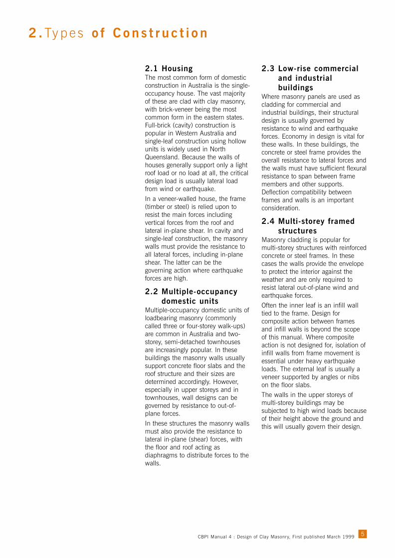
The masonry veneer itself usuallydoes not need to be designed. Fordesign purposes it is sufficient toknow the wall tie forces andcorresponding loads on the backupframe or wall. Typical distributions oftie force derived from an elasticanalysis3 are shown in Figure 1,where T indicates a tensile force inthe ties and C indicates a compressiveforce. In that study the veneer systemcomprised an external 110 mmbrickwork skin connected by medium-duty ties to either a flexible backupsystem (typically timber or steel studwall) or a rigid backup system(typically an internal masonry leaf).Both uncracked and cracked (at mid-height) conditions were examined.The marked difference in tie forces forthe cracked and uncracked states isshown in the figure.Under wind loading, the force ineach tie is directly influenced by thestiffness of the backup. The forcesare tensile in some locations for aflexible frame. Before the wall cracks,the top ties adjacent to the backupattract a much greater proportion ofthe load than would be expectedfrom their tributary area.
6
3 . Mason r y E l emen t s
Figure 1. Variation of tie forces for flexible and rigid backups
Masonry Veneer
Flexible Back-up
Uncracked Veneer Cracked Veneer
Ridgid Back-up
Back-up Wall
Face
Loa
ding
Tie
CBPI Manual 4 : Design of Clay Masonry, First published March 1999
This explains the logic of deemed-to-comply rules that require the numberof ties to be doubled in theselocations if the backup is flexible. Ifthe veneer cracks longitudinally atmid-height along a bed joint, there isa dramatic re-distribution of load inthe ties with the ties near the mid-height of the wall becoming heavilyloaded. This is particularly the casewhen the backup is a flexible frame.It is clear that ties play a crucial rolein this interaction and their strengthand stiffness are both important.A veneer wall relies on flashing anddamp-proof courses, in conjunctionwith weep-holes, to act as an effectivebarrier to moisture entering thebuilding. The presence of flashing anda damp-proof course will influencebehaviour under lateral load.
3.2 Cavity wallsCavity walls are constructed of twoleaves of masonry separated by acavity, typically 50 mm in width,intended primarily to prevent waterpenetration into the building. Thisform of construction has beenpopular in Australia and other partsof the world in this century becauseit provides a wall having goodthermal and strength propertieswithout the need to maintain anexternal coating.In resisting applied loads normal tothe face, cavity walls rely on theinteraction between the two leavesthrough the ties. Behaviour of thewhole system is complex and adetailed structural analysis would berequired in order to predict accuratelythe forces in individual components.This is usually impractical andsimplified rules are employed todesign the masonry leaves and theties.Proper detailing of flashings, damp-proof courses and weep-holes isessential to ensure that a cavity wallremains an effective, waterproofbarrier. As in the case of veneerwalls, the presence of flashing and adamp-proof course will affectbehaviour under lateral load.
3.3 Masonry infillUnreinforced masonry infill panelshave the potential to add considerablyto the strength and rigidity of aframed structure if they are designedand detailed for composite action.Interaction between infill and framedepends on the contact area at theinterface of the two components. Theextent of composite action willdepend on the level of lateral load,the degree of bond or anchorage atthe interfaces, and geometric andstiffness characteristics of the frameand infill masonry.The possibility of the mobilisation ofthe infill, especially to resist seismicloads, should be considered at thedesign stage. However in Australia itis good practice to leave gaps at thevertical edges and top of infill panelsto allow for long-term moistureexpansion of clay bricks. The infillpanels are secured to the frame byties that permit the desired relativemovements, and flexible sealant fillsthe gaps. In these cases, compositeaction will not occur until large framedeflections have taken place.Consideration of composite actionbetween masonry infill and frames isbeyond the scope of this manual.The design of infill panels that areisolated from the frame is usuallygoverned by flexural action to resistlateral out-of-plane forces. If there isthe possibility of a shallow archdeveloping within the thickness of thewall as it deflects, that should also beconsidered. However this archingaction is unlikely if expansion gapsare left between the wall and theframe and design for this action isdifficult because of the uncertainty ofits extent. Consequently AS 3700does not give design rules for thisarching. Infill wall panels are usuallydesigned as one-way or two-wayspanning plates of masonry withsimple supports provided by theframing members.
3.4 Freestanding elementsParapets and other freestandingelements are commonly used inunreinforced masonry structures.Because of the low flexural strength ofthe masonry, these elements have littleresistance to lateral load and must relyon gravity for stability. The presence ofa flashing or damp-proof course at thebase exacerbates the situation. Inaddition these elements are usuallylocated at or near the top of thestructure where the wind loading ishighest and the effects of seismicground motion are magnified by thedynamic response of the building.It is desirable to avoid the use offreestanding elements, or, if theymust be used, for them to besupported or locally reinforced toprovide flexural strength (see Section5.4.3).
7CBPI Manual 4 : Design of Clay Masonry, First published March 1999

Fired clay bricks have been in use
for at least 3500 years. Clay
masonry is particularly noted for its
attractive appearance, long life and
good loadbearing qualities. When
properly constructed and detailed it
provides one of the most functional
walling systems ever developed.
4.1 Masonry unitsThe Australian standard governingthe manufacture of masonry units isAS/NZS 44554. Units for use inmasonry construction are required byAS 3700 to satisfy that standard.Test methods are specified in acompanion standard AS/NZS 44565.Not all the tests described in thisstandard are required to be specified;AS 3700 clearly sets out which testsand properties are required in eachparticular case.
While durability classification,dimensions and aestheticrequirements must always beconsidered, the important propertiesof masonry units for walls designed toresist wind and earthquake loads are:• Absorption characteristics
compatible with the mortar to beused, so the required flexuraltensile bond strength is achieved.
• Lateral modulus of rupturesufficient for the required flexuraltensile strength.
4.2 MortarMortar is an important ingredient inmasonry construction because itscharacteristics have a stronginfluence on both the strength anddurability of the masonryassemblage. It is also the componentmost susceptible to site problemsrelated to mixing and batching.Mortar must be workable when wetand have sufficient strength and beadequately bonded to the masonryunits when set. The tensile bondstrength of masonry can vary fromzero to more than 1.0 MPadepending on the correct match ofmortar and unit properties, inparticular the match between mortarconsistency and unit suction.Selection of sand, cement, mixcomposition and admixtures such asair entrainer (when appropriate) areof vital importance for theachievement of the required tensilebond strength.
It is essential for the job specificationto refer to the type of cementassumed in the design if the mixproportions are specified. Forexample AS 3700 classifies thefollowing three mortars as M3:• 1:1:6 using GP cement• 1:1:5 using GB cement• 1:4 using masonry cement.A 1:1:6 mortar with GB cement isnot deemed-to-satisfy the M3classification. It is recommended thatthe job specification simply refer tothe classification (such as M3)assumed in the design, allowing theactual mortar composition to bedetermined on site.
4.3 Masonry propertiesBy definition, masonry is a compositematerial consisting of masonry unitsset in mortar. Because the units andmortar have different characteristics,masonry exhibits distinct directionalproperties with potential planes ofweakness being created by the lowtensile strength at each unit/mortarinterface. For resistance to wind andearthquake forces it is this bondstrength at the interface that isimportant, in both flexure and shear.
Flexural tensile strength (ƒ’mt ) isrequired by AS 3700 to be at least0.2 MPa for all masonry. This is a 95per cent characteristic value, whichmeans that 95 per cent of allmasonry in the building should bestronger than this design value andonly 5 per cent will be weaker. Thisbias is taken into account in settingthe required safety factors. SpecialMasonry, that is with strengths higherthan 0.2 MPa, requires quality controltesting during construction to verifythe required strengths are beingachieved. Design values as high as1 MPa can be taken for SpecialMasonry. The designer should bequite sure about the materialsspecified and the potential strengthbefore using a design strength higherthan the minimum value.
8
4 . Ma t e r i a l Pr ope r t i e s
CBPI Manual 4 : Design of Clay Masonry, First published March 1999

Shear strength on horizontal planesin clay masonry (ƒ’ms ) is defined byAS 3700 as 1.25 ƒ’mt but not greaterthan 0.35 MPa nor less than0.15 MPa. This property is thereforealso related to the basic bondingbetween masonry units and mortar.Additional shear resistance isprovided by the friction effect ofvertical load, that is accounted for bya shear factor prescribed in AS 3700(see Section 7.2).
4.4 Ties and connectorsMasonry wall ties are a structuralcomponent of the wall, not anoptional accessory. It is mostimportant that ties should beappropriately designed and specified,should have the necessary durabilityand be properly installed. Thestandard covering wall ties isAS 26996 with AS 29757 governingother connectors and accessories.Rarely, if ever, should the designerneed to refer to these standards, asthey are intended to control themanufacture of the ties andaccessories, not their use. AS 3700gives everything necessary for thespecification and use of thesecomponents.
Ties are classified based on strengthand stiffness as light duty, mediumduty and heavy duty. This rating isdetermined by tension andcompression tests on smalltie/masonry assemblages, with thetest results reflecting both thebehaviour of the tie itself and itsattachment to the masonry and theframe. Designers should use theprocedure in AS 3700 to determinethe classification required for eachparticular loading situation (seeSection 8.2). This requiredclassification should then be clearlyspecified on the documents.
Ties and connectors are commonlymade from steel with a protectivecoating. Where a high level ofdurability is required, stainless steelor polymer ties can be used.AS 3700 gives the requirements fordurability in terms of a rating fromR1 to R5 (see AS 3700 Table 5.1).Pending the publication of a revised
AS 2699, the means of satisfyingthese rating requirements are givenin AS 3700 Appendix F. The designershould specify the durabilityrequirement for ties and connectorson the documents.
4.5 Damp-proof courses,joints and otheraccessories
Damp-proof courses (DPC) mustcomply with the Australian standardAS 29048. Most loadbearingmasonry structures subjected toearthquake forces rely to some extenton the transfer of shear across theDPC to develop the necessaryresistance. The earthquake loadingcode AS 1170.49 was amended in1994 to permit friction on theseplanes to be considered as providingthe necessary restraint for generalstructures, where the design showsthe requirements are satisfied.AS 3700 provides friction shearfactors for the common DPCmaterials to allow these calculationsto be made (see Section 8.4). Ifshear resistance on a damp-proofcourse or other joint is a criticaldesign factor, the documents shouldclearly indicate the type of materialthat is required to satisfy the designassumptions.
9CBPI Manual 4 : Design of Clay Masonry, First published March 1999

5.1 Loading conditionsWind and earthquake producehorizontal lateral loads on a structure,which generate in-plane shear loadsand out-of-plane face loads onindividual members. While bothloading types generate horizontalforces, they are different in nature.Wind loads are applied directly to thesurface of building elements, whereasearthquake loads arise due to theinertia inherent in the building whenthe ground moves. Consequently therelative forces induced in variousbuilding elements are different underthe two types of loading.
5.1.1 Wind loadingWind is often the most important loadacting on a structure. Levels of windloading vary greatly throughoutAustralia, from moderate in theinterior to very high in the northerncyclonic regions. There are also localfactors to consider such astopography, surrounding shelter andheight above ground.Basic wind speeds and the numericmultipliers for dealing with factorssuch as topography are given by theWind Loading Code (AS 1170.2)10.This code is designed for use bystructural engineers and detailedillustration of its use is beyond thescope of this guide.For housing structures, wind loads aredetermined from a classificationsystem given in Wind Loads forHousing (AS 4055)11. This systemuses regions, terrain categories,shielding categories and topographic
categories to determine the windclassification. Provided the structure iswithin certain restrictions on height,shape and slope of roof, it is classifiedas N1 to N6 for non-cyclonic regionsand C1 to C4 for cyclonic regions.This classification then determines thedesign wind speeds for the ultimatelimit state, ranging from 34metres/second to 86 metres/second.These wind speeds are used to deriveforces on the structure by consideringpressure coefficients based on theshape and size of the structure andthe presence of openings.The following table is provided as aguide to wind pressures when thewind classification for a housing siteis known. It is not intended to replacethe proper use of AS 4055. Thepressures are for ultimate-strengthlimit-state design and are derivedusing the coefficients applicable tothe worst case for general wall areasgiven in AS 4055 Appendix B.Wind acting on a structure causesthree main effects that must beaccounted for in design: out-of-planebending, in-plane shear and upliftcausing direct tension. Design for thefirst two is covered in Section 6 andSection 7. The effect of the thirdshould be considered for individualmembers when they are designed forflexure and shear. Net direct tensionon the cross-section of a masonrymember must be avoided in designas the tensile strength of the materialis considered to be zero in suchcircumstances.
10
5 . Gene r a l Des i g n A sp e c t s
Table 1. Design wind pressures for housing (based on AS 4055)
Wind Ultimate wind Design wind
classification speed (m/sec) pressure (kPa)
N1 34 0.7
N2 40 1.0
N3 50 1.5
N4 61 2.2
N5 74 3.3
N6 86 4.4
C1 50 2.0
C2 61 3.0
C3 74 4.4
C4 86 6.0
CBPI Manual 4 : Design of Clay Masonry, First published March 1999
5.1.2 Earthquake loadingEarthquake loading is the forcegenerated by horizontal and verticalground movements due toearthquake. These movements induceinertial forces in the structure, relatedto the distributions of mass andrigidity and the overall forces producebending, shear and axial effects in thestructural members. Earthquake loadsare different in nature to wind loadsand can produce different effects insome cases.Earthquake loading is governed byAS 1170.4 and backgroundinformation is given in itsCommentary12. Until the advent ofthis new earthquake loading code in1993, unreinforced masonrystructures were usually designed fordead, live and wind loads, withseismic loading often not beingconsidered. The 1989 Newcastleearthquake highlighted the need forseismic design and now, with theincorporation of AS 1170.4 into theBuilding Code of Australia,consideration of seismic effects ismandatory for all structures. Becauseof the low levels of Australianseismicity, it is feasible to use
properly detailed and constructedunreinforced masonry in most areas.Masonry veneer attached to a ductileframe of timber or steel is considerednon-structural and requires nospecific design for earthquake if itcomplies with AS 3700. Unreinforcedmasonry (solid or cavity walls) isclassed as non-ductile and must bedesigned to remain essentially elastic.A non-ductile structure is required tocarry a higher level of applied loadthan a ductile structure. As with allseismic design, clear load paths mustbe established and irregularities inplan and elevation must beconsidered. The establishment of loadpaths includes the effectivetransmission of seismic forces acrossthe various connections and any otherdiscontinuities in the structure. To thisend the influence of flashings,membrane-type damp-proof coursesand slip joints must be considered.For simplicity, earthquake loadingcan be converted to equivalent staticforces with appropriate allowance forthe dynamic characteristics of thestructure, foundation conditions, etc.
11
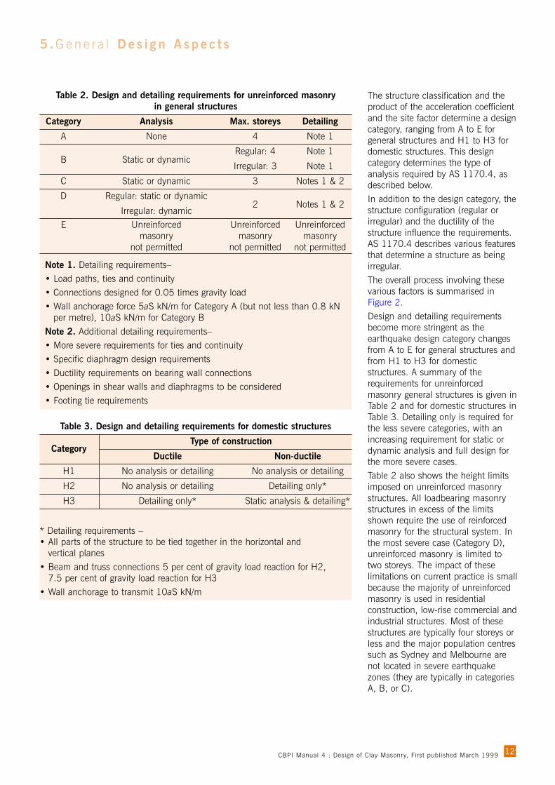
This approach is sufficient for mostmasonry structures that normallyhave a short fundamental period andlow dynamic response.AS 1170.4 provides loadcombinations for seismic designagainst strength and stability limitstates. Serviceability is not consideredfor seismic design but must beconsidered in detailing connectionsfor serviceability performance.In the application of AS 1170.4 astructure classification, accelerationcoefficient and site factor are used.The structure classification forgeneral structures is related to theimportance of the structure and itspost-earthquake function. Theacceleration coefficient (a) isdetermined by the geographiclocation of the structure and the sitefactor (S) depends on the soil profileof the site.
StructureClassification
AccelerationCoefficient
(GeographicLocation)
StructureConfiguration(Regular orIrregular)
Type ofStructure
(Ductile orNon-Ductile)
Site Factor(Soil Profile)
EarthquakeDesign Category
(A to E orH1 to H3)
Detailing and/orAnalysis
Requirements
Figure 2. Application of AS 1170.4
CBPI Manual 4 : Design of Clay Masonry, First published March 1999
5 . Gene r a l Des i g n A sp e c t s
The structure classification and theproduct of the acceleration coefficientand the site factor determine a designcategory, ranging from A to E forgeneral structures and H1 to H3 fordomestic structures. This designcategory determines the type ofanalysis required by AS 1170.4, asdescribed below.In addition to the design category, thestructure configuration (regular orirregular) and the ductility of thestructure influence the requirements.AS 1170.4 describes various featuresthat determine a structure as beingirregular.The overall process involving thesevarious factors is summarised inFigure 2.Design and detailing requirementsbecome more stringent as theearthquake design category changesfrom A to E for general structures andfrom H1 to H3 for domesticstructures. A summary of therequirements for unreinforcedmasonry general structures is given inTable 2 and for domestic structures inTable 3. Detailing only is required forthe less severe categories, with anincreasing requirement for static ordynamic analysis and full design forthe more severe cases.Table 2 also shows the height limitsimposed on unreinforced masonrystructures. All loadbearing masonrystructures in excess of the limitsshown require the use of reinforcedmasonry for the structural system. Inthe most severe case (Category D),unreinforced masonry is limited totwo storeys. The impact of theselimitations on current practice is smallbecause the majority of unreinforcedmasonry is used in residentialconstruction, low-rise commercial andindustrial structures. Most of thesestructures are typically four storeys orless and the major population centressuch as Sydney and Melbourne arenot located in severe earthquakezones (they are typically in categoriesA, B, or C).
12
Table 2. Design and detailing requirements for unreinforced masonry in general structures
Category Analysis Max. storeys Detailing
A None 4 Note 1
B Static or dynamic Regular: 4 Note 1
Irregular: 3 Note 1
C Static or dynamic 3 Notes 1 & 2
D Regular: static or dynamic
Irregular: dynamic2 Notes 1 & 2
E Unreinforced Unreinforced Unreinforced masonry masonry masonry
not permitted not permitted not permitted
Note 1. Detailing requirements–• Load paths, ties and continuity• Connections designed for 0.05 times gravity load• Wall anchorage force 5aS kN/m for Category A (but not less than 0.8 kN
per metre), 10aS kN/m for Category BNote 2. Additional detailing requirements–• More severe requirements for ties and continuity• Specific diaphragm design requirements• Ductility requirements on bearing wall connections• Openings in shear walls and diaphragms to be considered• Footing tie requirements
Table 3. Design and detailing requirements for domestic structures
Type of constructionCategory
Ductile Non-ductile
H1 No analysis or detailing No analysis or detailing
H2 No analysis or detailing Detailing only*
H3 Detailing only* Static analysis & detailing*
* Detailing requirements –• All parts of the structure to be tied together in the horizontal and
vertical planes• Beam and truss connections 5 per cent of gravity load reaction for H2,
7.5 per cent of gravity load reaction for H3• Wall anchorage to transmit 10aS kN/m
CBPI Manual 4 : Design of Clay Masonry, First published March 1999
Design requirements (domestic)No analysis is required for domesticstructures in categories H1 and H2because the system already in placeto resist lateral wind load shouldprovide sufficient wall, floor and roofdiaphragms to resist horizontalearthquake loading. Analysis isrequired for non-ductile construction,such as solid and cavity walls ofunreinforced masonry, in earthquakedesign category H3. The total baseshear, however, has been simplifiedto 15 per cent of the total gravityloads (see Clause 3.4.2 ofAS 1170.4).Torsional effects need not beconsidered for regular domesticstructures (defined as rectangularstructures with a ratio of length towidth not exceeding 1.2). Forirregular domestic structures,torsional effects are catered for byincreasing the design load effects by25 per cent (see Clause 3.4.4 of AS 1170.4).
Detailing requirements (domestic)Earthquake resistance of domesticconstruction depends more on gooddetailing than structural analysis.Domestic construction derives itsresistance from overall systembehaviour that can only occur if allthe parts of the structure areadequately connected. The intentionof structural detailing requirements isto ensure this connection is provided,so all forces on the structure aretransferred to the foundations.There are no specific structuraldetailing requirements for H1category for all types of constructionand H2 category for ductileconstruction (see Clause 3.2 of AS1170.4). Nevertheless it is goodpractice to ensure that allcomponents are tied together.Structural detailing requirements fornon-ductile construction in H2category and for all construction inH3 category include the following:• Horizontal resistance must be
provided for connections of beamsand trusses to their supports (seeClause 3.3.1 of AS 1170.4).
• External walls must be anchored toroofs and floors for horizontalsupport and internal loadbearingwalls must be restrained at theirtop and bottom (see Clause 3.3.2of AS 1170.4).
Other measures can be taken toimprove horizontal earthquakeresistance, for example byincorporating sub-floor braces fordiscrete footings (see AS 1170.4Appendix C, Clause C3.1 forguidance). Design of connectors isdiscussed in Section 8.3.Attention should be paid particularlyto detailing of unreinforced ‘non-structural’ masonry components, asthese are the elements most at riskduring an earthquake. Non-ductilecomponents such as unreinforcedmasonry gable ends, internal non-loadbearing walls, chimneys andparapets require restraint to resist aforce of 1.8aS times the weight ofthe component. This is an importantrequirement applicable to allcategories (see Clause 3.5 ofAS 1170.4).
5.2 Structural behaviour5.2.1 Wind loadingTraditionally, masonry structures weremassively proportioned to providestability and prevent tensile stresses.In the period following the SecondWorld War, traditional loadbearingconstruction was replaced bystructures using the shear wallconcept, where stability against lateralloads is achieved by aligning wallsparallel to the load direction. Lateralforces are therefore transmitted to thelower levels by in-plane shear. Whencombined with the use of concretefloor systems acting as diaphragms,this produces robust, box-likestructures with thin walls and thecapacity to resist lateral load.
Loadbearing structures of this typeoffer an economical alternative toframed construction for low andmedium rise buildings, particularlyfor structures with repetitive floorlayouts. For these structures the wallssubjected to face loading must bedesigned to have sufficient flexuralresistance and the shear walls musthave sufficient in-plane resistance.The alternative structural formconsists of a frame, usually of steel,timber or concrete, which resists thelateral forces by bending (frameaction). The masonry walls attach tothis frame as a cladding anddistribute the applied lateral forcesinto the framing members. In thissystem the masonry walls aredesigned for local flexural action only.
5.2.2 Earthquake loadingIn buildings subjected to earthquakeloading the walls in the upper levelsare more heavily loaded by seismicforces because of dynamic effects,and are therefore more susceptible todamage caused by face loading. Theresulting damage is consistent withthat due to wind or other out-of-planeloading. Racking failures are morelikely to occur in the lower storeyswhere shear forces are greatest andare characterised by stepped diagonalcracking. This damage does notusually result in wall collapse but cancause considerable distress. Rackingdamage can also occur in structureswith masonry infill when large framedeflections cause load to betransferred to the non-structural walls.Both plan and elevation symmetry isdesirable to avoid torsional and soft-storey effects. Compact plan shapesbehave better than extended wings. Ifirregular shapes cannot be avoided,then more detailed earthquakeanalysis may be necessary. In somecases it may be possible to separatewings by suitable isolation joints andthereby convert the structure into aseries of regular shapes. Appendix Aof AS 1170.4 provides guidance forthe designer on features that result ina structure being classified as regularor irregular.
13CBPI Manual 4 : Design of Clay Masonry, First published March 1999

5.3 Mechanism of loadtransmission
The fundamental aspect common toboth wind and earthquake loading isthat load imposed on the structuremust be transmitted through a loadpath to the foundation. It is importantfor this load path to be identified andthe respective structural elementsdesigned for the part they play in it.The load path is different forstructures that rely on the masonrywalls as loadbearing elements andthose where the masonry forms aninfill or a veneer applied to astructural frame.
5.3.1 HousingThe mechanisms of load transfer inmasonry housing are different for cavityconstruction and masonry veneer.The inner leaf of cavity constructionsupports the vertical load of anyupper floors and the roof, while theouter leaf provides the weather-resistant cladding. Lateral out-of-plane forces are shared between thetwo leaves in proportion to their
respective stiffness. The inner leaf isusually much stiffer because of itsload supporting function, andtherefore resists a larger portion ofthe lateral load. The extreme case iswhen the outer leaf is attached onlyby the ties and is designed as aveneer on a stiff backup. Cross wallswithin the building, that might eitherbe of masonry or framedconstruction, act to transfer lateralshear forces to the footings.For masonry veneer construction, thebuilding frame supports all theapplied forces (vertical andhorizontal) while the masonrycladding protects against the weather.The face loads applied to the wallsare transmitted to the backup framethrough the ties. The framingmembers then transfer the forces toshear diaphragms such as floors,ceilings and roof. Lateral shearresistance is provided by the framethat must be fitted with suitablebracing to transfer forces to thefootings. It is only necessary to checkthe masonry veneer for its ability to
span in flexure between ties and theAS 3700 minimum spacings willusually ensure this capacity isadequate. To limit the size of anycrack in the veneer, the deflection ofthe structural backing is limited byAS 3700 (Clause 7.7.2(b)) to spandivided by 300.
5.3.2 Framed structuresIn a framed structure, load istransferred from the face-loaded wallsto the framing members through theirconnections. The framing membersthen act together to resist the lateralforce by sway action or braced-trussaction, thereby transferring the forceto the foundations. The importantelements to be considered by themasonry designer are the masonrywalls (in out-of-plane flexure) and theconnections. Isolation of the masonrywalls from any large frame swaymovements might also be necessary.
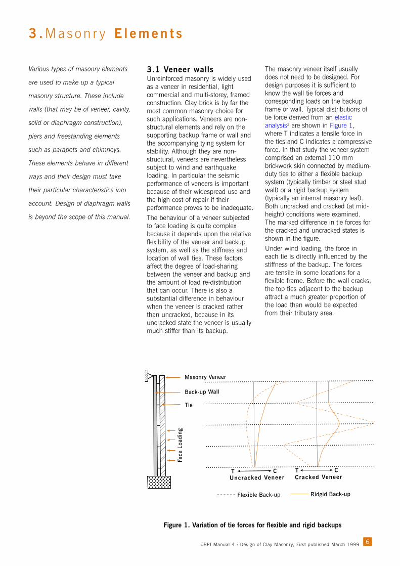
5.3.3 Loadbearing structuresThe basic mechanism of lateral loadtransmission for a loadbearingstructure is shown in Figure 3. Wallsaligned in a plane normal to the loadare subjected to face loads and spanvertically between the floors and, insome cases, horizontally betweenloadbearing walls. The concrete floorsthen act as rigid diaphragms andtransfer the load to the shear walls,which in turn transmit the forces tothe ground by in-plane shear.The resulting structures are usuallyquite robust, with relatively short-spanconcrete slab systems supported bynumerous walls running in bothprincipal directions. The effectiveperformance of this system dependson the ability of the individualmasonry elements to sustain theirshare of the load, as well as thecapability of the connections betweenthe elements to transmit theappropriate forces. The elements to beconsidered by the masonry designerare out-of-plane flexural action, in-plane shear action and connectionsbetween structural elements.
14
5 . Gene r a l Des i g n A sp e c t s
Figure 3. Load transmission for a loadbearing structure
Shear action in cross walls
Flexural actionin walls
Diaphragm action infloor and roof slabs
WIND FORCE
CBPI Manual 4 : Design of Clay Masonry, First published March 1999

5.4 Tying and support of elements
The correct performance of ties andconnections between structuralelements is just as important as thebehaviour of the elementsthemselves, especially underearthquake loading. Any failure orinadequacy of the connections canlead to catastrophic collapse of thestructure. Important connectionsinclude the following:• Ties between the leaves of a
cavity wall.• Ties between a masonry veneer
and its backup.• Roof tie-downs.• Connectors between the edges of
a non-loadbearing wall panel andits supports.
• Connectors attaching masonry infillto a structural frame.
• Connections providing support fornon-structural components such asparapets and gables.
• Slip joints, DPC membranes and flashings.
It is important to remember that tiesand connectors are usually requiredto provide resistance in one directiononly, and they must not undulyrestrain movement in otherdirections. These considerations leadto the test requirements for obtainingwall tie ratings, where they must besubjected to a significant lateralmovement prior to application of thecompressive or tensile force.Similarly, in the case of slip jointsand DPC membranes, movementsdue to thermal and moisture strainsand long-term expansion orshrinkage of the masonry units mustbe allowed to occur without causingdistress in the structure. Underearthquake loading the behaviour ofties, connectors and joints undercyclic reversing load must also betaken into account.
5.4.1 Slab/wall connectionsTo satisfy the requirements ofAS 1170.4 a slab-wall connectionmust be capable of transmitting ahorizontal force of 10aS kN permetre length of wall (where a is theacceleration coefficient and S is the
site factor). For unreinforced masonrythis requirement creates potentialserviceability problems, since if apositive form of attachment isadopted, the long-term movementsmentioned above will be restrained,thus inducing cracking in themasonry. If a positive form ofconnection is not adopted, thenreliance must be placed on thetransfer of the seismic force byfriction. Design for friction is coveredin Section 8.4.
5.4.2 Shear capacity of membranesand joints
Membrane-type damp-proof coursesare widely used in Australia as abarrier at the base of walls to preventthe passage of moisture from theground to the structure. These samemembranes are also used forflashings and in slip joints. The useof these membranes in masonrywalls has significant structuralimplications as both in-plane andout-of-plane forces must betransmitted across the jointcontaining the membrane. Design ofthese joints is covered inSection 8.4.
5.4.3 Parapets and freestandingelements
Freestanding elements such asparapets must be adequatelysupported and tied to the structure.They can be subjected to high loads,especially from seismic action, wherethe dynamic response of the buildingcan magnify the force. The provisionsof AS 1170.4 allow for this effect bythe application of a heightamplification factor with a maximumvalue of 2.0 (see Clause 5.4.2 ofAS 1170.4). This is a simplification ofwhat is quite a complex phenomenon.Grouted and reinforced cavityconstruction or grouted and reinforcedhollow clay units can be used toprovide sufficient resistance for thispurpose. Alternatively, unreinforcedparapets can be tied to the mainstructure or proportioned to spanhorizontally between returns or piersthat are designed to provide overallstability. Examples of details for tyingparapets and chimneys back to a roofstructure are shown in AS 382613.
15CBPI Manual 4 : Design of Clay Masonry, First published March 1999
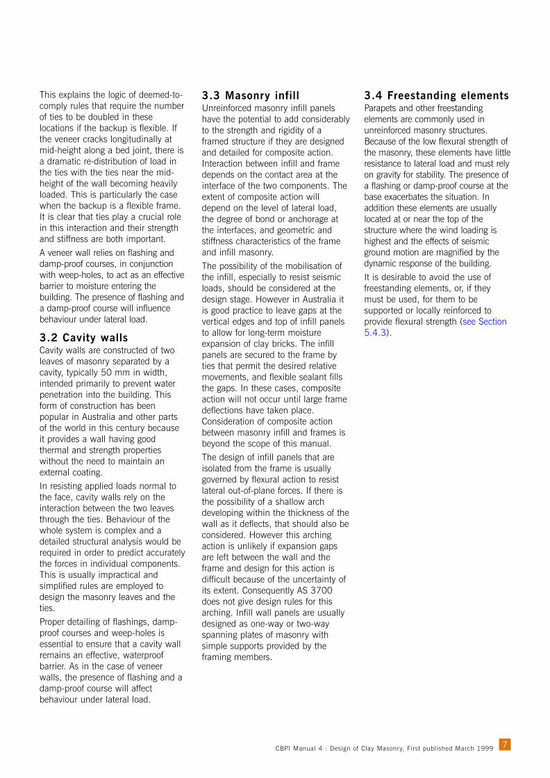
6.1 IntroductionFor lateral out-of-plane loading, whether it arises from wind or earthquake, theresponse of the structural element is calculated by considering the load as anequivalent static uniform pressure. Although there is a fundamental differencein the type of load caused by wind and earthquake, there is no difference indesign procedure between the two.Masonry elements subjected to out-of-plane loading resist the loads by flexuralaction. The load capacity of unreinforced masonry wall panels depends uponthe dimensions and support conditions, the level of compressive stress in thewall and the tensile strength of the masonry. The presence of door and windowopenings also has a strong influence on the behaviour. For veneer or lightlyloaded panels where the level of compressive stress is low, flexural tensilestrength is particularly important. Determination of design loads for wind andearthquake is discussed in Section 5.1.Masonry walls behave differently under simple bending in one direction, forexample between top and bottom supports, and bending in two directions,such as when the wall has support on two or more adjacent edges. This is aresult of the flexural action of plates under distributed loading and the differentflexural properties of masonry normal to and parallel to the bed joints. Mostwalls are designed to have support conditions that result in two-way bendingbecause this action is much stronger than simple one-way bending.
16
6 . Des i g n o f Wa l l s f o r Ou t - O f - P l a n e L o ad
Walls without openings:
Walls with openings:
HV
1 D1 2 D2
3 D3 4 D4
5 D5Typical opening
6 D6
Figure 4. Idealised crack patterns for various wall configurations
Supports
CBPI Manual 4 : Design of Clay Masonry, First published March 1999
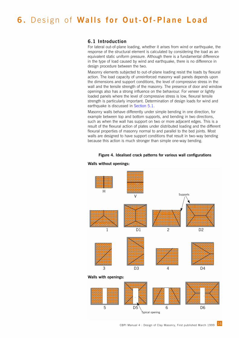
This manual’s design charts givepermissible lengths and heights forwalls with a range of supportconditions and for various windpressures. Masonry walls crack inparticular patterns under faceloading, depending on the supportconditions and dimensions. Figure 4shows the idealised cracking patternsthat occur for various wallconfigurations, with edge supportsindicated by darker shading. Thecrack lines shown, together withcracks along continuous or restrainededges, allow a mechanism to form,at which point the wall is consideredto have failed.Two types of edge restraint areconsidered in the design charts:lateral restraint and full rotationalrestraint. The latter can be referred toas a fixed edge. The other conditionconsidered is a free edge.The twotypes of restraint are defined as:• Lateral restraint occurs when the
edge of the masonry wall only hasrestraint in the lateral (out-of-plane) direction and there is nocapacity to transmit a momentacross the edge. Control joints orisolation joints incorporated withinthe wall provide such a case andthe bed joint at the base of a wallis considered to be of this type.
• Edge fixity occurs when the edge ofthe wall is restrained against lateralmovement and rotation. Thiscondition can occur when a wallextends continuously past asupport for a sufficient distance orwhere a wall returns for a sufficientdistance around a corner. AS 3700does not give any guidance as towhat return distance around acorner to the edge of the nearestopening or end of the wall issufficient for this purpose. In theabsence of other guidance, adistance of at least ten times thewall thickness can be considered areasonable minimum. It is difficultto achieve full rotational restraintby building the edge of a wall upto a supporting member andincorporating metal ties. Such acondition should usually beconsidered as providing lateralrestraint only.
The top of a masonry wall might be considered either to have lateral restraintor to be a free edge. The base of a wall is considered to have lateral restraintonly.
6.2 One-way vertical bendingThe most common form of one-way bending is vertical bending. In this mode,the wall panel acts as a simple beam between top and bottom supports, withthe main flexural stresses acting across the bed joints. This mechanism resultsin a brittle failure. When a bed joint crack occurs in masonry acting in this waythe joint has no further resistance to applied moment.Resistance to vertical bending is only provided by the flexural tensile strengthof the masonry, although it is enhanced by any superimposed vertical load onthe wall. This superimposed load, if any, is taken into account in the designprocedure by considering the resulting compressive stress as acting uniformlyon the bed joint and partially relieving the tensile stress due to bending.Because a wall under pure vertical bending fails in a brittle manner and theflexural tensile strength of masonry is usually quite low, there are few caseswhere one-way spanning walls can be justified. Wherever possible wallsshould be provided with additional support along one or both the verticaledges, or if this is not practical the use of reinforced elements should beconsidered.The design procedure for vertical bending is based on the moment ofresistance Mcv which is calculated as follows.
....................................................................(1)
Where –
f = Capacity reduction factor (0.6 for bending).
kmt = 1.0 for clay masonry.
ƒ’mt = Characteristic flexural tensile strength of the masonry (0.2 MPa exceptin the case of Special Masonry).
Zd = Section modulus of the bedded area.
ƒd = Minimum design compressive stress due to superimposed vertical load(usually based on 80 per cent of the dead load).
However the amount of vertical compression force ƒd that can be used toenhance the bending resistance is limited to , which is 0.24 MPa formost masonry (see AS 3700 Equation 7.4.2(3)).For a case where the flexural tensile strength ƒ’mt is zero (for example at adamp-proof course or slip joint) the moment of resistance is:
..........................................................................................(2)
Where ƒd is limited to 0.36 MPa.
The use of this design procedure is illustrated with a worked example inSection 9.1 and a design chart is given in Section 10.1.
ddcv ZƒM =
dddmtmtcv ZƒZkM += ƒ’φ
17
mtmtk ƒ’2φ
CBPI Manual 4 : Design of Clay Masonry, First published March 1999
6.3 One-way horizontal bendingIt is possible for portions of a wall to act in what is called one-way horizontalbending. In these cases, the section of masonry is supported at the two sidesbut not at the top and bottom. This might occur for example in a strip ofmasonry over a window or door opening where the top of the wall is notsupported. Such cases can be designed using the AS 3700 provisions forhorizontal bending.The design procedure for horizontal bending is based on the moment ofresistance Mch, which is given by the lower of two expressions:
................................................................(3)
..........................................................(4)
Where –kp = A perpend spacing factor (1.0 for traditional stretcher-bonded
brickwork).ƒ’ut = The characteristic lateral modulus of rupture of the masonry units (0.8
MPa in the absence of test data).Zu = The lateral section modulus of the masonry units.
Zp = The lateral section modulus based on the bedded area of the perpendjoints.
The other symbols are as defined previously. Note that Zp is less than Zu if theperpend joints are not completely filled; otherwise they will be equal. Thelateral section moduli and the lateral modulus of rupture are determined aboutthe axis of bending in the wall, that is, a vertical axis.The first expression is derived from an empirical fit of test results; the secondexpression is based on a model of failure through units and perpends. A thirdexpression given in AS 3700 has the effect of limiting the amount of verticalcompression force ƒd, used to enhance the bending resistance, to ƒ’mt, that is0.2 MPa for most masonry.The use of this design procedure is illustrated with a worked example inSection 9.2 and a design chart is given in Section 10.2.
6.4 Two-way bending6.4.1 IntroductionWall panels with support on at least two adjacent sides undergo a combinationof vertical and horizontal bending. This action provides more opportunity forload sharing between various parts of the wall as cracks develop and leads toa less brittle behaviour. It is therefore more desirable than one-way bending.Observations of cracking in numerous tests have led to the identification ofcharacteristic patterns that depend on the wall support conditions. Each ofthese cracking patterns divides the wall panel into a number of sub-plates thatcan be considered as being joined by hinges at their edges. While the exactdistribution of moment along these crack lines is unknown, the total residualmoment capacity of a crack line has been shown to relate to the shape of theunits and the basic bond strength ƒ’mt. The collection of sub-plates in thecracked wall forms a mechanism that allows the wall to deflect, at almostconstant load, until the total deflection is sufficient to cause collapse. Thispseudo-ductile behaviour is the basis of the virtual work method of analysisnow adopted in the AS 3700 design provisions14.
ƒ’ ƒ’ )56.044.0( pmtuutch ZZM +=φ
ƒ’ƒ’ d
mt
dmtpch Z
ƒkM )1(2 += φ
18
6 . Des i g n o f Wa l l s f o r Ou t - O f - P l a n e L o ad
CBPI Manual 4 : Design of Clay Masonry, First published March 1999

Some idealised cracking patterns areshown in Figure 4. The crackingpattern is always consistent with theshape and boundary conditions ofthe panel. When the top of a wall issupported the first crack to develop isusually horizontal in a bed joint atapproximately the mid-height of thepanel. This crack is difficult to detectand will almost disappear if the wallis unloaded.When adjacent vertical andhorizontal edges are supported,diagonal crack lines form and radiatefrom at or near the corner. Thesecracks form in the bed and perpendjoints and their angle is thereforegoverned by the length-to-heightdimensions of the masonry units.The cracks extend until they reach anedge or another failure line.When a panel is high compared to itslength, a vertical crack develops atapproximately mid-length. Thisfailure line extends to the top of thewall if unsupported or to theintersection of the diagonal failurelines at both top and bottom. Whenvertical edges have rotationalrestraint (for example because ofcontinuity) they will crack eitherbefore, or at the same time as, thediagonal cracks develop.The presence of vertical load appliedsimultaneously with the lateral loadcan enhance the strength of thepanel and this will be reflected in ahigher value of Mch. When the loadbecomes substantial, such as wherein-plane arching can develop due tothe panel edges bearing against thestructural frame as the wall deflects,the wall strength can be substantiallyincreased. However there is noreliable design method for this action.
6.4.2 Virtual work methodThe lateral load design methodintroduced in the revised AS 3700 isbased on the virtual work approach.This semi-empirical method relies onthe identification of a particularcracking pattern (as outlined above)and certain assumptions about thematerial properties. The method wasdeveloped by examining crackpatterns in a large number of test
panels and relating the ultimate load capacity of the walls to the energydeveloped on the crack lines. This was then calibrated to give the closest fit tothe results and applied to predict the behaviour of other cases. The calibrationinvolved deriving an equivalent torsional stress that is closely related to thebasic flexural tensile strength ƒ’mt. This derivation is the only empirical step inthe development of the method.The assumed behaviour of the three types of crack lines is as follows.• Horizontal crack line in a bed joint – assumed to have no residual moment
of resistance after cracking. This type of crack has virtually no influence onthe overall strength.
• Vertical crack line – results from failure through masonry units and perpendsor from the stepped shearing failure alternating between the mortar jointsand perpends. The moment capacity is influenced by the lateral modulus ofrupture of the masonry units and the flexural tensile strength of the masonryand is expressed by Mch.
• Diagonal crack line propagating from a corner – results from torsionalshearing action in the mortar bed joints and perpends. The geometry of themasonry units determines the slope of the line and the tensile strength of themasonry determines the flexural strength along the crack, expressed as Mcd.This type of crack has the greatest effect of the three in determining theoverall strength.
The virtual work method can be summarised as follows. A mechanism ispostulated, based on the assumed crack pattern for the given wall and thismechanism is given a unit (virtual) deflection. The incremental internal energy(work done on the hinge lines) is the sum along all crack lines of the productsof moment of resistance and angle of rotation. The incremental external workdone is the sum over all panel segments of the products of load and deflectionfor each segment centroid.Equating the internal energy and the external work done results in an equationthat can be solved to derive the load resisted by the cracked panel at the timethe mechanism is formed. This predicted load capacity depends on geometricalfactors for the wall and the material properties that are expressed as thehorizontal moment capacity Mch (see Equations (3) and (4)) and the diagonalmoment capacity Mcd (see Equation (5)).
The diagonal bending moment capacity is given in AS 3700 as:
.....................................................................................(5)
Where –
ƒ’t = The equivalent torsional strength
Zt = The equivalent torsional section modulus, measured normal to thediagonal crack line, as calculated by the expressions given in AS 3700(Clause 7.4.4).
Other symbols are as defined previously.
Treatment of openingsWhen a wall panel contains door and window openings these will causevariations to the crack pattern (see Figure 4). The virtual work method can stilldeal with these cases by considering sub-panels on each side of the openingand using the energy developed on the actual crack lines. Any influence of aframe around the opening, or any other effect of a door or window structure isignored. However the load applied to the door or window is taken into accountas a part of the overall load on the wall.
mt25.2= ƒ’
ƒ’ ttcd ZM φ=
19CBPI Manual 4 : Design of Clay Masonry, First published March 1999

Whereas a rigorous analysis could consider the resistance along the crack linesfor the expected crack pattern, the tabulated coefficients in AS 3700 are basedon a simplification. For these purposes, the opening is treated as if it extendedthe full height of the wall. There is no account taken of contribution to theresistance from any masonry between the edges of the opening. However theload on the section between the edges of the opening is included for thecalculation of the work done. This is equivalent to designing the panel on eachside of the opening as an independent panel with a free edge having a lineload applied.Figure 5 shows a panel with an opening and indicates how it is divided intosub-panels.
Application of methodThe general formula for the virtual work method is:
.......................................................................(6)
Where–wd = The predicted lateral load capacity of the panel.
af = The aspect factor depending on the geometry.
Ld = Design length (see below).
k1 & k2 = Coefficients depending on the edge restraints and the geometry.
Mch and Mcd are as defined previously.
The design length and design height both depend on the support conditions forthe wall and the presence of openings. They are found as follows:Design length – When only one vertical edge of a wall is supported, the designlength is the actual length of the wall. When both vertical edges are supported,the design length is half the actual length. If there is an opening in the wall,the edges of the opening are considered as if they are free edges and thedesign length is the distance from the edge of the wall to the edge of theopening.
)(2
212 cdchd
ƒ MkMkL
aw +=
20
6 . Des i g n o f Wa l l s f o r Ou t - O f - P l a n e L o ad
Figure 5. Wall with opening divided into two sub-panels
Opening
Sub-panel withfree right edge
Sub-panel withfree left edge
CBPI Manual 4 : Design of Clay Masonry, First published March 1999

6.5 Veneer wallsThe veneer in a veneer wall does not require structural design but should bechecked for its capacity to resist the load applied to it by spanning between theties in flexure. Usually this will not be critical for the maximum tie spacingsspecified in AS 3700.The structural backup to a veneer wall must be designed to resist the total loadapplied to the wall. AS 3700 defines a flexible backup as one with stiffnessless than or equal to half the stiffness of the uncracked veneer. All otherbackups are classed as stiff. Examples of flexible backups are steel frames andtimber frames, whereas stiff backups include concrete and masonry walls. Fora flexible backup and a stiff non-masonry backup, design should be inaccordance with the appropriate code and is beyond the scope of this manual.When the backup is a stiff masonry wall, it should be designed in accordancewith this manual (see Section 6.4). For a flexible backup, AS 3700 limits theallowable deflection under the serviceability wind load to the span divided by300. This is intended to limit the width of any crack occurring at or about mid-height.The primary design consideration for a veneer wall is therefore the capacity ofthe wall ties, and this depends on whether the backup is flexible or stiff. Thestrength of the wall ties is no longer covered by deemed-to-satisfy provisions ofAS 3700 and must always be justified (see Section 8.2).A typical example of design for a veneer wall on a flexible backup is shown inSection 9.4.
6.6 Cavity wallsIn many cases, the inner leaf of a cavity wall supports the roof structure, upperfloors or some other vertical load from which it derives additional stability,whereas the outer leaf performs the function of a cladding. In these cases theouter leaf is treated by AS 3700 as a veneer with a stiff backup and the twoleaves have different design criteria.For cases where both leaves share the load, the principal difficulty is todetermine the relative distribution of load between the two leaves and theforces in the ties. AS 3700 permits a designer to assume that all loads aretaken by one of the leaves and to design accordingly. Alternatively thedistribution of load must be assessed and each leaf designed individually asset out in Section 6.4.Strength of the wall ties is no longer covered by deemed-to-satisfy provisions ofAS 3700 and must always be justified (see Section 8.2).A typical example of cavity wall design, where it behaves as a veneer on a stiffbackup, is shown in Section 9.5.
21
Design height – When the top edgeof a wall is not laterally supported,the design height is the actual heightof the wall. When the top edge issupported, the design height is halfthe actual height of the wall.Expressions for the other parametersare given in AS 3700. Howeverwhen designing using the charts inthis manual, it is not required toevaluate these other factors.
Design chartsThe equations given above are usedas the basis for the design charts.Charts for walls without openingsassume no rotational restraint at thesides. Those for walls with openingsare given for cases with and withoutrotational restraint at the sides. In thevirtual work method, it is alwaysassumed that horizontal edges, ifrestrained at all, only have lateralrestraint and no rotational restraint.Each of the design charts giveslimiting values of design length andheight for a range of loadings and aparticular set of support conditions.The following procedure is followedin using the design charts:• Determine the type of panel to be
used (the type of masonry and itsproperties).
• Determine the support conditions.• Calculate the face load on the
panel from the wind andearthquake codes.
• Use the appropriate chart to findthe design height and designlength. (Interpolation is permittedon the charts.)
Alternatively if the panel dimensionsand support conditions are known,ascertain the maximum face loadfrom the corresponding chart.The AS 3700 robustnessrequirements must also be checked(see AS 3700 Clause 4.6).The use of this design procedure withthe aid of the design charts isillustrated with a worked example inSection 9.3. The charts are given inSection 10.3.If an opening is not centrally locatedwithin the length of a panel, eachside from the opening to the edge ofthe panel must be checkedindependently.
CBPI Manual 4 : Design of Clay Masonry, First published March 1999
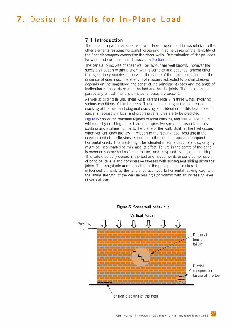
7.1 IntroductionThe force in a particular shear wall will depend upon its stiffness relative to theother elements resisting horizontal forces and in some cases on the flexibility ofthe floor diaphragms connecting the shear walls. Determination of design loadsfor wind and earthquake is discussed in Section 5.1.The general principles of shear wall behaviour are well known. However thestress distribution within a shear wall is complex and depends, among otherthings, on the geometry of the wall, the nature of the load application and thepresence of openings. The strength of masonry subjected to biaxial stressesdepends on the magnitude and sense of the principal stresses and the angle ofinclination of these stresses to the bed and header joints. The inclination isparticularly critical if tensile principal stresses are present.As well as sliding failure, shear walls can fail locally in three ways, involvingvarious conditions of biaxial stress. These are crushing at the toe, tensilecracking at the heel and diagonal cracking. Consideration of this local state ofstress is necessary if local and progressive failures are to be predicted.Figure 6 shows the potential regions of local cracking and failure. Toe failurewill occur by crushing under biaxial compressive stress and usually causessplitting and spalling normal to the plane of the wall. Uplift at the heel occurswhen vertical loads are low in relation to the racking load, resulting in thedevelopment of tensile stresses normal to the bed joint and a consequenthorizontal crack. This crack might be tolerated in some circumstances, or tyingmight be incorporated to minimise its effect. Failure in the centre of the panelis commonly described as ‘shear failure’, and is typified by diagonal cracking.This failure actually occurs in the bed and header joints under a combinationof principal tensile and compressive stresses with subsequent sliding along thejoints. The magnitude and inclination of the principal tensile stress isinfluenced primarily by the ratio of vertical load to horizontal racking load, withthe ‘shear strength’ of the wall increasing significantly with an increasing levelof vertical load.
22
7 . Des i g n o f Wa l l s f o r I n -P l a n e L o ad
Figure 6. Shear wall behaviour
Racking force
Diagonaltensionfailure
Biaxialcompressionfailure at the toe
Tension cracking at the heel
Vertical Force
CBPI Manual 4 : Design of Clay Masonry, First published March 1999

7.2 Shear wall designDesign of shear walls in accordance with AS 3700 uses the shear capacity ofthe masonry, determined from a Coulomb-type equation:
.......................................................................(7)
Where–Vd = The design shear force.
φ = Capacity reduction factor (0.6 for shear in unreinforced masonry).
ƒ’ms = Characteristic shear strength of the masonry (see Section 4.3).
Adw = Bedded area.
kv = Shear factor (0.3 for bed joints in clay masonry).
ƒd = Simultaneously-acting design compressive stress on the bed joint (notgreater than 2 MPa) – based on the non-removable dead load andtaken as 80 per cent of the full dead load.
The first term represents the shear bond strength of the section and the secondterm is the shear friction strength.For earthquake loading, the shear design equation becomes –
..................................................................(8)
Where –ƒde = The design compressive stress on the bed joints under ‘gravity load’.
The other symbols are as before.The difference with this expression is that the superimposed compressivestress providing the friction component is derived using the same gravity loadthat is used to calculate the earthquake (inertia) force. That is, the loadconsidered is the dead load plus a proportion of the live load (see AS 1170.4).The friction component is further reduced by 10 per cent to allow for upwardacceleration that might be present in an earthquake.As well as checking for shear failure on the bed joints using the aboveexpressions, it is necessary to check for the possibility of local compressivefailure at the toe of the wall. Crushing under compressive stresses can bechecked using the appropriate parts of AS 3700, using the compressivestrength of the material. If cracking occurs at the heel, this loss of sectionshould be taken into account in calculating the compressive capacity at the toe.At bedding planes containing damp-proof course membranes and at junctionswith other materials such as a concrete slab, the characteristic shear strengthis usually zero, although AS 3700 does include provision for obtaining valuesby test. When the strength is zero, the resistance is provided solely by friction.Values for the shear factor kv are provided in AS 3700 for various membranesand interfaces and apply to both wind loading situations and reversingearthquake load situations. Shear capacity on these planes must be checked(see Section 8.4).A typical example of shear wall design is shown in Section 9.6.
ƒ’ dwdevdwmsd AƒkAV 9.0+≤φ
ƒ’ dwdvdwmsd AƒkAV +≤ φ
23
Unless major openings ordiscontinuities are present, none ofthese local failures will causecollapse of the wall, although itscapacity might be impaired. Wallssubjected to seismic loading willprogressively degrade with repeatedload reversal as all or some of thesefailures occur in various locationsdepending on the direction ofloading. In some cases of cyclicreversing load, a wall will rock on itsbase as uplift occurs alternately ateach end of the wall. This maycorrespond to gradual shedding ofbricks from the tension end orprogressive local crushing in thecompression region (or bothsimultaneously). Because of thisprocess, and the possibility ofprogressive diagonal failure,unreinforced masonry shear wallshave some capacity for energyabsorption. For walls with majoropenings, significant distress andfailure can also occur in the masonrypiers between openings.The presence of discontinuities in thewall, such as damp-proof courses,slip joints and interfaces with othermaterials such as concrete slabs,provide potential slip planes wherefailure can occur.From a practical point of view, localfailure may have implications forserviceability, but overall failure ofthe wall is the main interest.Consequently, design rules for ‘shearstrength’ have been formulated fromracking tests on masonry panels andthe observed performance of thepanels at failure. This has resulted ina simple relationship expressed inthe form of a Coulomb criterion interms of the average shear andcompressive stresses in the wall.
CBPI Manual 4 : Design of Clay Masonry, First published March 1999

8.1 IntroductionThe bulk of the design provisions in AS 3700 relate to overall structuralbehaviour. However most failures are due to inadequate detailing and design ofjoints, wall ties and connections. The importance of correct attention todetailing for masonry structures cannot be over-emphasised.Since masonry is a brittle material with limited tensile strength, it must besupported by suitable tying systems to keep the flexural stresses withinacceptable limits. Wall ties are used to connect non-loadbearing veneer wallsto a structural backup and allow the leaves of cavity walls to share in resistingthe applied loads. Various types of connectors are used to attach masonrywalls to structural frames and across joints.The earthquake loading code AS 1170.4 requires all roofs to be positivelyattached with a system capable of transmitting a horizontal force of 5 per centto 7.5 per cent of the gravity load (depending on the category). Many of thetraditional wind hold-down details (such as strapping connections) areinadequate for this purpose.The following sections cover design of wall ties and connectors and the designto resist seismic forces of slip joints and joints containing membranes.
8.2 Wall tie designUnlike the previous version of AS 3700, the 1998 edition contains rationalprovisions for design of wall ties. It no longer gives deemed-to-satisfy spacingsfor strength. The overall maximum spacings are 600 mm horizontally andvertically and the first row of ties is required to be within 250 mm from anyedge. These requirements are primarily to ensure a satisfactory distribution ofties in the wall. They are set out in AS 3700 Clause 4.10.As well as satisfying the overall limits on spacings, the ties must be designed toresist the applied forces. A full analysis to determine the tie forces, thatconsiders the properties of the masonry (before and after cracking), thestructural backup and the ties themselves, is complex. AS 3700 deals with thefundamental difference in behaviour between veneer and cavity walls byproviding deemed-to-satisfy design forces. For veneer walls with flexible backup,the design force for each tie is 20 per cent of the total tributary load on avertical line of ties. For veneer walls with stiff backup, the design force for eachtie is 1.3 times the tributary load on the tie. For cavity walls, the design force isequal to the tributary load on the tie. However if a cavity wall has only the innerleaf supported, it must be designed as a veneer wall with stiff backup, and istherefore subject to the more stringent requirements for tie forces.
24
8. Des ign o f Wal l Ties , Connecto rs and Jo in ts
ConstructionTension Compression
Light duty Medium duty Heavy duty Light duty Medium duty Heavy duty
Veneer with flexible backup(2.4 m wall height) 0.94 1.88 4.69 1.09 2.19 5.63
Veneer with stiff backup 0.58 1.15 2.88 0.67 1.35 3.46
Cavity wall (both leaves supported) 0.75 1.50 3.75 0.88 1.75 4.50
Table 4. Maximum wall pressures (kPa) for Type A ties at 600 mm centres
CBPI Manual 4 : Design of Clay Masonry, First published March 1999

An additional requirement, inconsideration of the particularbehaviour of veneer walls on flexiblebackup, is that the top of a wallshould have double the number ofties required elsewhere in the wall.To satisfy this requirement, it mightbe necessary to spread the top row ofties across two adjacent bed joints,within 250 mm of the top of thewall. This requirement for additionalties also applies immediately aboveand below the plane of a horizontalfloor support when the veneer iscontinuous past the support.The number of ties should also bedouble in line with the intersection ofan internal wall support, both forcavity and veneer walls. This isbecause the additional supportstiffness will attract more of thelateral force than would otherwise becarried by the ties.Table 4 shows the maximum wallpressures, calculated using theAS 3700 design forces, for Type Aties spaced at 600 mm in bothdirections. For a veneer wall with aflexible backup, the maximumpressure depends on the wall heightand values are only shown for a2.4 m high wall. Strength design ofthe masonry might result in lowerwall capacities than those shown inthe table.In all situations, it is essential thatties be properly installed. They willnot perform to their full rated strengthunless they are properly embedded inthe mortar joints and properlyattached to the frame or backup (forveneer walls). They must also beinstalled in the correct orientationand without a backward slope, sothat they shed water properly to theoutside of the wall.Typical examples of wall tie designare shown in Sections 9.4 and 9.5.
8.3 Design of connectorsConnectors used to tie masonry wallsto frames and other supportingelements must be designed to resist125 per cent of any calculated loadnormal to the plane of the wall. Theminimum level of forces is specifiedby AS 3700 in Clauses 2.6.3 and
2.6.4. When the forces arise from earthquake action, the calculated horizontalforce must similarly be increased by a factor of 1.25 (see AS 3700 ClauseA3.5). This applies to non-structural as well as structural components.Characteristic strength values for these connectors should be provided by themanufacturer, after determination in accordance with AS 2975. Connectorsmust also comply with the durability requirements (see Section 8.5). Specialconnectors are available for control joints, where they limit movement in thedirection normal to the plane of the wall while allowing movement in the planeof the wall caused by shrinkage or expansion.Where monolithic structural action is required across a vertical interfacebetween two leaves of a solid masonry wall, or between a masonry wall and asupporting member, it must be designed in accordance with AS 3700 Clause4.11. If ties are used they must be rated at least medium duty, spaced at nomore than 200 mm horizontally and 300 mm average (400 mm maximum)vertically. The vertical joint must be filled with mortar. Other connectors ofequivalent strength can be used within the same spacing limits.A special case occurs for diaphragm walls and walls of geometric section,where shear forces are often of much larger magnitude. For these cases,connectors across a vertical interface in masonry are designed in accordancewith AS 3700 Clause 7.5.3. This clause provides equations for steelconnectors of rectangular and circular cross-sections, based on the dimensionsand the yield stress of the steel. These properties should be provided by themanufacturer. For the shear strength of connectors between masonry and otherstructural members, the manufacturer should provide characteristic strengthsdetermined by test.
8.4 Seismic design of slip joints and joints containing membranes
Slip joints are commonly placed between the edges of concrete slabs and thetops of the masonry walls on which they sit, to permit differential movementfrom sources such as shrinkage. These joints usually consist of two sheets ofgalvanised steel with a layer of grease between, or a double layer of damp-proof course material. In conditions of earthquake loading, these joints arelikely to be required to transmit shear forces from the floor slab to the wall andtheir shear capacity under transient loading is therefore important.Damp-proof courses are used at the bases of walls to prevent moisture rising.They are usually formed by embedding a layer of embossed polythene or light-gauge aluminium sheet with bitumen or polythene coating in the mortar joint.Recommended good practice is to place the damp-proof membrane within themortar joint, rather than sitting it on the masonry units and placing the mortaron top. However this is often not done and there is some evidence that thebest performance under serviceability conditions comes from the damp-proofcourse material being placed directly on the masonry units. These joints arealso usually required to transmit shear forces under earthquake loading andtherefore must have some shear resistance.The earthquake loading code AS 1170.4 requires that, for general structures ofdesign category B, walls must be restrained at each floor level where the flooris relied on to provide lateral support to the wall. This provision of the codewas modified in Amendment 1 from the previous requirement that positiveanchors should be provided at each floor. It is therefore now possible to rely onthe friction capacity of the wall/floor connection to provide the necessaryrestraint. Anchors must still be used to connect the roof to the walls and toconnect both roofs and floors for design category C, D and E structures.Domestic structures also require positive connections at intermediate floorlevels. Typical roof connection details are shown in Section 11.
25CBPI Manual 4 : Design of Clay Masonry, First published March 1999

The serviceability requirements for damp-proof course membranes and slipjoints to prevent distress in the masonry seem to conflict with the requirementfor shear transfer under earthquake load conditions. It is thus an importantmatter of design to ensure that the joints have sufficient freedom toaccommodate the serviceability requirements while having sufficient frictioncapacity to provide the shear transfer.AS 3700 uses the Coulomb-type shear equation (see Section 7.2) with a shearfactor kv. For the joints being considered here, the shear bond strength ƒ’ms iszero and the equation for earthquake loading reduces to the simple frictionequation –
...................................................................................(9)
Where –kv = Shear factor
ƒde = The design compressive stress under ‘gravity load’ (see Section 7.2)
Adw = Bedded area
This equation applies to both in-plane and out-of-plane shear. Values of kv
have been investigated experimentally for membrane-type damp-proof coursesunder static loading15 and dynamic loading16. Design values are given inAS 3700 Table 3.3 as 0.3 for bitumen-coated or embossed polyethylene and0.15 for polyethylene-coated and bitumen-coated aluminium. For properlydesigned slip joints using a greased sandwich of metal sheets, the appropriatevalue of shear factor is zero, meaning that these joints cannot be relied upon totransmit shear forces under earthquake loading.
8.5 Durability of ties and connectorsAs pointed out above, ties and connectors are structural components and theirintegrity must be maintained for the life of the structure. When ties andconnectors corrode they are usually hidden in the wall and the damage doesnot become evident until it is advanced. The consequences then are severe.The cost of replacing corroded ties and connectors is vastly greater than theincremental cost of providing enhanced protection when a structure is firstbuilt. Designers should consider this carefully.All ties and connectors used with masonry are required to meet durabilityrequirements set out in AS 3700. These requirements are expressed in termsof a classification of exposure environments, ranging from mild to severemarine, and explanatory material is given in AS 3700 Appendix E. Theaccessories are given a rating from R0 to R5, depending on their materials andother characteristics, and a given exposure environment requires anappropriate durability rating. Pending completion of a revision of the standardfor ties and accessories AS 2699, the performance requirements and deemed-to-satisfy provisions for durability of ties and connectors are given in AS 3700Appendix F.There are many reports of ties deteriorating markedly after only a short time inthe structure, the most notable recent example being after the Newcastleearthquake17. In recent years, stainless steel ties have become more commonand polymer ties have been developed. The revised version of AS 2699 willcontain clearly stated performance requirements and a method of test forcorrosion resistance of metal ties. These measures, combined with anincreased awareness by designers of the importance of tie durability, shouldlead to fewer problems in the future.
dwdevd AƒkV 9.0≤
26CBPI Manual 4 : Design of Clay Masonry, First published March 1999

9.1 One-way vertical bendingExample: Design a section of wall 2 m wide, spanning between top andbottom supports at 2.7 m spacing, carrying no vertical load and an appliedlateral load of 0.5 kPa.
Procedure using AS 3700 (Clause 7.4.2) –Bending moment:
For a single leaf of 110 mm units, fully bedded –
Density for clay masonry = 0.19 kN/m2 per 10 mm thickness (AS 1170.1).Therefore, compressive stress at mid-height due to self-weight (based on 80 per cent dead load) –
Vertical bending capacity –
= 0.28 kN.m permetre width
For two leaves of 110 mm masonry (assumed to share the load equally) –Moment capacity = 0.56 kN.m per metre width, which is greater than theapplied bending moment of 0.46 kN.m per metre. ∴ OK
Procedure using the design charts (Chart 10.1) –Assume a leaf thickness of 110 mm.For a height of 2.7 m, the load capacity of a single leaf is 0.28 kPa, so for twoleaves the capacity is 0.56 kPa. ∴ OK
9.2 One-way horizontal bendingExample: Design a section of wall spanning horizontally 2.4 m betweensupports, for an applied lateral load of 0.7 kPa.
Procedure using AS 3700 (Clause 7.4.3) –Bending moment –
For a single leaf of 230 mm x 110 mm x 76 mm units, fully bedded –
(see Example 9.1),
and Zu, Zp are equal to Zd for full perpends and no joint raking.
Perpend spacing factor kp is the lesser of (see AS 3700 Clause 7.4.3.4) –
= 1.0
1.0 and 76
110 and
110110
==u
p
u
p
h
s
t
s
widthmetreper mm 1002.2 36×=dZ
widthmetreper kN.m50.08
4.27.08
22
=×
==wL
M dh
[ ] 666 101002.2021.01002.22.00.16.0 −×××+××××=
dddmtmtcv ZƒZkM += ƒ’φ
( )[ ] 0.021 MPa
1000110100035.11119.08.0
=×
××××=dƒ
widthmetreper mm 1002.26
11010006
3622
×=×
==bt
Zd
widthmetreper kN.m46.08
7.25.08
22
=×
==wL
M dv
27
9 . Wor k ed Examp l e s
0
600
1200
1800
2400
3000
3600
0 0.5 1 1.5 2 2.5 3
Load Capacity (kPa)
Hei
ght
(mm
)
190 mm
90 mm
110 mm
CBPI Manual 4 : Design of Clay Masonry, First published March 1999
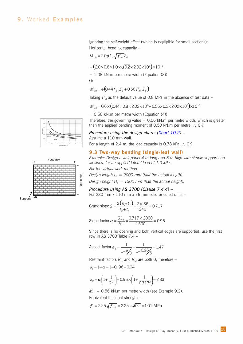
9 . Wor k ed Examp l e s
Ignoring the self-weight effect (which is negligible for small sections):Horizontal bending capacity –
= 1.08 kN.m per metre width (Equation (3))Or –
Taking ƒ’ut as the default value of 0.8 MPa in the absence of test data –
= 0.56 kN.m per metre width (Equation (4))Therefore, the governing value = 0.56 kN.m per metre width, which is greaterthan the applied bending moment of 0.50 kN.m per metre. ∴ OK
Procedure using the design charts (Chart 10.2) –Assume a 110 mm wall.For a length of 2.4 m, the load capacity is 0.78 kPa. ∴ OK
9.3 Two-way bending (single-leaf wall)Example: Design a wall panel 4 m long and 3 m high with simple supports onall sides, for an applied lateral load of 1.0 kPa.For the virtual work method –Design length Ld = 2000 mm (half the actual length).
Design height Hd = 1500 mm (half the actual height).
Procedure using AS 3700 (Clause 7.4.4) –For 230 mm x 110 mm x 76 mm solid or cored units –
Crack slope
Slope factor
Since there is no opening and both vertical edges are supported, use the firstrow in AS 3700 Table 7.4 –
Aspect factor
Restraint factors Rf1 and Rf2 are both 0, therefore –
Mch = 0.56 kN.m per metre width (see Example 9.2).
Equivalent torsional strength –
= 01 MPa.12.025.225.2 =×=mttƒ’ ƒ’
k
k
04.096.0111 =−=−= α
83.2717.01
196.01
1222 =
+×=
+=
Gα
47.13
96.01
1
31
1=
−=
−=
αƒa
96.01500
2000717.0=
×==
d
d
HGL
α
( )717.0
2408622
=×=++
=ju
ju
tlth
G
( ) 666 101002.22.056.01002.28.044.06.0 −××××+××××=chM
( )pmtuutch ZZM 56.044.0 += φ ƒ’ƒ’
dmtpch ZkM 0.2 φ=
( ) 66 101002.22.00.16.00.2 −××××××=
ƒ’
28
0
1200
2400
3600
4800
6000
7200
0 0.5 1 1.5 2 2.5 3
Load Capacity (kPa)
Leng
th (
mm
)
90 mm
110 mm
190 mm
CBPI Manual 4 : Design of Clay Masonry, First published March 1999
Height factor –
Since tu = 110 mm > B, the equivalent torsional section modulus –
Diagonal moment capacity –
The wall load capacity is therefore –
,
which is greater than the applied load of 1.0 kPa. ∴ OK
Procedure using the design charts –Assume a 110 mm wall, therefore use Chart 10.3.1 for four edges supported.For a design length of 2,000 mm and design height of 1,500 mm, the loadcapacity is between the curves for 1.0 kPa and 1.5 kPa. Interpolate a value of1.1 kPa ∴OK
9.4 Veneer wallExample: Design a single-storey masonry veneer wall 2.7 m high supported ona timber frame. The applied lateral load is 1.5 kPa suction on the wall. Assumeties at 600 mm centres in both directions.Design tie force based on 20 per cent of the load on the tributary area for a lineof ties –
Capacity reduction factor = 0.9 (AS 3700 Table 4.1).Load capacity for medium duty ties in tension = 0.60 kN (AS 3700 Table 3.5).
∴Tie capacity OK
The top row of ties must be within 250 mm of the top of the veneer (AS 3700Clause 4.10) and spaced at an average of 300 mm horizontally. This can beachieved by placing two ties at each stud (600 mm centres), either in the samebed joint or spread across two adjacent bed joints within 250 mm of the edge.Ties in the remainder of the wall are spaced at 600 mm in both directions.Provided the tie spacing complies with AS 3700, the veneer skin itself willrequire no further design.
9.5 Cavity wallExample: Design a cavity wall 3 m long and 3 m high for a multi-storeybuilding. The inner leaf is tied to a structural frame on all four sides and theouter leaf is supported on shelf angles attached to the spandrels. The appliedload is 0.5 kPa internal suction and 1.0 kPa external pressure.Only the inner leaf is supported, so design as veneer on a stiff backup(AS 3700 Clause 7.8.4).
kN 0.54 0.60.9 =×=
tensionkN 0.49 5.16.07.220.0 =×××=tdF
( ) kPa 11 .153.082.256.004.00.2
47.12)(
22212
=×+××
=+= cdch
d
ƒ MkMkL
aw
( ) lengthcrack metreper kN.m 53.010100087801.16.0 6 =××××== −ttcd ZM φ ƒ’
( )( )( )2
22
18.13
2Gtl
Bt
tBZ ju
u
ut ++
+=
( )( )( ) lengthcrack mmper mm 878717.0110230
9.698.11103
1109.692 3222
=++×+×
××=
mm 9.69717.01
86
1 22=
+=
+
+=
G
thB ju
29
0
1000
2000
3000
4000
5000
6000
7000
8000
0 1000 2000 3000 4000 5000
( )
Des
ign
Hei
ght
Hd
(mm
)
4.4 kPa 2.2 kPa 1.5 kPa 1.0 kPa 0.7 kPa 0.5 kPa3.3 kPa
CBPI Manual 4 : Design of Clay Masonry, First published March 1999
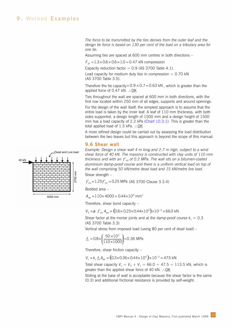
The force to be transmitted by the ties derives from the outer leaf and thedesign tie force is based on 130 per cent of the load on a tributary area forone tie.Assuming ties are spaced at 600 mm centres in both directions –
Capacity reduction factor = 0.9 (AS 3700 Table 4.1).Load capacity for medium duty ties in compression = 0.70 kN (AS 3700 Table 3.5).
Therefore the tie capacity , which is greater than theapplied force of 0.47 kN. ∴OK
Ties throughout the wall are spaced at 600 mm in both directions, with thefirst row located within 250 mm of all edges, supports and around openings.For the design of the wall itself, the simplest approach is to assume that theentire load is taken by the inner leaf. A leaf of 110 mm thickness, with bothsides supported, a design length of 1500 mm and a design height of 1500mm has a load capacity of 2.2 kPa (Chart 10.3.1). This is greater than thetotal applied load of 1.5 kPa. ∴OK
A more refined design could be carried out by assessing the load distributionbetween the two leaves but this approach is beyond the scope of this manual.
9.6 Shear wallExample: Design a shear wall 4 m long and 2.7 m high, subject to a windshear force of 40 kN. The masonry is constructed with clay units of 110 mmthickness and with an ƒ’mt of 0.2 MPa. The wall sits on a bitumen-coatedaluminium damp-proof course and there is a uniform vertical load on top ofthe wall comprising 50 kN/metre dead load and 15 kN/metre live load.Shear strength –
(AS 3700 Clause 3.3.4)
Bedded area –
Therefore, shear bond capacity –
Shear factor at the mortar joints and at the damp-proof course kv = 0.3(AS 3700 Table 3.3)Vertical stress from imposed load (using 80 per cent of dead load) –
Therefore, shear friction capacity –
Total shear capacity Vd = V0 + V1 = 66.0 + 47.5 = 113.5 kN, which isgreater than the applied shear force of 40 kN. ∴OK
Sliding at the base of wall is acceptable because the shear factor is the same(0.3) and additional frictional resistance is provided by self-weight.
( ) kN 5.47101044.036.03.0 361 =××××== −
dwdv AƒkV
ƒ 0.36 MPa 10001101050
8.03
=
××
×=d
( ) kN 0.66101044.025.06.0’ 360 =××××== −
dwms AƒV φ
26 mm 1044.04000110 ×=×=dwA
’msƒ MPa 25.0’25.1 == mtƒ
kN 0.63 0.70.9 =×=
0.47 kN compression 0.16.06.03.1 =×××=tdF
30
9 . Wor k ed Examp l e s
CBPI Manual 4 : Design of Clay Masonry, First published March 1999
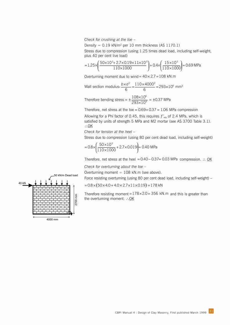
Check for crushing at the toe –Density = 0.19 kN/m2 per 10 mm thickness (AS 1170.1)Stress due to compression (using 1.25 times dead load, including self-weight,plus 40 per cent live load)
Overturning moment due to wind
Wall section modulus mm3
Therefore bending stress
Therefore, net stress at the toe compression
Allowing for a Phi factor of 0.45, this requires ƒ’mb of 2.4 MPa, which issatisfied by units of strength 5 MPa and M2 mortar (see AS 3700 Table 3.1).∴OK
Check for tension at the heel –Stress due to compression (using 80 per cent dead load, including self-weight)
Therefore, net stress at the heel compression. ∴ OK
Check for overturning about the toe –Overturning moment = 108 kN.m (see above).Force resisting overturning (using 80 per cent dead load, including self-weight) –
Therefore resisting moment and this is greater thanthe overturning moment. ∴OK
kN.m 3560.2178 =×=
( ) kN 17819.0117.20.40.4508.0 =×××+××=
MPa 03.037.040.0 =−=
MPa 40.0019.07.210001101050
8.03
=
×+
××
×=
MPa 06.137.069.0 =+=
MPa 37.01029310108
6
6
±=××
±=
622
1029364000110
6×=
×=
×=
db
kN.m 1087.240 =×=
MPa 69.010001101015
4.01000110
101119.07.2105025.1
333
=
××
×+
×
×××+××=
31CBPI Manual 4 : Design of Clay Masonry, First published March 1999

Limitations for all charts:• They apply to single-leaf walls without engaged piers.• No superimposed compression is taken into account.• No joint raking is assumed.• f’mt is assumed to be 0.2 MPa (AS 3700 default).
• f’ut is assumed to be 0.8 MPa (AS 3700 default).
• 30 mm face-shell bedding is assumed for the 190 mm units.• Robustness cut-offs for one-way bending are for other than slab loading;
robustness for two-way bending should be checked separately.• All supports are simple (without rotational restraint) unless otherwise
indicated.
32
1 0 . Des i g n Cha r t s
Index10.1 One-way vertical bending ......................................................................3310.2 One-way horizontal bending ..................................................................3310.3 Two-way bending .................................................................................34
10.3.1 110 mm without openings ......................................................3410.3.2 90 mm without openings ........................................................3510.3.3 110 mm with openings (no rotational restraint at sides) ..............3610.3.4 110 mm with openings (rotational restraint at sides) ..................3810.3.5 90 mm with openings (no rotational restraint at sides) ................4010.3.6 90 mm with openings (rotational restraint at sides) ....................42
CBPI Manual 4 : Design of Clay Masonry, First published March 1999
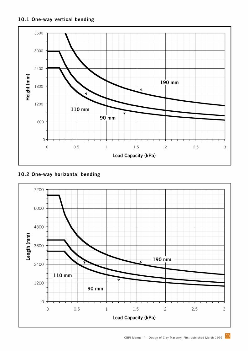
10.1 One-way vertical bending
10.2 One-way horizontal bending
33
0
600
1200
1800
2400
3000
3600
0 0.5 1 1.5 2 2.5 3
Load Capacity (kPa)
Hei
ght
(mm
)
190 mm
90 mm
110 mm
0
1200
2400
3600
4800
6000
7200
0 0.5 1 1.5 2 2.5 3
Load Capacity (kPa)
Leng
th (
mm
)
90 mm
110 mm
190 mm
CBPI Manual 4 : Design of Clay Masonry, First published March 1999
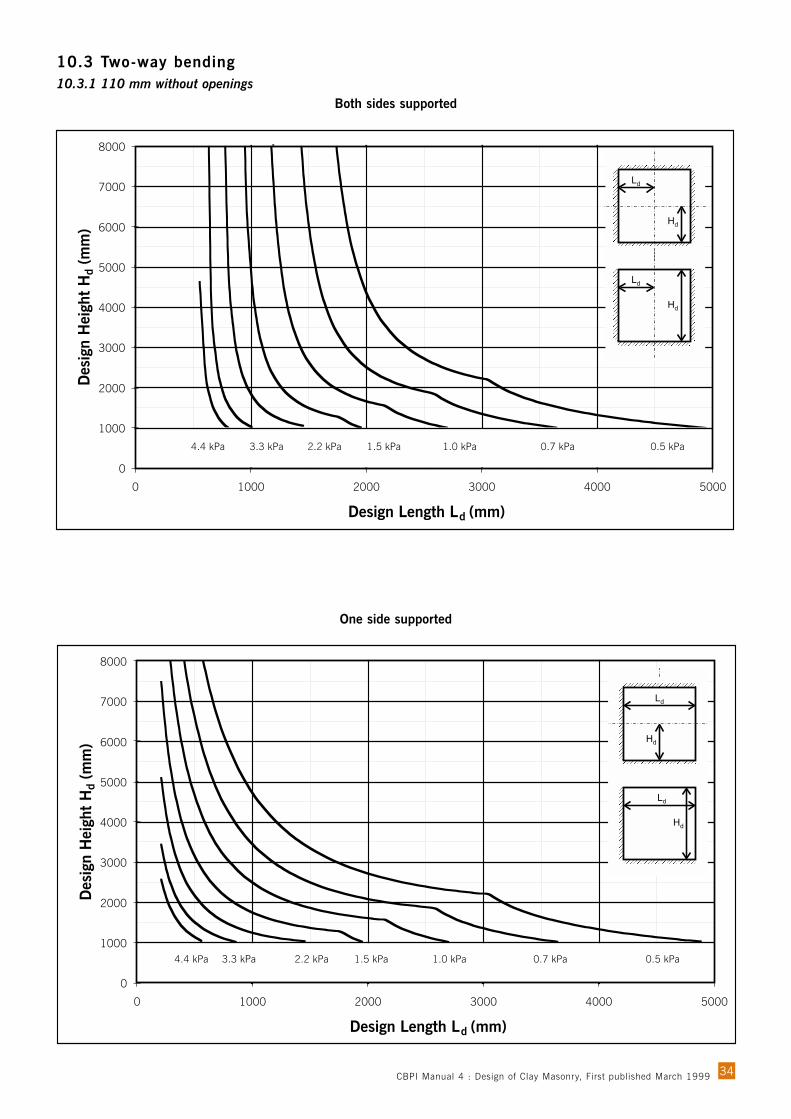
10.3 Two-way bending10.3.1 110 mm without openings
Both sides supported
One side supported
34
0
1000
2000
3000
4000
5000
6000
7000
8000
0 1000 2000 3000 4000 5000
Design Length Ld (mm)
Des
ign
Hei
ght
Hd
(mm
)
4.4 kPa 2.2 kPa 1.5 kPa 1.0 kPa 0.7 kPa 0.5 kPa3.3 kPa
0
1000
2000
3000
4000
5000
6000
7000
8000
0 1000 2000 3000 4000 5000
Design Length Ld (mm)
Des
ign
Hei
ght
Hd
(mm
)
4.4 kPa 2.2 kPa 1.5 kPa 1.0 kPa 0.7 kPa 0.5 kPa3.3 kPa
CBPI Manual 4 : Design of Clay Masonry, First published March 1999
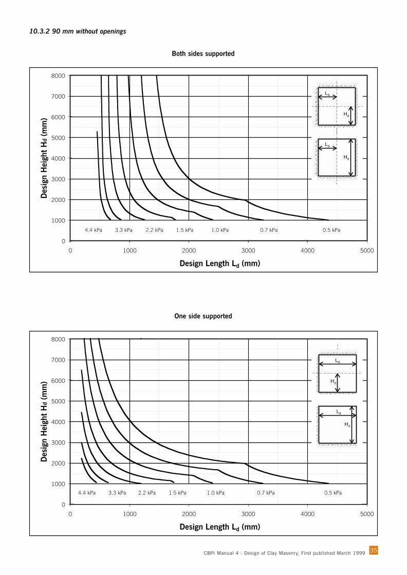
Both sides supported
One side supported
0
1000
2000
3000
4000
5000
6000
7000
8000
0 1000 2000 3000 4000 5000
Design Length Ld (mm)
Des
ign
Hei
ght
Hd
(mm
)
4.4 kPa 2.2 kPa 1.5 kPa 1.0 kPa 0.7 kPa 0.5 kPa3.3 kPa
0
1000
2000
3000
4000
5000
6000
7000
8000
0 1000 2000 3000 4000 5000
Design Length Ld (mm)
Des
ign
Hei
ght
Hd
(mm
)
4.4 kPa 2.2 kPa 1.5 kPa 1.0 kPa 0.7 kPa 0.5 kPa3.3 kPa
35
10.3.2 90 mm without openings
CBPI Manual 4 : Design of Clay Masonry, First published March 1999
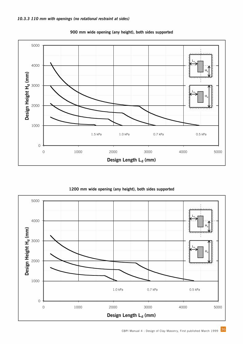
36
10.3.3 110 mm with openings (no rotational restraint at sides)
900 mm wide opening (any height), both sides supported
1200 mm wide opening (any height), both sides supported
0
1000
2000
3000
4000
5000
0 1000 2000 3000 4000 5000
Design Length Ld (mm)
Des
ign
Hei
ght
Hd
(mm
)
1.5 kPa 1.0 kPa 0.7 kPa 0.5 kPa
0
1000
2000
3000
4000
5000
0 1000 2000 3000 4000 5000
Design Length Ld (mm)
Des
ign
Hei
ght
Hd
(mm
)
1.0 kPa 0.7 kPa 0.5 kPa
CBPI Manual 4 : Design of Clay Masonry, First published March 1999
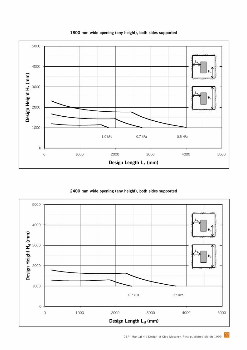
37
1800 mm wide opening (any height), both sides supported
2400 mm wide opening (any height), both sides supported
0
1000
2000
3000
4000
5000
0 1000 2000 3000 4000 5000
Design Length Ld (mm)
Des
ign
Hei
ght
Hd
(mm
)
1.0 kPa 0.7 kPa 0.5 kPa
0
1000
2000
3000
4000
5000
0 1000 2000 3000 4000 5000
Design Length Ld (mm)
Des
ign
Hei
ght
Hd
(mm
)
0.7 kPa 0.5 kPa
CBPI Manual 4 : Design of Clay Masonry, First published March 1999

38
10.3.4 110 mm with openings (rotational restraint at sides)
900 mm wide opening (any height), both sides supported
1200 mm wide opening (any height), both sides supported
0
1000
2000
3000
4000
5000
0 1000 2000 3000 4000 5000
Design Length Ld (mm)
Des
ign
Hei
ght
Hd
(mm
)
4.4 kPa 2.2 kPa 1.5 kPa 1.0 kPa 0.7 kPa 0.5 kPa3.3 kPa
0
1000
2000
3000
4000
5000
0 1000 2000 3000 4000 5000
Design Length Ld (mm)
Des
ign
Hei
ght
Hd
(mm
)
4.4 kPa 2.2 kPa 1.5 kPa 1.0 kPa 0.7 kPa 0.5 kPa3.3 kPa
CBPI Manual 4 : Design of Clay Masonry, First published March 1999

39
1800 mm wide opening (any height), both sides supported
2400 mm wide opening (any height), both sides supported
0
1000
2000
3000
4000
5000
0 1000 2000 3000 4000 5000
Design Length Ld (mm)
Des
ign
Hei
ght
Hd
(mm
)
2.2 kPa 1.5 kPa 1.0 kPa 0.7 kPa 0.5 kPa3.3 kPa
0
1000
2000
3000
4000
5000
0 1000 2000 3000 4000 5000
Design Length Ld (mm)
Des
ign
Hei
ght
Hd
(mm
)
2.2 kPa 1.5 kPa 1.0 kPa 0.7 kPa 0.5 kPa
CBPI Manual 4 : Design of Clay Masonry, First published March 1999
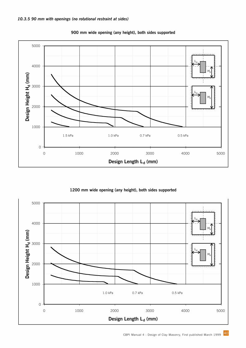
0
1000
2000
3000
4000
5000
0 1000 2000 3000 4000 5000
Design Length Ld (mm)
Des
ign
Hei
ght
Hd
(mm
)
1.0 kPa 0.7 kPa 0.5 kPa
40
10.3.5 90 mm with openings (no rotational restraint at sides)
900 mm wide opening (any height), both sides supported
1200 mm wide opening (any height), both sides supported
0
1000
2000
3000
4000
5000
0 1000 2000 3000 4000 5000
Design Length Ld (mm)
Des
ign
Hei
ght
Hd
(mm
)
1.5 kPa 1.0 kPa 0.7 kPa 0.5 kPa
CBPI Manual 4 : Design of Clay Masonry, First published March 1999

41
1800 mm wide opening (any height), both sides supported
2400 mm wide opening (any height), both sides supported
0
1000
2000
3000
4000
5000
0 1000 2000 3000 4000 5000
Design Length Ld (mm)
Des
ign
Hei
ght
Hd
(mm
)
0.7 kPa 0.5 kPa
0
1000
2000
3000
4000
5000
0 1000 2000 3000 4000 5000
Design Length Ld (mm)
Des
ign
Hei
ght
Hd
(mm
)
0.5 kPa
CBPI Manual 4 : Design of Clay Masonry, First published March 1999
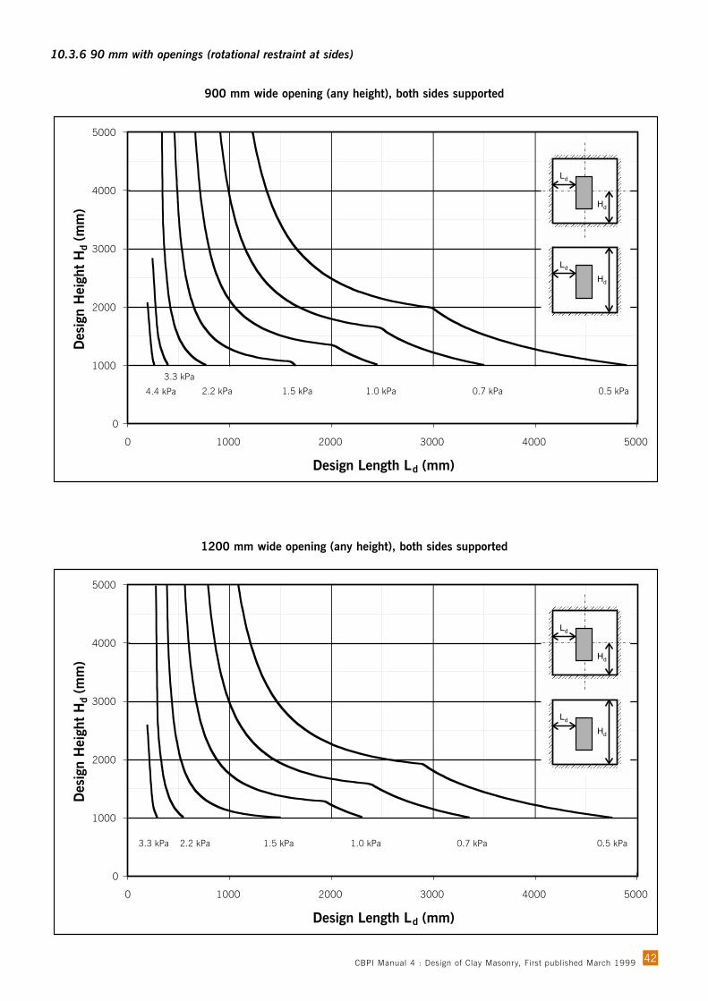
0
1000
2000
3000
4000
5000
0 1000 2000 3000 4000 5000
Design Length Ld (mm)
Des
ign
Hei
ght
Hd
(mm
)
2.2 kPa 1.5 kPa 1.0 kPa 0.7 kPa 0.5 kPa3.3 kPa
0
1000
2000
3000
4000
5000
0 1000 2000 3000 4000 5000
Design Length Ld (mm)
Des
ign
Hei
ght
Hd
(mm
)
4.4 kPa 2.2 kPa 1.5 kPa 1.0 kPa 0.7 kPa 0.5 kPa
3.3 kPa
42
10.3.6 90 mm with openings (rotational restraint at sides)
900 mm wide opening (any height), both sides supported
1200 mm wide opening (any height), both sides supported
CBPI Manual 4 : Design of Clay Masonry, First published March 1999
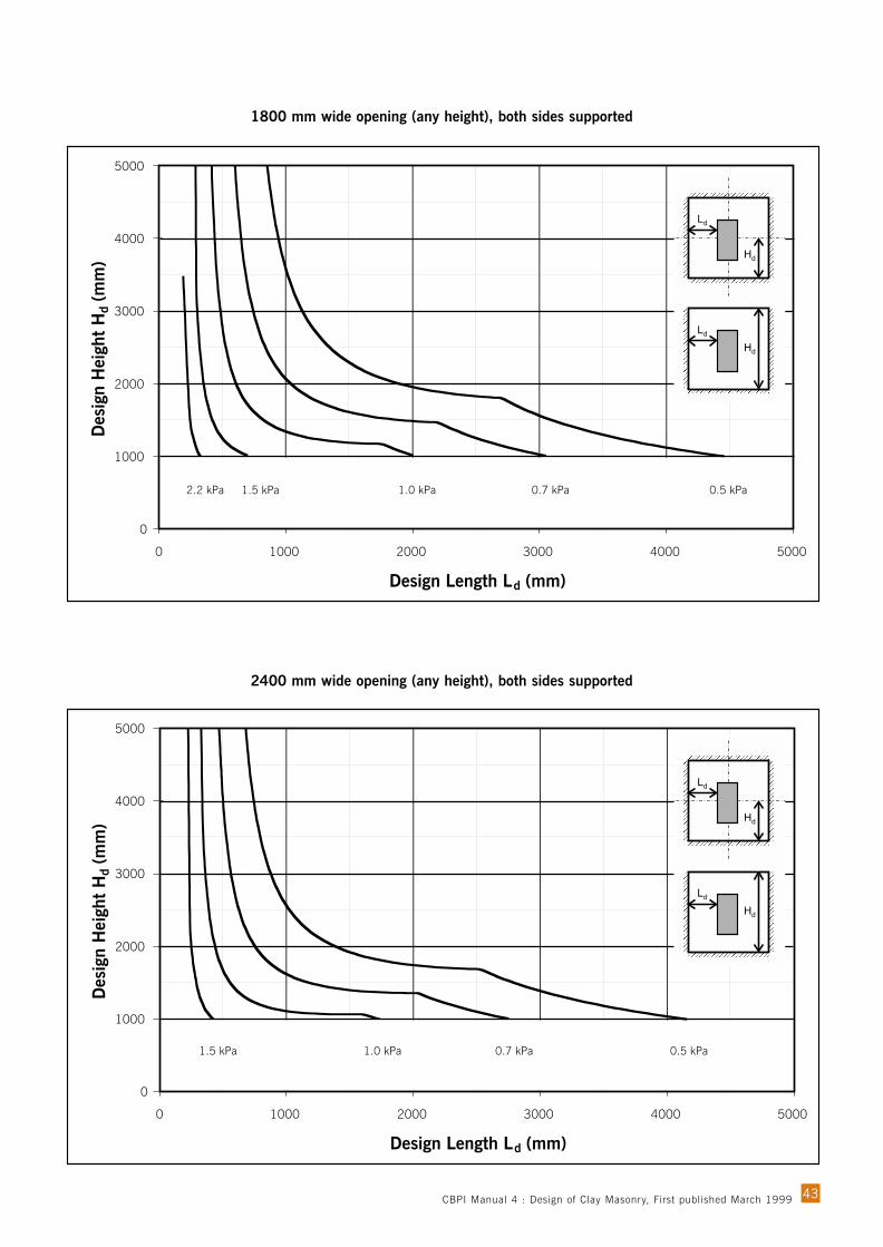
43
1800 mm wide opening (any height), both sides supported
2400 mm wide opening (any height), both sides supported
0
1000
2000
3000
4000
5000
0 1000 2000 3000 4000 5000
Design Length Ld (mm)
Des
ign
Hei
ght
Hd
(mm
)
2.2 kPa 1.5 kPa 1.0 kPa 0.7 kPa 0.5 kPa
0
1000
2000
3000
4000
5000
0 1000 2000 3000 4000 5000
Design Length Ld (mm)
Des
ign
Hei
ght
Hd
(mm
)
1.5 kPa 1.0 kPa 0.7 kPa 0.5 kPa
CBPI Manual 4 : Design of Clay Masonry, First published March 1999

44
Detail 2. Roof tie-down - cavity wall (high wind - not cyclonic)
1 1 . Typ i c a l De t a i l sNote: These details are indicative only and may need to be modified to suit local conditions.
Detail 1. Roof tie-down - cavity wall (low wind)
Strap attached with3 x 30 x 2.8 mmnails to top plate
3 x 30 x 2.8 mmnails to truss/rafter
30 x 0.8 mmgal. straps @max 1200 crs
Strap attached to 10 mmbar embedded 50 mm.min. in each leaf
25 x 1 mm gal. straps @ max. 1200 crs
Embed 50 mm min.
900 mm min.
900 mm min.
CBPI Manual 4 : Design of Clay Masonry, First published March 1999

45
Detail 3. Roof tie-down - cavity wall (earthquake)
25 x 1 mm gal.straps @ max. 1200 crs.
3 x 30 x 2.8 mmnails to truss/rafter
‘TripleGrip’ fastener betweenwall plate and truss/rafter
Strap attached to 10 mmbar embedded 50 mm.min. in each leaf
3 x 30 x 2.8 mmnails to truss/rafter
Gal. strap hooked to reinforcing bar
Starter bar500 mm min.
900 mm min.
M10 chemical anchors atmax. 1500 crs embedment100 mm min.
Detail 4. Roof tie-down - hollow-unit wall (earthquake and high wind)
CBPI Manual 4 : Design of Clay Masonry, First published March 1999

46
Detail 5. Internal wall - ceiling joist perpendicular to wall
Detail 6. Internal wall - ceiling joist parallel to wall
Ceiling joist fixed to topplate with framinganchor and 2 x 30 x 2.8mm nails each end
Top plate fixed with M8chemical anchors at max.1500 mm crs. Minimumembedment 70 mm intobrickwork
Trimmers 75 x 38 F7at 1800 crs.
Joist
Trimmer fixed to top platewith framing anchor and two2.8 mm nails each end
Framing anchor totrimmer and joist with 3 x 30 x 2.8 mm nails
Top plate fixed with M8chemical anchors at max.1500 mm crs. Minimumembedment 70 mm into brickwork
CBPI Manual 4 : Design of Clay Masonry, First published March 1999

47
Detail 7. Cornice support (low wind)
Detail 8. Wall-slab junction
Cornice fixed to joistor glued to ceiling
Two Layers of ‘Alcore’ orsimilar as a slip joint
Flashing
Allowance fortruss deflection
CBPI Manual 4 : Design of Clay Masonry, First published March 1999
48
1 2 . Re f e r e n c e s
1 AS 3700-1998: Masonry Structures, Standards Australia, Sydney, 1998.
2 AS 3700 Supplement 1: Commentary to Masonry in Buildings, Standards Australia, Sydney. (In preparation.)
3 Page, A.W. ‘Unreinforced masonry structures - an Australian overview’, Proceedings of the PacificConference on Earthquake Engineering, The University of Melbourne, Melbourne, Dec. 1995, pp.1-16.
4 AS/NZS 4455:1997, Masonry Units and Segmental Pavers, Standards Australia, Sydney, 1997.
5 AS/NZS 4456:1997, Masonry Units and Segmental Pavers – Methods of Test, Standards Australia, Sydney, 1997.
6 AS 2699-1984: Wall Ties for Masonry Construction, Standards Association of Australia, Sydney, 1984. (Atthe time of publication a revision is in preparation and is expected in 1999.)
7 AS 2975-1987, Accessories for Masonry Construction, Standards Association of Australia, Sydney, 1987.(At the time of publication a revision is in preparation and is expected in 1999.)
8 AS 2904-1986, Damp-proof Courses and Flashings, Standards Association of Australia, Sydney, 1986.
9 AS 1170.4-1993: Minimum Design Loads on Structures, Part 4: Earthquake Loads,Standards Australia, Sydney, 1993.
10 AS 1170.2-1989: SAA Loading Code, Part 2: Wind Loads, Standards Australia, Sydney, 1989.
11 AS 4055-1992: Wind Loads for Housing, Standards Australia, Sydney, 1992.
12 AS 1170.4 Supplement 1-1993: Minimum Design Loads on Structures, Part 4: Earthquake Loads-Commentary, Standards Australia, Sydney, 1993.
13 AS 3826-1998: Strengthening Existing Buildings for Earthquake, Standards Australia, Sydney, 1998.
14 Lawrence, S.J. & Marshall, R.J. ‘The new AS 3700 approach to lateral load design’. Proceedings of theFifth Australasian Masonry Conference, Gladstone, July 1998.
15 Page, A.W. ‘The shear capacity of damp-proof courses in masonry’. Civil Engineering Transactions,Institution of Engineers Australia. CE37(1), Feb. 1995, pp.29-39.
16 Page, A.W. and Griffith, M.C. ‘A preliminary study of the seismic behaviour of slip joints and jointscontaining membranes in masonry structures’. The University of Newcastle, Department of Civil, Surveying& Environmental Engineering Research Report, Dec. 1997.
17 Page, A.W. ‘The design, detailing and construction of masonry - the lessons from the Newcastleearthquake’. Civil Engineering Transactions, Institution of Engineers Australia. CE34(4), Dec. 1992, pp.343-353.
CBPI Manual 4 : Design of Clay Masonry, First published March 1999