Design of Bolt and Nut
41
-
Upload
ra-balamurugan -
Category
Documents
-
view
254 -
download
0
Transcript of Design of Bolt and Nut

7/27/2019 Design of Bolt and Nut
http://slidepdf.com/reader/full/design-of-bolt-and-nut 1/41
7/27/2019 Design of Bolt and Nut
http://slidepdf.com/reader/full/design-of-bolt-and-nut 2/41
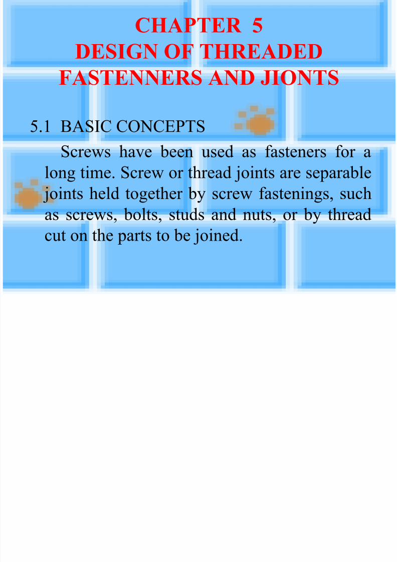
CHAPTER 5
DESIGN OF THREADED
FASTENNERS AND JIONTS
5.1 BASIC CONCEPTS
Screws have been used as fasteners for a
long time. Screw or thread joints are separable
joints held together by screw fastenings, such
as screws, bolts, studs and nuts, or by thread
cut on the parts to be joined.

7/27/2019 Design of Bolt and Nut
http://slidepdf.com/reader/full/design-of-bolt-and-nut 3/41
Screws engage the
threads of nuts or of
other parts.
A nut is a threaded
fastening with internal
thread. It is screwed on
the bolt and is of a
shape designed to be
gripped by a wrench or by hand.
Fig.5.1 Screw (bolt) and nut

7/27/2019 Design of Bolt and Nut
http://slidepdf.com/reader/full/design-of-bolt-and-nut 4/41
5.2 THREAD STANDARDS AND
DEFINITIONS
Fig.5.2 General screw-thread symbols

7/27/2019 Design of Bolt and Nut
http://slidepdf.com/reader/full/design-of-bolt-and-nut 5/41
Where d — the largest diameter of a screw
thread;d1 — minor diameter, i.e. the smallest
diameter of a screw thread;
d2 — mean diameter; p — pitch;
s — lead;
— Thread angle;
h — height of thread engagement;
— lead (or helix) angle.

7/27/2019 Design of Bolt and Nut
http://slidepdf.com/reader/full/design-of-bolt-and-nut 6/41
According to their purpose, screw threads are
classified as:
(1) Fastening threads;
(2) Fastening and sealing threads;
(3) Power threads

7/27/2019 Design of Bolt and Nut
http://slidepdf.com/reader/full/design-of-bolt-and-nut 7/41
Fig.5.3 Principal type of screw threads

7/27/2019 Design of Bolt and Nut
http://slidepdf.com/reader/full/design-of-bolt-and-nut 8/41
5.3 SCREW FASTENINGS
Depending upon the type of screw joint
involved, screw fastenings are classed as:
(1) Screws with nuts, generally called bolts;
(2) Cap screws inserted into tapped holes in the
parts being fastened;
(3) Studs, or stud-bolts, used with nuts and
having threads on both ends.

7/27/2019 Design of Bolt and Nut
http://slidepdf.com/reader/full/design-of-bolt-and-nut 9/41Fig.5.4 Principal types of screw joints

7/27/2019 Design of Bolt and Nut
http://slidepdf.com/reader/full/design-of-bolt-and-nut 10/41
With respect to the shape of their heads, screwfastenings are divided into:
(1) Those in which the head is engaged
externally by a tool (wrench , etc.);(2) Those in which the head is engaged
internally and from the end face;
(3) Those that prevent the screw fasteningfrom turing.

7/27/2019 Design of Bolt and Nut
http://slidepdf.com/reader/full/design-of-bolt-and-nut 11/41
Fig.5.5 Heads of cap screws

7/27/2019 Design of Bolt and Nut
http://slidepdf.com/reader/full/design-of-bolt-and-nut 12/41
Setscrews are
another form of
fastener; the usualuse for them is to
prevent relative
circular motion
between two parts
such as shafts and
pulleys. They may
be used onlywhere the torque
requirements are
low.
Fig.5.7 Applications of setscrews

7/27/2019 Design of Bolt and Nut
http://slidepdf.com/reader/full/design-of-bolt-and-nut 13/41
The types of points of setscrews are follows:
Fig.5.8 Setscrews with various points

7/27/2019 Design of Bolt and Nut
http://slidepdf.com/reader/full/design-of-bolt-and-nut 14/41
The main types of nuts are as follows:
Fig.5.10 Principal types of nuts
7/27/2019 Design of Bolt and Nut
http://slidepdf.com/reader/full/design-of-bolt-and-nut 15/41
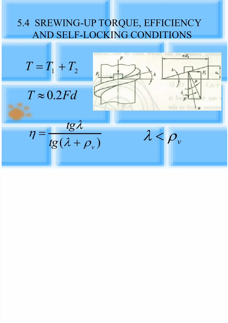
5.4 SREWING-UP TORQUE, EFFICIENCY
AND SELF-LOCKING CONDITIONS
)(v
tg
tg
v
21 T T T
Fd T 2.0

7/27/2019 Design of Bolt and Nut
http://slidepdf.com/reader/full/design-of-bolt-and-nut 16/41
5.5 BOLT TIGHTENING AND INTIAL
TENSION
F
----initial force Fig.5.13 Torque-wrenches
7/27/2019 Design of Bolt and Nut
http://slidepdf.com/reader/full/design-of-bolt-and-nut 17/41
5.6 PREVENTING UNINTENTIONAL
UNSCREWING OF SCREW JOINTS
Locking can be accomplished by the following
measures:(1) By supplementary friction;
(2) by using special locking devices;
(3) by plastic deformation or welding on.

7/27/2019 Design of Bolt and Nut
http://slidepdf.com/reader/full/design-of-bolt-and-nut 18/41
Fig.5.14 Locking devices based on the
application of supplementary friction

7/27/2019 Design of Bolt and Nut
http://slidepdf.com/reader/full/design-of-bolt-and-nut 19/41
Fig.5.15 Locking devices using special
locking elements
7/27/2019 Design of Bolt and Nut
http://slidepdf.com/reader/full/design-of-bolt-and-nut 20/41
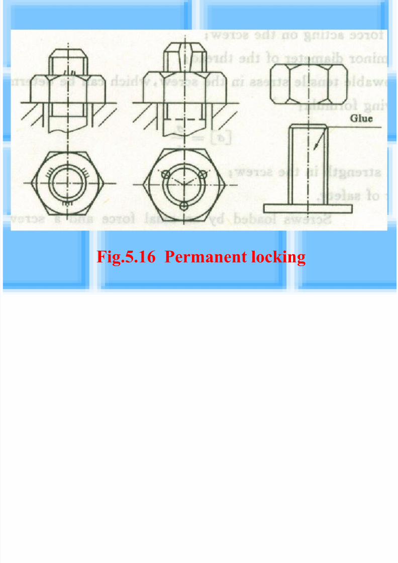
Fig.5.16 Permanent locking

7/27/2019 Design of Bolt and Nut
http://slidepdf.com/reader/full/design-of-bolt-and-nut 21/41
5.7 SCREW AND THREAD ELEMENT
DESIGN FOR STEADY LOADS
1. Screws without aninitial preload
The nominal tensile
stress in the screw is
From which theminor diameter is
Fig.5.17 Hoisting hook
][
4
2
1
d
F
][
41
F d

7/27/2019 Design of Bolt and Nut
http://slidepdf.com/reader/full/design-of-bolt-and-nut 22/41
2. Screws loaded by an
axial force and a
screwing-up torque
The equivalent nomal
stress in a screw due to
tension and torque is
or
Fig.5.18 Bolted joints in
tension
][
4
3.12
1
d
F e
3.1)5.0(33 2222
e

7/27/2019 Design of Bolt and Nut
http://slidepdf.com/reader/full/design-of-bolt-and-nut 23/41
5.8 DESIGN OF SCREW JOINTS SUBJECT
TO LOADS ON THE PLANE OF THE
JOINT
Screw joints of two kinds are employed:
(a) With screws inserted in holes with a
clearance;
(b) With screws fitting into reamed holes
without appreciable clearance.

7/27/2019 Design of Bolt and Nut
http://slidepdf.com/reader/full/design-of-bolt-and-nut 24/41
tu
Fig.5.19 Screw joints subject to loads on
the plane of the joints

7/27/2019 Design of Bolt and Nut
http://slidepdf.com/reader/full/design-of-bolt-and-nut 25/41
1. If screws are installed with a clearance, they
must develop a friction force on the plane of the joint, which exceeds the external shear force.
The required screwing-up force in this case is
The required screw diameter can be calculatedon the basis of the corresponding screwing-upforce.
][
mz
KR F

7/27/2019 Design of Bolt and Nut
http://slidepdf.com/reader/full/design-of-bolt-and-nut 26/41
2. If screws are fitted into reamed holes they are
checked in shear. Then the strength condition of the screw is
][0
p
s
p hd
F
][4
2
0
md
F s
z
R F s

7/27/2019 Design of Bolt and Nut
http://slidepdf.com/reader/full/design-of-bolt-and-nut 27/41
3. joints loaded by the moment T developed
by the forces acting on the plane of the
abutting surfaces of the joint when thescrews are installed with clearance in their
holes
The holding power condition is
z
i
z r
KT
r r r
KT F
1
121 )(

7/27/2019 Design of Bolt and Nut
http://slidepdf.com/reader/full/design-of-bolt-and-nut 28/41
a) b)
Fig.5.21 Joints subject to shearing moments

7/27/2019 Design of Bolt and Nut
http://slidepdf.com/reader/full/design-of-bolt-and-nut 29/41
4. When the screws are installed without
clearance in their holes, the condition of
equilibrium is
According to the condition that the forces
are proportional to the displacements
So the shearing force on the most heavilyloaded screw is:
z sz s s r F r F r F T 2211
z
sz s s
r
F
r
F
r
F
2
2
1
1
8
1
2
1
8541
ii
s s s s
r
Tr F F F F
7/27/2019 Design of Bolt and Nut
http://slidepdf.com/reader/full/design-of-bolt-and-nut 30/41
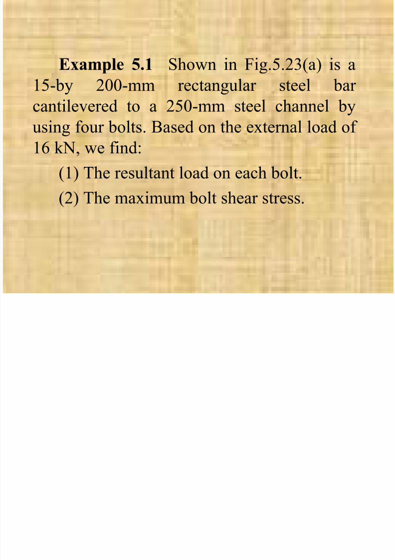
Example 5.1 Shown in Fig.5.23(a) is a15-by 200-mm rectangular steel bar
cantilevered to a 250-mm steel channel by
using four bolts. Based on the external load of
16 kN, we find:
(1) The resultant load on each bolt.
(2) The maximum bolt shear stress.

7/27/2019 Design of Bolt and Nut
http://slidepdf.com/reader/full/design-of-bolt-and-nut 31/41
a) b)
Fig.5.23 Dimentions in millimeters

7/27/2019 Design of Bolt and Nut
http://slidepdf.com/reader/full/design-of-bolt-and-nut 32/41
Slution
(1) The sheer reaction V would pass through Oand the moment reaction T would be about O.
These reactions areV=16kN T=16×425=6800Nm
The distance from the centroid to the center of
each bolt is
The primary shear load per bolt is
The secondary shear forces are equal,kN z
V F v 44
16
kN
r
T
r
Tr F T 7.17
0.964
6800
442
mmr 0.967560 22

7/27/2019 Design of Bolt and Nut
http://slidepdf.com/reader/full/design-of-bolt-and-nut 33/41
The resultants are obtained by using the
parallelogram rule.
FA=FB=21.0kN
FC=FD=13.8kN
(2) Bolts A and B are critical because they carry
the largest shear load.
The shear-stress area is
So the shear tress is
242
0 2274
17
4mm
d A
s
MPa A
F
s
s 51.92227
100.21 3max
5 9 DESIGN OF SCREW JOINTS SUBJECT
7/27/2019 Design of Bolt and Nut
http://slidepdf.com/reader/full/design-of-bolt-and-nut 34/41
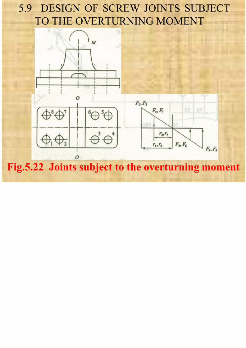
5.9 DESIGN OF SCREW JOINTS SUBJECT
TO THE OVERTURNING MOMENT
Fig.5.22 Joints subject to the overturning moment
7/27/2019 Design of Bolt and Nut
http://slidepdf.com/reader/full/design-of-bolt-and-nut 35/41
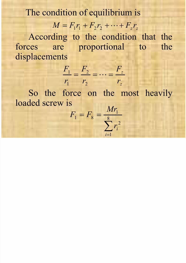
The condition of equilibrium is
According to the condition that theforces are proportional to thedisplacements
So the force on the most heavilyloaded screw is
z z r F r F r F M 2211
z
z
r
F
r
F
r
F
2
2
1
1
8
1
2
181
ii
r
Mr F F

7/27/2019 Design of Bolt and Nut
http://slidepdf.com/reader/full/design-of-bolt-and-nut 36/41
5.10 BOLT TENTION WITH EXTERNALJOINT-SEPARATING FORCE
Fig.5.24 Study of bolt tensile loading

7/27/2019 Design of Bolt and Nut
http://slidepdf.com/reader/full/design-of-bolt-and-nut 37/41
The resultant load on the bolt is
or
The resultant load in the connected members is
Fig. 5.25 is a plot of the force – deflectioncharacteristics.
F F F 1
F K K
K F F
21
1
1
F
K K
K F F
21
22

7/27/2019 Design of Bolt and Nut
http://slidepdf.com/reader/full/design-of-bolt-and-nut 38/41
Fig.5.25 Plot of the force-deflection characteristics

7/27/2019 Design of Bolt and Nut
http://slidepdf.com/reader/full/design-of-bolt-and-nut 39/41
Example 5.2 In Fig. 5.24(c), let K 2=8K 1. If
the preload is F′= 5000N and the external loadis F=5500N, what are the resultant tension in
the bolt and the compression in members?
Slution
The resultant bolt tension is
N K K
K
F K K
K F F
561150008
500011
1
21
11

7/27/2019 Design of Bolt and Nut
http://slidepdf.com/reader/full/design-of-bolt-and-nut 40/41
The resultant compression of the members is
The member s are still in compression , hencethere is no separation of the parts.
N K K
K
F K K
K F F
11155008
85000
11
1
21
22

7/27/2019 Design of Bolt and Nut
http://slidepdf.com/reader/full/design-of-bolt-and-nut 41/41
Homework
5.5; 5.7


![Bolt & Nut Designer Manual [Panchsheel]](https://static.fdocuments.in/doc/165x107/563dbabb550346aa9aa78fe1/bolt-nut-designer-manual-panchsheel.jpg)