Design of a windmill for pumping water · The main objective of our project was to design a...
73
UNIVERSITY OF NAIROBI DEPARTMENT OF MECHANICAL AND MANUFACTURING ENGINEERING FINAL YEAR PROJECT REPORT TITLE: DESIGN OF A WINDMILL FOR PUMPING WATER MACHINI N. MERCYLINE F18/2444/2009 OKERO JULIUS MOKAYA F18/2412/2009 PROJECT SUPERVISOR: PROF. NYANG’AYA J.A You created this PDF from an application that is not licensed to print to novaPDF printer (http://www.novapdf.com)
Transcript of Design of a windmill for pumping water · The main objective of our project was to design a...
UNIVERSITY OF NAIROBI
DEPARTMENT OF MECHANICAL AND MANUFACTURING ENGINEERING
FINAL YEAR PROJECT REPORT
TITLE: DESIGN OF A WINDMILL FOR PUMPING WATER
MACHINI N. MERCYLINE F18/2444/2009
OKERO JULIUS MOKAYA F18/2412/2009
PROJECT SUPERVISOR: PROF. NYANG’AYA J.A
You created this PDF from an application that is not licensed to print to novaPDF printer (http://www.novapdf.com)
i
DECLARATION
We declare that this is our original work and has not been presented for any degree in any other university or institution of learning.
MACHINI N. MERCYLINE F18/2444/2009
…………………………………. DATE………………………….
OKERO JULIUS MOKAYA F18/2412/2009
…………………………………. DATE …………………………
This project is submitted as part of the examination board requirements for the award of the Bachelor of Science degree in Mechanical and Manufacturing Engineering from the University of Nairobi.
Project Supervisor: Prof. Nyang’aya J.A
……………………………………….. DATE…………………………….
You created this PDF from an application that is not licensed to print to novaPDF printer (http://www.novapdf.com)
ii
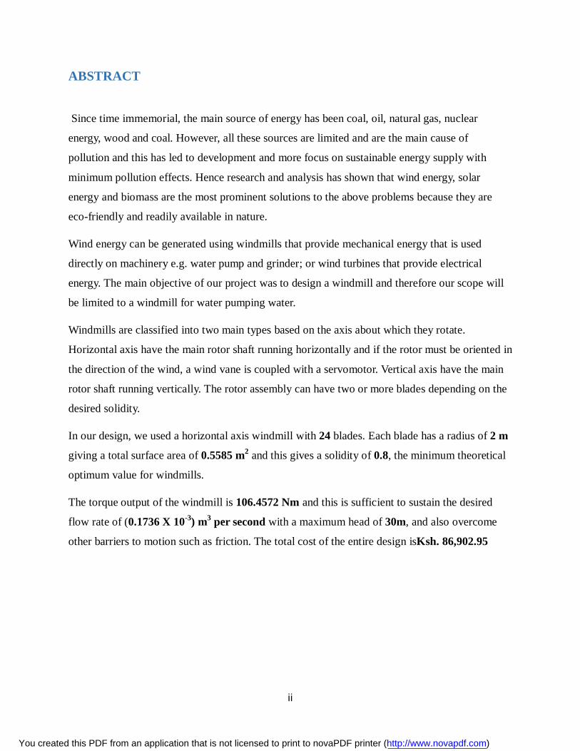
ABSTRACT
Since time immemorial, the main source of energy has been coal, oil, natural gas, nuclear
energy, wood and coal. However, all these sources are limited and are the main cause of
pollution and this has led to development and more focus on sustainable energy supply with
minimum pollution effects. Hence research and analysis has shown that wind energy, solar
energy and biomass are the most prominent solutions to the above problems because they are
eco-friendly and readily available in nature.
Wind energy can be generated using windmills that provide mechanical energy that is used
directly on machinery e.g. water pump and grinder; or wind turbines that provide electrical
energy. The main objective of our project was to design a windmill and therefore our scope will
be limited to a windmill for water pumping water.
Windmills are classified into two main types based on the axis about which they rotate.
Horizontal axis have the main rotor shaft running horizontally and if the rotor must be oriented in
the direction of the wind, a wind vane is coupled with a servomotor. Vertical axis have the main
rotor shaft running vertically. The rotor assembly can have two or more blades depending on the
desired solidity.
In our design, we used a horizontal axis windmill with 24 blades. Each blade has a radius of 2 m
giving a total surface area of 0.5585 m2 and this gives a solidity of 0.8, the minimum theoretical
optimum value for windmills.
The torque output of the windmill is 106.4572 Nm and this is sufficient to sustain the desired
flow rate of (0.1736 X 10⁻³) m3 per second with a maximum head of 30m, and also overcome
other barriers to motion such as friction. The total cost of the entire design isKsh. 86,902.95
You created this PDF from an application that is not licensed to print to novaPDF printer (http://www.novapdf.com)
iii
Contents DECLARATION......................................................................................................................... i
ABSTRACT .............................................................................................................................. ii
LIST OF FIGURES................................................................................................................... vi
LIST OF TABLES .................................................................................................................. viii
ACKNOWLEDGEMENTS....................................................................................................... ix
DEDICATION ............................................................................................................................x
LIST OF ABBREVIATIONS .................................................................................................... xi
1.0 INTRODUCTION .................................................................................................................1
1.1 DEFINITIONS ......................................................................................................................1
1.2 BACKGROUND...................................................................................................................1
1.3 OBJECTIVE .........................................................................................................................2
1.4 PROBLEM STATEMENT ....................................................................................................2
1.5 SCOPE OF DESIGN .............................................................................................................3
2.0 LITERATURE REVIEW ......................................................................................................4
2.1 SITE SELECTION ................................................................................................................4
2.2.1 Advantages of Wind Power .................................................................................................4
2.2.2 Disadvantages of Wind Power ............................................................................................4
2.3 TYPES OF WINDMILLS .....................................................................................................5
2.3.1 Vertical Axis Wind Turbine (VAWT) ..................................................................................5
2.3.1.1 Savonius ..........................................................................................................................5
2.3.1.2 Darrieus ...........................................................................................................................5
2.3.2 Horizontal Axis Wind Turbine (HAWT) .............................................................................6
3.0 THEORY ..............................................................................................................................8
3.1 DEFINITIONS ......................................................................................................................8
You created this PDF from an application that is not licensed to print to novaPDF printer (http://www.novapdf.com)
iv
3.1.1 Power Coefficient Cp ..........................................................................................................8
3.1.2 Swept Area, As ...................................................................................................................8
3.1.3 Tip Speed Ratio, ..............................................................................................................9
3.1.4 Specific Speed of the Windmill...........................................................................................9
3.1.5 Cut in Speed .......................................................................................................................9
3.1.6 Cut out Speed ................................................................................................................... 10
3.1.7 Rated Wind Speed ............................................................................................................ 10
3.1.8 Torque Coefficient, Ct ....................................................................................................... 10
3.1.9 Rotor Solidity ................................................................................................................... 10
3.1.10 Thrust Coefficient CT ...................................................................................................... 11
3.2 WIND POWER DERIVATION ........................................................................................... 12
3.2.1 Wind Power: ..................................................................................................................... 12
3.2.2 Efficiency in Wind Power Extraction ................................................................................ 12
3.2.3 Torque Extracted .............................................................................................................. 13
3.3 EFFICIENCY, POWER AND TORQUE CHARACTERISTICS ......................................... 14
3.3.1 Power – Speed Characteristics .......................................................................................... 14
3.3.2 Torque-Speed Characteristics............................................................................................ 15
3.3.3 Power Coefficient (CP) and Torque Coefficient (CT) against Tip Speed ratio () ............... 15
4. DESIGN................................................................................................................................ 18
4.1 BLADE ............................................................................................................................... 18
4.1.1 Blade Design Consideration ............................................................................................. 18
4.1.2 Calculation of the Rotor Radius ........................................................................................ 24
4.1.3 Final Blade Design ........................................................................................................... 29
4.2 POWER TRANSMISSION MECHANISMS USED ........................................................... 30
4.2.1 Gears ................................................................................................................................ 30
You created this PDF from an application that is not licensed to print to novaPDF printer (http://www.novapdf.com)
v
4.2.1.1 Spur Gears ..................................................................................................................... 32
4.2.1.2 Helical Gears ................................................................................................................. 33
4.2.1.3 Bevel Gears ................................................................................................................... 33
4.2.2 Materials Used in the Manufacture of Gears ..................................................................... 34
4.2.3 Bearings ........................................................................................................................... 36
4.2.3.1 Materials Used in the Manufacture of Bearings.............................................................. 36
4.2.3.2 Types of Bearings .......................................................................................................... 39
4.3 TAIL DESIGN .................................................................................................................... 41
4.3.1 Calculations of Moments .................................................................................................. 42
4.3.1.1 Anticlockwise Moments ................................................................................................ 42
4.3.1.2 Clockwise Moments ...................................................................................................... 44
4.4 RIG DESIGN ...................................................................................................................... 46
4.5 TURNTABLE ..................................................................................................................... 47
4.6 GEAR BOX ........................................................................................................................ 48
5.0 DISCUSSION AND CONCLUSION .................................................................................. 51
5.1 TORQUE DEVELOPED ..................................................................................................... 51
5.2 SHAFT STRESS ANALYSIS.............................................................................................. 51
5.2.1 Moment Generated by the Rotors ..................................................................................... 53
5.3 DESIGN SPECIFICATIONS OF THE WINDMILL............................................................ 54
5.4 BILL OF QUANTITIES ...................................................................................................... 55
5.5 CONCLUSION ................................................................................................................... 56
5.6 RECOMMENDATIONS ..................................................................................................... 56
REFERENCES ......................................................................................................................... 57
APPENDIX 1: Sheet Metal Thickness and British Standard Wire Gauge, SWG ....................... 58
APPENDIX 2: Parts and Assembly Drawings ........................................................................... 59
You created this PDF from an application that is not licensed to print to novaPDF printer (http://www.novapdf.com)
vi
LIST OF FIGURES Figure Page
Fig 2.1: Darrieus Wind Turbine 6
Fig 2.2: Horizontal Axis Wind Turbine 7
Fig 3.1: Illustration of the Wind flow control volumes 12
Fig 3.2: Power of a windmill as a function of rotational speed for various wind speeds. 14
Fig 3.3: Torque of a windmill rotor as a function of the rotational speed for the various wind speeds. 15
Fig 3.4: Graph of the Coefficient of Power (Cp) against the tip-speed ratio () for different windmill and wind turbine design 16
Fig 3.5: A key to the different windmill and wind turbine designs that have been used in the
graphs above 17
Fig 4.1: Illustration of the reaction force that causes thrust 18
Fig 4.2: Illustration of the Bernoulli Effect causing lift (blade cross-section) 19
Fig 4.3: Generator – High Speed and low torque 20
Fig 4.4: Pump – Low Speed and high torque 20
Fig 4.5: Illustration of the leading and trailing edges 20
Fig 4.6: Illustration of the angle of attack 21
Fig 4.7: Illustration of the stall 22
Fig 4.7: An Illustration of the stations 23
Fig 4.8: Illustration of the Radius 23
Fig 4.9: Illustration of the angle of attack (α), setting angle (β) and flow angle (Φ) 23
Fig 4.10: The variation of the setting angle at the root and at the tip 24
Fig 4.11: Illustration of the Chord 24
Fig 4.12: Projected Area of the blade 29
You created this PDF from an application that is not licensed to print to novaPDF printer (http://www.novapdf.com)
vii
Fig 4.13: Nomenclature of gear 31
Fig 4.14: Spur gear 32
Fig 4.15: Helical gear 33
Fig 4.16: Bevel gears 34
Fig 4.17: A rotating shaft, metal contact and the acting forces. 37
Fig 4.18: Needle Roller bearing 39
Fig 4.19: Ball Bearing 39
Fig 4.20: roller bearing 40
Fig 4.21: Illustration of the lift forces on the windmill tail 41
Fig 4.22: Sections of the tail that contribute to the bending moments 44
Fig 4.23: Cross-Sectional View of the turntable design 48
Fig 4.24: Final gear box design 49
Fig 4.25: Gear box cover design 50
Fig 5.1: Main shaft cross section 52
Fig 5.2: The Couple resulting from the rotor assembly 53
You created this PDF from an application that is not licensed to print to novaPDF printer (http://www.novapdf.com)
viii
LIST OF TABLES Table Page
Table 4.1: Typical choices for the tip speed ratio and blade number for pump and generator 19
Table 4.2: Data for some common blade cross-sections 21
Table 4.3: Power losses in a windmill 25
Table 4.4: Density of Air 28
Table 4.5: Efficiencies of various types of gears 34
Table 4.6: Properties of Gears 35
Table 4.7: Selection of bearings 38
Table 4.8: Mild steel properties 47
Table 5.1: Mild steel properties 51
Table 5.2: Final windmill design specifications 54
Table 5.3: Costing of the various windmill components 56
You created this PDF from an application that is not licensed to print to novaPDF printer (http://www.novapdf.com)

ix
ACKNOWLEDGEMENTS
First of all, we would wish to express our sincere gratitude to the Almighty God for giving us the intellect so used in the course of this project.
Special thanks to our project supervisor Prof. Nyang’aya J.A for being instrumental and supportive throughout the course of our project.
Many thanks to the department of Mechanical and Manufacturing Engineering Workshop staff for their assistance and cooperation. Special thanks to the technician Mr. Kuria for his support in the course of the project.
Lastly, we wish to thank the department of Mechanical and manufacturing Engineering for the support and funding of this project to make it successive.
You created this PDF from an application that is not licensed to print to novaPDF printer (http://www.novapdf.com)

x
DEDICATION
We would like to dedicate this project to our families for playing a pivotal role, in not just our project but our education thus far.
You created this PDF from an application that is not licensed to print to novaPDF printer (http://www.novapdf.com)
xi
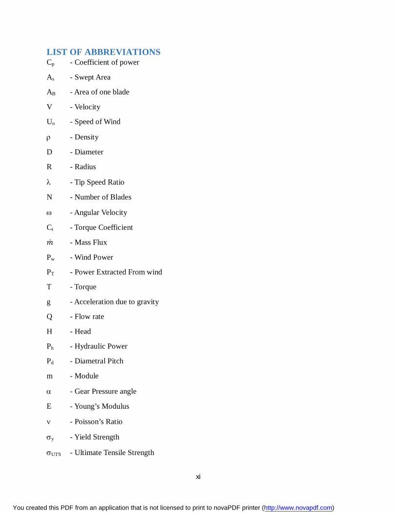
LIST OF ABBREVIATIONS Cp - Coefficient of power
As - Swept Area
AB - Area of one blade
V - Velocity
Uo - Speed of Wind
- Density
D - Diameter
R - Radius
- Tip Speed Ratio
N - Number of Blades
- Angular Velocity
Ct - Torque Coefficient
푚̇ - Mass Flux
Pw - Wind Power
PT - Power Extracted From wind
T - Torque
g - Acceleration due to gravity
Q - Flow rate
H - Head
Ph - Hydraulic Power
Pd - Diametral Pitch
m - Module
- Gear Pressure angle
E - Young’s Modulus
- Poisson’s Ratio
y - Yield Strength
UTS - Ultimate Tensile Strength
You created this PDF from an application that is not licensed to print to novaPDF printer (http://www.novapdf.com)

xii
- Shear Stress
J - Polar Moment of Inertia
F - Force
M - Moment
You created this PDF from an application that is not licensed to print to novaPDF printer (http://www.novapdf.com)
1
1.0 INTRODUCTION
1.1 DEFINITIONS Wind
This is air in motion and it is a natural resource that is freely available in space and moves at varying speeds depending on the geographical location.
Wind energy
Wind energy originates from solar energy where the sun heats the atmosphere unevenly causing
some parts to be warmer than others. The warmer patches of air rise and other air patches blow in
to replace them. Thus alternating air flow which results in wind.
Windmill
Windmills are machines that are used to harness the kinetic energy of the wind which blows over
the blades rotor assembly causing it to rotate on a shaft. The resulting shaft poweris then used to
provide mechanical work for pumping water.
1.2 BACKGROUND The increase is costs of fossil fuels has greatly lead to the development of alternative sources of
Green Energy that are environmental friendly and cheaper to produce. The major resource in this
category is wind energy.
The exact origin of the first use of wind power is not known, however one of the earliest known
uses dates back to 3500 B.C where they were used to drive sailboat using aerodynamic lift. The
advancements of this design were adapted to China where the first windmill was developed and
it was a vertical axis type that used sheet like wings to capture the wind. This setup was the
connected to pulleys or other transmission mechanisms to be used for pumping water or
grinding.
In the middle ages, wind energy was introduced in Northern Europe where Horizontal axis
windmills were used where the sails connected to a horizontal shaft attached to a tower with
You created this PDF from an application that is not licensed to print to novaPDF printer (http://www.novapdf.com)
2
gears and axles that were used to translate the horizontal motion into rotational motion. This type
of windmill used drag forces for similar purposes of grinding and sawing timber.
In the 19th Century, wind energy developed in the United States where horizontal axis windmills
were used for farms, ranches and to generate electricity. This is where the first multi-blade was
developed for irrigation purposes.
The wind power technology has evolved greatly and this has been motivated by the incredible
benefits resulting from wind energy. Very efficient and technologically up-to- date designs have
been developed and are used all over the country especially in arid and semi-arid areas to pump
water for domestic and irrigation purposes. Viability of windmills is however practical only in
areas with free flow of air and therefore site selection is very critical in the initial design process.
The power generated from the wind can be supplied directly to the national grid system or used
to drive other mechanical devices such as windmills and grinders. This has greatly reduced the
levels of pollution resulting from the use of fossil fuels. This project is mainly based on the
design of a windmill for water pumping.
1.3OBJECTIVE The main objective of the project was the design of a windmill. The following were the key
characteristics of the windmill to be designed:
Improved torque characteristics on the current designs.
Improved efficiency based on the current designs.
The design should be a low-cost model.
1.4PROBLEM STATEMENT Wind is a natural and renewable resource that is freely available all over the world.
Harnessing this power for pumping water would save a lot on power costs that are continuously
on the rise. Also, wind power is available in remote regions that have not yet been connected to
the national power grid. A windmill provides the best way of harnessing this wind power and
using it to pump water that is below the surface or delivering the water to a raised storage tank.
You created this PDF from an application that is not licensed to print to novaPDF printer (http://www.novapdf.com)

3
By using a rigorous design approach, an optimum windmill design was developed. It had
optimum power and optimum torque characteristics.
1.5SCOPE OF DESIGN The design of a windmill is a very wide subject and therefore our design is based on data
analysis of various components of windmill and their actual drawings. This includes the rotor
assembly i.e. the blade and the hub, transmission shafts (both vertical and horizontal) the gear
box which houses the gears, actuating pulley and the piston actuating mechanism, tail, turntable
and the 2meters additional rig that will be joined to the existing rig.
The design does not cover the design and selection of the pump but a desirable pump that can
function with the vertical movement of the actuating rod will be selected.
The design process started off with analysis of the existing Windmill designs and their respective
operating condition. This formed a rough idea of the eventual windmill design that would be
tailored to the Nairobi region and possibly the rest of Kenya. In order to achieve the optimum
design characteristics such as Torque and power produced by the windmill, various calculations
and structural analysis had to be done as well.
You created this PDF from an application that is not licensed to print to novaPDF printer (http://www.novapdf.com)
4
2.0 LITERATURE REVIEW
2.1 SITE SELECTION The viability of a windmill is greatly affected by its location. The site must have sufficient wind
power to move the windmill and also be away from obstructions that might cause turbulence.
The speed of wind for a given location is not constant and thus the climatic condition of the site
should be examined for over on a year and recorded on a wind map which is then used to analyze
the suitability of the site.
To avoid distractions, most windmills are located on hilly areas or the rigs are tall enough to
ensure the rotor is far above the obstacles. The site of our windmill had been identified and there
was no need for selection of another site. However we did an analysis on the site to determine its
suitability and the findings were as follows:
The winds speed of Nairobi varies from 3m/s to 4m/s and these were the maximum and
minimum wind speeds recorded from January to December in the year 2013, hence the
site is suitable.
The location of the windmill is strategically away from tall buildings and trees and
therefore minimal obstruction of the wind
2.2.1Advantages of Wind Power It is the cheapest source of energy. This is because it does not require importation and it is
readily available.
It is environmental friendly i.e. it is a major source of green energy as no greenhouse
emissions are released to the atmosphere during its production.
Require less labour expenses as maintenance is very minimal and few personnel are
required at the site.
2.2.2Disadvantages of Wind Power Varying wind speeds and directions make it difficult to use wind as a consistent source of
power.
You created this PDF from an application that is not licensed to print to novaPDF printer (http://www.novapdf.com)
5
Initial investment on construction and installation of wind power machinery is very
costly. In the year 2008-2009 the average investment required was $1300 and $1800 for
every kW the windmill was to produce (wind energy).
They produce so much noise and are therefore limited to areas away from homesteads
and also away from wildlife reserves.
2.3 TYPES OF WINDMILLS Windmills generally consist of two basic types with the classification being based on the
orientation of the axis of the rotor .The main classifications are discussed below:
2.3.1Vertical Axis Wind Turbine (VAWT) This has blades which are arranged on the vertical axis and are rotated by wind and therefore it
doesn’t require a yaw mechanism since it can harness wind from any direction. It does not rely
on the direction of the wind to generate power as in the case of the horizontal axis.
They usually operate closer to the ground which has an advantage of allowing for placement or
replacement of heavy equipment. However this is a disadvantage as winds are lower near ground
level hence less power output.
There are two main types of the VAWT namely:
2.3.1.1 Savonius It operates like a water wheel which uses drag forces. It has a simple design and is therefore
relatively simple and cheaper to build. It is mostly used in situations that do not require large
amounts of power. However, it is less powerful than most HAWT because it uses drag to rotate
itself and has a higher power to weight ratio. The total amount of turning torque of the
mechanism relies on the drag force on each blade.
2.3.1.2 Darrieus It uses blades similar to those used in the horizontal axis wind turbine (HAWT). It has two or
more curved blades that depend on wind in order to revolve around a central column. It functions
by generating a lift using the rotating motion of the blades. The wind acting on the blade creates
a rearward momentum change which propels the blade in the direction of rotation. This cannot
You created this PDF from an application that is not licensed to print to novaPDF printer (http://www.novapdf.com)
6
occur unless the blades are already rotating and therefore they require a separate means of
starting i.e. they are not self-starting.
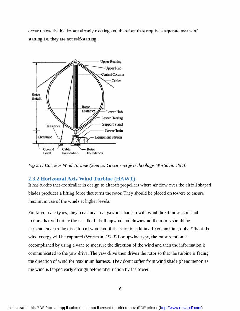
Fig 2.1: Darrieus Wind Turbine (Source: Green energy technology, Wortman, 1983)
2.3.2 Horizontal Axis Wind Turbine (HAWT) It has blades that are similar in design to aircraft propellers where air flow over the airfoil shaped
blades produces a lifting force that turns the rotor. They should be placed on towers to ensure
maximum use of the winds at higher levels.
For large scale types, they have an active yaw mechanism with wind direction sensors and
motors that will rotate the nacelle. In both upwind and downwind the rotors should be
perpendicular to the direction of wind and if the rotor is held in a fixed position, only 21% of the
wind energy will be captured (Wortman, 1983).For upwind type, the rotor rotation is
accomplished by using a vane to measure the direction of the wind and then the information is
communicated to the yaw drive. The yaw drive then drives the rotor so that the turbine is facing
the direction of wind for maximum harness. They don’t suffer from wind shade phenomenon as
the wind is tapped early enough before obstruction by the tower.
You created this PDF from an application that is not licensed to print to novaPDF printer (http://www.novapdf.com)
7
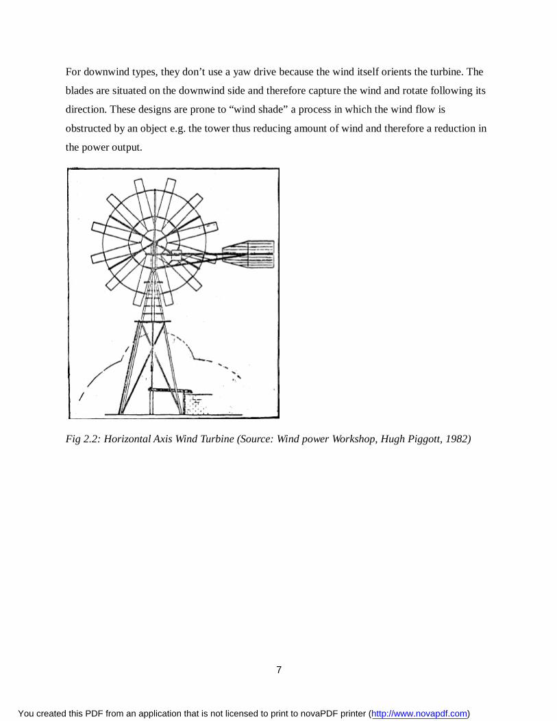
For downwind types, they don’t use a yaw drive because the wind itself orients the turbine. The
blades are situated on the downwind side and therefore capture the wind and rotate following its
direction. These designs are prone to “wind shade” a process in which the wind flow is
obstructed by an object e.g. the tower thus reducing amount of wind and therefore a reduction in
the power output.
Fig 2.2: Horizontal Axis Wind Turbine (Source: Wind power Workshop, Hugh Piggott, 1982)
You created this PDF from an application that is not licensed to print to novaPDF printer (http://www.novapdf.com)
8
3.0THEORY
3.1 DEFINITIONS
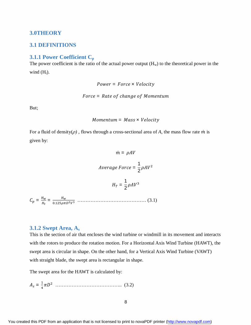
3.1.1 Power Coefficient Cp The power coefficient is the ratio of the actual power output (Hw) to the theoretical power in the
wind (Ht).
푃표푤푒푟 = 퐹표푟푐푒 × 푉푒푙표푐푖푡푦
퐹표푟푐푒 = 푅푎푡푒 표푓 푐ℎ푎푛푔푒 표푓 푀표푚푒푛푡푢푚
But;
푀표푚푒푛푡푢푚 = 푀푎푠푠 × 푉푒푙표푐푖푡푦
For a fluid of density() , flows through a cross-sectional area of A, the mass flow rate 푚̇ is
given by:
푚̇ = 휌퐴푉
퐴푣푒푟푎푔푒 퐹표푟푐푒 =12휌퐴푉
퐻 =12휌퐴푉
퐶 = =.
…………………………………… (3.1)
3.1.2 Swept Area, As This is the section of air that encloses the wind turbine or windmill in its movement and interacts
with the rotors to produce the rotation motion. For a Horizontal Axis Wind Turbine (HAWT), the
swept area is circular in shape. On the other hand, for a Vertical Axis Wind Turbine (VAWT)
with straight blade, the swept area is rectangular in shape.
The swept area for the HAWT is calculated by:
퐴 = 휋퐷 ………………………………….. (3.2)
You created this PDF from an application that is not licensed to print to novaPDF printer (http://www.novapdf.com)
9
Where: As – Swept area (m2)
D – Rotor Diameter (m)
NOTE: The rotor radius is the distance from the tip of one blade to the center. The diameter is
twice this length.
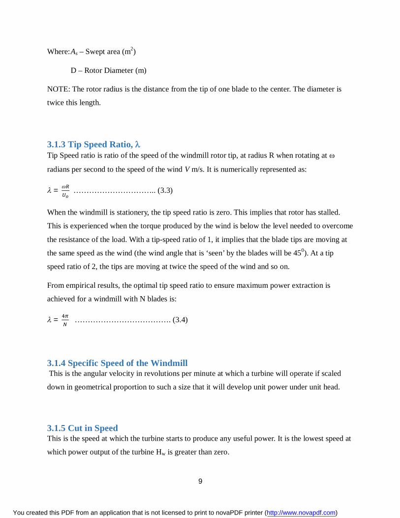
3.1.3 Tip Speed Ratio, Tip Speed ratio is ratio of the speed of the windmill rotor tip, at radius R when rotating at
radians per second to the speed of the wind V m/s. It is numerically represented as:
= ………………………….. (3.3)
When the windmill is stationery, the tip speed ratio is zero. This implies that rotor has stalled.
This is experienced when the torque produced by the wind is below the level needed to overcome
the resistance of the load. With a tip-speed ratio of 1, it implies that the blade tips are moving at
the same speed as the wind (the wind angle that is ‘seen’ by the blades will be 450). At a tip
speed ratio of 2, the tips are moving at twice the speed of the wind and so on.
From empirical results, the optimal tip speed ratio to ensure maximum power extraction is
achieved for a windmill with N blades is:
= ………………………………. (3.4)
3.1.4 Specific Speed of the Windmill This is the angular velocity in revolutions per minute at which a turbine will operate if scaled
down in geometrical proportion to such a size that it will develop unit power under unit head.
3.1.5 Cut in Speed This is the speed at which the turbine starts to produce any useful power. It is the lowest speed at
which power output of the turbine Hw is greater than zero.
You created this PDF from an application that is not licensed to print to novaPDF printer (http://www.novapdf.com)
10
3.1.6 Cut out Speed This is the wind speed at which the turbine stops to produce any useful power. This is the highest
speed at which power developed by the wind turbine is just zero.
3.1.7 Rated Wind Speed Wind speed at which the rated power is produced, this value defines the shape of the power
curve.
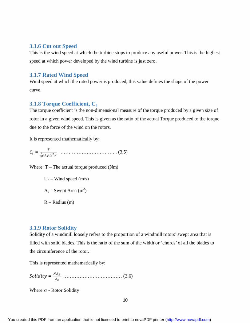
3.1.8 Torque Coefficient, Ct The torque coefficient is the non-dimensional measure of the torque produced by a given size of
rotor in a given wind speed. This is given as the ratio of the actual Torque produced to the torque
due to the force of the wind on the rotors.
It is represented mathematically by:
퐶 = …………………………….. (3.5)
Where: T – The actual torque produced (Nm)
Uo – Wind speed (m/s)
As – Swept Area (m2)
R – Radius (m)
3.1.9 Rotor Solidity Solidity of a windmill loosely refers to the proportion of a windmill rotors’ swept area that is
filled with solid blades. This is the ratio of the sum of the width or ‘chords’ of all the blades to
the circumference of the rotor.
This is represented mathematically by:
푆표푙푖푑푖푡푦 = ……………………………… (3.6)
Where: - Rotor Solidity
You created this PDF from an application that is not licensed to print to novaPDF printer (http://www.novapdf.com)

11
N – Number of Blades
AB – Area of one blade (m2)
As – Swept Area (m2)
Most of the HAWT Windmills that are used on wind pumps are Multi-bladed rotors. They are
usually said to be of high solidity due to the fact that a large proportion of the swept area is
‘solid’ with blades. High solidity means that the windmill will run at a very low speed and
creating high torque in the process. The blades of such high solidity windmills set a rather coarse
angle to the plane of rotation just like a screw with a coarse thread. At maximum efficiency, the
tip-speed ratio is very low at approximately 1.25. The efficiency of the high solidity windmills is
slightly lower than that of the faster types of rotors. These multi-bladed rotors have a much
higher torque coefficient at zero tip-speed ratio (i.e. between 0.5 and 0.6) than any other types.
The starting torque, which is usually higher than the running torque, together with the low speed
of rotation in the given wind regime make the multi-bladed high solidity windmill suitable for
driving the reciprocating borehole pumps.
On the other hand, the low solidity rotors have a higher efficiency with the highest values of Cp.
They have very high tip speed ratio. To achieve these optimum operating conditions, the rotors
have to be set at a slight angle to the plane of rotation. The starting torque is very low implying
that they can only start against the loads that require little torque to start them such as centrifugal
pumps and electricity generators.
A typical windmill will have a starting torque that is five to twenty times the starting torque of
the three bladed low solidity wind turbines.
3.1.10 Thrust Coefficient CT This is non-dimensional measure of the force that falls on the windmill. It given as the ratio of
the actual thrust force on the windmill to the average force from the wind.
It is represented mathematically as:
퐹표푟푐푒 표푓 푡ℎ푒 푊푖푛푑 =12휌퐴 푈
You created this PDF from an application that is not licensed to print to novaPDF printer (http://www.novapdf.com)
12
Thrust Force on the windmill, FT;
퐹 =12퐶 휌퐴 푈
∴ 퐶 = ………………………………….. (3.7)
3.2 WIND POWER DERIVATION
3.2.1 Wind Power: 푊푖푛푑 푃표푤푒푟 (P ) = 퐾푖푛푒푡푖푐 퐸푛푒푟푔푦 푝푒푟 푈푛푖푡 푇푖푚푒
= 푚̇푣 ……………………………………. (3.8)
Where:(푀푎푠푠 퐹푙푢푥) 푚̇ = = 휌퐴푣
휌 = 퐷푒푛푠푖푡푦 표푓 푎푖푟 (퐾푔 푚⁄ )
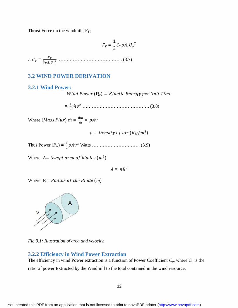
Thus Power (Pw) = 휌퐴푣 Watts …………………………. (3.9)
Where: A= 푆푤푒푝푡 푎푟푒푎 표푓 푏푙푎푑푒푠 (푚 )
퐴 = 휋푅
Where: R = 푅푎푑푖푢푠 표푓 푡ℎ푒 퐵푙푎푑푒 (푚)
Fig 3.1: Illustration of area and velocity.
3.2.2 Efficiency in Wind Power Extraction The efficiency in wind Power extraction is a function of Power Coefficient Cp, where Cp is the
ratio of power Extracted by the Windmill to the total contained in the wind resource.
You created this PDF from an application that is not licensed to print to novaPDF printer (http://www.novapdf.com)
13
Cp= ……………………………………. (3.10)
Where: Windmill Power Extracted PT = 푃 × 퐶
= 휌퐴푣 × 퐶 (Watts)
The Betz Limit is the maximum possible value for Cpwhich is equal to but the optimum
possible for a multi-blade windmill is 30%.
3.2.3 Torque Extracted In the windmill used for pumping water, Torque output is key.
Torque is given by the ratio power extracted to rotor speed.
T = ……………………………………………….. (3.11)
Rotor Speed 휔 =
Where: 푣 = 푊푖푛푑 푆푝푒푒푑 (푚/푠)
휆= 푇푖푝 푠푝푒푒푑 푟푎푡푖표
R = 퐿푒푛푔푡ℎ 표푓 푏푙푎푑푒 (푚)
Thus: T= …………………………………. (3.12)
But PT= 휌휋푅 푣 × 퐶 Watts
Therefore: T= ×
T = 푣 퐶 (Nm) ………………………….. (3.13)
You created this PDF from an application that is not licensed to print to novaPDF printer (http://www.novapdf.com)
14
3.3 EFFICIENCY, POWER AND TORQUE CHARACTERISTICS
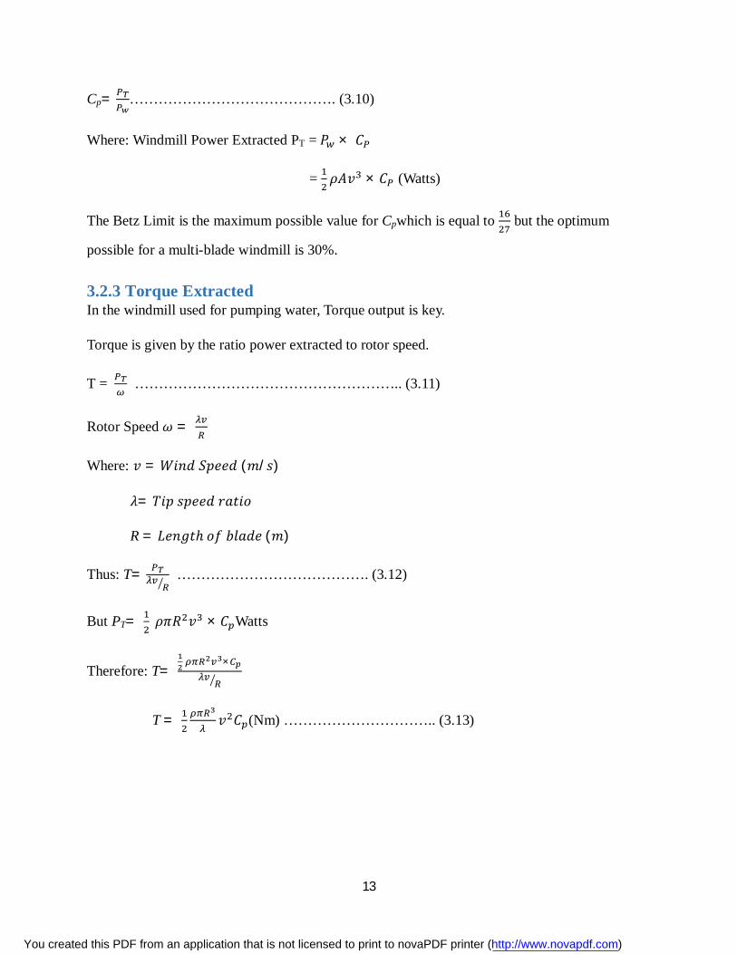
3.3.1 Power – Speed Characteristics In order for the wind pump to work as desired, the pumping requirements must be matched with
the wind speed as well as the rotor shaft power available. The sample figure below indicates how
one would match a wind speed of 5 m/s with required pump power requirement.
Fig 3.2: Power of a windmill as a function of rotational speed for various wind speeds. Source
S.B Kedare (2003)
You created this PDF from an application that is not licensed to print to novaPDF printer (http://www.novapdf.com)
15
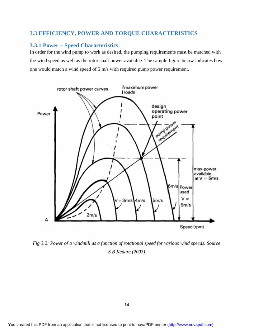
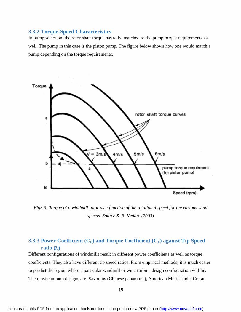
3.3.2 Torque-Speed Characteristics In pump selection, the rotor shaft torque has to be matched to the pump torque requirements as
well. The pump in this case is the piston pump. The figure below shows how one would match a
pump depending on the torque requirements.
Fig3.3: Torque of a windmill rotor as a function of the rotational speed for the various wind
speeds. Source S. B. Kedare (2003)
3.3.3 Power Coefficient (CP) and Torque Coefficient (CT) against Tip Speed ratio ()
Different configurations of windmills result in different power coefficients as well as torque
coefficients. They also have different tip speed ratios. From empirical methods, it is much easier
to predict the region where a particular windmill or wind turbine design configuration will lie.
The most common designs are; Savonius (Chinese panamone), American Multi-blade, Cretan
You created this PDF from an application that is not licensed to print to novaPDF printer (http://www.novapdf.com)
16
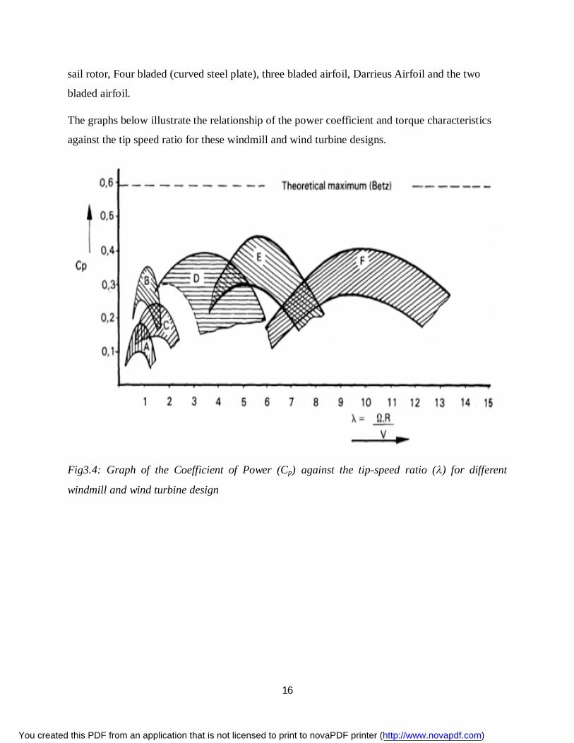
sail rotor, Four bladed (curved steel plate), three bladed airfoil, Darrieus Airfoil and the two
bladed airfoil.
The graphs below illustrate the relationship of the power coefficient and torque characteristics
against the tip speed ratio for these windmill and wind turbine designs.
Fig3.4: Graph of the Coefficient of Power (Cp) against the tip-speed ratio () for different
windmill and wind turbine design
You created this PDF from an application that is not licensed to print to novaPDF printer (http://www.novapdf.com)
17
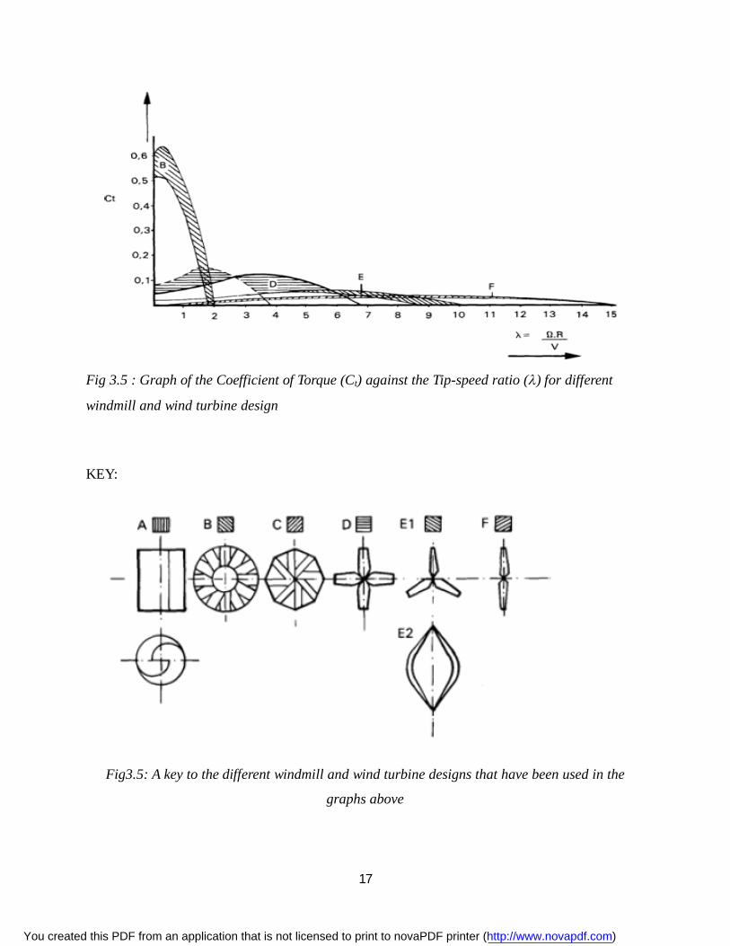
Fig 3.5 : Graph of the Coefficient of Torque (Ct) against the Tip-speed ratio () for different
windmill and wind turbine design
KEY:
Fig3.5: A key to the different windmill and wind turbine designs that have been used in the
graphs above
You created this PDF from an application that is not licensed to print to novaPDF printer (http://www.novapdf.com)
18
4. DESIGN
4.1 BLADE
4.1.1 Blade Design Consideration Betz’ Theorem Revisited
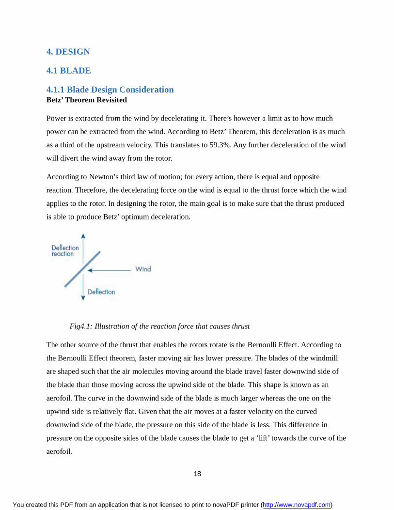
Power is extracted from the wind by decelerating it. There’s however a limit as to how much
power can be extracted from the wind. According to Betz’ Theorem, this deceleration is as much
as a third of the upstream velocity. This translates to 59.3%. Any further deceleration of the wind
will divert the wind away from the rotor.
According to Newton’s third law of motion; for every action, there is equal and opposite
reaction. Therefore, the decelerating force on the wind is equal to the thrust force which the wind
applies to the rotor. In designing the rotor, the main goal is to make sure that the thrust produced
is able to produce Betz’ optimum deceleration.
Fig4.1: Illustration of the reaction force that causes thrust
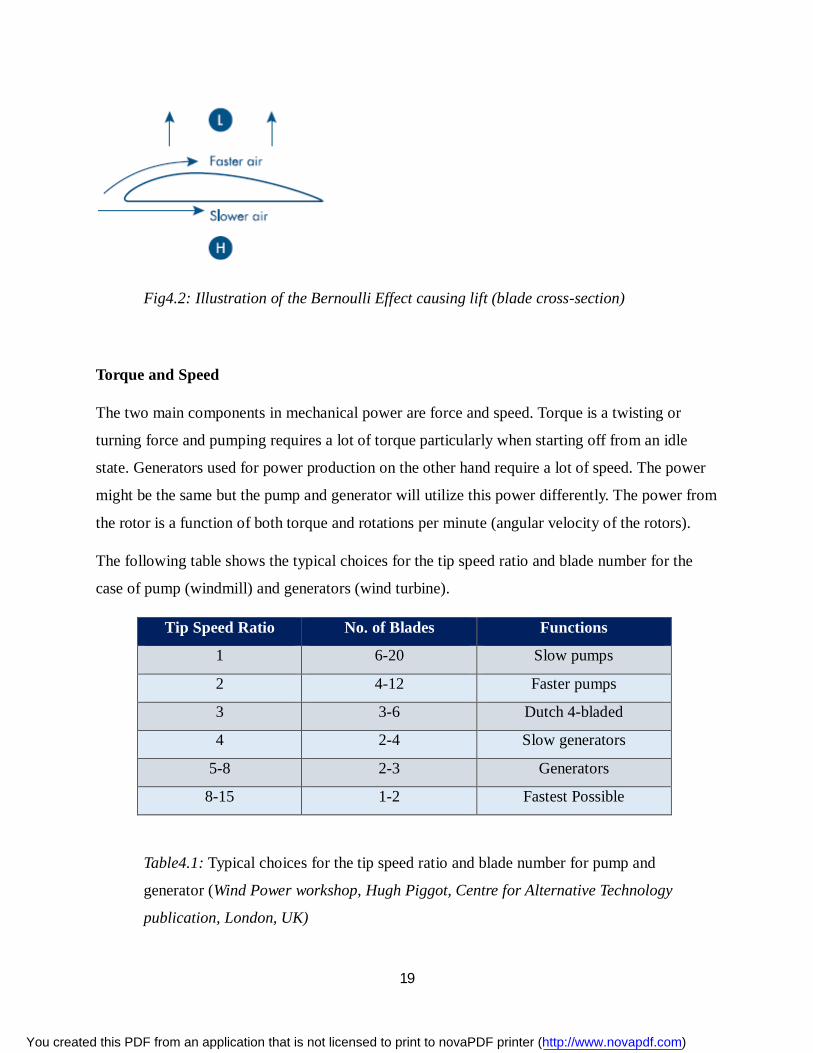
The other source of the thrust that enables the rotors rotate is the Bernoulli Effect. According to
the Bernoulli Effect theorem, faster moving air has lower pressure. The blades of the windmill
are shaped such that the air molecules moving around the blade travel faster downwind side of
the blade than those moving across the upwind side of the blade. This shape is known as an
aerofoil. The curve in the downwind side of the blade is much larger whereas the one on the
upwind side is relatively flat. Given that the air moves at a faster velocity on the curved
downwind side of the blade, the pressure on this side of the blade is less. This difference in
pressure on the opposite sides of the blade causes the blade to get a ‘lift’ towards the curve of the
aerofoil.
You created this PDF from an application that is not licensed to print to novaPDF printer (http://www.novapdf.com)
19
Fig4.2: Illustration of the Bernoulli Effect causing lift (blade cross-section)
Torque and Speed
The two main components in mechanical power are force and speed. Torque is a twisting or
turning force and pumping requires a lot of torque particularly when starting off from an idle
state. Generators used for power production on the other hand require a lot of speed. The power
might be the same but the pump and generator will utilize this power differently. The power from
the rotor is a function of both torque and rotations per minute (angular velocity of the rotors).
The following table shows the typical choices for the tip speed ratio and blade number for the
case of pump (windmill) and generators (wind turbine).
Tip Speed Ratio No. of Blades Functions
1 6-20 Slow pumps
2 4-12 Faster pumps
3 3-6 Dutch 4-bladed
4 2-4 Slow generators
5-8 2-3 Generators
8-15 1-2 Fastest Possible
Table4.1: Typical choices for the tip speed ratio and blade number for pump and
generator (Wind Power workshop, Hugh Piggot, Centre for Alternative Technology
publication, London, UK)
You created this PDF from an application that is not licensed to print to novaPDF printer (http://www.novapdf.com)
20
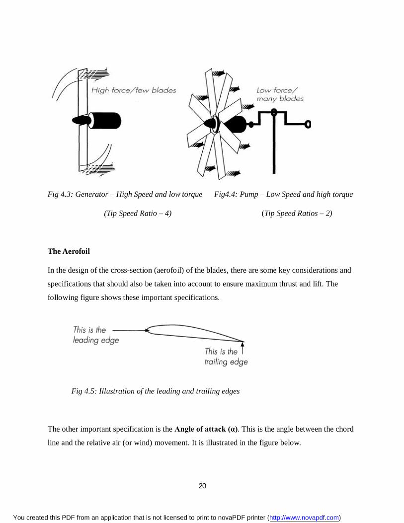
Fig 4.3: Generator – High Speed and low torque Fig4.4: Pump – Low Speed and high torque
(Tip Speed Ratio – 4) (Tip Speed Ratios – 2)
The Aerofoil
In the design of the cross-section (aerofoil) of the blades, there are some key considerations and
specifications that should also be taken into account to ensure maximum thrust and lift. The
following figure shows these important specifications.
Fig 4.5: Illustration of the leading and trailing edges
The other important specification is the Angle of attack (α). This is the angle between the chord
line and the relative air (or wind) movement. It is illustrated in the figure below.
You created this PDF from an application that is not licensed to print to novaPDF printer (http://www.novapdf.com)
21
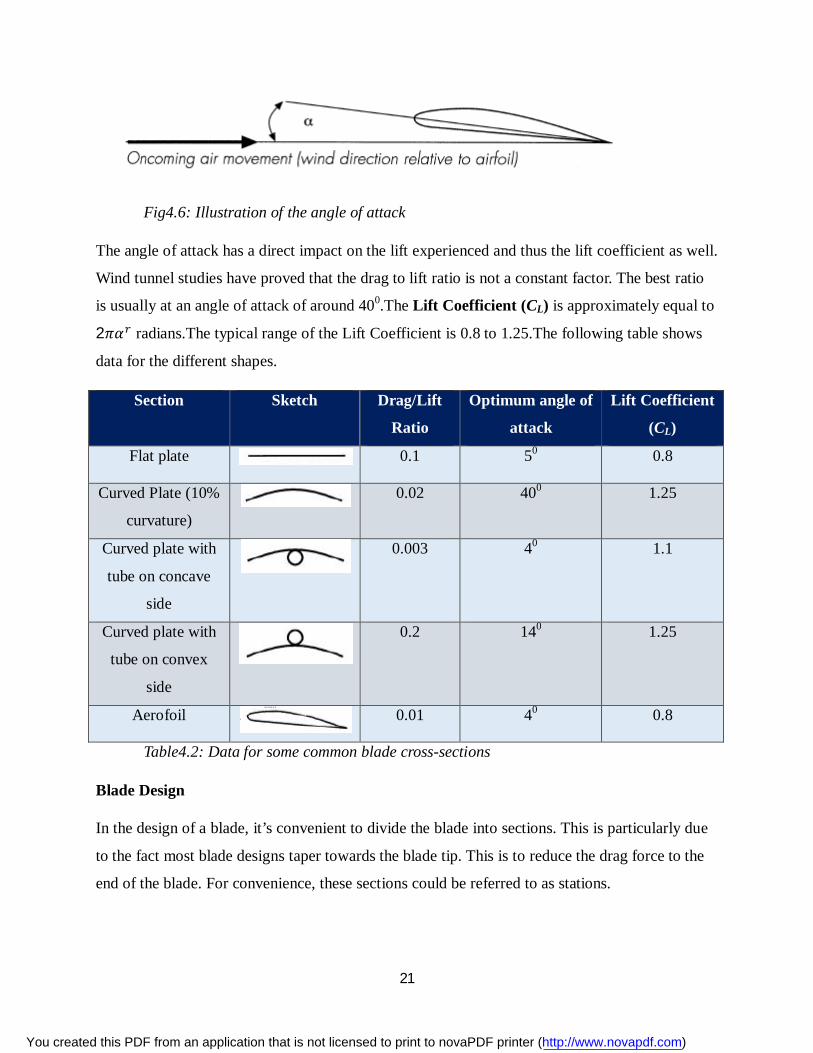
Fig4.6: Illustration of the angle of attack
The angle of attack has a direct impact on the lift experienced and thus the lift coefficient as well.
Wind tunnel studies have proved that the drag to lift ratio is not a constant factor. The best ratio
is usually at an angle of attack of around 400.The Lift Coefficient (CL) is approximately equal to
2휋훼 radians.The typical range of the Lift Coefficient is 0.8 to 1.25.The following table shows
data for the different shapes.
Section Sketch Drag/Lift
Ratio
Optimum angle of
attack
Lift Coefficient
(CL)
Flat plate 0.1 50 0.8
Curved Plate (10%
curvature) 0.02 400 1.25
Curved plate with
tube on concave
side
0.003 40 1.1
Curved plate with
tube on convex
side
0.2 140 1.25
Aerofoil
0.01 40 0.8
Table4.2: Data for some common blade cross-sections
Blade Design
In the design of a blade, it’s convenient to divide the blade into sections. This is particularly due
to the fact most blade designs taper towards the blade tip. This is to reduce the drag force to the
end of the blade. For convenience, these sections could be referred to as stations.
You created this PDF from an application that is not licensed to print to novaPDF printer (http://www.novapdf.com)
22
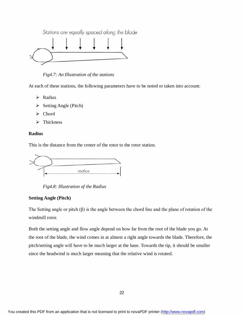
Fig4.7: An Illustration of the stations
At each of these stations, the following parameters have to be noted or taken into account:
Radius
Setting Angle (Pitch)
Chord
Thickness
Radius
This is the distance from the center of the rotor to the rotor station.
Fig4.8: Illustration of the Radius
Setting Angle (Pitch)
The Setting angle or pitch (β) is the angle between the chord line and the plane of rotation of the
windmill rotor.
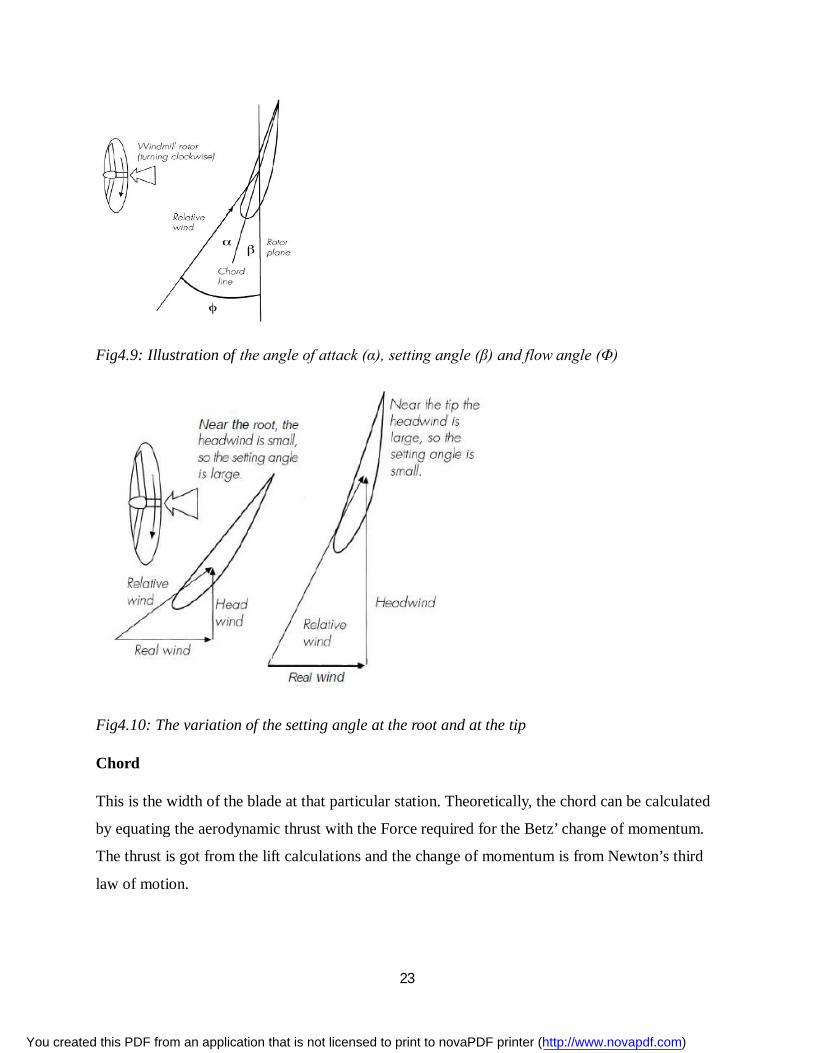
Both the setting angle and flow angle depend on how far from the root of the blade you go. At
the root of the blade, the wind comes in at almost a right angle towards the blade. Therefore, the
pitch/setting angle will have to be much larger at the base. Towards the tip, it should be smaller
since the headwind is much larger meaning that the relative wind is rotated.
You created this PDF from an application that is not licensed to print to novaPDF printer (http://www.novapdf.com)
23
Fig4.9: Illustration of the angle of attack (α), setting angle (β) and flow angle (Φ)
Fig4.10: The variation of the setting angle at the root and at the tip
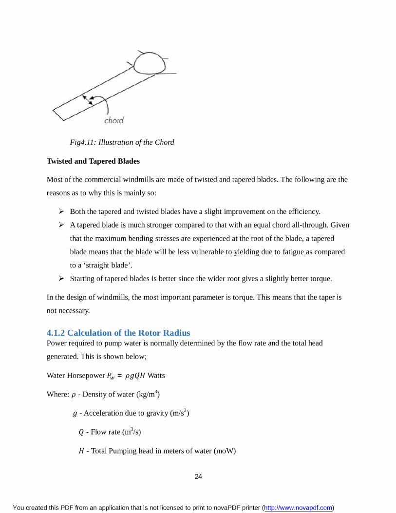
Chord
This is the width of the blade at that particular station. Theoretically, the chord can be calculated
by equating the aerodynamic thrust with the Force required for the Betz’ change of momentum.
The thrust is got from the lift calculations and the change of momentum is from Newton’s third
law of motion.
You created this PDF from an application that is not licensed to print to novaPDF printer (http://www.novapdf.com)
24
Fig4.11: Illustration of the Chord
Twisted and Tapered Blades
Most of the commercial windmills are made of twisted and tapered blades. The following are the
reasons as to why this is mainly so:
Both the tapered and twisted blades have a slight improvement on the efficiency.
A tapered blade is much stronger compared to that with an equal chord all-through. Given
that the maximum bending stresses are experienced at the root of the blade, a tapered
blade means that the blade will be less vulnerable to yielding due to fatigue as compared
to a ‘straight blade’.
Starting of tapered blades is better since the wider root gives a slightly better torque.
In the design of windmills, the most important parameter is torque. This means that the taper is
not necessary.
4.1.2 Calculation of the Rotor Radius Power required to pump water is normally determined by the flow rate and the total head
generated. This is shown below;
Water Horsepower 푃 = 휌푔푄퐻 Watts
Where: 휌 - Density of water (kg/m3)
푔 - Acceleration due to gravity (m/s2)
푄 - Flow rate (m3/s)
퐻 - Total Pumping head in meters of water (moW)
You created this PDF from an application that is not licensed to print to novaPDF printer (http://www.novapdf.com)
25
Proposed design requirements
Proposed head = 30 m
Proposed Volume Flow rate= 15m3 per day =0.1736 × 10 m3 per second
Taking the daily mean wind speed in Nairobi;
Highest daily mean = 4 m/s
Lowest daily mean = 3 m/s
Given the average wind speeds, the lowest average mean wind speed was selected i.e. 3.5 m/s.
The average atmospheric temperatures for Nairobi are at an average low of 120C and a high of
280C.
Power required to pump the water is given by:
Hydraulic Power, Ph= 휌푔푄퐻W
Substituting for g=9.81 m2/s; Q = 0.1736 × 10 m3/s; H = 30 m
= 1000 × 9.81 × 0.1736 × 10 × 30
= 51.09048 푊
In order to the power required from the wind, various losses have to be considered.
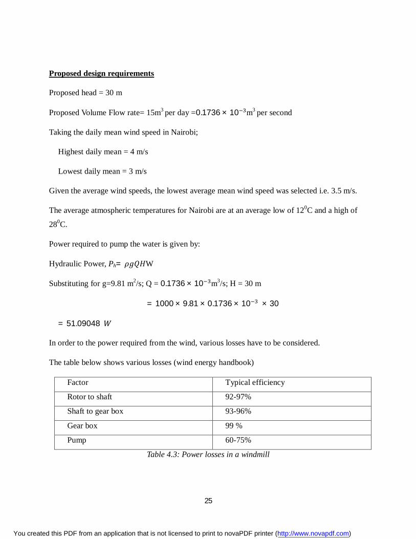
The table below shows various losses (wind energy handbook)
Factor Typical efficiency
Rotor to shaft 92-97%
Shaft to gear box 93-96%
Gear box 99 %
Pump 60-75%
Table 4.3: Power losses in a windmill
You created this PDF from an application that is not licensed to print to novaPDF printer (http://www.novapdf.com)
26
푒푓푓푖푐푖푒푛푐푦 =표푢푡푝푢푡푖푛푝푢푡 × 100%
Hence before losses occur, the input power to the system is given by:
푖푛푝푢푡 =표푢푡푝푢푡
푒푓푓푖푐푖푒푛푐푦 × 100
1. Before pump loss
Average Efficiency of pump is 67.7%
푃 =51.09048
67.5 × 100
= 75.6897 W
This is the power that is transmitted from the shaft to the pump.
2. Before shaft losses
Average efficiency of the shaft from the gearbox to the pump is 94.5 %.
푃 =75.6897
94.5 × 100
= 80.0948 푊
This is the power that is transmitted from the gearbox to the vertical shaft
3. Before gearbox losses
Average efficiency of the gear box is given as 99% which is the actual efficiency of the gears
푃 =80.0948
99 × 100
= 80.9039 푊
This is the total power transmitted from the horizontal shaft to the gearbox.
4. Before shaft losses
The efficiency of the horizontal shaft is given by 94.5%
푃 =80.9039
94.5 × 100
= 85.6125 푊
This is the amount of power required from the wind.
You created this PDF from an application that is not licensed to print to novaPDF printer (http://www.novapdf.com)
27
5. However, according to the Betz limit, the efficiency in wind power extraction is a function
Power Coefficient Cp, where Cp is the ratio of power Extracted by the Windmill to the total
contained in the wind resource.
Cp=
Where: Windmill Power Extracted PT = 푃 × 퐶
= 휌퐴푣 × 퐶 (Watts)
The Betz Limit is the maximum possible value for Cpwhich is equal to and therefore
making the maximum efficiency being 59%.
However the maximum practical value of Cpis 0.3 (wind power handbook)
Hence the power intercepted by the wind is given by:
푃 =85.6125
0.3 × 100
= 285.3751 푊
This is the power in the wind.
6. The power can also be calculated by the formula;
푃 = 휌퐴푣 kW
Where: A- Area covered by the blades
Atmospheric air conditions;
Mean wind speed = 3.5 m/s
Mean temperature = = 20℃
Pressure = 1.02 Bars
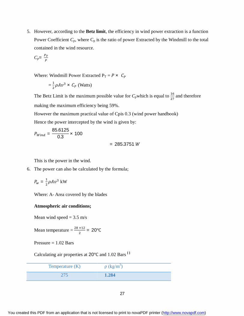
Calculating air properties at 20℃ and 1.02 Bars [ ]
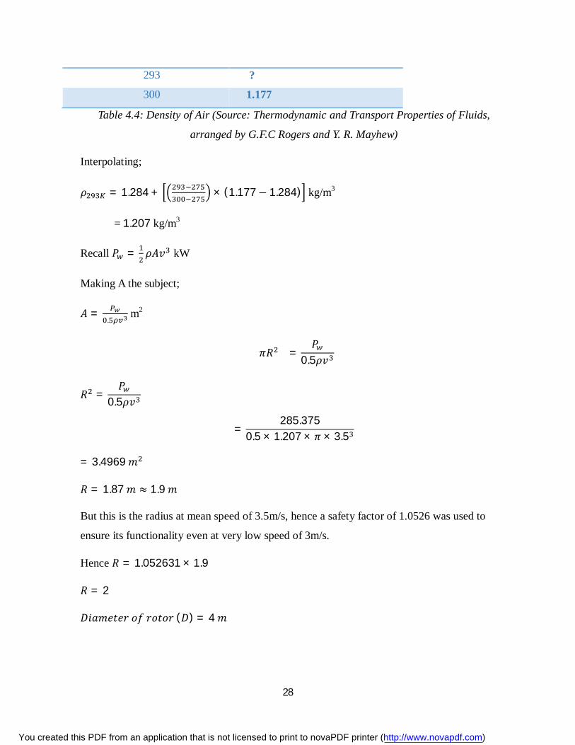
Temperature (K) ρ (kg/m3)
275 1.284
You created this PDF from an application that is not licensed to print to novaPDF printer (http://www.novapdf.com)
28
293 ?
300 1.177
Table 4.4: Density of Air (Source: Thermodynamic and Transport Properties of Fluids,
arranged by G.F.C Rogers and Y. R. Mayhew)
Interpolating;
휌 = 1.284 + × (1.177− 1.284) kg/m3
= 1.207 kg/m3
Recall 푃 = 휌퐴푣 kW
Making A the subject;
퐴 =.
m2
휋푅 =푃
0.5휌푣
푅 =푃
0.5휌푣
=285.375
0.5 × 1.207 × 휋 × 3.5
= 3.4969 푚
푅 = 1.87 푚 ≈ 1.9 푚
But this is the radius at mean speed of 3.5m/s, hence a safety factor of 1.0526 was used to
ensure its functionality even at very low speed of 3m/s.
Hence 푅 = 1.052631 × 1.9
푅 = 2
퐷푖푎푚푒푡푒푟 표푓 푟표푡표푟 (퐷) = 4 푚
You created this PDF from an application that is not licensed to print to novaPDF printer (http://www.novapdf.com)
29
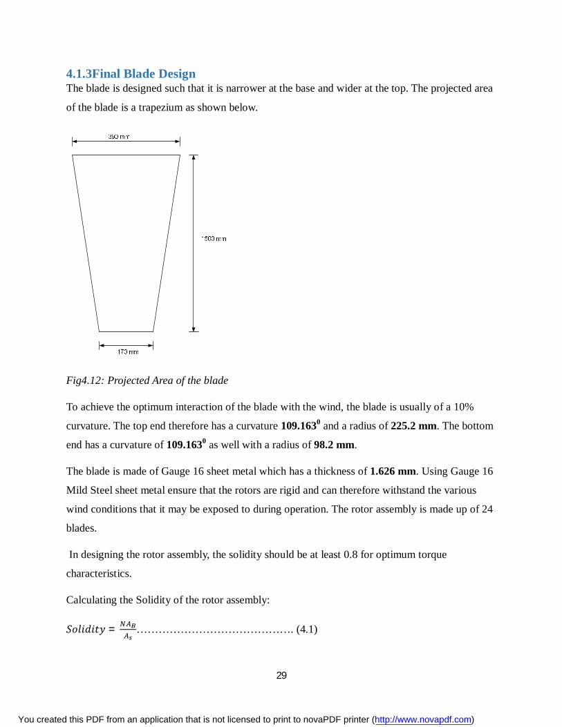
4.1.3Final Blade Design The blade is designed such that it is narrower at the base and wider at the top. The projected area
of the blade is a trapezium as shown below.
Fig4.12: Projected Area of the blade
To achieve the optimum interaction of the blade with the wind, the blade is usually of a 10%
curvature. The top end therefore has a curvature 109.1630 and a radius of 225.2 mm. The bottom
end has a curvature of 109.1630 as well with a radius of 98.2 mm.
The blade is made of Gauge 16 sheet metal which has a thickness of 1.626 mm. Using Gauge 16
Mild Steel sheet metal ensure that the rotors are rigid and can therefore withstand the various
wind conditions that it may be exposed to during operation. The rotor assembly is made up of 24
blades.
In designing the rotor assembly, the solidity should be at least 0.8 for optimum torque
characteristics.
Calculating the Solidity of the rotor assembly:
푆표푙푖푑푖푡푦 = ……………………………………. (4.1)
You created this PDF from an application that is not licensed to print to novaPDF printer (http://www.novapdf.com)
30
Where:
N – Number of Blades
AB – Area of one blade (m2)
As – Swept Area (m2)
퐴 =12 × 1.5(0.39 + 0.17) = 0.42 푚
퐴 = 휋푅 = 휋 × 2 = 12.5664 푚
∴ 푆표푙푖푑푖푡푦 =24 × 0.4212.5664 = ퟎ.ퟖퟎퟐퟏ
The solidity for the rotor design is 0.8021 which meets the threshold to achieve the best torque
characteristics.
At the base of the blade, it is bolted to a support that is also bolted onto the inner ring. This base
support ensures a rigid framework. The blade is joined to the outer ring by a weld joint. A
support similar to that at the base could be added for extra support. This might be vital for
windmills that might be exposed to high wind speeds for prolonged periods of time.
4.2 POWER TRANSMISSION MECHANISMS USED Gears, shafts and bearings are the fundamental transmission mechanisms used in most
engineering processes. They are the primary components used in gearboxes, drive trains and
transmissions.
4.2.1 Gears These are wheel-like shaped components that have equally spaced teeth around their outer
periphery and it engages another toothed mechanism in order to change the speed or direction of
transmitted motion .Gears are mounted on rotatable shafts with the teeth on one gear meshing
with the teeth of the other gear and thus transmitting rotary motion in the process. This also
causes transfer of torque from one part of the machine to the other.
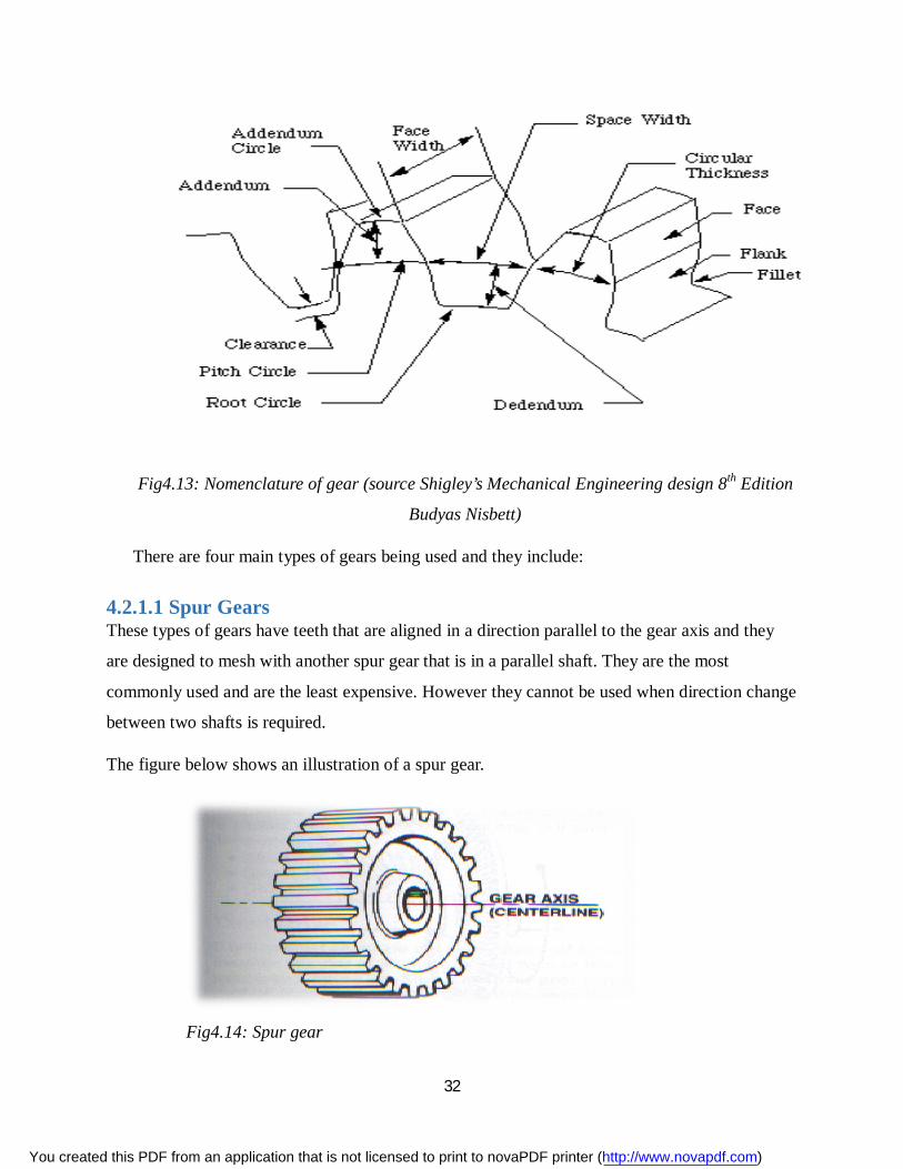
Gear terminologies:
You created this PDF from an application that is not licensed to print to novaPDF printer (http://www.novapdf.com)
31
Pinion- this is the smaller gear of the two gears.
The larger gear is usually called gear regardless of which is doing the driving.
Clearance-this is equal to the whole depth minus the working depth.
Dedendum-this is the radial depth of a tooth below the pitch circle.
Addendum-this is the radial height of the tooth above the pitch circle.
Circular pitch- this is the distance along the pitch circle from a point on one gear tooth
to a similar point on an adjacent gear tooth.
Diametral pitch (Pd): The number of teeth of a gear unit pitch diameter. A toothed gear
must have an integral number of teeth. The circular pitch, therefore, equals the pitch
circumference divided by the number of teeth. The diametral pitch is, by definition, the
number of teeth divided by the pitch diameter. That is:
………………………………… (4.2)
Module (m): Pitch diameter divided by number of teeth. The pitch diameter is usually
specified in inches or millimeters; in the former case the module is the inverse of
diametral pitch.
m = D/N
Pressure angle ( ): The angle between the common normal at the point of tooth contact
and the common tangent to the pitch circles. It is also the angle between the line of action
and the common tangent.
.
You created this PDF from an application that is not licensed to print to novaPDF printer (http://www.novapdf.com)
32
Fig4.13: Nomenclature of gear (source Shigley’s Mechanical Engineering design 8th Edition
Budyas Nisbett)
There are four main types of gears being used and they include:
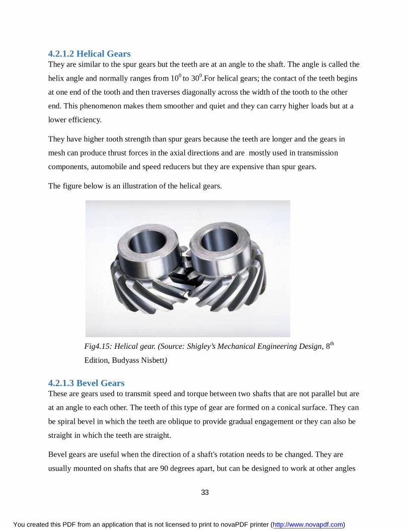
4.2.1.1 Spur Gears These types of gears have teeth that are aligned in a direction parallel to the gear axis and they
are designed to mesh with another spur gear that is in a parallel shaft. They are the most
commonly used and are the least expensive. However they cannot be used when direction change
between two shafts is required.
The figure below shows an illustration of a spur gear.
Fig4.14: Spur gear
You created this PDF from an application that is not licensed to print to novaPDF printer (http://www.novapdf.com)
33
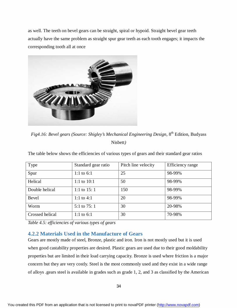
4.2.1.2 Helical Gears They are similar to the spur gears but the teeth are at an angle to the shaft. The angle is called the
helix angle and normally ranges from 100 to 300.For helical gears; the contact of the teeth begins
at one end of the tooth and then traverses diagonally across the width of the tooth to the other
end. This phenomenon makes them smoother and quiet and they can carry higher loads but at a
lower efficiency.
They have higher tooth strength than spur gears because the teeth are longer and the gears in
mesh can produce thrust forces in the axial directions and are mostly used in transmission
components, automobile and speed reducers but they are expensive than spur gears.
The figure below is an illustration of the helical gears.
Fig4.15: Helical gear. (Source: Shigley’s Mechanical Engineering Design, 8th
Edition, Budyass Nisbett)
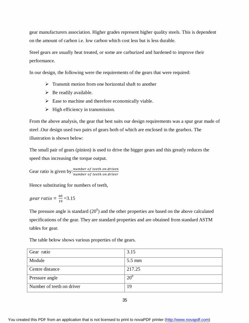
4.2.1.3 Bevel Gears These are gears used to transmit speed and torque between two shafts that are not parallel but are
at an angle to each other. The teeth of this type of gear are formed on a conical surface. They can
be spiral bevel in which the teeth are oblique to provide gradual engagement or they can also be
straight in which the teeth are straight.
Bevel gears are useful when the direction of a shaft's rotation needs to be changed. They are
usually mounted on shafts that are 90 degrees apart, but can be designed to work at other angles
You created this PDF from an application that is not licensed to print to novaPDF printer (http://www.novapdf.com)
34
as well. The teeth on bevel gears can be straight, spiral or hypoid. Straight bevel gear teeth
actually have the same problem as straight spur gear teeth as each tooth engages; it impacts the
corresponding tooth all at once
Fig4.16: Bevel gears (Source: Shigley’s Mechanical Engineering Design, 8th Edition, Budyass
Nisbett)
The table below shows the efficiencies of various types of gears and their standard gear ratios
Type Standard gear ratio Pitch line velocity Efficiency range
Spur 1:1 to 6:1 25 98-99%
Helical 1:1 to 10:1 50 98-99%
Double helical 1:1 to 15: 1 150 98-99%
Bevel 1:1 to 4:1 20 98-99%
Worm 5:1 to 75: 1 30 20-98%
Crossed helical 1:1 to 6:1 30 70-98%
Table 4.5: efficiencies of various types of gears
4.2.2 Materials Used in the Manufacture of Gears Gears are mostly made of steel, Bronze, plastic and iron. Iron is not mostly used but it is used
when good castability properties are desired. Plastic gears are used due to their good moldability
properties but are limited in their load carrying capacity. Bronze is used where friction is a major
concern but they are very costly. Steel is the most commonly used and they exist in a wide range
of alloys .gears steel is available in grades such as grade 1, 2, and 3 as classified by the American
You created this PDF from an application that is not licensed to print to novaPDF printer (http://www.novapdf.com)
35
gear manufacturers association. Higher grades represent higher quality steels. This is dependent
on the amount of carbon i.e. low carbon which cost less but is less durable.
Steel gears are usually heat treated, or some are carburized and hardened to improve their
performance.
In our design, the following were the requirements of the gears that were required:
Transmit motion from one horizontal shaft to another
Be readily available.
Ease to machine and therefore economically viable.
High efficiency in transmission.
From the above analysis, the gear that best suits our design requirements was a spur gear made of
steel .Our design used two pairs of gears both of which are enclosed in the gearbox. The
illustration is shown below:
The small pair of gears (pinion) is used to drive the bigger gears and this greatly reduces the
speed thus increasing the torque output.
Gear ratio is given by:
Hence substituting for numbers of teeth,
푔푒푎푟 푟푎푡푖표 = =3.15
The pressure angle is standard (200) and the other properties are based on the above calculated
specifications of the gear. They are standard properties and are obtained from standard ASTM
tables for gear.
The table below shows various properties of the gears.
Gear ratio 3.15
Module 5.5 mm
Centre distance 217.25
Pressure angle 200
Number of teeth on driver 19
You created this PDF from an application that is not licensed to print to novaPDF printer (http://www.novapdf.com)
36
Number of teeth on driven 60
Efficiency 98%
Bending fatigue 352Mpa
Contact fatigue 114Mpa
Modulus of elasticity 206 GPa
Poisson’s ratio 0.3
Material Mild steel
Density 7850Kg/m3
Gear thickness 20mm
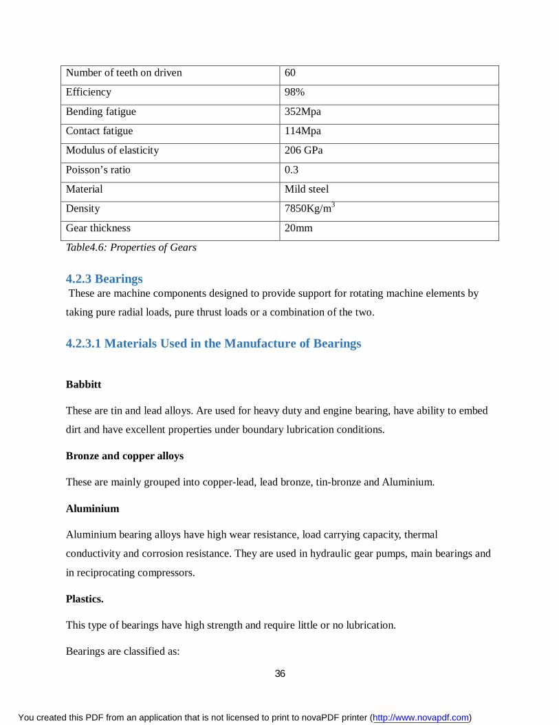
Table4.6: Properties of Gears
4.2.3 Bearings These are machine components designed to provide support for rotating machine elements by
taking pure radial loads, pure thrust loads or a combination of the two.
4.2.3.1 Materials Used in the Manufacture of Bearings
Babbitt
These are tin and lead alloys. Are used for heavy duty and engine bearing, have ability to embed
dirt and have excellent properties under boundary lubrication conditions.
Bronze and copper alloys
These are mainly grouped into copper-lead, lead bronze, tin-bronze and Aluminium.
Aluminium
Aluminium bearing alloys have high wear resistance, load carrying capacity, thermal
conductivity and corrosion resistance. They are used in hydraulic gear pumps, main bearings and
in reciprocating compressors.
Plastics.
This type of bearings have high strength and require little or no lubrication.
Bearings are classified as:
You created this PDF from an application that is not licensed to print to novaPDF printer (http://www.novapdf.com)
37
Rolling contact bearings.
These are of three main types namely ball bearings, roller bearings and needle bearings. The load
is transferred through rolling elements such as balls, needles, straight tapered cylinders and
rollers.
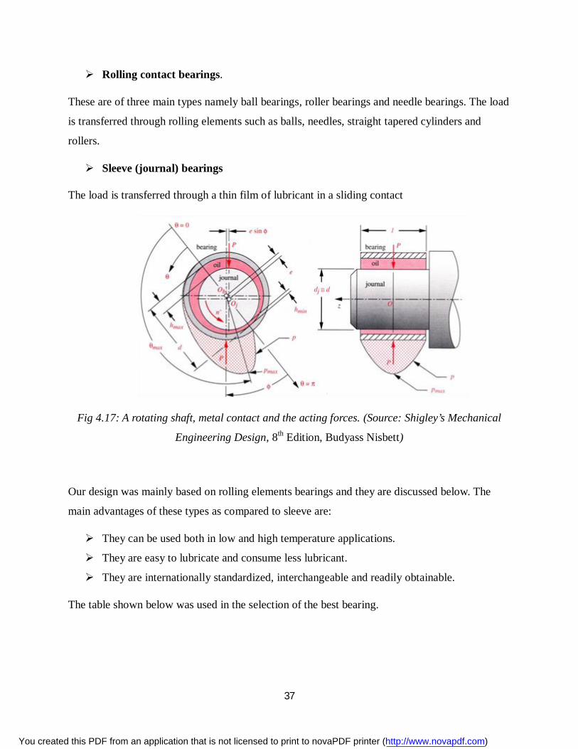
Sleeve (journal) bearings
The load is transferred through a thin film of lubricant in a sliding contact
Fig 4.17: A rotating shaft, metal contact and the acting forces. (Source: Shigley’s Mechanical
Engineering Design, 8th Edition, Budyass Nisbett)
Our design was mainly based on rolling elements bearings and they are discussed below. The
main advantages of these types as compared to sleeve are:
They can be used both in low and high temperature applications.
They are easy to lubricate and consume less lubricant.
They are internationally standardized, interchangeable and readily obtainable.
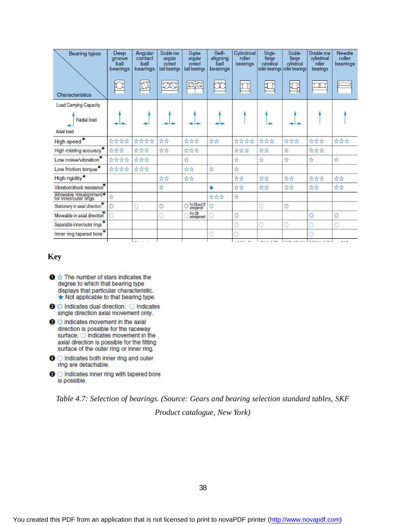
The table shown below was used in the selection of the best bearing.
You created this PDF from an application that is not licensed to print to novaPDF printer (http://www.novapdf.com)
38
Key
Table 4.7: Selection of bearings. (Source: Gears and bearing selection standard tables, SKF
Product catalogue, New York)
You created this PDF from an application that is not licensed to print to novaPDF printer (http://www.novapdf.com)
39
4.2.3.2 Types of Bearings
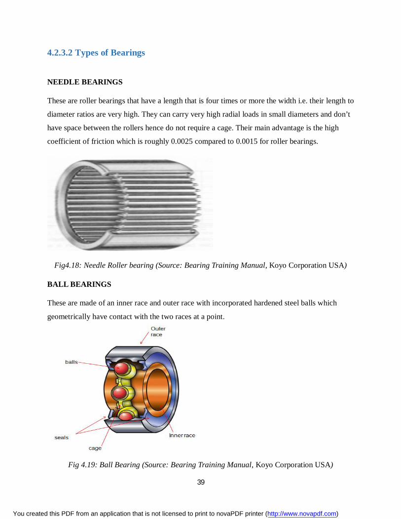
NEEDLE BEARINGS
These are roller bearings that have a length that is four times or more the width i.e. their length to
diameter ratios are very high. They can carry very high radial loads in small diameters and don’t
have space between the rollers hence do not require a cage. Their main advantage is the high
coefficient of friction which is roughly 0.0025 compared to 0.0015 for roller bearings.
Fig4.18: Needle Roller bearing (Source: Bearing Training Manual, Koyo Corporation USA)
BALL BEARINGS
These are made of an inner race and outer race with incorporated hardened steel balls which
geometrically have contact with the two races at a point.
Fig 4.19: Ball Bearing (Source: Bearing Training Manual, Koyo Corporation USA)
You created this PDF from an application that is not licensed to print to novaPDF printer (http://www.novapdf.com)
40
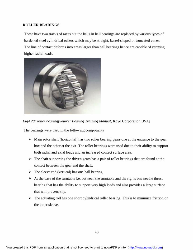
ROLLER BEARINGS
These have two tracks of races but the balls in ball bearings are replaced by various types of
hardened steel cylindrical rollers which may be straight, barrel-shaped or truncated cones.
The line of contact deforms into areas larger than ball bearings hence are capable of carrying
higher radial loads.
Fig4.20: roller bearing(Source: Bearing Training Manual, Koyo Corporation USA)
The bearings were used in the following components
Main rotor shaft (horizontal) has two roller bearing gears one at the entrance to the gear
box and the other at the exit. The roller bearings were used due to their ability to support
both radial and axial loads and an increased contact surface area.
The shaft supporting the driven gears has a pair of roller bearings that are found at the
contact between the gear and the shaft.
The sleeve rod (vertical) has one ball bearing.
At the base of the turntable i.e. between the turntable and the rig, is one needle thrust
bearing that has the ability to support very high loads and also provides a large surface
that will prevent slip.
The actuating rod has one short cylindrical roller bearing. This is to minimize friction on
the inner sleeve.
You created this PDF from an application that is not licensed to print to novaPDF printer (http://www.novapdf.com)
41
4.3 TAIL DESIGN The tail of the windmill is on the opposite side if the rotor assembly. The tail has two primary
functions:
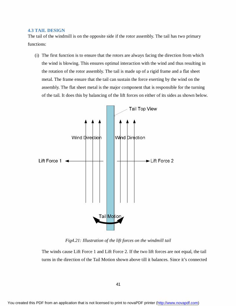
(i) The first function is to ensure that the rotors are always facing the direction from which
the wind is blowing. This ensures optimal interaction with the wind and thus resulting in
the rotation of the rotor assembly. The tail is made up of a rigid frame and a flat sheet
metal. The frame ensure that the tail can sustain the force exerting by the wind on the
assembly. The flat sheet metal is the major component that is responsible for the turning
of the tail. It does this by balancing of the lift forces on either of its sides as shown below.
Fig4.21: Illustration of the lift forces on the windmill tail
The winds cause Lift Force 1 and Lift Force 2. If the two lift forces are not equal, the tail
turns in the direction of the Tail Motion shown above till it balances. Since it’s connected
You created this PDF from an application that is not licensed to print to novaPDF printer (http://www.novapdf.com)
42
to the gear box, it will consequently turn the rotor assembly till it faces the direction of
wind.
(ii) The second function of the tail is to balance the moments that are caused by the rotor
assembly. If this moment is not balanced out, it might lead to the eventual failure at the
turntable.
To get the ideal dimensions for the tail, calculation of moments in the Windmill structure was
done as illustrated below:
4.3.1 Calculations of Moments The following are the basic equations that govern the calculation of moments.
푉표푙푢푚푒 = 퐶푟표푠푠 푆푒푐푡푖표푛푎푙 퐴푟푒푎 × 퐵푟푒푎푑푡ℎ
푉 = 퐴 × 푏 m3 …………………………………. (4.3)
푀푎푠푠 = 퐷푒푛푠푖푡푦 × 푉표푙푢푚푒
푀 = 휌 × 푉Kg ………………………………. (4.4)
푀표푚푒푛푡 = 퐹표푟푐푒 × 퐷푖푠푡푎푛푐푒
But: 퐹표푟푐푒 = 푀푎푠푠 × 퐺푟푎푣푖푡푎푡푖표푛푎푙 퐴푐푐푒푙푒푟푎푡푖표푛
퐹 = 푚푔 N ………………………………… (4.5)
∴ 푀표푚푒푛푡 = 푚푔 × 푑 Nm ………………………………. (4.6)
The windmill components that contributed to the bending moments were made of Mild Steel
whose density is 7850 kg/m3.
4.3.1.1 Anticlockwise Moments
(i) Blades
푉표푙푢푚푒 =214452.152
1000 × 1.465 × 10 × 24 = 7.5401 × 10 푚
You created this PDF from an application that is not licensed to print to novaPDF printer (http://www.novapdf.com)
43
푀푎푠푠 = 7850 × 7.5401 × 10 = 59.1901 푘푔
푀표푚푒푛푡 = 59.1901 × 9.81 × 0.447 = ퟐퟓퟗ.ퟓퟓퟐퟔ 푵풎
(ii) Side Blocks (On main shaft)
푉표푙푢푚푒 =14823.416
1000 × 13 × 10 = 1.9270 × 10 푚
푀푎푠푠 = 7850 × 1.9270 × 10 = 1.5127 푘푔
푀표푚푒푛푡 = (1.5127 × 9.81 × 0.491) + (1.5127 × 9.81 × 0.39) = ퟏퟑ.ퟎퟕퟑퟕ 푵풎
(iii) Inner Ring
푇표푡푎푙 퐶푟표푠푠 푆푒푐푡푖표푛푎푙 퐴푟푒푎 = (31612.223 + 1023.2 + 2234.194 + 4683.324)
= 39552.941 푚푚
푉표푙푢푚푒 =39552.941
1000 × 2.5 × 10 × 8 = 7.9106 × 10 푚
푀푎푠푠 = 7850 × 7.9106 × 10 = 6.2098 푘푔
푀표푚푒푛푡 = 6.2098 × 9.81 × 0.447 = ퟐퟕ.ퟐퟑퟎퟓ 푵풎
(iv) Outer Ring
푉표푙푢푚푒 =11281.459
1000 × 0.5 = 5.6407 × 10 푚
푀푎푠푠 = 7850 × 5.6407 × 10 = 4.4280 푘푔
푀표푚푒푛푡 = 4.4280 × 9.81 × 0.447 = ퟏퟗ.ퟒퟏퟕퟎ 푵풎
(v) Main Shaft
푉표푙푢푚푒 =507.053
1000 × 0.504 = 2.5555 × 10 푚
푀푎푠푠 = 7850 × 2.5555 × 10 = 2.0061 푘푔
푀표푚푒푛푡 = 2.0061 × 9.81 × 0.252 = ퟒ.ퟗퟓퟗퟑ 푵풎
You created this PDF from an application that is not licensed to print to novaPDF printer (http://www.novapdf.com)
44
TOTAL ANTICLOCKWISE MOMENTS:
= (259.5526 + 13.0737 + 27.2305 + 19.4170 + 4.9593)푁푚
= ퟑퟐퟒ.ퟐퟑퟑퟏ 푵풎
4.3.1.2 Clockwise Moments
(i) Main Shaft
푉표푙푢푚푒 =507.053
1000 × 0.496 = 2.5150 × 10 푚
푀푎푠푠 = 7850 × 2.5150 × 10 = 1.9743 푘푔
푀표푚푒푛푡 = 1.9743 × 9.81 × 0.248 = ퟒ.ퟖퟎퟑퟐ 푵풎
(ii) Sheet Metal
푉표푙푢푚푒 = 1 × 0.5 × 1.56 × 10 = 5.5836 × 10 푚
푀푎푠푠 = 7850 × 5.5836 × 10 = 4.3831 푘푔
푀표푚푒푛푡 = 4.3831 × 9.81 × 1.75 = ퟕퟓ.ퟐퟒퟕퟐ 푵풎
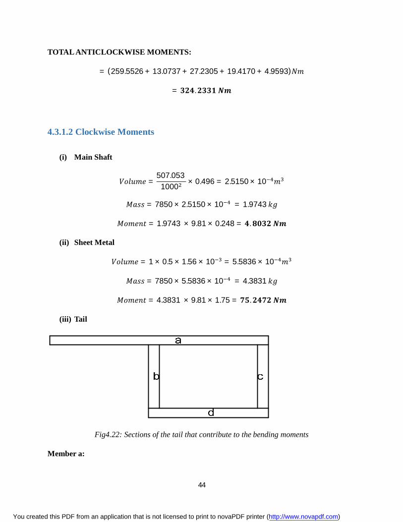
(iii) Tail
Fig4.22: Sections of the tail that contribute to the bending moments
Member a:
You created this PDF from an application that is not licensed to print to novaPDF printer (http://www.novapdf.com)
45
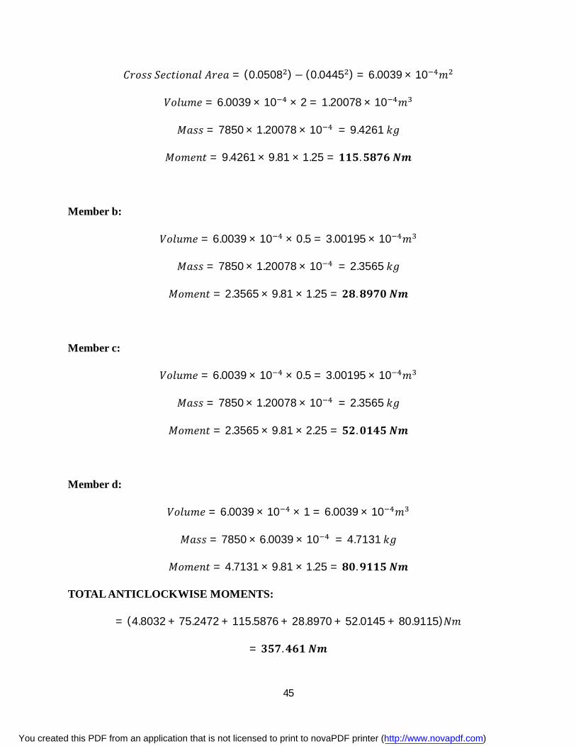
퐶푟표푠푠 푆푒푐푡푖표푛푎푙 퐴푟푒푎 = (0.0508 )− (0.0445 ) = 6.0039 × 10 푚
푉표푙푢푚푒 = 6.0039 × 10 × 2 = 1.20078 × 10 푚
푀푎푠푠 = 7850 × 1.20078 × 10 = 9.4261 푘푔
푀표푚푒푛푡 = 9.4261 × 9.81 × 1.25 = ퟏퟏퟓ.ퟓퟖퟕퟔ 푵풎
Member b:
푉표푙푢푚푒 = 6.0039 × 10 × 0.5 = 3.00195 × 10 푚
푀푎푠푠 = 7850 × 1.20078 × 10 = 2.3565 푘푔
푀표푚푒푛푡 = 2.3565 × 9.81 × 1.25 = ퟐퟖ.ퟖퟗퟕퟎ 푵풎
Member c:
푉표푙푢푚푒 = 6.0039 × 10 × 0.5 = 3.00195 × 10 푚
푀푎푠푠 = 7850 × 1.20078 × 10 = 2.3565 푘푔
푀표푚푒푛푡 = 2.3565 × 9.81 × 2.25 = ퟓퟐ.ퟎퟏퟒퟓ 푵풎
Member d:
푉표푙푢푚푒 = 6.0039 × 10 × 1 = 6.0039 × 10 푚
푀푎푠푠 = 7850 × 6.0039 × 10 = 4.7131 푘푔
푀표푚푒푛푡 = 4.7131 × 9.81 × 1.25 = ퟖퟎ.ퟗퟏퟏퟓ 푵풎
TOTAL ANTICLOCKWISE MOMENTS:
= (4.8032 + 75.2472 + 115.5876 + 28.8970 + 52.0145 + 80.9115)푁푚
= ퟑퟓퟕ.ퟒퟔퟏ 푵풎
You created this PDF from an application that is not licensed to print to novaPDF printer (http://www.novapdf.com)
46
The extra clockwise moment (33.2279 Nm) is there to cancel out the moments that are generated
by the support fittings and welds that are on the rotor assembly.
4.4 RIG DESIGN The rig design is based on an existing rig that is of height 5.5 m. However due to safety reasons
and rotor assembly dimensions, an extra height of 2 m is required.
In the design of the extra 2 meters, a number of design consideration had to be factored:
(i) The first and most important design consideration is that the rig had to support the weight
of the rotor, gear box and tail assembly. To achieve this, the frame of the tower had to be
of a metal with the ideal strength properties.
(ii) The rotor, gear box and tail assemblies generated both clockwise and anticlockwise
moments. Though the tail primarily balances these moments, the rig design had to be
rigid enough to also ensure that it could withstand such moments. This meant that in
addition to the material properties, the joining processes that had to be carried out on the
rig members had to provide sufficient strength as well.
(iii)The rig had to stand on its own. This implies that the design had to be balanced. Any
imbalance would generate a moment that would also weigh down on the base of the rig.
Over time, this will result in fatigue failure of members that are experiencing the extra
stress.
For stability, three vertical members were used at the edges. They were inclined at an angle of
100 from the vertical axis. This results in the cross section reducing up the rig. The wide base
increase stability by lowering the center of gravity of the tower. A lower center of gravity
decreases the chance of the rig tipping over.
The three ‘legs’ are made of square section [1] of 1.5 inch and a thickness of ½ inch. The diagonal
members are for extra support and they are made of L shape Mild Steel [2] of 1.5 inch sides and
thickness 3/16 inches. This minimizes the stresses that might be induced as the rig resists the
wind.
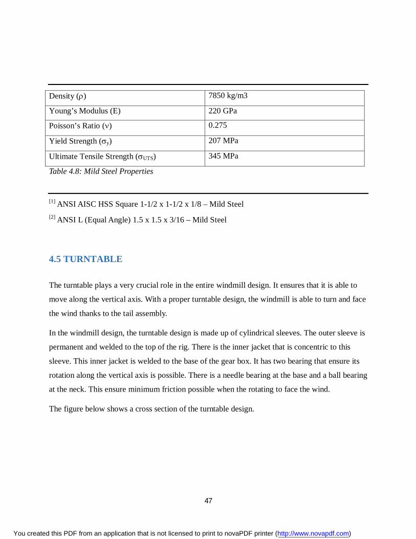
The Rig is made of Mild steel with the following properties:
You created this PDF from an application that is not licensed to print to novaPDF printer (http://www.novapdf.com)
47
Density () 7850 kg/m3
Young’s Modulus (E) 220 GPa
Poisson’s Ratio () 0.275
Yield Strength (y) 207 MPa
Ultimate Tensile Strength (UTS) 345 MPa
Table 4.8: Mild Steel Properties
[1] ANSI AISC HSS Square 1-1/2 x 1-1/2 x 1/8 – Mild Steel [2] ANSI L (Equal Angle) 1.5 x 1.5 x 3/16 – Mild Steel
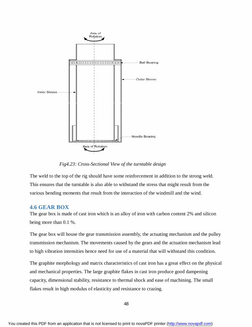
4.5 TURNTABLE
The turntable plays a very crucial role in the entire windmill design. It ensures that it is able to
move along the vertical axis. With a proper turntable design, the windmill is able to turn and face
the wind thanks to the tail assembly.
In the windmill design, the turntable design is made up of cylindrical sleeves. The outer sleeve is
permanent and welded to the top of the rig. There is the inner jacket that is concentric to this
sleeve. This inner jacket is welded to the base of the gear box. It has two bearing that ensure its
rotation along the vertical axis is possible. There is a needle bearing at the base and a ball bearing
at the neck. This ensure minimum friction possible when the rotating to face the wind.
The figure below shows a cross section of the turntable design.
You created this PDF from an application that is not licensed to print to novaPDF printer (http://www.novapdf.com)
48
Fig4.23: Cross-Sectional View of the turntable design
The weld to the top of the rig should have some reinforcement in addition to the strong weld.
This ensures that the turntable is also able to withstand the stress that might result from the
various bending moments that result from the interaction of the windmill and the wind.
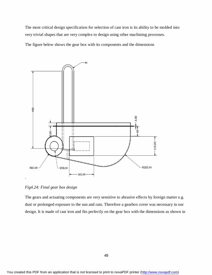
4.6 GEAR BOX The gear box is made of cast iron which is an alloy of iron with carbon content 2% and silicon
being more than 0.1 %.
The gear box will house the gear transmission assembly, the actuating mechanism and the pulley
transmission mechanism. The movements caused by the gears and the actuation mechanism lead
to high vibration intensities hence need for use of a material that will withstand this condition.
The graphite morphology and matrix characteristics of cast iron has a great effect on the physical
and mechanical properties. The large graphite flakes in cast iron produce good dampening
capacity, dimensional stability, resistance to thermal shock and ease of machining. The small
flakes result in high modulus of elasticity and resistance to crazing.
You created this PDF from an application that is not licensed to print to novaPDF printer (http://www.novapdf.com)
49
The most critical design specification for selection of cast iron is its ability to be molded into
very trivial shapes that are very complex to design using other machining processes.
The figure below shows the gear box with its components and the dimensions
.
Fig4.24: Final gear box design
The gears and actuating components are very sensitive to abrasive effects by foreign matter e.g.
dust or prolonged exposure to the sun and rain. Therefore a gearbox cover was necessary in our
design. It is made of cast iron and fits perfectly on the gear box with the dimensions as shown in
You created this PDF from an application that is not licensed to print to novaPDF printer (http://www.novapdf.com)
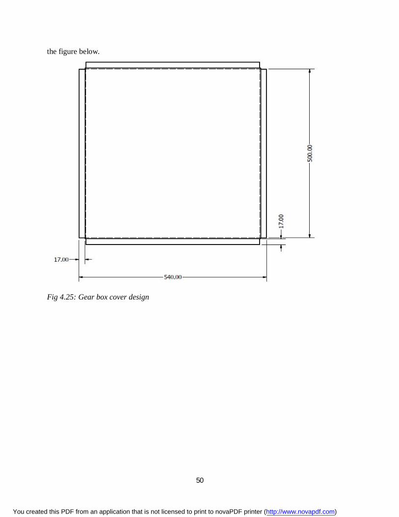
50
the figure below.
Fig 4.25: Gear box cover design
You created this PDF from an application that is not licensed to print to novaPDF printer (http://www.novapdf.com)
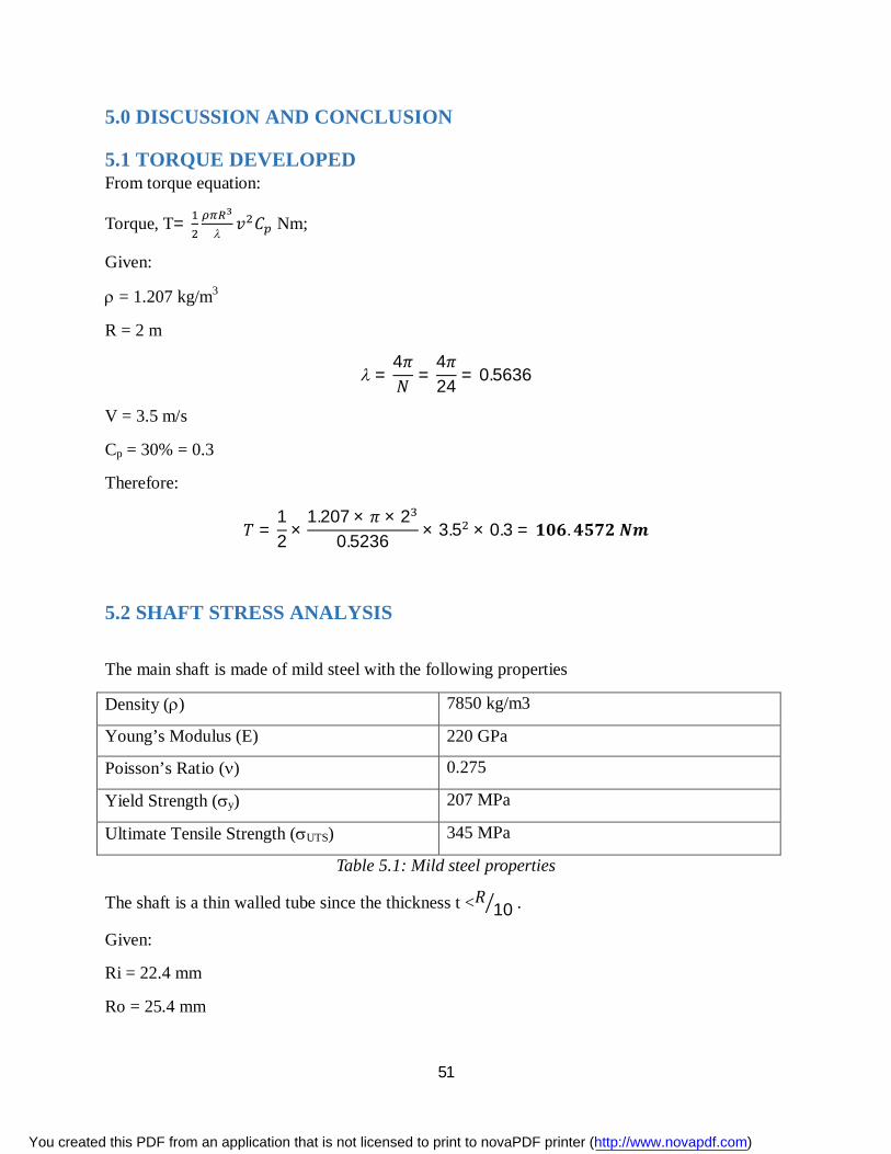
51
5.0 DISCUSSION AND CONCLUSION
5.1 TORQUE DEVELOPED From torque equation:
Torque, T=
푣 퐶 Nm;
Given:
= 1.207 kg/m3
R = 2 m
=4휋푁 =
4휋24 = 0.5636
V = 3.5 m/s
Cp = 30% = 0.3
Therefore:
푇 =12 ×
1.207 × 휋 × 20.5236 × 3.5 × 0.3 = ퟏퟎퟔ.ퟒퟓퟕퟐ 푵풎
5.2 SHAFT STRESS ANALYSIS
The main shaft is made of mild steel with the following properties
Density () 7850 kg/m3
Young’s Modulus (E) 220 GPa
Poisson’s Ratio () 0.275
Yield Strength (y) 207 MPa
Ultimate Tensile Strength (UTS) 345 MPa
Table 5.1: Mild steel properties
The shaft is a thin walled tube since the thickness t <푅 10 .
Given:
Ri = 22.4 mm
Ro = 25.4 mm
You created this PDF from an application that is not licensed to print to novaPDF printer (http://www.novapdf.com)
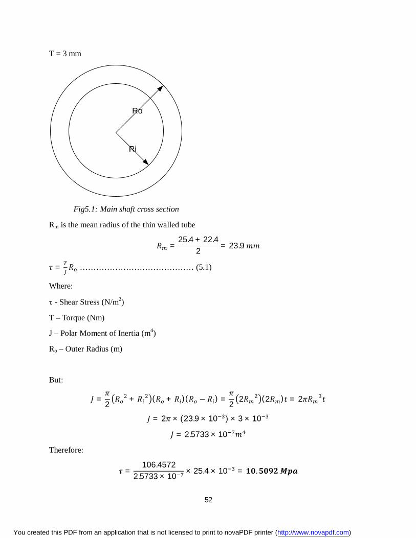
52
T = 3 mm
Ri
Ro
Fig5.1: Main shaft cross section
Rm is the mean radius of the thin walled tube
푅 =25.4 + 22.4
2 = 23.9 푚푚
휏 = 푅 …………………………………… (5.1)
Where:
- Shear Stress (N/m2)
T – Torque (Nm)
J – Polar Moment of Inertia (m4)
Ro – Outer Radius (m)
But:
퐽 =휋2 푅 + 푅 (푅 + 푅 )(푅 − 푅 ) =
휋2 2푅 (2푅 )푡 = 2휋푅 푡
퐽 = 2휋 × (23.9 × 10 ) × 3 × 10
퐽 = 2.5733 × 10 푚
Therefore:
휏 =106.4572
2.5733 × 10 × 25.4 × 10 = ퟏퟎ.ퟓퟎퟗퟐ 푴풑풂
You created this PDF from an application that is not licensed to print to novaPDF printer (http://www.novapdf.com)
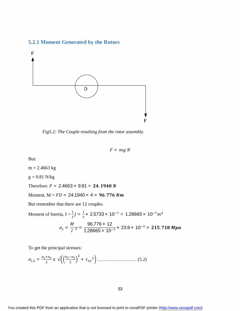
53
5.2.1 Moment Generated by the Rotors
Fig5.2: The Couple resulting from the rotor assembly.
퐹 = 푚푔 푁
But:
m = 2.4663 kg
g = 9.81 N/kg
Therefore: 퐹 = 2.4663 × 9.81 = ퟐퟒ.ퟏퟗퟒퟎ 푵
Moment, M = 퐹퐷 = 24.1940 × 4 = ퟗퟔ.ퟕퟕퟔ 푵풎
But remember that there are 12 couples.
Moment of Inertia, I = 퐽 = × 2.5733 × 10 = 1.28665 × 10 푚
휎 =푀퐼 푦 =
96.776 × 121.28665 × 10 × 23.9 × 10 = ퟐퟏퟓ.ퟕퟏퟖ 푴풑풂
To get the principal stresses:
휎 , = ± √ + 휏 ……………………. (5.2)
You created this PDF from an application that is not licensed to print to novaPDF printer (http://www.novapdf.com)
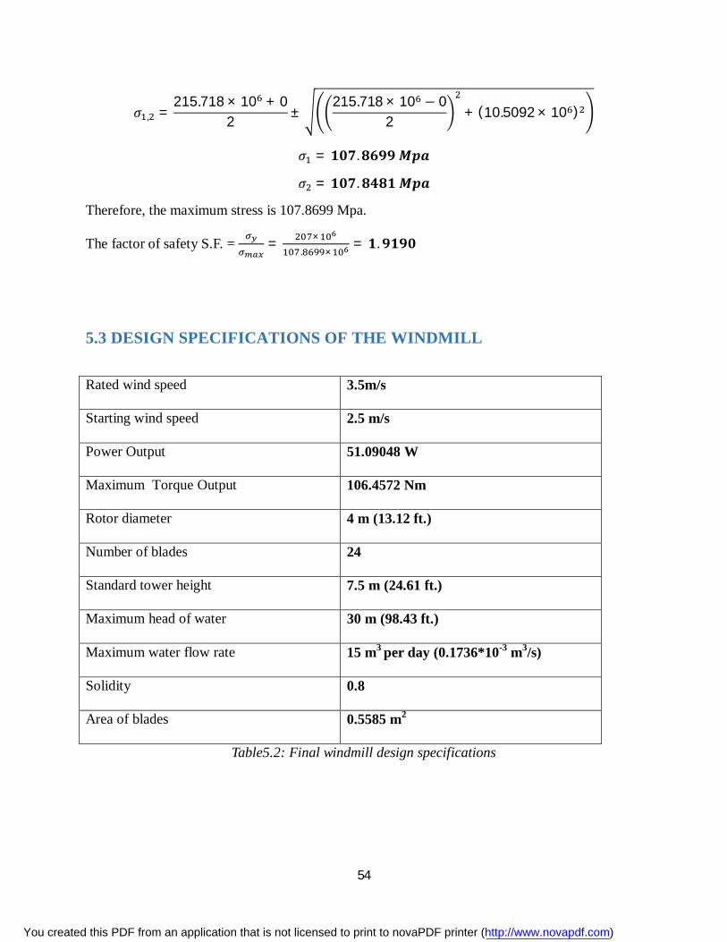
54
휎 , =215.718 × 10 + 0
2 ±215.718 × 10 − 0
2 + (10.5092 × 10 )
휎 = ퟏퟎퟕ.ퟖퟔퟗퟗ 푴풑풂
휎 = ퟏퟎퟕ.ퟖퟒퟖퟏ 푴풑풂
Therefore, the maximum stress is 107.8699 Mpa.
The factor of safety S.F. = = ×. ×
= ퟏ.ퟗퟏퟗퟎ
5.3 DESIGN SPECIFICATIONS OF THE WINDMILL
Rated wind speed 3.5m/s
Starting wind speed 2.5 m/s
Power Output 51.09048 W
Maximum Torque Output 106.4572 Nm
Rotor diameter 4 m (13.12 ft.)
Number of blades 24
Standard tower height 7.5 m (24.61 ft.)
Maximum head of water 30 m (98.43 ft.)
Maximum water flow rate 15 m3 per day (0.1736*10-3 m3/s)
Solidity 0.8
Area of blades 0.5585 m2
Table5.2: Final windmill design specifications
You created this PDF from an application that is not licensed to print to novaPDF printer (http://www.novapdf.com)
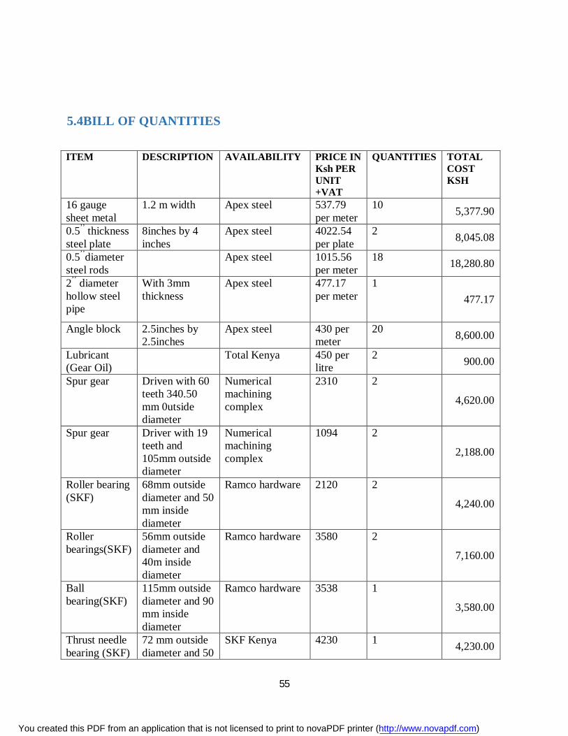
55
5.4BILL OF QUANTITIES
ITEM DESCRIPTION AVAILABILITY PRICE IN Ksh PER UNIT +VAT
QUANTITIES TOTAL COST KSH
16 gauge sheet metal
1.2 m width Apex steel 537.79 per meter
10 5,377.90
0.5’’ thickness steel plate
8inches by 4 inches
Apex steel 4022.54 per plate
2 8,045.08
0.5’’diameter steel rods
Apex steel 1015.56 per meter
18 18,280.80
2’’ diameter hollow steel pipe
With 3mm thickness
Apex steel 477.17 per meter
1 477.17
Angle block 2.5inches by 2.5inches
Apex steel 430 per meter
20 8,600.00
Lubricant (Gear Oil)
Total Kenya 450 per litre
2 900.00
Spur gear Driven with 60 teeth 340.50 mm 0utside diameter
Numerical machining complex
2310 2
4,620.00
Spur gear Driver with 19 teeth and 105mm outside diameter
Numerical machining complex
1094 2
2,188.00
Roller bearing (SKF)
68mm outside diameter and 50 mm inside diameter
Ramco hardware 2120 2
4,240.00
Roller bearings(SKF)
56mm outside diameter and 40m inside diameter
Ramco hardware 3580 2
7,160.00
Ball bearing(SKF)
115mm outside diameter and 90 mm inside diameter
Ramco hardware 3538 1
3,580.00
Thrust needle bearing (SKF)
72 mm outside diameter and 50
SKF Kenya 4230 1 4,230.00
You created this PDF from an application that is not licensed to print to novaPDF printer (http://www.novapdf.com)
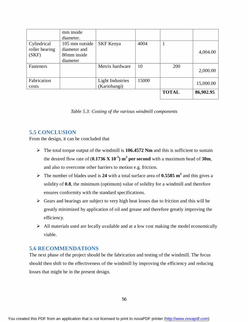
56
mm inside diameter.
Cylindrical roller bearing (SKF)
105 mm outside diameter and 80mm inside diameter
SKF Kenya 4004 1
4,004.00
Fasteners Metrix hardware 10 200 2,000.00
Fabrication costs
Light Industries (Kariobangi)
15000 15,000.00
TOTAL 86,902.95
Table 5.3: Costing of the various windmill components
5.5 CONCLUSION From the design, it can be concluded that
The total torque output of the windmill is 106.4572 Nm and this is sufficient to sustain
the desired flow rate of (0.1736 X 10⁻³) m3 per second with a maximum head of 30m,
and also to overcome other barriers to motion e.g. friction.
The number of blades used is 24 with a total surface area of 0.5585 m2 and this gives a
solidity of 0.8, the minimum (optimum) value of solidity for a windmill and therefore
ensures conformity with the standard specifications.
Gears and bearings are subject to very high heat losses due to friction and this will be
greatly minimized by application of oil and grease and therefore greatly improving the
efficiency.
All materials used are locally available and at a low cost making the model economically
viable.
5.6 RECOMMENDATIONS The next phase of the project should be the fabrication and testing of the windmill. The focus
should then shift to the effectiveness of the windmill by improving the efficiency and reducing
losses that might be in the present design.
You created this PDF from an application that is not licensed to print to novaPDF printer (http://www.novapdf.com)
57
REFERENCES
1. Wind Power Plants: Fundamentals, Design, Construction and Operation, R. Gasch, J.
Twele, et al., Springer Verlag, 2012
2. Performance Test on Helical Savonius Rotor, S.B. Kedare, 2003.
3. Wind Power Fundamentals: Alex Kalmikov and Katherine Dykes With contributions from:
Kathy Araujo PhD Candidates, MIT Mechanical Engineering, Engineering Systems and
Urban Planning MIT Wind Energy Group &Renewable Energy Projects in Action
4. Wind pump handbook (pilot edition) prepared by S.K Tewari and R.P. Gupta, Tata Energy
Research Institute, 1982.
5. Thermodynamic and Transport Properties of Fluids SI Unitsarranged by G. F. C. Rogers and
Y. R. Mayhew Fifth Edition Blackwell Publishing, 1995, Oxford, U.K.
6. Water pumping design, NYANGASI, George Oduwo, 2012.
7. Kenya Wind Atlas, Kenya Meteorological Department, 2010.
8. Typical Microstructures of Cast MetalsG. Lambert, Ed, 2nd
ed., The Institute of British
Foundry men, 1996, p 47
9. Energy and the Environment, Ristinen, Robert A., Jack J. Kraushaar, New York: John Wiley
and Sons, Inc., 1999.
10. College Physics: Second Edition,Urone, Paul P.,California: Brooks/Cole, 2001.
11. Guided Tour on Wind Energy. 16 Oct. 2002 <www.windpower.org/tour/index.htm>.
12. The National Wind Technology Center (NWTC). 16 Oct. 2002 <www.nrel.gov/wind/>.
13. Power Generation Sources, Transferline Compressed Air Energy. Dr. Ben Enis, Dr Paul Lieberman, Irving Rubin, Duane Bergmann, Randy Dirlam, Septimus van der Linden.
14. Harnessing the Wind for Home Energy Mc Guain, Dermot (1978 Washington, DC: Garden Way Associates, Inc.
15. Energy into PowerSterland, E. G. (1967) Garden City, NY: Natural History Press 16. Home Wind Power (1978),U. S. Department of Energy Washington, DC 17. Bearing Training Manual,Koyo Corporation USA, JTEKT Group, USA.
18. Shigley’s Mechanical Engineering Design, 8th Edition, Budyass-Nisbett, McGraw-Hill
Primis, New York, USA.
You created this PDF from an application that is not licensed to print to novaPDF printer (http://www.novapdf.com)
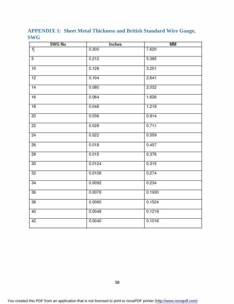
58
APPENDIX 1: Sheet Metal Thickness and British Standard Wire Gauge, SWG
You created this PDF from an application that is not licensed to print to novaPDF printer (http://www.novapdf.com)
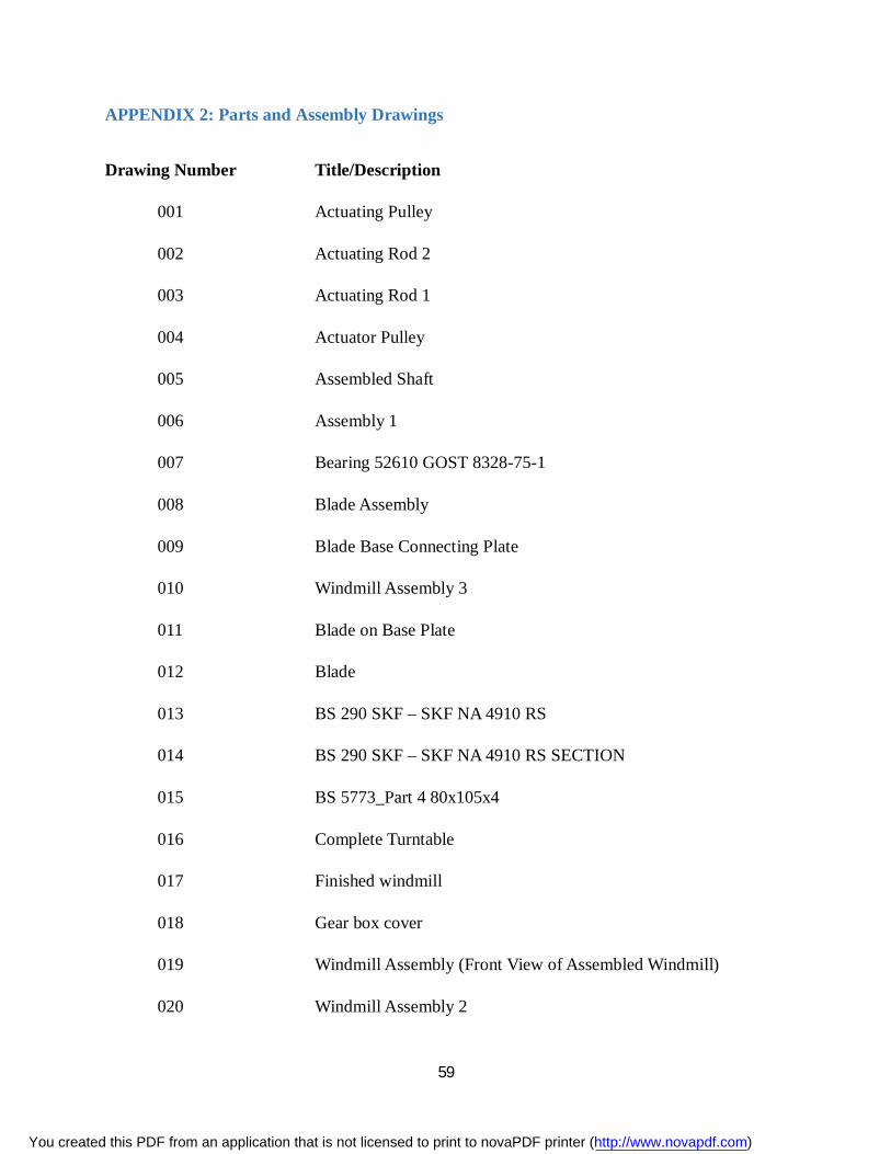
59
APPENDIX 2: Parts and Assembly Drawings
Drawing Number Title/Description
001 Actuating Pulley
002 Actuating Rod 2
003 Actuating Rod 1
004 Actuator Pulley
005 Assembled Shaft
006 Assembly 1
007 Bearing 52610 GOST 8328-75-1
008 Blade Assembly
009 Blade Base Connecting Plate
010 Windmill Assembly 3
011 Blade on Base Plate
012 Blade
013 BS 290 SKF – SKF NA 4910 RS
014 BS 290 SKF – SKF NA 4910 RS SECTION
015 BS 5773_Part 4 80x105x4
016 Complete Turntable
017 Finished windmill
018 Gear box cover
019 Windmill Assembly (Front View of Assembled Windmill)
020 Windmill Assembly 2
You created this PDF from an application that is not licensed to print to novaPDF printer (http://www.novapdf.com)

60
021 Gear Box
022 Gear shaft
023 Gear support arm
024 Gears Assembly
025 Main shaft
026 Outer Jacket 1
027 Outer Jacket Assembly 1
028 Pulley Connecting Rod
029 Outer Jacket Section
030 Outer Sleeve Section
031 Windmill Assembly
032 Rig Assembly
033 Rotor Assembly
034 Rotor Base plate
035 Side Blocks
036 SKF 2RZ61818-2RZ
037 SKF 2RZ61818-2RZ_Section
038 Spur Gears
039 Tail End Plate
040 Tail Frame
041 Turntable (Outer)
042 Windmill Assembly (Detail View of Windmill Assembly)
043 Windmill Assembly 1
You created this PDF from an application that is not licensed to print to novaPDF printer (http://www.novapdf.com)