Design and Development of a Laminated Fresnel Lens for...
76
CONTRACTOR REPORT SAND82-7127 Unlimited Release UC-63b Design and Development of a Laminated Fresnel Lens for Point Focus PV Systems - Phase II R. C. Hodge General Electric Company Advanced Energy Programs Department King of Prussia, PA 19406 Prepared by Sandia National Laboratories Albuquerque, New Mexico 87185 and Livermore, California 94550 for the United States Department of Energy under Contract DE-AC04-76DP00789 Printed December 1982 When printing a copy of any digitized SAND Report, you are required to update the markings to current standards.
Transcript of Design and Development of a Laminated Fresnel Lens for...

CONTRACTOR REPORT
SAND82-7127 Unlimited Release UC-63b
Design and Development of a Laminated Fresnel Lens for Point Focus PV Systems - Phase II
R. C. Hodge General Electric Company Advanced Energy Programs Department King of Prussia, PA 19406
Prepared by Sandia National Laboratories Albuquerque, New Mexico 87185 and Livermore, California 94550 for the United States Department of Energy under Contract DE-AC04-76DP00789
Printed December 1982
When printing a copy of any digitized SAND Report, you are required to update the
markings to current standards.

Issued by Sandia National Laboratories, operated for the United States Department of Energy by Sandia Corporation. NOTICE: This report was prepared 88 an account of work sponsored by an agency of the United States Government. Neither the United States Govern· ment nor any agency thereof, nor any of their employees, nor any of their contractors, subcontractors, or their employees, makes any warranty. express or imr.lied, or assumes any legal liability or responsibility for the accuracy, camp eteness, or usefulness of any information, apparatus, product, or process disclosed, or represents that its use would not infringe privately owned rights. Reference herein to any specific commercial product, process, or service by trade name, trademark, manufacturer, or otherwise, does not necessarily constitute or imply its endorsement, recommendation, or favoring by the United States Government, any agency thereof or any of their contractors or subcontractors. The views and opinions expressed herein do not necessarily state or reflect those of the United States Government, any agency thereof or any of their contractors or subcontractors.
Printed in the United States of America Available from National Technical Informat ion Service U.S. Department of Commerce 5285 Port Royal Road Springfield, VA 22161
NTIS price codes Printed copy: AM Microfiche copy: AOl

SAND82-7127 Unlimited Release
Printed December 1982
Distribution Category UC-63b
Design and Development of a Laminated Fresnel Lens for Point
Focus PV Systems - Phase II
R. C. Hodge General Electric Company
Advanced Energy Programs Department King of Prussia, PA 19406
Under Contract No. P062-9975
Abstract A laminated Glass-plastic lens parquet using injection molded point focus Fresnel
lenses is described. This report covers the second phase of a program aimed at investigating the cost effectiveness of a glass-plastic concentrator lens assembly. The first phase dealt with the development of a first generation lens design, the selection of the preferred glass coverplate and glass-to-Iens adhesive and initial injection molding lens molding trials. The second phase has dealt with the development of an improved lens design, a full size parquet lamination process, and a second group of injection molding lens molding trials.
FOREWORD
This final report is submitted to Sandia National Laboratories by the
General Electric Company. The final report summarizes the findings and work
performed in conjunction with the Sandia sponsored program "Design and
Development of a Laminated Fresnel Lens for Point Focus PV Systems" Sandia
P.O. 62-9975.
The work was performed by the Advanced Energy Programs Department of the
General Electric Company under the guidance of Mr. Charles Stillwell of
Sandia National Laboratories, Albuquerque. Mr. Ronald C. Hodge served as
program manager ~/ith key technical support from the following individuals:
J. Henkes - lens design development, H. Walters of Fresnel Optics - lens
master and control lens fabrication, E. Campagna - lamination process
development and G. Puckett - injection molding process engineer.
ii
• r

Section
1
2
3
4
5
6
7
INTRODUCT ION.
SU~1MARY . .
Objective Approach. Prototype Parquets.
TABLE OF CONTENTS
Lens Design •......... Lamination Process Development. Lamination Bond Integrity Studies Injection Molding Trials. Glass Superstrate
LENS DESIGN .....
Summary ..... . Design Development.
LAMINATION PROCESS DEVELOPMENT.
Objective . . . . . . . . . . . . Hard Tooling Approach with Vacuum Soft Tooling Approach •.....
Advantage of Soft Tooling ... Disadvantages of Soft Tooling ..
Hard Tooling Approach - Without Vacuum Prototype Parquet Hardware. . . . . Lamination Transmission Evaluations
BOND INTEGRITY STUDIES. . . . . .
. . . . . . . . . . (Baseline Process).
Summary . . . . . . . . . . .. ... Relative Humidity Environmental Analysis. Temperature - Humidity Cycling Procedures Delamination Studies ...... . Full Size Parquet Delamination .•
INJECTION MOLDING LENS DEVELOPMENT.
Outdoor Lens Testing ...... . Phase I vs. Phase II Results .. . Phase I I Lenses wi tha ,SecorJdary.
KEY RESULTS AND CONCLUSIONS
Summary . . . . . . . . . Key Resul ts . . . . . . . . . . . Improved Lens Design Development.
iii
Page
1
2
2 2 3 5 6 7 9 10
13
13 14
19
19 20 22 24 24 25 27 27
30
30 30 33 35 37
43
47 48 48
50
50 50 50

TABLE OF CONTENTS (Cont'd)
Section Page
Lami nation Process Development, . , • . . , . , . , • , 50 Development of Injection Molded Focus Fresnel Lenses. 51
Conclusions , , , . , , , . , 51
Appendix A - GE RTV 534-044 PROPERTY SHEET A-I
Appendix B - PARQUET LENS DRAWINGS . , , , B-1
Appendix C - SPECIFICATION SHEETS FOR'PROGRAM'S GLASS SUPERSTRATES C-l
Appendix D - BASELINE LAMINATION PROCESS FIXTURE DRAWING . . . . . D-l
iv

. ,
•
• •
Figure
1
2
3
4 5
6
7
8
9
10 11
12
13
14
15
16
17
18
19
20
21
22
23
23A
24
LIST OF ILLUSTRATIONS
Parquet Lens Concept. . . Prototype Parquet Lens. . .. Photograph of Void Areas on Lens. We Have Made Progress in Fresnel Facet Sharpness. Transmission Characteristics of the Program's Glass Superstrate Representative Sandia Lens Analyzer Output -GE Lens Design IV-c, 7.94 Focal Length Crossection of Lens Lamination Prototype 2 x 2 Hard Tooling Test Prototype Soft Tooling Mold. . Soft Tooling Approach. •
Fixture
Key Features of the Baseline Lamination Approach. Full Size Parquet Lamination Fixture .. Actual Lens Center-to-Lens Center Spacing Laminate Spectral Transmission Laminated Lens - Cell Efficiency Data .. Ambient Temperature - Relative Humidity Occurrence Profile. Psychometric Chart for Air at Barometric Pressure 29.92 In. Hq. .... ... Daily Thermal Cycle for Delamination Study. Temperature Cycling Results - Exp. Run No's 1, 2, 3, 4. Temperature Cycling Results - Exp. Run No's 5 and 6 • Temperature Cycle Results - Exp. Run No's 9 and 10. Representative Full Size Parquet Delaminations. Injection Molded Lens Test Set-up. . . . Processing Conditions Impacted Facet Sharpness. Injection Molded Lens Improvements. . .
v
Page
2
4 9
11
10
18
19
21
23
24
25
25
26 28
29
31
32
37
38
39
40
41
44 46
49

Table
1
2
3
4
5
6
7
8
9
10 11
LIST OF TABLES
Full Size Parquet Design Requirements Individual Fresnel Lens Requirements. Lens Data ............. . Design Summary Chart - GE Lens II Design (0.015 inch facets). GE Lens III Design (0.030 inch facets). GE Strawman Lens Design II. GE Strawman Lens Design IVc ..... . Delamination Test Matrix ....... . Relative Efficiency of Injection Molded Lenses. Summary of Injection Molded Lens Outdoor Testing. Injection Molded Lens Performance with a Secondary Ratio of GE Molded Lens Efficiency to Compression Molded Control ....... .
vi
Page
4
5
6
14
15
17 17 36
45 47
48
. ,
Section 1
Introduction
The objectives of this program were to evaluate the cost effectiveness of an
injection molded flat point focus Fresnel lens and to investigate the
feasibility and cost potential of a laminated glass-plastic lens parquet.
This report documents the results of the program which represents the second
phase of an earlier program. Phase I program dealt with the design of a
thin 6.65" sq. acrylic Fresnel lens laminated to a 7" sq. 3mm glass
superstrate which focused to a 0.61" square spot. [Juring Phase I a series
of injection molding trials were conducted in an attempt to duplicate the
lens performance commensurate with compression molding. Progress was made
with each molding trial; however, it was concluded that a new lens design
and series of molding experiments were needed. The results of the Phase I
effort are documented in Sandia Report number SANDBO-7l34.
The Phase II program has attempted to build on the molding and lens design
experience from the previous phase and to accomplish the following:
1) develop an improved lens design
2) demonstrate improved performance injection molded lenses
3) develop a parquet laminating process suitable to a variety of parquet sizes, i.e. 3x5, 5x5, 5x6.
-1-

Section 2
Summary
Objective. The basic objectives of the program were as follows:
1. Develop a new lens design that has improved transmission efficiency and better injection molding compatibility.
2. Develop a process for fabricating a glass superstrate-plastic lens laminate as shown in Figure 1.
OUTSIDE COVER GLASS
.............. -- (3 MM THICK)
INDIVIDUAL FRESNEL LENS
Figure 1. Parquet Lens Concept
~ 170 MM SQUARE
~
The outside cover glass serves as the principal lens mechanical support and
provides a durable lens cover. An array (parquet) of indivdually molded
square lenses are bonded to the glass with a thin clear adhesive maintaining II
a specified center-to-lens center spacing within +.010 •
Approach. The approach used to develop a better lens design involved an
analytical computer analysis coupled with close interaction with lens tool
and injection molding manufacturing people. Results from initial injection
molding trials in Phase I indicated a problem with inadequate lens facet
fill. As a result, engineers involved emphasized the development of
-2-
..

approaches (lens, mold, process) that would improve facet filling.
" During the program, two lens designs were developed: one with a .015 wide II II
facets, another with .030 wide facets. The .015 facetted lens had
" shallower facets, whereas the .030 facetted lens had one half as many
facets to fill. Mold inserts for both lens designs were fabricated and used
in the injection molding trials.
Sample lenses were tested and used to verify the basic lens design (flux
profile, efficiency potential) and to "fine tune" the injection molding
process.
Tne approach used to develop a parquet lamination process was basically a
trial and error method evaluating three different techniques. Individual
lens-glass specimens were used to evaluate the basic adhesive bond
integrity. Larger, 2x2 trial specimens were used to screen the three
candidate lamination schemes. Results from both GE and Sandia environmental
testing were used to evaluate the laminate bond integrity. Once the
preferred lamination technique was selected, a full size laminating fixture
was fabricated, and twenty prototype full size 6x5 parquet lenses assembled.
Prototype Parquets. A prototype full size parquet lens assembly is shown in
Figure 2.
As part of the program, twenty prototype parquets were made. A high
transmission soda lime glass was used as the lens superstrate. The adhesive
-3-

Figure 2. Prototype Parquet Lens
used was GE RTV 534-044. A property sheet for this material is found in
Appendix A. The individual Fresnel lenses were molded out of several
different acrylic materials. The compression molded control lenses were
made with Rohm-Haas V045; whereas a variety of materials were used during
the injection molding trials .
The basic design requirements for the full size parquet lens are shown in
Table 1.
Table 1. Full Size Parquet Uesign Requirements
•
•
Overall Size
Lens Center-to-Lens Center Spacing
II II II
34.50 1~0~030 x 41.20 .t.0.030
II II
6.70 :l:. 0.010
-4-
,.

• Lens Edge-to-Lens Edge Gap 0.050"
Hail Impact Resistance 1.00 " • diameter iceba11s at 73 ft/sec
• Temperature Cycling One -30 to 500 C cyc1e/2 hrs.
• Exposure Temperature Range -350 C to 650 C
• UV Exposure < 5% transmission degradation after 3OMW/cm2 for 300 hrs.
• Temperature-Humidity To Be Determined
A dral1i ng package for the parquet 1 ens ; s found in Append; x B.
Lens Design. The basic design requirements for the individual Fresnel
lenses are shown in Table 2.
Table 2. Individual Fresnel Lens Requirements
Individual Fresnel Lens Size
Distance From Lens to Focal P1 ane (cell)
Illumination Target Size
6.66" +.010" square -.020"
8.0" "F#1.2"
11 • 0.61 dlameter spot
Flux Distribution at Focal Plane Peaks < 2X lave.
Overall Solar Spectrum Lens Efficiency (AM1.5)
Lens Thickness
> 80%
II II
.040 -.080
The lens efficiency term relates to the percent of solar energy IIfocused" " within the required target area, in our case the target area is a 0.61
diameter spot. Design verification lenses were manufactured using
compression molding. These lenses were used as our IIcontrolll lenses for
comparison with the injection molded lenses.
-5-
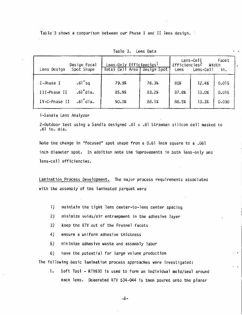
Tab1e"3 shows a comparison between our Phase I and II lens design.
Table 3. Lens Data
Lens-Cell Facet Des i gn Focal Lens-OnUL Efficiencies1 Efficiencies2 Width
Lens Design Spot Shape Tota 1 Ce 11 Area Design Spot Lens Lens-Ce 11 in.
I I -Phase I .61"sq 79.9% 76.3% 80% 12.4% 0.015
I I I-Ph ase II .61"dia. 85.9% 83.2% 87.8% 13.0% 0.015
I V -C-Phase II " .61 dia. 90.0% 88.1% 88.5% 13.3% 0.030
l-Sandia Lens Analyzer
2-0utdoor test using a Sandia designed .81 x .81 Strawman silicon cell masked to .61 in. dia.
Note the change in "focused" spot shape from a 0.61 inch square to a .061
inch diameter spot. In addition note the improvements in both lens-only and
lens-cell efficiencies.
Lamination Process Development. The major process requirements associated
with the assembly of the laminated parquet were
1 ) maintain the tight lens center-to-lens center spaci ng
2) minimize voids/air entrampment in the adhesive layer
3) keep the RTV out of the Fresnel facets
4) ensure a uniform adhesive thickness
5) minimize adhesive waste and assembly labor
6) have the potential for large volume production
The following basic lamination process approaches were investigated:
1. Soft Tool - RTV630 is used to form an individual mold/seal around
each lens. Deaerated RTV 534-044 is then poured onto the planar
-6-

side of the indivual Fresnel lenses and the glass cover is laid
down. The RTV630 does provide an excellent seal to keep the RTV
534-044 from filling the Fresnel facets, but the soft mold is not
reuseable and thus not practical.
2. Hard Tooling With Vacuum - Each lens is placed facet side down on
a flat aluminum plate. A gasket filled groove is locQted at the
perimeter of each lens position. Vacuum ports are machined into
the aluminum plate. Each lens is positioned onto the aluminum
plate. A vacuum is applied which draws the lenses down flush and
suppresses the gasket. A number of gaskets were tried.
Unfortunately, adequate lens edge sealing was not aChieved.
Parquets made with this approach consistently had slight amounts
of the bonding adhesive in their lens facets.
3. Hard Tooling Without Vacuum - This approach uses accurately
positioned studs in a flat fixture to position each lens. Molded
" in to the facet side of each lens is a small .065 diameter
indexing hole which mates to the fixture's studs. The bonding
adhesive is kept away from the facets by sealing each lens edge II II
with a thin (.002 ) narrow (.125 wide) transparent tape.
Testing at GE and Sandia confirm that the tape does not adversely
affect lens transmission efficiency. This approach was
subsequently selected as our baseline lamination process.
Lamination Bond Integrity Studies. During the program, GE has sent
glass-adhesive-plastic laminate specimens to Sandia for routine temperature
-7-

~ld ilUlnidity cycling. To date, the specimens have exhibited various degrees
of delamination. This has been a frustrating problem in that the RTV
experts at GE-Silicon Products Division maintain that technically our
material system of glass-RTV-acrylic should not delaminate under our
Lilennal-humidity conditions.
Tne delaminations in question range from an early uncured specimen, to II II
ec.ncJOIII oUIJDles ranging from 1/16 to 3/8 diameter, to small (0.060 .)
in') "void" areas particularly around our molded-in spacer feet.
i~oubleshooting of the early uncured specimen showed that the cause was a
t:lnclo!ll case of inadequate mixing of RTV534-044 part A and part B.
Subsequent specimens and lenses do not indicate any uncured resin.
TroLioleshooting of the random bubbles concluded that the bubble development
could be due to very small, visually undetectable pockets of entrapped air
'n the i{TV blend. With elevated temperature, these pockets then expand into
"i o.i b 1 e bubo I e s.
I:"oubleshooting of the small void areas appear to indicate that the
(elaminations are primarily due to insufficient primer application
';i\rticularly around the small lens spacer feet.
'1:8 twenty full size parquets were built paying special attention to the
,bo'le [jelamination prOblems. Results to date indicate that, for the most
J~'. the bubble problem has disappeared, but we are still finding small
(p1aminations or tears around the spacer feet, see Figure 3.
-8-

, -
Figure 3. Photograph of Void Areas on Lens
The sma 11 voi ds or tears do not show up on every 1 ens and when they do they
always seem to appear after the first few days of temperature cycling. Data
todate indicates that the voids do not seem to get any larger. .For example,
a full size parquet was placed outdoors. After four months of this exposure,
the voids had not gotten larger and their number had not increased. In
addition, the total area affected by the void condition represented only
0.02% of the total lens area . Whether this condition wil l continue to exist
is something that on ly time will tell. Several of the prototype lenses will
be placed outdoors by Sandia to monitor the delamin ation over an extended
period of time.
Injection Molding Trials. Over 900 6.66 inch squa re Fresnel lenses were
molded using a modified injection molding process. These molding trials
were part of a GE funded development effort. Per a GE and Sandia agreement,
representative injection molded lenses were delivered to Sandia for
-9-

z 0 (/) (/)
:2: VI Z <:( 0::: I-0\0
subsequent evaluations. In addition, ten of the twenty prototype parquets
were made with the injection molded lenses.
As stated, one of the major problems uncovered during our initial injection
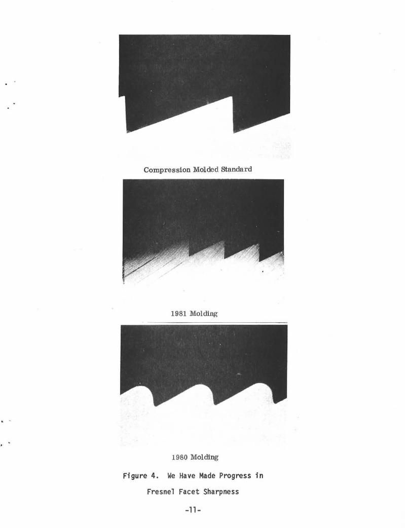
molding experiments was inadequate facet filling. As shown in Figure 4, we
made significant progress in this area during our second round of molding.
Glass Superstrate. Due to the long lead time and the high cost of low
quantity orders for Schott 6-270 glass, a search for an alternative glass
source was conducted. As a result of this survey, Solakleer (another low
iron soda lime glass) was selected. Figure 5 shows the transmission
characteristics for these two glasses as compared to regular soda lilne
glass.
'! 'l:~
90
80
70
60
50
40
30
20
10
300
Specification sheets may be found in Appendix C.
~:::::=====::::::::-- -- - - ------------ -
400 500 600
--- SOLAKLEER
____ SCHOTT 8270 SODA LIME
____ REGULAR SODA LIME (PPG)
GLASS THICKNESS: 0.125"
WAVELENGTH, NM
Figure 5. Transmission Characteristics of the Programs's
Glass Superstrate
-10-
t . "
Compression Molded Standard
1981 Molding
1980 Molding
Figure 4. We Have Made Progress in
Fresnel Facet Sharpness
-11-

Of the twenty prototype parquet lenses, ten were made with Schott glass
5uperstrates and ten with Solakleer glass superstrates.
-12-

Section 3
Lens Design
Summary. Soon after the second phase of the program got underway, a meeting
was held at Sandia to review the lessons learned from the previous injection
molding experiments. At this meeting, the following Fresnel lens design
considerations and parameters were discussed:
1. Reduce the number of facets
2. Increase F-number for higher efficiency
3. Constant-depth facets
4. Constant-curve facets
Of the above considerations, reducing the number of facets from our previous
design appeared to be the best way to improve lens efficiency. Our earlier
injection molding experiments had indicated that we were having difficulty in
completely filling the facet tips. By reducing the number of facets, we would
reduce the negative effect the inadequately filled facet tips had on lens
efficiency.
We decided to design two new lenses, one with 0.030 inch wide facets and
another with 0.015 inch wide facets. The 0.030 inch facetted lens would have
half as many facets as our Phase I 0.015 inch facetted design, whereas a new
0.015 inch facetted lens could be a thinner lens with half as deep facets as
the 0.030 inch facet design. During the lens design effort, several revisions
were made to both the 0.015 and 0.030 inch designs in order to optimize their
light distribution. Masters of the best designs were fabricated, and
proof-of-design lenses made and tested. Outdoor lens testing at Sandia
indicated that both lens designs were very similar with lens efficiencies of
88.5% for the 0.030 design and 85.6% for the 0.015 lens design.
-13-

Design Development. Two lens designs were developed: ]) an update of our
earlier Phase I 0.015 inch facet lens and 2) a new 0.030 inch facet design
based on theoretical and real data evaluations of the new 0.015 inch facet
lens. In the development of both lens designs, detailed computer analyses
were performed by C. St i llwe II of Sand i a before the masters were cut.
An updated 0.015 inch lens (lens II) design was generated and se~t to Sandia
for computer analysis. A summary of the Sandia analysis is provided in Table 4.
Table 4. Design Summary Chart GE Lens II Design (0.015 inch facets)
Facet Design
Tip Valley Draft Image Lens Concentrati on Width Radius Radius Angle Dia. Eff. (i n) (i n) (i n) (Dea) (i n) % Ave. Peak
.015 .001 .0005 2 .61 77.6 151 217
.015 .0005 .0005 2 .61 80.4 151 .3 288
As shown, the effect of going from a .0005 inch facet tip radius to a .001
inch tip radius is fairly significant, i.e. 3.4% efficiency loss. From this
analysis, an injection molded lens tip radius design goal of less than or
equal to .0006 inch was established. In addition, analysis of the predicted
light distribution indicated an improvement from the Phase I lens design.
The first 0.030 inch facet lens design (design III) was sent to Sandia for
computer analysis. A summary of this analysis is provided in Table 5.
-14-
. .

Facet Parameters
Tip Va 11 ey Radii Radi i ( in) (in)
.001 .0005
.001 .0005
.001 .0005
.002 .0005
.003 .0005
.003 .0005
.0001 .0001
.0001 .0001
.0001 .0001
.0001 .0001
Table 5. GE Lens III Design (0.030 inch facets)
Draft Image Lens Angle Dia. Eff (Deg) (in) (%)
2 .61 82.9 3 .61 82.18 4 .61 81.48 2 .61 80.3 2 .61 77 .3 2 .81 83.2
2 .61 86.7 3 .61 85.9 4 .61 85.2 2 .81 87
Concentration
Averaqe Peak
151 214 151.3 213 151.3 210 151 .3 206 151 .3 198 85.8 189
151 249 153.2 249 152.3 228 85.8 203
In this analysis, the effects of different facet radii and facet draft angles
were evaluated. From this analysis, we concluded that going to a 0.030 inch
facet reduces our sensitivity to "rounded" facet tips and that, if needed, we
could tolerate going to a four degree draft angle.
Computer analysis at Sandia indicated that Lens III had a slightly smaller
intensity profile than desired. It was then decided that revisions to lens
III would be made. One revision (IVa) attempted to reduce the "hole" in the
intensity profile, and one revision (IVb) attempted to open up the intensity
profile a bit.
Sandia evaluation of these revisions indicated that lens IVa had been opened
to the desired degree; however, IVb was overcompensated for and was now
slightly peaked in the center.
A final touch-up of the 0.030 inch facet design (IVc), that included elements
of the IVb modification, was made and sent to Sandia for evaluation. Based on
-15-

the Sandia computer analysis data, it was decided that lens IVc would be
selected as our best 0.030 inch facet design.
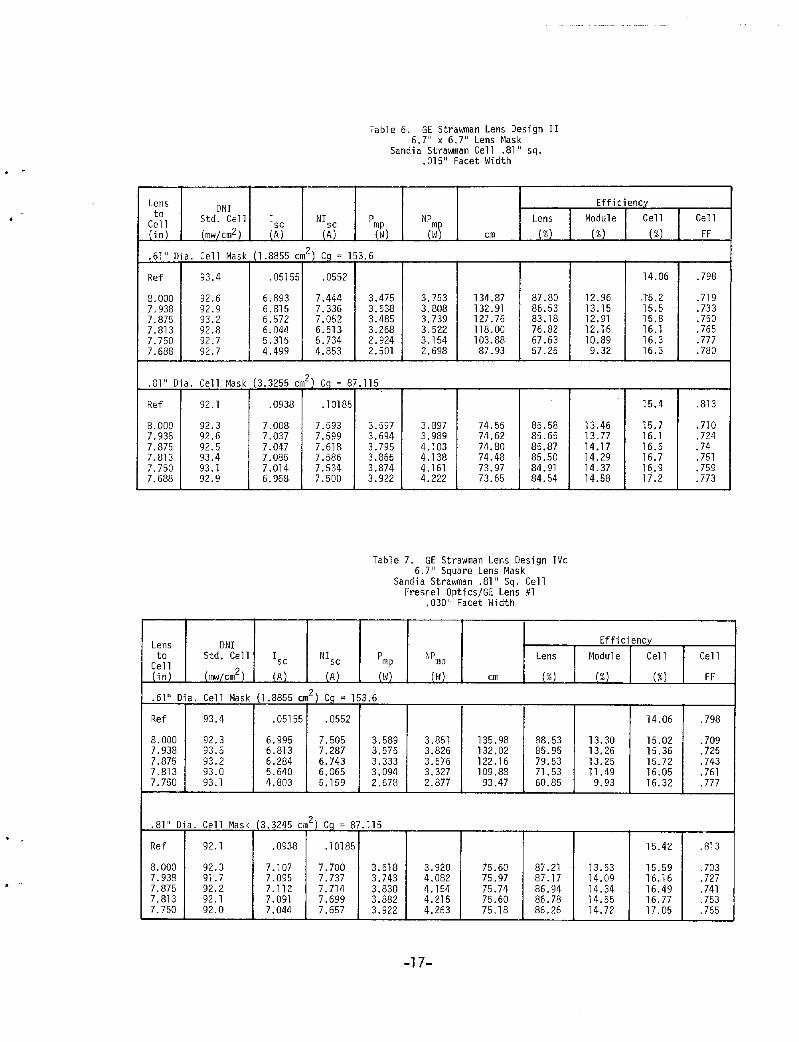
Masters were cut by Fresnel Optics of Rochester, New York, for both lens II
and IVc designs. Compression molded proof-of-design lenses for both designs
were sent to Sandia for testing. Tables 6 and 7 summarize outdoor test data
for lens designs II and IVc respectively. Representative Sandia,lens analyzer
test data for lens design IVc is provided in Figure 6.
From this test data, it was concluded that we had developed improved lens
designs. Inserts made from lens design II and IVc masters were then used in
the subsequent injection molding trials.
-16-
. "
Lens to
z~~l .6111 Di a.
Ref
8.000 7.938 7.875 7.813 7.750 7.688
. mil Dia.
Ref
8.000 7.938 7.875 7.813 7.750 7.688
Lens to
7~~1 .61" Dia.
Ref
8.000 7.938 7.875 7.813 7.750
. 81 11 Dia .
Ref
8.000 7.938 . . 7.875 7.813 7.750
DNI Std. Cell (m>J/cm2)
Ce 11 Mask
93.4
92.6 92.9 93.2 92.8 92.7 92.7
I (~)
NI (~)
Table 6. GE Strawman Lens Design II 6.7 11 x 6.7 11 Lens Mask
Sandia Strawman Cell .81" sq . . 015" Facet I;i dth
Pmp NP Lens '(1; ) (~) cm (%)
(1.8855 cm2) Cq = 153.6
.05155 .0552
6.893 7.444 3.475 3.753 134.87 87.80 6.815 7.336 3.538 3.808 132.91 86.53 6.572 7.052 3.485 3.739 127.76 83.18 6.044 6.513 3.268 3.522 118.00 76.82 5.315 5.734 2.924 3.154 103.88 67.63 4.499 4.853 2.501 2.698 87.93 57.25
Cell Mask (3.3255 cm2) C9 = 87.115
92.1
92.3 92.6 92.5 93.4 93.1 92.9
ONI Std. Cell
(mw/cm2)
Cell Mask
93.4
92.3 93.5 93.2 93.0 93.1
.0938 .10185
7.008 7.593 7.037 7.599 7.047 7.618 7.085 7.586 7.014 7.534 6.968 7.500
Isc N1sc
iAl (A)
3.597 3.897 74.55 85.58 3.694 3.989 74.62 85.65 3.795 4.103 74.80 85.87 3.865 4.138 74.48 85.50 3.874 4.161 73.97 84.91 3.922 4.222 73.65 84.54
Table 7. GE Strawman Lens Oesign IVc 6.7" Square Lens Mask
P mp
(I;)
Sandi a Strawman .81" Sq. Cell Fresnel Optics/GE Lens #1
.030" Facet Hidth
NPmp Lens
(i'l) cm (%)
(1.8855 cm2) Cq = 153.6
.05155 .0552
6.995 7.505 3.589 3.851 135.98 88.53 6.813 7.287 3.575 3.826 132.02 85.95 6.284 6.743 3.333 3.576 122.16 79.53 5.640 6.065 3.094 3.327 109.88 71. 53 4.803 5.159 2.678 2.877 93.47 60.85
Cell Mask (3.3245 cm2) Co = 87.115
92.1 .0938 .10185
92.3 7.107 7.700 3.618 3.920 75.60 87.21 91.7 7.095 7.737 3.743 4.082 75.97 87.17 92.2 7.112 7.714 3.830 4.154 75.74 86.94 92.1 7.091 7.699 3.882 4.215 75.60 86.78 92.0 7.044 7.657 3.922 4.263 75.18 86.26
-17-
Efficiency Modul e Cell Cell
(%) (%) FF
14.06 .798
12.96 .1"5.2 .719 13.15 15.5 .733 12.91 15.8 .750 12.16 16.1 .765 10.89 16.3 .777 9.32 16.3 .780
15.4 .813
13.46 15.7 .710 13.77 16.1 .724 14.17 16.5 .74 14.29 16.7 .751 14.37 16.9 .759 14.58 17.2 .773
Efficiency Module Cell Cell
(%) (%) FF
14.06 .798
13.30 15.02 .709 13.26 15.36 .725 13.25 15.72 .743 11.49 16.05 .761 9.93 16.32 .777
15.42 .813
13.53 15.59 .703 14.09 16.16 .727 14.34 16.49 .741 14.55 16.77 .753 14.72 17.05 .765

3-D PLOT OF FILE GEIV2
El - 25 Az .. 25 Scan Efficiency = 90.03~
3-D PLOT OF FOCUSED FLUX
X DIHENSIOIJ (Jr,)
i . . Ii . ~ " ~ ~ :
.; "'_ilIO;'l
.05<1
- 1",0
• lSI!
, .2~6
~
.3~e Z 0
.3B<l
"' Z
~ .,ue H
" .512 >-
_5'76
.eie
_""oj .1M
FOCUSED FLUX PLANAR VIEW
31iiJ.8
:321.2
;U:l_!I
0 ~ r ~4~ .11
" '" Z :;!I<4.1
" f-
~ 17S.4
Z W
" H2.i' e u
'" 187.1 a: cl "' 71_-'1
"5.7
... !
X DI,HENSION (In)
FOCUSED FLUX CROSS SECTION
PLOT or COHTOURSC-') 2 5 10 25 50 75 90
OF rILE GEI\lZ
Irr.agi:i cl i arr,ete r "" • 6 J0
Lens Eff lcienc .... 89. lOY.
Scan ef-fic:iency 8B.03:'7,
PLOT OF SLICES; 2 8 14 20 2"
or fILE GEIV2
mage Diarfleter-' : .618
Lens efficiency: Be.10%
Ave c~ncentratjQn -135.32
Scan E-ffic;e~cy 8£1.83%
!'-lax Bean cone = 856.83
Ave scan cone = 79.43
Fi gure 6. Representative Sandia Lens Analyzer Output 11
GE Lens Design IV-c, 7.94 Focal Length
-18-

Section 4
Lamination Process Development
Objective. The Objective of this phase of the project was to develop a
process for fabricating a Fresnel lens parquet. The parquet measures 41.2 x
34.5 inches and contains an array of 6 lenses by 5 lenses with each lens being
6.66 inch square. Figure 7 illustrates the materials used in fabricating the parquet.
Figure 7. Crossection of Lens Lamination
The material which causes the most difficulty during the fabricating of the
parquet is the RTV bonding adhesive (534-044). This RTV is a low viscosity
liquid and will readily flow through any minute crevice or opening in its path
such as the open facets found along the perimeter of the Fresnel lens. As a
-19-
result, a major objective of the lamination process development effort was to
identify a process that would prevent the RTV from flowing into the lens
facets. In addition, the process had to address the need to accurately control
the lens center-to-lens center spacing of 6.700 + .010 inch. In addition, the
process also had to minimize the occurrence of voids or air bubbles in the
adhesive layer, ensure uniform adhesive thickness, and minimize adhesive waste
and assembly labor. Finally, the process needed to be adaptable ~o potential
large production runs.
The following paragraphs describe the various process approaches that were
investigated:
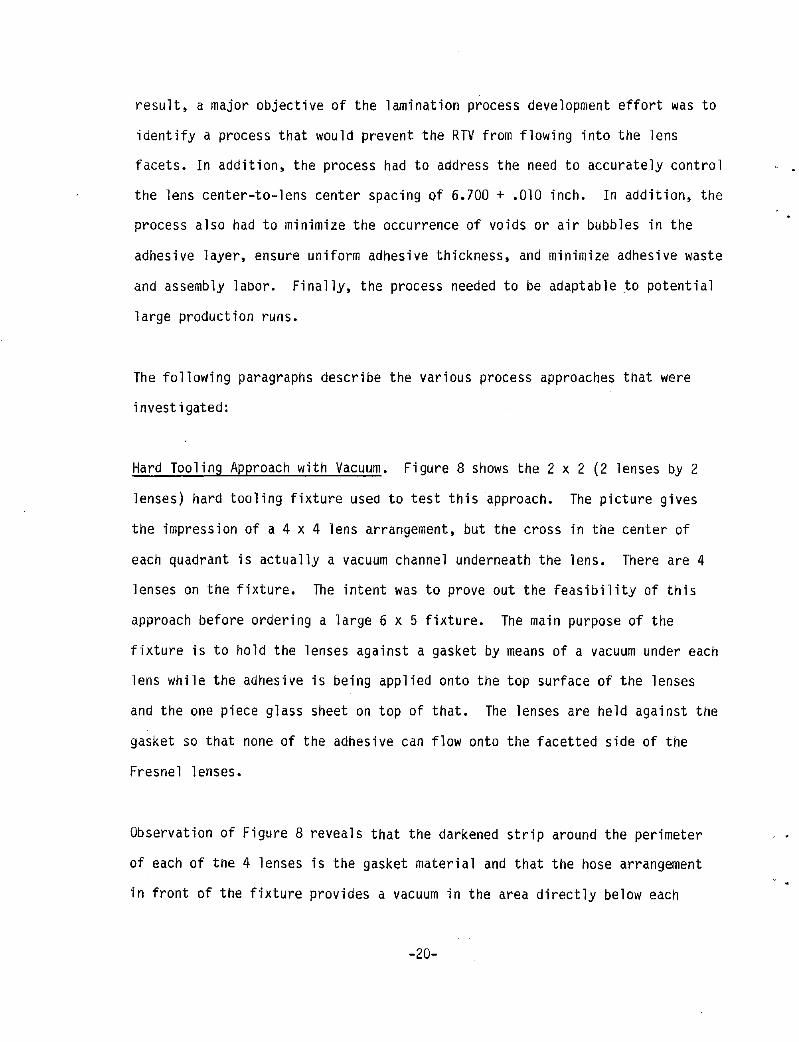
Hard Tooling Approach with Vacuum. Figure 8 shows the 2 x 2 (2 lenses by 2
lenses) hard tooling fixture used to test this approach. The picture gives
the impression of a 4 x 4 lens arrangement, but the cross in the center of
each quadrant is actually a vacuum channel underneath the lens. There are 4
lenses on the fixture. The intent was to prove out the feasibility of this
approach before ordering a large 6 x 5 fixture. The main purpose of the
fixture is to hold the lenses against a gasket by means of a vacuum under each
lens while the adhesive is being applied onto the top surface of the lenses
and the one piece glass sheet on top of that. The lenses are held against the
gasket so that none of the adhesive can flow onto the facetted side of the
Fresnel lenses.
Observation of Figure 8 reveals that the darkened strip around the perimeter
of each of the 4 lenses is the gasket material and that the hose arrangement
in front of the fixture provides a vacuum in the area directly below each
-20-

Figure 8. Prototype 2x2 Hard Tooling Test Fixture
individual lens. Prior to pouring the adhesive over the top of the 4 lenses,
they are pulled down against the gasket material when the vacuum is activated.
It should be remembered that the facets on the underside of the lenses come
out to the 4 sides of each lens. 'This means that in order to form a complete
seal, the gasket material must conform exactly to the shape of the facets.
This is difficult to accomplish , since the facets have very sharp features.
This has been the main difficulty encountered with the hard fixture approach.
Without this conformity between facet and gasket, the suction action of the
vacuum under each of the lenses pulls adhesive through the unprotected facets
onto the underside of the lenses, which is supposed to be kept free of
adhesive.
-2 1-
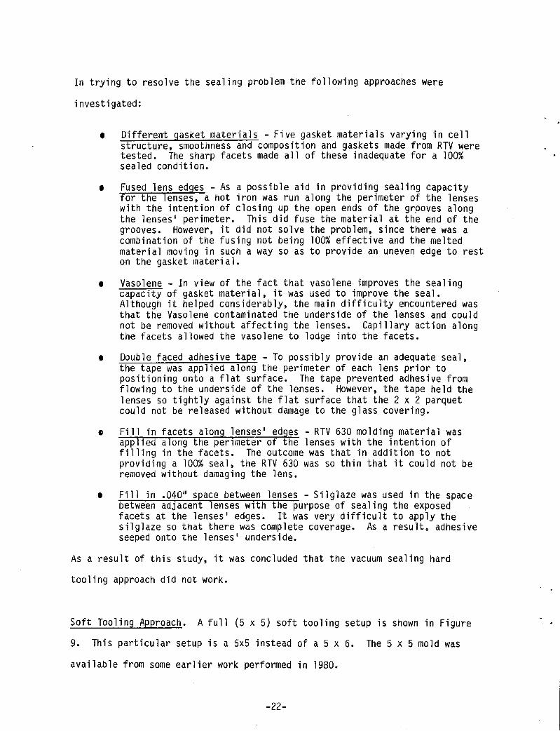
In trying to resolve the sealing problem the following approaches were
investigated:
• Different gasket materials - Five gasket materials varying in cell structure, smoothness and composition and gaskets made from RTV were tested. The sharp facets made all of these inadequate for a 100% sealed condition.
• Fused lens edges - As a possible aid in providing sealing capacity for the lenses, a hot iron was run along the perimeter of the lenses with the intention of closing up the open ends of the grpoves along the lenses' perimeter. This did fuse the material at the end of the grooves. However, it did not solve the problem, since there was a combination of the fusing not being 100% effective and the melted material moving in such a way so as to provide an uneven edge to rest on the gasket material.
• Vasolene - In view of the fact that vasolene improves the sealing capacity of gasket material, it was used to improve the seal. Although it helped considerably, the main difficulty encountered was that the Vasolene contaminated the underside of the lenses and could not be removed without affecting the lenses. Capillary action along the facets allowed the vasolene to lodge into the facets.
• Double faced adhesive tape - To possibly provide an adequate seal, the tape was applied along the perimeter of each lens prior to positioning onto a flat surface. The tape prevented adhesive from flowing to the underside of the lenses. However, the tape held the lenses so tightly against the flat surface that the 2 x 2 parquet could not be released without damage to the glass covering.
~ Fill in facets along lenses' edges - RTV 630 molding material was applied along the perimeter of the lenses with the intention of filling in the facets. The outcome was that in addition to not providing a 100% seal, the RTV 630 was so thin that it could not be removed without damaging the lens.
• Fill in .040" space between lenses - Silglaze was used in the space between adJacent lenses with the purpose of sealing the exposed facets at the lenses' edges. It was very difficult to apply the silglaze so that there was complete coverage. As a result, adhesive seeped onto the lenses' underside.
As a result of this study, it was concluded that the vacuum sealing hard
tooling approach did not work.
Soft Tooling Approach. A full (5 x 5) soft tooling setup is shown in Figure
9. This particular setup is a 5x5 instead of a 5 x 6. The 5 x 5 mold was
available from some earlier work performed in 1980.
-22-
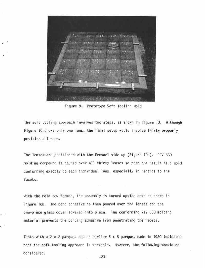
Figure 9. Prototype Soft Tooling Mold
The soft tooling approach involves two steps, as shown in Figure 10. Although
Figure 10 shows only one lens, the final setup would involve thirty properly
positioned lenses.
The lenses are positioned with the Fresnel side up (Figure lOa). RTV 630
molding compound is poured over all thirty lenses so that the result is a mold
conforming exactly to each individual lens, especially in regards to the
facets.
With the mold now formed, the assembly is turned upside down as shown in
Figure lOb. The bond adhesive is then poured over the lenses and the
one-piece glass cover lowered into place. The conforming RTV 630 molding
material prevents the bonding adhesive from penetrating the facets.
Tests with a 2 x 2 parquet and an earlier 5 x 5 parquet made in 1980 indicated
that the soft tooling approach is workable. However, the following should be
considered. -23-

Figure lOa
PRIMER (SS4179)
GLASS COVERPLATE __ --f-',I ~~ / 7 .
---rn~~~~~~~~~~~~~~~~~~~~~~~~~~~=== BOND ADHESIVE / ... ,' (534-044)
itI---- FRESNEL LENS RTV 630 ---ilH;:;: (ACRYLIC)
Figure 10. Soft Tooling Approach
Advantage of Soft Tooling
• RTV-630 will provide a complete seal around grooves and sides of lens so that adhesive will not contaminate the Fresnel side of the lenses.
Disadvantages of Soft Tooling
• RTV 630 mold requires 13 lbs. At $12/1b. this amounts to $156.00 for each parquet because the mold cannot be reused.
• Excessive time consumed to set up for making mold as well as positioning lenses and glass sheet.
• A total 18 hour cure time for both the RTV 630 and 534-004 makes it a slow process.
• Each lens must be held flat with double adhesive tape which will make removal difficult as well as possibly contaminate the lenses with adhesive.
-24-

Hard Tooling Approach - Without Vacuum (Baseline Process). The final approach
investigated, and the baseline lamination approach finally selected, was a
modified hard tooling approach that used a clear polyester/acrylic adhesive
tape to seal the individual lenses. The key features of this approach are
shown in Figure 11.
I MOLDED-IN SPACER FEET
TA PE _
Fi gure 11.
TAPE
• . ~ L~ .~ .~ 1 .~ .~~ ~ IL......... •
I I I METAL PINS FIXTURE
Key Features of the Baseline Lamination Approach
CLA SS RT V
LENSES
A flat aluminum plate has thirty .062 inch holes drilled in a 6x5 matrix with
hole center-to-center spacing of 6.700 + .001 inch. Metal dowel pins are then
inserted into each .062 inch hole. The drawing for this fixture is provided
in Appendix D. A photograph of the actual program fixture is provided in
Figure 12.
Figure 12. Full Size Parquet Lamination Fixture
-25-

Each lens has a corresponding hole molded into its center which mates to the
fixture's metal pin. Using this approach, very accurate lens-to-lens center
spacing is achieved, as shown in Figure 13.
+ 6. 700!!f-6. 699 + 6.700+6.700 + 6. 69s-t.-+-+--LENS CENTER ?" !" ~ ~ !" ~ TYP. 0'\ Q"l 0"1 0"1 O"l 0"1 \D t.O \.0 ("C Y' c.o t.O _ I.D 1..0 c.D (,Q t.O
1;; 6. 699t6. 700 f 6. 700i;;6. 700 t 6. 6991,:; . . . . . . 0'\ ....., ....., 0'\ ....... 0'\
::g g g ~ g ~
+ 6. 69s-t 6.700 + 6.700+ 6.699 + 6. 704 cr. O"l '" 0'\ 0"1 0'\
0'\ C"I C1'I 0'\ O"l 0"1 (.0 c.o \D Y) ("C \0 1.0 tD t.O ....... c.o \D 1. 6. 70D-t, 6.700 i 6. 700i;; 6.699 t 6. 699i:; . . . . . . ""-J O"l 0"1 0"1 0"1 en o t.O 1.0 (,0 c.o CD o t..C 00 \D c.D t.O + 6.698+ 6.699+ 6. 69!l.j- 6. 699 + 6.700+
Figure 13. Actual Lens Center-to-Lens Center Spacing
Small spacer feet are also molded into the planar surface of the individual
Fresnel lenses. These spacer feet serve to control the bond adhesive
thickness. A thin .002 inch 0.125 inch wide UV stabilized polyester tape with
an acrylic adhesive backing is then applied over the 0.050 inch gap between
each lens and around the parquet perimeter. The acrylic surfaces are then
cleaned and primed with GE RTV primer #554179. The bond adhesive RTV 534-044
is blended, deaerated and poured over the surface of the lens parquet
pattern. The glass is then immediately lowered onto the RTV starting from one
edge of the fixture and working to the other edge. Weights are then
positioned onto the glass, and the entire assembly is allowed to cure for at
1 east 4 hours.
-26-

. .
. .
The perimeter tape is then cut just under the facetted side of the lenses and
the entire 6x5 parquet lifted off the machined aluminum fixture. Excess tape
and RTV are then cleaned off the glass along the perimeter which completes the
parquet assembly.
Prototype Parquet Hardware. As part of the program twenty full size 6x5
parquet lens assemblies were assembled uSing the baseline lalnination process.
The drawing package for the parquet assembly is provided in Appendix C. Ten
parquets were assembled using 3mm thick Schott B270 glass and ten using 3mm
(.118 inch) thick Solakleer glass. Ten of the parquets were assembled using
compression molded Fresnel lenses with molded-in spacer feet and center
locating indent per GE drawing 47C258398 (see Appendix B). Ten of the
parquets were assembled using a sample of the latest injection molded lenses.
The injection molded lenses did not have the molded-in center indent or spacer
feet. The decision to go to these molded-in lens features was made after the
injection mold fabrication task had started. The twenty parquets were
delivered to Sandia for subsequent evaluation and testing.
Lamination Transmission Evaluations. The spectral transmittance and optical
performance of the glass-RTV-acrylic lens lamination were evaluated.
The spectral transmittance was measured at Sandia under the direction of David
King. The transmittance results are shown in Figure 14.
For comparison, the transmittance characteristics of 0.148 inch thick
plexiglass is as provided. From this data, the transmittance for the laminate
and plexiglas specimens was calculated to be .8895 and .9176 respectively over
a .25 to 1.09 AMl.5 solar spectrum range.
-27-

LENS SPECTRAL TRANSMITTANCE 9 ~~--~---r--~~~--;-~---r---r--~--r-~--~---r--~ !.. : !
~: =-fICCl"~:.r\ i=-E:1~-1~f~1;i,1]=-~ Q) i:! i i ! i : ! \ n • i:""'- 0.210 INCH THICK
~; ::::::::J::::',:1 ::1.::::::::::,1::::::,::::1::'::::':::1.::::::'::,,1':::::::",I~::::::':::I: ;'::::tl":"':,::':l,":\'::::I:::::::::::r~:~~f.~~l~:::', t :! [0.148 INCH THICK ACRYLIC i ~: i ~ i i ! i
.", 00 0 .... ~~ , ~O ::r: U~ ~ p.. ... 00 0
~ ~~~~--~--~--~--~~--~--~--~--~~.~.~~--~--~ 0.0 0.2 0.4 0.6 0.8 1.0 1.2 1.4 1.6 1.8 2.0 2.2 2.4 2.6 2.8 3.0
WAVELENGTH (p,m)
Figure 14. Laminate Spectral Transmission
The effective optical performance of the laminate was determined via outdoor
testing at GE using an Applied Solar Energy Corporation 2.35 x 2.35 cm silicon
concentrator cell. Individual 7 inch square glass-RTV-compression molded GE
Lens IV-c lens laminates were prepared using both Schott 8270 and Solakleer
glass superstrates. The results of this testing are provided in Figure 15.
The plotted data represents averages of over 38 individual lens-cell test
runs. As shown, data points are provided comparing Schott, Solakleer and
varying degrees of cleanliness. The plastic lens only is a thin 0.070 inch
compression molded control.
The module efficiency is the resulting single lens laminate-cell efficiency
adjusted to a 280 C cell temperature. Assuming a 18.5% cell efficiency at
280 C and 70X concentration, the effective lens laminate optical efficiency
-28-
. .

w
" :::> ... « " w Q. :; W ... -l -l W U
i;' " N
" ,.. U Z w 14. U u: "-w W -l :::> C 0 :;
~ 6", ""'0
0- SOLAKLEER-llclean'~ 0-· SCHOTT-lIel.an ti
0- SCHOTT-lldirtyll
6 - PLASTIC LENS ONLY 0- SOLAKLEER-lldirtytl
--------~ 1""-I "'" I
I ~'" o
I '" I "'" --______ 1 _____ . ____ ~
1000
DIRECT NORMAL INSOLATION-w/m 2
Figure 15. Laminated Lens-Cell Efficiency Data
is approximately 82.7%. Of interest is the relatively insignificent impact of
"clean" versus "dirty" lenses and Schott versus Solakleer. The "dirty" lenses
were not excessively dirty, but did have random finger prints on the glass and
small RTV chips in some of the facets. We wanted to evaluate how critical it
was to keep the lens-laminate "clean."
-29-

Section 5
Bond Integrity Studies
Summary. Throughout the lamination process development effort,
glass-adhesive-plastic laminate specimens have been periodically subjected to
temperature and humidity cycling. Various degrees of delamination have been
found. As stated in the summary of this report, this has been a ,frustrating
problem in that, technically, the material "experts" at GE-Silicone Products
Department felt that our material system of glass-RTV 534-044 and primed
acrylic should not delaminate under the thermal-humidity conditions in
question.
In an attempt to identify the cause and a suitable fix, GE has analyzed the
potential relative humidity environment, surveyed existing temperature and
humidity cycling procedures, and conducted an in-house delamination-process
study.
Relative Humidity Environmental Analysis. A survey of current relative
humidity test requirements for other solar hardware development programs has
shown a wide range of relative humidity/temperature specifications. For
example, JPL specifies an 85% r.h. at 300 C test condition for its ll-meter
dish collector program and an 85% r.h. at 850C for its Block V flat plate PV
module test.
In order to define the test requirements for the laminated Fresnel lens
parquet, a survey of the relative humidity and temperature combination
profiles was made for locations along the Atlantic Coast and the Gulf of
Mexico. Based on the TMY weather data, Miami and Fort Worth have the worst
-30-

. .
. .
temperature/relative humidity combinations and these profiles are presented in
MIAMI
------ FORT WORTH 500
(D&N) - DAY AND NIGHT
w ~ 400 w
(D) DAYTIME ONLY
<>: <>: ::;)
u u o LL 300 o <II <>: ::;)
o :I:
::; 200
o z
100
20 30 40 50 60 70
% RELATIVE HUMITIDY
Figure 16. Ambient Temperature-Relative Humidity Occurrence Profile
It can be seen that the high humidity (75% at 25-30oC hours in Miami) occur
mostly during the night. As the ambient temperature increases during the day
(30-350 C), the relative humidity decreases significantly due to the increase
in water-vapor capacity of the air with increasing temperature.
If the point-focus Fresnel module design, which uses a laminated parquet,
incorporates a breather/filter, the worst environmental humidity-temperature
combinations the parquet will see are those shown in Figure 16. As the module
becomes operational during the day, the air inside the module housing is
-31-

heated and will leave the module housing in order to maintain equal pressure
with the ambient. Assuming that no water vapor escapes through the breather
filter, the relative humidity as a function of increasing inside air
temperature will follow the constant water vapor 1 ines on the psychrometric
chart shown in Figure 17.
% RELATIVE HUMIDITY COl 0 01 01 coo 1J:I.::t N
1000 cr: <
tZ' >-0 cr: '- 0
$ 130 800 0 z
J:i :> 0
f... a. ~ cr:
4.0 600 w
a.
i cr: Q 0 a.
~ < >
~ 400 cr: IiJ w
:::," f-IiJ <
,.:, 3:
~ OJ)
200 :=: < cr: <J
60 100 140 180 220 260 300
DRY-BULB TEMPERATURE (OF)
Figure 17. Psychometric Chart for Air at Barometric Pressure 29.92 In. Hq.
The mechanism for parquet delamination is probably the absorption of moisture
by the acrylic lens which results in swelling and consequently pulling away
from the adhesive. The major force behind the moisture migration and
penetration is constituted by the vapor pressure imposed on the lens. Current
accelerated environmental tests subject the laminate to vapor
pressures/relative humidities-temperature combinations that are higher than
-32-
. .

. ,
. -
those that might ever be experienced.
Temperature-Humidity Cycling Procedures. In an attempt to identify how the
glass and plastic industry evaluates bond integrity versus temperature and
humidity cycling, a review of ASTM Standards and contacts to various industry
sources were made.
An extensive review of the ASTM Standards identified the following documents
as having possible relevance to the problem:
1. ASTIVJ 0 618:
2. ASTM 0 759:
3. AS TM 0 3045:
4. ASTM 0 1151:
Conditioning Plastics and Electrical Insulating Materials for Testing
Conducting Physical Property Tests on Plastics at Subnormal and Supernormal Temperatures
Heat Aging of Plastics Without Load
Effect of Moisture and Temperature on Adhesive Bonds
Items 1. through 4. were carefully examined with particular emphasis on 4.
However, this documnent was applicable only to adhesive bonds subjected to
continuous exposure. Furthermore, Note 1 in the document states, "The
condition under which the exposed specimens are tested will depend upon the
nature of the adhesive, the adherence, and the strength property being
investigated. This will be prescribed by the material specifications or by
written agreement between the manufacturer and purchaser of the adhesive."
Following the review of the available ASME literature, the Staff Manager (Jane
Turner) of ASTM Committee E44 (Solar Energy Conversion) was contacted at ASTN
Headquarters in Philadelphia. Ms. Turner also reviewed the literature,
-33-

including most recent proposed changes, and could find nothing applicable to
temperature/humidity cycling.
At Ms. Turner's suggestion, Dr. Howard Swift, Libby-Owens-Ford Glass Company,
and a long-time member of ASTM Committee C14.08 (Flat Glass) was contacted.
Dr. Swift was sympathetic and stated that the glass industry recognizes the
problem since the use of silicone bonded flat glass is increasing. However,
ASTM Committee C14.08 has not specifically addressed the problem.
Mr. David Nerrow of GE-Silicon Products Department made the following comments:
1. Any temperature excursion causes large expansion/contraction in
adhesive and therefore requires careful thermal analysis of entire
system.
2. RTV Adhesive 534-044 is an excellent choice.
3. The loss of adhesion in on"Jy small areas suggests that bonding
system and technique are good, but perhaps cleaning methods,
primer and bond application techniques should be more carefully
controlled.
A contact with Rohm and Haas resulted in obtaining a copy of a brochure,
"Thermal and Humidity Differential Bonding - PL72f," whic(J states that changes
in humidity and temperature may produce slight dimensional changes. However,
these changes are not instantaneous, but require several days for equilibrium
-34-

. .
to occur. Therefore climatic changes are rarely stable long enough for
Plexiglas (acrylic) to equilibrate at a given humidity.
As a result of our survey, we concluded that no standard temperature/humidity
cycling test exists for evaluating the subject parquet bond. Further work is
needed to formulate appropriate temperature/humidity cycling test
specifications for a laminated Fresnel parquet.
Delamination Studies. During an October 1981 review with Sandia, the results
of a Sandia conducted thermal/humidity cycling test were discussed. A summary
of the findings was that random bubbles ranging from 1/16 inch to 3/8 inch in
diameter and delamination lines particularly around the spacer tabs/feet was
observed in all five test specimens.
The bubble development was felt to be due to very small, visually undectable,
pockets of entrapped air in the 534-044 blend that were incompletely removed
in the deaerating operation. With the exposure to elevated temperature these
pockets then expanded into the visible, various-sized bubbles. The
delaminations were felt to be due to inadequate primer application. For the
RTV adhesive system to work with acrylic a thin, uniform primer coat is
essential. All delaminations seem to start at the acrylic interface. Several
of the test specimens that were peeled apart clearly show that portions of the
acrylic lens surface never had any primer.
In an attempt to resolve the delamination problem, GE conducted an in-house
delamination study. A listing of the various process conditions evaluateq is
provided in Table 8.
-35-
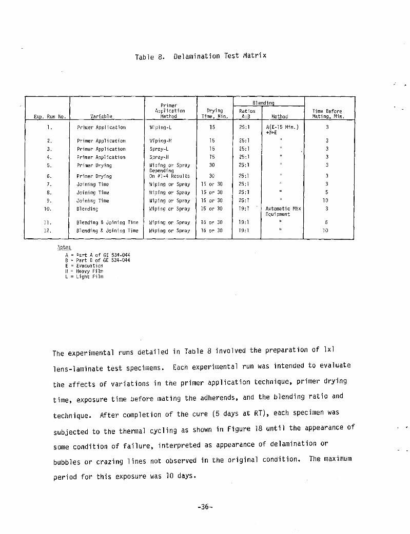
Table 8. Delamination Test IVJatrix
Primer Blending Application Drying Ratios Time Before
EXD. Run No. Variable Method Time, Min. A:B Method Mating, Min.
l.
2. 3.
4. 5.
6.
7. 8.
9.
10.
11. 12.
Primer Application
Primer Application Primer Application Primer Application Primer Drying
Primer Drying Joining Time
Joining Time Joining Time Blending
Blending & Joining Time Blending & Joining Time
Notes A = Part A of GE 534-044 B = Part B of GE 534-044 E = Evacuation H = Heavy Film L = Light Film
Wiping-L 15
fliping-H 15 Spray-L 15 Spray-H 15 Iii ping or Spray 30 Depending On #1-4 Results 3D Hiping or Spray 15 or 30 i'liping or Spray 15 or 30 Iii pi ng or Spray 15 or 30 Wiping or Spray 15 or 30
Wiping or Spray 15 or 30 liiping or Spray 15 or 30
25:1 A(E-15 Min.) 3 +B+E
25:1 " 3
25: 1 " 3
25: 1 " 3
25: 1 " 3
25: 1 " 3 25: 1 " 3 25: 1 " 5 25: 1 " 10 19: 1 Automatic Mix 3
Equipment 19: 1 " 5 19: 1 " 10
The experimental runs detailed in Table 8 involved the preparation of lxl
lens-laminate test specimens. Each experimental run was intended to evaluate
the affects of variations in the primer application technique, primer drying
time, exposure time before mating the adherends, and the blending ratio and
technique. After completion of the cure (5 days at RT), each specimen was
subjected to the thermal cycling as shown in Figure 18 until the appearance of
some condition of failure, interpreted as appearance of delamination or
bubbles or crazing lines not observed in the original condition. The maximum
period for this exposure was 10 days.
-36-
. .

. -
160 1509F
lQO
120 ~ 0 100
w 80 7~ ~ ~ ~ 60 ~ ~ w QO ~ ~ w 20 ~
0
-20
-QO 0 Q 8
HOURS
Figure 18. Daily Thermal Cycle for Delamination Study
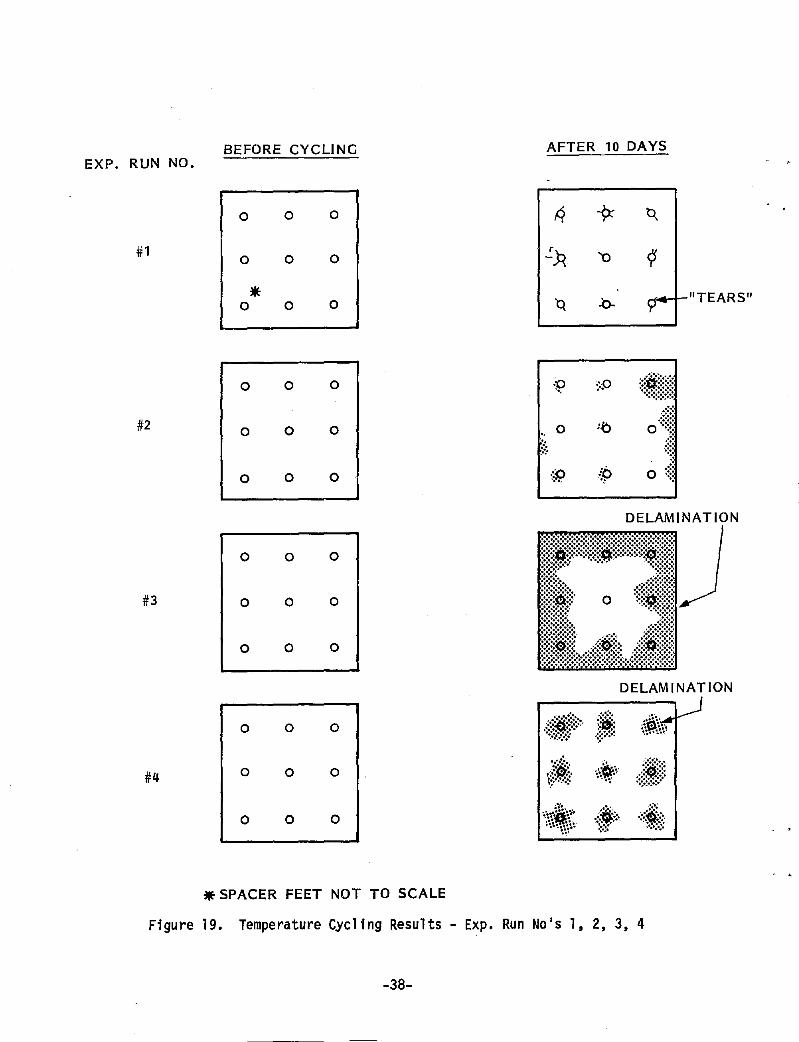
Results for experimental (Exp.) run numbers 1 through 6 and g and 10 are
presented in Figures 19 through 21. A review of these results produced the
following conclusions:
1. Primer application is critical. A wiped, heavy film works the best.
2. The delaminations or tears show up after the first day of cycling.
3. The delaminations seemed to always start at the spacer feet locations.
4. The test specimen without spacer feet did not exhibit any delaminations after four days of cycling. Apparently the spacer feet contribute to an excessive stress build-up in the RTV adhesive bond.
Full Size Parquet Delamination. Several full size 6x5 parquets were assembled
and placed outdoors. After a three month exposure minor delaminations were
observed. Figure 22 shows the locations and frequency of these delaminations
-37-
BEFORE CYCLING AFTER 10 DAYS EXP. RUN NO.
0 0 0 R -9: ~
#1 0 0 0 ':.3i '0 <:s
* "TEARS" 0 0 0 -b- rr
0 0 0 .p ",
::p ::~i~@~1 #2 0 0 0 0 '0 O·:~t
" '. ..•. ; ..... .::~~
0 0 0 {f;' ~9 0 ~::~
DELAMINATION
0 0 0
#3 0 0 0
0 0 0
DELAMINATION
0 0 0 ·:tAf::· .!~: ,\-&\~~ '.~.'':.~~~'
#4 0 0 0 .;::i:. t;:···.·:::
..~;. ':.~-.':., .. .J~~~:~
::~:;:!::: ••
0 0 0 .... ~~. j .. :::.1& ~~\~~\~ ... ~::: .... :'"
','.' .
• SPACER FEET NOT TO SCALE
Figure 19. Temperature Cycling Results - EXp. Run No's 1, 2, 3, 4
-38-

EXP. RUN NO.
#5 MOLDED-IN
SPACER FEET
#6 MOLDED-IN
SPACER FEET
BEFORE CYCLING
0 0 0
0 0 0
0* 0 0
o o o
o o o
o o o
AFTER 5 DAYS
p 0
9 0 . 0
~ 0
o
o Q o
o
NO GROSS DELAMINATION. TEARS ARE SLIGHT!.,. Y LESS WITH #6. NONE ARE LARGER THAN 1/16 INCH.
* SPACER FEET NOT TO SCALE
Figure 20. Temperature Cycling Results - Exp. Run No's 5, 6
-39-

V)
>« a 0:: U
J lLl. « -Ll. 0 0 III
0 l-Ll. 0 0 N
I
>-« a 0:: U
J I-Ll. « U
Z
..I U
>-U
UJ
0:: 0 Ll. U
J I:!l . 0 Z
Z
:::J 0:: . 0.. X
U
J
:j~" 0
0 0
0
f/:.
lk#!;;; fi1i
0 0
0 0
0
0 0 CI>
""
o o
;iH'lit.~~{,
0 0
0
UJ
;'··:{~ft·· ..I « u V
)
0 l-I-0 z I-UJ
UJ
Ll. 0
0:: U
J U
0 0
0 « 0.. V
)
* *
0
I-Z
U
J U
J I
UJ
U
a Ll.
« I-U
JUJ
0 0..
UJ
.... V
) UJ
au
""
Ll. ..1«
0 0
0..
Z
::2: V
)
Figure 21. T
emperature
Cycle
Results
-EXp.
Run N
o's 9,
10
-40-

RTV FLOW
0 0 0 0 0 0 0 0 0 0 0 0 0 0 0 0 o :;Iil!: 0 0 0 0 0 0 0 0 0 0 0 0 0 0 0 0 0 ii;(
0 0 0 0 0 0 0 0 0 0 0 0 0 0 0 0 0 ~;
0 0 0 0 0 0 0 0 0 0 0 0 0 0 0 0 0 0
0 0 0 0 0 0 0 0 0 0 0 0 0 0 0 0 0 0
::9:: 0 0 0 0 0 0 0 0 0 0 0 0 0 0 0 o ..is: :.
0 0 0 0 0 0 0 0 0 0 0 0 0 0 0 0 0 0
0 0 0 0 0 0 0 0 0 0 0 0 0 0 0 0 0 0
:§} 0 0 0 0 0 0 0 0 0 0 0 0 0 0 0 0 t;!; ..
#1 0 0 0 0 0 0 0 0 0 0 0 0 0 0 0 0 0 0
0 0 0 0 0 0 0 0 0 0 0 0 0 0 0 0 0 0
:::jt o' 0 0 <:> 0 0 0 0 0 6 0 0 0 0 0 0 9j.
0 0 0 0 0 0 0 0 0 0 0 0 0 0 0 0 0 :.g', 0 0 0 0 0 0 0 0 0 0 0 0 0 0 0 0 0 0
:~p:.' O·}l~. 0 0 0 0 o \\~\\ 0 o :\P.: 0 o '\'f~-;,: :}i! 0 :i:i.
RTV FLOW t
0*0 0 0 0 0 0 0 0 0 0 0 0 0 0 0 0 6: o 0 0 0 0 0 0 0 0 0 0 0 0 0 0 0 0 cf..
:0 0 0 0 0 0 0 0 0 0 0 0 0 0 0 0 0 6:: '.'
0 0 0 0 0 0 0 0 0 0 0 0 0 0 0 0 0 0: 0 0 0 0 0 0 0 0 0 0 0 0 0 <:> 0 0 0 0
.. :0 0 0 0 0 0 0 0 0 0 0 0 0 0 0 0 0 .p:. ....
#2 Q: 0 0 0 0 0 0 0 0 0 0 0 0 0 0 0 0 0
0 0 0 0 0 0 0 0 0 0 0 0 0 0 0 0 0 0
.p. 0 0 0 0 0 0 0 0 0 0 0 0 0 0 0 0 0
"<;I: 0 0 0 0 0 0 0 0 0 0 0 0 0 0 0 0 0
0 0 0 0 0 0 0 0 0 0 0 0 0 0 0 0 0 0
0 0 0 0 0 0 0 0 0 0 0 0 0 0 0 0 0 ~:
0 0 0 0 0 0 0 0 0 0 0 0 0 0 0 0 0 0
0 0 0 0 0 0 0 0 0 0 0 0 0 0 0 0 0 0
':p 0 0 .p'" .t!. :0' .. ': .......... 0 0 .?::. 0 0 ~. 0 0 ·9::' 0 0 .~:.
* SPACER FEET NOT TO SCALE
Figure 22. Representative Full Size Parquet Delaminations
~4l~

for two representative parquets. From a study of these Figures the following
conclusions were reached:
1. The total delamination area represents only .09% of each parquet's total area.
2. The delaminations are always located at the spacer feet and only along the outer parquet edge.
3. The specific location and frequency of the delaminations varies from parquet to parquet.
4. The parquet edge where the RTV was first poured has a significantly lower occurrence of delamination than the opposite edge.
In summary, we have experienced minor delamination at some of the outer edge
spacer feet locations. The total area involved is very minor. The question
of whether or not the delamination will progress to a point where serious lens
performance degradation exists is still open. Extended outdoor exposure is
needed to answer this question adequately.
-42-
Section 6
Injection Molding Lens Development
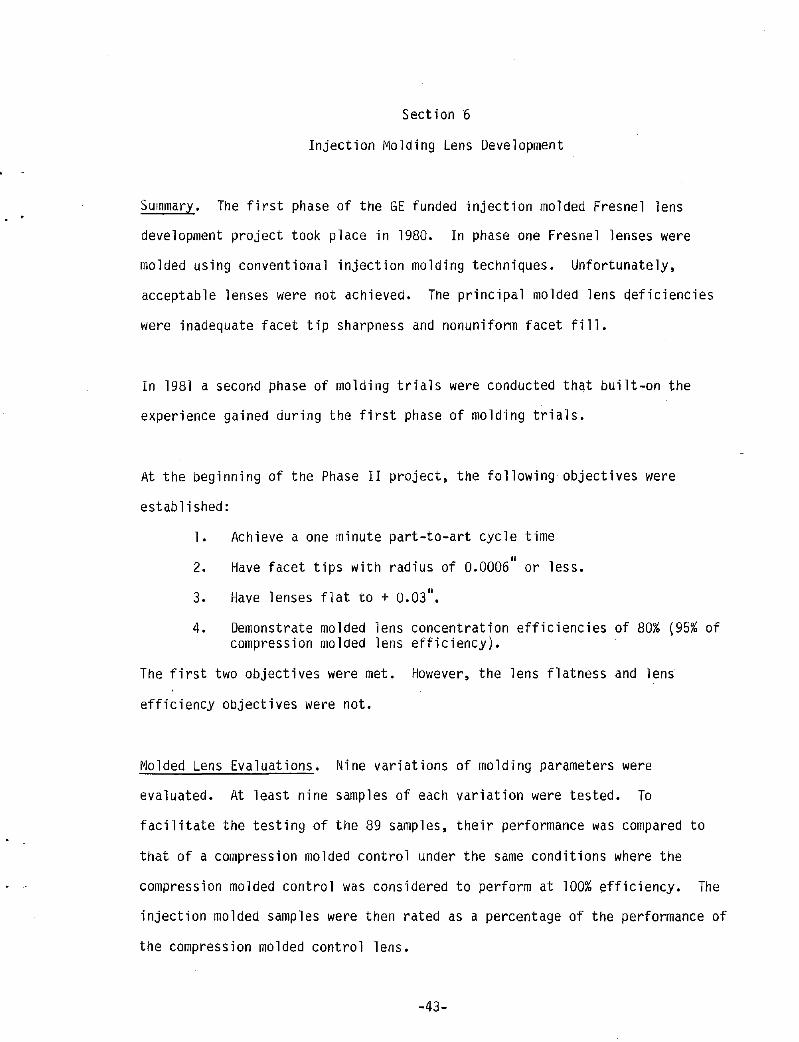
Summary. The first phase of the GE funded injection molded Fresnel lens
development project took place in 1980. In phase one Fresnel lenses were
molded using conventional injection molding techniques. Unfortunately,
acceptable lenses were not achieved. The principal molded lens deficiencies
were inadequate facet tip sharpness and nonuniform facet fill.
In 1981 a second phase of molding trials were conducted th&t built-on the
experience gained during the first phase of molding trials.
At the beginning of the Phase II project, the following objectives were
established:
1. Ach i eve a one mi nute part-to-art cyc 1 e time 01
2. Have facet tips with radius of 0.0006 or less.
3. Have lenses flat to + 0.03".
4. Demonstrate molded lens concentration efficiencies of 80% (95% of compression molded lens efficiency).
The first two objectives were met. However, the lens flatness and lens
efficiency objectives were not.
Molded Lens Evaluations. Nine variations of molding parameters were
evaluated. At least nine samples of each variation were tested. To
facilitate the testing of the 89 samples, their performance was compared to
that of a compression molded control under the same conditions where the
compression molded control was considered to perform at 100% efficiency. The
injection molded samples were then rated as a percentage of the performance of
the compression molded control lens.
-43-

The lens test set-up is shown in Figure 23. A fixed target distance of 7.875
inches was used with a limiting aperture of .61 inch square, masking a .8 inch
square photovoltaic cell. Voltage was read across a 1.5 ohm resistor placed
in parallel with the cell. Light concentration was virtually proportional to
voltage.
SUN SIMULATION
FLASHED OPAL GLASS DIFFUSER WITH 0.25" APERATURE
[FOR 0.5° SOURCE)
PROJECTION LAMP TYPE EJN 150W 21V
0-60 VOLT 0-8 AMP
" j.
~
.,
SYSTRON DONNER VOLTAGE AND/OR CURRENT REGULATED POWER SUPPLY
29t1
SCATTERED LIGHT SHIELD [OPAQUE BLACK)
Figure 23.
SOLAR CONCENTRATOR LENS [TEST LENS)
~-----------~6 FT------------~·I
COLLIMATING FRESNEL LENS 29:00 CONJUGATES [21-718" X 28-3/4")
Injection Molded Lens Test Set-up
SECONDARY CONCENTRATOR
TARGET DIODE
TEST ISTANCr:----H
DMM [IA AMPS)
The solar angle of .50 was simulated with a large Fresnel lens and
appropriate light source. No compensation was made for nonuniformity of
illumination by the Fresnel collimator, due to the small central portion of
the Fresne 1 utili zed and because the same pos it ion in the co 11 imat i on beam was
used for all test samples. Since comparative data was sought, duplication of
-44-
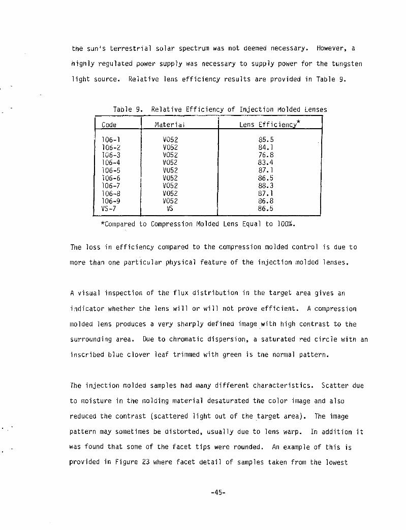
the sun's terrestrial solar spectrum was not deemed necessary. However, a
highly regulated power supply was necessary to supply power for the tungsten
light source. Relative lens efficiency results are provided in Table 9.
Table 9. Relative Efficiency of Injection Molded Lenses .---
Code Material Lens Efficiency* I
106-1 V052 85.5 106-2 V052 84.1 106-3 V052 76.8 106-4 V052 83.4 106-5 VU52 87.1 106-6 VU52 86.5 106-7 V052 88.3 106-8 V052 87.1 106-9 V052 86.8 VS-7 VS 86.5
*Compared to Compression Molded Lens Equal to 100%.
The loss in efficiency compared to the compression molded control is due to
more than one particular physical feature of the injection molded lenses.
A visual inspection of the flux distribution in the target area gives an
indicator whether the lens will or will not prove efficient. A compression
molded lens produces a very sharply defined image with high contrast to the
surrounding area. Due to chromatic dispersion, a saturated red circle with an
inscribed blue clover leaf trimmed with green is the normal pattern.
The injection molded samples had many different characteristics. Scatter due
to moisture in the molding material desaturated the color image and also
reduced the contrast (scattered light out of the target area). The image
pattern may sometimes be distorted, usually due to lens warp. In addition it
was found that some of the facet tips were rounded. An example of this is
provided in Figure 23 where facet detail of samples taken from the lowest
-45-

· . . - .. ..i-*
Group I
Group n
Figure 23 Processing Conditions Impacted Facet Sharpness
-46-

. .
efficiency group (group I) and highest efficiency group (Group II) are shown.
In some cases, the image looked quite acceptable, compared to a compression
molded sample, but when tested could be found to have efficiencies on the low
side. The reverse is also evident at times with poorer appearing images
giving higher efficiencies than normally would have been predicted.
Outdoor Lens Testing. Samples from the various molding runs were tested
outdoors at GE. A summary of the test results is provided in Table 10. As
shown, calculated injection molded lens efficiencies varied from 68 to 75%.
Our goal of an 80% efficient lens was not aChieved; however, significant
improvement from 1980 to 1981 was demonstrated.
Table 10. Summary of Injection Molded Lens Outdoor Testing
Normalized Calculated GE Molded Lens Lens Group Lens-Cell Efficiency Lens Efficiency 1 Vs Control Lens
VS-Run 7 .133 .72 .867 Run 7-1 • 124 .68 .819 Run 7-8 .126 .68 .819 VS -Run 7 .132 .72 .867 Run 3 .126 .68 .819 Run 7-5 • 125 .68 .819 End of Year .138 .75 .904 Run '81
1980 Run .11 0 .60 .723 Compression I~o 1 ded • 152 .83 1.00 Lens (Contro 1)
1. Normalized lens-cell efficiency assumed cell efficiency (.184).
-47-
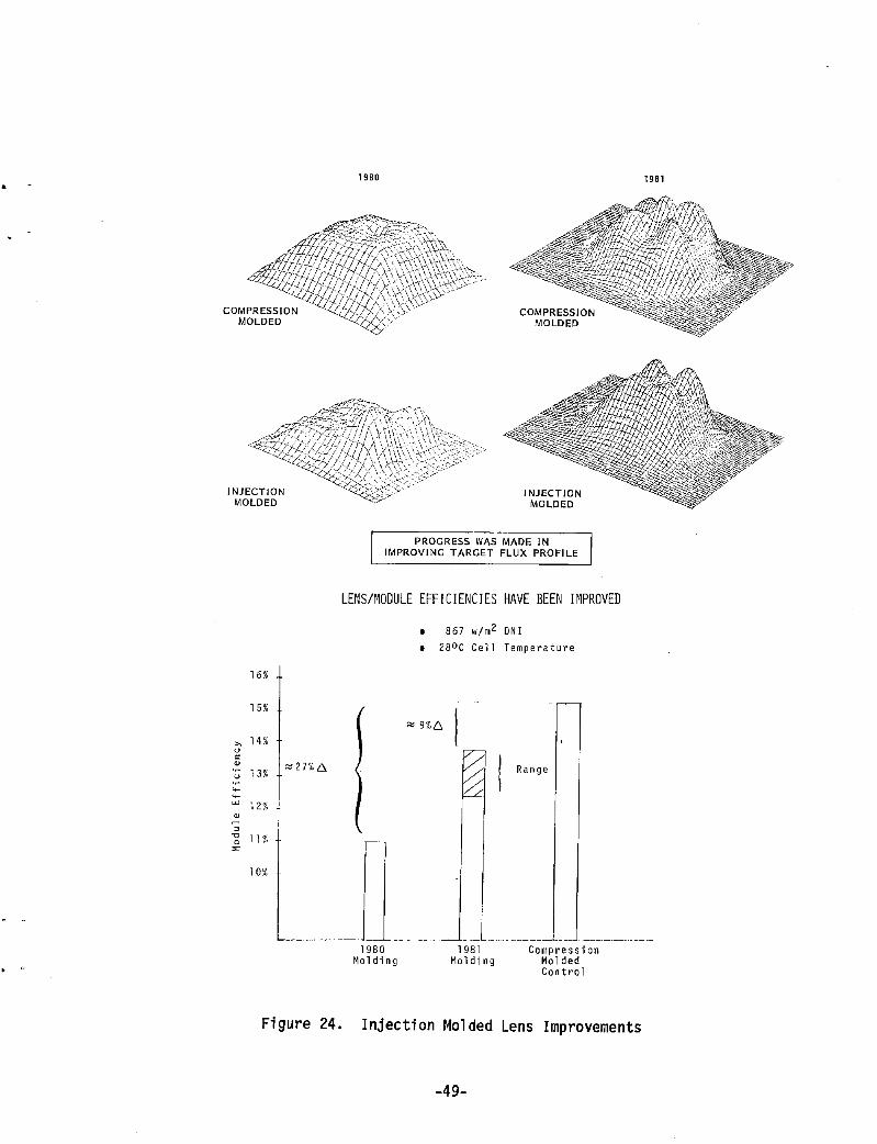
Phase I vs. Phase II Results. A comparison between Phase I and Phase II
injection molded lenses is provided in Figure 24. As shown, a significant
improvement was achieved in improved focused flux uniformity. A respectable
improvement was also achieved in net module (lens-cell) efficiency.
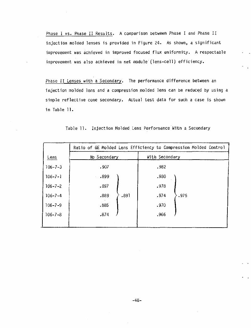
Phase II Lenses with a Secondary. The performance difference between an
injection molded lens and a compression molded lens can be reduc~d by using a
simple reflective cone secondary. Actual test data for such a case is shown
in Table 11.
Table 11. Injection Molded Lens Performance With a Secondary
Ratio of GE Molded Lens Efficiency to Compression Molded Control
Lens No Secondary With Secondary
106-7-3 .907 .982
106-7 -1 .899 .980
106-7-2 ~ .897 .978
i 106-7 -4 .889 .891 .974 .975 ,I
106-7-9 I .885 .970
106-7-8 .874 .966
-48-
INJECTION MOLDED
16%
15%
" 14%
u ~
'" u 13%
---- 12% ~ ~
"0 II % 0
'" 10%
",27%[}.
1980
INJECTION MOLDED
PROGRESS WAS MADE IN IMPROVING TARGET FLUX PROFILE
LENS/r10DULE EFFICIENCIES HAVE BEEN Ir1PROVED
/
(
I
1980 110lding
867 w/m 2 DN I
• 28 0 C Cell Temperature
I 981 Molding
Range
Compression Molded Control
Figure 24. Injection Molded Lens Improvements
-49-
1981

Key Results and Conclusions
Summary. The main objectives of the program were to:
1. Develop an improved pOint focus Fresnel lens
2. Develop a lamination process capable of assembling large parquet
laminated Fresnel lenses.
3. Continue the development of an acceptable injection molded point
focus Fresnel lens (GE funded effort)
Key Results. Key results regarding each of these objectives follows.
Improved Lens Design Development. Several design variations have been
developed. After close interaction with Sandia, two lens designs were
selected. Lens design II retains the initial lens design 0.015 inch facet
width, but with an improved focused flux profile and efficiency. Lens design
IVc has 0.030 inch facets and is slightly more efficient than design II.
Masters for both lens designs were cut and proof-of-design lenses were
compression molded. GE and Sandia outdoor testing indicate that the
transmission efficiency goal of 80io was achieved.
Lamination Process Development. A variety of lamination techniques were
investigated. After a series of prototype lamination trials, an approach was
selected that utilized molded-in lens features to help control lens centering
as well as adhesive thickness. A clear tape is used to keep the liquid RTV
adhesive out of the lens facets. Twenty prototype full size parquets were
assembled using the selected approach.
-50-

. .
Development of Injection Molded Point Focus Fresnel Lenses.
A state-of-the-art precision injection mold was designed and fabricated.
Using electro formed Fresnel inserts, over 1000 lenses were molded under a
variety of processing conditions. Resulting lens efficiencies varied with
each set of processing conditions. Unfortunately, our efficiency goal of 80%
was not achieved. However, significant improvements were made in facet tip
sharpness (filling) and focused flux profile uniformity.
Conclusions. The following summarizes our major program conclusions:
1. The selected liquid adhesive system is a labor intensive approach. Care must be exercised in mixing and dearating the adhesive's two component parts, priming the acrylic lenses and in controlling the adhesive thickness, especially around the perimeter of the lens parquet pattern. A reliable delamination free bond has not been demonstrated using the GE RTV 534-044 adhesive. This adhesive approach is currently unacceptable for this application. Removing the need for the spacer feet might help.
2. A laminated lens exhibits a negligible performance loss as compared to a solid acrylic lens.
3. Several attractive glass types are available.
4. Injection molding definitely offers the potential for significant individual lens price reductions e.g. from ~9 to ~.80 each for a 6.66 inch square x 0.070 inch thick lens. Its main drawback is its size limitation. Injection molding a full size 41.5 x 34.5 inch parquet requires a very large machine. The capital cost of the machine and mold are significantly higher than for a compression molded full size parquet.
5. Product i on costs est imates for 6x5 1 ami nated parquet 1 ens opt ions are as follows:
Existing RTV Adhesive Potential Thin Film Approach Adhesive & Lens Approach
Labor ~ 107 .00 (5 hrs ea) 14.30 (40 min ea)
Adhesive 8.50 (2.40 lbs ea .92 (1.16 lbs ea (9 $3.50/10) @ ~.80/1b.)
Lens 24.00 (~.80 ea) 11.70 (9.8 ft2 @ ~1.20/ft2)
Glass 8.70 8.70 ~148.20 $35.62
-51-

For these estimates production volumes of at least 10000 lenses per year are assumed. For comparative purposes the estimate cost of a solid acrylic 6x5 parquet lens is approximately $60 each.
6. The outstanding durability, cleanability and low cost potential make the quest for a viable glass-laminate lens worthwhile.
-52-

APPENDIX A
GE RTV 534-044 PROPERTY SHEET

~J
I v
J
I ,j
, < I J
. "/ ,j
-1 I
Table 3-3. Properties of GE Experimental Pottant 534-044
534-044 Experimental Photovoltaic Pottant
Product Description
GE 534-044, experimental photovoltaic pottant is a twrcarp:>nent, low viscosity, 1m." rrodulus, R1V silicone rubber. After the adciition of t..'1e curing aaent, 534-044 nay be cured at roan temperature or with mild h~t to a flexible nfuber. G:)(:d adhesion to many substrates is achieved without a prirr.er.
Typical Uncured properties
Color 534-044A 534-044B
Viscosity, cps
Clear, Colorless Clear, Pale Yellow 900 - 1500
T}'pical ClZed Prc?2rties (72 hrs. at 25°C and 5u~ R.n.)
mrk Time @ 25 °C, min. Tack Free @ 25°C, hrs. Cure Time @ 25°C, hrs.
Color Refractive Index Specific Gravity
Catalyst Level
Durorreter, Shore A Dielectric Strength, v/mil Dielectric Constant, 1 k Hz Dissipation Factor, 1 k Hz
5%
15 1 4
Clear, 1.4075 0.98 21 500 2.89 .002
4% 2%
30 60 1.25 2
4 6
Colorless
Any review, recommendation, or statemenl. made on behalf of Silicone Products Department of General Electric Company relating to any engineering deSign. "rcilltectural drawing, product formulation, end-use specification, or similar document is limited to the knowledge 01 product properties as determined by laboratory testing of material produced by Silicone Products Department, Any comments or suggestions relaling to any subject other than such product properties are offercd only to call to the altent:on 01 tile en(JII,eer. ",chltecl. lormulator, end-user, or other person, conSiderations which may be relevant in his independent (:villu"llOn and determination of Ihe appropriateness of such design, drawing, specilicalion, document or formul". Silicone Products DCPJrtnlent expressly disclaims any liability for any damage, harm, injury, cost or expense to any person re5l1l1l11q. clII"ctlv or ",directly, from that person's, or any other person's. reliance on any such review. recommendation. statement. comn1 cnt or suqgcsllon.
.
A-I

. -
APPENDIX B
PARQUET LENS DRAHINGS

b:l I /-'
'-. f()
•
I
I 4
\,XACJ& 5qll/'/.;'L C()fJ./.f.·~ (7'h J ,,-)
" r
/I
34 J;,z
I !
i I
...t
1- 3./1 41%6
r-
Pi SUFFIX
5 I 4
I ~~ 3 I
{-DUBBED C0lj;£k~ (TYPIUIL 4 L5)
l .134 --.115 (31.11.1)
1 -1
® UNLESS OTHERWISE SPECIFIED OIMENSIONS "RE IN INCHES. TOLER"NCES ON:
FRAT,IONS OECIM"LS MIQLES
:!:Yj6:!:-±
All SURFACES '"';./
MATl·
47[)2'78399 APFC 5E:.E:. No'c-5 NEXT ASSY USED ON
APPLICATION
1 ~t ~ 3 I
2 I'm 478258 4-4'2 j'"OF 1 I""' REVISIONS
ZONE lTR DESCRIPTION DATE APPROVED
1 1 I I
0
NOTES: f-1. DRAWING TERMS & TOl. PER ANSI-Y14.S.
2. EDGES WILL 3E TREATED so THAT YOU HAVE A CONDITION FOR SAFE HANDLING.
3. THE MATERIAL SHALL BE ANNEALED, CLEAR GLASS HAVING A TOTAL SOLAR TRANSMITTANCE OF AT LEAST 86% AT A.M. 2.0 FOR A NOMINAL THICKNESS OF D.llS" (3rnm).
4. VARIATION IN THICKNESS OF THE GLASS SHALL BE NO GREATER THAN O.005"/FT (0.42 mm/m) MEASURED EVEPY SIX (6) INCHES. (lS.2an)
C
5. NOMINAL VALUES FOR MODULUS OF ELASTICITY AND MODULUS OF RU.pTURE SHALL BE AT LEAST lOxl06 PSI (69xl03MPa) AND 6xW3 PSI (41MPa-), RESPECTIVELY.
£. CONFORMANCE WITH SECTION 3.3.2. EXCEPT THE REQUIREMENT FOR STONES WHICH S!'iAlL BE AS STIPULAT!:::D IN SECTION 3.3.3, OF FEDERAL SPECIFICATION OD-G-451d SHALL BE USED TO DETERMINE ~ THE ACCE?TABILITY OF DEFECTS.
7. USE QUALJTV ASsuAANCE PROVISIONS (SECTION 4) OF FEOERAL SPEC-IFICATION DD-G-451 d SHALL ALSO APPLY. COMPLETION OF THE RE-QUIRED INSPECTION DESCRIBED IN SECTION 4 MAY BE PERFORMED BY EITHER THE MANUFACTURER OR THE SUPPLIER.
8. PACKAGING FOR THE GLASS PANELS SHALL PROVIDE ADEQUATE ?RO-TECTION AGAINST DAMAGE DURING SHIPMENT. AND AGAINST WEATHER-ING AND DAMAGE DURING PROLONGED PERIODS OF STORAGE.
SI~ " MO YR
GENERAL@ELECTRIC ORAWN , .... CHECKEW I (Fj:,li '57 I At:POEPT lOC PJ-lILA. PA -sI ~""~"".I', 8 8
PANEL, GLASS \J
ENGRQ /J W -:I<~ ~ "~ 0 '" M"ns ~
S~EICOZ39~n478258442 ~ :;;0
SCALE lAo I ISHEET ioF 1 c'
2 I

! 7 I 6 I 5 I ~t 4 I 3 I 2 Ic'147C~58B98 13' REVISIONS
ZONE LTR DESCRIPTION DATE. APPROVED
1 "lV/SeD SeCT.lOM, f~"!) DELEreD seer. -B; 40DED'P2~(SH ET-2
8/1~~ ~
~ • O!JOD/M,WAS .0/5; TaL.oN .062 D/4 WAS "3'&' ~ .
E I.OO f: IIDDl: D 5°TAPE/? TO .062 t,6 1/0(.£ 9·a·9I
.LI A 1.010 I 3 Z-i>/ fC3, .066 OIA WAs .062 Dt4 .. ~ ~ E
"'ODED DET,qI(" - '0'",,,, slIel!"F2 .A·· lo-r~-'t
-Ii I A I·ofo I
~
r-A=l N°TeS; V;. ::\ 1118 1.0021
/. DW6 TERMS&' TOL PE~ IIA/SI-'//4.5. '1. FR,ESJJEL F4CET Dc':,fo.IIT/OIJ PER, SPEC.or'..Ai:J •
I Ol.oozl 3. Lt:NS oeS/GN R.EQlJIREME~Ts PER SPEC.d'aSU. 0
~ ~ 0
6.66~~ -. .\ .O70 ±.OO5
- rw , ~ \50
~
'J T , ~D 'J
'/ C i ~ f/ ,
-= \ \ ---. .\ ~
~
~ ~'l 3.3.3'1
'-.066 :t.OOZ DIA I-+.00 COAlCE-A!j/~/C V'''7I'1 07fCAL ~~
c
~ -;£10 AXIS ~TH IN .002 .1.R.. ~
I r .. 1-:030+.005 CO , -.0()() IEVISION nATUS TAIULAnON SECTION ~\-.\
tl' - 11 I 3 ~vl REV STATUS 1 \T)
"'- SCALE; ."'01.J& L 2/ 11sH1 S .... ':TS :g "'J V/IAI·ofo I IN k ~
B 1-3.330 .tg,; FACE-TED OPTICAL SUR,FACE ;u r=-
6.66 +.01 ~ -.02 P2 SEE SHT-2
-UNLESS OTHERWISE SPECIFIED SIGNAT MY '"'0 " UIEUL. ELECTRIC DIMENSIONS ARE IN INCHES- OR.lW~ 4 5 ~I ~?~~~Ngi~I~Z~S +.01 ALL
CHEC~~ 205 ~I At:.P OEI"1" LOC P,"·HLA_ p".
3·PLACE DECIMALS + SURF ~.,... ... ANGLES + 1" J FRESNEL LeNS FRACTIONS + ENGRG~lJ'.....C-,"-- .,. ,.
i"' ...... \Q
A MATERIAL· I'..'dfPZ. i ~, £}F: 11 8 81 0 CUIIR ,4CRYLtC ",,,,ns C)
I I ' C5PEc11=/C TYPE 'TV BE:
eEl c~39;tOI ~ I PI,P2 I 47D25a399 I APFC DETERlvlIAIEJ) fJ'( LENS 47C2583 9C3 IMWI'IX I NEXT ASSV I USED ON k/ANUFIiCTURER) !-S-
1;;0 . APPUCA"- SCALE Vt&NPTE:D ISHEET iOF-'2
c~
--__ USA 7 I 6 I 5 I 9 4 I 3 0 .t I 2 I 1
B-3,4

7 I I 5 I
E
~----Z83----~----Z83----~
-
D
-
c
-
B
-
A
- .... 7 _ ....... I I T
4 I 3
ZONE I LTR I
I I
.ff OIA, 9PLACcS (MI? S/O~OPPOSITE FACETS)
SEE t..JETAIL -'e'
..... r-. :, ~ ,~r'-
I 2 1'C1 47C25839d IT REVISIONS
DESCRIPTION I DATE I APPROVED
I I
-I-
45fo "
Jv ==t.l2l>A
fo-.020(REF)
DETAfL-C
.020t.005--1-TYPICAL
rp:z.. SliME AS pj V3J ~CEpr A5 SHOWN
MY NO .,. UNLESS OlllERWlSE SPECIFIED DIMENSIONS ARE IN INCHEs-
~~:::s± - /288/
IEIEIAL(i)ELICTIIC
3.J'\ACE DECIMALS ± _LES±+ FRACTIONS IlATERIAL-
4 T 3 I 2 I
B-5,6
E
-
o
-
c

G
F
E
c
11-
A
II 10
'\ ~~ 1 '1 '
@~
\lilA 181iMIO$)1 TYPICAL 60 PLACE-s
•
l
7
I I-
It--+ --1--+ -+-.. -+--t----r--4-EQSP@ 16.700 1
--;--+-
$9.4f (REr)
34.50
= .. tf 11
-26.800
---r--+ --;--~-
/. ',~
Y((/f\\\\ r---+ --+--+---t--+ ---r-- t --+t+t-+ -t+t-!f-- .. -
~~~
i .52(R.EF)TYP-- t- I II
IQ3Q.ll~5Io J-t+---4------5 Eq [email protected]"1 • r-I·---- 40./6(REf;.)'-----,----------r----t_,
~---------4~M-----------~~~~ rl.LT".I"A"1 1."O~3 111181.010 1
l.:§.j TYP
~'::;7;dmTT"ts",J' . 04 !JOM, GIlP(R,EF)
SECTION IS -IS SCALEi NONE
10 • 7
V /IAI.oa I
DETAIL - 10\ SC.AL~; UOIJE'
l .116 (/?EF)
SUR.FACE:!yN(sEE NOTE:-3) 5MOOTH SIDE; ITEM- 2
NoTES I. DRAWIIJG TeRMS&, TOLER,4IJCES PER,ANSI-YI4.5 •
2. OPTICAL. SURFACf 'iF ITeM,-.? .MU~r.. ~OiJCIOE wm~ SURFACE-X WITHIN ... ,I . .. ,W'am...)
3. PRIME SMOOTH SURFACE. ITE/III-Z. (SURF'.IICE~yN) WITH I'[EM- 4.
4. A77;4CII ITEM-2 TO ITEM-t, lJ5t1JG T{EM-3; /11O ADHESIVE: PER,/IIIITTf:D OIJ OPTICAL Sll~FACES.
S~ SEPARATE- !fL SURFACE.!XN
SEEA/OTE-2 UNlESS OTKEItWlSE SPECIFIEO '.I.I"d,iILlCTI'C DIMENSIONS AAF IN INCHES- 5 8/
• E P _0'" 1.01:_ PHILA., PA .
"P"c _.coo
• 4 Ii :I ,
B-7,8
G
F
IE
APPENDIX C
SPECIFICATION SHEETS FOR
PROGRAM'S GLASS SUPERSTRATES
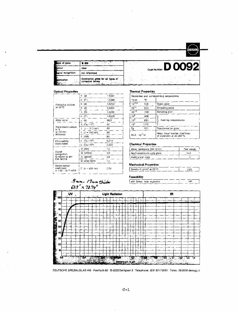
,~ OIgl.,s 11m ~ , - .... !
'~Jour clear ~ ~
~nal recogni1ion not influ81'lCed -.' Ophthalmic ;fau for all. types of
~
. correclive lenses I:.~~:t",n ~.' .. ' '. 0"-:;: "'."" ! ....
Optical Properties n (9) 1,5341
n (F') 1.5298
1,5252
i 1.5231
1,5230
=t~~~~e indices Jrl_~_::-:-; ______ -'-:-:-' __ _
n (D)
i I
, ,
n (C') 1,5208
Abbe value \' (e) 58,3
92
56 Transmission values in % el.;:T-.:.I'.c·._~_3c.1-,3,--nm-,--) __ --,-C-.-__ at 2.0 mm T (/. = 350 nm) 89 thickness
T (SIR) 89
Chromaticity x (D65-10o) 0,314 coordinates y (065-10°) 0,332
o (red) 1.0 Signal Q (yellow) 1,0 recognition O-values as per Q (green) 1.0 DIN 58 216 a (stop light) 1.0
Stress-optical ; coefficient ,e in L02 . 10' 12 m2/N
O.~ 555 nm) 2.70
l
. 'I >t\ ft\ - 17,.. WI thi.~ (3, ~ " x. 7J.7/f"
I .. :: : c <.,' c,~ ~L . Ughl .~ .., f,;90
~, II I
~ 'J I
IL II
~
'" ;,.L~c,'
.
• !
--J
I
,
': ".C:
CodeNumber: D 0092 ..
,""0
Thermal Properties Viscosities and corresponding temperatures
Poise "C
10 '4.5 505 Strain point
10 13 533 Annealing point
107.6 708 Softening paint
10' 806
I. Fo<ming ,empe,.'uces 10' 891
104 1006
Tg 521 Transformation point
93.3 1O-7/K Mean linear thermal coefficient of expansion at 20-300 oC
Chemical Properties
Water resistance DIN 12111 Test results
NalO-donation in !lgJg glass 143
Hydrolytical class 3
Mechanical Properties I Density in g/cm3 at 23°C 2,55
Fuseability
I with Scholt near segments yes
IR
.c>, &zt;;;:;;,;;l;"~~< ,0 ,>,' ~;;"
DEUTSCHE SPEZIALGLAS AG' Postfach 80' 0-3223 Delligsen 2, Telephone: (05187175061 'Telex: 092950desagg d
C-l

SDLAKLEERTM Optically flat, virtually color-free solar glass, cut to size and available in thicknesses from 1 mm to 5.5mm ... produced on a continuous basis to satisfy industry needs
GGl's SOLAKLEER'" is manufactured at the Jeannette Sheet Glass plant in Jeannette. Pennsylvania. which is recognized forthe production of highest Quality sheet glass. The Jeannette manufacturing process produces glass with exceptional lack of "color" - the dull green cast caused by impurities such as iron. Further refinements in the process have produced a low-iron glass that allows a considerable increase in solar energy transmittance. SOLAKLEER has excellent transparency and an optically flat surface. It is manufactured in a broad range of thicknesses from micro-thin 1 mm to 5.Smm, in sheet sizes up to 84"x 9611
and is produced on acontinuing basis.
Applications Typical applications for SO~KLEER include sunlight focusing mirrors. passive solar energy windows for commercial and residential buildings. photovoltaic cells and flat plate collectors.
Green color indicates iron content 01 various types of glass compared with SQLAKLEER. Which has an iron conlent of .057%and ia virtuallycoJorfree
COf'YRJGHT ~ 1980. GENERAl OLASSINTERNATJONAL CORPORATION
Spectral Transmittance (1.0mm SOLAKLEER)
The TSETspecifications shown were measured in the range of 390-1722 nanometers (millimicrons) by Beckman Spectrophotometer equipment in accordance with testing procedure ASTM E 424-71.
Physical Properties Nominal Maximum Weight Thickness Size 2!! 5g. Fl. TSET* 'mm Cui to (,038"-.042"1 ~our s~s .507 91.3:' 2.5mm 1·090"1 60" x. 84" ',83 90.5%
1/8" 84" ):96" '625 90':1
5/32" 84" x 96" 1.976 89.5%
3116" 64" x 96" 2.509 88.8%
13/64" 84" x 96" 2.762 885%
"'Data provided by Battelle Pacific Northwest Laboratories. Richland, INashington.
SOLAKLEER can be tempered upOn reQuest. All tempered glass will conform to Federal Specification 000-4510 and to safety spec. ANSI Z97.1-1975.
For additional information and technical data. please contact: David Balik. Mgr .. Marketing and Industrial Sales. General Glass International Corp.
SDLAKLEER'·
C-2
SOLAKLEER'" Specifications Total Solar Energy 1 mm-91.3% Transmittance: 2.3mm-90.5%
Iron Content: Flatness:
3.1 mm-90.1 % 4mm-89.5% 5mm-BB.B%
5.5 mm-8B.5% 0.057%
Reflective dispersion across the entire mi rror area for 3.1mm glass is better than 2.5 Milliradians.
Index of refraction: 1.52 Density: 2.48 gr/cm' Coefficient of Linear Expansion (@ 0-300°C): Strain Point: Annealing Point: Windload:
534°C RefertoANSIA 134-1-1970 or AAMASpec. 302-7-1971
Weather Resistance: Excellent Specilications are subject tochange without notice
(eM General Glass NTERNATlONAL COAP. 270 NortR Avenue, New Rochelle. NY 10801 Telephone: (914) 235.5900 TWX: 710-563 0636 - 8sllkglas NROH Tetell:: 99 6520 - Balikglss NRDH Cable: Balikglas - New Rochelle
PAINTED IN U.SA

APPENDIX D
BASELINE LAMINATION PROCESS FIXTURE DRA\1ING

.. I I. . I ;. , ~;, I 10
- I . • , . iI 7 I •
, • I .11 I • I ~ I
r'~& -''''r-r-J :~ "I """l
IJ!N-'3rIHh'-"'J(."OP(IIiN); R!II J"'" _ , II I I
.1,.!.;::t .... C"'~ •• ·,. .~.QIA(P7'l ~ .'1 .... ) ~r •
I -~-----! +-<f~ .~ W"('7no - 1._ 1oIrAo.:S~.",S • -~.
~-=-:,--., ---+-- -.. r.1
M'; " ~~~! / • q ~,f.-.... -, l'~S r~.s - r·sD "'881 • I .0,'.: ,tvA
T I I ~ I 8!DCK ASje1
- ,~~ ~~- -
\ --..-.Jt
~ootp6
1\ .....
- -9.00 I 4O-MD 16.aJr.tJ3 'I ~-
--tT'O
t5D- --' -~ .".-
\" .-H """''' H
t I , t "'-.! 'DtfW!(1IIS ]'ERMS&ro~IWC~S ~ MlSI Ylif..~.
__ 4.5Or." //' '2. SJ,,== a"~V,e."47~251J47961'IKAPPIlQK - I) D & DRlU., TRP • .JAISTAL'-~T I¥!I? ~ .D/SrRtICrroNS.
- -- - -_ -I- --~ -
1 II I' I I I I I I I
4. Nfsql( ALL ~~p ED64S ~ CORIJeR,S.
, G
t 'F --+--.. _ - ... .=:.... I+- --r--~ ... 4'D .-tooo ~++-1+1'+1-+'-t± - ,,"71
I-,
I i ,
- 4Q II _4_+'1t-~-j-- '-
cT ~~ ~, -
I ·t--H-++-·j -+ltl -' ~ .; ~ ~-;-.++-t-~~ j . 44()(#.06
~ ... ,u.OS ~
I :,-1±LL1+ii--r-+.·,= ,
r"OOO ,
- I~ ,
-+ -+--j-+1--H--t-+t-l= f.«.7nm
• ,~ t.OS Il-- .. _ .... i --1--. T -:- --;---+ -.-. ----If--~ - II-
= • i 'I' 'I I' --.ti I' E
- -F --
1" - -)T ~ ,c: !l!O.t(3
')' j.. - It ~ . c:L~;; I
•
• Lso "-
L-e.oo.t . .:a TYP
D
, ~4"lS f- f9.53t.03~ -,ciao f~="A'1HRU
- ., ... t ~i.tJOO ~"'- f$lA! .,Ii DOifD .""''''''''0 TYP "CORiJH$ 30PLACt:S ' '" ~ .. "" 9 ~,RT I""'PI'A 5". "'" It.,. •
J:A-l seQ SIlJCE.S.~-'''~O-- .5"~~D'A, ~Ft..AT) "",-
A .00 ,-I-e 4_"" .oo5R
:~ir Y';iiiii;; ri"-~ L:.."'1l:.
2.~ 55.00Z.0!I ,
TfP
~ ..u. TYP I .... J f'7'7r,Dj7f -f'~) 0r.0i5l Bf I r1-C!5t.ooS ~'LO" f--
- ~ P7 PAD
".... Fir
" ~ (2Pl..S,IrfAN<~D-·F·) (,000 ,. I ... ) P4 4~ /'1_) .. F!II<eS <-J ""TAIL-II
• v::L ~r:j. ". ,~-vll"'"
'I/H') """""l , (TYfI/CifI.. 90 PlS)
t/~ ]////t -) I ~~ "\ ~ f%J1 w ... ;- -=- - it --' -
-A. '-.. '-..
' """" i<"",,~ ,,( ~,,'-..'-..,. ~ ~ ~+ - ":';: ,,1111" ".".!.
I _~ ~~'-16""'-2a(""'4?;'S/6~~jOJA ~c""", , ,
f2f!!!f!~;"~~~MPJ V
• SECT,oAi I~ -I~ .!~ (~) 12 7D ..62 DIAl! .~DP(,qp .... ~ -':iI fO PLS SECTION C;- C: SECTION 1-\-A E 12a99JI47E<."v .... i7 (Se}/l7(e-s) .so;4Le; h 9ptge~D·*"
. ...... !f ' . :==..- T .. . I .. . I pll I 10 I . • ..1 • ]I 7 I • I • I 'p , • • I
D-l/2

DISTRIBUTION LIST:
Acurex Corporation (3) Attn: George Sutton
Bob Spencer John Kull
485 Clyde Avenue Mountain View, CA 94042
Aerospace Corporation Attn: Ed Simburger 2350 EI Segundo Blvd. EI Segundo, CA 90266
Alliance Tool Corp. Fresnel Optics Division Attn: Helmut Walter 1300 Mt. Read Blvd. Rochester, NY 14606
Applied Solar Energy corp. (3) Attn: Steve Olah
Frank Ho Ken Ling
15251 E. Don Julian Road City of Industry, CA 91746
ARCO Power Systems Attn: Floyd Blake Suite 307 7061 S. University Blvd. Littleton, CO 80122
Arizona State University (2) Attn: Charles Backus
Robert Sanderson College of Engineering Tempe, AZ 85281
Ray Bahm & Associates Attn: Ray Bahm 2513 Kimberly Court NW Albuquerque, NM 87130
Battelle Attn: Don Carmichael 505 King Avenue Columbus, OH 43201
The BDM Corporation (3) Attn: Tim Lambarski
Wayne Kauffman Bill Schwinkendorf
1801 Randolph Road SE Albuquerque, NM 87111
Boeing Engineering & Const. Co. Attn: Roger Gillette P. O. Box 3707 Seattle, WA 98)24
Burns & Roe, Inc. (2) Attn: G. A. Fontana 800 Kinderkamack Road Oradell, NJ 07649
Chevron Research (2) Attn: John Cape
R. Creek 576 Standard Avenue Richmond, CA 94802
Cyro Industries 697 Route 46 Clifton, NJ 07015
U. S. Dept. of Energy (2) ALO Attn: James Mqrley
Ethan Walker P.O. Box 5400 Albuquerque, NM 87115
U. S. Dept. of Energy (7) Div. of PV Energy Technologies Attn: M. B. Prince (5)
L. A. Ba r ret t A. Scollaro
1000 Independence Ave. SW Washington, DC 20585
E-Systems (2) Attn: Mark O'Neill
A. J. McDanal P. O. Box 226118 Dallas, TX 75266

General Electric Co. At tn: Ron Hodge P. O. Box 527 King of prussia, PA 19406
International Rectifier Attn: Harold Weinstein 235 Kansas Street El Segundo, CA 91214
Intersol Power Corporation Attn: John Sanders 7400 W. Radcliff Avenue Littleton, CO 80123
Jet propulsion Lab (3) Attn: K. Shimada
R. Ferber Solar Data Center
4800 Oak Grove Drive Pasadena, CA 91109
Martin Marietta (4) Attn: S. Broadbent
R. Hein D. Hughes J. Baumann
P. O. Box 179 Denver, CO 80201
Microwave Associates Attn: Jonathon Chapple-Sokol South Avenue MS-116 Burlington, MA 01803
3M Attn: Sanford Cobb Industrial Optics 235 2D15 3M Center St. Paul, MN 55144
Motorola Attn: Keith Kingston GED 8201 E. McDowe1l Scottsdale, AZ 85252
NASA, HQ Attn: John Loria Code RET-l Washington, DC 20546
New Shelter Home Magazine 9317 Shoshone Albuquerque, NM 87111
Oak Ridge National Lab Attn: Steve Kaplan P. O. Box X Oak Ridge, TN 37830
Oklahoma University 571 South university Blvd. Norman, OK
Photowatt (2) Attn: William Taylor
Mike Keeling 2414 W. 14th Street Tempe, AZ 85281
Power Hybrids Attn: Jeff Meyer 1742 Crenshaw Blvd. Torrance, CA 90501
PRC Attn: E. Stirewalt 5201 Leesburg Pike suite 400 Falls Church, VA 22070
Purdue University (2) Attn: Richard Schwartz
Mark Lundstrom Electrical Engineering Dept. West Lafayette, IN 47907
Quantum Specialties Attn: James E. Molle 163 Verde Circle Rohnert Park, CA 94928
Research Triangle Institute Attn: Mayrant Simons Box 12194 Research Triangle Park, NC 27709
SERI (3) Attn: Gene Blakeslee
Lee Cole John Benner
1617 Cole Blvd. Golden, CO 80401
SERI, Library (2) 1536 Cole Blvd., Bldg. #4 Golden, CO 80401
southern Cal Edison Attn: Spencer Carlisle 2244 Walnut Grove Ave. Rosemead, CA 91770
spectrolab Attn: Brian Elm 12500 Gladstone Avenue sylmar, CA 91342
Spire (3) Attn: S. Tobin
M. Nowlan R. Little
Patriots Park Bedford, MA 01730
star Light Energy Attn: J. Furber 1717 18th Street NW Washington, DC 20009
Strategies Unlimited 201 San Antonio Circle suite 205 Mountain View, CA 94040
Solar Attn: Route Santa
Works Paul wilkins
2, Box 274 Fe, NM 87501
Thermo Electron Attn: Ron Scharlack 45 First Avenue Waltham, MA 02154
UNM/NMERI Attn: G. Leigh Campus Box 25 Albuquerque, NM 87131
Varian & Associates (2) Attn: Peter Borden
N. Kaminar 611 Hansen Way K-2l9 Palo Alto, CA 94303
Wright Patterson AFB Attn: Jack Geis AFWAL/POOC Wright Patterson AFB, 08
Wyle Labs (2) Attn: Dave Christenson
George Meares 7800 Governors Drive West Huntsville, AL 35807
Ford Motor Company Plastics, Paint & Vinyl Division Attn: Julie A. ~lilloughby
Sales Dept. P. O. Box 850 Wixom, MI 48096

1133 R. Chaffin 1133 J. Wiczer 1811 R. Assink 1822 J. Sweet
Attn: M. Moss R. Pettit
1823 M. Chamberlain 1845 R. Eagan 2142 B. Rose 2146 M. Garner 2146 B. Hanson 2146 B. Nasby 2146 J. Rodriguez 2146 H. Weaver 9700 E. Beckner 9720 D. Schueler 9721 J. Banas 9721 H. Gerwin 9723 E. Burgess 9724 E. Boes 9724 D. Arvizu 9724 L. Beavis 9724 C. Chiang 9724 M. Edenburn 9724 D. King 9724 A. Maish 9724 M. Rios 9724 C. Stillwell (15) 3141 L. J. Erickson (5) 3151 w. L. Garner (3 ) 3154-3 C. H. Dalin (25)
For DOE/TIC (Unlimited Release) 8214 M. A. Pound