
DC motor position control using fuzzy proportional ... · A 3.70 kW, 240V, 1750 rpm DC motor with...
19
TJFS: Turkish Journal of Fuzzy Systems (eISSN: 1309–1190) An Official Journal of Turkish Fuzzy Systems Association Vol.1, No.1, pp. 36-54, 2010. 36 DC motor position control using fuzzy proportional-derivative controllers with different defuzzification methods Manafeddin Namazov Cumhuriyet University, Faculty of Engineering, Department of Electrical & Electronics Engineering, 58140 Sivas, Turkey E-mail: [email protected] Onur Basturk* Cumhuriyet University, Faculty of Engineering, Department of Electrical & Electronics Engineering, 58140 Sivas, Turkey E-mail: [email protected] *Corresponding author Received: February 1, 2010 - Revised: April 2, 2010 – Accepted: May 26, 2010 Abstract This paper presents the design of a fuzzy control system to control the position of a DC motor. The motor was modelled and converted to a subsystem in Simulink. First, a crisp proportional-derivative (PD) controller was designed and tuned using a Simulink block instead of conventional tuning methods such as hand-tuning or Ziegler-Nichols frequency response method. Then a fuzzy proportional-derivative (FPD) controller was designed and system responses of FPDs with different defuzzification methods were investigated. A disturbance signal was also applied to the input of the control system. FPD controller succeeded to reject the disturbance signal without further tuning of the parameters whereby crisp PD controller failed. Keywords: Fuzzy logic, DC motor position control, Fuzzy proportional-derivative controller, Response optimization, Ziegler-Nichols method 1. Introduction Because of their high reliabilities, flexibilities and low costs, DC motors are widely used in industrial applications, robot manipulators and home appliances where speed and position control of motor are required. PID controllers are commonly used for motor control applications because of their simple structures and intuitionally comprehensible control algorithms. Controller parameters are generally tuned using hand-tuning or Ziegler-Nichols frequency response method. Both of these methods have successful results but long time and effort are required to obtain a satisfactory system
Transcript of DC motor position control using fuzzy proportional ... · A 3.70 kW, 240V, 1750 rpm DC motor with...

TJFS: Turkish Journal of Fuzzy Systems (eISSN: 1309–1190)
An Official Journal of Turkish Fuzzy Systems Association
Vol.1, No.1, pp. 36-54, 2010.
36
DC motor position control using fuzzy
proportional-derivative controllers with
different defuzzification methods
Manafeddin Namazov
Cumhuriyet University, Faculty of Engineering,
Department of Electrical & Electronics Engineering, 58140 Sivas, Turkey
E-mail: [email protected]
Onur Basturk*
Cumhuriyet University, Faculty of Engineering,
Department of Electrical & Electronics Engineering, 58140 Sivas, Turkey
E-mail: [email protected]
*Corresponding author
Received: February 1, 2010 - Revised: April 2, 2010 – Accepted: May 26, 2010
Abstract
This paper presents the design of a fuzzy control system to control the position of a DC
motor. The motor was modelled and converted to a subsystem in Simulink. First, a crisp
proportional-derivative (PD) controller was designed and tuned using a Simulink block
instead of conventional tuning methods such as hand-tuning or Ziegler-Nichols
frequency response method. Then a fuzzy proportional-derivative (FPD) controller was
designed and system responses of FPDs with different defuzzification methods were
investigated. A disturbance signal was also applied to the input of the control system.
FPD controller succeeded to reject the disturbance signal without further tuning of the
parameters whereby crisp PD controller failed.
Keywords: Fuzzy logic, DC motor position control, Fuzzy proportional-derivative
controller, Response optimization, Ziegler-Nichols method
1. Introduction
Because of their high reliabilities, flexibilities and low costs, DC motors are widely
used in industrial applications, robot manipulators and home appliances where speed
and position control of motor are required. PID controllers are commonly used for
motor control applications because of their simple structures and intuitionally
comprehensible control algorithms. Controller parameters are generally tuned using
hand-tuning or Ziegler-Nichols frequency response method. Both of these methods have
successful results but long time and effort are required to obtain a satisfactory system

37
response. Two main problems encountered in motor control are the time-varying nature
of motor parameters under operating conditions and existence of noise in system loop.
Analysis and control of complex, nonlinear and/or time-varying systems is a
challenging task using conventional methods because of uncertainties. Fuzzy set theory
(Zadeh, 1965) which led to a new control method called Fuzzy Control which is able to
cope with system uncertainties. One of the most important advantages of fuzzy control
is that it can be successfully applied to control nonlinear complex systems using an
operator experiences or control engineering knowledge without any mathematical
model of the plant (Assilian, 1974), (Kickert, 1976).
There are many papers about DC motor fuzzy control system design. Lin et. al.
compared PID and FLC for position control and observed that FLC performed better
than PID (Lin, 1994). Azevedo et. al. have shown that FLC is less sensitive than PID to
load variations (Azevedo, 1993). Bal et. al. designed an FLC for an ultrasonic motor
which has a different operation principle than electromagnetic motors (Bal, 2004).
Mishra et. al. made a comparison between PID and FLC for servomotor control and
described that PID parameters had to be tuned again under variations of plant
parameters or noise wherever FLC parameters had not (Mishra, 1998). Kwon et. al.
designed a PI controller for a brushless DC motor and built an adaptive fuzzy tuning
system to modify the controller parameters under load variations during operation
(Kwon, 2003). M.H. Zadeh et. al. explained that one of the best methods for control of a
DC motor with time-varying parameters was fuzzy sliding mode control (Zadeh, 2006).
Namazov et. al. designed a relay type fuzzy controller in control of double integrator
systems which can be used to model many mechanical, hydraulic and electrical objects
such as DC motors and observed that fuzzy controller was able to reject the noise signal
applied to the input of system (Namazov, 2007).
DC motor control is generally realized by adjusting the terminal voltage applied to the
armature but other methods such as adjusting the field resistance, inserting a resistor in
series with the armature circuit are also available (Chapman, 2005).
Ziegler-Nichols frequency response method is usually used to adjust the parameters of
the PID controllers. However, it is needed to get the system into the oscillation mode to
realize the tuning procedure. But it’s not always possible to get most of the
technological plants into oscillation. The proposed approach uses both fuzzy controllers
and response optimization method to obtain the approximate values of the controller
parameters. Then the parameters may be slightly varied to obtain the user-defined
performance of the real-time control system. Thus, it’s an actual problem to design
adaptive PID controllers without getting the system into the oscillation mode.
The rest of this paper is organized as follows. In the next section, the mathematical
model of a dc motor is used to obtain a transfer function between shaft position and
applied armature voltage. This model is then built in MATLAB Simulink. In Section 3,
design and tuning of proportional-integral-derivative (PID) controllers are reviewed and
a crisp PD control system is designed in Simulink with the proposed design procedure.
In Section 4, it’s mentioned about the fuzzy logic controller design issues and a fuzzy
proportional-derivative controller is designed with the proposed approach. Some of the

38
commonly used defuzzification methods are discussed and system responses with
different defuzzification methods are compared. Finally disturbance rejection
capabilities of the designed controllers are investigated.
2. DC motor model
In armature control of separately excited DC motors, the voltage applied to the armature
of the motor is adjusted without changing the voltage applied to the field. Figure 1
shows a separately excited DC motor equivalent model.
Figure 1. DC motor model
where armature voltage ( )
armature resistance ( )
armature inductance ( )
armature current ( )
back emf ( )
angular speed ( )
motor torque ( )
angular position of rotor shaft ( )
rotor inertia ( )
viscous friction coefficient ( )
torque constant ( )
back emf constant ( )
Let us combine the upper equations together:

39
Laplace transforms of (5) and (6) are:
If current is obtained from (8) and substituted in (7) we have
Then the relation between rotor shaft speed and applied armature voltage is represented
by transfer function:
The relation between position and speed is:
Then the transfer function between shaft position and armature voltage at no-load is:
Figure 2 shows the DC motor model built in Simulink. Motor model was converted to a
2-in 2-out subsystem. Input ports are armature voltage (Va) and load torque (Tload) and
the output ports are angular speed in (w) and position (teta).

40
Figure 2. Simulink model
A 3.70 kW, 240V, 1750 rpm DC motor with the below parameters was used:
3. Proportional-integral-derivative (PID) controller
PID controllers are widely used in industrial control applications due to their simple
structures, comprehensible control algorithms and low costs. Figure 3 shows the
schematic model of a control system with a PID controller.
Figure 3. PID control system
Control signal is a linear combination of error , its integral and derivative.

41
where = proportional gain
= integral gain
= derivative gain
= integral time
= derivative time
If the controller is digital, then the derivative term may be replaced with a backward
difference and the integral term may be replaced with a sum. For a small constant
sampling time , (14) can be approximated as:
3.1 Tuning PID parameters
PID controllers are usually tuned using hand-tuning or Ziegler-Nichols methods
(Jantzen, 2007).
Hand-tuning is generally used by experienced control engineers based on the rules
shown in Table 1. But these rules are not always valid. For example if an integrator
exists in the plant, then increasing results in a more stable control.
Table 1. Hand-tuning rules
A simple hand-tuning procedure is as follows:
1. Remove derivative and integral actions by setting and
2. Tune such that it gives the desired response except the final offset value from
the set point
3. Increase slightly and adjust to dampen the overshoot
4. Tune such that final offset is removed
5. Repeat steps from 3 until is as large as possible

42
The disadvantage of this method is that it should take a long time to find the optimal
values. Another method to tune PID parameters is Ziegler-Nichols frequency response
method. The procedure is as follows:
1. Increase until system response oscillates with a constant amplitude and
record that gain value as (ultimate gain)
2. Calculate the oscillation period and record it as
3. Tune parameters using Table 2
Table 2. Ziegler-Nichols rules
Ziegler-Nichols frequency response method gives poor results especially for the systems
with a time lag much greater than the dominating time constant (Jantzen, 2007).
Damping is generally poor. Rules work better for PID controllers than PI controllers and
it is not stated how to calculate the parameters for a PD controller.
Another method proposed by Ziegler and Nichols is the reaction curve or step response
method where the unit-step response of the plant is used to adjust parameters. But the
plant must not involve any integrators or dominant complex conjugate poles for this
method to apply (Ogata, 1997).
3.2 PD controller design
A PD controller was designed to control the DC motor. Control signal of a PD
controller is as follows:
Controller parameters were tuned using Signal Constraint block of Simulink Response
Optimization Toolbox instead of conventional methods.
Signal Constraint is a block where response signals can be graphically constrained and
model parameters should be automatically optimized to obtain the performance
requirements (Mathworks, 2008).
Performance criteria were specified as:
Rise time
Settling time
Maximum overshoot
Steady state error

43
The objective in control system design is to find a control signal that satisfies the
performance requirements (Veremey).
Assume that the mathematical model of the plant can be represented by a differential
equation:
where time vector
-vector of state variables
-control vector
-disturbance vector
Also assume that controller is represented by:
where
– differential operator
– transfer matrix of the controller
Assume that transfer matrix structure is known and vector of controller parameters to be
tuned ( ) is also included in this structure.
Determine a reasonable set which represents the behaviour of closed loop system at
any time instant. It is obvious that this set should only be obtained by the choice of
vector.
Then the objective is to find an vector that satisfies the performance requirements.
3.3 Simulink implementation
Figure 4 shows the PD control system designed in MATLAB Simulink where controller
coefficients were adjusted using the Signal Constraint block. Integral coefficient of PID
controller was set to zero (i.e. ).

44
Figure 4. Crisp PD control system
Figure 5 shows the optimization process of controller parameters where and were
obtained as , respectively.
Figure 5. Optimization of PD parameters
Overshoot is not desired especially in position control systems. It can be seen from
Figure 5 that Signal Constraint block adjusted the parameters such that a very small
overshoot occurs. Table 3 shows the values of the performance criteria obtained with
the adjusted controller parameters.
Table 3. Performance specifications for crisp PD control system
0.64s
0.88s
0.2%
None

45
Figure 6 shows output and control signals of PD control system with adjusted
parameters.
4. Fuzzy logic controller
A fuzzy logic controller has four main components as shown in Figure 7: fuzzification
interface, inference mechanism, rule base and defuzzification interface.
FLCs are complex, nonlinear controllers. Therefore it’s difficult to predict how the rise
time, settling time or steady state error is affected when controller parameters or control
rules are changed. On the contrary, PID controllers are simple, linear controllers which
consist of linear combinations of three signals.
Figure 6. Output and control signals for crisp PD control system

46
Figure 7. Fuzzy logic controller
Implementation of an FLC requires the choice of four key factors (Mamdani, 1977):
number of fuzzy sets that constitute linguistic variables, mapping of the measurements
onto the support sets, control protocol that determines the controller behaviour and
shape of membership functions. Thus, FLCs can be tuned not just by adjusting
controller parameters but also by changing control rules, membership functions etc.
Rule base, inference mechanism and defuzzification methods are the sources of
nonlinearities in FLCs. But it’s possible to construct a rule base with linear input-output
characteristics. For an FLC to become a linear controller with a control signal
where is “error” and is “change of error”, some conditions must be
satisfied (Jantzen, 2007): 1. Support sets of input linguistic variables must be large enough so that input
values stay in limits.
2. Linguistic values must consist of symmetric triangular fuzzy sets that intercept
with neighbouring sets at a membership value of so that for any time
instant, membership values add to 1.
3. Rule base must consist of -combinations of all fuzzy sets.
4. Output linguistic variables must consist of singleton fuzzy sets positioned
at the sum of the peak positions of input fuzzy sets.
5. should be multiplication and defuzzification method must be “centre of
gravity” (COGS).
4.1 FPD controller design
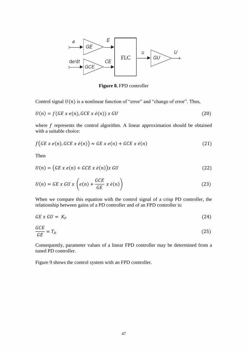
Figure 8 shows an FPD controller that acts on the same signals with a PD controller but
the control strategy is constructed as fuzzy rules (Jantzen, 2007).
47
Figure 8. FPD controller
Control signal is a nonlinear function of “error” and “change of error”. Thus,
where represents the control algorithm. A linear approximation should be obtained
with a suitable choice:
Then
When we compare this equation with the control signal of a crisp PD controller, the
relationship between gains of a PD controller and of an FPD controller is:
Consequently, parameter values of a linear FPD controller may be determined from a
tuned PD controller.
Figure 9 shows the control system with an FPD controller.

48
Figure 9. Control system with an FPD controller
4.2 Defuzzification methods
Defuzzification interface uses the implied fuzzy sets or the overall implied fuzzy set to
obtain a crisp output value. There are many defuzzification methods but the most
common methods are as follows:
1) Center of gravity (COG)
2) Bisector of area (BOA)
3) Smallest of maximum (SOM)
4) Mean of maximum (MOM)
5) Largest of maximum (LOM)
For discrete sets COG is called center of gravity for singletons (COGS) where the crisp
control value is the abscissa of the center of gravity of the fuzzy set. is
calculated as follows:
where is a point in the universe of the conclusion and is the
membership value of the resulting conclusion set. For continuous sets summations are
replaced by integrals.
The bisector of area (BOA) defuzzification method calculates the abscissa of the
vertical line that divides the area of the resulting membership function into two equal
areas. For discrete sets, is the abscissa that minimizes
Here is the index of the largest abscissa . BOA is a computationally complex
method.

49
Another approach to obtain the crisp value is to choose the point with the highest
membership. There may be several points in the overall implied fuzzy set which have
maximum membership value. Therefore it’s a common practice to calculate the mean
value of these points. This method is called mean of maximum (MOM) and the crisp
value is calculated as follows:
Here is the (crisp) set of indices where reaches its maximum , and is
its cardinality (the number of members).
One can also choose the leftmost point among the points which have maximum
membership to the overall implied fuzzy set. This method is called smallest of
maximum (SOM) or the leftmost maximum (LM) defuzzification method. Crisp value is
calculated as follows:
Another possibility is to choose the rightmost point among the points which have
maximum membership to the overall implied fuzzy set. This method is called largest of
maximum (LOM) or the rightmost maximum (RM) defuzzification method where crisp
value is calculated as:
4.3 Simulink implementation
Inputs of FPD are “error” and “change of error” where the output is “control”. Input and
output variables of FPD consist of seven fuzzy sets namely NB (negative big), NM
(negative medium), NS (negative small), Z (zero), PS (positive small), PM (positive
medium) and PB (positive big) as shown in Figure 10(a) and (b). Table 4 shows fuzzy
rules.
(a) Fuzzy input variables “error” and “change of error”
(b) Fuzzy output variable “output”
Figure 10. Fuzzy input-output variables

50
Table 4. Fuzzy rules
Figure 11 shows the fuzzy PD control system designed in Simulink.
Figure 11. Fuzzy PD control system
Different defuzzification methods were used to obtain the control signal. Table 5 shows
the tuned values of the controller parameters for different defuzzification methods.
Table 5. Controller parameters for different defuzzification methods
Method
Bisector 2.2484 0.01
SOM 4.1236 0.01
MOM 4.5538 0.1901
LOM 4.7623 0.1649
Figure 12(a)-(d) shows the system responses and control signals for the fuzzy control
systems with different defuzzification methods.
Table 6 shows the values of the performance criteria for different defuzzification
methods with the tuned controller parameters.

51
Disturbance rejection is important in controller design. The controller must be able to
dampen out the effects of disturbance signals existing in the system loop. Therefore a
disturbance signal (Gaussian type noise with zero mean and 0.05 variance) was applied
to the input of the control system as shown in Figure 13.
Figure 14 shows the applied disturbance signal and Figure 15 shows the system
response and error signals.
5. Conclusions and future work
Parameters of PD and FPD controllers were tuned using a Simulink block instead of
conventional tuning methods. Initial values of parameters were defined as
and the new parameter values were adjusted in just a few iterations as shown in
Figure 5. Thus the time and effort for tuning parameters decreased considerably.
Figure 12 and Table 6 show that different defuzzification methods result in different
performance and parameters as well as different control signals. SOM defuzzification
method had the best performance in this particular application.
FPD controller rejected the disturbance signal without further tuning of the controller
parameters. However, PD controller was unable to reject the disturbance signal and it
failed to satisfy the performance requirements.
This paper presents the optimization of the controller parameters via a Simulink block
instead of conventional tuning methods. The performance criteria are defined in time
domain where the transient response of the system to a step input was considered. As a
future work, a fuzzy control system will be designed using various performance
measures commonly encountered in optimal control theory (optimal time, optimal
energy consumption etc.). After obtaining the controller parameters, “soft-tuning” fuzzy
controllers will be designed to vary the parameters in a fuzzy interval. Thus, the
variation of the controller parameters between maximum and minimum values will be
considered as fuzzy.

52
Figure 12. Output and control signals for different defuzzification methods
Table 6. Performance specifications for fuzzy PD control system
Method
Bisector 0.97 1.26 None 0.2
SOM 0.68 0.91 None 0.2
MOM 0.97 1.16 1 1
LOM 0.83 1 0.2 0.2
(a) Bisector (b) SOM
(c) MOM (d) LOM

53
Figure 13. FPD control system with a disturbance signal at the input
Figure 14. Disturbance signal
Figure 15. System response and error
References
Assilian, S. and Mamdani, E.H., An Experiment in Linguistic Synthesis with a Fuzzy
Logic Controller. International Journal of Man-Machine Studies, 7(1), 1-13, 1974.
Azevedo, H.R., Brandao, S.F.M. and Mota Alves, J.B., A Fuzzy Logic Controller for dc
Motor Position Control. IEEE 2nd International Workshop on Emerging Technologies
and Factory Automation. Design and Operations of Intelligent Factories. Workshop
Proceedings, 18-27, 1993.

54
Bal, G., Bekiroglu, E., Demirbas, S. and Colak, I., Fuzzy logic based DSP controlled
servo position control for ultrasonic motor. Energy Conversion and Management, 45,
3139–3153, 2004.
Chapman, S.J., Electric Machinery Fundamentals, 4th edition, New York: McGraw
Hill, 2005.
Jantzen, J., Foundations of Fuzzy Control, WS: John Wiley & Sons, Ltd., 2007.
Kickert, W. J. M. and van Nauta Lemke, H. R., Application of a Fuzzy Controller in a
Warm Water Plant. Automatica, 12(4), 301-308, 1976.
Kwon, C.J., Han, W.Y., Kim, S.J. and Lee C.G., Speed controller with adaptive fuzzy
tuning for BLDC motor drive under load variations. SICE Annual Conference,
3118-3121, 2003.
Lin, P.H., Hwang, S. and Chou, J., Comparison on Fuzzy Logic and PID Controls for a
DC Motor Position Controller. Conference Record of the 1994 IEEE Industry
Applications Society Annual Meeting, 1930-1935, 1994.
Mamdani, E. H., Application of Fuzzy Logic to Approximate Reasoning Using
Linguistic Synthesis. IEEE Transactions on Computers, 26(12), 1182-1191, 1977.
Mathworks Inc., Simulink® Response Optimization™ Getting Started Guide, 3rd
printing, 2008.
Mishra, M.K., Kothari, A.G., Kothari, D.P. and Ghosh, A., Development of a Fuzzy
Logic Controller for Servo Systems. IEEE Region 10 International Conference on
Global Connectivity in Energy, Computer, Communication and Control (TENCON '98),
204-207, 1998.
Namazov, M., Samet, R. and Huseynov, R., Modelling and Simulation of the Fuzzy
Relay Type Controller for Solving the Double Integrator Control Problems. Proceedings
of 9th WSEAS International Conference on Automatic Control, Modeling&Simulation,
7-11, 2007.
Ogata, K., Modern Control Engineering, 3rd edition, NJ: Prentice Hall, 1997.
Veremey, E.I. and Pogojev, S.B., Nonlinear Control Design Blockset [Online]
Available: http://matlab.exponenta.ru/nonlinecondes/book1/preface.php
Zadeh, L. A., Fuzzy Sets. Information and Control, 8, 338-353, 1965.
Zadeh, M. H., Yazdian, A. and Mohamadian, M., Robust Position Control in DC Motor
by Fuzzy Sliding Mode Control. International Symposium on Power Electronics,
Electrical Drives, Automation and Motion (SPEEDAM 2006), 1413-1418, 2006.