DB GB FL IBS SC/I-T - Power/mation | Strategic … IBS SC/I-T 2 6154A Table of Contents 1 FL IBS...
58
6154A 1 FL IBS SC/I-T 09/2001 Data Sheet 6154A Product Description INTERBUS/Ethernet gateway with Generation 4 functions. Features – Ethernet twisted-pair interface (10BASE-T/100BASE-TX) – Supported protocols: TCP/UDP, SNMPv2, BootP, TFTP, HTTP, and ICMP (Ping) – Integrated web server – Integrated gateway function – Complete Generation 4 functionality (INTERBUS master) – Configuration and parameterization via CMD G4 – INTERBUS protocol (EN 50254) – Comprehensive system diagnostics – User-defined addressing – PCP 4.x – Driver software for Windows NT 4.0, Windows 2000, and SUN Solaris – Software interface kit for other Unix systems Figure 1 FL IBS SC/I-T Applications – Connection of a complete INTERBUS system to Ethernet TCP/IP – Exchange of INTERBUS data using host computers via Ethernet 6 1 5 4 0 0 0 1 U L R e s e t 1 0 0 F D C O L X M T R C V F L I B S S C / I - T O r d . - N o . 2 8 3 1 0 6 0 1 0 / 1 0 0 R D Y / R U N B S A F A I L P F I N T E R B U S R E M O T E 0 0 A 0 4 5 1 B 8 D 6 1 5 4 0 0 0 0 Generation 4 INTERBUS/Ethernet Gateway
Transcript of DB GB FL IBS SC/I-T - Power/mation | Strategic … IBS SC/I-T 2 6154A Table of Contents 1 FL IBS...

6154A 1
FL IBS SC/I-T
09/2001Data Sheet 6154A
Product Description
INTERBUS/Ethernet gateway with Generation 4 functions.
Features
– Ethernet twisted-pair interface (10BASE-T/100BASE-TX)
– Supported protocols: TCP/UDP, SNMPv2, BootP, TFTP, HTTP, and ICMP (Ping)
– Integrated web server
– Integrated gateway function
– Complete Generation 4functionality (INTERBUS master)
– Configuration and parameterization via CMD G4
– INTERBUS protocol (EN 50254)
– Comprehensive system diagnostics
– User-defined addressing
– PCP 4.x
– Driver software for Windows NT 4.0, Windows 2000, and SUN Solaris
– Software interface kit for other Unix systemsFigure 1 FL IBS SC/I-T
Applications
– Connection of a complete INTERBUS system to Ethernet TCP/IP
– Exchange of INTERBUS data using host computers via Ethernet
� � � � � � � �
� �
� �
� � �
�
� � �
� � �
� � �
� � � � � � � � � � � � � � �� � � � � � � � � ! � � � �
� � � � � �
� " � � � �
� � #
� # � �
$ �
� � � % � � � �� % � � � %
� � # � � � � �
� � � � � � � �
Generation 4 INTERBUS/Ethernet Gateway

FL IBS SC/I-T
2 6154A
Table of Contents
1 FL IBS SC/I-T Gateway Structure ...........................................................................................4
2 Local Status and Diagnostic Indicators ...................................................................................5
3 Installation and Mounting/Removal .........................................................................................6
3.1 Mounting ....................................................................................................................6
4 Connecting the Supply Voltage ...............................................................................................7
5 Ethernet Interface ....................................................................................................................9
5.1 Pin Assignment of Crossover/1:1 Cables ..................................................................9
5.2 Connecting Cables Between Ethernet Components ..................................................10
6 Startup .....................................................................................................................................11
6.1 Starting the Firmware ................................................................................................11
6.2 Sending BootP Requests ...........................................................................................11
7 Assigning an IP Address Using the Factory Manager .............................................................12
7.1 BootP .........................................................................................................................12
7.2 Manually Entering the MAC Address in theAdd New Ethernet Device Dialog Box in the Factory Manager ..................................14
8 Selecting IP Addresses ...........................................................................................................15
8.1 Possible Address Combinations ...............................................................................16
9 Subnet Masks ..........................................................................................................................17
9.1 Structure of the Subnet Mask ....................................................................................17
10 Web-Based Management ........................................................................................................19
10.1 Calling Web-Based Management (WBM) ..................................................................19
10.2 Structure of the Web Pages .......................................................................................20
10.3 Layout of the Web Pages ..........................................................................................20
10.4 Password Protection ..................................................................................................20
11 Firmware Update .....................................................................................................................21
11.1 Firmware Update Using The Factory Manager ..........................................................21
11.2 Firmware Update Using Web-Based Management (WBM) Without the Factory Manager23
12 Ethernet Communication .........................................................................................................24
13 Trap Generation ......................................................................................................................27
13.1 Representation of Traps in the Factory Manager (Trap Receiver) ............................27
13.2 Traps for the FL IBS SC/I-T .......................................................................................27
13.3 Defining the Trap Receiver .........................................................................................28
FL IBS SC/I-T
6154A 3
14 Management Information Base - MIB ......................................................................................29
14.1 Standard MIBs: ..........................................................................................................29
14.2 Private MIBs ............................................................................................................... 36
15 Meaning of the 7-Segment Display .........................................................................................52
16 Technical Data .........................................................................................................................54

FL IBS SC/I-T
4 6154A
General Information
WarningIf these instructions are not followed there is a danger of damage to equipment and/or serious personal injury. Only qualified personnel may start up and operate these devices. According to the safety instructions in this text, qualified personnel are persons who are authorized to start up, to ground and to mark devices, systems, and equipment according to the standards of safety technology. In addition, these persons must be familiar with all warning instructions and maintenance measures in this text.
WarningThe FL IBS SC/I-T module is designed exclusively for SELV operation according to IEC 950/EN 60950/VDE 0805.
ShieldingThe shielding ground of the connected twisted-pair cables is electrically connected with the female connector. When connecting network segments, avoid ground loops, potential transfers, and voltage equalization currents using the braided shield.
ESDThe modules are fitted with electrostatically sensitive components. Exposure to electric fields or charge imbalance may damage or adversely affect the life of the modules. The following protective measures must be taken when using electrostatically sensitive modules:
Create an electrical equipotential bonding between yourself and your surroundings, e.g., using an ESD wristband, which is connected to the grounded DIN rail on which the module will be mounted.
HousingOnly authorized Phoenix Contact personnel are permitted to open the housing.
FL IBS SC/I-T
6154A 5
1 FL IBS SC/I-T Gateway Structure
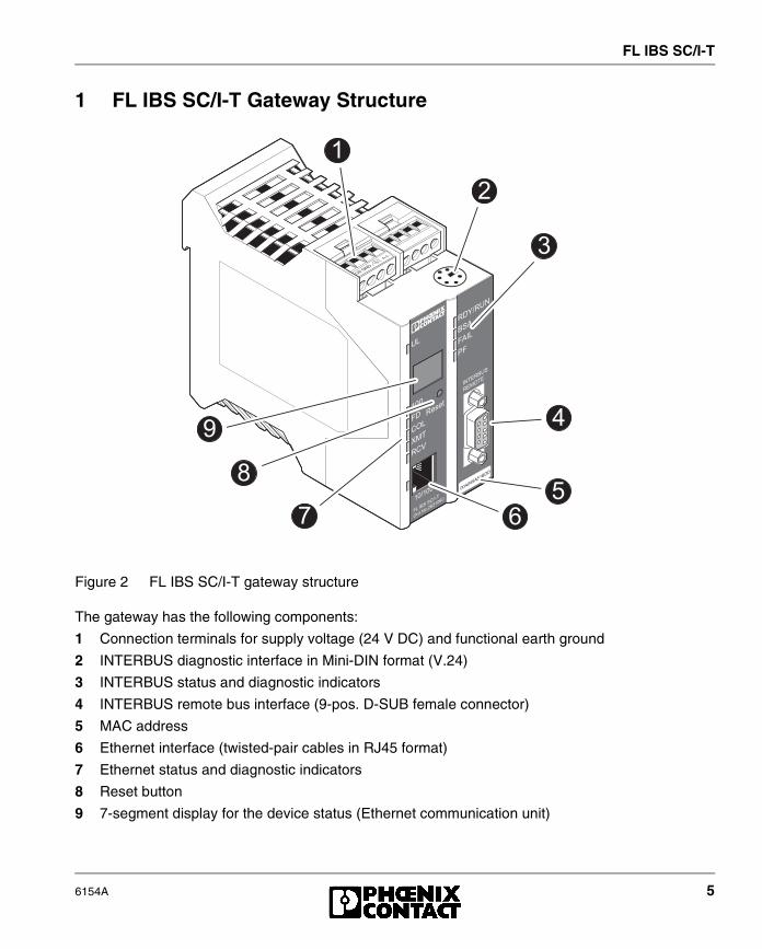
Figure 2 FL IBS SC/I-T gateway structure
The gateway has the following components:
1 Connection terminals for supply voltage (24 V DC) and functional earth ground
2 INTERBUS diagnostic interface in Mini-DIN format (V.24)
3 INTERBUS status and diagnostic indicators
4 INTERBUS remote bus interface (9-pos. D-SUB female connector)
5 MAC address
6 Ethernet interface (twisted-pair cables in RJ45 format)
7 Ethernet status and diagnostic indicators
8 Reset button
9 7-segment display for the device status (Ethernet communication unit)
�
!
&
�
�
��
'
FL IBS SC/I-T
6 6154A
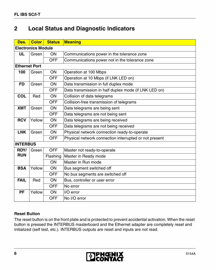
2 Local Status and Diagnostic Indicators
Reset ButtonThe reset button is on the front plate and is protected to prevent accidental activation. When the reset button is pressed the INTERBUS masterboard and the Ethernet adapter are completely reset and initialized (self test, etc.). INTERBUS outputs are reset and inputs are not read.
Des. Color Status MeaningElectronics Module
UL Green ON Communications power in the tolerance zone
OFF Communications power not in the tolerance zone
Ethernet Port100 Green ON Operation at 100 Mbps
OFF Operation at 10 Mbps (if LNK LED on)
FD Green ON Data transmission in full duplex mode
OFF Data transmission in half duplex mode (if LNK LED on)
COL Red ON Collision of data telegrams
OFF Collision-free transmission of telegrams
XMT Green ON Data telegrams are being sent
OFF Data telegrams are not being sent
RCV Yellow ON Data telegrams are being received
OFF Data telegrams are not being received
LNK Green ON Physical network connection ready-to-operate
OFF Physical network connection interrupted or not present
INTERBUSRDY/RUN
Green OFF Master not ready-to-operate
Flashing Master in Ready mode
ON Master in Run mode
BSA Yellow ON Bus segment switched off
OFF No bus segments are switched off
FAIL Red ON Bus, controller or user error
OFF No error
PF Yellow ON I/O error
OFF No I/O error

FL IBS SC/I-T
6154A 7
3 Installation and Mounting/Removal
Install the FL IBS SC/I-T on a clean DIN rail according to DIN EN 50 022 (Phoenix Contact: item NS 35…). To avoid contact resistance only use clean, corrosion-free DIN rails. End clamps should be mounted on both sides of the module to stop the terminals from slipping on the DIN rail.
Connect the DIN rail to the functional earth ground using a grounding terminal block. Connect the module functional earth ground terminal to the DIN rail with as low a level of impedance as possible. The maximum cable length must not exceed 50 cm (19.69 in.)
3.1 Mounting
1. Place the module onto the DIN rail from above. The upper holding keyway must be hooked onto the top edge of the DIN rail.
2. Push the module from the front towards the mounting surface.
3. Once the module has been snapped on properly, check that it is fixed securely on the DIN rail.
FL IBS SC/I-T
8 6154A
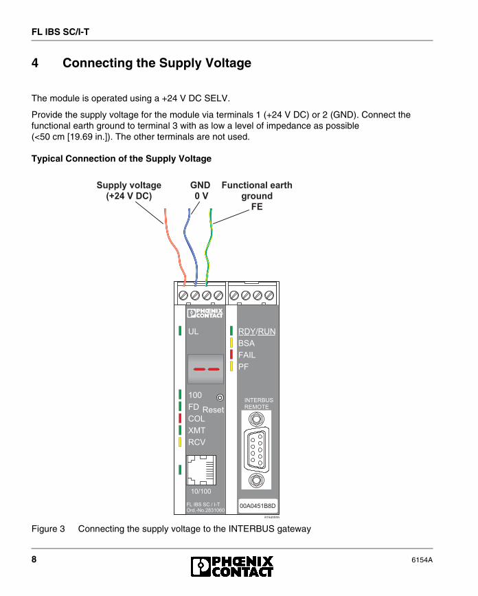
4 Connecting the Supply Voltage
The module is operated using a +24 V DC SELV.
Provide the supply voltage for the module via terminals 1 (+24 V DC) or 2 (GND). Connect the functional earth ground to terminal 3 with as low a level of impedance as possible (<50 cm [19.69 in.]). The other terminals are not used.
Typical Connection of the Supply Voltage
Figure 3 Connecting the supply voltage to the INTERBUS gateway
� � � � � � � �
� �
� �
� � �
�
� � �
� � �
� � �
� � � � � � � � � � � � � � �� � � � � � � � � ! � � � �
� � � � � �
� " � � � �
� � #
� # � �
$ �
� � � % � � � �� % � � � %
� � # � � � � �
� � � � � � � � � � � � � � � � � � � � �
� � �� � � �
� � � � � � � � � � � � �� � � � � �
� �
FL IBS SC/I-T
6154A 9
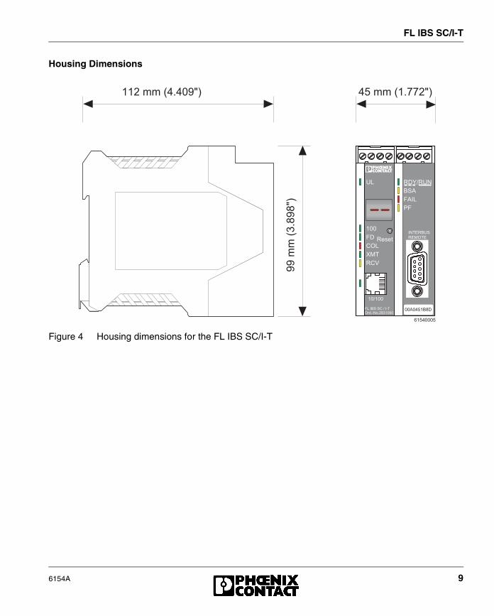
Housing Dimensions
Figure 4 Housing dimensions for the FL IBS SC/I-T
� � � � ( ( � ) � � � � ' * +
''�(
(�)!� ' *+
� � � � � � � �
� � � ( ( � ) � � & & � * +
� �
� �
� � �
�
� � �
� � �
� � �
� � � � � � � � � � � � � � �� � � � � � � � � ! � � � �
� � � � � �
� " � � � �
� � #
� # � �
$ �
� � � % � � � �� % � � � %
� � # � � � � �
FL IBS SC/I-T
10 6154A
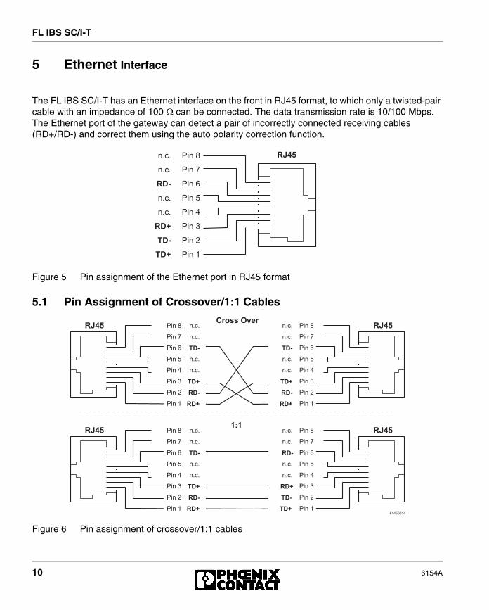
5 Ethernet Interface
The FL IBS SC/I-T has an Ethernet interface on the front in RJ45 format, to which only a twisted-pair cable with an impedance of 100 � can be connected. The data transmission rate is 10/100 Mbps. The Ethernet port of the gateway can detect a pair of incorrectly connected receiving cables (RD+/RD-) and correct them using the auto polarity correction function.
Figure 5 Pin assignment of the Ethernet port in RJ45 format
5.1 Pin Assignment of Crossover/1:1 Cables
Figure 6 Pin assignment of crossover/1:1 cables
$ , - � �
$ , - � �
$ , - � !
$ , - � �
$ , - � �
$ , - � �
$ , - � &
$ , - �
� �
� !
" � �
" � !
- � . �
- � . �
- � . �
- � . �
" # � $
$ , - � �
$ , - � �
$ , - � !
$ , - � �
$ , - � �
$ , - � �
$ , - � &
$ , - �
" � �
" � !
� �
� !
- � . �
- � . �
- � . �
- � . �
$ , - � �
$ , - � �
$ , - � !
$ , - � �
$ , - � �
$ , - � �
$ , - � &
$ , - �
" � �
" � !
� �
� !
- � . �
- � . �
- � . �
- � . �
" # � $" # � $� � � % % � & � � �
$ , - � �
$ , - � �
$ , - � !
$ , - � �
$ , - � �
$ , - � �
$ , - � &
$ , - �
" � �
" � !
� �
� !
- � . �
- � . �
- � . �
- � . �
$ , - � �
$ , - � �
$ , - � !
$ , - � �
$ , - � �
$ , - � �
$ , - � &
$ , - �
� �
� !
" � �
" � !
- � . �
- � . �
- � . �
- � . �
� � � � � � � �
" # � $" # � $' ( '
FL IBS SC/I-T
6154A 11
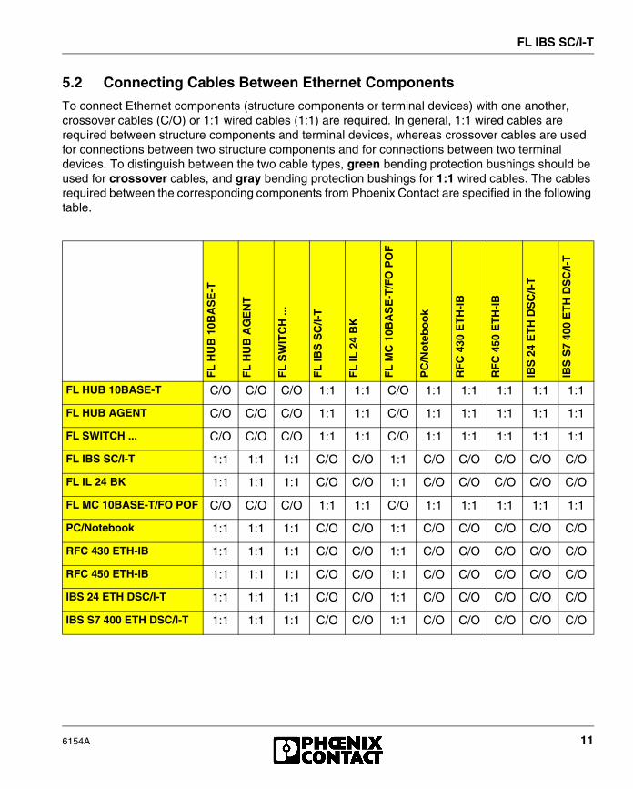
5.2 Connecting Cables Between Ethernet Components
To connect Ethernet components (structure components or terminal devices) with one another, crossover cables (C/O) or 1:1 wired cables (1:1) are required. In general, 1:1 wired cables are required between structure components and terminal devices, whereas crossover cables are used for connections between two structure components and for connections between two terminal devices. To distinguish between the two cable types, green bending protection bushings should be used for crossover cables, and gray bending protection bushings for 1:1 wired cables. The cables required between the corresponding components from Phoenix Contact are specified in the following table.
FL
HU
B 1
0BA
SE
-T
FL
HU
B A
GE
NT
FL
SW
ITC
H ..
.
FL
IBS
SC
/I-T
FL
IL 2
4 B
K
FL
MC
10B
AS
E-T
/FO
PO
F
PC
/No
teb
oo
k
RF
C 4
30 E
TH
-IB
RF
C 4
50 E
TH
-IB
IBS
24
ET
H D
SC
/I-T
IBS
S7
400
ET
H D
SC
/I-T
FL HUB 10BASE-T C/O C/O C/O 1:1 1:1 C/O 1:1 1:1 1:1 1:1 1:1
FL HUB AGENT C/O C/O C/O 1:1 1:1 C/O 1:1 1:1 1:1 1:1 1:1
FL SWITCH ... C/O C/O C/O 1:1 1:1 C/O 1:1 1:1 1:1 1:1 1:1
FL IBS SC/I-T 1:1 1:1 1:1 C/O C/O 1:1 C/O C/O C/O C/O C/O
FL IL 24 BK 1:1 1:1 1:1 C/O C/O 1:1 C/O C/O C/O C/O C/O
FL MC 10BASE-T/FO POF C/O C/O C/O 1:1 1:1 C/O 1:1 1:1 1:1 1:1 1:1
PC/Notebook 1:1 1:1 1:1 C/O C/O 1:1 C/O C/O C/O C/O C/O
RFC 430 ETH-IB 1:1 1:1 1:1 C/O C/O 1:1 C/O C/O C/O C/O C/O
RFC 450 ETH-IB 1:1 1:1 1:1 C/O C/O 1:1 C/O C/O C/O C/O C/O
IBS 24 ETH DSC/I-T 1:1 1:1 1:1 C/O C/O 1:1 C/O C/O C/O C/O C/O
IBS S7 400 ETH DSC/I-T 1:1 1:1 1:1 C/O C/O 1:1 C/O C/O C/O C/O C/O

FL IBS SC/I-T
12 6154A
6 Startup
6.1 Starting the Firmware
The firmware is started after the device has been connected to the power supply or the reset key has been pressed. The following sequence is displayed:
6.2 Sending BootP Requests
Initial Startup:
During initial startup, the device sends a BootP request without interruption until it receives a valid IP address. The requests are transmitted at varying intervals, so that the network is not loaded unnecessarily. If valid IP parameters are received, they are saved as configuration data by the device.
Later Startups:Once the device has saved valid configuration data, it only sends three more BootP requests on a restart. If it receives a BootP reply, the new parameters are saved. If the device does not receive a reply, it starts with the previous configuration.
If only the tftp parameters are modified (see "Firmware Update" on page 22) for the existing configuration and the IP parameters remain the same, e.g., using firmware with a new file name, the modifications to the configuration only take effect when the software update is enabled on the device web page.
Display Meaning
01 Boot Loader is started
bo Firmware is extracted
02 Firmware is started
-- Operation
FL IBS SC/I-T
6154A 13
7 Assigning an IP Address Using the Factory Manager
Alternatively, the IP address can be entered via any standard BootP server.
There are two options available when assigning the IP address: reading the MAC address via BootP or manually entering the MAC address in the Add New Ethernet Device dialog box in the Factory Manager.
7.1 BootP
– Ensure that the network scanner and the BootP server have been started.
– Connect the device to the network and the supply voltage.
– The BootP request for the new device triggered by the device restart/reset appears in the Factory Manager message window. Select the relevant message.
– Click with the right mouse button on the BootP message for the device or on .
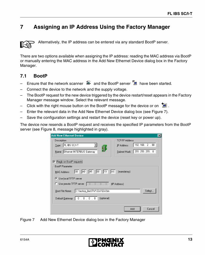
– Enter the relevant data in the Add New Ethernet Device dialog box (see Figure 7).
– Save the configuration settings and restart the device (reset key or power up).
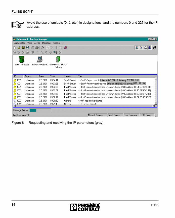
The device now resends a BootP request and receives the specified IP parameters from the BootP server (see Figure 8, message highlighted in gray).
Figure 7 Add New Ethernet Device dialog box in the Factory Manager
FL IBS SC/I-T
14 6154A
Avoid the use of umlauts (ö, ü, etc.) in designations, and the numbers 0 and 225 for the IP address.
Figure 8 Requesting and receiving the IP parameters (gray)

FL IBS SC/I-T
6154A 15
7.2 Manually Entering the MAC Address in the Add New Ethernet Device Dialog Box in the Factory Manager
– Open the Add New Ethernet Device dialog box (see Figure 9) by clicking on , by selecting "Add Device" from the Device View context menu or by using the Ctrl+A key combination.
– Enter the desired data under "Description" and "TCP/IP Address".
– Activate the "BootP Parameter" by selecting "Reply on BootP Requests".
– Enter the MAC address. It is displayed on the bottom right of the front plate and on the right-hand side of the rating plate.
– Save the configuration settings and restart the device (reset key or power up).
The device now sends another BootP request and receives the specified IP parameters from the BootP server (see Figure 8, message highlighted in gray).
Figure 9 Add New Ethernet Device dialog box in the Factory Manager
Avoid the use of umlauts (ö, ü, etc.) in designations, and the numbers 0 and 225 for the IP address.

FL IBS SC/I-T
16 6154A
8 Selecting IP Addresses
The IP address is a 32-bit address, which consists of a network part and a user part. The network part consists of the network class and the network address.There are currently five defined network classes; classes A, B, and C are used in modern applications, while classes D and E are hardly ever used. It is therefore usually sufficient if a network device only "recognizes" classes A, B, and C.
The network class is represented by the first bits for the binary representation of the IP address. The key factor is the number of "ones" before the first "zero". The assignment of classes is shown in the following table. The free cells in the table are not relevant to the network class and are used for the network address.
The bits for the network class are followed by those for the network address and the user address. Depending on the network class, a different number of bits are available, both for the network address (network ID) and the user address (host ID).
IP addresses can be represented in decimal, octal or hexadecimal form. In decimal form, bytes are separated by dots (dotted decimal notation) to show the logical grouping of the individual bytes.
The decimal points do not divide the address into a network and user address. Only the value of the first bits (before the first "zero") specifies the network class and the number of remaining bits in the address.
Bit 1 Bit 2 Bit 3 Bit 4 Bit 5
Class A 0
Class B 1 0
Class C 1 1 0
Class D 1 1 1 0
Class E 1 1 1 1 0
Network ID Host ID
Class A 7 bits 24 bits
Class B 14 bits 16 bits
Class C 21 bits 8 bits
Class D 28-bit multicast identifier
Class E 27 bits (reserved)
FL IBS SC/I-T
6154A 17
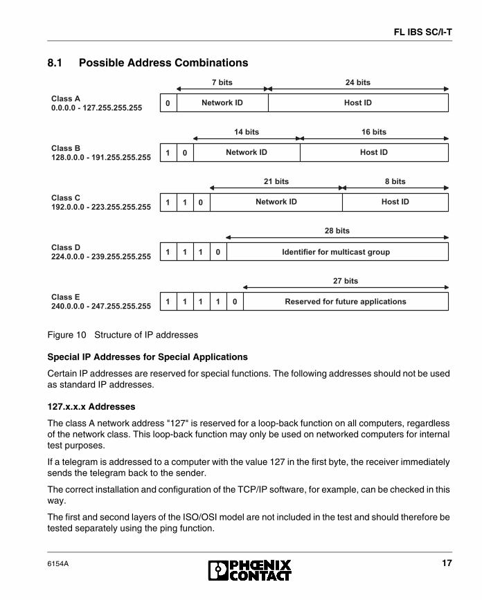
8.1 Possible Address Combinations
Figure 10 Structure of IP addresses
Special IP Addresses for Special Applications
Certain IP addresses are reserved for special functions. The following addresses should not be used as standard IP addresses.
127.x.x.x Addresses
The class A network address "127" is reserved for a loop-back function on all computers, regardless of the network class. This loop-back function may only be used on networked computers for internal test purposes.
If a telegram is addressed to a computer with the value 127 in the first byte, the receiver immediately sends the telegram back to the sender.
The correct installation and configuration of the TCP/IP software, for example, can be checked in this way.
The first and second layers of the ISO/OSI model are not included in the test and should therefore be tested separately using the ping function.
) � * � % � � � * � %
' � � * � % ' + � * � %
� ' � * � % , � * � %
� , � * � %
� ) � * � %
� � - � � . � / � 0 � % � / �
0 � % � / �
0 � % � / �
� � - � � . � / �
� � - � � . � / �
/ � � � � 1 � � � � 1 � � � 2 � � � � % � � � � � � �
" � % � � � � � � 1 � � � 1 � � � � � � � � � � � � � %
�
�
�
�
�
'
''
'''
''''
� � % % � 3� 4 � 4 � 4 � � ! � ' � ) 4 � $ $ 4 � $ $ 4 � $ $
� � % % � 5' � , 4 � 4 � 4 � � ! � ' 6 ' 4 � $ $ 4 � $ $ 4 � $ $
� � % % � �' 6 � 4 � 4 � 4 � � ! � � � 7 4 � $ $ 4 � $ $ 4 � $ $
� � % % � �� � � 4 � 4 � 4 � � ! � � 7 6 4 � $ $ 4 � $ $ 4 � $ $
� � % % � �� � � 4 � 4 � 4 � � ! � � � ) 4 � $ $ 4 � $ $ 4 � $ $
FL IBS SC/I-T
18 6154A
Value 255 in the Byte
Value 255 is defined as a broadcast address. The telegram is therefore sent to all the computers that are in the same part of the network. Examples include: 004.255.255.255, 198.2.7.255 or 255.255.255.255 (all the computers in all the networks). If the network is divided into subnetworks, the subnet masks must be observed during calculation, otherwise some devices may be omitted.
0.x.x.x Addresses
Value 0 is the ID of the specific network. If the IP address starts with a zero, the receiver is in the same network. Example: 0.2.1.1 refers to device 2.1.1 in this network.
The zero previously signified a broadcast address. If older devices are used, an unauthorized broadcast and the complete overload of the entire network (broadcast storm) may occur when using the IP address 0.x.x.x.
9 Subnet Masks
Routers and gateways divide large networks into subnetworks. The IP addresses for individual devices are assigned to specific subnetworks by the subnet mask. The network part of an IP address is not modified by the subnet mask. An extended IP address is generated from the user address and subnet mask. Because the masked subnetwork is only recognized by the local computer, all the other devices display this extended IP address as a standard IP address.
9.1 Structure of the Subnet Mask
The subnet mask always contains the same number of bits as an IP address. The subnet mask has the same number of bits (in the same position) set to "one", which is reflected in the IP address for the network class.
Example: An IP address from class A contains a 1-byte network address and a 3-byte PC address. Therefore, the first byte of the subnet mask may only contain "ones".
The remaining bits (three bytes) then contain the address of the subnetwork and the PC. The extended IP address is created when the bits for the IP address and the bits for the subnet mask are ANDed. Because the subnetwork is only recognized by local devices, the corresponding IP address appears as a "normal" IP address to all the other devices.

FL IBS SC/I-T
6154A 19
Application
If the ANDing of the address bits gives the local network address and the local subnetwork address, the device is located in the local network. If the ANDing gives a different result, the data telegram is sent to the subnetwork router.
Example for a class B subnet mask:
Using this subnet mask, the TCP/IP protocol software differentiates between the devices that are connected to the local subnetwork and the devices that are located in other subnetworks.
Example: Device 1 wants to establish a connection with device 2 using the above subnet mask. Device 2 has IP address 59.EA.55.32.
IP address display for device 2:
The individual subnet mask and the IP address for device 2 are then ANDed bit-by-bit by the software to determine whether device 2 is located in the local subnetwork.
ANDing the subnet mask and IP address for device 2:
After ANDing, the software determines that the relevant subnetwork (01) does not correspond to the local subnetwork (11) and the data telegram is transferred to a subnetwork router.
� � � � � � � � � ' � � �
� � � � � � � � � � � � � � � � � � � � � � � � � � � � � � � � � � � � � � �
. , ( / 0 � - � � / � , � - 1
� , - / � 2 � - � � / � , � - 1
� 3 4 - � � ( / 5 � 4 , � � 0 / � �
� ' � % # � � � � ! �
� � � � � � � � � � � � � � � � � � � � � � � � � � � � � � � � � � � � � � �
6 7 / � . , ( / 0 � - � � / � , � - 1
� , - / � 2 � - � � / � , � - 1
� � � � � � � � � � � � � � � � � � � � � � � � � � � � � � � � � � � � � � �
� � � � � � � � � � � � � � � � � � � � � � � � � � � � � � � � � � � � � � �
� � � � � � � � � � � � � � � � � � � � � � � � � � � � � � � � � � � � � � �
� 3 4 - � � ( / 5 1
� $ � / � � � 1
� 3 0 � � / 8 � � � # � , - 9 1
# �
� 3 4 - �
FL IBS SC/I-T
20 6154A
10 Web-Based Management
The FL IBS SC/I-T has a web server, which generates the required pages for web-based management and, depending on the requirements of the user, sends them to the "Factory Manager" or a standard web browser.Web-based management can be used to access static information (e.g., technical data, MAC address) or dynamic information (e.g., IP address, status information) or to change the configuration (password-protected).
10.1 Calling Web-Based Management (WBM)
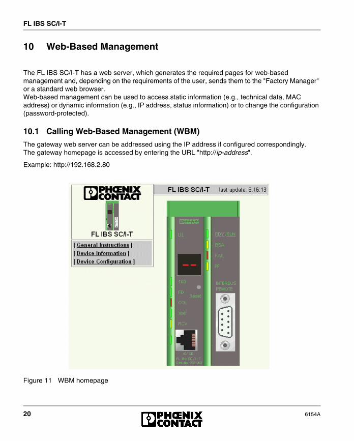
The gateway web server can be addressed using the IP address if configured correspondingly. The gateway homepage is accessed by entering the URL "http://ip-address".
Example: http://192.168.2.80
Figure 11 WBM homepage

FL IBS SC/I-T
6154A 21
10.2 Structure of the Web Pages
The gateway pages are divided into two, with the selection menu and the relevant submenus on the left-hand side, and the corresponding information displayed on the right-hand side. Static and dynamic information about the gateway can be found in the following menus.
10.3 Layout of the Web Pages
10.4 Password Protection
All Ethernet configuration changes on the gateway can only be made once a password has been entered. The factory set password is "private" (note the upper/lower case letters). The password can be changed at any time. Your unique password must be between four and twelve characters long.
If you forget the password, the device can be re-enabled by Phoenix Contact. Ensure you have the exact device designation and serial number ready when you contact the telephone number indicated on the last page.
� � � � � � � / � % � � � � � � %
� � � � � � � / � 1 � � 2 � � �
� � � � � � � � � � 1 � � � � � � �
� - 8 � � ( / � , � -
: - � / 0� . ; - , . / 0 � / � /6 / � � < / � � � - � / 0 0 / � , � -� � . / 0 � , / 9 - � � , .
� $ � � � - 8 , 9 3 � / � , � -� � � $ � � � - 8 , 9 3 � / � , � -� � 8 � < / � � � = � / � � ; / - 9 � $ / < � � �
� � � � � � � &

FL IBS SC/I-T
22 6154A
11 Firmware Update
When activating a firmware update, ensure that a valid firmware version is available. Otherwise the module attempts to update repeatedly.
11.1 Firmware Update Using The Factory Manager
The following steps must be carried out when executing a firmware update with the Factory Manager:
1. In Device View, right click on the device whose firmware you want to update. Select "Properties" from the context menu and then the "BootP Parameter" tab.
2. Select the "Reply on BootP requests" check box.
3. Local tftp server: Check that a valid firmware version is located in the "Download" directory of the Factory Manager. The firmware update cannot be executed from another directory. If the default settings have been used for the Factory Manager, the path leads to the following directory: "C:\Programs\Phoenix Contact\Factory Manager\Download".Remote tftp server: Make the firmware available to the server.
Figure 12 Ethernet Device Properties dialog box in the Factory Manager
FL IBS SC/I-T
6154A 23
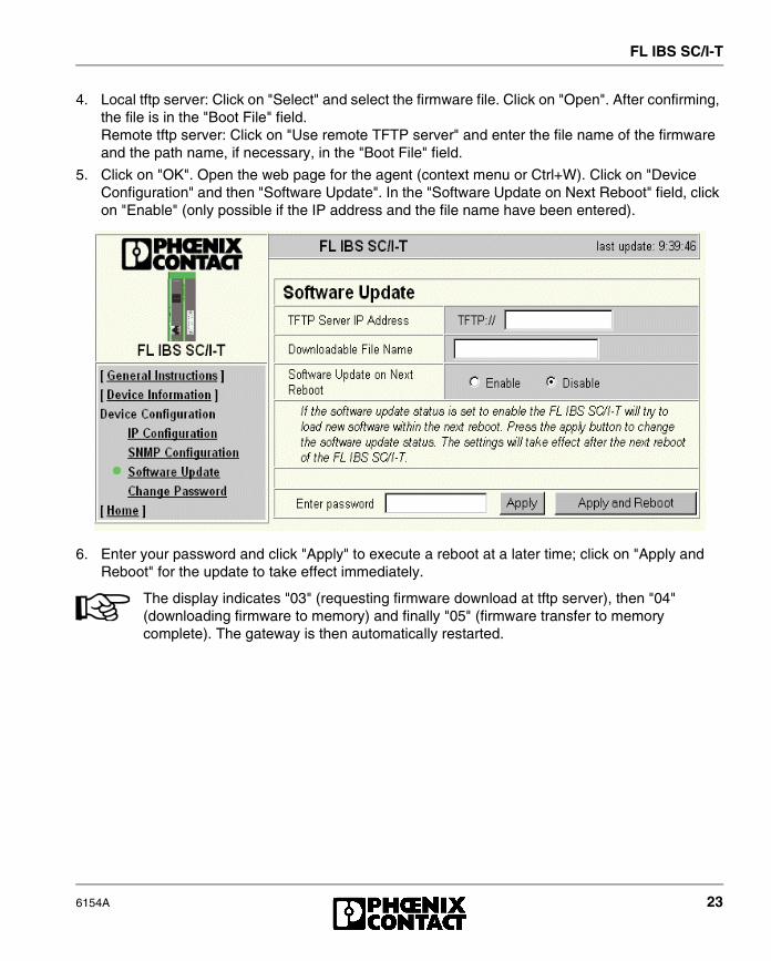
4. Local tftp server: Click on "Select" and select the firmware file. Click on "Open". After confirming, the file is in the "Boot File" field.Remote tftp server: Click on "Use remote TFTP server" and enter the file name of the firmware and the path name, if necessary, in the "Boot File" field.
5. Click on "OK". Open the web page for the agent (context menu or Ctrl+W). Click on "Device Configuration" and then "Software Update". In the "Software Update on Next Reboot" field, click on "Enable" (only possible if the IP address and the file name have been entered).
6. Enter your password and click "Apply" to execute a reboot at a later time; click on "Apply and Reboot" for the update to take effect immediately.
The display indicates "03" (requesting firmware download at tftp server), then "04" (downloading firmware to memory) and finally "05" (firmware transfer to memory complete). The gateway is then automatically restarted.
FL IBS SC/I-T
24 6154A
11.2 Firmware Update Using Web-Based Management (WBM) Without the Factory Manager
The following steps must be carried out when executing a firmware update with WBM:
1. Open the web page for the gateway, by entering the IP address for the agent in the address line of a standard web browser. After the web page has been loaded, click on "Device Configuration" and then "Software Update". Enter the IP address of the tftp server in the "TFTP Server IP Address" field. Then enter the file name of the firmware and the path name, if necessary, in "Downloadable File Name". In the "Software Update on Next Reboot" field, click on "Enable".
2. Enter your password and click "Apply" to execute a reboot at a later time; click on "Apply and Reboot" for the update to take effect immediately.
If a BootP-Server is active in the network, it can overwrite the settings made on the gateway web page.
The display indicates "03" (requesting firmware download at tftp server), then "04" (downloading firmware to memory) and finally "05" (firmware transfer to memory complete). The gateway is then automatically restarted.
FL IBS SC/I-T
6154A 25
12 Ethernet Communication
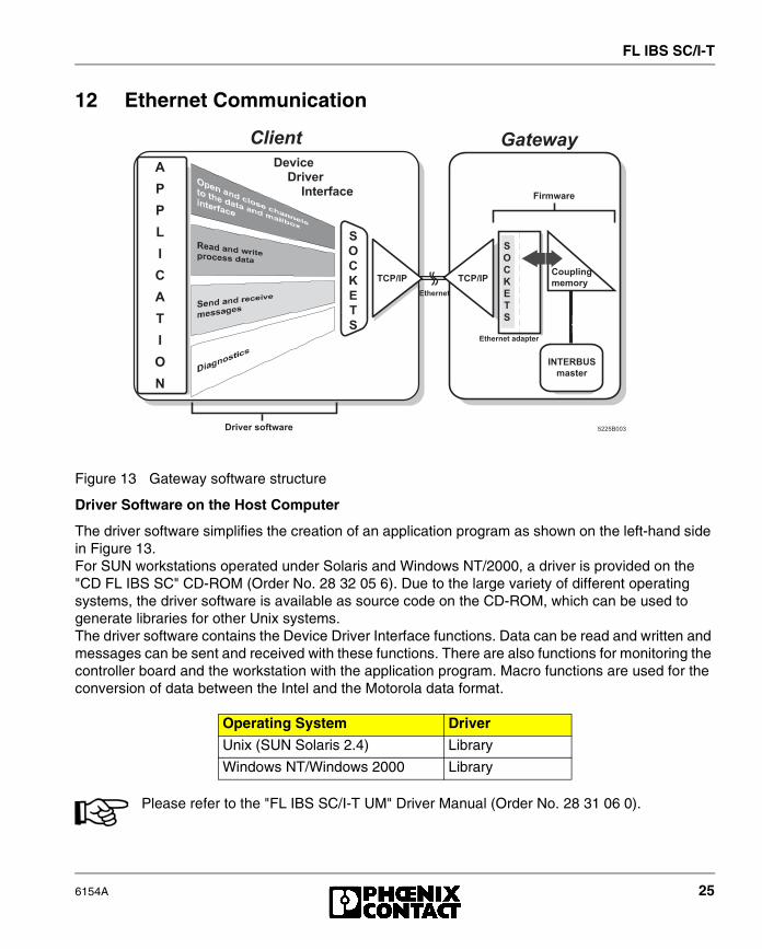
Figure 13 Gateway software structure
Driver Software on the Host Computer
The driver software simplifies the creation of an application program as shown on the left-hand side in Figure 13. For SUN workstations operated under Solaris and Windows NT/2000, a driver is provided on the "CD FL IBS SC" CD-ROM (Order No. 28 32 05 6). Due to the large variety of different operating systems, the driver software is available as source code on the CD-ROM, which can be used to generate libraries for other Unix systems.The driver software contains the Device Driver Interface functions. Data can be read and written and messages can be sent and received with these functions. There are also functions for monitoring the controller board and the workstation with the application program. Macro functions are used for the conversion of data between the Intel and the Motorola data format.
Please refer to the "FL IBS SC/I-T UM" Driver Manual (Order No. 28 31 06 0).
Operating System Driver
Unix (SUN Solaris 2.4) Library
Windows NT/Windows 2000 Library
� � � � � � � � � � �
3
8
8
9
/
�
3
/
&
�
�
&
�
:
�
�
� 8 ; / 8
� � � � � �� � � � � � � � � �� � � � � � � � / � � � 1 � �
� 8 ; / 8
� � � � � �
�
&
�
:
�
�
� � � � � � � � � � �
� � � � � � � �
2 � 2 � � �
/ � � " 5 < �
2 % � �
� � � 2 - � �
� � � � � � � % � 1 - � � � � � � � � � !

FL IBS SC/I-T
26 6154A
Ethernet Communication Functions of the Ethernet/INTERBUS Gateway
The gateway provides an easy means of Ethernet communication. It encodes and decodes the data telegrams. It also ensures the network-specific addressing of the controller board in the network, i.e., the management of the IP address.
Host Monitoring
Host monitoring can be used to determine whether there is still a connection between the bus terminal (host) and the client (user workstation) and whether the client responds to requests. With this monitoring it is also possible to detect the following error causes:
– Cable broken or not connected
– Transceiver faulty
– Errors or faults in the Ethernet adapter of the gateway or in the client
– System crash of the client
– Error in the TCP/IP protocol stack
This status monitoring can be activated for all clients with a DDI connection. A connection to a client, which only uses the Ethernet management cannot be monitored.
When host monitoring is activated, output data is reset if an error occurs in the network line.

FL IBS SC/I-T
6154A 27
Supported DDI Functions
Service Function
DDI_DevOpenNode Establishes connection to the device
DDI_DevCloseNode Aborts connection to the device
DDI_DTI_ReadData Reads process data
DDI_DTI_WriteData Writes process data
DDI_DTI_ReadWriteData Reads and writes process data in one call
DDI_MXI_SndMessage Sends a message
DDI_MXI_RcvMessage Reads a message
GetIBSDiagnosticReads the diagnostic bit register and the diagnostic parameter register
DDI_GetSysFailRegister Reads the DPM status SysFail register
ETH_SetHostChecking Activates client monitoring
ETH_ClearHostChecking Deactivates client monitoring
ETH_SetDTITimeoutCtrl Monitors the DTI data channel
ETH_ClearDTITimeoutCtrl Deactivates monitoring of the DTI data channel
ETH_SetNetFail Activates the SysFail signal
ETH_GetNetFailStatus Requests SysFail status
ETH_ClrNetFailStatus Resets SysFail status
ETH_SetNetFailMode Changes the behavior of the gateway in the event of a net fail
ETH_GetNetFailMode Reads the NetFail mode
ETH_InitiateManagement Establishes a management connection to the gateway
ETH_AbortManagement Terminates a management connection
ETH_HardwareReset Triggers a complete hardware reset
ETH_EnableHardwareReset Enables the hardware reset commandusing TCP/IP
ETH_DisableHardwareResetDisables the hardware resetusing TCP/IP
Notification Mode 1 Operating mode for more effective reading of messages
Notification Mode 2 Operating mode for more effective reading of messages
FL IBS SC/I-T
28 6154A
13 Trap Generation
When important events occur, e.g., a configuration change, the gateway sends a trap to a trap receiver defined by the user. This enables the network administrator to react quickly to these events and to ensure network availability. Traps take priority and are thus the first to be transmitted into the network. Traps are usually only transmitted once. The exception is the hardware configuration trap, which is generated if a change to the configuration has not (yet) been saved.
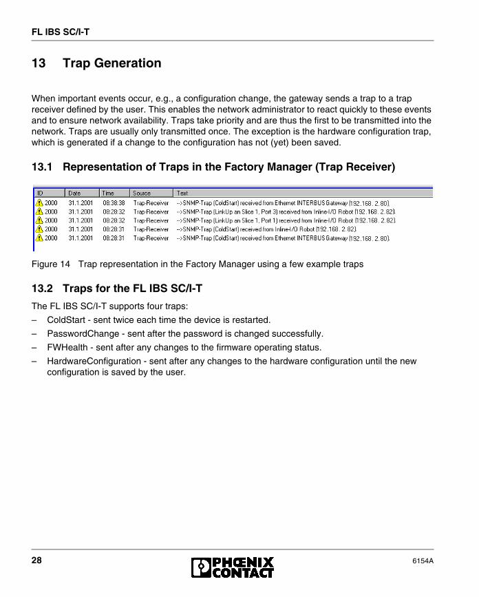
13.1 Representation of Traps in the Factory Manager (Trap Receiver)
Figure 14 Trap representation in the Factory Manager using a few example traps
13.2 Traps for the FL IBS SC/I-T
The FL IBS SC/I-T supports four traps:
– ColdStart - sent twice each time the device is restarted.
– PasswordChange - sent after the password is changed successfully.
– FWHealth - sent after any changes to the firmware operating status.
– HardwareConfiguration - sent after any changes to the hardware configuration until the new configuration is saved by the user.
FL IBS SC/I-T
6154A 29
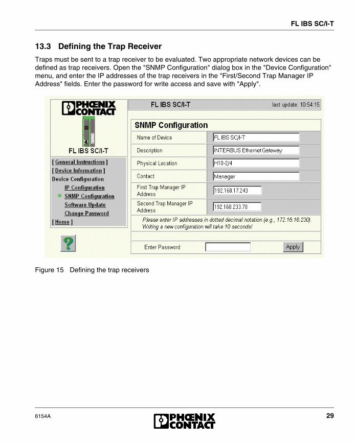
13.3 Defining the Trap Receiver
Traps must be sent to a trap receiver to be evaluated. Two appropriate network devices can be defined as trap receivers. Open the "SNMP Configuration" dialog box in the "Device Configuration" menu, and enter the IP addresses of the trap receivers in the "First/Second Trap Manager IP Address" fields. Enter the password for write access and save with "Apply".
Figure 15 Defining the trap receivers
FL IBS SC/I-T
30 6154A
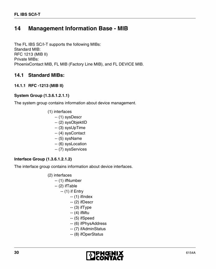
14 Management Information Base - MIB
The FL IBS SC/I-T supports the following MIBs:Standard MIB:RFC 1213 (MIB II) Private MIBs:PhoenixContact MIB, FL MIB (Factory Line MIB), and FL DEVICE MIB.
14.1 Standard MIBs:
14.1.1 RFC -1213 (MIB II)
System Group (1.3.6.1.2.1.1)
The system group contains information about device management.
Interface Group (1.3.6.1.2.1.2)
The interface group contains information about device interfaces.
(1) interfaces-- (1) sysDescr-- (2) sysObjektID-- (3) sysUpTime-- (4) sysContact-- (5) sysName-- (6) sysLocation-- (7) sysServices
(2) interfaces-- (1) ifNumber-- (2) ifTable
-- (1) if Entry-- (1) ifIndex-- (2) ifDescr-- (3) ifType-- (4) ifMtu-- (5) ifSpeed-- (6) ifPhysAddress-- (7) ifAdminStatus-- (8) ifOperStatus

FL IBS SC/I-T
6154A 31
Address Translation Group - AT (1.3.6.1.2.1.3)
The address translation group is mandatory for all systems. It contains information about the address assignment.
Internet Protocol Group - IP (1.3.6.1.2.1.4)
The Internet protocol group is mandatory for all systems. It contains information concerning IP switching.
-- (9) ifLastChange-- (10) ifInOctets-- (11) ifInUcastPkts-- (12) ifInNUcastPkts-- (13) ifInDiscards-- (14) ifInErrors-- (15) ifInUnknownProtos-- (16) ifOutOctets-- (17) ifOutUcastPkts-- (18) ifOutNUcastPkts-- (19) ifOutDiscards-- (20) ifOutErrors-- (21) ifOutQLen-- (22) ifSpecific
(3) at-- (1) atTable
-- (1) atEntry-- (1) atIfIndex-- (2) atPhysAddress-- (3) atNetAddress
(4) ip-- (1) ipForwarding-- (2) ipDefaultTTL-- (3) ipInReceives-- (4) ipInHdrErrors-- (5) ipInAddrErrors-- (6) ipForwDatagrams-- (7) ipInUnknownProtos-- (8) ipInDiscards-- (9) ipInDelivers
FL IBS SC/I-T
32 6154A
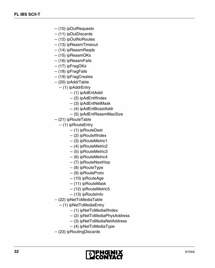
-- (10) ipOutRequests-- (11) ipOutDiscards-- (12) ipOutNoRoutes-- (13) ipReasmTimeout-- (14) ipReasmReqds-- (15) ipReasmOKs-- (16) ipReasmFails-- (17) ipFragOKs-- (18) ipFragFails-- (19) ipFragCreates-- (20) ipAddrTable
-- (1) ipAddrEntry-- (1) ipAdEntAddr-- (2) ipAdEntIfIndex-- (3) ipAdEntNetMask-- (4) ipAdEntBcastAddr-- (5) ipAdEntReasmMaxSize
-- (21) ipRouteTable-- (1) ipRouteEntry
-- (1) ipRouteDest-- (2) ipRouteIfIndex-- (3) ipRouteMetric1-- (4) ipRouteMetric2-- (5) ipRouteMetric3-- (6) ipRouteMetric4-- (7) ipRouteNextHop-- (8) ipRouteType-- (9) ipRouteProto-- (10) ipRouteAge-- (11) ipRouteMask-- (12) ipRouteMetric5-- (13) ipRouteInfo
-- (22) ipNetToMediaTable-- (1) ipNetToMediaEntry
-- (1) ipNetToMediaIfIndex-- (2) ipNetToMediaPhysAddress-- (3) ipNetToMediaNetAddress-- (4) ipNetToMediaType
-- (23) ipRoutingDiscards

FL IBS SC/I-T
6154A 33
ICMP Group (1.3.6.1.2.1.5)
The Internet control message protocol group has mandatory characters for all systems. It contains information about error treatment and control in Internet data traffic.
(5) icmp-- (1) icmpInMsgs-- (2) icmpInErrors-- (3) icmpInDestUnreachs-- (4) icmpInTimeExcds-- (5) icmpInParmProbs-- (6) icmpInSrcQuenchs-- (7) icmpInRedirects-- (8) icmpInEchos-- (9) icmpInEchoReps-- (10) icmpInTimestamps-- (11) icmpInTimestampReps-- (12) icmpInAddrMasks-- (13) icmpInAddrMaskReps-- (14) icmpOutMsgs-- (15) icmpOutErrors-- (16) icmpOutDestUnreachs-- (17) icmpOutTimeExcds-- (18) icmpOutParmProbs-- (19) icmpOutSrcQuenchs-- (20) icmpOutRedirects-- (21) icmpOutEchos-- (22) icmpOutEchoReps-- (23) icmpOutTimestamps-- (24) icmpOutTimestampReps-- (25) icmpOutAddrMasks-- (26) icmpOutAddrMaskReps
FL IBS SC/I-T
34 6154A
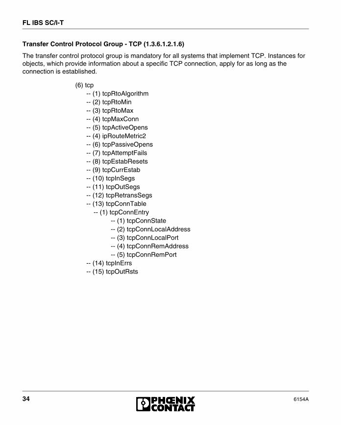
Transfer Control Protocol Group - TCP (1.3.6.1.2.1.6)
The transfer control protocol group is mandatory for all systems that implement TCP. Instances for objects, which provide information about a specific TCP connection, apply for as long as the connection is established.
(6) tcp-- (1) tcpRtoAlgorithm-- (2) tcpRtoMin-- (3) tcpRtoMax-- (4) tcpMaxConn-- (5) tcpActiveOpens-- (4) ipRouteMetric2-- (6) tcpPassiveOpens-- (7) tcpAttemptFails-- (8) tcpEstabResets-- (9) tcpCurrEstab-- (10) tcpInSegs-- (11) tcpOutSegs-- (12) tcpRetransSegs-- (13) tcpConnTable
-- (1) tcpConnEntry-- (1) tcpConnState-- (2) tcpConnLocalAddress-- (3) tcpConnLocalPort-- (4) tcpConnRemAddress-- (5) tcpConnRemPort
-- (14) tcpInErrs-- (15) tcpOutRsts
FL IBS SC/I-T
6154A 35
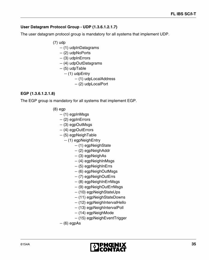
User Datagram Protocol Group - UDP (1.3.6.1.2.1.7)
The user datagram protocol group is mandatory for all systems that implement UDP.
EGP (1.3.6.1.2.1.8)
The EGP group is mandatory for all systems that implement EGP.
(7) udp-- (1) udpInDatagrams-- (2) udpNoPorts-- (3) udpInErrors-- (4) udpOutDatagrams-- (5) udpTable
-- (1) udpEntry-- (1) udpLocalAddress-- (2) udpLocalPort
(8) egp-- (1) egpInMsgs-- (2) egpInErrors-- (3) egpOutMsgs-- (4) egpOutErrors-- (5) egpNeighTable
-- (1) egpNeighEntry-- (1) egpNeighState-- (2) egpNeighAddr-- (3) egpNeighAs-- (4) egpNeighInMsgs-- (5) egpNeighInErrs-- (6) egpNeighOutMsgs-- (7) egpNeighOutErrs-- (8) egpNeighInErrMsgs-- (9) egpNeighOutErrMsgs-- (10) egpNeighStateUps-- (11) egpNeighStateDowns-- (12) egpNeighIntervalHello-- (13) egpNeighIntervalPoll-- (14) egpNeighMode-- (15) egpNeighEventTrigger
-- (6) egpAs

FL IBS SC/I-T
36 6154A
Simple Network Management Protocol Group (1.3.6.1.2.1.11)
The simple network management protocol group is mandatory for all systems. In SNMP devices, which are optimized to support either a single agent or a single management station, some of the listed objects will be overwritten with the value "0".
(11) snmp-- (1) snmpInPkts-- (2) snmpOutPkts-- (3) snmpInBadVersions-- (4) snmpInBadCommunityNames-- (5) snmpInBadCommunityUses-- (6) snmpInASNParseErrs-- (7) not used-- (8) snmpInTooBigs-- (9) snmpInNoSuchNames-- (10) snmpInBadValues-- (11) snmpInReadOnlys-- (12) snmpInGenErrs-- (13) snmpInTotalReqVars-- (14) snmpInTotalSetVars-- (15) snmpInGetRequests-- (16) snmpInGetNexts-- (17) snmpInSetRequests-- (18) snmpInGetResponses-- (19) snmpInTraps-- (20) snmpOutTooBigs-- (21) snmpOutNoSuchNames-- (22) snmpOutBadValues-- (23) not used-- (24) snmpOutGenErrs-- (25) snmpOutGetRequests-- (26) snmpOutGetNexts-- (27) snmpOutSetRequests-- (28) snmpOutGetResponses-- (29) snmpOutTraps-- (30) snmpEnableAuthenTraps
FL IBS SC/I-T
6154A 37
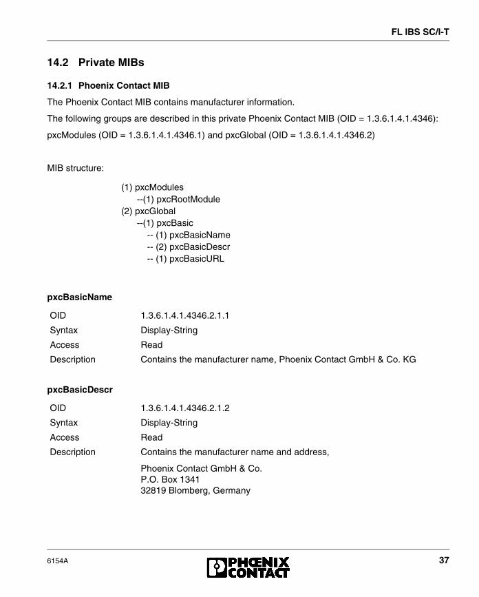
14.2 Private MIBs
14.2.1 Phoenix Contact MIB
The Phoenix Contact MIB contains manufacturer information.
The following groups are described in this private Phoenix Contact MIB (OID = 1.3.6.1.4.1.4346):
pxcModules (OID = 1.3.6.1.4.1.4346.1) and pxcGlobal (OID = 1.3.6.1.4.1.4346.2)
MIB structure:
pxcBasicName
pxcBasicDescr
(1) pxcModules--(1) pxcRootModule
(2) pxcGlobal--(1) pxcBasic
-- (1) pxcBasicName-- (2) pxcBasicDescr-- (1) pxcBasicURL
OID 1.3.6.1.4.1.4346.2.1.1
Syntax Display-String
Access Read
Description Contains the manufacturer name, Phoenix Contact GmbH & Co. KG
OID 1.3.6.1.4.1.4346.2.1.2
Syntax Display-String
Access Read
Description Contains the manufacturer name and address,
Phoenix Contact GmbH & Co.P.O. Box 134132819 Blomberg, Germany

FL IBS SC/I-T
38 6154A
pxcBasicURL
14.2.2 FL MIB
The FL MIB contains information about the Factory Line product group.
This private FL MIB (OID = 1.3.6.1.4.1.4346) describes the
pxcFactoryLine (OID = 1.3.6.1.4.1.4346.11) group.
MIB structure:
OID 1.3.6.1.4.1.4346.2.1.3
Syntax Display-String
Access Read
Description Contains the URL for the manufacturer,
http://www.phoenixcontact.com
(1) pxcModules--(2) pxcFLModule
(11) pxcFactoryLine--(1) flGlobal
-- (1) flBasic-- (1) flBasicName-- (2) flBasicDescr-- (3) flBasicURL-- (4) flBasicCompCapacity
-- (2) flComponents-- (1) flComponentsTable
-- (1) flComponentsEntry-- (1) flComponentsIndex-- (2) flComponentsName-- (3) flComponentsDescr-- (1) flComponentsURL-- (1) flComponentsOrderNumber

FL IBS SC/I-T
6154A 39
flBasicName
flBasicDescr
flBasicURL
flBasicCompCapacity
OID 1.3.6.1.4.1.4346.11.1.1.1
Syntax Display-String
Access Read
Description Contains the name of the product group,
Factory Line
OID 1.3.6.1.4.1.4346.11.1.1.2
Syntax Display-String
Access Read
Description Contains a brief description of the product group,
Ethernet installation system
OID 1.3.6.1.4.1.4346.11.1.1.3
Syntax Display-String
Access Read
Description Contains a URL for the product group,
http://www.factoryline.de
OID 1.3.6.1.4.1.4346.11.1.1.4
Syntax Integer32 (1...1024)
Access Read
Description Contains the number of Factory Line devices that can be managed in this device unit
FL IBS SC/I-T
40 6154A
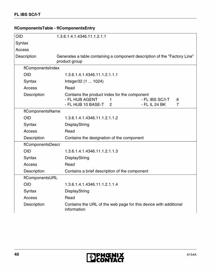
flComponentsTable - flComponentsEntry
OID 1.3.6.1.4.1.4346.11.1.2.1.1
Syntax
Access
Description Generates a table containing a component description of the "Factory Line" product group
flComponentsIndex
OID 1.3.6.1.4.1.4346.11.1.2.1.1.1
Syntax Integer32 (1 ... 1024)
Access Read
Description Contains the product index for the component- FL HUB AGENT 1 - FL IBS SC/I-T 6- FL HUB 10 BASE-T 2 - FL IL 24 BK 7
flComponentsName
OID 1.3.6.1.4.1.4346.11.1.2.1.1.2
Syntax DisplayString
Access Read
Description Contains the designation of the component
flComponentsDescr
OID 1.3.6.1.4.1.4346.11.1.2.1.1.3
Syntax DisplayString
Access Read
Description Contains a brief description of the component
flComponentsURL
OID 1.3.6.1.4.1.4346.11.1.2.1.1.4
Syntax DisplayString
Access Read
Description Contains the URL of the web page for this device with additionalinformation

FL IBS SC/I-T
6154A 41
flComponentsOrderNumber
OID 1.3.6.1.4.1.4346.11.1.2.1.1.5
Syntax DisplayString
Access Read
Description Contains the order number of the component
FL IBS SC/I-T
42 6154A
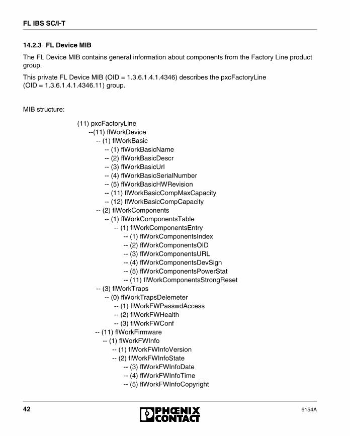
14.2.3 FL Device MIB
The FL Device MIB contains general information about components from the Factory Line product group.
This private FL Device MIB (OID = 1.3.6.1.4.1.4346) describes the pxcFactoryLine (OID = 1.3.6.1.4.1.4346.11) group.
MIB structure:
(11) pxcFactoryLine--(11) flWorkDevice
-- (1) flWorkBasic-- (1) flWorkBasicName-- (2) flWorkBasicDescr-- (3) flWorkBasicUrl-- (4) flWorkBasicSerialNumber-- (5) flWorkBasicHWRevision-- (11) flWorkBasicCompMaxCapacity-- (12) flWorkBasicCompCapacity
-- (2) flWorkComponents-- (1) flWorkComponentsTable
-- (1) flWorkComponentsEntry-- (1) flWorkComponentsIndex-- (2) flWorkComponentsOID-- (3) flWorkComponentsURL-- (4) flWorkComponentsDevSign-- (5) flWorkComponentsPowerStat-- (11) flWorkComponentsStrongReset
-- (3) flWorkTraps-- (0) flWorkTrapsDelemeter
-- (1) flWorkFWPasswdAccess-- (2) flWorkFWHealth-- (3) flWorkFWConf
-- (11) flWorkFirmware-- (1) flWorkFWInfo
-- (1) flWorkFWInfoVersion-- (2) flWorkFWInfoState
-- (3) flWorkFWInfoDate-- (4) flWorkFWInfoTime-- (5) flWorkFWInfoCopyright

FL IBS SC/I-T
6154A 43
flWorkBasicName
-- (6) flWorkFWInfoBootVersion-- (7) flWorkFWInfoBootState-- (8) flWorkFWInfoBootDate-- (9) flWorkFWInfoBootTime-- (11) flWorkFWInfoOperStatus-- (12) flWorkFWInfoHealthText
-- (2) flWorkFWCtrl-- (1) flWorkFWCtrlBasic
-- (1) flWorkFWCtrlReset-- (2) flWorkFWCtrlTrapDestCapacity
-- (2) flWorkFWCtrlTrapDest-- (1) flWorkFWCtrlTrapDestTable
-- (1) flWorkFWCtrlTrapDestEntry-- (1) flWorkFWCtrlTrapDestIndex-- (2) flWorkFWCtrlTrapDestIPAddr
-- (3) flWorkFWCtrlPasswd-- (1) flWorkFWCtrlPasswdSet-- (2) flWorkFWCtrlPasswdSuccess
-- (4) flWorkFWCtrlUpdate-- (1) flWorkFWCtrlUpdateEnable-- (2) flWorkFWCtrlTftpIPAddr-- (3) flWorkFWCtrlTftpFile
-- (5) flWorkFWCtrlConf-- (1) flWorkFWCtrlConfStatus
-- (11) flWorkFWInfo-- (1) flWorkFWParamSaveConfig
OID 1.3.6.1.4.1.4346.11.11.1.1
Syntax DisplayString
Access Read/write
Description Contains the device name

FL IBS SC/I-T
44 6154A
flWorkBasicDescr
flWorkBasicName
flWorkBasicSerialNumber
flWorkBasicHWRevision
flWorkBasicCompMaxCapacity
OID 1.3.6.1.4.1.4346.11.11.1.2
Syntax DisplayString
Access Read/write
Description Contains a brief description
OID 1.3.6.1.4.1.4346.11.11.1.3
Syntax DisplayString
Access Read
Description Contains the URL of the device web page
OID 1.3.6.1.4.1.4346.11.11.1.4
Syntax Octet String (12)
Access Read
Description Contains the serial number of the device
OID 1.3.6.1.4.1.4346.11.11.1.5
Syntax Octet String (4)
Access Read
Description Contains the hardware version of the device
OID 1.3.6.1.4.1.4346.11.11.1.11
Syntax Integer32 (1...1024)
Access Read
Description Contains the maximum possible number of devices that can be managed in conjunction with the gateway

FL IBS SC/I-T
6154A 45
flWorkBasicCompCapacity
flWorkComponentsTable - flWorkComponentsEntry
OID 1.3.6.1.4.1.4346.11.11.1.12
Syntax Integer32 (1...1024)
Access Read
Description Contains the actual number of connected devices that can be managed
OID 1.3.6.1.4.1.4346.11.11.2.1.1
Syntax
Access
Description Generates a table with the description of individual components
flWorkComponentsIndex
OID 1.3.6.1.4.1.4346.11.1.2.1.1.1
Syntax Integer32 (1 ... 1024)
Access Read
Description Contains the index for the component
flWorkComponentsOID
OID 1.3.6.1.4.1.4346.11.1.2.1.1.2
Syntax OBJECT IDENTIFIER
Access Read
Description Contains the designation of OIDs/complete path entries
flComponentsURL
OID 1.3.6.1.4.1.4346.11.1.2.1.1.3
Syntax DisplayString
Access Read
Description Contains the URL of the web page for this component with additionalinformation
flWorkComponentsDevSign
OID 1.3.6.1.4.1.4346.11.11.2.1.1.4
Syntax INTEGER (0 ... 255)
Access Read
Description Contains the index entry for the component

FL IBS SC/I-T
46 6154A
flWorkFWPasswdAccess
flWorkFWHealth
flWorkComponentsPowerStat
OID 1.3.6.1.4.1.4346.11.11.2.1.1.5
Syntax INTEGER
Access Read
Description Contains status information about the connected supplyvoltages:- Unknown 1- No voltage available 2- Supply voltage 1 OK 3- Supply voltage 2 OK 4- Supply voltage 1 and 2 OK 5
flWorkComponentsStrongReset
OID 1.3.6.1.4.1.4346.11.11.2.1.1.11
Syntax INTEGER
Access Read/write
Description With write access, a reset can be executed with "2". With read access, the value is always "1" - no reset.
OID 1.3.6.1.4.1.4346.11.11.3.0.1
Syntax
Access
Description PasswordChange - sent after the password is changed successfully.
OID 1.3.6.1.4.1.4346.11.11.3.0.2
Syntax
Access
Description FWHealth - sent after any changes to the firmware operating status.
FL IBS SC/I-T
6154A 47
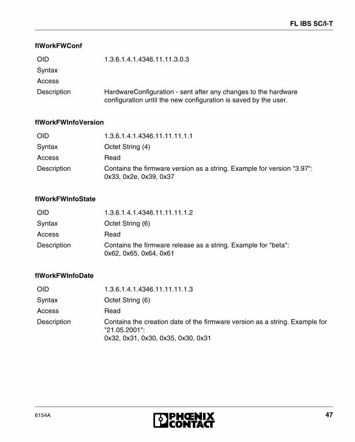
flWorkFWConf
flWorkFWInfoVersion
flWorkFWInfoState
flWorkFWInfoDate
OID 1.3.6.1.4.1.4346.11.11.3.0.3
Syntax
Access
Description HardwareConfiguration - sent after any changes to the hardware configuration until the new configuration is saved by the user.
OID 1.3.6.1.4.1.4346.11.11.11.1.1
Syntax Octet String (4)
Access Read
Description Contains the firmware version as a string. Example for version "3.97":0x33, 0x2e, 0x39, 0x37
OID 1.3.6.1.4.1.4346.11.11.11.1.2
Syntax Octet String (6)
Access Read
Description Contains the firmware release as a string. Example for "beta":0x62, 0x65, 0x64, 0x61
OID 1.3.6.1.4.1.4346.11.11.11.1.3
Syntax Octet String (6)
Access Read
Description Contains the creation date of the firmware version as a string. Example for "21.05.2001":0x32, 0x31, 0x30, 0x35, 0x30, 0x31
FL IBS SC/I-T
48 6154A
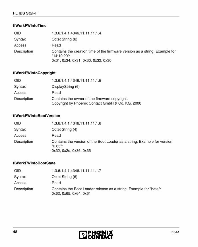
flWorkFWInfoTime
flWorkFWInfoCopyright
flWorkFWInfoBootVersion
flWorkFWInfoBootState
OID 1.3.6.1.4.1.4346.11.11.11.1.4
Syntax Octet String (6)
Access Read
Description Contains the creation time of the firmware version as a string. Example for "14:10:20":0x31, 0x34, 0x31, 0x30, 0x32, 0x30
OID 1.3.6.1.4.1.4346.11.11.11.1.5
Syntax DisplayString (6)
Access Read
Description Contains the owner of the firmware copyright.Copyright by Phoenix Contact GmbH & Co. KG, 2000
OID 1.3.6.1.4.1.4346.11.11.11.1.6
Syntax Octet String (4)
Access Read
Description Contains the version of the Boot Loader as a string. Example for version "2.65":0x32, 0x2e, 0x36, 0x35
OID 1.3.6.1.4.1.4346.11.11.11.1.7
Syntax Octet String (6)
Access Read
Description Contains the Boot Loader release as a string. Example for "beta":0x62, 0x65, 0x64, 0x61
FL IBS SC/I-T
6154A 49
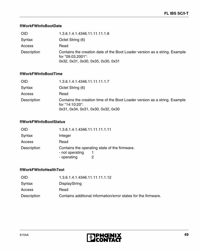
flWorkFWInfoBootDate
flWorkFWInfoBootTime
flWorkFWInfoBootStatus
flWorkFWInfoHealthText
OID 1.3.6.1.4.1.4346.11.11.11.1.8
Syntax Octet String (6)
Access Read
Description Contains the creation date of the Boot Loader version as a string. Example for "09.03.2001":0x32, 0x31, 0x30, 0x35, 0x30, 0x31
OID 1.3.6.1.4.1.4346.11.11.11.1.7
Syntax Octet String (6)
Access Read
Description Contains the creation time of the Boot Loader version as a string. Example for "14:10:20":0x31, 0x34, 0x31, 0x30, 0x32, 0x30
OID 1.3.6.1.4.1.4346.11.11.11.1.11
Syntax Integer
Access Read
Description Contains the operating state of the firmware.- not operating 1- operating 2
OID 1.3.6.1.4.1.4346.11.11.11.1.12
Syntax DisplayString
Access Read
Description Contains additional information/error states for the firmware.

FL IBS SC/I-T
50 6154A
flWorkFWCtrlReset
flWorkFWCtrlTrapDestCapacity
flWorkFWCtrlTrapDestTable - flWorkFWCtrlTrapDestEntry
OID 1.3.6.1.4.1.4346.11.11.11.2.1.1
Syntax Integer
Access Read/write
Description With write access, a reset can be executed with "2".With read access, the value is always "1".
OID 1.3.6.1.4.1.4346.11.11.11.2.1.2
Syntax Integer32 (1 ... 1024)
Access Read
Description Contains the number of devices to which the traps are sent.
OID 1.3.6.1.4.1.4346.11.11.11.2.2.1.1
Syntax
Access
Description Generates a table containing information about individual components
flWorkFWCtrlTrapDestIndex
OID 1.3.6.1.4.1.4346.11.11.11.2.2.1.1.1
Syntax Integer32 (1 ... 1024)
Access Read
Description Contains the index of the target component, which should receive the traps
flWorkFWCtrlTrapDestIPAddr
OID 1.3.6.1.4.1.4346.11.1.2.1.1.2
Syntax IPAddress
Access Read/write
Description Contains the IP address of the target component, which should receive the traps

FL IBS SC/I-T
6154A 51
flWorkFWCtrlPasswdSet
flWorkFWCtrlPasswdSuccess
flWorkFWCtrlUpdateEnable
OID 1.3.6.1.4.1.4346.11.11.11.2.3.1
Syntax Octet String (2 ... 24)
Access Read/write
For security reasons, the response is always "*****" with read access.
Description A new password can be entered here with a maximum of 12 characters. Example: - Your new password should be "factory3".- The password must be entered a second time for confirmation.- Your entry is "factory3factory3".- Your password for write access is now: "factory3"
OID 1.3.6.1.4.1.4346.11.11.11.2.3.2
Syntax Integer
Access Read
Description A message is displayed, which informs you whether the last change of password was successful. - Unknown 1- Failed 2- Successful 3
OID 1.3.6.1.4.1.4346.11.11.11.2.4.1
Syntax Integer
Access Read/write
Description A firmware update can be executed here on the next manual restart/reset of the device:- Start with existing firmware 1- Execute firmware update 2

FL IBS SC/I-T
52 6154A
flWorkFWCtrlTftpIPAddr
flWorkFWCtrlTftpFile
flWorkFWCtrlConfStatus
flWorkFWParamSaveConfig
OID 1.3.6.1.4.1.4346.11.11.11.2.4.2
Syntax IpAddress
Access Read/write
Description Enter the IP address of the tftp server, where the (new) firmware can be found.
OID 1.3.6.1.4.1.4346.11.11.11.2.4.3
Syntax Octet String (0 ... 64)
Access Read/write
Description Enter the file name of the (new) firmware here.
OID 1.3.6.1.4.1.4346.11.11.11.2.5.1
Syntax INTEGER
Access Read
Description Contains a status message about the current hardware configuration:- Configuration OK 1- Configuration faulty 2- Configuration saved 3
OID 1.3.6.1.4.1.4346.11.11.11.11.1
Syntax INTEGER
Access Read/write
Description The current configuration can be saved in the EEPROM:- Do not save configuration 1 (has no effect)- Save configuration 2With read access, the value is always "1".

FL IBS SC/I-T
6154A 53
15 Meaning of the 7-Segment Display
During startup/operation:
During firmware update:
In the event of an error:
For all other error codes, please contact Phoenix Contact (see final page).
Display Meaning
01 Boot Loader is started
bo Firmware is extracted
02 Firmware is started
-- Operation
Display Meaning
03 Firmware is requested to download at tftp server
04 The firmware is downloaded to the memory
05 The firmware transfer to the memory is complete
Display Meaning Remedy
17 The transfer of the firmware failed during tftp download (display changes from "03" to "17")
- Check the physical connection- Establish a point-to-point connection- Make sure that the file (with the specified file name)
exists and is in the correct directory- Check the IP address of the tftp server- Activate the tftp server- Repeat the download
19 The tftp download was completed successfully, but the file is not a valid firmware version for the gateway
- Provide a valid firmware version with thepreviously specified file name(website: www.factoryline.de)
- Repeat the download
80 An error occurred in the firmware
- Restart the device(power up or reset)
FL IBS SC/I-T
54 6154A
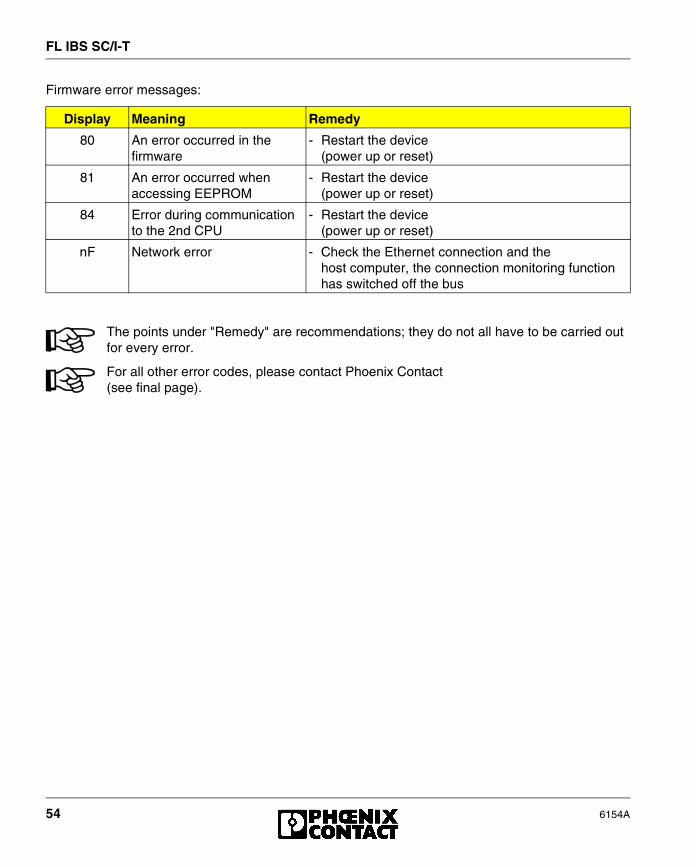
Firmware error messages:
The points under "Remedy" are recommendations; they do not all have to be carried out for every error.
For all other error codes, please contact Phoenix Contact(see final page).
Display Meaning Remedy
80 An error occurred in the firmware
- Restart the device(power up or reset)
81 An error occurred when accessing EEPROM
- Restart the device(power up or reset)
84 Error during communication to the 2nd CPU
- Restart the device(power up or reset)
nF Network error - Check the Ethernet connection and thehost computer, the connection monitoring function has switched off the bus

FL IBS SC/I-T
6154A 55
16 Technical Data
General Data
Function Ethernet/INTERBUS gateway
Housing dimensions (width x height x depth) 45 mm x 99 mm x 112 mm (1.772 in. x 3.898 in. x 4.409 in.)
Permissible operating temperature 0°C to 55°C (32°F to 131°F)
Permissible storage temperature -20°C to 70°C (-4°F to 158°F)
Degree of protection IP 20, DIN 40050, IEC 60529
Class of protection Class 3 VDE 0106; IEC 60536
Humidity (operation) 30% to 95%, no condensation
Humidity (storage) 30% to 95%, no condensation
Air pressure (operation) 86 kPa to 108 kPa, 1500 m (4921 ft.) above sea level
Air pressure (storage) 66 kPa to 108 kPa,3500 m (11483 ft.) above sea level
Preferred mounting position Perpendicular to a standard DIN rail
Connection to functional earth ground Short (< 50 cm [19.69 in.]) low-impedance wire to terminal 3
Environmental compatibility Free from substances that would hinder coating with paint or varnish (according to VW specification)
Resistance to solvents Standard solvents
Resistance to gases that may endanger functions according to DIN 40 436 Parts 36 and 37
Sulfur dioxide (SO2) 10 ± 0.3 cm3/m3
Hydrogen sulfide (H2S) 1 ± 0.3 cm3/m3
each at 25°C (77°F) and 75% humidity and an exposure time of four days
Weight 240 g, typical
I/O Supply Voltage (US)
Connection COMBICON; cable diameter 2.5 mm2 (14 AWG), maximum
Nominal value 24 V DC
Permissible ripple 3.6 Vpp within the permissible voltage range
Permissible voltage range 18.5 V DC to 30 V DC
Current consumption at US 200 mA, typical
FL IBS SC/I-T
56 6154A
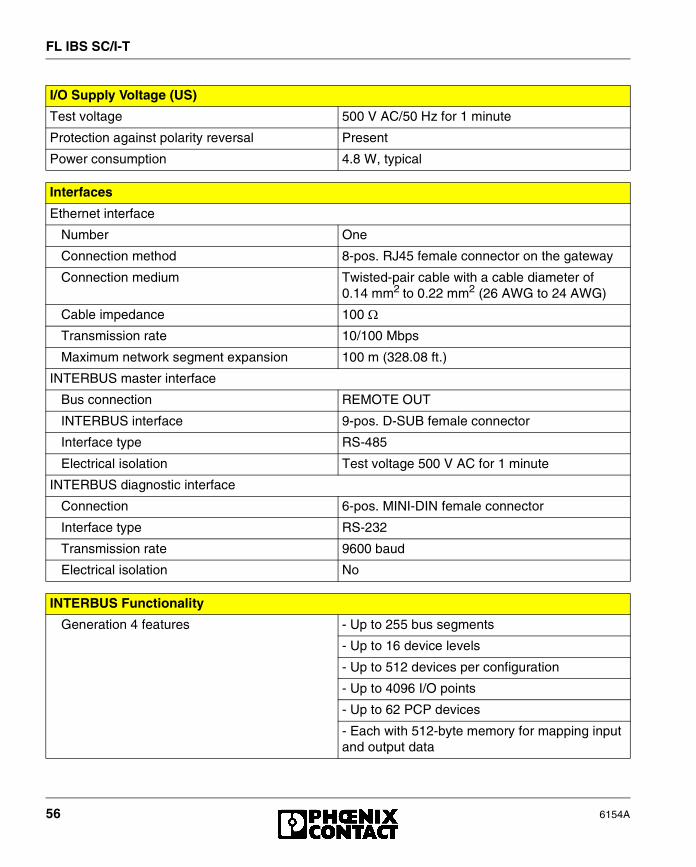
Test voltage 500 V AC/50 Hz for 1 minute
Protection against polarity reversal Present
Power consumption 4.8 W, typical
I/O Supply Voltage (US)
Interfaces
Ethernet interface
Number One
Connection method 8-pos. RJ45 female connector on the gateway
Connection medium Twisted-pair cable with a cable diameter of 0.14 mm2 to 0.22 mm2 (26 AWG to 24 AWG)
Cable impedance 100 �
Transmission rate 10/100 Mbps
Maximum network segment expansion 100 m (328.08 ft.)
INTERBUS master interface
Bus connection REMOTE OUT
INTERBUS interface 9-pos. D-SUB female connector
Interface type RS-485
Electrical isolation Test voltage 500 V AC for 1 minute
INTERBUS diagnostic interface
Connection 6-pos. MINI-DIN female connector
Interface type RS-232
Transmission rate 9600 baud
Electrical isolation No
INTERBUS Functionality
Generation 4 features - Up to 255 bus segments
- Up to 16 device levels
- Up to 512 devices per configuration
- Up to 4096 I/O points
- Up to 62 PCP devices
- Each with 512-byte memory for mapping input and output data

FL IBS SC/I-T
6154A 57
Protocols/MIBs
Supported protocols TCP/IPUDPSNMPBootPTFTPHTTP
Supported standard MIBs RFC 1213 (MIB II)
Supported private MIBs Phoenix Contact MIBFL MIBFL Device MIB
Mechanical Tests
Shock test according to IEC 60068-2-27 Operation: 25g, 11 ms period, half-sine shock pulseStorage/transport: 50g, 11 ms period, half-sine shock pulse
Vibration resistance according to IEC 60068-2-6 Operation/storage/transport: 5g, 150 Hz, Criterion A
Free fall according to IEC 60068-2-32 1 m (3.281 ft.)
Conformance With EMC Directives
Developed according to IEC 61000-6.2
IEC 61000-4-2 (ESD) Criterion B
IEC 61000-4-3 (radiated-noise immunity) Criterion A
IEC 61000-4-4 (burst) Criterion B
IEC 61000-4-5 (surge) Criterion B
IEC 61000-4-6 (conducted noise immunity) Criterion A
EN 55011 (noise emission) Class A

FL IBS SC/I-T
58 6154A
© P
hoen
ix C
onta
ct09
/200
1T
echn
ical
mod
ifica
tions
res
erve
dT
NR
90
06 9
1 9
Phoenix Contact GmbH & Co. KGFlachsmarktstr. 832825 BlombergGermany
+49 - 52 35 - 30 0
+49 - 52 35 - 34 12 00
www.phoenixcontact.comwww.factoryline.defactoryline-service@phoenixcontact.com
Ordering Data
Description Order Designation Order No.
INTERBUS/Ethernet gateway FL IBS SC/I-T 28 31 06 0
CD-ROM with driver software and documentation CD FL IBS SC 28 32 05 6
Startup/diagnostic software - Factory Manager FL SWT 28 31 04 4
INTERBUS operating software (German) IBS CMD SWT G4 27 21 43 9
INTERBUS operating software (English) IBS CMD SWT G4 E 27 21 44 2
OPC server IBS OPC SERVER 27 29 12 7
Programming cable for the connection of CMD via the V.24 interface
PRG CB MINI DIN 27 30 61 1
RJ45 connector set gray for 1:1 cable (2 pieces) FL PLUG RJ45 GR/2 27 44 85 6
RJ45 connector set green for crossed cable (2 pieces) FL PLUG RJ45 GN/2 27 44 57 1
Double sheathed Ethernet cable FL CAT5 HEAVY 27 44 81 4
Flexible Ethernet cable FL CAT5 FLEX 27 44 83 0
Assembly tool for RJ45 connector FL CRIMPTOOL 27 44 86 9
Medium converter 660 nm FL MC 10BASE-T/FO POF 27 44 51 3
Optical fiber interface connector for the REMOTE interface, polymer fiber
OPTOSUB-PLUS-K/OUT 27 99 61 0
Optical fiber interface connector for the REMOTE interface, glass fiber
OPTOSUB-PLUS-G/OUT 27 99 63 6
Interface converter (RS-422 to optical fiber) PSM-EG-RS422/LGL-G 27 61 33 4