DATE: DOCUMENT RELEASE AND CHANGE FORMANSI/HI 14.6, 2016 Rotodynamic Pumps for Hydraulic Performance...
54
1 SPF-001 (Rev.D1) DOCUMENT RELEASE AND CHANGE FORM Prepared For the U.S. Department of Energy, Assistant Secretary for Environmental Management By Washington River Protection Solutions, LLC., PO Box 850, Richland, WA 99352 Contractor For U.S. Department of Energy, Office of River Protection, under Contract DE-AC27-08RV14800 TRADEMARK DISCLAIMER: Reference herein to any specific commercial product, process, or service by trade name, trademark, manufacturer, or otherwise, does not necessarily constitute or imply its endorsement, recommendation, or favoring by the United States government or any agency thereof or its contractors or subcontractors. Printed in the United States of America. Release Stamp 1. Doc No: RPP-SPEC-41399 Rev. 02 2. Title: SPECIFICATION FOR SLURRY PUMP P-B-2 3. Project Number: ☒N/A 4. Design Verification Required: ☐Yes ☒No 5. USQ Number: ☒ N/A N/A-3 6. PrHA Number Rev. ☒ N/A Clearance Review Restriction Type: public 7. Approvals Title Name Signature Date Clearance Review Aardal, Janis D Aardal, Janis D 05/20/2019 Design Authority Balint, Greg G Balint, Greg G 05/13/2019 Checker Barnes, Travis J Barnes, Travis J 05/13/2019 Document Control Approval Manville, Kira Manville, Kira 05/20/2019 Engineering Discipline Lead-Civil/Structural Scott, Mark A Scott, Mark A 05/13/2019 Engineering Discipline Lead-Electrical Rambo, Charles L Rambo, Charles L 05/13/2019 Engineering Discipline Lead-Mechanical Goessmann, Glen E Goessmann, Glen E 05/12/2019 Engineering Hoisting and Rigging SME Mackey, Tom Mackey, Tom 05/06/2019 Originator Servin, Mario A Servin, Mario A 05/11/2019 Quality Assurance Thompson, Tyler J Thompson, Tyler J 05/13/2019 Responsible Engineering Manager Smith, Gregory E Smith, Gregory E 05/14/2019 USQ Evaluator Carlstrom, Richard Carlstrom, Richard 05/13/2019 Welding Engineer Berkey, James Berkey, James 05/06/2019 8. Description of Change and Justification Revision 2 updates specification to current requirements, and updates scope to remove VFD procurement and add procurement of the upper frame assembly. 9. TBDs or Holds ☒N/A 10. Related Structures, Systems, and Components a. Related Building/Facilities ☐N/A b. Related Systems ☐N/A c. Related Equipment ID Nos. (EIN) ☐N/A 242-A 242A P-B-2 P-B-2-M 11. Impacted Documents – Engineering ☒N/A Document Number Rev. Title 12. Impacted Documents (Outside SPF): N/A 13. Related Documents ☒N/A Document Number Rev. Title 14. Distribution Name Organization Balint, Greg G COGNIZANT SYSTEM ENGINEERING Castleberry, Jim L TFP PROJECT MANAGEMENT Houghton, David J TANK FARM PROJECTS & DFLAW ENG Sijgers, Frederik O DESIGN SERVICES Smith, Gregory E TANK FARM PROJECTS ENGINEERING Trevino, Johnny M 242-A EVAPORATOR ENGINEERING RPP-SPEC-41399 Rev.02 5/20/2019 - 11:08 AM 1 of 54 May 20, 2019 DATE:
Transcript of DATE: DOCUMENT RELEASE AND CHANGE FORMANSI/HI 14.6, 2016 Rotodynamic Pumps for Hydraulic Performance...

1 SPF-001 (Rev.D1)
DOCUMENT RELEASE AND CHANGE FORMPrepared For the U.S. Department of Energy, Assistant Secretary for Environmental ManagementBy Washington River Protection Solutions, LLC., PO Box 850, Richland, WA 99352Contractor For U.S. Department of Energy, Office of River Protection, under Contract DE-AC27-08RV14800
TRADEMARK DISCLAIMER: Reference herein to any specific commercial product, process, or service by trade name, trademark, manufacturer, or otherwise, does not necessarily constitute or imply its endorsement, recommendation, or favoring by the United States government or any agency thereof or its contractors or subcontractors. Printed in the United States of America.
Release Stamp
1. Doc No: RPP-SPEC-41399 Rev. 02
2. Title:SPECIFICATION FOR SLURRY PUMP P-B-2
3. Project Number: ☒N/A 4. Design Verification Required:
☐Yes ☒No
5. USQ Number: ☒ N/AN/A-3
6. PrHA Number Rev. ☒ N/A
Clearance Review Restriction Type:public
7. Approvals
Title Name Signature DateClearance Review Aardal, Janis D Aardal, Janis D 05/20/2019Design Authority Balint, Greg G Balint, Greg G 05/13/2019Checker Barnes, Travis J Barnes, Travis J 05/13/2019Document Control Approval Manville, Kira Manville, Kira 05/20/2019Engineering Discipline Lead-Civil/Structural Scott, Mark A Scott, Mark A 05/13/2019Engineering Discipline Lead-Electrical Rambo, Charles L Rambo, Charles L 05/13/2019Engineering Discipline Lead-Mechanical Goessmann, Glen E Goessmann, Glen E 05/12/2019Engineering Hoisting and Rigging SME Mackey, Tom Mackey, Tom 05/06/2019Originator Servin, Mario A Servin, Mario A 05/11/2019Quality Assurance Thompson, Tyler J Thompson, Tyler J 05/13/2019Responsible Engineering Manager Smith, Gregory E Smith, Gregory E 05/14/2019USQ Evaluator Carlstrom, Richard Carlstrom, Richard 05/13/2019Welding Engineer Berkey, James Berkey, James 05/06/2019
8. Description of Change and Justification
Revision 2 updates specification to current requirements, and updates scope to remove VFD procurement and add procurement of the upper frame assembly.
9. TBDs or Holds ☒N/A
10. Related Structures, Systems, and Components
a. Related Building/Facilities ☐N/A b. Related Systems ☐N/A c. Related Equipment ID Nos. (EIN) ☐N/A
242-A 242A P-B-2P-B-2-M
11. Impacted Documents – Engineering ☒N/A
Document Number Rev. Title
12. Impacted Documents (Outside SPF):
N/A
13. Related Documents ☒N/A
Document Number Rev. Title
14. Distribution
Name OrganizationBalint, Greg G COGNIZANT SYSTEM ENGINEERINGCastleberry, Jim L TFP PROJECT MANAGEMENTHoughton, David J TANK FARM PROJECTS & DFLAW ENGSijgers, Frederik O DESIGN SERVICESSmith, Gregory E TANK FARM PROJECTS ENGINEERINGTrevino, Johnny M 242-A EVAPORATOR ENGINEERING
RPP-SPEC-41399 Rev.02 5/20/2019 - 11:08 AM 1 of 54
May 20, 2019DATE:

A-6002-767 (REV 3)
RPP-SPEC-41399, Rev. 2
Specification for Slurry Pump P-B-2
Author Name:
M.A. Servin
Tank Farm Projects EngineeringWashington River Protection Solutions, LLC
Richland, WA 99352U.S. Department of Energy Contract DE-AC27-08RV14800
EDT/ECN: UC:
Cost Center: Charge Code:
B&R Code: Total Pages:
Key Words: P-B-2 Pump, Recirculation Pump, Procurement Specification, 242-A Evaporator
Abstract: This Specification provides the minimum requirements for the design and fabrication of the P-B-2 Pump for use at the 242-A Evaporator, which is located in the 200 East Area of the U.S.Department of Energy’s Hanford Nuclear Waste Site. Construction of the 242-A Evaporator started in 1974 and operation began in 1977. The mission of the 242-A Evaporator is to support environmental restoration and remediation of the Hanford Site by optimizing the 200 Area double-shell tank waste volumes through radioactive liquid waste volume reduction. Volume reduction is accomplished through an evaporation process that uses a conventional forced-circulation, vacuum evaporation system operating at low pressure to concentrate radioactive waste solutions. Pump P-B-2 is the evaporator slurry transfer pump.
TRADEMARK DISCLAIMER. Reference herein to any specific commercial product, process, or service by trade name, trademark, manufacturer, or otherwise, does not necessarily constitute or imply its endorsement, recommendation, or favoring by the United States Government or any agency thereof or its contractors or subcontractors.
Release Approval Date Release Stamp
Approved For Public Release
RPP-SPEC-41399 Rev.02 5/20/2019 - 11:08 AM 2 of 54
By Janis D. Aardal at 11:19 am, May 20, 2019
May 20, 2019DATE:

RPP-SPEC-41399, Rev. 2
Specification for Slurry Pump P-B-2
M.A. ServinTank Farm Projects EngineeringWashington River Protection Solutions LLC
Date PublishedMay 2019
Prepared for the U.S. Department of EnergyOffice of River Protection
P.O. Box 850Richland, Washington
washington riverS protection solutions
RPP-SPEC-41399 Rev.02 5/20/2019 - 11:08 AM 3 of 54

RPP-SPEC-41399, Rev. 2
i
TABLE OF CONTENTS
1.0 SCOPE ............................................................................................................................ 1-1
2.0 APPLICABLE DOCUMENTS..................................................................................... 2-1
2.1 NON-GOVERNMENT DOCUMENTS.............................................................. 2-1
2.2 NON-CODE OF RECORD DOCUMENTS ....................................................... 2-2
2.3 GOVERNMENT DOCUMENTS........................................................................ 2-3
3.0 TECHNICAL REQUIREMENTS ............................................................................... 3-1
3.1 ITEM DEFINITION ............................................................................................ 3-1
3.2 INTERFACE DEFINITION................................................................................ 3-23.2.1 Pump Assembly Interface with 242-A Evaporator .................................. 3-23.2.2 Suction and Discharge Piping Interface................................................... 3-23.2.3 MCS and Electrical Service Interface...................................................... 3-23.2.4 Water Service (Seal - Barrier Fluid) Interface......................................... 3-33.2.5 Motor Bearing Grease Interface............................................................... 3-33.2.6 Interface Critical Dimensions .................................................................. 3-3
3.3 CHARACTERISTICS ......................................................................................... 3-43.3.1 General Requirements.............................................................................. 3-43.3.2 Pump Functional Characteristics ............................................................. 3-43.3.3 Fluid Characteristics ................................................................................ 3-43.3.4 Ambient Conditions ................................................................................. 3-53.3.5 Seal Water................................................................................................ 3-53.3.6 Pump Characteristics ............................................................................... 3-63.3.7 Pump Materials of Construction .............................................................. 3-83.3.8 Reliability................................................................................................. 3-93.3.9 Maintainability......................................................................................... 3-93.3.10 Electrical/Electronic Product Acceptability........................................... 3-10
3.4 DESIGN AND CONSTRUCTION ................................................................... 3-103.4.1 Design Pressure...................................................................................... 3-113.4.2 ASME B31.3 Design/Analysis .............................................................. 3-113.4.3 Structural Design Analysis & Lifting Analysis ..................................... 3-11
3.5 DRAWINGS AND MANUALS........................................................................ 3-12
3.6 FABRICATION/ASSEMBLY PROCESSES ................................................... 3-133.6.1 Cleaning and Painting ............................................................................ 3-133.6.2 Special Tools.......................................................................................... 3-153.6.3 Marking.................................................................................................. 3-15
4.0 QUALITY ASSURANCE REQUIREMENTS............................................................ 4-1
4.1 QUALITY ASSURANCE PROGRAM .............................................................. 4-1
RPP-SPEC-41399 Rev.02 5/20/2019 - 11:08 AM 4 of 54

RPP-SPEC-41399, Rev. 2
ii
4.2 QUALIFICATIONS ............................................................................................ 4-14.2.1 Welding Personnel and Procedures ......................................................... 4-14.2.2 Welding Inspectors and Procedures......................................................... 4-2
4.3 INSPECTIONS AND TESTING......................................................................... 4-24.3.1 Weld Inspection and Examination ........................................................... 4-34.3.2 Megger Test ............................................................................................. 4-44.3.3 Pump Motor Driver Testing..................................................................... 4-44.3.4 Hydrostatic Pressure Testing ................................................................... 4-44.3.5 Continuous Run Test................................................................................ 4-44.3.6 Performance Test ..................................................................................... 4-54.3.7 Pump Sealing System Leak Inspection.................................................... 4-54.3.8 Factory Test Data..................................................................................... 4-5
5.0 DOCUMENT SUBMITTAL......................................................................................... 5-1
5.1 APPROVAL OF SUBMITTALS ........................................................................ 5-2
5.2 LIST OF SUBMITTALS..................................................................................... 5-3
6.0 PREPARATION FOR DELIVERY............................................................................. 6-1
6.1 PRESERVATION AND PACKAGING ............................................................. 6-1
6.2 MARKING .......................................................................................................... 6-1
6.3 SHIPPING AND HANDLING............................................................................ 6-1
6.4 TRANSPORTATION.......................................................................................... 6-2
7.0 REFERENCES............................................................................................................... 7-1
8.0 NOTES............................................................................................................................ 8-1
8.1 LIST OF ACRONYMS ....................................................................................... 8-1
8.2 UNITS.................................................................................................................. 8-2
9.0 APPENDIX A – PUMP CURVE FOR FACILITY PUMP........................................ 9-1
9.1 APPENDIX A – PUMP CURVE FOR FACILITY PUMP ................................ 9-1
RPP-SPEC-41399 Rev.02 5/20/2019 - 11:08 AM 5 of 54

RPP-SPEC-41399, Rev. 2
iii
LIST OF FIGURES
Figure 3-1. Existing P-B-2 Pump Assembly................................................................................ 3-1
LIST OF TABLES
Table 2-1. Non-Government Code of Record Documents .......................................................... 2-1Table 2-2. Non-Government Non-Code of Record Documents ................................................. 2-2Table 2-3. Government Documents............................................................................................. 2-3Table 3-1. Pump Performance Characteristics............................................................................. 3-4Table 3-2. Fluid Properties (Slurry)............................................................................................. 3-5Table 3-3. Coating Schedule...................................................................................................... 3-14Table 4-1. Test Parameters .......................................................................................................... 4-6Table 5-1. Summary of Submittals .............................................................................................. 5-2
RPP-SPEC-41399 Rev.02 5/20/2019 - 11:08 AM 6 of 54

RPP-SPEC-41399, Rev. 2
1-1
1.0 SCOPE
This Specification provides the minimum requirements for the design and fabrication of centrifugal, single stage pump (referred to as the P-B-2 pump) for use at the 242-A Evaporator, in the 200 East Area of the U.S. Department of Energy’s Hanford Nuclear Waste Site. Construction of the 242-A Evaporator started in 1974 and operation began in 1977. The mission of the 242-A Evaporator is to support environmental restoration and remediation of the Hanford Site by optimizing the 200 Area double-shell tank waste volumes through radioactive liquid waste volume reduction. Volume reduction is accomplished through an evaporation process that uses a conventional forced-circulation, vacuum evaporation system operating at low pressure to concentrate radioactive waste solutions. Pump P-B-2 is the evaporator slurry transfer pump.
For this scope, work includes design, fabrication, assembly, inspection, testing, documentation, packaging, and shipping of a centrifugal, single stage pump designed to interface with the existing 242-A Evaporator. A portion of the pump assembly has been designed, and will not be included within the Sellers scope. This scope includes the pump-motor assembly, base frame, upper frame, piping with specialty mechanical and electrical connectors, and any custom handling equipment required to transport/install the pump assembly.
Work does not include site services, installation, or operation of site equipment.
Government furnished equipment (GFE) include:
2”, Kick-Off Plate (H-2-30600, “Standard Square Kick-Off Plate for Male Connectors”), 2”, Male PUREX Nozzle (H-2-90185, “Male Nozzle 2” PUREX”), 3”, Male PUREX Nozzle (H-2-90186, “Male Nozzle 3” PUREX”), 2”, 3-Way Connector Nozzles (H-2-32447, “Details & Assy. Stainless Steel 2”-3 Way Conn.
Nozzle”), and Lower Electrical Connector (H-2-32401, “Assembly Lower Electrical Equip. Connector”).
RPP-SPEC-41399 Rev.02 5/20/2019 - 11:08 AM 7 of 54
RPP-SPEC-41399, Rev. 2
2-1
2.0 APPLICABLE DOCUMENTS
2.1 NON-GOVERNMENT DOCUMENTS
The following documents of the exact issue shown in Table 2-1 form a part of this Specificationto the extent specified herein and establish the Code of Record (COR). In the event of a conflict between documents referenced herein and the requirements of this Specification, the Buyer shall be notified to obtain interpretation and clarification.
Table 2-1. Non-Government Code of Record Documents
Industry Consensus Codes And Standards
Document Number Title
ANSI/ABMA/ISO 3290, 2014
Rolling Bearings – Balls – Part 1: Steel Balls, Anti-Friction Bearing Manufacturers Association Inc. (ABMA), Vienna, Virginia.
ANSI/HI 14.6, 2016 Rotodynamic Pumps for Hydraulic Performance Acceptance Tests, ANSI/Hydraulic Institute (HI), New York, New York.
ANSI NEMA Standard MG-1, 2016
Motors and Generators, National Electrical Manufacturers Association (NEMA), Arlington, Virginia.
API Standard 610, 2010 Centrifugal Pumps for Petroleum, Petrochemical and Natural Gas Industries, American Petroleum Institute (API), Washington DC.
ASCE 07, 2015 Minimum Design Loads for Buildings and Other Structures, American Society of Civil Engineers (ASCE), Reston, Virginia.
ASME B&PVC,Section IX, 2017
Boiler and Pressure Vessel Code (B&PVC) – Welding and Brazing Qualifications, American Society of Mechanical Engineers (ASME), New York, New York.
ASME B31.3, 2016 Process Piping, American Society of Mechanical Engineers, New York, New York.
ASME BTH-1, 2017 Design Below-the-Hook Lifting Devices, American Society of Mechanical Engineers, New York, New York.
ASME Y14.1, 2012 Decimal Inch Drawing Sheet Size and Format, American Society of Mechanical Engineers, New York, New York.
ASME Y14.2M, 2008 Line Conventions and Lettering, American Society of Mechanical Engineers, New York, New York.
ASME Y14.3, 2018 Orthographic and Pictorial Views , American Society of Mechanical Engineers, New York, New York.
ASME Y14.5, 2018 Dimensioning and Tolerancing, American Society of Mechanical Engineers, New York, New York.
ASME Y14.38, 2013 Abbreviations and Acronyms for Use on Drawings and Related documents, American Society of Mechanical Engineers, New York, New York.
ASNT SNT-TC-1A, 2016
Recommended Practice, American Society for Nondestructive Testing (ASNT), Columbus, Ohio.
ASTM A 995/A 995M-2019
Standard Specification for Castings, Austenitic-Ferritic (Duplex) Stainless Steel, for Pressure-Containing parts, American Society for Testing and Materials (ASTM International), West Conshohocken, PA.
AWS D1.1, 2016 Structural Welding Code - Steel, American Welding Society (AWS), Miami, Florida.
AWS D1.6, 2017 Structural Welding Code – Stainless Steel, American Welding Society, Miami, Florida.
RPP-SPEC-41399 Rev.02 5/20/2019 - 11:08 AM 8 of 54

RPP-SPEC-41399, Rev. 2
2-2
AWS QC1, 2016 Specification for AWS Certification of Welding Inspectors, 6th Edition, American Welding Society, Miami, Florida.
IEC 60034-14, 2017 Rotating electrical machines – Part 14: Mechanical vibration of certain machines with shaft heights 56 mm and higher – Measurement, evaluation and limits of vibration severity, International Electrotechnical Commission, Geneva, Switzerland.
IEEE 112-2017 IEEE Standard Test Procedure for Polyphase Induction Motors and Generators, Institute of Electrical and Electronics Engineers, New York, New York.
IEEE 118 Standard Test Code for Resistance Measurement, Institute of Electrical and Electronics Engineers, New York, New York.
IEEE 119 Recommended Practice for General Principles of Temperature Measurement as Applied to Electrical Apparatus, Institute of Electrical and Electronics Engineers, New York, New York.
ISO 1940-1, 2003 Mechanical Vibration Balance Requirements for Rotors in a Rigid State. International Organization for Standardization, Geneva, Switzerland.
Hydraulic Institute Hydraulic Institute Standards, ANSI/Hydraulic Institute (HI), New York, New York.
NIST Handbook 143,5th Edition, 2007
State Weights and Measures Laboratories Program Handbook, National Institute of Standards and Technology (NIST), Harris, G.L., Gaithersburg, Maryland.
MSS SP-54, 2013 Quality Standard for Steel Castings for Valves, Flanges, Fittings, and other Piping Components – Radiographic Examination Method, Manufacturer’s Standardization Society of the Valve and Fittings Industry (MSS), Vienna, Virginia.
MSS SP-55, 2011 Quality Standard for Steel Castings for Valves, Flanges, Fittings, and other Piping Components – Visual Method for Evaluation of Surface Irregularities, Manufacturer’s Standardization Society of the Valve and Fittings Industry (MSS), Vienna, Virginia.
Technical society and technical association Specifications and standards are generally available for reference from libraries or they may be obtained directly from the Technical Society/Association.
2.2 NON-CODE OF RECORD DOCUMENTS
The following documents of the exact issue shown in Table 2-2 are utilized in, or referenced by this document, form a part of this Specification to the extent specified herein but are not considered to be COR documents.
Table 2-2. Non-Government Non-Code of Record Documents
Document Number Title
H-2-30600, Sheet 1 Standard Square Kick-Off Plate for Male Connectors
H-2-32447, Sheet 1 Details & Assy. Stainless Steel 2”-3 Way Conn. Nozzle
H-2-32401, Sheet 1 - 2 Assembly Lower Electrical Equip. Connector
H-2-99014, Sheet 1 Piping P-B-2 Pump Assembly and Details
H-2-836547, Sheet 1 - 5 Piping P-B-2 Pump Assembly
H-2-836548, Sheet 1 - 2 Structural P-B-2 Pump Upper Frame Assembly
H-2-836550, Sheet 1 - 2 Electrical P-B-2 Pump Electric Power Conn Lead Assembly
H-2-836551, Sheet 1 Instrumentation P-B-2 Pump Instr and Controls Assembly
H-2-90185, Sheet 1 - 2 Male Nozzle 2” PUREX
RPP-SPEC-41399 Rev.02 5/20/2019 - 11:08 AM 9 of 54

RPP-SPEC-41399, Rev. 2
2-3
Table 2-2. Non-Government Non-Code of Record Documents
Document Number Title
H-2-90186, Sheet 1 - 2 Male Nozzle 3” PUREX
H-2-99008, Sheet 1 Piping P-B-2 Pump & Base Assembly
RPP-14541, Rev. 8 Jumper Fabrication and Testing Specification for Tank Farms
RPP-8360, Rev 7 Lifting Attachment and Lifted Item Evaluation
TFC-BSM-IRM_DC-C-07 Vendor Processes
TFC-ENG-STD-06 Design Loads for Tank Farms
TFC-ENG-STD-34 Standard for the Selection of Non-Metallic Materials in Contact with Tank Waste
2.3 GOVERNMENT DOCUMENTS
Documents listed in Table 2-3 constitute a part of this Specification to the extent specified herein. The most current version of the documents shall be used unless otherwise specified. In the event of conflict between the documents referenced herein and the contents of this Specification, the Buyer shall be notified to obtain interpretation and clarification.
Table 2-3. Government Documents
Document Number Title
49 CFR 393, Subpart I Protection Against Shifting and Falling Cargo
RPP-SPEC-41399 Rev.02 5/20/2019 - 11:08 AM 10 of 54

RPP-SPEC-41399, Rev. 2
3-1
3.0 TECHNICAL REQUIREMENTS
3.1 ITEM DEFINITION
The P-B-2 pump assembly is a single stage, frame mounted, direct driven through a reliable coupling, with oil lubricated bearings, end suction, top center discharge, horizontal centrifugal pump. The pump assembly shall conform to API 610, or a proven alternative standard, except as modified and supplemented by this Specification. The P-B-2 pump assembly consists of a pump-motor assembly, a base frame, an upper frame and all piping with specialty mechanical and electrical connectors.
The P-B-2 pump is in a heavily shielded, high radiation, pump room, which prevents normal access for typical maintenance, installation and removal activities. Concrete cover blocks are required to be removed to gain access to the pump. Figure 3-1 provides an illustration of anexisting P-B-2 Pump Assembly.
The P-B-2 pump is a general service (GS), quality level 3 (QL-3) piece of equipment.
Figure 3-1. Existing P-B-2 Pump Assembly
RPP-SPEC-41399 Rev.02 5/20/2019 - 11:08 AM 11 of 54

RPP-SPEC-41399, Rev. 2
3-2
3.2 INTERFACE DEFINITION
3.2.1 Pump Assembly Interface with 242-A Evaporator
The pump interfaces with existing facility piping jumpers, utilities, Monitoring and Control System (MCS), and overhead crane for lifting.
The pump is lifted and installed using an overhead crane. Mechanical and electrical interfaces are made using specialty mechanical and electrical connectors, which will be supplied by the Buyer for pump construction. A variable frequency drive exists at the facility that will be used to operate the pump. The interfaces are defined on existing design details. The following interfaces are identified for the pump:
Suction and Discharge Piping Interface. MCS and Electrical Service Interface. Water Service (Seal - Barrier Fluid) Interface. Vibration Monitoring System Interface. Motor Bearing Grease Interface.
3.2.2 Suction and Discharge Piping Interface
Two specialty mechanical connector nozzles will be furnished by the Buyer for the pump suction and discharge to be mounted on the pump assembly. The design includes a jumper with a 3” PUREX nozzle (See H-2-90186) for the pump suction and a jumper with a 2” PUREX nozzle (See H-2-90185) for the pump discharge. These nozzles will mate with existing facility jumpers and piping.
3.2.3 MCS and Electrical Service Interface
The pump will be operated via facility installed ABB ACS800 variable frequency drive (VFD). 460V electric power will be supplied to the pump through an electrical jumper. See H-2-836550 for wiring details.
Additionally, the pump assembly will include an encoder (See Section 3.3.6.5.a), thermistors (See Section 3.3.6.3.h) and a vibration transducer. The vibration shall be as described on the current assembly drawings, or approved equal. Feedback from these instruments will be provide to the MSC via an electrical jumper. See H-2-836551 for wiring details.
For both jumpers, a specialty electrical lower and upper connector is required. The buyer will provide the lower connectors (H-2-32401, Assembly 3) to be mounted by the Seller on the pump assembly. The upper connectors will not be supplied by the Buyer for testing purposes. The wiring of the lower connectors shall match the current configuration.
RPP-SPEC-41399 Rev.02 5/20/2019 - 11:08 AM 12 of 54

RPP-SPEC-41399, Rev. 2
3-3
3.2.4 Water Service (Seal - Barrier Fluid) Interface
Filtered raw water service is available for pump seal, See Section 3.3.5 for details.
Currently the pump seal is started on filtered raw water, and once the waste evaporation process is running, this is switched to process condensate. This has the advantages of being slightly cleaner than the raw water, and also minimizes water additions to the process.
The seal barrier fluid is provided to the pump through a facility jumper that mates with the Buyer furnished 2-inch, 3-way connector nozzle (See Drawing H-2-32447). The pump assembly shall include a nozzle for seal water drainage. The facility is equipped with a drain to catch the seal water as it is discharged from the drain nozzle.
3.2.5 Motor Bearing Grease Interface
The current pump design drawings includes a 2-in, 3-way connector nozzle (H-2-32447) for the motor bearing grease lines. This nozzle will not be used. ECN-712852 modifies the pump design to remove the grease nozzle and piping and replace them with local grease nipples and grease traps installed at the front and rear of the motor, to permit manual lubrication during maintenance between evaporator campaigns. The Buyer will provide the Seller with updated pump assembly drawings with this change incorporated.
3.2.6 Interface Critical Dimensions
The pump assembly will be installed in an existing facility using the current piping jumpers. The goal is to avoid any modifications to these jumpers. Therefore, the critical dimensions of the P-B-2 pump are the dimensions that affect the interface points of the pump, which include, but are not limited to:
1. Location of all mechanical and electrical connections to existing facility jumpersincluding instrumentation signals,
2. Location of anchorage points (e.g., nut retainers) and dowel holes, 3. Access for removal and handling of the new pump.
The Seller is responsible for identifying any modification to the pump that can affect the critical dimensions. The Buyer shall review and approve any of these modifications.
RPP-SPEC-41399 Rev.02 5/20/2019 - 11:08 AM 13 of 54

RPP-SPEC-41399, Rev. 2
3-4
3.3 CHARACTERISTICS
3.3.1 General Requirements
The Seller shall design, fabricate, inspect, test, package, and ship the pump assembly and all associated equipment, in accordance with the codes and standards listed in this Specification. Any deviation from the referenced codes and standards shall have prior written approval from the Buyer. If any conflicting requirements are identified within this Specification, deviations from such requirements, shall have prior approval from the Buyer.
The assembly drawing of the pump is shown in H-2-836547, Sheets 1 – 5. This drawing set shallbe used for component type, arrangement, connection position and orientation and dimensions.
The only design scope within the Seller’s scope is for Item 23 of H-2-836547, Sheet 1, which includes slurry pump mounted on skid. All other portions of the assembly, the Buyer will maintain Design Agent responsibility. Drawing H-2-99008, Sheet 1, should be used for design of the pump and base assembly. The upper frame assembly and skid piping has been designed (See H-2-836548, Sheets 1 – 2) and analyzed (See Sections 3.4.2 and 3.4.3). The Seller should not modify this design. The Seller shall ensure the pump and base assembly can interface with the upper frame and all piping connections.
This Specification supersedes any equivalent references found on these drawings.
3.3.2 Pump Functional Characteristics
The pump shall have a stable head/capacity curve that continuously rises from run-out to shut-off. The hydraulic requirements of the pump are detailed in Conditions 1-3, shown in Table 3-1. Appendix A provides the pump curves for the currently installed pump at the facility.
Table 3-1. Pump Performance Characteristics
Rated Conditions Condition 1 Condition 2 Condition 3Flow 78 gpm 78 gpm 60 gpmTotal Dynamic Head 513 ft 600 ft 443 ftSuction Pressure 5.44 psig 2.67 psig -2.63 psigNPSH Available 23.4 ft 24.8 ft 23.72 ft
Pumped Fluid Conditions Condition 1 Condition 2 Condition 3Temperature 180°F 140°F 110°FSpecific Gravity 1.8 1.54 1.05Viscosity 1-60 cp 1-40 cp 1-60 cpVapor Pressure 2.03 psia 0.97 psia 1.27 psia
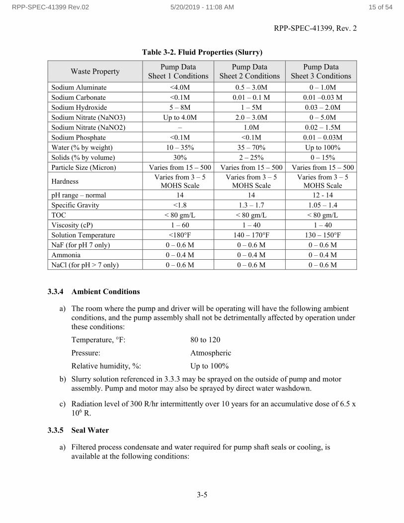
3.3.3 Fluid Characteristics
The pump shall transfer a fluid ranging in character from plain water to radioactive slurry with a radiation level of 300 R/hr. Slurry descriptions are given in Table 3-2.
RPP-SPEC-41399 Rev.02 5/20/2019 - 11:08 AM 14 of 54
RPP-SPEC-41399, Rev. 2
3-5
Table 3-2. Fluid Properties (Slurry)
Waste PropertyPump Data
Sheet 1 ConditionsPump Data
Sheet 2 ConditionsPump Data
Sheet 3 Conditions
Sodium Aluminate <4.0M 0.5 – 3.0M 0 – 1.0M
Sodium Carbonate <0.1M 0.01 – 0.1 M 0.01 –0.03 M
Sodium Hydroxide 5 – 8M 1 – 5M 0.03 – 2.0M
Sodium Nitrate (NaNO3) Up to 4.0M 2.0 – 3.0M 0 – 5.0M
Sodium Nitrate (NaNO2) – 1.0M 0.02 – 1.5M
Sodium Phosphate <0.1M <0.1M 0.01 – 0.03M
Water (% by weight) 10 – 35% 35 – 70% Up to 100%
Solids (% by volume) 30% 2 – 25% 0 – 15%
Particle Size (Micron) Varies from 15 – 500 Varies from 15 – 500 Varies from 15 – 500
HardnessVaries from 3 – 5
MOHS ScaleVaries from 3 – 5
MOHS ScaleVaries from 3 – 5
MOHS Scale
pH range – normal 14 14 12 - 14
Specific Gravity <1.8 1.3 – 1.7 1.05 – 1.4
TOC < 80 gm/L < 80 gm/L < 80 gm/L
Viscosity (cP) 1 – 60 1 – 40 1 – 40
Solution Temperature <180°F 140 – 170°F 130 – 150°F
NaF (for pH 7 only) 0 – 0.6 M 0 – 0.6 M 0 – 0.6 M
Ammonia 0 – 0.4 M 0 – 0.4 M 0 – 0.4 M
NaCl (for pH > 7 only) 0 – 0.6 M 0 – 0.6 M 0 – 0.6 M
3.3.4 Ambient Conditions
a) The room where the pump and driver will be operating will have the following ambient conditions, and the pump assembly shall not be detrimentally affected by operation underthese conditions:
Temperature, °F: 80 to 120
Pressure: Atmospheric
Relative humidity, %: Up to 100%
b) Slurry solution referenced in 3.3.3 may be sprayed on the outside of pump and motor assembly. Pump and motor may also be sprayed by direct water washdown.
c) Radiation level of 300 R/hr intermittently over 10 years for an accumulative dose of 6.5 x 10⁶ R.
3.3.5 Seal Water
a) Filtered process condensate and water required for pump shaft seals or cooling, isavailable at the following conditions:
RPP-SPEC-41399 Rev.02 5/20/2019 - 11:08 AM 15 of 54
RPP-SPEC-41399, Rev. 2
3-6
Filtered to 5 micron.
Max Temperature 120°F.
pH 9-11, with up to 0.4M ammonia (6.8 g/L)
Capacity shall range from 0.5 to 1.76 gpm at 140 psig. (Capacity and pressure canbe regulated below the maximum values presented).
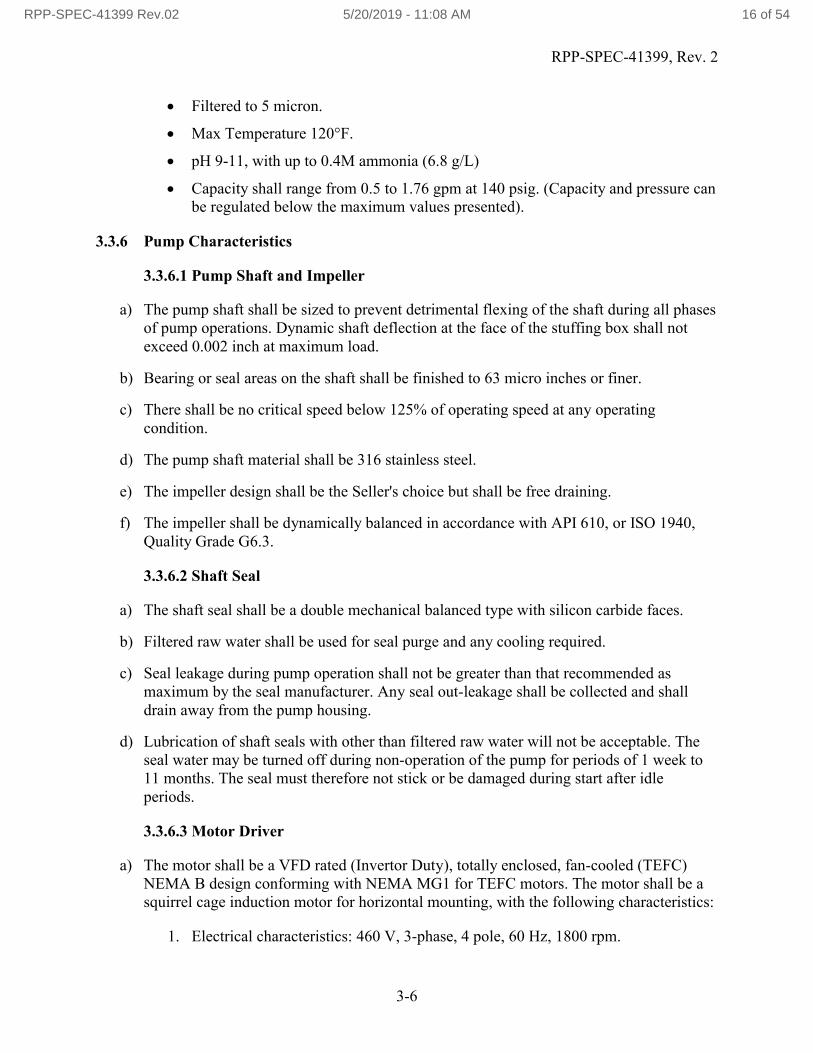
3.3.6 Pump Characteristics
3.3.6.1 Pump Shaft and Impeller
a) The pump shaft shall be sized to prevent detrimental flexing of the shaft during all phases of pump operations. Dynamic shaft deflection at the face of the stuffing box shall not exceed 0.002 inch at maximum load.
b) Bearing or seal areas on the shaft shall be finished to 63 micro inches or finer.
c) There shall be no critical speed below 125% of operating speed at any operating condition.
d) The pump shaft material shall be 316 stainless steel.
e) The impeller design shall be the Seller's choice but shall be free draining.
f) The impeller shall be dynamically balanced in accordance with API 610, or ISO 1940, Quality Grade G6.3.
3.3.6.2 Shaft Seal
a) The shaft seal shall be a double mechanical balanced type with silicon carbide faces.
b) Filtered raw water shall be used for seal purge and any cooling required.
c) Seal leakage during pump operation shall not be greater than that recommended as maximum by the seal manufacturer. Any seal out-leakage shall be collected and shall drain away from the pump housing.
d) Lubrication of shaft seals with other than filtered raw water will not be acceptable. The seal water may be turned off during non-operation of the pump for periods of 1 week to 11 months. The seal must therefore not stick or be damaged during start after idle periods.
3.3.6.3 Motor Driver
a) The motor shall be a VFD rated (Invertor Duty), totally enclosed, fan-cooled (TEFC) NEMA B design conforming with NEMA MG1 for TEFC motors. The motor shall be a squirrel cage induction motor for horizontal mounting, with the following characteristics:
1. Electrical characteristics: 460 V, 3-phase, 4 pole, 60 Hz, 1800 rpm.
RPP-SPEC-41399 Rev.02 5/20/2019 - 11:08 AM 16 of 54

RPP-SPEC-41399, Rev. 2
3-7
2. Insulation: Class H, minimum.
3. Speed: Motor and pump variable from 700 to 3450 rpm, based on a variable frequency drive operating between 23 and 115 Hz.
4. Bearings: Bearings shall be regreasable anti-friction type, 60,000 hour, shielded, mounted in large prepacked grease chambers, incorporating heavy-duty shaft seals to prevent grease from entering the motor. Grease for bearings shall be Alvania No. 2 radiation resistant grease, or equal, as approved by the Buyer. Grease inlet and outlet shall be ¼ inches NPT (F).
b) Motor size shall be selected to give the required horsepower and starting torque with a sufficient factor of safety to prevent overloading.
c) The pump motor shall be sized such that the pump will not overload the motor at any point on the performance curve when pumping a liquid at the operating conditions specified in Paragraph 3.3.2. It shall be the Seller's responsibility to select a motor ofsufficient size to meet the above conditions.
d) The duty rating, motor mounting assembly, shaft rotation, and frame size shall be selected to suit the equipment furnished and in accordance with NEMA MG1.
e) The motor size shall not be less than 150 HP with a 1.15 service factor.
f) The motor will be operated from 23 to 115 Hz from a variable frequency drive described in Section 3.2.3. Hence, the motor shall be balanced for operations at 3450 rpm. Thevariable frequency drive will be set to allow the motor to produce a starting torque of 200% of full load torque; therefore, breakdown torque shall be a minimum of 200% of full load torque. The Seller shall be responsible for sizing the motor so that it meets the required starting torque within the operating range.
g) The motor shaft opposite the drive end shall be extended and machined to interface with the flange, adapter, and encoder shown on H-2-99008. The encoder, adapter, and flange shall be mounted on shaft prior to balancing.
h) Stator windings shall include three positive temperature coefficient thermistors. The leads shall be wired to an external auxiliary junction box on the motor. See Drawing H-2-99008 for box location. A control relay sensitive to change in thermistor resistance isinstalled in the variable frequency drive. This control relay provides a contact opening during high temperature to shut the motor down. Temperature settings shall be based on ambient described in Paragraph 3.3.4.
i) The coupling between motor and pump shall be Falk Steelflex Type TIO, or equal, as approved by the Buyer.
j) The procedures given in IEEE STD. 118 and IEEE STD. 119 should be used when measuring the resistance of the stator winding.
RPP-SPEC-41399 Rev.02 5/20/2019 - 11:08 AM 17 of 54
RPP-SPEC-41399, Rev. 2
3-8
3.3.6.4 Oil Level Indicator
An oil level indicator shall be provided as shown in H-2-99008, along with the manufacturer’s standard indicator.
3.3.6.5 Instrumentation
a) The pump motor shall be equipped with a resistive-magneto type encoder for providing a feedback signal to the variable frequency drive. The encoder shall be as described on Drawing H-2-99008, or approved equal.
b) Pump motor shall be equipped with positive temperature coefficient thermistors described in Paragraph 3.3.6.3.h.
3.3.7 Pump Materials of Construction
c) Material and components shall be new.
d) All metal components in contact with the pumped fluid shall be duplex CD4MCuN stainless steel, or a Buyer approved material having the same or superior corrosion and abrasion resistant characteristics to the process slurry.
e) The pump casing shall be cast per ASTM A995 Grade 1B. The casting surface texture of the pump casing shall be as smooth as or smoother than ACI Surface Indicator Scale-3, as cited in the SAE Handbook. In addition to the visual examinations to the casting surface per ASTM A 995, the supplementary requirement S5 radiographic examination shall be performed. The acceptance criteria shall be MSS SP-54. All mating surfaces and flashings shall be ground smooth. The interior of the casting shall have an RMS rating of 200 or finer, with no rough or pitted surfaces. As an alternative, MSS SP-55 may be used for visual evaluation of the casting surface finish. The pump shall be equipped with a casing drain plug.
f) Metal components of the shaft seal shall be 300 series austenitic stainless steel, or shall be approved in writing by the Buyer.
g) Pump Bearings: Pump bearings shall be oil lubricated and completely protected from process solution and seal or bearing cooling water. Where ball bearings are used, the balls shall be in accordance with the requirements of ANSI/ABMA/ISO 3290 (previously ABMA-10).
h) All elastomer materials used in fabrication shall be ethylene propylene diene monomer (EPDM), and shall be certified by letter from the pump supplier. All elastomers used shall comply with TFC-ENG- STD-34, Standard for the Selection of Non-Metallic Materials in Contact with Tank Waste.
i) Material selection shall be identified within the design data for Buyer review and approval prior to the start of fabrication, and material certification data shall be submitted prior to shipment for Buyer approval. Material identification shall include the applicable
RPP-SPEC-41399 Rev.02 5/20/2019 - 11:08 AM 18 of 54
RPP-SPEC-41399, Rev. 2
3-9
ASTM Specification number and any proposed supplementary feature listed as optional in the ASTM Specifications. Material certification shall present the results of chemical analysis and physical tests required in applicable ASTM Specifications.
j) Threaded pipe joints shall be lubricated before assembly.
k) Brass, aluminum, bronze, and copper base materials, shall not be used in a location that is normally wetted by the pumped waste fluid.
l) The materials of construction shall be chosen to prevent differential thermal expansion of the individual pump components (i.e. shaft) from adversely affecting the performance of the pump over the specified range of operating temperatures.
m) All major pressure boundary and rotating parts shall be furnished to ASTM material Specifications and shall include Certified Material Test Reports (CMTRs).
n) Materials used for other parts shall be clearly identified on the bill of material as to material type and grade; however, CMTR are not required. Materials shall be non-asbestos, non-absorbent and suitable for the chemical and radiation environment in which they are used.
3.3.8 Reliability
To meet reliability requirements, the following concepts shall be used:
a) The pump shall be capable of operating over 10 years. The pump shall meet the three different operating conditions specified in Section 3.3.2. The expected quantities to be pumped over the 10 year life are: 1,000,000 gallons for condition 1; 10,000,000 gallons for condition 2; and 54,000,000 gallons for condition 3.
3.3.9 Maintainability
a) Complete installation, operation, and maintenance manuals shall be provided for all equipment. The manuals shall contain all information necessary for complete onsite repair and rebuild including specifying individual component sourcing, assembly tolerances and runout allowances.
b) Pump assembly should consider easy disassembly such that it can be taken apart, repaired, and put together while wearing a respirator and canvas gloves.
c) The use of unique equipment or special components for assembly, installation, repair and maintenance shall be minimized. Two sets of any special tools required shall be provided to the Buyer.
RPP-SPEC-41399 Rev.02 5/20/2019 - 11:08 AM 19 of 54

RPP-SPEC-41399, Rev. 2
3-10
3.3.10 Electrical/Electronic Product Acceptability
a) Each product shall be listed for its intended use in at least one of the following documents and shall bear the listing organization's label. In the absence of this label, documentation shall be provided that verifies product listing.
1. FM Approval Guide,
2. UL Electrical Appliance and Utilization Equipment Directory,
3. UL Electrical Construction Materials Directory, or
4. ETL Test Laboratory, Inc.
b) If the product is not listed in one of the above directories or guide, then a product shall be provided that has been tested and certified by a nationally recognized laboratory in accordance with 29 CFR 1910.7. The following documentation shall be provided.
1. OSHA documentation that demonstrates recognition of the laboratory. UL Electrical Appliance and Utilization Equipment Directory,
2. Laboratory documentation that verifies testing in accordance with a national code or standard.
c) If the product is not listed by UL, FIM, or ETL and if a nationally recognized laboratory certification is not available, descriptive literature shall be submitted to the Buyer for approval. Literature shall include product specification and a description of the intended application.
3.4 DESIGN AND CONSTRUCTION
The pump assembly shall be built in compliance with the Hydraulic Institute Standards, or proven alternative design standards approve by the Buyer. These standards shall be considered an integral part of this Specification, and shall be complied with except as modified or supplemented herein. The pump shall be designed and constructed in accordance with the manufacturer’s standard practices, and approved design and fabrication details.
The Seller shall prepare a Pump Design Report that documents the material selection, design,component Specification data, electrical product acceptability, drawings for the pump and motor driver, and a 3-dimensional computer aided design solid body model of the pump assembly.
Following completion of fabrication, assembly and testing, the Seller shall develop a Final Pump Data Package. This package shall include the Pump Design Report, all testing procedures and results documentation; completed shop travelers, welder qualifications and nondestructive examination (NDE) procedures, with NDE personnel qualifications; chemical and physical test reports; inspection/examination reports; updated vendor data and as-built drawings including a finalized 3-dimensional computer aided design solid body model of the pump assembly; installation, operation and maintenance manuals; and spare parts list.
RPP-SPEC-41399 Rev.02 5/20/2019 - 11:08 AM 20 of 54
RPP-SPEC-41399, Rev. 2
3-11
3.4.1 Design Pressure
The pump design pressure shall be the greater of a) the maximum pressure experienced by the pump under the above operating conditions, or b) 400 psig at 200°F.
3.4.2 ASME B31.3 Design/Analysis
RPP-CALC-56651, P-B-2 Pump Skid Piping Calculation, documents the stress evaluation for the current P-B-2 skid piping design, which qualifies the design to meet ASME B31.3 requirements. Changes to the current pump assembly design that requires revising this calculation shall be identified by Subcontractor and approved by Buyer.
3.4.3 Structural Design Analysis & Lifting Analysis
The current P-B-2 pump assembly design has been evaluated to resist operational and Performance Category (PC) 1 level Natural Phenomena Hazard (NPH) loads under RPP-CALC-56791, P-B-2 Pump Skid Structural Analysis. This calculation address requirements implemented by ASCE 07 and TFC-ENG-STD-06. The calculation includes the structural analysis of the pump assembly and anchorage, as well as a lifting evaluation. Changes to the current pump assembly design that requires revising this calculation shall be identified by Subcontractor and approved by Buyer.
3.4.3.1 Lifting Attachments and Equipment Design
The pump shall use the lifting bail design of the current pump configuration unless specifically agreed otherwise with the Buyer.
The current design or any alternative designs for the lifting attachment(s) on the pump, (eyes, lugs, ears, etc.) and the lifted item shall be designed/evaluated in accordance with RPP-8360 except that ASME BTH-1 should be used to verify lifting lugs hole diameter compared to the shackle pin diameter (the D to d ratio). The design shall consider equipment orientation. Other appropriate design standards may be used with the approval of the Buyer. Hoisting and rigging device or equipment designs, tests, and reports shall be submitted to the Buyer for safety evaluation and approval during design review.
3.4.3.2 Pump Lifting and Handling
Installation of the pump will be by overhead bridge crane with 5-ton capacity. The pump assembly will be lifted using the lifting attachments on the pump upper frame assembly. The Seller shall demonstrate this ability prior to shipping the completed pump, and provide detailed rigging and handling instructions
Lifting instructions and lift diagrams shall be provided. The lift diagram must show estimated weight and center of gravity. The lifted item must be level and plumb when suspended. The design shall consider the pump orientation. All lift points, both permanent and temporary (if necessary), shall be identified on the pump assembly.
RPP-SPEC-41399 Rev.02 5/20/2019 - 11:08 AM 21 of 54

RPP-SPEC-41399, Rev. 2
3-12
The Seller shall detail any special handling requirements in the instruction manual to ensure that the pump assembly can be safely lifted and installed without damage to the pump. All drawings and procedures required for pump installation/removal and operation shall be included in the manual for quick reference. All lift/attachment points shall be designated in the Shipping and Handling Plan (See Section 6.3).
The pump assembly should be stored and transported horizontally to prevent damage. The Seller shall not modify the current design or prevent the pump assembly from being loaded, and off-loaded from a truck trailer via two methods:
A single crane utilizing BTH lifting device attached to designated lift points.
Single forklift.
The pump assembly shall be shipped in accordance with the applicable DOT standards.Transport and tie-down instructions and diagrams shall be provided. Lift points shall not be usedfor transport tie-downs. Transport tie-down points shall be identified on the equipment. Calculations to include requirements of 49 CFR 393, Subpart I, Protection Against Shifting and Falling Cargo, shall be required for the design of all transport tie-down attachment points.
3.4.3.3 Welds / Critical Welds
All critical welds on the equipment shall be identified in the design media. For the purpose of this requirement, critical welds are defined as those welds whose failure could result in loss of load or loss of load control. All critical welds on lifting devices shall be full-penetration welds, if possible, and shall be verified by approved NDE.
3.5 DRAWINGS AND MANUALS
a) As-built, detailed, dimensioned assembly drawings shall be submitted to the Buyer for approval. Drafting shall be done according to applicable ASME Y14 series standards (ASME Y14.1, Y14.2M, Y14.3, Y14.5 and Y14.38). As-built dimensions shall include the following at a minimum:
1. Dimensional verification of all mechanical and electrical nozzles in X, Y, Z with respect to datum planes.
b) All component parts shall be listed in the bill of materials, referring to the applicable material specifications or manufacturer and part number or supplier’s fabrication drawing.
c) A manufacturer’s Installation, Operation and Maintenance (IOM) manual shall be supplied with the pump. Instruction manuals shall contain storage, installation/removal, start-up, operation and maintenance instructions for the pump and all associated equipment. As discussed in Section 3.4.3.2, lifting instructions including lift diagrams shall be included in the IOM manual.
RPP-SPEC-41399 Rev.02 5/20/2019 - 11:08 AM 22 of 54

RPP-SPEC-41399, Rev. 2
3-13
3.6 FABRICATION/ASSEMBLY PROCESSES
a) Fabricate piping in accordance with RPP-14541, Jumper Fabrication and Testing Specification for Tank Farms.
b) Welding of pump pressure-containing components or any repairs to such parts shall be performed in accordance with ASME B31.3 (normal fluid service).
c) Welding of structural members, as well as any repairs to such parts, shall be performed in accordance with the applicable AWS welding standard (i.e. AWS D1.1 for steel or AWS D1.6 for stainless steel or stainless steel to carbon steel) for statically loaded structures, as applicable.
d) Machining or grinding of stainless steel shall be done with tools that have never come in contact with materials other than stainless steel. In addition, the following shall apply:
Wire brushing of stainless steel shall be done using stainless steel brushes that have never been used on materials other than stainless steel.
Grinding wheels shall be resin-bonded aluminum oxide. Rotary files shall be faced with tungsten carbide.
e) Metallic material-handling devices used for machining, positioning, supporting, welding, etc. that come in contact with stainless steel shall be made of stainless steel. It is acceptable to use high-strength carbon steel clamping devices such as machine chuck jaws on stainless steel, provided the Seller has a program or procedure for ensuring that the stainless steel has not been contaminated by the carbon steel. This procedure shall be available at the Seller's facility for the Buyer's review.
f) The finish for structural shapes and plate surfaces shall be mill finish, 125 RMS on cut surfaces and machined surfaces shall be 250 micro inches RMS finish or better as required to achieve function.
g) The nozzle and electrical connector locations to be “As Built” to the nearest 1/64”.
3.6.1 Cleaning and Painting
a) Before delivery to the site, the pump and all associated components shall be cleaned witha cleaning procedure or plan prepared by the Seller and submitted to the Buyer for approval prior to use. Pump and all associated components shall be cleaned of:
Metallic or other dusts (shop dust), chips, and turnings Abrasive particles or dirt Weld splatter Rust and other loose corrosion products Magnetic/liquid penetrant residues, dye check, etc. Foreign material, such as paper, plastic, wood, tape or tape adhesive Cutting oils
RPP-SPEC-41399 Rev.02 5/20/2019 - 11:08 AM 23 of 54

RPP-SPEC-41399, Rev. 2
3-14
Excess lubrication grease and oil Marking dyes Residual test fluids
b) Cleaning solutions shall not contain halogenated compounds. Solvents and cleaning solutions used on stainless steel shall not exceed 25 ppm for halides and less than 50 ppm for chlorides.
c) Mechanical cleaning tools used on stainless steel shall not have been previously used on carbon steel or any other materials that would contaminate stainless steel surfaces.
d) Carbon steel surfaces and non-stainless exterior pump and motor surfaces shall be painted with either enamel, epoxy paint, or powder coating as per the coating schedule shown in Table 3-3. Final color shall be gray. Apply paint in accordance with manufacturer’s specifications. An alternate equivalent painting system may be used with Buyer approval.
Table 3-3. Coating Schedule
Coat Enamel Epoxy Powder Coating
Prime 1 coat: Industrial Grade Primer
1 coat: Amerlock 400, PSX 700, or approved substitute
1 coat: Thermosetting powder coating based on an epoxy resin (e.g. IFS Coatings - Zinc Rich Primer ELSS 90056 or approved substitute)
Finish 2 coats: Amercoat 220, PPG Pitt-Tech, or approved substitute
1 coat: Amerlock 400, PSX 700, or approved substitute
1 coat: Thermosetting polyester powder coating (e.g. IFS Coatings – RAL 7037 Dusty Grey PLSF 70184 or approved substitute)
e) Stainless steel components shall not be painted except as needed for identification or for targeting. Paint used on stainless steel shall be epoxy-phenolic or Buyer approved alternate.
f) The color of permanently installed lifting and handling features shall be yellow. The following areas of the pump shall be painted yellow for targeting:
Nozzle kick plate
The top portion of lifting bails.
RPP-SPEC-41399 Rev.02 5/20/2019 - 11:08 AM 24 of 54
RPP-SPEC-41399, Rev. 2
3-15
3.6.2 Special Tools
a) Special tools and fixtures required to disassemble, assemble, lift, or maintain the pump or associated components shall be included in the quotation and furnished with delivery of the unit.
b) Each tool shall be labeled to indicate its intended use, with instructions in the manual on its use. Any special tooling required shall be supplied by Seller at a minimum of 2 each.
3.6.3 Marking
a) The pump, pump motor, and base shall be permanently stamped with its number, the Buyer's purchase order number, and manufacturer's name. These markings may be incorporated on manufacturer's nameplate at his option. The pump motor labeling should be per NEMA standards.
b) An arrow showing direction of rotation shall be placed on the motor or the motor adapter flange. The arrow shall be plainly visible from a distance of 20 feet. See drawing H-2-99014, Sheet 1, for orientation.
c) Any temporary lifting attachment points on the pump shall be clearly marked.
RPP-SPEC-41399 Rev.02 5/20/2019 - 11:08 AM 25 of 54

RPP-SPEC-41399, Rev. 2
4-1
4.0 QUALITY ASSURANCE REQUIREMENTS
4.1 QUALITY ASSURANCE PROGRAM
a) The Seller shall comply with the Quality Assurance Requirements (QAR) stated in the Procurement Documents.
b) The Seller shall have a Quality Assurance Program (QAP) that establishes quality control.
a) Once the Seller's QAP is approved by the Buyer, any deficiency to the approved contract or QAP must be reported to Buyer for evaluation. Reports shall be in writing and submitted within 24 hours of the identification of the deficiency.
b) The QAP shall apply to all activities, including subcontracted activities and work performed for the Buyer.
4.2 QUALIFICATIONS
4.2.1 Welding Personnel and Procedures
Personnel and procedures for welding pressure-retaining components along with attachments thereto, shall have been qualified in accordance with ASME B31.3, paragraph 328.2 prior to the start of welding. Personnel and procedures for welding structural components shall have been qualified in accordance with the applicable AWS welding standard (i.e. AWS D1.1 for steel or AWS D1.6 for stainless steel) prior to the start of welding (welding qualifications and procedures per ASME B&PVC, Section IX are acceptable).
In lieu of qualification of WPSs, Standard Welding Procedure Specifications (SWPS) developed and controlled by the American Welding Society (AWS) and accepted in Article V of ASME Section IX may be utilized within the specific limitations of 328.2.2. The AWS is considered a responsible and recognized organization and prior Inspector (ASME B31.3, Section 340) approval is not required. If utilized, SWPSs shall be demonstrated and documented in accordance with ASME B31.3 and ASME IX (QW-100.1, Article V and Appendix E). Document demonstration tests using Form QW-485 or equivalent form. SWPSs shall be demonstrated prior to the start of welding. Documentation tests are considered synonymous with qualification of a WPS in accordance with ASME Section IX, QW-100.3 and the current edition and mandatory addenda of ASME Section IX shall be used.
A copy of welder performance qualification test results and renewal of qualification documentation shall be maintained at the jobsite for the Buyer's evaluation, if desired. A copy of the Weld Procedure Specifications, Procedure Qualification Records, and Supporting Demonstration Records, as applicable, shall be maintained at the jobsite for the Buyer's evaluation, if desired.
RPP-SPEC-41399 Rev.02 5/20/2019 - 11:08 AM 26 of 54

RPP-SPEC-41399, Rev. 2
4-2
4.2.2 Welding Inspectors and Procedures
Visual weld examinations shall be performed, and appropriate documentation prepared by Certified Welding Inspectors (CWI) who have received certification in accordance with AWS QC1. Certified Associate Welding Inspectors (CAWI), certified in accordance with AWS QC1, may perform examinations when under immediate direction of Certified Welding Inspectors.
Qualification/certifications of CAWI and CWI under whom the examinations were performed, shall be included in the Pump Final Data Package.
Personnel performing nondestructive examination shall be certified in accordance with Seller's written practice, which shall meet requirements of ASNT-SNT-TC-1A. Level II or III personnel shall be used to interpret test results.
The Seller shall maintain a file containing personnel certifications and nondestructive examination performance procedures as applicable at the fabrication site for Buyer's evaluation, if desired.
4.3 INSPECTIONS AND TESTING
a) The Seller shall develop a fabrication, inspection, and test plan (FIT plan) that sequences the fabrication operations and denotes the Seller’s inspection and test points. The FIT plan shall be reviewed and approved by the Buyer prior to the start of fabrication. At the time of the review of the FIT, the Buyer shall specify all applicable witness and hold points.
b) The Buyer reserves the right to witness all tests listed below and shall be given a minimum of ten working days’ written notice prior to each test date. It should be noted that third party inspectors may be required to be present during testing as the representative for the Buyer or an independent representative for the Buyer’s stakeholders. The following includes the witness/hold points for the Buyer and/or their representative for specific points in the fabrication/testing process:
Welding and NDE (Section 4.3.1), Megger Testing (Section 4.3.2), Pump Motor Driver Testing (Section 4.3.3), Hydrostatic pressure testing (Section 4.3.4), Continuous Run Test (Section 4.3.5), Performance Test (Section 4.3.6), Pump Sealing System Leak Inspection (Section 4.3.7).
Any additional witness/hold points for the Buyer and/or their representatives will be specified during their review and approval of the FIT plan.
RPP-SPEC-41399 Rev.02 5/20/2019 - 11:08 AM 27 of 54
RPP-SPEC-41399, Rev. 2
4-3
c) Prior to the performance of these tests, the Seller shall submit a procedure for each test to the Buyer for review and approval. Test information recorded or calculated shall be documented and submitted to the Buyer.
d) Inspection/examination of the pump assembly shall be in accordance with applicable Hydraulic Institute Standards, or other appropriate standards as agreed with the Buyer.
e) Verification shall be performed on all critical dimensions. The Buyer will provide critical as-built dimensions for the existing design and required tolerances to Seller. The Seller is responsible for verifying the location and dimensions that affect interface points of the P-B-2 Pump (See Section 3.2) are in accordance with the Buyer approved fabrication drawings.
f) The Seller shall submit all nonconformance reports (NCRs) that specify “Use-As-Is” or “Repair” to the Buyer with a proposed disposition for approval. Work related to that NCR shall not proceed until the NCR disposition is approved by the Buyer.
g) NDE reports and radiographs shall be traceable to the item examined, include all essential examination parameters, and signed and dated by the NDE examiner. These reports and radiographs shall be submitted for approval by the Buyer prior to shipment of completed items.
h) For measuring and test equipment (M&TE) used in examination/inspections and testing, the Seller shall provide legible, reproducible copies of Certificates of Calibration traceable to the National Institute of Standards and Technology or other documented evidence must be submitted stating the basis of the calibration. This is not required for commercial equipment such as timing instruments, rulers, tape measures, and levels, if such equipment provides the required accuracy.
i) Where NIST compliance is required, measurement and Testing Equipment used in the tests shall comply with NIST Handbook 143.
j) Final test reports shall be submitted with shipment. Pump tests shall be conducted in accordance with Hydraulic Institute Standards (ANSI/HI 14.6). Data and test results shall be obtained and presented as outlined in the standards.
4.3.1 Weld Inspection and Examination
Piping and containment welds, joints, and attachments thereto shall be examined in accordance with ASME B31.3, paragraph 341.4.1 for normal fluid service. Volumetric examination [radiographic test (RT) or ultrasonic test (UT)] of welds where specified by ASME B31.3 shall be performed where possible (i.e., in-process examination shall not be specified).
Inspection and examination of structural welds shall be performed in accordance with the applicable AWS welding standard (i.e. AWS D1.1 for carbon steel or AWS D1.6 for stainless steel, using statically loaded criteria). Welding qualifications and procedures per ASME B&PVC, Section IX, are acceptable.
RPP-SPEC-41399 Rev.02 5/20/2019 - 11:08 AM 28 of 54
RPP-SPEC-41399, Rev. 2
4-4
All welds shall be visually inspected as a minimum. Weld maps shall be prepared and submitted.Non-destructive examinations, including Visual, Penetrant Test, Radiographic Testing, or Magnetic Particle Test examinations, shall be recorded and submitted. Radiographic Testing film shall be included as part weld documentation submittal if Radiographic Testing was performed.
Perform Magnetic Particle examination (or PT for non-magnetic materials) on lifting attachments.
4.3.2 Megger Test
A megger test shall be conducted on the pump motor. The megger test shall be conducted between each phase and the ground individually. The acceptable value is greater than or equal to the values MG-1. Measured megger resistances shall be recorded. Resistance measurements shall be corrected for temperature and humidity and documented in the test results.
4.3.3 Pump Motor Driver Testing
The motor shall be given the following testing listed below to demonstrate that it is free from mechanical and electrical defects. The testing shall be conducted in accordance with ANSI/IEEE Standard 112.
This testing shall include:
Typical tests on completed assembly motors per NEMA MG-1, Section 12.55. ANSI/IEEE Standard 112, Method B, dynamometer test. ANSI/IEEE Standard 112, Locked rotor tests.
The motor manufacturer's test data and certifications shall be provided with final data submittal.
4.3.4 Hydrostatic Pressure Testing
4.3.4.1 Hydrostatic Test of Pump
The pump shall be hydrostatically tested in accordance with Standards of the Hydraulic Institute and ASME B31.3. The design pressure of the pump is in accordance with Paragraph 3.4.1. A test certification shall be provided with final data submittal.
4.3.4.2 Hydrostatic Test of Piping
Pressure and suction piping shall be pressure tested at 600 +10/-0 psig, seal water at 210 +10/-0 psig and motor bearing grease piping at 150 +10/-0 psig. Maintain pressure for 10 min and perform visual inspection. Verify no leakage.
4.3.5 Continuous Run Test
A 16 hour continuous run test shall be made at maximum required flow and total dynamic head. Data shall be recorded at one hour intervals. A test report shall be provided with final data submittal.
RPP-SPEC-41399 Rev.02 5/20/2019 - 11:08 AM 29 of 54
RPP-SPEC-41399, Rev. 2
4-5
4.3.6 Performance Test
Eight tests shall be made to plot the performance curves at intervals of 400 rpm, from 650 to 3450 rpm. A test report shall be provided with final data submittal. A curve shall be submitted showing both water test performance and corrected performance for specified viscosity and specific gravity.
4.3.7 Pump Sealing System Leak Inspection
The pump shaft sealing systems shall be inspected for operation and any leakage of the pumped fluid into the barrier fluid. No observable leakage shall be permitted.
4.3.8 Factory Test Data
After final adjustment, the pump assembly shall be given a series of factory tests using water as the pumped medium. Testing of the pump shall be in accordance with HI 14.6, and shall utilize the contract motor and a VFD. The ambient air temperature around the pump motor for all tests shall be 120 F ± 10 degrees. Minimum data to be recorded for each test shall be as tabulated in Table 4-1. The Buyer will witness the tests. The Seller shall notify Buyer 10 working days before tests. Seal water shall be available as specified in Section 3.3.5.
RPP-SPEC-41399 Rev.02 5/20/2019 - 11:08 AM 30 of 54

RPP-SPEC-41399, Rev. 2
4-6
Table 4-1. Test Parameters
Test Data Required Continuous Run Test Performance Test
Pump
RPM X X
GPM X X
TDH X X
Efficiency X
NPSH Red’d X
BHP X
Bearing Temperature X
Vibration X X
Seal Water
GPM X X
Inlet Pressure X X
Inlet Temperature X
Outlet Temperature X
*Leakage X X
Motor
Voltage Phase to Phase: A-B, B-C, C-A
X
Current: Ia, Ib, Ic X
Insulation Temperature X
Frequency X
Motor Housing Temperature X
Motor Housing Vibration (Horiz) X
*The seal shall be monitored visually for leakage.
RPP-SPEC-41399 Rev.02 5/20/2019 - 11:08 AM 31 of 54

RPP-SPEC-41399, Rev. 2
5-1
5.0 DOCUMENT SUBMITTAL
Required submittals are identified and listed on the procurement Master Submittal Register (MSR). Table 5-1 provides a summary of these submittals. The MSR identifies the minimum submittals required by this Specification and identifies when the submittals are required to be submitted in the procurement process. The MSR included with the purchase order will constitute the governing MSR.
Submittals shall be provided using the TOC Incoming Letter of Transmittal form provided by the Procurement Specialist. All transmittal subject headings shall contain, at a minimum, the subcontract number, submittal number, and submittal description.
Submittals shall be provided in electronic format unless available only as a hard copy. Electronic submittals shall be sent in accordance with instructions provided by the Procurement Specialist. Electronic formats must be non-password protected in one of the formats noted on the Procurement Website located and the following web address: http://www.hanford.gov/tocpmm/files.cfm/APPROVED_ELECTRONIC_RECORD_FORMATS.pdf
All deliverable documentation shall be complete, accurate, legible, and reproducible. Before delivery, design media and documents shall be reviewed by qualified Subcontractor personnel for technical adequacy and appropriate content in accordance with the Subcontractor’s Quality Assurance procedures. The Subcontractor shall attest, in writing, to the accuracy and completeness of the information contained in the final deliverables.
Deliverables shall be subject to approval by the BTR. Deliverables shall comply with this Specification and technical basis documents and other requirements identified herein.
RPP-SPEC-41399 Rev.02 5/20/2019 - 11:08 AM 32 of 54

RPP-SPEC-41399, Rev. 2
5-2
Table 5-1. Summary of Submittals
Item Title Purpose When required
1 Schedule Pre Evaluation With Proposal
2 Proposal Data Pre Evaluation With Proposal
3 Quality Assurance Program Certification Approval With Proposal
4 Pump Design Report Approval Prior to Fabrication
5 Fabrication, Inspection, and Test Plan Approval Prior to Fabrication
6 Welder Performance Qualifications Approval Prior to Fabrication
7 WPSs, PQRs, SWPSs, and SWPS Demonstration Records Approval Prior to Fabrication
8 CWI and CAWI Certifications Approval Prior to Fabrication
9 NDE Personnel Certification Records Approval Prior to Fabrication
10 Test Procedures Approval Prior to Testing
11 Certified Test Data and Reports Approval Prior to Shipment
12 Inspections and Examination Results Approval Prior to Shipment
13 Radiography Film & Associated Reader Sheets. Approval Prior to Shipment
14 Certificate of Conformance and Suspect Counterfeit Items Statement
Approval Prior to Shipment
15 Installation, Operation, and Maintenance Manuals Review/Information Prior to Shipment
16 Preservation, Packaging, Shipping, Storage and Lifting Plan
Approval Prior to Shipment
17 Nonconformance reports, if applicable Approval Prior to Shipment
18 Final Pump Data Package with As-Builts and Spare Parts List
Approval Prior to Shipment
5.1 APPROVAL OF SUBMITTALS
All submittals transmitted shall include the designation in the Master Submittal Register (MSR) per TOC Vendor Processes stated in TFC-BSM-IRM_DC-C-07. Submittals are divided into two types: 1) those requiring “approval” (e.g., approval data or pre-purchase evaluation data); and 2) those “not requiring approval” (e.g., vendor information data). Submittals “not requiring approval” will be reviewed to verify completeness and adequacy for their intended purposes. A submittal requiring approval that is not approved is identified as: 1) “Not Approved Revise and
RPP-SPEC-41399 Rev.02 5/20/2019 - 11:08 AM 33 of 54

RPP-SPEC-41399, Rev. 2
5-3
Resubmit.” The submittal is considered technically deficient, or incomplete, and therefore unacceptable. Resubmittal is required, hence the fabrication, procurement, or performance of procedures shall not proceed; or 2) “Approved with Exception.” Fabrication, procurement, and performance may proceed, and resubmittal is required to verify incorporation of the exception.
Submittals “not requiring approval” that are determined to be incomplete or inadequate will be marked “Resubmit.” An explanation of the deficiencies will be included for corrective action by the Seller.
Approval by the Buyer does not relieve the Seller of responsibility for accuracy or adequacy of design under this Specification.
If any revision has been made to previously submitted items, the Seller shall resubmit updated versions for approval of those items requiring Buyer approval and for acceptance of other documents.
Certified data is defined to mean that the design adequacy of a given item (document, drawing, calculation, etc.) be verified by persons other than those who prepared the item. Each deliverable (drawing, calculation, etc.) shall have at least an originator's/preparer's signature and a checked-by or approved-by signature from the Seller.
5.2 LIST OF SUBMITTALS
This list of submittals along with relevant dates shall be kept as part of the MSR.
Identify each submittal by the purchase order number and Seller’s identification number.
1. Schedule.
a. Design/Fabrication Schedule: Submit a detailed schedule, identifying activities on a daily basis showing design, fabrication, assembly, testing and shipment of the equipment after receipt of the order.
2. Proposal Data
a. Work Plan: Submit a work plan showing design, fabrication, assembly and testing activities to be performed by the Seller, and the support tasks required to complete these activities.
3. Quality Assurance Program Certification
4. Pump Design Report. At a minimum, the following information shall be included in the Pump Design Report:
a. 3-dimensional computer aided design solid body model of the pump.
b. General arrangement drawing(s): Detailed, dimensioned drawings, including bill of materials, with Specification information.
c. Motor Driver Data, including certified driver outline and dimensional drawings.
RPP-SPEC-41399 Rev.02 5/20/2019 - 11:08 AM 34 of 54

RPP-SPEC-41399, Rev. 2
5-4
d. Electrical and instrumentation wiring diagrams, elementaries, and instrumentation data sheets.
e. Transportation Calculations (See Section 3.4.3.2).
5. Fabrication, Inspection, and Test Plan, which include Welds Maps.
6. Welder Performance Qualifications.
7. Certified Weld Inspector Certifications including current Eye Test.
8. Welding Procedure Specifications and Applicable Procedure Qualification Records.
9. NDE Personnel Certification Records including current Eye Test.
10. Test Procedures. The following information shall be submitted:
a. Megger Testing (Section 4.3.2),
b. Pump Motor Driver Testing (Section 4.3.3),
c. Hydrostatic pressure testing (Section 4.3.4),
d. Continuous Run Test (Section 4.3.5),
e. Performance Test (Section 4.3.6),
f. Pump Sealing System Leak Inspection (Section 4.3.7).
11. Certified Test Data and Reports. The test data and reports shall be submitted. Once approved, the test results shall become part of the Final Pump Data Package:
a. Megger Testing (Section 4.3.2),
b. Pump Motor Driver Testing (Section 4.3.3),
c. Hydrostatic pressure testing (Section 4.3.4),
d. Continuous Run Test (Section 4.3.5),
e. Performance Test (Section 4.3.6),
f. Pump Sealing System Leak Inspection (Section 4.3.7).
12. Inspection and Examination Results, including:
a. Weld Inspection and Examination Results (See Section 4.3.1). See submittal 13 for Radiography Film & Associated Reader Sheets.
b. M&TE Calibration Reports.
13. Radiography Film & Associated Reader Sheets. A copy of all RT film associated with this procurement shall be sent to Buyer.
14. Certificate of Conformance and Suspect Counterfeit Items Statement
15. Installation, Operation, and Maintenance Manuals
16. Preservation, Packaging, Shipping, Storage and Lifting Plan.
17. Nonconformance Reports, if applicable.
RPP-SPEC-41399 Rev.02 5/20/2019 - 11:08 AM 35 of 54

RPP-SPEC-41399, Rev. 2
5-5
18. Final Pump Data Package, including approved Items 3 through 17, shall include thecomplete documentation and record of P-B-2 Pump. Final Pump Data Package shall include:
a. Pump Performance Data: Information shall include impeller type and size, predicted head/flow curve, and estimates of bhp @ maximum specific gravity, efficiency, and NPSHR. Information shall include high- and low-end allowable operating regions and any limitations of operation.
b. Final detailed, dimensioned drawings, including bill of materials with Specification information, with all redlines incorporated.
c. 3-dimensional computer aided design solid body model of the pump.
d. Completed FIT Plans.
e. Critical dimension verification.
f. NDE Records/Reports.
RPP-SPEC-41399 Rev.02 5/20/2019 - 11:08 AM 36 of 54

RPP-SPEC-41399, Rev. 2
6-1
6.0 PREPARATION FOR DELIVERY
6.1 PRESERVATION AND PACKAGING
a) All items shall be dried and cleaned to protect against rust and corrosion.
b) All items shall be protected from dirt, soil, and moisture and packaged for long-term storage in an indoors/temperature controlled facility.
c) All items shall be packaged, as required, to eliminate damage during shipping, handling, and storage. Temporary bracing, fixtures, or hardware installed to stabilize furnished items during shipment or handling (excluding packaging materials) shall be tagged or otherwise identified so that it can be removed before installation or operation of the item. Electrical cable ends shall be sealed and secured to prevent moisture entry into cable.
6.2 MARKING
Prior to shipment, all packages shall be clearly and suitably tagged to identify, at a minimum:
The Buyer’s name with destination address The Seller’s name with return address Package numbers showing the Purchase Order Number followed by the packagenumber
and the total number of packages Procurement Specification Number Package contents description Weight of package Center of gravity Parts list (for each package) Handling instructions (e.g., Fragile, Center of Gravity, Keep Dry, This Side Up, Sling
Here, Do Not Freeze) and stacking limitations, as appropriate Special Handling instructions.
6.3 SHIPPING AND HANDLING
a) The Seller shall submit to the Buyer for review and approval of a Shipping and Handling Plan that includes pump assembly preservation, packaging, shipping, storage, and lifting procedures. Buyer approval of the plan is required before packaging and shipment. If a special type of transportation to protect equipment is required, those devices shall be part of the Seller’s package and identified as special equipment.
b) The entire pump assembly shall be protected during shipping by a 3/8 inch, minimum, wall box covering of exterior grade plywood with adequate framing to provide protection for the pump.
RPP-SPEC-41399 Rev.02 5/20/2019 - 11:08 AM 37 of 54

RPP-SPEC-41399, Rev. 2
6-2
c) The wrapped and sealed components shall be boxed or crated in a manner to prevent damage during shipment and to permit handling by forklift or hoist while in storage or during installation.
d) The boxed or crated components shall be blocked and securely fastened to prevent shifting, crushing, or bumping during handling.
e) All packages shall be suitably marked on the outside to facilitate identification on the purchase order, the package contents, and any special handling instructions. Procedures for marking for shipment shall be included in the Seller's packing plan.
f) The pump and seal water system shall be protected from freezing during shipment.
g) Material not shipped in a weatherproof vehicle shall be protected from weather by a second sealed envelope or in a manner acceptable to the Buyer. Shipping procedures shall define the method of protecting components from the weather.
h) Shipping dunnage, tie-downs, etc., shall be such that the system components cannot be damaged or unduly stressed in any manner from carrier vibration or acceleration-deceleration.
i) Buyer equipment provided to the Seller for use during testing shall be returned to the Buyer with the pump shipment.
6.4 TRANSPORTATION
The Seller shall be responsible for delivery of the pump to the Hanford on-site storage warehouse to be off-loaded. The Buyer shall be responsible for off-loading of the pumps utilizing the designated lifting points provided by the Seller (See Section 3.4.4). The Seller shall recommend the preferred transportation method and provide protection of the equipment during transit. The Seller shall be responsible for all equipment damage which occurs as a result of improper transportation. All components, unless specified otherwise in this section or related sections, shall be compatible with being transported by public roadway to the contract specified destination unless otherwise specified or allowed by equipment specific design documents. Items shall either be self-supporting or provided with packing and dunnage so as to ensure their stability and protection from damage.
The Seller shall provide instructions and diagrams for securing all shipping packages. Transportation tie-down points shall be identified on the equipment. Lift points shall not be used for tie-downs. Calculations will be required for the design of all transport tie-down attachment points (if applicable). Equipment shall be packaged, supported, and secured to the transport vehicle in a manner so it can withstand a 0.8g (forward) hard-braking stop, and rearward or lateral acceleration of 0.5g, as well as, shock and vibration loads associated with transportation. Calculations demonstrating compliance with these requirements shall be provided.
All equipment shall be shipped in accordance with the applicable Department of Transportation standards and in an orientation ready for lifting. Additional handling of the equipment to
RPP-SPEC-41399 Rev.02 5/20/2019 - 11:08 AM 38 of 54
RPP-SPEC-41399, Rev. 2
6-3
orientate it for lifting is not acceptable. Load handling instructions shall also be provided with the shipment and made available for the off-loading of the item.
RPP-SPEC-41399 Rev.02 5/20/2019 - 11:08 AM 39 of 54

RPP-SPEC-41399, Rev. 2
7-1
7.0 REFERENCES
ECN-712852, Grease Port Modification to New P-B-2 Pump Skid Upper Frame, Washington River Protection Solutions, LLC, Richland, Washington.
RPP-CALC-56651, P-B-2 Pump Skid Piping Calculations, Rev. 1, Washington River Protection Solutions, LLC, Richland, Washington.
RPP-RPT-56791, P-B-2 Pump Skid Structural Evaluation, Rev. 0, Washington River Protection Solutions, LLC, Richland, Washington.
RPP-SPEC-41399 Rev.02 5/20/2019 - 11:08 AM 40 of 54

RPP-SPEC-41399, Rev. 2
8-1
8.0 NOTES
8.1 LIST OF ACRONYMS
ANSI American National Standards InstituteAPI American Petroleum InstituteASCE American Society of Civil EngineersASME American Society of Mechanical EngineersASNT American Society of for Nondestructive TestingASTM American Society for Testing and MaterialsAWS American Welding SocietyBTH below-the-hookCAWI Certified Associate Welding InspectorGFE government furnished equipmentCFR Code of Federal RegulationsCMTR Certified Material Test Reports COR Code of RecordCWI Certified Weld InspectorDOT Department of TransportationFIT fabrication, inspection, and test planGS general serviceHI Hydraulic InstituteIEEE Institute of Electrical and Electronics EngineersIOM Installation, Operation and MaintenanceISO International Organization for StandardizationNCR nonconformance reportsNDE nondestructive examinationNEMA National Electrical Manufacturers AssociationNIST National Institute of Standards and TechnologyNPSH net positive suction headM&TE measuring and test equipmentMSC monitor and control system MSR master submittal reportQAP quality assurance planQAR quality assurance requirementsQL quality levelRT Radiographic examinationSWPS Standard Welder Procedure SpecificationsTEFC totally-enclosed, fan cooledTOC tank operations contractorUT ultrasonic methods for weld testingWPS Welding Procedure Specifications
RPP-SPEC-41399 Rev.02 5/20/2019 - 11:08 AM 41 of 54

RPP-SPEC-41399, Rev. 2
8-2
8.2 UNITS
“ inch°F degrees Fahrenheit cP centipoiseft. foot or feetg gravityg/L or gm/L gram per litergpm gallon per minuteHP horsepowerHz hertzM molarmol/l moles per literppm parts per millionpsia pounds per square inch absolutepsig pounds per square inch gaugeR/hr Rad/hourrpm rotations per minuteV voltsVol % volume percent
RPP-SPEC-41399 Rev.02 5/20/2019 - 11:08 AM 42 of 54

RPP-SPEC-41399, Rev. 2
9-1
9.0 APPENDIX A – PUMP CURVE FOR FACILITY PUMP
9.1 APPENDIX A – PUMP CURVE FOR FACILITY PUMP
RPP-SPEC-41399 Rev.02 5/20/2019 - 11:08 AM 43 of 54

RPP-SPEC-41399, Rev. 2
9-2
LAWRENCE
l 1! PUMPS INC.
371
Market S.ni. Laiwiac.. MA OtbmStgt6
HEAD
oj ';
_p
w 0 < w 14
-J C42Th
H 0
c cuRvE
c5Jcnt.rcs:
( ---1 ;
PtWOR$#M4CF. CtJ1vE 0 TEStED DV:
DflEWj4jL.I
M).
___________ ACCEPTED GYt ______
_______
__________ COMMENT: ____________
wo
o
I
-
• HH;
(.
-., i,,tr.1
Q--
J
#9 J
it /?
- (_ r
-
.
c wol'
APP
f .7 C
JO -1.50
lz
50
tOO
ao
o
300
____
CAPACITY - GALLONS PER MINUTE (U.S.)
SIGMEP .M1±!
SERVICE flTSS(
—
J'&)IIP SiZE S
ER .JWF__.
GPM 7t
1DM 000
PUMP TYPE IfWT QY
DEA NC. Jflciz4SL
SP.GR. i.
VISC....W.—_ IMP. :DE5IUN_lt.fl_- MAX..JZs
w a
P.1.
P.H._-___lHfiAauQSER.No! r4
RPP-SPEC-41399 Rev.02 5/20/2019 - 11:08 AM 44 of 54

RPP-SPEC-41399, Rev. 2
9-3
121St E!LAWREV4CE
PUIWIPS INC.
3lt Ms*t Suet. t.wttnc. MA 01M3.~%
I ..'
74 .:
w a w I —J F-0 F-
CAPAC I TV
1OMER _KAL_8_OC______
ERDER NO.
MNO. eie-e
________
fl
CHARA&Lr(ISflC CURVE 0 ICER1.ra:
i-L
-I c
TEST PEWa1WNC CURVE t3
J TESTED BY: __________ DATE ,*1tA/m.
n 4.TEST If
l. 12t4
__]CCEPTED fin
OflE! _______ I
NI
C UNOTE:
1C01ENT:
I. C
HEAD Wcqlr
I I
C,
I C
H' i'
IC-
LVc'te
K
14001 Cit
-C.
C a
2J i- li
i
z
* C I
300
— GALLONS PER MINUTE (U.S.)
______
'SERVICE ..St.L$J.f -___
PtWP SIZE t
______-__________
6PM
jOti tao
PUMP TYPE I0fl7 gIwt
ftSP.GR. St
VTSC._0CP
IMP. :flE513N12&_ MAX 42 9
MIN "
IO t
lfl
a u
fl/s
coti .s' cr0 •rt
an.,
I
.Q&ttf
RPP-SPEC-41399 Rev.02 5/20/2019 - 11:08 AM 45 of 54

RPP-SPEC-41399, Rev. 2
9-4
1219€
w I
0 <275
w I1
-J <i23
F—
-
0
lQ4ARADIIS1ICC&XlvE
C JCEflT.FOR;
L p. p.
LAWRENCE
I tsr pzwwcE tuwc
L TESTED DY i _N.M
DA1Efa
t0
PUIWPS INC.
11EST NO.
j ACCEPTED BY: ______ DAlti_______
0 0'NOTE. _________________cCa4EnTc ____________________
CM
371 h*1qI31'n!%.swnLMAo15434fl3
J ____
-____ -
Ca
Ca
0—
p
HEAD
-• -:
CM0
WO t
180
Ca
-4pa
Ca
160
• 'C
a a
('IA/ti
AT .i.8
,.v Pt H
140
_
0
wO
I- z_eo
C',
ii
cc
j" 40
nut
z
GO
S
SW
220
_____
CAPACITY — GALLONS PER MINUTE (U.S.) _____
'STOMEB _A-__________ SERVICE ST 3-1--
- pt*w SIZE
ER .iwftV
(3PM a__ 108 S____ PWP TYPE .JfllflsI_
I"tER rio. J<aAM4i
P.GR. AS_ VISC.
IMP. :OESIGN qr
MAX 4°
MINs
EM NO. -tc
-
P.T.
4
P.H.N11
1RPM
. SER.NO. mi
RPP-SPEC-41399 Rev.02 5/20/2019 - 11:08 AM 46 of 54

RPP-SPEC-41399, Rev. 2
9-5
LAWRENCE
I FL! PUMPS INC.
'S
37? M.
'k.t
94,..'. L.w
r.oc
c. MA 01043.1gM
HEAD-
LQ C <
475.
w —J <C
I- 0
IMYfJ
C$ARAC\ItISTIC cuavt
J Ic
T.Ft
x1:
)C*-
__j
TEST PEW($AM4CE tUNE LI
TESTED DY: _!!_____ DATE4I1/
K 4
TEST IC. _______________ ACCEPIEO BY,
DATE'___________
I' C
__________________________________
__
ClUTE:
)cowEur:
_____ ____
C,
-
I- C. C. C.
a -
C a C. t.
CC
40
I- C a
V#4W
I :o
,c ,I U,
z
U
100
150
200
300
CAPACITY - GALLONS PER MINUTE (U.S.)
_____
-e
STOMER 4!-
______-.
SERY ICE _LSi&flt________ PtP SIZE S I.
a
--
ER JWfl
.
-.
('M
75_.-. .
TDH -Q-_
PU,' TYPE I
fl tfltL
JEA NC
nA444SL
- SP.GR. St... V1SC.____ IUP. tDESIot4.ma_ MAX.J&Z_ lAIN _n
RPP-SPEC-41399 Rev.02 5/20/2019 - 11:08 AM 47 of 54

RPP-SPEC-41399, Rev. 2
9-6
_________
_____
-- -
QMVE 0 'CE T.flPi
KA
1 J LAWRENCE
I1E1 PEWNCE
TESTED BY;______ DATE
L.... PUNIPS INC.
liES
! P3.
W44
AccEPTED 5fl ______
371 Ms
kst Sl
..I.
t.vi
nnc*
. MA 018
4399
66 It
I—CAD Wu*er
I- IiJ w U.. C Ii I I- C I-
rr-1
Lii675
0 w Iwc
-iC 57!
I- C
wrw
TO
53
a C
43
xO
a'- I- UI
•1 I C C I
so
too
aoo
____ CAPACITY - GALLONS PER MINUTE IU.S.I ________
[ [cus
7zw '
Et5faAER _1MtLD4a
ICE St
MIP SUE stmlletts
USER
us
&'IA
78
1014 500
PUP/P
TYPE C" fltWI
(W1UE# ORDER NO.
AY444!'
P.GR. JJ_ VTSC.0CP.. u.F.:tESI&N 423 tMX 423
PAIN N
LJLITEMI' ITEM'P'E. .1*
P.1. i-_P.H.JtA_— RPM 3a %R.NO. -XS-
RPP-SPEC-41399 Rev.02 5/20/2019 - 11:08 AM 48 of 54

RPP-SPEC-41399, Rev. 2
9-7
LAWRENCE
PUIWIPS INC.
311 MME.i 8I:OI Ls.'n.. MA OI$434%S
-4..
-
I— w w U— I
0 cC w I —J F-0 1-
16
14
12 S 4
ER S!
DER NJQ.
EM NO.
¼CTERISTtC PVE
k"'°"
._!A1
IC
-
pERromln4CE C*.RVE G
TESTED flY
: __________ DATE :3/14/90
T2194A
1ACCEPTED BY:
DATE: _______
0
I__________________ cowcn: _____________________
-
WcttC
10
100
CA
9- HEAD
C
e
Q
.
-I
'I
B
80
0
—?
4(
- JIM,,,
C -
IJPJ
UI
7 6 5
-I;; Lu
IiiS
30
-
I
2
tp.
ui &z
0
-
C•
U,
6
16
32
40
CAPACITY - GALLONS PER MiNUTE (U.S.)
____
____ ________ !SRVIC
P.W SIZE
______________ (3PM _Th- .__ TDH GOO
PUXIP IYPE ..JW1t WY
5-44413 -__--
SP.GR. _hL_ vrsc.. 6(W
flAp. UESIGN12S MAX4tL., MIN a
RPP-SPEC-41399 Rev.02 5/20/2019 - 11:08 AM 49 of 54

RPP-SPEC-41399, Rev. 2
9-8
/
121gm
I- w uJ I
0 w I -J F-0 F-
'S LAWRENCE
L.a... PUJVIPS INC.
371 Mvkfl SIreei. Lawiec.. UA OI&
43.9
94$
___
______-
I C
D4ARACTEPISTIC CLflVE
U ICERT.flv:
KAI
K
TEST PEW4ANCE JVE
IIESTED DV:
DATE3I 14/90
K__________
S
TEST M).
)213m
'ACCEPTED BY:
DATE: _______
K C CNOTE:
lMT:
_____ ____
-
a 'V
AL
CsC
13
9)
c C.'
-JK
.Sswrey
.1C,
0a
I t•'.
GOj
-
14
12
aHP AT
.a sP.S
/3 UP
Ici
jL.--
eflS4.rry
U PJIIR
10
50
I-
40-C
w a
a6
30
•t.
I
rn w
.
'2
t0
--0.
'C
k•
Itz
C
Is
I C
--
'10
30
40
50
60
70
CAPACITY — GALLONS PER MINUTE {U9.J
lEn .
-
C
SALT SiY
PLW SIZE
I t/rntP 3 -
________
H
______-
JGPM
Z1-_--_ TDH QQ__ PtW TYPE I-CS17
DER 4(JKWr'M'4S3
_1SP.GR. i.e
visc._
1&F.:OESIGN 4
MAX 40
lAIN
ESJ'3 .
JP. T. 1
P . H. N/A
RPM J.. SEE - NO,
RPP-SPEC-41399 Rev.02 5/20/2019 - 11:08 AM 50 of 54
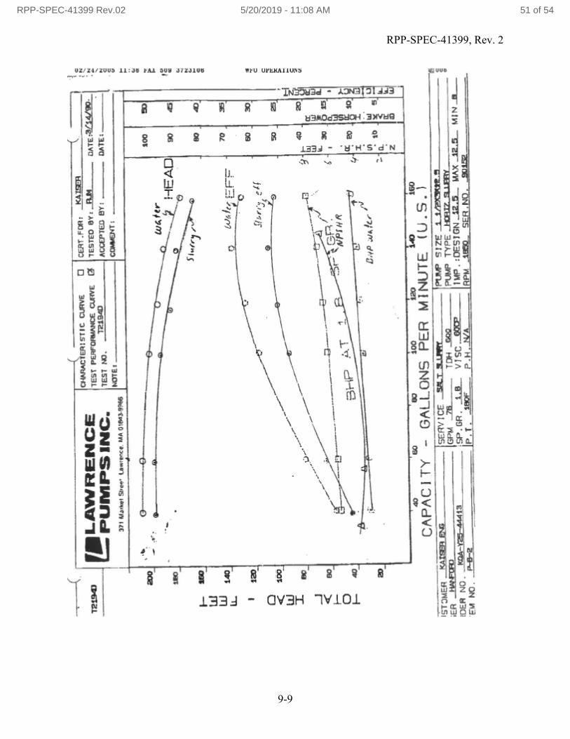
RPP-SPEC-41399, Rev. 2
9-9
(_____-
IU4A1iEA2STIt
CSJRVE 0 lCET.Foft: ._!SA
LAW PENCE
I1EST
PEIOThM14CE C
I..UVE (
I 1ESTEO BY:
OATE3IWSO
PUIWIPS INC.
lEst no.
JACCEPTED 0?: ______
______
ItJOTEs
371 &lath,t Slve.. ta*r.nce. MA OIMS-9P66
I I
H2W
w 122
0 <100
w00
—J <80
H
-
0 I—
40
200
WAler
HEAD
70
SZL.fl.t et!
--
Sr 2—
HR
WA
aI- 2
4O
20';
aLii
W
Li
/
-
asI
I
420
S0
I. LA
Lii
iL
-ID XSP-
C
it
•
z
U
C C V I- C- a C,
IC C C- p.:
C- I- C a C C C 4,
40
80
00
200
220
14)
160
CAPACITY - GALLONS PER MiNUTE (U.S.)
i5T3P4C
CRV!CE -ZttZJ-ML.__ITRPZC I tfryadt5
ER
(GPM
Th
TDH Q_
2*JMP PiPE JOW' aLy
DER NO. _K_dth44&3
'SP.GR. A& VISCSP
IMP. :OES1GNS._ MAX iL&. MIN •
NO P02
IF'.T.
Qf
P.H. N/A
PM S. SEMi-JO. ais
RPP-SPEC-41399 Rev.02 5/20/2019 - 11:08 AM 51 of 54

RPP-SPEC-41399, Rev. 2
9-10
-
1219&
w2a
0 <175
w I1-
-J H C
-- -
-
IaPrns1u; cUIVE
DTCWT.ron:
C
LAWRENCE
Imsi pc
n$fl4r
I TESTED fly: ________
_______
K
c-.. eunips inc.
lEST No.
W19E
J ACCEPTED BY: ____- DATE:_______
K C CINOTE.
ICOM*NT:
_______________
III MA,l tfeØ.. tar'.rci, MA 01M3.fltS
I I
--
________
C.
HEAD W4
C,C
-.
C.
-J N C.
260 C
C a
p I t'-
IC
SOD
• I- uJ
.6o
I
a
C I
so
go
iso__ CAPACITY - GALLONS FER MINUTE (U.S.) ________
ST.IER _S_fl_______ -
59W ICE ats t
-- Pt*F S IZE 4 4
-ER
t2_______________ -- 6PM 2fl___ TOH -_____ PUMP TYPE J17 .q
-____
___
DEI PlO. JcQAY4AJL
9'.GR. 1-
VISC._
TPP.:DESIGN ¶W
MAX 429
MIN .
RPP-SPEC-41399 Rev.02 5/20/2019 - 11:08 AM 52 of 54

RPP-SPEC-41399, Rev. 2
9-11
[!LAWRENCE
PUMPS INC
371
M.rI..1 $ice.I. latact. M.OIs4a4%6
w 0 w 1200
—J <1250
I—
-
0
100
400
• wa
0
70
60
0
S.
'EFF
—'3-
_0
40
cc'/
Ui
W
-t4f'r'' 7so
.,
U109
20
.-n.
I
ii
C p.
.p. S U
IC, C C C. p.
C. C a I C C I
I -Ck_____
-
u1
laJ
I UI
H
•t xto-
3-i ATE1
_____ -
80
90
120
550
S)
220
CAPACITY -GALLONS PER MINUTE_(U.S.)_________
.S7C4CR
IA
PC
ISERV ICE _stsi.
- --
mjs,qp size _tjiup.s-.______________
LA Ji___- -
6PM ..J&____ TOH .o -
PUMP TYPE
ai_______________
CER NO. _AY444i____
SP.GR. IS
vist..
- Hr. :OESIGt&J2._ MAX...a&. MINS
EMNO. Pt2
P.T.
F
P.H.liLA-__ RPM ____ SER.NO.
_____
on 0
cEpT.rcx: ___________
PEPFOPIMNCE C&#VE (3
TESTED DY: _________ DATE VM1L
ML _____________- ACCEPTED DY: _______ DAlE: _______
____________________
COeSIDITt ______________--______
t—iAfl
tala+e...
RPP-SPEC-41399 Rev.02 5/20/2019 - 11:08 AM 53 of 54

RPP-SPEC-41399, Rev. 2
9-12
___
LAWRENCE
PUMPS INC.
37* MvktI Stint. tew,00ct, MA 019434%6
0-
--C.
523
I- w w I.L
0 C w I -J
F-0 I-
cHARA&..jflSlIC CIRVE
El C8T.FC*: J~M_
____-
TEST PEREOM4ANCE CLMVE
1 7ESTEO
RJ4 - VAlE ,fl4/W)
TEST IC.
ACCPTED DY:
tAlE: _______
__________ C3S€UT: ____________
__
I I
ISi q rr,
EFF
__O tt4/e,-
S.1
O
S
C.
CO 407
I
33
C tI
U
60
80
120
iS
LID
LW
CAPACITY - GALLONS PER_MiNUTE (U.S.)
SCRV ICE
T
-_ -- PUS' SIZE ssw
R
6PM S-_-._
TOM -SGQ___--_ PUMP 1YP wn iw.
-__________
)ER NO. Jrj-â44i3
SP.GR. SS. VI5C.
IMP. ?DESIGN.J2S MAX ____ MDI___
RPP-SPEC-41399 Rev.02 5/20/2019 - 11:08 AM 54 of 54