DATA FILTERING OF 5-AXIS INERTIAL MEASUREMENT UNIT ...
24
DATA FILTERING OF 5-AXIS INERTIAL MEASUREMENT UNIT USING KALMAN FILTER NUR SYAZWANI BINTI SAMSUDIN Report submitted in partial fulfilment of the requirements for the award of the degree of Bachelor of Mechatronics Engineering Faculty of Manufacturing Engineering UNIVERSITY MALAYSIA PAHANG JUNE 2013
Transcript of DATA FILTERING OF 5-AXIS INERTIAL MEASUREMENT UNIT ...
DATA FILTERING OF 5-AXIS INERTIAL MEASUREMENT UNIT USING
KALMAN FILTER
NUR SYAZWANI BINTI SAMSUDIN
Report submitted in partial fulfilment of the requirements
for the award of the degree of
Bachelor of Mechatronics Engineering
Faculty of Manufacturing Engineering
UNIVERSITY MALAYSIA PAHANG
JUNE 2013

vi
ABSTRACT
This thesis has the purpose to design and develop data filtering of 5-axis Inertial
Measurement Unit (IMU) using Kalman Filter. This project endeavour to verify that
the data from 5DOF IMU can be filtered using Kalman Filter method so that it can be
used as an algorithm in motion alignment. The IMU consists of 2-axis of gyroscopes
and 3-axis of accelerometer. The Kalman filter is a set of mathematical equations that
provides an efficient computational (recursive) means to estimate the state of a process,
in a way that minimizes the mean of the squared error. The main contribution of these
algorithms is the in-motion alignment approach with unknown initial conditions. This
study explores the use of Kalman filtering of measurements from an inertial
measurement unit (IMU) to provide information on the orientation. The performances
of each filter are evaluated in terms of the roll, pitch, and yaw angles. In this thesis, I
had made an entire required analysis, design circuit, output and input data measurement
and other important parameters to develop the data filtering of 5-axis IMU that can be
implemented by using Kalman filter method. Simulation with constructed data has been
done to verify the algorithm. Also the sensor errors and their effects are discussed.
Furthermore the strategy for calibration, initialization and alignment for the system is
proposed. On the other hand, this thesis is aim to provide objective and scope of the
research, the literature review study, research methodology, and fabrication process
with result analysis and conclusion as part requirement in submitted the thesis to FYP
supervisor.
vii
ABSTRAK
Tesis ini bertujuan untuk merekabentuk dan membangunkan data penapisan Unit
Pengukuran inersia 5-paksi (IMU) menggunakan kaedah Kalman Filter. Projek ini
berusaha untuk mengesahkan bahawa data dari 5DOF IMU boleh ditapis menggunakan
kaedah Kalman Filter supaya ia boleh digunakan sebagai satu algoritma dalam jajaran
gerakan. IMU ini terdiri daripada 2-paksi giroskop dan 3-paksi pecutan. Penapis
Kalman adalah satu set persamaan matematik yang menyediakan pengiraan cekap
(rekursi) bermaksud untuk menganggarkan keadaan proses, dengan cara yang
meminimumkan min ralat kuasa dua. Sumbangan utama algoritma ini adalah sejajar
dengan pendekatan dalam gerakan dengan syarat awal tidak diketahui. Kajian ini
meneroka penggunaan Kalman penapisan ukuran dari satu unit ukuran inersia (IMU)
untuk memberi maklumat mengenai orientasi. Prestasi setiap penapis dinilai dari segi
daftar, padang, dan sudut rewang. Dalam tesis ini, saya telah membuat keseluruhan
analisis yang diperlukan, reka bentuk litar, output dan pengukuran data input dan
parameter lain yang penting untuk membangunkan data penapisan IMU 5-paksi yang
boleh dilaksanakan dengan menggunakan kaedah penapis Kalman. Simulasi dengan
data yang dibina telah dilakukan untuk mengesahkan algoritma. Kesilapan sensor dan
kesannya juga turut dibincangkan. Tambahan pula strategi untuk penentukuran,
pengawalan dan penyelarasan untuk sistem turut dicadangkan. Selain daripada itu,
karya ini adalah bertujuan untuk menyediakan objektif dan skop penyelidikan, kajian
kajian literatur, kaedah penyelidikan, dan proses fabrikasi dengan hasil analisis dan
kesimpulan sebagai keperluan bahagian dalam mengemukakan tesis kepada penyelia
projek sarjana muda.
viii
TABLE OF CONTENTS
SUPERVISOR’S DECLARATION .............................................................................. ii
STUDENT’S DECLARATION .................................................................................... iii
DEDICATION ............................................................................................................... iv
ACKNOWLEDGEMENT .............................................................................................. v
ABSTRACT .................................................................................................................... vi
ABSTRAK ..................................................................................................................... vii
TABLE OF CONTENTS ........................................................................................... viii
LIST OF TABLES ......................................................................................................... xi
LIST OF FIGURES ...................................................................................................... xii
LIST OF SYMBOLS .................................................................................................. xiii
LIST OF ABBREVIATIONS ...................................................................................... xv
CHAPTER 1 INTRODUCTION
1.1 INTRODUCTION.............................................................................................. 1
1.2 PROBLEM STATEMENT ................................................................................ 2
1.3 PROJECT OBJECTIVES .................................................................................. 3
1.4 SCOPE OF THE PROJECT............................................................................... 4
CHAPTER 2 LITERATURE REVIEW
2.0 INTRODUCTION .............................................................................................. 5
2.1 NAVIGATION .................................................................................................. 5
2.2 INERTIAL NAVIGATION SYSTEM .............................................................. 6
2.3 TYPES OF INERTIAL NAVIGATION SYSTEM ........................................... 7
2.3.1 Strap down Inertial Navigation System .................................................. 7
2.3.2 Gimballed System .................................................................................. 9
2.4 COORDINATE SYSTEM ............................................................................... 11
2.5 EULER ANGLE TRANSFORMATION ........................................................ 12
2.6 QUATERNIONS ............................................................................................. 13
2.6.1 Rotation Operation with Quaternion ................................................... 17
2.6.2 Quaternion Calculation from Gyro Data ............................................. 17
ix
2.6.3 Orientation Tracking Using Quaternion Multiplication ...................... 18
CHAPTER 3 RESEARCH AND METHODOLOGY
3.1 INTRODUCTION............................................................................................ 20
3.2 FLOW CHART ................................................................................................ 21
3.3 SIMULATION OF THE CORRECTION ALGORITHM .............................. 22
3.4 TOOLS FOR SIMULATION AND DATA ANALYSIS ................................ 23
3.5 ORIENTATION DETERMINATIONS IN 3D SPACE .................................. 23
3.6 KALMAN FILTERING................................................................................... 24
3.7 SIGNAL MODELING ..................................................................................... 25
3.8 SENSOR FUSION ........................................................................................... 25
3.9 MICROELECTROMECHANICAL SYSTEMS (MEMS).............................. 26
3.10 INERTIAL MEASUREMENT UNIT (IMU) .................................................. 26
3.10.1 Gyroscope ........................................................................................... 27
3.10.2 Accelerometer ..................................................................................... 28
3.11 ARDUINO UNO R3 ........................................................................................ 28
CHAPTER 4 RESULT AND ANALYSIS
4.1 INTRODUCTION............................................................................................ 30
4.2 TEMPERATURE EFFECTS ON GYROSCOPE……………………………30
4.3 DATA FILTERING OF 5-AXIS IMU SENSOR ............................................ 34
CHAPTER 5 CONCLUSION AND RECOMMENDATION
5.1 CONCLUSION ................................................................................................ 37
5.2 RECOMMENDATION ................................................................................... 38
REFERENCES .............................................................................................................. 39
APPENDIX A ................................................................................................................ 42
APPENDIX B ................................................................................................................ 45
APPENDIX C ................................................................................................................ 51
APPENDIX D ................................................................................................................ 52
APPENDIX E ................................................................................................................ 53

x
APPENDIX F ................................................................................................................ 54
APPENDIX G ................................................................................................................ 55

xi
LIST OF TABLE
Table 3.1 Essential Kalman Filter Equations……………………………………25

xii
LIST OF FIGURES
Figure 1.1 Initial IMU sensor coordinate axes ............................................................ 1 Figure 1.2 An IMU sensor measures linear acceleration and orientation ................... 2 Figure 2.1 Inertial Navigation System ........................................................................ 6
Figure 2.2 Strapdown inertial navigation algorithm ................................................... 8 Figure 2.3 A flow chart of a strap-down INS which takes acceleration and
rotation rates from the IMU and procedures position, velocity,
and attitude of the system………………………………………………..8
Figure 2.4 Strap down INS building blocks................................................................ 9
Figure 2.5 A gimballed IMU .................................................................................... 10
Figure 2.6 Gimballed inertial platform ..................................................................... 10
Figure 2.7 The Geodetic Coordinate System ............................................................ 11 Figure 2.8 Euler Angle Coordinate Rotations ........................................................... 12
Figure 2.9 Rotation with quaternion ......................................................................... 13
Figure 2.10 Orientation tracking using quaternion multiplication .............................. 18
Figure 3.1 Project Flow Chart ................................................................................... 21
Figure 3.2 Block diagram of a digital compass developing ...................................... 22
Figure 3.3 IMU 5 Degrees of Freedom ..................................................................... 26
Figure 3.4 Arduino Uno R3 Front ............................................................................. 29
Figure 3.5 Arduino Uno R3 Back ............................................................................. 29
Figure 4.1 X-Axis Zero g Bias vs. Temperature – Eight Parts Soldered to PCB ..... 31
Figure 4.3 Z-Axis Zero g Bias vs. Temperature – Eight Parts Soldered to PCB ...... 32
Figure 4.4 X-Axis Sensitivity vs. Temperature – Eight Parts Soldered to PCB ....... 32
Figure 4.6 Z-Axis Sensitivity vs. Temperature – Eight Parts Soldered to PCB ....... 33
Figure 4.7 Axes of Acceleration Sensitivity; Corresponding Output Voltage
Increases When Accelerated Along the Sensitive Axis .......................... 34
Figure 4.8 Sensor output before filter ....................................................................... 34
Figure 4.9 Sensor output after filtered using Kalman filter ...................................... 35
Figure 4.10 IMU Sensor output before and after filtered in x-axis ............................ 35
Figure 4.11 IMU Sensor output before and after filtered in y-axis ............................ 36
Figure 4.12 IMU Sensor output before and after filtered in z-axis ............................. 36

xiii
LIST OF SYMBOLS
Depth
Pressure
Water density
Gravitational acceleration
Roll
Pitch
Yaw
Velocity
World coordinates system
Body-fixed coordinates system
Phi
Psi
Theta
Force
Mass
Acceleration
Unit of quaternion
Magnitude of rotation
Normalized axis of rotation
Measurement sensitivity matrix or observation matrix
( ) Predicted measurement
Kalman gain
( ) Predicted or a priori value of estimation covariance
( ) Corrected or a posteriori value of estimation covariance
Covariance of dynamic disturbance noise
Covariance of sensor noise or measurement uncertainty

xiv
( ) Predicted or a priori value of the estimated state vector
( ) Corrected or a posterioroi value of the estimated state vector
Measurement vector or observation vector

xv
LIST OF ABBREVIATION
IMU Inertial Measurement Unit
5DOF 5 Degree of Freedom
KF Kalman Filter
INS Inertial Navigation System
Nav Navigation
AHRS Attitude and heading reference system

CHAPTER 1
INTRODUCTION
1.1 INTRODUCTION
The effectiveness of navigation and controls of an air vehicle are highly
dependent on the degree of precision of the on-board inertial measurement unit (IMU)
(Shiau, Huang and Chang, 2012). The IMU is a single unit in the electronics module
which collects angular velocity and linear acceleration data which is sent to the main
processor (IMU, http://www.ssl.umd.edu/projects/RangerNBV/thesis/2-4-1.htm, 2013).
The sensors in the IMU are two rate gyros and three accelerometers. With perfect gyro
measurements, the estimate of the orientation could be determined quite accurately;
however, using real sensors, the error in the estimate grows with time due to
quantization, integration, and sensor errors (Kim and Golnaraghit, 2004).
Figure 1.1: Initial IMU sensor coordinate axes [7]

2
An IMU works by detecting the current rate of acceleration, as well as it changes
in rotational attributes, including pitch, roll and yaw. This data is then fed into a
computer, which calculates the current speed and position, given a known initial speed
and position (Hazry, Sofian, and Zul Azfar, 2012).
Figure 1.2: An IMU sensor measures linear acceleration and orientation [26]
IMU available in market now are in various types and shape. So, user can select
what type, size and shape. The IMU can be selected from its degrees of freedom (DOF)
that being developed by manufacturer. For five DOF, the sensors configurations are
three accelerometers and two gyroscopes that measure pitch and roll.
1.2 PROBLEM STATEMENT
An inertial measurement unit, or IMU, is the main component of inertial
guidance systems used in air space, and watercraft, including guided missiles. Driven
by their low cost and small size, MEMS inertial sensors have been used to produce low
cost INS that can be widely adopted in several navigation applications (Elkhidir,
Shuhimi, Musa and Satti, 2011). An IMU works by sensing motion including the type,
3
rate, and direction of that motion using a combination of accelerometers and gyroscopes
(Hazry, Sofian and Zul Azfar, 2012). Therefore, the noise level at the output of MEMS-
based inertial sensors must be reduced and the sensor errors separate from motion
dynamics prior to processing their measurements by the KF module. One possible way
of reducing high-frequency sensor noise is to use a low-pass filter. However, discrete
low-pass filters result in inherent time delays when applied to system in real time, which
could reduce the stability of the system (Angelosanto, 2008).
Low-pass filters also do not address the issues of inaccurate or unavailable
measurements. In inertial navigation systems, two to three integrations are required to
get from sensor outputs to a position solution. This is the major disadvantage of dead
reckoning and inertial navigation; the fact that one or more integrations are required to
convert sensor outputs to a position solution means that errors in sensor outputs lead to
position errors that grow with time (Demoz Gebre-Egziabher, 2010). In this project, an
inertial navigation system based on low-cost IMU sensor will be developed.
1.3 PROJECT OBJECTIVES
This project is intended to design and develop a data filtering of 5-axis IMU
using Kalman Filter. The IMU use is low cost, high integrity and their board enables to
easily incorporate roll, pitch, and tilt measurements for navigation application. The
5DOF-IMU data filtering is based on the Kalman filter method which is from a
mathematical concept with a deep relationship with the foundations of algebra and
number theory. In summary, the objectives of this project:
1. The main task of this project is to design and develop data filtering of 5-axis
Inertial Measurement Unit (IMU) using Kalman Filter.
2. From all of the method used, verify the 5-axis inertial measurement unit can
be filtered using Kalman Filter method.

4
1.4 SCOPE OF THE PROJECT
The main task of this work is to analyse several method in filtering data of 5-
axis IMU but focusing on Kalman Filter method. A comparison between the results
obtained will be performed on the basis of accuracy, complexity of the algorithm and
ease of implementation on the embedded system. SIMULINK and MATLAB also will
be used in this task to promote an understanding of the real system. In summary, the
scope of this project is:
1. Design and modelling data filtering of 5-axis IMU using Kalman Filter via
MATLAB.
2. In this project, programming and real circuit for sensor setup also been
developed.
CHAPTER 2
LITERATURE REVIEW
2.0 INTRODUCTION
This chapter will focused on the historical background for the data filtering of 5-
axis Inertial Measurement Unit (IMU) using Kalman Filter and other method involved
in this study. This chapter deal with the previous work done which are reviewed from
journal, website, books and other related resources. In this chapter, the basics of inertial
navigation system and comparison between gimballed system and an underwater strap
down inertial navigation is been covered.
2.1 NAVIGATION
Navigation can be defined as determination of a physical body's position and
velocity relative to some reference coordinate frame (Anwar, 2010). A simple one
dimensional example of navigation is determining the position and speed of a train
between two points on a track. The basic concept of navigation is latitude and
longitude. All navigation techniques can be viewed as processes in which the
mathematical operation of integration is performed on the sensor outputs to yield
position (Gebre-Egziabher, 2004). Navigation systems need different kinds of
information: position from global or relative coordinates, as well as direction which is

6
an orientation angles (Damian, 2011). This information is provided by the sensors
whose data must be fused.
2.2 INERTIAL NAVIGATION SYSTEM
An inertial navigation system (INS) continuously calculates the position,
orientation, and velocity (direction and speed of movement) of a moving object without
the need for external references (Anwar, 2010). The calculation can be performing by
using a computer, motion sensors (accelerometers) and rotation sensors (gyroscope) by
using computer.
A block diagram in figure 2.1 shows an inertial measurement unit (IMU)
combined with navigation equations to form an inertial navigation system (INS). A
handful of useful tricks have been used to align blocks and arrows nicely. Hard coding
coordinates has been avoided as much as possible.
Figure 2.1: Inertial Navigation System [20]
The INS consists of 3-axis gyroscopes which give the system computer the roll,
pitch and yaw rates about the body axes. Inertial navigation is a self-contained
navigation technique in which measurements provided by accelerometers and

7
gyroscopes are used to track the position and orientation of an object relative to a
known starting point, orientation and velocity (Woodman, 2007).
An INS consists of the following:
An IMU
Instrument support electronics
Navigation computers (one or more) calculate the gravitational acceleration
(not measured by accelerometer) and doubly integrate the net acceleration to
maintain an estimate of the position of the host vehicle
2.3 TYPES OF INERTIAL NAVIGATION SYSTEM
There are many different designs of INS with different performance,
characteristics, but there are two types of inertial navigation system that can be
compared. Their difference in mechanical design gives result in different requirements
of the electronic and software. Inertial navigation is a self-contained navigation
technique in which measurements provided by accelerometers and gyroscopes are used
to track the position and orientation of an object relative to a known starting point,
orientation and velocity (Woodman, 2007). Inertial measurement units (IMUs)
typically contain three orthogonal rate-gyroscopes and three orthogonal accelerometers,
measuring angular velocity and linear acceleration respectively.
2.3.1 Strapdown Inertial Navigation System
Traditionally, the general displacement of a rigid body in a strap down inertial
navigation system (INS) are modeled and analyzed separately, i.e., the direction cosine
matrix or quaternion for the analysis of rotation and translation analysis for vector. The
strap down INS emerged about half a century ago as an alternative in which the gyro
and accelerometer triads are directly mounted on the vehicle (Wu, Hu, Wu and Hu,
8
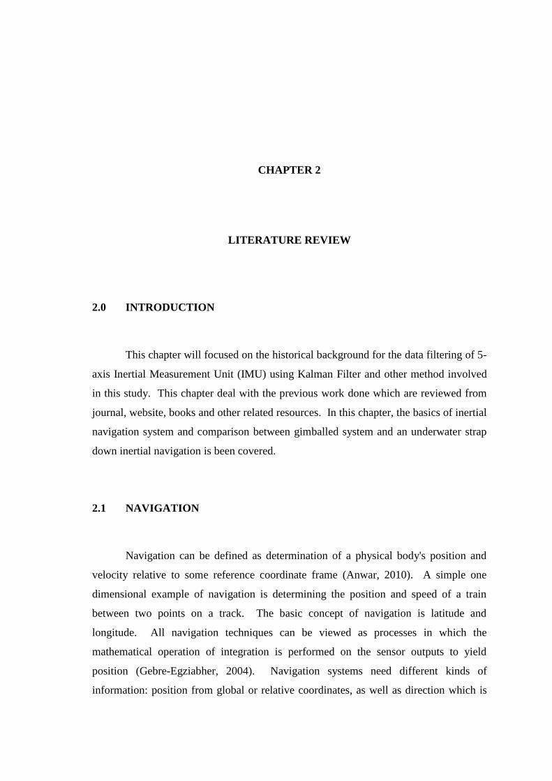
2004). The gyro outputs are used to maintain a digital reference frame, into which the
specific force measurements from accelerometer triads are resolved and then double
integrated to acquire velocity and position. The choice of the reference frame usually
depends on the convenience of application.
Inertial sensors for strap down systems experience much higher rotation as
compared to their gimballed counterparts. Rotation introduces error mechanisms that
require attitude rate-dependent error compensation (Woodman, 2007).
Figure 2.2: Strapdown inertial navigation algorithm [21]
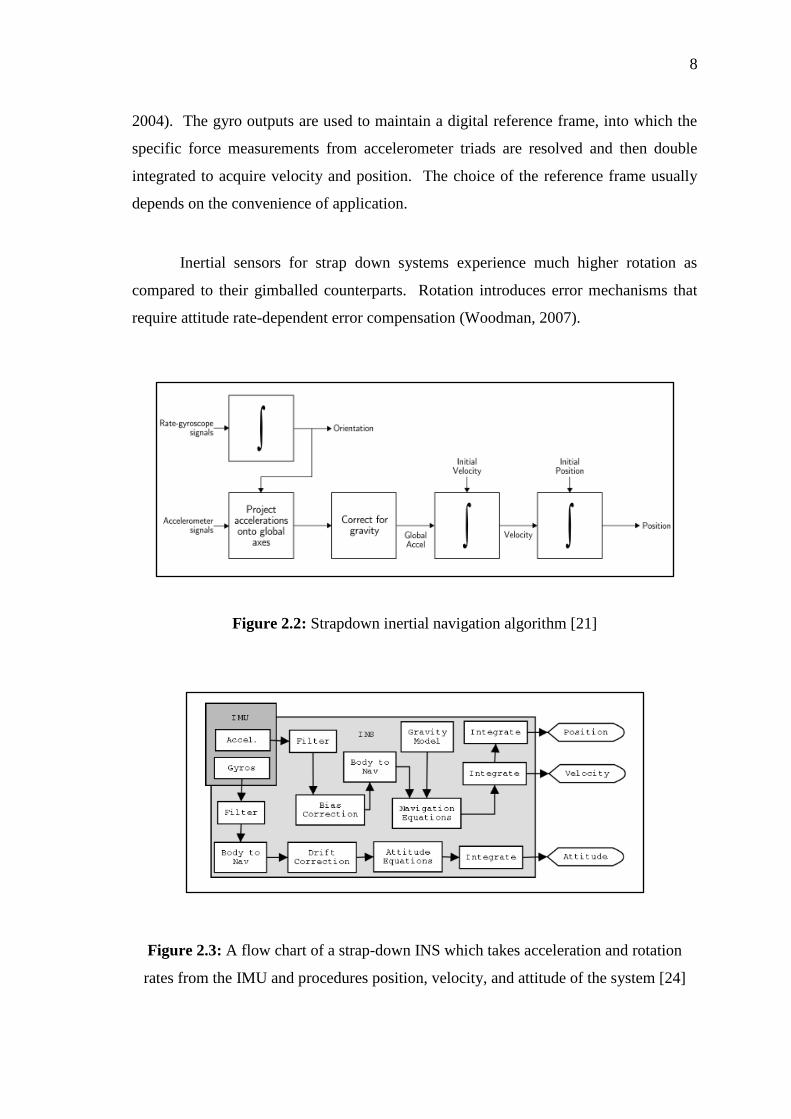
Figure 2.3: A flow chart of a strap-down INS which takes acceleration and rotation
rates from the IMU and procedures position, velocity, and attitude of the system [24]

9
In strap down systems the inertial sensors are mounted rigidly onto the device,
and therefore output quantities measured in the body frame rather than the global frame.
To keep track of orientation the signals from the rate gyroscopes are ‘integrated’. To
track position the three accelerometer signals are resolved into global coordinates using
the known orientation, as determined by the integration of the gyro signals. The global
acceleration signals are then integrated as in the stable platform algorithm.
Figure 2.4: Strap down INS building blocks [16]
The advantage of a strap down system is the cost. Compared to gimbal, the cost
of replicating software is relatively small. However, cost for calibrating and testing
requires a precision rate table. Since there is no isolation from the body's rotation, to
limit the accuracy, gyros with high range have to be chosen.
2.3.2 Gimballed System
The first type of INS developed was a gimballed system. The accelerometers
are mounted on a motorized gimballed platform which was always kept aligned with the
navigation frame (Woodman, 2007) (Walchko and Dr Mason, 2002). Pickups are
located on the outer and inner gimbals which keep track of the attitude of the stabilized
platform relative to the vehicle on which the INS is mounted.

10
Figure 2.5: A gimballed IMU [12]
Figure 2.6: Gimballed inertial platform [17]
There is an advantage by using a gimballed system compared to a strap down
system. Gimballed system eliminates many rate-dependant sensor errors and allows for
higher accuracy sensors (Anwar, 2010). This might be happen from the isolation of the
inertial sensors from high rates of. On the other hand, the complexity of the mechanical
design which is bounded with problem like friction and reliability become a
disadvantage of using this system. Bigger in size and higher in cost of the needs of
motors and control electronics is disadvantages of gimballed system use.

11
2.4 COORDINATE SYSTEM
The relationships between data expressed can be considered in two different
coordinate systems:
The world coordinate system is fixed in inertial space. The origin of this
coordinate system is denoted Xw.
The body-fixed coordinate system is rigidly attached to the object whose
attitude we would like to describe. The origin of this coordinate system is
denoted Xb.
Depending on application, the coordinate system could be defined in a different way.
Some application uses left hand coordinate system.
Figure 2.7: The Geodetic Coordinate System [5]

12
2.5 EULER ANGLE TRANSFORMATION
A rotation matrix can be built from three matrices representing rotation around
the axes of the local coordinate system, where each rotation is defined by an angle
(Anwar, 2010). Some authors refer the angles as yaw, pitch and roll. The order of
multiplication of the matrices is important since matrix multiplication is not
commutative. A rotational coordinate transformation delivers different column matrices
for the same vector x.
Rotation about the x-axis from CS:
Rotation about the y-axis from CS:
Rotation about the z-axis from CS:
Figure 2.8: Euler Angle Coordinate Rotations [33]
[
] (2-1)

13
[
] (2-2)
[
] (2-3)
The rotation about the y-axis has a different sign pattern. Compound matrix rotations
about three axes depend on the sequence.
2.6 QUATERNIONS
Quaternion was first introduced by Sir W. R. Hamilton in 1843. Quaternion is a
relationship with a foundation of algebra and number of theory. A quaternion can be
thought of as a vector with four components, as a composite of a scalar and an ordinary
vector, or as a complex number with three different imaginary parts (Berthold, 1986).
Quaternions (as a mathematical method) is an extension, or improvement, of Cartesian
geometry, in which the artifices of coordinate axes, &c., are got rid of, all directions in
space being treated on precisely the same terms (Peter Guthrie Tait, 1886).
Furthermore, it is easily to construct the corresponding quaternion from a given axis and
angle, and conversely read off the axis and the angle from a given quaternion.
Figure 2.9: Rotation with quaternion [16]