DAB+ Digital Radio RF Transmission Planning
58
ASBU / WorldDAB - DAB+ Workshop, Amman, Jordan 23-24 August 2017 DAB+ Digital Radio RF Transmission Planning Dr Les Sabel, WorldDAB Technical Committee
Transcript of DAB+ Digital Radio RF Transmission Planning

ASBU / WorldDAB - DAB+ Workshop, Amman, Jordan 23-24 August 2017
DAB+ Digital Radio RF Transmission Planning
Dr Les Sabel, WorldDAB Technical Committee

1
• Planning levels – mainly ITU / EBU but each country has its own slight
variations
• SFN operation
- Why is this good/useful
- Efficiency of DAB (relative to FM)
• Interference issues
- coordination
• Design process
• Coverage examples
RF Planning

2
Capacity and coverage requirements
RF Coverage – Requirements
How many services (now and later)
• Defines how much spectrum is needed
• E.g. Sydney uses 3 ensembles (5.136MHz) for approx 63 services
Number of services in each Region or Licence Area?
Service capacity includes both audio and PAD
How much of the population must be covered
• Define minimum coverage requirements
• Significant for difficult terrain and large areas
• Increases to (near) 100% of the country as the deployment process approaches
Analogue Switch Off (ASO)

3
Spectrum Requirements
RF Coverage – Requirements
What VHF band III capacity is available?
• Which channels?
Multiple Frequency Network planning – cellular design
• Power levels are critical
• Coverage vs Co-Channel Interference (CCI)
• Adjacent Channel Interference (ACI) with other/adjacent cells / LAPs
• spectrum reuse
• typical cellular design requires >4 times single cell capacity dependant on
terrain and coverage requirements

4
2 DTV channels allocated
14MHz = 8 DAB channels = 8A, B, C, D, 9A, B, C, D
Transmission – Frequency plan
UK channel allotments
Australian
Band III
allocation
5
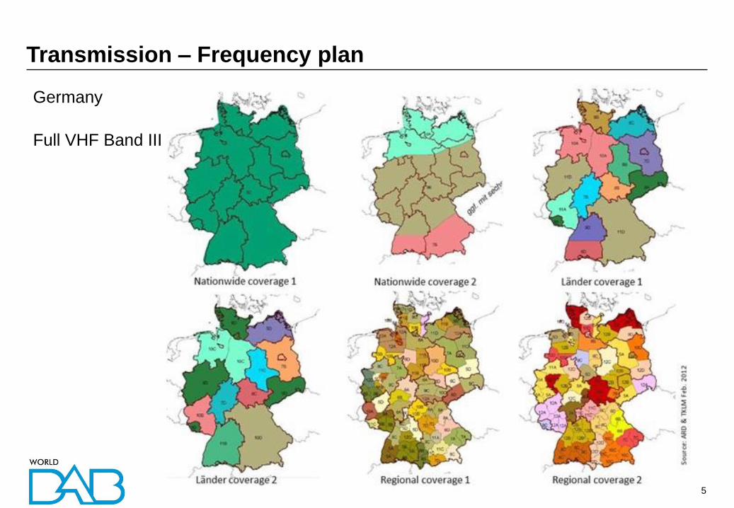
Transmission – Frequency plan
Germany
Full VHF Band III

6
Overview Signal bandwidth = 1536 carriers at 1kHz each => 1.535MHz
Channel bandwidth = 1.712 MHz
Channel edge
shoulders at -40dB
Far off adjacent
power at <-60dB
RF spectrum
Transmission

7
Transmission channels
- Line of Sight / Ricean
- Rayleigh
Transmission
The received signal is
composed of multiple signal
paths and USUALLY has no
direct line of sight
component, i.e. is a
Rayleigh channel
The received signal is
composed of multiple signal
paths and USUALLY has no
direct line of sight component,
i.e. is a Rayleigh channel

8
Australian Commercial Radio Planning targets (2017)
RF Coverage – Levels
Below 50dBuV/m is considered to provide unreliable coverage in vehicles
Some areas may receive marginal coverage but patchy coverage is unsatisfactory
> 60 dBuV/m
54 – 60 dBuV/m
50 – 54 dBuV/m
Defined by ITU / EBU but each country has its own slight variations

9
Planning Considerations
RF Planning – Tools, Methods and Standards
ITU
• BS.1660 -includes guidelines for planning but is now quite old
EBU
• Recommendation R 138 - DIGITAL RADIO DISTRIBUTION IN EUROPE
• Recommendation 2: Immediate deployment be done using DAB transmission
as defined in ETSI EN 300 401 with DAB+ services as defined in ETSI TS 102
563 for digital radio broadcasting in VHF Band III;
• TR 021 - TECHNICAL BASES FOR T-DAB SERVICES NETWORK PLANNING
AND COMPATIBILITY WITH EXISTING BROADCASTING SERVICES
• Frequencies and protection
• TR 025 - REPORT ON FREQUENCY AND NETWORK PLANNING
PARAMETERS RELATED TO DAB+
• Receiver C/N values
• BPN003 - TECHNICAL BASES FOR T-DAB SERVICES NETWORK PLANNING
AND COMPATIBILITY WITH EXISTING BROADCASTING SERVICES
• Transmission planning levels, receiver C/N and SFN operation and gain
Be cautious
Theory does not always = practice!
Propagation modelling should
always be followed up with in field
measurements to tune models to
obtain the most accrate results
Science is improving predictions
and planning process
EBU Broadcast Network Planning
group is reworking the EBU DAB+
planning guidelines given recent
measurements and results

10
Multi-Frequency Networks and Single Frequency Networks
RF Planning - Network Types
• Single frequency network.
• Multiple transmitters
• Can be any combination of high, medium and
low power transmitters
MFN
e.g. Main Tx and 2 Gap Fillers SFN
e.g. Main Tx and 2 Gap Fillers
SFNs are a more efficient
use of spectrum
11
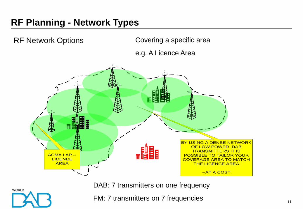
RF Network Options
RF Planning - Network Types
Covering a specific area
e.g. A Licence Area
DAB: 7 transmitters on one frequency
FM: 7 transmitters on 7 frequencies

12
SFN coverage in Sale, Victoria, Australia
SFN example
7 transmitters to cover 200km ranging from 1 to 5kW each

13
Link Fed Repeaters
RF Planning - Network Types
The repeater is fed an ETI/EDI signal via a link
- Microwave
- Telco landline (fibre, dedicated or shared, diversity)
Telco Link
Microwave link

14
On Channel Repeater
RF Planning - Network Types
Receives the signal off-air and then retransmits on the same frequency
Echo cancelling techniques allow repeaters to be built which can re-transmit on the
same frequency
For FM the repeater
must translate the
received signal to
another frequency

15
Licence areas - Northern NSW example
RF Planning – Multi-Frequency Network

16
Interference between Sweden and Germany and Denmark
Cross border coordination

17
Interference Considerations
RF Planning – Tools, Methods and Standards
ACMA defined Protection Ratios
Unwanted
Wanted CCI Protection Ratio =12dB
ACI Protection Ratio = -40dB
Affects the re-use distance in
multi-frequency networks
Higher value results in more
conservative planning
Affects the allowed impact on adjacent
channel transmissions in multi-frequency
networks
More negative value provides less protection

18
Local transmission punching a coverage hole into a wide area transmission
ACI coverage hole punching

19
The Design Cycle
RF Planning – Levels, methods and standards
• The first loop is the hardest
• A test transmission will provide
the best learning experience
• Use the initial system results
to help design future systems
Requirements
Model
Design Build
Verify
adjust
test
formalise
adjust
science
details
publish
Engineering collaboration helps
minimise the system design and
deployment effort and
maximises benefits to listeners
and in turn broadcaster returns

20
The Design Cycle – Coverage Modelling
RF Planning – Levels, methods and standards
• Model coverage then interference
• Main high power site first, then in-fills/repeaters
• Use antenna pattern HRP and down tilt VRP (if required)
• Tuning the coverage model to maximise accuracy
– Cartography resolution
– propagation model
– clutter parameters
• Test transmissions at lower power will allow more accurate design through empirical
verification in the field
– At least for initial sites
– Is terrain / clutter dependant

21
The Design Cycle
RF Planning – Tools, Methods and Standards
• A cooperative and collaborative process between both
broadcasters and the regulator
• Site selection
– High sites will provide the best coverage but also the longest
distances for CCI
– Use the same sites for multiple ensembles if possible
– National and commercial coverage variations
– Collocate with VHF TV to minimise ACI issues
• Antenna selection
– Patterns, Down tilt, Gain
• higher gain = lower power costs but more initial Capex
• Antenna patterns may need to be shaped to minimise interference
– DC grounded antennas
Save Money / Make Money

22
High Power High Tower v Low Power Low Tower selections
• Higher sites will always provide greater coverage due to increased line-of-sight areas
• Terrain is the largest impact on coverage area, large buildings are equivalent to hills!
• Uneven and shadowed terrain requires increased main site power and/or increased
repeaters
RF Planning - Transmission network design considerations
Type Power
(kW ERP)
Height above
served area (m)
Best use
HPHT 20-50+ >250 wide area coverage but may experience
shadowed areas especially in the distant
coverage areas
Typical coverage radius = 30 – 80km
MPMT 5-20 50-250 undulating areas with no high transmission site
Typical coverage radius = 10 – 30km
LPLT 0.3-5 <50 local area coverage
Typical coverage radius = 2 – 10km

23
Terrain
shielding
and
undulations
Sydney
northern
beaches
RF Planning - Transmission network design considerations

24
City building shielding - Melbourne
RF Planning - Transmission network design considerations
Mt Dandenong
transmitter 45kms

25
HPHT – LPLT Cost implications
• HPHT will usually give best coverage kms2/$
• City sites can be very expensive, even for LPLT
• High population density drives prices up even for sites like water towers
• Telco towers are often too low!
• Site costs are often the largest component of Opex for main AND repeaters
• Site selection for cost optimisation is time consuming – especially for multiple
repeater sites in large cities
• The number of main HPHT sites in large cities are often limited
RF Planning - Transmission network design considerations

26
Allotment planning process
Iterate the loop until the
population coverage and CCI
requirements are met
Define transmitter sites and
parameters
Model population coverage
Model CCI
Select area frequency channel to
minimise CCI
Review
Requirements
Local / regional /
national areas
Identify population
coverage areas
Sometime cost minimisation
will require trade-offs in
coverage and/or interference
targets
ACI and self-interference will
also need to be examined
As sites are built the coverage
can be measured and the
models adjusted to maximise
accuracy as the roll-out
progresses

27
Licence areas – South Eastern Australia example
RF Planning – Multi-Frequency Network

28
Frequency Planning
• Cultural considerations - may need to deliver the same/equivalent content in different
languages for different areas
• Ensembles with ANY different content will need to use different ensemble frequencies
in an MFN configuration within CCI rules
• The terrain of each area may provide natural boundaries to facilitate more efficient
frequency re-use
• Existing use of the VHF Band III spectrum must be taken into account to ensure that
interference is within defined limits
RF Planning - Transmission network design considerations

29
Adelaide Licence Area
RF Planning - Design examples

30
Adelaide terrain viewed from the south
RF Planning - Design examples
Mt Lofty transmitter
site Adelaide CBD

31
Adelaide TV Towers at Mt Lofty
RF Planning - Design examples

32
Adelaide TV Towers at Mt Lofty
RF Planning - Design examples
80kms

33
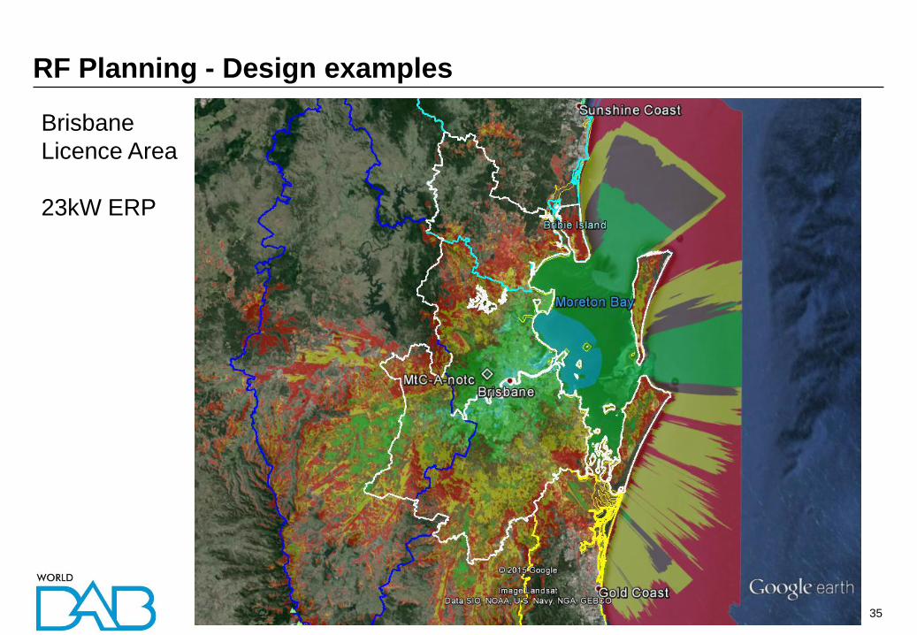
Brisbane Licence Area
RF Planning - Design examples

34
Brisbane EMAX vs. ERP
RF Planning - Design examples
1
0.9
0.8
0.7
0.6
0.5
0.4
0.3
0.2
0.1
180
0
270 90
E / Emax
BRISBANE ACMA DRCP 18 Dec 08
RF network
design must
consider
interference and
well as coverage
35
Brisbane
Licence Area
23kW ERP
RF Planning - Design examples

36
Brisbane
Licence Area
Drive test
results
RF Planning - Design examples

37
Brisbane Licence Area
Ipswich
RF Planning - Design examples

38
Brisbane Licence Area
Proposed high power option
50kW ERP
RF Planning - Design examples

39
Brisbane
Licence Area
50kW ERP
Notch removed
RF Planning - Design examples

40
Brisbane
Licence Area
23kW
With notch
RF Planning - Design examples
41
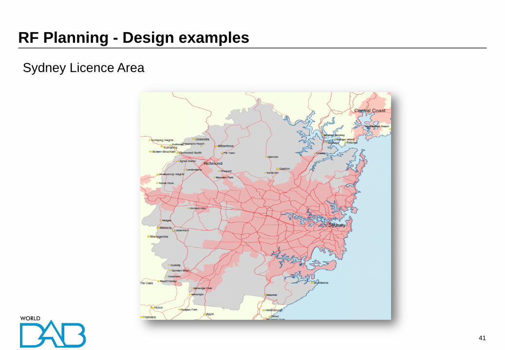
Sydney Licence Area
RF Planning - Design examples

42
Sydney Terrain viewed from the East
RF Planning - Design examples
Artarmon transmitter site

43
Sydney Terrain – looking north over Camden valley
RF Planning - Design examples

44
Sydney LAP
RF Planning - OCR Case Study
Single 50kW Tx

45
Sydney LAP
RF Planning - OCR Case Study
Single 50kW tx
50 km

46
Sydney LAP
RF Planning - OCR Case Study
Single 50kW tx
52 km

47
Sydney LAP
RF Planning - OCR Case Study
Single 50kW tx
6 repeaters
No network
gain shown
52 km

48
Artarmon main
Tx only
50kW
200m AGL
Areas of
shadowing
shown
Prediction is
optimistic due
to clutter
generalisation
RF Planning - OCR Case Study

49
Centrepoint
only
300W
125m AGL
RF Planning - OCR Case Study

50
Redfern only
300W
50m AGL
RF Planning - OCR Case Study

51
All
RF Planning - OCR Case Study

52
Sydney city centre
RF Planning - OCR Case Study
Impulse response for an
in-building receiver in
Surry Hills – 5th floor
Main Tx at Artarmon
Centrepoint repeater
Redfern repeater
53
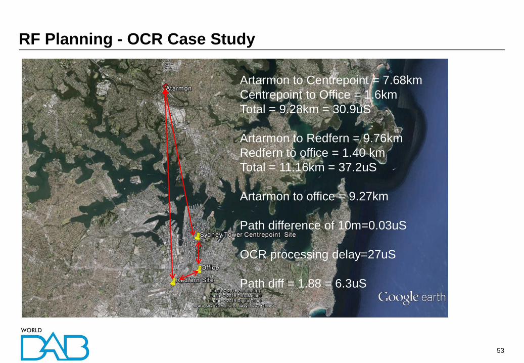
RF Planning - OCR Case Study
Artarmon to Centrepoint = 7.68km
Centrepoint to Office = 1.6km
Total = 9.28km = 30.9uS
Artarmon to Redfern = 9.76km
Redfern to office = 1.40 km
Total = 11.16km = 37.2uS
Artarmon to office = 9.27km
Path difference of 10m=0.03uS
OCR processing delay=27uS
Path diff = 1.88 = 6.3uS

54
Sydney city centre repeaters
RF Planning - OCR Case Study
Ch 9B
27uS 6.9uS = 180m error

55
Sydney city centre repeaters
RF Planning - OCR Case Study
Ch 9C
27uS 6.9uS

56
Summary – Top Tips
RF Planning - RF planning
1. Know what you want to achieve – the BIG PICTURE
2. Be Collaborative in Engineering the system – Competitive on Content
3. Work with your Regulator to ensure that all parties are considered
4. A successful rollout will require consultation with retailers, automotive etc
5. Use the design cycle to your advantage – process is important
6. RF Coverage modelling is essential
7. Beware of Co-Channel Interference and Adjacent Channel Interference
8. Plan field testing and tune your models – coverage and interference

57
Thank you
For further information, please contact:
www.worlddab.org
or