KAVOSHCOM RF Communication Circuits Lecture 1: Transmission Lines.
55
KAVOSHCOM RF Communication Circuits Dr. Fotowat-Ahmady Sharif University of Technology Fall-1391 Prepared by: Siavash Kananian & Alireza Zabetian Lecture 1: Transmission Lines
-
Upload
janice-bailey -
Category
Documents
-
view
239 -
download
1
Transcript of KAVOSHCOM RF Communication Circuits Lecture 1: Transmission Lines.

KAVOSHCOM
RF Communication Circuits
Dr. Fotowat-AhmadySharif University of TechnologyFall-1391Prepared by: Siavash Kananian & Alireza Zabetian
Lecture 1: Transmission Lines

A wave guiding structure is one that carries a signal (or power) from one point to another.
There are three common types: Transmission lines Fiber-optic guides Waveguides
Waveguiding Structures
2

Transmission Line
Has two conductors running parallel Can propagate a signal at any frequency (in theory) Becomes lossy at high frequency Can handle low or moderate amounts of power Does not have signal distortion, unless there is loss May or may not be immune to interference Does not have Ez or Hz components of the fields (TEMz)
Properties
Coaxial cable (coax)Twin lead
(shown connected to a 4:1 impedance-transforming balun)
3

Transmission Line (cont.)
CAT 5 cable(twisted pair)
The two wires of the transmission line are twisted to reduce interference and radiation from discontinuities.
4

Transmission Line (cont.)
Microstrip
h
w
er
er
w
Stripline
h
Transmission lines commonly met on printed-circuit boards
Coplanar strips
her
w w
Coplanar waveguide (CPW)
her
w
5

Transmission Line (cont.)
Transmission lines are commonly met on printed-circuit boards.
A microwave integrated circuit
Microstrip line
6

Fiber-Optic GuideProperties
Uses a dielectric rod Can propagate a signal at any frequency (in theory) Can be made very low loss Has minimal signal distortion Very immune to interference Not suitable for high power Has both Ez and Hz components of the fields
7

Fiber-Optic Guide (cont.)Two types of fiber-optic guides:
1) Single-mode fiber
2) Multi-mode fiber
Carries a single mode, as with the mode on a transmission line or waveguide. Requires the fiber diameter to be small relative to a wavelength.
Has a fiber diameter that is large relative to a wavelength. It operates on the principle of total internal reflection (critical angle effect).
8

Fiber-Optic Guide (cont.)
http://en.wikipedia.org/wiki/Optical_fiber
Higher index core region
9

Waveguides
Has a single hollow metal pipe Can propagate a signal only at high frequency: > c
The width must be at least one-half of a wavelength
Has signal distortion, even in the lossless case Immune to interference Can handle large amounts of power Has low loss (compared with a transmission line) Has either Ez or Hz component of the fields (TMz or TEz)
Properties
http://en.wikipedia.org/wiki/Waveguide_(electromagnetism) 10

Lumped circuits: resistors, capacitors, inductors
neglect time delays (phase)
account for propagation and time delays (phase change)
Transmission-Line Theory
Distributed circuit elements: transmission lines
We need transmission-line theory whenever the length of a line is significant compared with a wavelength.
11

Transmission Line
2 conductors
4 per-unit-length parameters:
C = capacitance/length [F/m]
L = inductance/length [H/m]
R = resistance/length [/m]
G = conductance/length [ /m or S/m]
Dz
12

Transmission Line (cont.)
z
,i z t
+ + + + + + +- - - - - - - - - - ,v z tx x xB
13
RDz LDz
GDz CDz
z
v(z+z,t)
+
-
v(z,t)
+
-
i(z,t) i(z+z,t)

( , )( , ) ( , ) ( , )
( , )( , ) ( , ) ( , )
i z tv z t v z z t i z t R z L z
tv z z t
i z t i z z t v z z t G z C zt
Transmission Line (cont.)
14
RDz LDz
GDz CDz
z
v(z+z,t)
+
-
v(z,t)
+
-
i(z,t) i(z+z,t)

Hence
( , ) ( , ) ( , )( , )
( , ) ( , ) ( , )( , )
v z z t v z t i z tRi z t L
z ti z z t i z t v z z t
Gv z z t Cz t
Now let Dz 0:
v iRi L
z ti v
Gv Cz t
“Telegrapher’sEquations”
TEM Transmission Line (cont.)
15

To combine these, take the derivative of the first one with
respect to z:
2
2
2
2
v i iR L
z z z t
i iR L
z t z
vR Gv C
t
v vL G C
t t
Switch the order of the derivatives.
TEM Transmission Line (cont.)
16

2 2
2 2( ) 0
v v vRG v RC LG LC
z t t
The same equation also holds for i.
Hence, we have:
2 2
2 2
v v v vR Gv C L G C
z t t t
TEM Transmission Line (cont.)
17

2
2
2( ) ( ) 0
d VRG V RC LG j V LC V
dz
2 2
2 2( ) 0
v v vRG v RC LG LC
z t t
TEM Transmission Line (cont.)
Time-Harmonic Waves:
18

Note that
= series impedance/length
2
2
2( )
d VRG V j RC LG V LC V
dz
2( ) ( )( )RG j RC LG LC R j L G j C
Z R j L
Y G j C
= parallel admittance/length
Then we can write:2
2( )
d VZY V
dz
TEM Transmission Line (cont.)
19

Let
Convention:
Solution:
2 ZY
( ) z zV z Ae Be
1/2
( )( )R j L G j C
principal square root
2
2
2( )
d VV
dzThen
TEM Transmission Line (cont.)
is called the "propagation constant."
/2jz z e
j
0, 0
attenuationcontant
phaseconstant
20

TEM Transmission Line (cont.)
0 0( ) z z j zV z V e V e e
Forward travelling wave (a wave traveling in the positive z direction):
0
0
0
( , ) Re
Re
cos
z j z j t
j z j z j t
z
v z t V e e e
V e e e e
V e t z
g0t
z0
zV e
2
g
2g
The wave “repeats” when:
Hence:
21

Phase VelocityTrack the velocity of a fixed point on the wave (a point of constant phase), e.g., the crest.
0( , ) cos( )zv z t V e t z
z
vp (phase velocity)
22

Phase Velocity (cont.)
0
constant
t z
dz
dtdz
dt
Set
Hence pv
1/2
Im ( )( )p
vR j L G j C
In expanded form:
23

Characteristic Impedance Z0
0
( )
( )
V zZ
I z
0
0
( )
( )
z
z
V z V e
I z I e
so 00
0
VZ
I
+ V+(z)-
I+ (z)
z
A wave is traveling in the positive z direction.
(Z0 is a number, not a function of z.)
24

Use Telegrapher’s Equation:
v iRi L
z t
sodV
RI j LIdz
ZI
Hence0 0
z zV e ZI e
Characteristic Impedance Z0 (cont.)
25

From this we have:
Using
We have
1/2
00
0
V Z ZZ
I Y
Y G j C
1/2
0
R j LZ
G j C
Characteristic Impedance Z0 (cont.)
Z R j L
Note: The principal branch of the square root is chosen, so that Re (Z0) > 0. 26

00
0 0
j z j j z
z z
z j zV e e
V z V e V
V e e e
e
e
0
0 cos
c
, R
os
e j t
z
z
V e t
v z t V z
z
V z
e
e t
Note:
wave in +z direction wave in -z
direction
General Case (Waves in Both Directions)
27
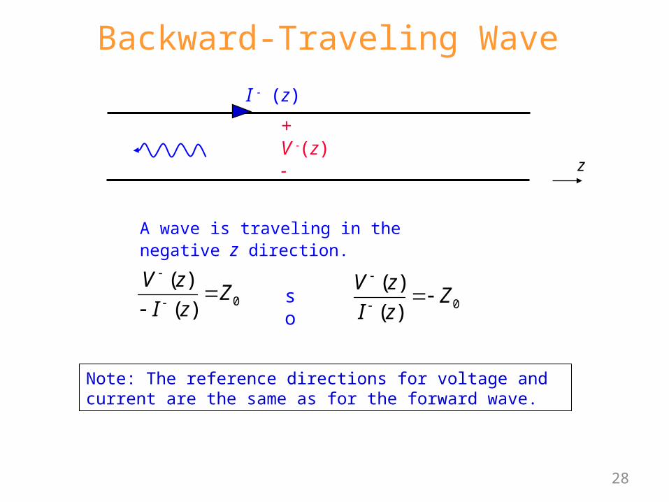
Backward-Traveling Wave
0
( )
( )
V zZ
I z
0
( )
( )
V zZ
I z
so
+ V -(z)-
I - (z)
z
A wave is traveling in the negative z direction.
Note: The reference directions for voltage and current are the same as for the forward wave.
28

General Case
0 0
0 00
( )
1( )
z z
z z
V z V e V e
I z V e V eZ
A general superposition of forward and backward traveling waves:
Most general case:
Note: The reference directions for voltage and current are the same for forward and backward waves.
29
+ V (z)-
I (z)
z

1
2
12
0
0 0
0 0
0 0
z z
z z
V z V e V e
V VI z e e
Z
j R j L G j C
R j LZ
G j
Z
C
I(z)
V(z)+- z
2mg
[m/s]pv
guided wavelength g
phase velocity vp
Summary of Basic TL formulas
30

Lossless Case0, 0R G
1/ 2
( )( )j R j L G j C
j LC
so 0
LC
1/2
0
R j LZ
G j C
0
LZ
C
1pv
LC
pv
(indep. of freq.)(real and indep. of freq.)31

Lossless Case (cont.)1
pvLC
In the medium between the two conductors is homogeneous (uniform) and is characterized by (, ), then we have that
LC
The speed of light in a dielectric medium is1
dc
Hence, we have that p dv c
The phase velocity does not depend on the frequency, and it is always the speed of light (in the material).
(proof given later)
32

0 0z zV z V e V e
Where do we assign z = 0?
The usual choice is at the load.
I(z)
V(z)+-
zZL
z = 0
Terminating impedance (load)
Ampl. of voltage wave propagating in negative z direction at z = 0.
Ampl. of voltage wave propagating in positive z direction at z = 0.
Terminated Transmission Line
Note: The length l measures distance from the load: z33

What if we know
@V V z and
0 0V V V e
z zV z V e V e
0V V e
0 0V V V e
Terminated Transmission Line (cont.)
0 0z zV z V e V e
Hence
Can we use z = - l as a reference plane?
I(z)
V(z)+-
zZL
z = 0
Terminating impedance (load)
34

( ) ( )z zV z V e V e
Terminated Transmission Line (cont.)
0 0z zV z V e V e
Compare:
Note: This is simply a change of reference plane, from z = 0 to z = -l.
I(z)
V(z)+-
zZL
z = 0
Terminating impedance (load)
35

0 0z zV z V e V e
What is V(-l )?
0 0V V e V e
0 0
0 0
V VI e e
Z Z
propagating forwards
propagating backwards
Terminated Transmission Line (cont.)
l distance away from load
The current at z = - l is then
I(z)
V(z)+-
zZL
z = 0
Terminating impedance (load)
36

20
0
1 L
VI e e
Z
200
00 0 1
VV eV V e ee
VV
Total volt. at distance l from the load
Ampl. of volt. wave prop. towards load, at the load position (z = 0).
Similarly,
Ampl. of volt. wave prop. away from load, at the load position (z = 0).
0
21 LV e e
L Load reflection coefficient
Terminated Transmission Line (cont.)I(-l )
V(-l )+
l
ZL-
0,Z
l Reflection coefficient at z = - l
37

20
2
2
0
0
2
0
1
1
1
1
L
L
L
L
V V e e
VI e e
Z
V eZ Z
I e
Input impedance seen “looking” towards load at z = -l .
Terminated Transmission Line (cont.)I(-l )
V(-l )+
l
ZL-
0,Z
Z
38
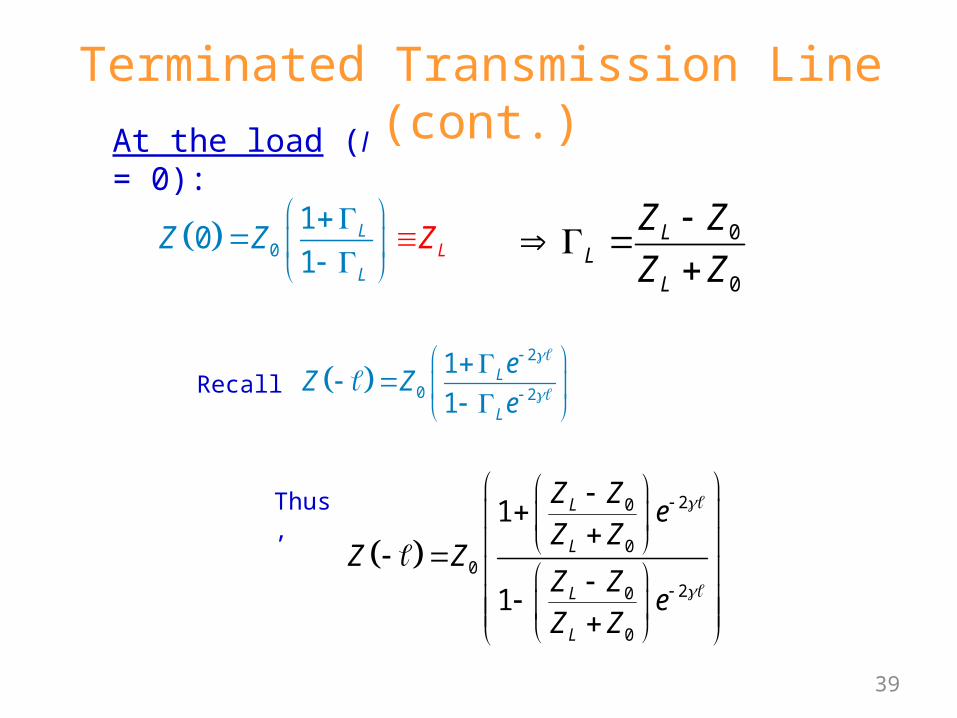
At the load (l = 0):
0
10
1L
LL
Z Z Z
Thus,
20
00
20
0
1
1
L
L
L
L
Z Ze
Z ZZ Z
Z Ze
Z Z
Terminated Transmission Line (cont.)
0
0
LL
L
Z Z
Z Z
2
0 2
1
1L
L
eZ Z
e
Recall
39

Simplifying, we have
00
0
tanh
tanhL
L
Z ZZ Z
Z Z
Terminated Transmission Line (cont.)
202
0 0 00 0 2
2 0 00
0
0 00
0 0
00
0
1
1
cosh sinh
cosh sinh
L
L L L
L LL
L
L L
L L
L
L
Z Ze
Z Z Z Z Z Z eZ Z Z
Z Z Z Z eZ Ze
Z Z
Z Z e Z Z eZ
Z Z e Z Z e
Z ZZ
Z Z
Hence, we have
40

20
20
0
2
0 2
1
1
1
1
j jL
j jL
jL
jL
V V e e
VI e e
Z
eZ Z
e
Impedance is periodic with period g/2
2
/ 2
g
g
Terminated Lossless Transmission Line
j j
Note: tanh tanh tanj j
tan repeats when
00
0
tan
tanL
L
Z jZZ Z
Z jZ
41

For the remainder of our transmission line discussion we will assume that the transmission line is lossless.
20
20
0
2
0 2
00
0
1
1
1
1
tan
tan
j jL
j jL
jL
jL
L
L
V V e e
VI e e
Z
V eZ Z
I e
Z jZZ
Z jZ
0
0
2
LL
L
g
p
Z Z
Z Z
v
Terminated Lossless Transmission Line
I(-l )
V(-l )+
l
ZL-
0 ,Z
Z
42

Matched load: (ZL=Z0)
0
0
0LL
L
Z Z
Z Z
For any l
No reflection from the load
A
Matched LoadI(-l )
V(-l )+
l
ZL-
0 ,Z
Z
0Z Z
0
0
0
j
j
V V e
VI e
Z
43

Short circuit load: (ZL = 0)
0
0
0
01
0
tan
L
Z
Z
Z jZ
Always imaginary!Note:
B
2g
scZ jX
S.C. can become an O.C. with a g/4 trans. line
0 1/4 1/2 3/4g/
XSC
inductive
capacitive
Short-Circuit Load
l
0 ,Z
0 tanscX Z
44

Using Transmission Lines to Synthesize Loads
A microwave filter constructed from microstrip.
This is very useful is microwave engineering.
45

00
0
tan
tanL
inL
Z jZ dZ Z d Z
Z jZ d
inTH
in TH
ZV d V
Z Z
I(-l)
V(-l)+
l
ZL
-0Z
ZTH
VTH
d
Zin
+
-
ZTH
VTH
+ZinV(-d)
+
-
Example
Find the voltage at any point on the line.
46

Note: 021 j
LjV V e e
0
0
LL
L
Z Z
Z Z
20 1j d j d in
THin TH
LV dZ
Ze V
ZV e
2
2
1
1
jj din L
TH j dm TH L
Z eV V e
Z Z e
At l = d :
Hence
Example (cont.)
0 2
1
1j din
TH j din TH L
ZV V e
Z Z e
47
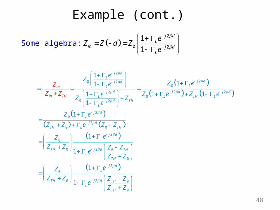
Some algebra: 2
0 2
1
1
j dL
in j dL
eZ Z d Z
e
2
20 20
2 220
0 2
20
20 0
2
0
20 0
0
111
1 11
1
1
1
1
j dL
j dj dLL
j d j dj dL TH LL
THj dL
j dL
j dTH L TH
j dL
j dTH THL
TH
in
in TH
eZ
Z ee
Z e Z eeZ Z
e
Z e
Z Z e Z Z
eZ
Z
Z
Z Z
Z Z Ze
Z Z
Z
2
0
20 0
0
1
1
j dL
j dTH THL
TH
e
Z Z Z Ze
Z Z
Example (cont.)
48
2
02
0
1
1
jj d L
TH j dTH S L
Z eV V e
Z Z e
20
20
1
1
j din L
j din TH TH S L
Z Z e
Z Z Z Z e
where 0
0
THS
TH
Z Z
Z Z
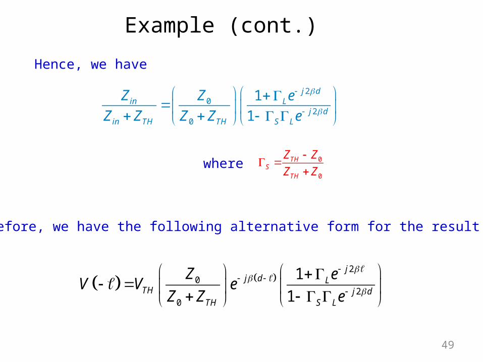
Example (cont.)
Therefore, we have the following alternative form for the result:
Hence, we have
49

2
02
0
1
1
jj d L
TH j dTH S L
Z eV V e
Z Z e
Example (cont.)
I(-l)
V(-l)+
l
ZL
-0Z
ZTH
VTH
d
Zin
+
-
Voltage wave that would exist if there were no reflections from the load (a semi-infinite transmission line or a matched load).
50

2 2
2 2 2 20
0
1 j d j dL L S
j d j d j d j dTH L S L L S L S
TH
e eZ
V d V e e e eZ Z
Example (cont.)
ZL0Z
ZTH
VTH
d
+
-
Wave-bounce method (illustrated for l = d ):
51

Example (cont.)
22 2
22 2 20
0
1
1
j d j dL S L S
j d j d j dTH L L S L S
TH
e e
ZV d V e e e
Z Z
Geometric series:
2
0
11 , 1
1n
n
z z z zz
2 2
2 2 2 20
0
1 j d j dL L S
j d j d j d j dTH L S L L S L S
TH
e eZ
V d V e e e eZ Z
2j dL Sz e
52

Example (cont.)
or
2
0
202
1
1
1
1
j dL s
THj dTH
L j dL s
eZV d V
Z Ze
e
2
02
0
1
1
j dL
TH j dTH L s
Z eV d V
Z Z e
This agrees with the previous result (setting l = d ).
Note: This is a very tedious method – not recommended.
Hence
53

00
0
tan
tanL T
in TT L
Z jZZ Z
Z jZ
2
4 4 2g g
g
00
Tin T
L
jZZ Z
jZ
0
20
0
0in in
T
L
Z Z
ZZ
Z
Quarter-Wave Transformer
20T
inL
ZZ
Z
so
1/2
0 0T LZ Z Z
Hence
This requires ZL to be real.
ZLZ0 Z0T
Zin
54

20 1 Lj j
LV V e e
20
20
1
1 L
j jL
jj jL
V V e e
V e e e
max 0
min 0
1
1
L
L
V V
V V
max
min
V
VVoltage Standing Wave Ratio VSWR
Voltage Standing Wave RatioI(-l )
V(-l )+
l
ZL-
0 ,Z
1
1L
L
VSWR
z
1+ L
1
1- L
0
( )V z
V
/ 2z 0z
55