
D4 2 Functional View on the BRIDGE Architecture final · Functional View on the BRIDGE Architecture...
136
Deliverable reference: Date: Responsible partner: D04.2 20 December 2013 FIT Bridging Resources and Agencies in Large-Scale Emergency Management BRIDGE is a collaborative project co‐funded by the European Commission within the Seventh Framework Programme (FP7‐SEC‐2010‐1) SEC‐2010.4.2‐1: Interoperability of data, systems, tools and equipment Grant Agreement No.: 261817 Duration: 1 April 2011 – 31 March 2015 www.sec‐bridge.eu Title: Functional View on the BRIDGE Architecture Editor(s): Approved by: Andreas Zimmermann Dag Ausen Classification: Public Abstract / Executive summary: The BRIDGE middleware supports the flexible assembly of emergency response systems into a ‘system of systems’ for agile emergency response. To the producers and users of emergency response systems, BRIDGE middleware offers a consolidated set of software services organized in three layers that facilitate the assembly and orchestration of systems, the communication between such systems, and the management of data produced by such systems during an incident’s life-cycle. The BRIDGE middleware forms the basis of all BRIDGE Concept Cases and underpins interoperability between different BRIDGE and external systems. This deliverable reports on the final software architecture of the BRIDGE middleware at the end of the second iteration. The methodology applied for the specification of the software architecture of the BRIDGE middleware is based on the standard IEEE 1471 ‘Recommended Practice for Architectural Description of Software-Intensive Systems’ which defines core elements like viewpoint and view. In order to implement and execute this methodology, we follow the approach introduced by Rozanski and Woods (2005). The deliverable represents the current state of software design and has been continuously updated and revised to incorporate the continuous improvements and integration of the BRIDGE middleware. It provides updates for all relevant parts of the software architecture description, and also, a testing of the software architecture based on the specification and implementation of the BRIDGE Concept Cases. These concept case perspectives on the BRIDGE middleware architecture help to explore the interplay and utilization of BRDIGE components to fulfil tasks related to emergency response. Document URL: http://www.sec-bridge.eu/deliverables/... ISBN number: 101010101010101
Transcript of D4 2 Functional View on the BRIDGE Architecture final · Functional View on the BRIDGE Architecture...

Deliverable reference: Date: Responsible partner:
D04.2 20 December 2013 FIT Bridging Resources and Agencies in Large-Scale Emergency Management
BRIDGE is a collaborative project co‐funded by the European Commission within the Seventh Framework Programme (FP7‐SEC‐2010‐1)
SEC‐2010.4.2‐1: Interoperability of data, systems, tools and equipment Grant Agreement No.: 261817
Duration: 1 April 2011 – 31 March 2015
www.sec‐bridge.eu
Title:
Functional View on the BRIDGE Architecture
Editor(s): Approved by: Andreas Zimmermann Dag Ausen
Classification:
Public Abstract / Executive summary:
The BRIDGE middleware supports the flexible assembly of emergency response systems into a ‘system of systems’ for agile emergency response. To the producers and users of emergency response systems, BRIDGE middleware offers a consolidated set of software services organized in three layers that facilitate the assembly and orchestration of systems, the communication between such systems, and the management of data produced by such systems during an incident’s life-cycle. The BRIDGE middleware forms the basis of all BRIDGE Concept Cases and underpins interoperability between different BRIDGE and external systems. This deliverable reports on the final software architecture of the BRIDGE middleware at the end of the second iteration. The methodology applied for the specification of the software architecture of the BRIDGE middleware is based on the standard IEEE 1471 ‘Recommended Practice for Architectural Description of Software-Intensive Systems’ which defines core elements like viewpoint and view. In order to implement and execute this methodology, we follow the approach introduced by Rozanski and Woods (2005). The deliverable represents the current state of software design and has been continuously updated and revised to incorporate the continuous improvements and integration of the BRIDGE middleware. It provides updates for all relevant parts of the software architecture description, and also, a testing of the software architecture based on the specification and implementation of the BRIDGE Concept Cases. These concept case perspectives on the BRIDGE middleware architecture help to explore the interplay and utilization of BRDIGE components to fulfil tasks related to emergency response.
Document URL: http://www.sec-bridge.eu/deliverables/...
ISBN number: 101010101010101
Version 1.0: Final 30.11.2013
D4.2: Functional View on the BRIDGE System Architecture Page 2 of 136
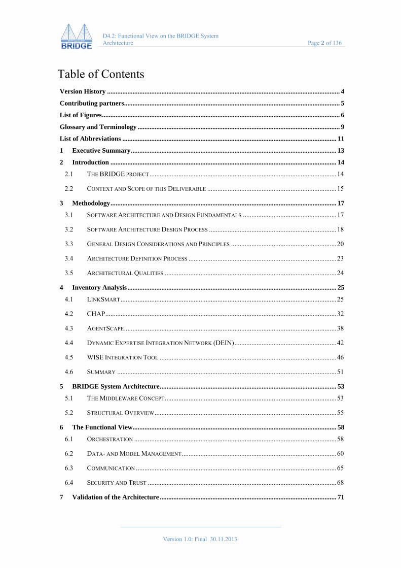
Table of Contents Version History ......................................................................................................................................... 4
Contributing partners ............................................................................................................................... 5
List of Figures ............................................................................................................................................ 6
Glossary and Terminology ....................................................................................................................... 9
List of Abbreviations .............................................................................................................................. 11
1 Executive Summary ......................................................................................................................... 13
2 Introduction ..................................................................................................................................... 14
2.1 THE BRIDGE PROJECT .............................................................................................................. 14
2.2 CONTEXT AND SCOPE OF THIS DELIVERABLE ............................................................................ 15
3 Methodology ..................................................................................................................................... 17
3.1 SOFTWARE ARCHITECTURE AND DESIGN FUNDAMENTALS ....................................................... 17
3.2 SOFTWARE ARCHITECTURE DESIGN PROCESS ........................................................................... 18
3.3 GENERAL DESIGN CONSIDERATIONS AND PRINCIPLES .............................................................. 20
3.4 ARCHITECTURE DEFINITION PROCESS ....................................................................................... 23
3.5 ARCHITECTURAL QUALITIES ..................................................................................................... 24
4 Inventory Analysis ........................................................................................................................... 25
4.1 LINKSMART ............................................................................................................................... 25
4.2 CHAP ........................................................................................................................................ 32
4.3 AGENTSCAPE ............................................................................................................................. 38
4.4 DYNAMIC EXPERTISE INTEGRATION NETWORK (DEIN) ............................................................ 42
4.5 WISE INTEGRATION TOOL ........................................................................................................ 46
4.6 SUMMARY ................................................................................................................................. 51
5 BRIDGE System Architecture ........................................................................................................ 53
5.1 THE MIDDLEWARE CONCEPT ..................................................................................................... 53
5.2 STRUCTURAL OVERVIEW ........................................................................................................... 55
6 The Functional View ........................................................................................................................ 58
6.1 ORCHESTRATION ....................................................................................................................... 58
6.2 DATA- AND MODEL MANAGEMENT ........................................................................................... 60
6.3 COMMUNICATION ...................................................................................................................... 65
6.4 SECURITY AND TRUST ............................................................................................................... 68
7 Validation of the Architecture ........................................................................................................ 71

Version 1.0: Final 30.11.2013
D4.2: Functional View on the BRIDGE System Architecture Page 3 of 136
7.1 ROBUST AND RESILIENT COMMUNICATION ............................................................................... 71
7.2 ADAPTIVE LOGISTICS ................................................................................................................ 80
7.3 FEDERATED CONTROL ROOM SUPPORT ..................................................................................... 85
7.4 ADVANCED SITUATION AWARENESS ......................................................................................... 88
7.5 DYNAMIC TAGGING OF THE ENVIRONMENT .............................................................................. 92
7.6 INFORMATION INTELLIGENCE .................................................................................................. 100
7.7 SITUATION-AWARE RESOURCE MANAGEMENT ....................................................................... 106
7.8 MASTER SYSTEM ..................................................................................................................... 108
7.9 FIRST RESPONDER INTEGRATED TRAINING SYSTEM ................................................................ 112
8 Architectural Qualities .................................................................................................................. 115
8.1 ARCHITECTURAL QUALITIES LIST ........................................................................................... 115
8.2 TOWARDS BRIDGE ELSI DESIGN GUIDELINES ...................................................................... 118
8.3 CONCLUSION ........................................................................................................................... 124
References .............................................................................................................................................. 125
Appendix A – Initial Services ............................................................................................................... 129

Version 1.0: Final 30.11.2013
D4.2: Functional View on the BRIDGE System Architecture Page 4 of 136
Version History
Version1 Description Date Who
1 Initial TOC.
Initial description of methodology.
18.10.2011 Jahn
2 Services/requirements list, draft component architecture model
22.11.2011 Ahlsen, Kool, Persson, Brodén
3 Description of Requirements Engineering
First Functional Descriptions
First internal version to be sent to WP leaders
12.12.2011 Ahlsen, Al-Akkad, Jahn, Zimmermann, Eide, Skjetne
4 Updated BRIDGE Architecture from Requirements Analysis
Draft of chapter ‘Functional View’ providing first description of services and related requirements
26.03.2012 Jahn, Matiouk Zimmermann, Ahlsen, Kool
5 Architecture update, Methodology revision, Inventory Analysis, Validation of the archiecture with concept case perspectives, Functional View update
24.05.2012 Jahn, Matiouk Zimmermann, concept case owners
6 Update of the Architecture Diagram Jun & Aug 2013
Zimmermann, Ahlsen, Kool
7 Contributing edits and chapter on architectural qualities and BRIDGE ELSI Design Guidelines
Sep & Nov 2013
Buscher, Liegl, Wahlgren
8 Submission for internal review & internal review
Dec 2013 Zimmermann, Wenstad, Wietek
9 Submission to the EC Dec 2013 Zimmermann
1 Note that the version number and description should correspond to the same information in the eRoom version control, thus version numbers are integers. See below for more information.

Version 1.0: Final 30.11.2013
D4.2: Functional View on the BRIDGE System Architecture Page 5 of 136
Contributing partners
Fraunhofer-Institut für Angewandte Informationstechnik FIT Schloss Birlinghoven 53754 Sankt Augustin, Germany
Andreas Zimmermann [email protected]
Svetlana Matiouk [email protected]
SINTEF Strindveien 4 7034 Trondheim Norway
Jan Skjetne, [email protected]
Aslak Wegner Eide, [email protected]
CNet Svenska AB
Svärdvägen 3B SE-182 33 Danderyd Sweden
Matts Ahlsen, [email protected]
Peeter Kool, [email protected]
ULANC
mobilities.lab Department of Sociology Lancaster University Lancaster, LA1 4YD, UK
Monika Buscher, [email protected]
Michael Liegl, [email protected]
USTOCK
Swedish Law and Informatics Research Institute, Faculty of Law Stockholm University 106 91 Stockholm, Sweden
Peter Wahlgren, [email protected]

Version 1.0: Final 30.11.2013
D4.2: Functional View on the BRIDGE System Architecture Page 6 of 136
List of Figures FIGURE 1 – ‘NEXT GENERATION ICT FOR THE RESILIENT SOCIETY’ (ADAPTED FROM MAEDA 2010)........... 14
FIGURE 2 – ARCHITECTURE DEFINITION ACTIVITIES (ROZANSKI, 2005) ..................................................... 18
FIGURE 3 – DETAILS OF THE ARCHITECTURE DEFINITION ACTIVITIES (ROZANSKI, 2005) .......................... 19
FIGURE 4 – VIEWPOINT CATALOGUE (ROZANSKI, 2005) ............................................................................. 20
FIGURE 5 – MIDDLEWARE DEVELOPMENT DRIVEN BY CONCEPT CASES ..................................................... 23
FIGURE 6 – LINKSMART OVERLAY NETWORK ............................................................................................ 26
FIGURE 7 – CLIENT-SERVER VS. PEER-TO-PEER .......................................................................................... 27
FIGURE 8 – SOAP TUNNELLING EXAMPLE.................................................................................................. 28
FIGURE 9 – SOAP TUNNEL ......................................................................................................................... 28
FIGURE 10 – TYPICAL WIRELESS SENSOR NETWORK CONFIGURATION ...................................................... 30
FIGURE 11 – CHAP VISION OF HYBRID HUMAN-COMPUTER PLATFORMS .................................................. 33
FIGURE 12 – CHAP CONCEPTUAL FRAMEWORK ......................................................................................... 34
FIGURE 13 – COMPARTMENTS OF CHAP LIBRARY FOR AGENT-BASED ALGORITHMS ................................ 34
FIGURE 14 – A FUNCTIONAL VIEW ON THE CHAP AGENT PLATFORM / MIDDLEWARE .............................. 36
FIGURE 15 – MAPPINGS BETWEEN CHAP AND AN ICT MIDDLEWARE ARCHITECTURE .............................. 37
FIGURE 16 – AGENTSCAPE PLATFORM ........................................................................................................ 38
FIGURE 17 – AGENTSCAPE LOOKUP SERVICE ............................................................................................. 39
FIGURE 18 – FUNCTIONAL VIEW ON THE AGENTSCAPE ARCHITECTURE ..................................................... 40
FIGURE 19 – INTERACTION BETWEEN AGENTS PROVIDING HETEROGENEOUS PROCESSING SERVICES .......... 44
FIGURE 20 – A GRAPHICAL USER INTERFACE SUPPORTS COMMUNICATION BETWEEN THE EXPERT AND HIS
(OR HER) DPIF AGENT ........................................................................................................................ 44
FIGURE 21 – A SIMPLIFIED EXAMPLE FROM CRISIS MANAGEMENT ............................................................. 45
FIGURE 22 – WISE CONNECTIVITY ............................................................................................................. 48
FIGURE 23 – LEARNING AND TRAINING METHODOLOGY ............................................................................ 49
FIGURE 24 – INFORMATION GATHERING AND HANDLING ........................................................................... 50
FIGURE 25 – USE OF EXISTING BASELINE TECHNOLOGY FOR THE BRIDGE MIDDLEWARE ........................ 51
FIGURE 26 – MIDDLEWARE LAYER ............................................................................................................. 54
FIGURE 27 – GENERIC MIDDLEWARE STACK .............................................................................................. 54
FIGURE 28 – STRUCTURAL OVERVIEW ON THE BRIDGE MIDDLEWARE SERVICES ..................................... 55
FIGURE 29 – VISUALISATION OF THE BRIDGE MESH TOPOLOGY ............................................................... 63

Version 1.0: Final 30.11.2013
D4.2: Functional View on the BRIDGE System Architecture Page 7 of 136
FIGURE 30 – INFRASTRUCTURE DIAGRAM OF THE BRIDGE MESH ............................................................. 73
FIGURE 31 – THE HELPBEACONS APP (LEFT) & FRONT OFFICER USING THE SEEKER DEVICE (RIGHT) ....... 73
FIGURE 32 – ROBUST & RESILIENT COMMUNICATION PERSPECTIVE .......................................................... 74
FIGURE 33 – MESH USE CASE DIAGRAM ..................................................................................................... 75
FIGURE 34 – MESH DEVICE ACTIVITY DIAGRAM ........................................................................................ 76
FIGURE 35 – MESH AND HELPBEACONS COMMUNICATION DIAGRAM ........................................................ 76
FIGURE 36 – HELPBEACONS AND SOS MOBILE APP USE CASE DIAGRAM .................................................. 77
FIGURE 37 – HELPBEACON ACTIVITY DIAGRAM ......................................................................................... 78
FIGURE 38 – SOS MOBILE APP ACTIVITY DIAGRAM .................................................................................. 79
FIGURE 39 – SIMPLE WORKFLOW ‘VICTIM EVACUATION’ .......................................................................... 81
FIGURE 40 – ADAPTIVE LOGISTICS PERSPECTIVE ........................................................................................ 82
FIGURE 41 – ADAPTIVE LOGISTICS USE CASE DIAGRAM ............................................................................ 83
FIGURE 42 – ADAPTIVE LOGISTICS ACTIVITY DIAGRAM ............................................................................. 84
FIGURE 43 – ADAPTIVE LOGISTICS COMMUNICATION DIAGRAM ................................................................ 85
FIGURE 44 – GEOGRAPHICAL VIEW OF BURN WOUND TEAM ...................................................................... 86
FIGURE 45 – PROCESS VIEW OF EVACUATION DECISION TEAM .................................................................. 87
FIGURE 46 – FEDERATED CONTROL ROOMS SUPPORT PERSPECTIVE ........................................................... 88
FIGURE 47 – UNMANNED AERIAL VEHICLE ................................................................................................ 89
FIGURE 48 – GROUND CONTROL STATION .................................................................................................. 89
FIGURE 49 – EXPERT SYSTEM ..................................................................................................................... 90
FIGURE 50 – PLUME DISPERSION MODEL .................................................................................................... 90
FIGURE 51 – ADVANCED SITUATION AWARENESS PERSPECTIVE ................................................................ 91
FIGURE 51 – ADVANCED SITUATION AWARENESS USE CASE DIAGRAM ..................................................... 92
FIGURE 52 – TAGGING THE ENVIRONMENT USING SYMBOLIC ICONS .......................................................... 93
FIGURE 53 – LOOKING ‘THROUGH’ THE TAGGING DEVICE USING AUGMENTED REALITY MODE ................ 94
FIGURE 54 – USING THE TAGGING DEVICE AS A MAP VIEWER SHOWING IMPORTANT TAGGED PLACES ..... 94
FIGURE 55 – SENSOR TAG ........................................................................................................................... 95
FIGURE 56 – A TRIAGE BRACELET .............................................................................................................. 95
FIGURE 57 – THE TRIAGE TABLET IN TWO MODES ..................................................................................... 96
FIGURE 58 – DYNAMIC TAGGING OF THE ENVIRONMENT PERSPECTIVE ...................................................... 97
FIGURE 59 – DYNAMIC TAGGING OF THE ENVIRONMENT AND ETRIAGE USE CASE DIAGRAM .................... 98
Version 1.0: Final 30.11.2013
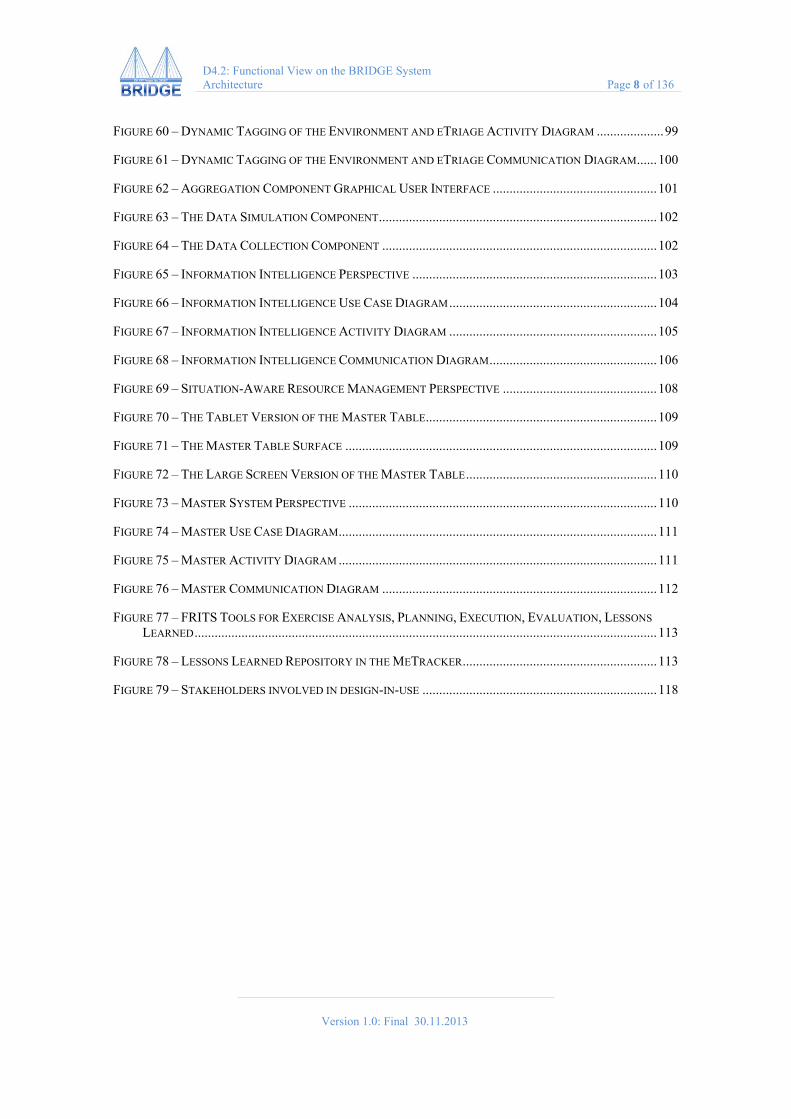
D4.2: Functional View on the BRIDGE System Architecture Page 8 of 136
FIGURE 60 – DYNAMIC TAGGING OF THE ENVIRONMENT AND ETRIAGE ACTIVITY DIAGRAM .................... 99
FIGURE 61 – DYNAMIC TAGGING OF THE ENVIRONMENT AND ETRIAGE COMMUNICATION DIAGRAM ...... 100
FIGURE 62 – AGGREGATION COMPONENT GRAPHICAL USER INTERFACE ................................................. 101
FIGURE 63 – THE DATA SIMULATION COMPONENT ................................................................................... 102
FIGURE 64 – THE DATA COLLECTION COMPONENT .................................................................................. 102
FIGURE 65 – INFORMATION INTELLIGENCE PERSPECTIVE ......................................................................... 103
FIGURE 66 – INFORMATION INTELLIGENCE USE CASE DIAGRAM .............................................................. 104
FIGURE 67 – INFORMATION INTELLIGENCE ACTIVITY DIAGRAM .............................................................. 105
FIGURE 68 – INFORMATION INTELLIGENCE COMMUNICATION DIAGRAM .................................................. 106
FIGURE 69 – SITUATION-AWARE RESOURCE MANAGEMENT PERSPECTIVE .............................................. 108
FIGURE 70 – THE TABLET VERSION OF THE MASTER TABLE ..................................................................... 109
FIGURE 71 – THE MASTER TABLE SURFACE ............................................................................................. 109
FIGURE 72 – THE LARGE SCREEN VERSION OF THE MASTER TABLE ......................................................... 110
FIGURE 73 – MASTER SYSTEM PERSPECTIVE ............................................................................................ 110
FIGURE 74 – MASTER USE CASE DIAGRAM ............................................................................................... 111
FIGURE 75 – MASTER ACTIVITY DIAGRAM ............................................................................................... 111
FIGURE 76 – MASTER COMMUNICATION DIAGRAM .................................................................................. 112
FIGURE 77 – FRITS TOOLS FOR EXERCISE ANALYSIS, PLANNING, EXECUTION, EVALUATION, LESSONS
LEARNED .......................................................................................................................................... 113
FIGURE 78 – LESSONS LEARNED REPOSITORY IN THE METRACKER .......................................................... 113
FIGURE 79 – STAKEHOLDERS INVOLVED IN DESIGN-IN-USE ...................................................................... 118
Version 1.0: Final 30.11.2013
D4.2: Functional View on the BRIDGE System Architecture Page 9 of 136
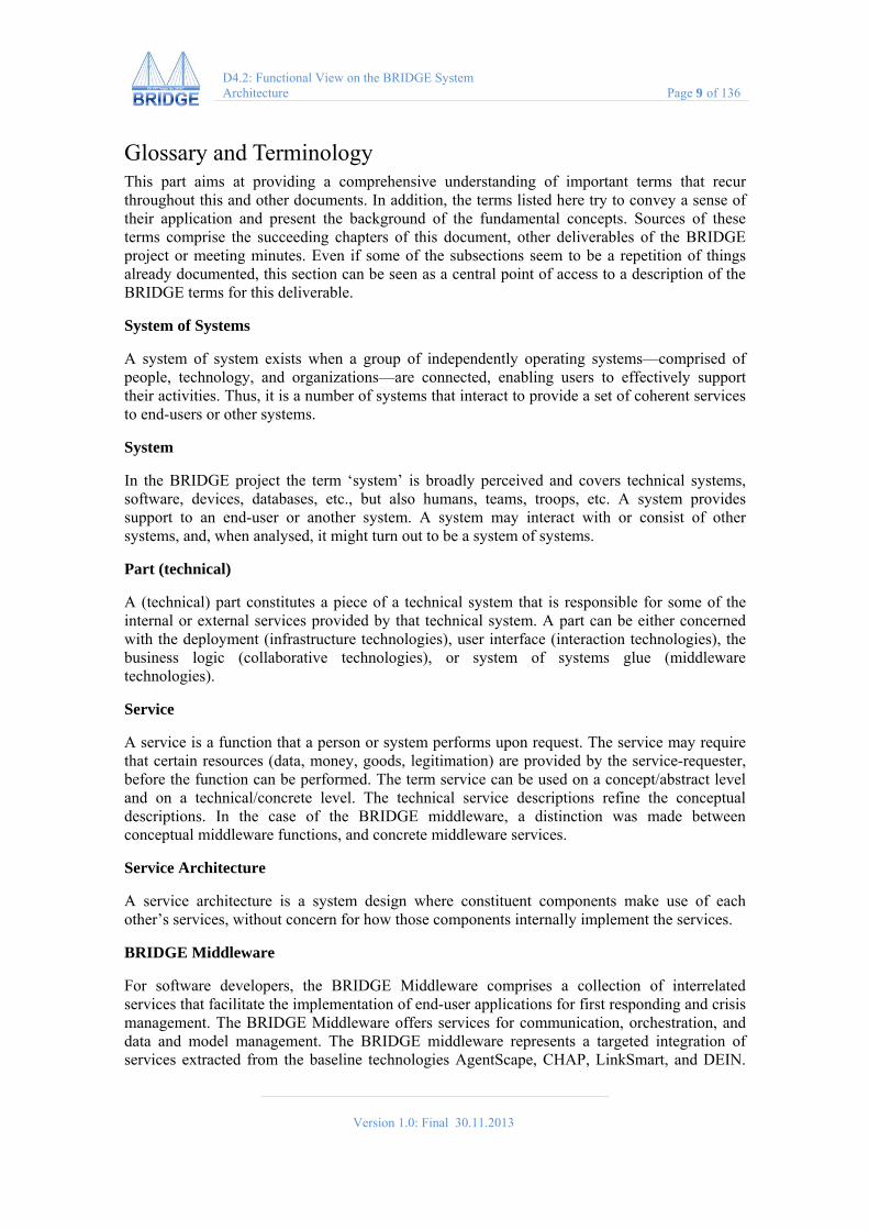
Glossary and Terminology This part aims at providing a comprehensive understanding of important terms that recur throughout this and other documents. In addition, the terms listed here try to convey a sense of their application and present the background of the fundamental concepts. Sources of these terms comprise the succeeding chapters of this document, other deliverables of the BRIDGE project or meeting minutes. Even if some of the subsections seem to be a repetition of things already documented, this section can be seen as a central point of access to a description of the BRIDGE terms for this deliverable.
System of Systems
A system of system exists when a group of independently operating systems—comprised of people, technology, and organizations—are connected, enabling users to effectively support their activities. Thus, it is a number of systems that interact to provide a set of coherent services to end-users or other systems.
System
In the BRIDGE project the term ‘system’ is broadly perceived and covers technical systems, software, devices, databases, etc., but also humans, teams, troops, etc. A system provides support to an end-user or another system. A system may interact with or consist of other systems, and, when analysed, it might turn out to be a system of systems.
Part (technical)
A (technical) part constitutes a piece of a technical system that is responsible for some of the internal or external services provided by that technical system. A part can be either concerned with the deployment (infrastructure technologies), user interface (interaction technologies), the business logic (collaborative technologies), or system of systems glue (middleware technologies).
Service
A service is a function that a person or system performs upon request. The service may require that certain resources (data, money, goods, legitimation) are provided by the service-requester, before the function can be performed. The term service can be used on a concept/abstract level and on a technical/concrete level. The technical service descriptions refine the conceptual descriptions. In the case of the BRIDGE middleware, a distinction was made between conceptual middleware functions, and concrete middleware services.
Service Architecture
A service architecture is a system design where constituent components make use of each other’s services, without concern for how those components internally implement the services.
BRIDGE Middleware
For software developers, the BRIDGE Middleware comprises a collection of interrelated services that facilitate the implementation of end-user applications for first responding and crisis management. The BRIDGE Middleware offers services for communication, orchestration, and data and model management. The BRIDGE middleware represents a targeted integration of services extracted from the baseline technologies AgentScape, CHAP, LinkSmart, and DEIN.
Version 1.0: Final 30.11.2013
D4.2: Functional View on the BRIDGE System Architecture Page 10 of 136
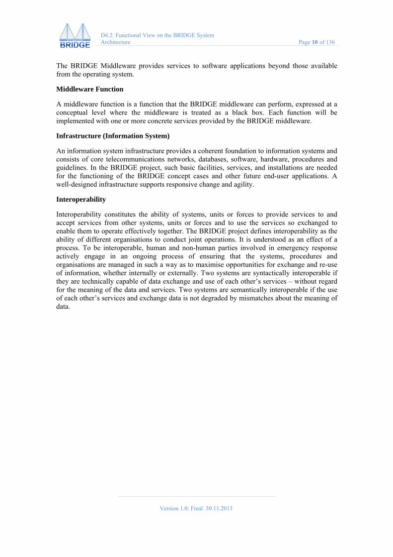
The BRIDGE Middleware provides services to software applications beyond those available from the operating system.
Middleware Function
A middleware function is a function that the BRIDGE middleware can perform, expressed at a conceptual level where the middleware is treated as a black box. Each function will be implemented with one or more concrete services provided by the BRIDGE middleware.
Infrastructure (Information System)
An information system infrastructure provides a coherent foundation to information systems and consists of core telecommunications networks, databases, software, hardware, procedures and guidelines. In the BRIDGE project, such basic facilities, services, and installations are needed for the functioning of the BRIDGE concept cases and other future end-user applications. A well-designed infrastructure supports responsive change and agility.
Interoperability
Interoperability constitutes the ability of systems, units or forces to provide services to and accept services from other systems, units or forces and to use the services so exchanged to enable them to operate effectively together. The BRIDGE project defines interoperability as the ability of different organisations to conduct joint operations. It is understood as an effect of a process. To be interoperable, human and non-human parties involved in emergency response actively engage in an ongoing process of ensuring that the systems, procedures and organisations are managed in such a way as to maximise opportunities for exchange and re-use of information, whether internally or externally. Two systems are syntactically interoperable if they are technically capable of data exchange and use of each other’s services – without regard for the meaning of the data and services. Two systems are semantically interoperable if the use of each other’s services and exchange data is not degraded by mismatches about the meaning of data.

Version 1.0: Final 30.11.2013
D4.2: Functional View on the BRIDGE System Architecture Page 11 of 136
List of Abbreviations 3G Third Generation (of mobile telecommunications technology)
6LoWPAN IPv6 over Low power Wireless Personal Area Network
AP Access Point
API Application Programming Interface
ASCII American Standard Code for Information Interchange
B.A.T.M.A.N Better Approach to Mobile Adhoc Networking
BP Bundle Protocol
BRI A requirement that has been elicited inside BRIDGE (e.g. BRI-128)
BSSID Basic Service Set Identifier
DOC Disasters Operations Center
DTN Delay/Disruption-tolerant Networking
EDXL Emergency Data Exchange Language
EMIS Emergency Management Information System
GPS Global Positioning System
GSM Global System for Mobile Communications
ICT Information and Communications Technology
IEEE Institute of Electrical and Electronics Engineers
IMEI International Mobile Equipment Identifier
IP Internet Protocol
LTE Long Term Evolution
MAC Medium Access Control
MD5 Message-Digest Algorithm 5
OLSR Optimized Link State Routing
OS Operating System
REST Representational State Transfer
RFC Request for Comments
S2D2S Secured Shared Distributed Data Space

Version 1.0: Final 30.11.2013
D4.2: Functional View on the BRIDGE System Architecture Page 12 of 136
SSID Service Set Identifier
TCP Transmission Control Protocol
TETRA Terrestrial Trunked Radio
UDP User Datagram Protocol
UMTS Universal Mobile Telecommunications System
UPnP Universal Plug and Play
Wi-Fi A wireless area network that is based on IEEE 802.11 standards
XML Extensible Markup Language
Version 1.0: Final 30.11.2013
D4.2: Functional View on the BRIDGE System Architecture Page 13 of 136
1 Executive Summary The BRIDGE middleware supports the flexible assembly of emergency response systems into a ‘system of systems’ for agile emergency response. Such ‘systems’ include BRIDGE concept cases, but also independent systems such as healthcare or vehicle registration records, building or environmental sensors, CCTV camera systems. To the producers of emergency response systems, BRIDGE middleware offers a consolidated set of software services organized in three layers that facilitate the orchestration of systems, the communication between such systems, and the management of data produced by such systems during an incident’s life-cycle. The BRIDGE middleware forms the basis of all BRIDGE Concept Cases and underpins interoperability between different BRIDGE- and external systems.
This deliverable reports on the final software architecture of the BRIDGE middleware. The methodology applied for the specification of the software architecture of the BRIDGE middleware is based on the standard IEEE 1471 ‘Recommended Practice for Architectural Description of Software-Intensive Systems’ which defines core elements like viewpoint and view. In order to implement and execute this methodology, we follow the approach introduced by Rozanski and Woods (2005).
The functional view documents the system’s structure, demonstrating how the system will perform required functions. Supportively, the information view (documented in deliverable D4.3) visualizes modelling of data in order to illustrate and further specify the composition of the middleware constituents and the communication among them. Also, the deployment view (also available with deliverable D4.3) defines the physical environment in which the system is intended to run, comprising different kinds of network nodes and devices, and the communication between them.
This deliverable represents the current state of software developments and has been continuously updated and revised to incorporate the continuous improvements and integration of the software of the BRIDGE middleware. It provides updates for all relevant parts of the software architecture description, and also, a test of the software architecture based on the specification and implementation of the BRIDGE Concept Cases. These concept case perspectives on the BRIDGE middleware architecture help to explore the interplay and utilization of BRDIGE components to fulfil tasks related to emergency response.

Version 1.0: Final 30.11.2013
D4.2: Functional View on the BRIDGE System Architecture Page 14 of 136
2 Introduction
2.1 The BRIDGE project The BRIDGE project develops computer infrastructures and systems that can help responders assemble ICT systems to support inter-organizational interoperability and information sharing. This research is inspired by calls for greater interoperability and coordination between emergency agencies (ENISA, 2012), best practice innovation that places an emphasis on data-sharing (Knight 2013) and opportunities for convergence between ‘smart city’ and crisis management systems, powerfully illustrated by Maeda et al’s vision of ‘Next Generation ICT Services for the Resilient Society’ (2010, Figure 1) in Japan:
Figure 1 – ‘Next generation ICT for the resilient society’ (adapted from Maeda 2010)
Such computer architectures can enable ‘one stop management’ of datasets ranging from personal activities (diaries, location, photographs, blogs) to employment, taxation and health records, telecommunications and risk registers. Researchers, organizations and governments in Brazil (Naphade et al, 2011), the Netherlands (Steenbruggen et al., 2013) and the UK (Johnson, 2012) are extending similar ‘one stop management’ to security and crisis management.
In the European context interconnections between legislative and executive agencies are governed by strict rules, but secure information sharing that respects these rules (or is exempt through exceptions) is seen as an important area for innovation. Coping with this challenge means addressing aspects such as trust, security, and privacy of information, which are not in the core research of the BRIDGE project as explicitly stated in the project description of work (see section 1.1.2 of BRIDGE’s DoW). However, to address such issues anyway, we will base our efforts in BRIDGE on the concepts and technology developed in the HYDRA project (funded by the European Commission). The LinkSmart middleware for networked embedded systems is available as open source, and it is deployable on both new and existing networks of distributed, heterogeneous devices, both wired and wireless. By exploiting LinkSmart’s technology for secure communication management, semantic context-based access control, trust policy and authorization, virtual identities, and authentication, the BRIDGE consortium can focus on its core objectives. Privacy-related aspects are tackled at full length in deliverable D12.1 – Privacy Protection and Legal Risk Analysis.
Version 1.0: Final 30.11.2013
D4.2: Functional View on the BRIDGE System Architecture Page 15 of 136
2.2 Context and Scope of this Deliverable The functional view of a software architecture defines the architectural elements that deliver the system’s functionality. This view documents the system’s functional structure that demonstrates how the system will perform the functions required of it. Functionality and quality are complementary properties of a system that is being designed. While functional requirements describe the functionality of the system being designed (what the system should do), the non-functional requirements describe the qualities of the system (how the system should operate).
This report details the services and components of the BRIDGE middleware as the core architectural elements. It provides an overview on what purpose and main functionalities each component serves, and documents what requirements they address. It also documents architectural qualities to ensure that broader requirements are not forgotten in the design process.
The functional view of the BRIDGE middleware architecture is based on the elicitation of a set of requirements, which have been identified in the process of domain analyses performed in work package 2 (WP2). Furthermore, the project partners introduced baseline technologies to the BRIDGE project that provided an advanced springboard for innovation. This needs to be tailored towards first responding, and therefore, it has an additional impact on the BRIDGE middleware and its specification. Representing end-user applications, the BRIDGE concept cases make intensive use of services offered by the BRIDGE middleware, which allows for a test of the BRIDGE middleware architecture. D4.2 documents the abovementioned aspects and is structured as follows:
Chapter 3 introduces the methodology applied in the BRIDGE architecture definition process. It describes the relationship between requirements and architecture and how we implement the IEEE 1471 standard (as proposed by Rozanski & Woods), defining the concepts of viewpoint and views. Furthermore, it introduces the concept of architectural qualities, which serve as non-functional requirements for the BRIDGE architecture.
Chapter 4 describes the baseline technologies brought into the BRIDGE project by individual project partners. This top-down inventory analysis results in an overview of what functionality provided by baseline technologies have been exploited to implement services of the BRIDGE middleware. We applied a mixed top-down and bottom-up approach to find the right balance between partners’ technologies brought into the project and BRIDGE requirements.
Chapter 5 provides a first structural overview of the BRIDGE architecture as it has been developed according to the requirements and taking into account the technical requirements of the different partners’ technologies provided by partners. It also introduces the middleware concept applied for the BRIDGE middleware.
Chapter 6 provides detailed descriptions of the functional view on the BRIDGE middleware architecture. It covers functional descriptions of all services/components and includes each service’s purpose, internal functionality, and addressed requirements.
Chapter 7 sums up the test of the BRIDGE middleware architecture by mapping the Concept Cases to the proposed architecture. Since each Concept Case makes use of services of the middleware, each concept case provides a certain perspective on the BRIDGE middleware architecture, providing hints to missing or needless services.
Chapter 8 puts architectural qualities in the loop of the design of the BRIDGE middleware architecture and ensures proper consideration of broader requirements in the design process. Architectural qualities represent non-functional requirements, and are therefore complementary to the functionality provided by the BRIDGE middleware. The chapter develops a first set of

Version 1.0: Final 30.11.2013
D4.2: Functional View on the BRIDGE System Architecture Page 16 of 136
guidelines for the design of information systems for IT Supported Crisis Management. These guidelines focus on ethical, legal and social issues large scale multi-agency emergency response, but the considerations involved connect with broader ELSI design challenges in IT Innovation. Hence, some more general design guidelines are also provided.

Version 1.0: Final 30.11.2013
D4.2: Functional View on the BRIDGE System Architecture Page 17 of 136
3 Methodology
3.1 Software Architecture and Design Fundamentals We have based our process on the standard IEEE 1471 ‘Recommended Practice for Architectural Description of Software-Intensive Systems’ which defines core elements like viewpoint and view. It also describes that stakeholders need to be involved and how to apply stakeholders needs to the architecture. This will be supported by the introduction of architectural qualities that describe the non-functional qualities of the software architecture.
3.1.1 Requirements and Architecture We have established a process to gather requirements in a structured way as is laid out in deliverable D2.1 – ‘Methodology, Infrastructure and Process for Requirements Engineering and Domain Analysis.’
First, vision scenarios have been generated within the scope of T2.1 ‘Empirically Grounded Scenario Thinking’. The creation of scenarios of end-user behaviour and interaction with BRIDGE system functionality is an extremely useful instrument for identifying key technological, security, socio-economic and business drivers for future end-user requirements. The scenarios documented in deliverable D2.1 provide a vision framework for the subsequent iterative requirements engineering phase.
The next step produces technically oriented scenarios from the project’s main vision focusing on the deployment and use of the BRIDGE system (documented in deliverable D2.2). Such technical context scenarios illustrate the benefits and functionality of a system for certain user groups with their typical tasks and goals (see Dzida & Freitag, 1998). These technical scenarios will be tentative, trying to capture the context of use for a certain user role and to illustrate how the BRIDGE system might support them.
The analysis of these domain data mainly gathered in WP2 leads to the formulation of initial requirements at different levels of detail and their aggregation in a structured way. The gathered data, which may be in descriptive format, is categorized, classified, and finally transformed to system requirements that display an immediate technical effect on the future BRIDGE system.
Resulting functional and non-functional requirements are formalized according to the Volere scheme and tracked in a requirements database. This formalized process allows keeping track of the requirements in the iterative system development process and to quickly adapt to changing or upcoming requirements.
Requirements and architecture influence one another. Requirements are an input for the architectural design process in that they frame the architectural problem and explicitly represent the stakeholders’ needs and desires. On the other hand during the architecture design to the BRIDGE partners will take into consideration what is possible and look at the requirements from a risk/cost perspective.
3.1.2 Viewpoints & Views The IEEE 1471 standard defines viewpoint and view as follows:
Definition: Viewpoint and View
A viewpoint is a collection of patterns, templates and conventions for constructing one type of view. It defines the stakeholders whose concerns are reflected in the viewpoint, and guidelines and principles and template models for constructing its views.

Version 1.0: Final 30.11.2013
D4.2: Functional View on the BRIDGE System Architecture Page 18 of 136
A view is a representation of all or part of an architecture, from the perspective of one or more concerns which are held by one or more of its stakeholders.
A viewpoint defines the aims, intended audience, and content of a class of views and defines the concerns that views of this class will address e.g. Functional viewpoint or Deployment Viewpoint.
A view conforms to a viewpoint and so communicates the resolution of a number of concerns (and a resolution of a concern may be communicated in a number of views).
3.2 Software Architecture Design Process Rozanski and Woods have based the architectural design process on the following definition:
Definition: Architectural Design Process
Architecture Definition is a process by which stakeholder needs and concerns are captured, an architecture to meet these needs is designed, and the architecture is clearly and unambiguously described via an architectural description. (Rozanski, 2005)
We have to consider a broad set of principles if the architectural design should be of good quality. We need to engage stakeholders to collect their concerns so the requirements can be balanced if there are conflicting or incompatible ones. The architectural design must allow for effective communication between all stakeholders and it must be structured to ensure continuous progress. Given the complexity of the project the design and also the process have to be flexible so we can react quickly to changing requirements and environments.
3.2.1 Architecture Definition Activities The foundation for our process is the IEEE 1471 standard and we have used the process proposed by Rozanski and Woods, which is aligned to this standard:
Figure 2 – Architecture Definition Activities (Rozanski, 2005)
The process implemented in the BRIDGE project clearly reflects this approach. We started with the initial scope and context and the involvement of stakeholders in the process of the scenario development in WP2 and the subsequent requirements process. The stakeholders were included

Version 1.0: Final 30.11.2013
D4.2: Functional View on the BRIDGE System Architecture Page 19 of 136
to express their needs and desires and capture quality properties. Those requirements from the discussion rounds together with requirements from other sources are the input for the current architecture design phase where we create a first draft of the architectural description.
Based on this architectural description, the first prototype has been created, which can be seen as a skeleton system with minimal functionality on top. The experiences gained from these development efforts constitute a valuable source for the derivation of additional requirements and the revision of already existing ones. The following diagram reflects the details of the process:
Figure 3 – Details of the Architecture Definition Activities (Rozanski, 2005)
Steps 1 and 2 are reflected in the requirements process and steps 3 and 4 were basically defined by the DOW. In the DOW we have decided to implement a middleware based on a service-oriented architecture (SOA) through the use Web Services. With this as a framework the candidate architecture was set so we would only chose another architectural style if we would face insurmountable problems which are very unlikely.
The steps 5 to 7 (A and B) reflect our iterative approach on constantly refining the architecture and checking back with the stakeholders if the architecture meets their needs. After this iteration cycle the next steps of implementation and testing the revised architecture will follow but are not scope of this document.
3.2.2 Viewpoint Catalogue The viewpoint catalogue proposed by Rozanski and Woods contains the following viewpoints:

Version 1.0: Final 30.11.2013
D4.2: Functional View on the BRIDGE System Architecture Page 20 of 136
Functional: The system´s functional elements, their responsibilities and primary interactions with other elements will be described. This is usually the most important viewpoint as it reflects the quality properties of the system and influences the maintainability, the extensibility and the performance of the system.
Information: Describes the way that information is stored, managed and distributed in the architecture.
Concurrency: Describes the concurrency structure of the system and identifies components that can be executed concurrently and how this is coordinated and controlled.
Development: Describes how the architecture supports the development process.
Deployment: Describes the environment that the system will be deployed into and also documents the hardware requirements for the components and the mapping of the components to the runtime environment that will execute them.
Operational: Describes how the system will be operated, administered and supported while it is running and strategies and conflict resolutions will be documented here.
The following diagram shows how the viewpoints relate to each other.
Figure 4 – Viewpoint Catalogue (Rozanski, 2005)
During the course of the project this document will be continuously and successively extended by additional views.
3.3 General Design Considerations and Principles BRIDGE systems are spread over a large number of systems, devices and services that again can spread over large spatial areas. For those highly distributed systems, some basic design principles have to be considered. This section enumerates and describes an array of general design considerations that form the character and affect the BRIDGE architecture. These issues influence implicitly but also explicitly the software development process of the BRIDGE middleware.
3.3.1 Distributed vs. Centralized Approach Future BRIDGE systems combine several hard- and software components such as content, applications, displays, etc. required for the delivery of multi-purpose services. Users of such

Version 1.0: Final 30.11.2013
D4.2: Functional View on the BRIDGE System Architecture Page 21 of 136
BRIDGE systems will share their content with other users either over a network or through other storage media. The BRIDGE project aims at establishing interoperability between several systems and devices of a single user, but also among users. In addition, BRIDGE focuses on applications and services that will be deployed in environments, in which parts of the application need to be distributed. The distribution occurs on two different levels: on a conceptual level where information is distributed and on an implementation level where system components are distributed. A management of distributed components occurs in a centralized or decentralized manner.
A centralized approach is based upon a centralized component or server for several types of information and services, which provide requested information to the applications running on several systems and devices. This approach decouples the acquisition of information (content, user-related information, context, system properties, etc.) from the processing of this information. These applications can actively request the desired information from the server or passively be notified about changes. The server collects all information from accordant acquisition components and provides it to interested applications. A centralized approach suffers from restricted scalability, in consequence of a maximum of applications that can be served by the server. In addition, the problem of privacy rises, since all user-related information is bundled and stored in one place.
Instead of maintaining all information and services in one centralized place, a de-centralized approach holds the information at several places to avoid a potential bottleneck. Small devices or nodes in a network maintain the information required by the application themselves and process it directly. This approach requires the device to have the capability to store and process all of the necessary data, which may not be efficiently achieved for a simple system or device with restrictions concerning space, weight, or energy consumption. The decentralized approach avoids the lacking scalability of the centralized approach and allows the user to control how their personal information is published and thus, their privacy is guaranteed.
3.3.2 Coupling and Cohesion Between the components of a software architecture, two important types of relations can be identified, the inter-component coupling and the intra-component cohesion:
inter-component coupling refers to the width and complexity of the interfaces between the components,
intra-component cohesion refers to the affinity or relatedness between the constituents of one component
The components of a software architecture need to be designed in a way that minimizes inter-component coupling, and maximize intra-component cohesion. The ‘ideal’ component does not adhere to another component and does not collapse. This design principle is called ‘Structured Design’ and has been published by Stevens, Myers, Constantine (1974).
A high coupling between the components causes an extensive and uncertain maintenance of the system, since corrections and changes are distributed upon several units. A low coherence between the constituents of one component demands the splitting up of this component, since the resulting fragments offer a facilitated understanding and a better maintainability. Therefore, both a low coupling and a high cohesion result in a high locality and for this reason a good maintainability. The services BRIDGE middleware should be loosely-coupled among them and show a strong cohesion among their internal constituents.

Version 1.0: Final 30.11.2013
D4.2: Functional View on the BRIDGE System Architecture Page 22 of 136
3.3.3 Separation of Concerns The design principle ‘Separation of Concerns’ constitutes a fundamental principle of software engineering. For the design of the software architecture it is essential that each component is only responsible for one very specific scope of functions. Components that cover multiple functions and tasks at the same time are needlessly complex. In turn, this complexity complicates the understanding, and therefore, the maintainability and the further development also. In addition, the reuse of such components becomes limited.
3.3.4 Providing Redundancy In distributed systems – independent of their degree of decentralization – a certain redundancy of contents and services must be assured to safeguard robustness.
The BRIDGE middleware must guarantee robustness, independent of its degree of centralization. In centralized systems, the client-server architecture may depend too much on the reliability of the central components and the devices onto which they are deployed. Here, the servers might not only be performance bottlenecks but also a weak point in terms of robustness. A faulty server can cause a failure of the whole system.
If information is distributed over multiple systems and devices, the failure of a single information serving system is not as crucial to the functionality of the whole system as in a centralized system. Instead, the problem of finding and accessing information is relevant for the robustness in a decentralized system: Client devices must know the device, which holds specific information. Without a central server, this knowledge must be distributed over all devices as well as the information itself. Redundancy of content and services increases the probability, that clients find information in a distributed system.
An appropriate structuring of the BRIDGE system of systems through system architecture is essential. As a partitioning scheme for software, such architecture separates concerns and directs the distribution of the architecture constituents. This aspect is covered in deliverable D4.3 – Information and Deployment View on the BRIDGE System Architecture.
3.3.5 Simplicity vs. Complexity The paradigm of End-User Development (Fischer, 2002; Liebermann et al., 2006) aims at empowering end-users to configure and compose the information technology according to their diverse and changing needs. At the core of End-User Development research is the question how to reduce the complexity the user is confronted with when adapting and configuring technology. Therefore, Mørch (1997) introduced three levels of complexity that avoid big jumps in complexity and address users at different stages of expertise and development skill. These levels allow users to
select between predefined behaviours, compose a desired application out of existing modules, and fully access the code base of an application.
This property of avoiding big jumps in complexity to attain a reasonable trade-off is called the ‘gentle slope of complexity’ (MacLean et al., 1990; Dertouzos, 1997; Wulf and Golombek, 2001; Beringer, 2004). Users have to be able to make small changes in a simple way, while more complicated ones should only involve a proportional increase in the complexity the user is confronted with. The software architecture of the BRIDGE middleware needs to achieve this gentle slope of complexity through the increase of the flexibility of the underlying technology. Object-oriented and component-based software paradigms allow for the introduction of different

Version 1.0: Final 30.11.2013
D4.2: Functional View on the BRIDGE System Architecture Page 23 of 136
levels of complexity that address several expertise levels of a variety of users according to their specific roles.
3.4 Architecture Definition Process The architecture definition started early in the lifecycle of the BRIDGE project. Project scope and requirements were still blurry, since the design space for BRIDGE innovation was not fully understood in the beginning. When the BRIDGE project started, the size and extent of the BRIDGE middleware were not completely known, where the complexity is, what the most significant risk are, or where conflicts among stakeholders will encounter.
For this reason, the architecture definition process tends to be a more fluid activity than later tasks such as designing, building, and testing, and several iterations are necessary until the final architecture specification is reached. The initial view of the system may differ substantially from what is eventually built. Besides the iterative architecture definition, the specification of the BRIDGE middleware was driven and approached in both a top-down and a bottom-up manner (see Figure 5).
Figure 5 – Middleware Development driven by Concept Cases
As the top-down approach, an inventory analysis has been conducted based on the technologies, platforms and middleware that the individual partners brought into the BRIDGE project (see Chapter 4). These baseline technologies are:
LinkSmart CHAP AgentScape DEIN WISE
These baseline technologies form the basis for the middleware development in the BRIDGE project, since the goal is to integrate partner’s technologies to produce a middleware core tailored to first responding. Therefore, this top-down approach revealed software components
Version 1.0: Final 30.11.2013
D4.2: Functional View on the BRIDGE System Architecture Page 24 of 136
and services that could be extracted from their original source and integrated with the BRIDGE middleware.
As the bottom-up approach, several architecture definition workshops and requirements engineering activities have been conducted. Functional and non-functional requirements have been reviewed and taken into consideration during the architecture definition process. In the functional descriptions in Chapter 6 each service is linked to the relevant requirements allowing a validation of each service against the related requirements. Based on this requirements analysis, an initial set of required services (see Appendix A) has been defined during the architecture workshops.
A verification of the BRIDGE middleware architecture in terms of coverage of services has been achieved by applying the concept cases. Each concept case represents an end-user application whose implementation is based on individual parts and services of the BRIDGE middleware, and therefore, each concept case represents an ‘instantiation’ of the BRIDGE middleware architecture and provides a specific perspective on the services offered by the BRIDGE middleware. For this reason, the set of concept cases as a whole allows an assessment of the coverage of the BRIDGE middleware service with regard to end-user applications, and therefore a verification of the respective architecture (see Chapter 7).
3.5 Architectural Qualities Functionality and quality are complementary properties of a system that is being designed. While Functional Requirements describe the functionality of the system being designed (what the system should do), the Non-Functional Requirements describe the qualities of the system (how the system should operate).
Architectural qualities (see Chapter 8) ensure that broader requirements are not forgotten in the design process because the viewpoint and view approach per se does not explicitly consider non-functional requirements. But attention to such requirements is critical to the success of innovation and to reflect them properly one usually needs cross-view considerations.
For identification of relevant qualities standard ISOs have been considered:
ISO 22320: Societal security. Emergency management. Requirements for command and control
ISO 9126::Information technology – Software product quality – Part 1: Quality model, 2001
Further, within the process of domain analysis a set of requirements related to ethical, legal and social issues have been identified, and included in the list of architectural qualities. The architectural qualities listed in Chapter 8 represent the current state of analysis of the emergency management domain and need to be understood as guidelines that support IT developers in their realisation of emergency management information systems. Architectural qualities also represent non-functional requirements for emergency management information systems and their respective architectures.

Version 1.0: Final 30.11.2013
D4.2: Functional View on the BRIDGE System Architecture Page 25 of 136
4 Inventory Analysis In this chapter we present the results of the inventory analysis. The goal of this analysis was to identify the different technologies that partners bring into the project and to find out if and how the BRIDGE system could benefit from these technologies. Therefore, for each technology, we identified possible connection factors to the BRIDGE architecture.
In the following we provide for each technology a brief introduction and an analysis of their applicability in BRIDGE.
4.1 LinkSmart LinkSmart will mainly be used to setup the BRIDGE network, integrate different devices by Proxies, provide discovery of these devices and managing them in a registry.
On the level of Central BRIDGE Middleware Services, LinkSmart already provides a working Event Manager for Web Services.
From the security perspective, LinkSmart already implements Trust Management and a Cryptography module for encrypting and decrypting messages.
Of course not all marked components can be used out of the box for BRIDGE. Some might need to be extended and adapted to meet the specific BRIDGE requirements, while some might be applied in BRIDGE with relative ease. In the following we provide descriptions of each service, how it is implemented in LinkSmart and what needs to be considered when using it in BRIDGE.
4.1.1 Peer-to-Peer Networking The LinkSmart P2P network is based on the P2P network from the baseline Hydra project and uses the same model. The Network Manager is the component responsible of creating and maintaining the P2P network. The main objective of the Network Manager is to interconnect different devices and services through the network. The main problem of this task is that most of the devices and services may be hidden in Local Area Networks, behind firewalls, routers and Network Addressing Translators (NATs), so it would be difficult to interconnect directly.
However, the Network Manager solves this problem by building an overlay network, independently of the network addressing and protocols. The Network Manager relies on JXTA P2P platform in order to build the overlay network. JXTA is a set of open, generalised P2P protocols enabling any connected device on the network to communicate and collaborate. Using the JXTA protocols, devices and services are directly connected even if they are connected in different networks separated by firewalls or NATs.
Figure 6 shows an example of how the different devices and services are interconnected in the LinkSmart overlay network and how the actual network could look like. In order to make services and devices available on the P2P network they need to register their services (i.e. endpoints) with the network manager. The network creates a unique ID for the service, called HID, which is then used for addressing the service.

Version 1.0: Final 30.11.2013
D4.2: Functional View on the BRIDGE System Architecture Page 26 of 136
Figure 6 – LinkSmart Overlay Network
The HIDs are shared and synchronized among the network managers in the network. In effect all network managers know which HIDs are available in the network. This table of HIDs is referred to as the ID table, see the following table:
HID Endpoint Description Peer ID
223.122.33.33 http://127.0.0.1:8093/svc Thermometer 1
223.888.1.33 Thermometer 2
223.877.33.22 OntologyManager 2
The ID table contains the following data:
HID: That address that is used for the service
Endpoint: The actual endpoint of the service (in fact this field is not synchronised in-between network managers, for security and performance reasons). So the endpoint is only known to the Network Manager were the service registered. In the example above only the services belonging to Peer ID=1 are known
Description: an optional field where a simple description of the service can be stored.
Peer ID: The ID of the network manager that manages the service.
Version 1.0: Final 30.11.2013
D4.2: Functional View on the BRIDGE System Architecture Page 27 of 136
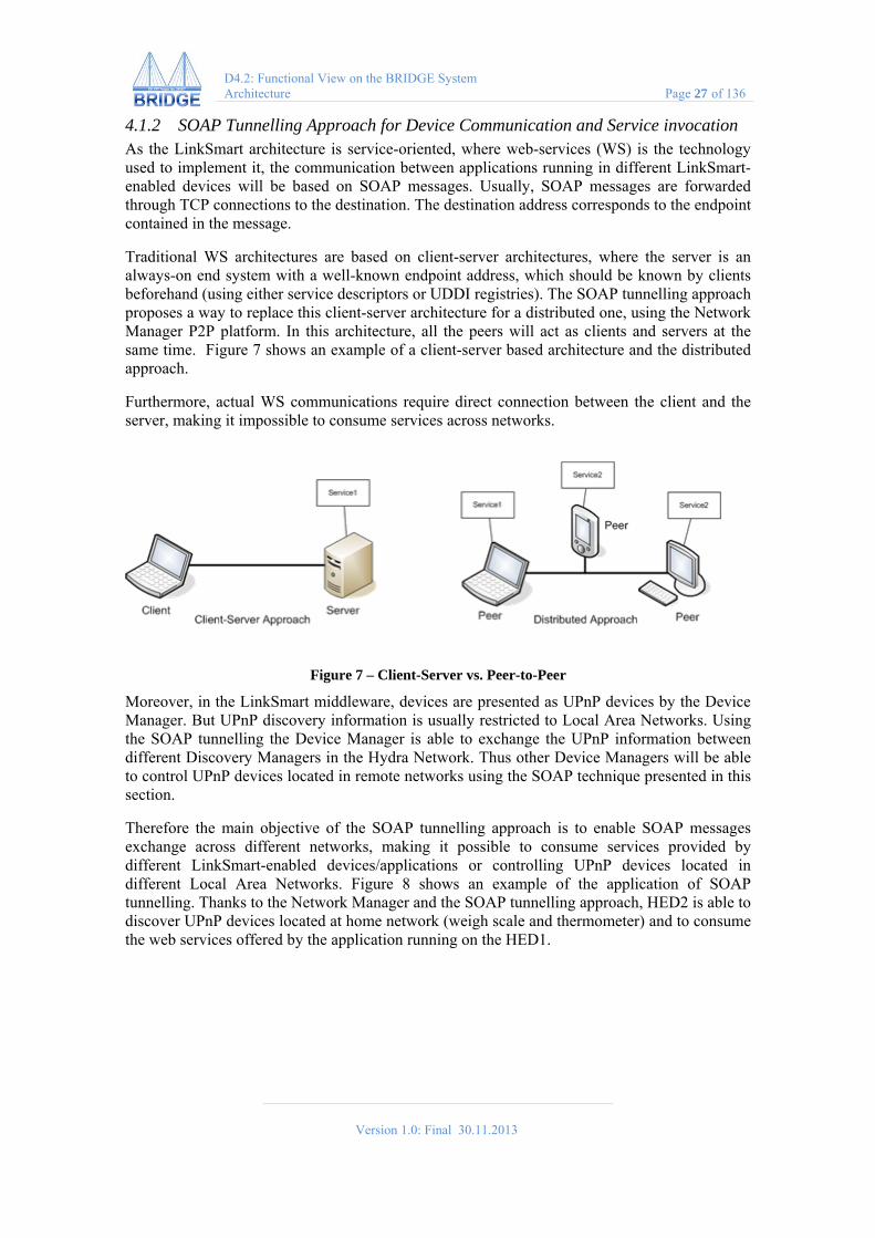
4.1.2 SOAP Tunnelling Approach for Device Communication and Service invocation As the LinkSmart architecture is service-oriented, where web-services (WS) is the technology used to implement it, the communication between applications running in different LinkSmart-enabled devices will be based on SOAP messages. Usually, SOAP messages are forwarded through TCP connections to the destination. The destination address corresponds to the endpoint contained in the message.
Traditional WS architectures are based on client-server architectures, where the server is an always-on end system with a well-known endpoint address, which should be known by clients beforehand (using either service descriptors or UDDI registries). The SOAP tunnelling approach proposes a way to replace this client-server architecture for a distributed one, using the Network Manager P2P platform. In this architecture, all the peers will act as clients and servers at the same time. Figure 7 shows an example of a client-server based architecture and the distributed approach.
Furthermore, actual WS communications require direct connection between the client and the server, making it impossible to consume services across networks.
Figure 7 – Client-Server vs. Peer-to-Peer
Moreover, in the LinkSmart middleware, devices are presented as UPnP devices by the Device Manager. But UPnP discovery information is usually restricted to Local Area Networks. Using the SOAP tunnelling the Device Manager is able to exchange the UPnP information between different Discovery Managers in the Hydra Network. Thus other Device Managers will be able to control UPnP devices located in remote networks using the SOAP technique presented in this section.
Therefore the main objective of the SOAP tunnelling approach is to enable SOAP messages exchange across different networks, making it possible to consume services provided by different LinkSmart-enabled devices/applications or controlling UPnP devices located in different Local Area Networks. Figure 8 shows an example of the application of SOAP tunnelling. Thanks to the Network Manager and the SOAP tunnelling approach, HED2 is able to discover UPnP devices located at home network (weigh scale and thermometer) and to consume the web services offered by the application running on the HED1.

Version 1.0: Final 30.11.2013
D4.2: Functional View on the BRIDGE System Architecture Page 28 of 136
Figure 8 – SOAP Tunnelling Example
4.1.3 SOAP Tunnelling The LinkSmart Network Manager enables a way to communicate with different devices transparently, building an overlay network in which resources (devices, services and contents) can be addressed. The main objective of the SOAP tunnelling communication used is to provide SOAP messages exchange using the P2P transport schemes provided by the Network Manager. In order to use P2P networking/addressing/transport schemes together with web services and UPnP we need some kind of virtualization of endpoints that allow us to use P2P networking. For this reason, all endpoints for UPnP and web service calls are grounded in a SOAP sink (ideally locally) which repackages the SOAP message and routes it through the Network Manager, as shown in Figure 9. The Network Manager is responsible of the message transmission and finally calls the SOAP sink that performs a local SOAP call to the intended SOAP endpoint.
Figure 9 – SOAP Tunnel
Version 1.0: Final 30.11.2013
D4.2: Functional View on the BRIDGE System Architecture Page 29 of 136
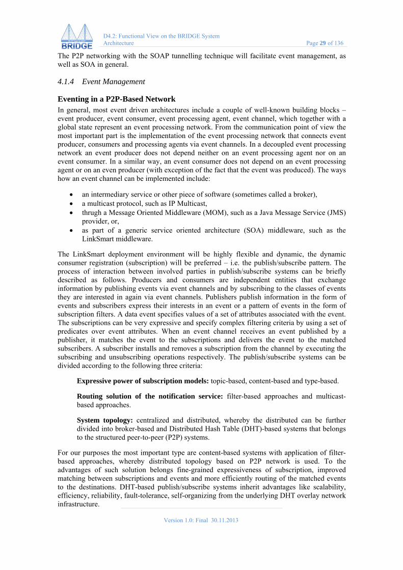
The P2P networking with the SOAP tunnelling technique will facilitate event management, as well as SOA in general.
4.1.4 Event Management
Eventing in a P2P-Based Network In general, most event driven architectures include a couple of well-known building blocks – event producer, event consumer, event processing agent, event channel, which together with a global state represent an event processing network. From the communication point of view the most important part is the implementation of the event processing network that connects event producer, consumers and processing agents via event channels. In a decoupled event processing network an event producer does not depend neither on an event processing agent nor on an event consumer. In a similar way, an event consumer does not depend on an event processing agent or on an even producer (with exception of the fact that the event was produced). The ways how an event channel can be implemented include:
an intermediary service or other piece of software (sometimes called a broker), a multicast protocol, such as IP Multicast, thrugh a Message Oriented Middleware (MOM), such as a Java Message Service (JMS)
provider, or, as part of a generic service oriented architecture (SOA) middleware, such as the
LinkSmart middleware.
The LinkSmart deployment environment will be highly flexible and dynamic, the dynamic consumer registration (subscription) will be preferred – i.e. the publish/subscribe pattern. The process of interaction between involved parties in publish/subscribe systems can be briefly described as follows. Producers and consumers are independent entities that exchange information by publishing events via event channels and by subscribing to the classes of events they are interested in again via event channels. Publishers publish information in the form of events and subscribers express their interests in an event or a pattern of events in the form of subscription filters. A data event specifies values of a set of attributes associated with the event. The subscriptions can be very expressive and specify complex filtering criteria by using a set of predicates over event attributes. When an event channel receives an event published by a publisher, it matches the event to the subscriptions and delivers the event to the matched subscribers. A subscriber installs and removes a subscription from the channel by executing the subscribing and unsubscribing operations respectively. The publish/subscribe systems can be divided according to the following three criteria:
Expressive power of subscription models: topic-based, content-based and type-based.
Routing solution of the notification service: filter-based approaches and multicast-based approaches.
System topology: centralized and distributed, whereby the distributed can be further divided into broker-based and Distributed Hash Table (DHT)-based systems that belongs to the structured peer-to-peer (P2P) systems.
For our purposes the most important type are content-based systems with application of filter-based approaches, whereby distributed topology based on P2P network is used. To the advantages of such solution belongs fine-grained expressiveness of subscription, improved matching between subscriptions and events and more efficiently routing of the matched events to the destinations. DHT-based publish/subscribe systems inherit advantages like scalability, efficiency, reliability, fault-tolerance, self-organizing from the underlying DHT overlay network infrastructure.
Version 1.0: Final 30.11.2013
D4.2: Functional View on the BRIDGE System Architecture Page 30 of 136
Peer-to-Peer Eventing in LinkSmart The initial LinkSmart event mechanism is based on a topic/content-based, publish-and-subscribe architecture. The LinkSmart Event Manager is deployed as a service in close cooperation with other components, among them the Network Manager, providing publish/subscribe functionality, i.e., the ability for publishers to send a notification to multiple subscribers while being decoupled from them (as described in the previous paragraph).
The architecture of LinkSmart has been characterized as event-driven SOA, integrating intelligent services with advanced semantic event processing and business rules, and the platform thus relies on the secure delivery of events. The basic event manager is being extended in several ways in order to support reliable eventing. Among the extension are,
Delay tolerance. In the event of communication failures, the system must still prevent loss of events. Store and forward functionality should be provided to guarantee delivery. This will make use of the opportunistic networking features such as the delay tolerance.
Storage. Delay tolerance by means of store and forward implies that the event manager must have storage available. Local caching will be combined with event databases accessible by all networked nodes that process events. An event database will also be used by the functions above the network layer, such as the business rule engine for evaluating rules which may depend on previous events.
Time Synchronisation. Time is of essence when processing events, there is a need to synchronise time in the distributed LinkSmart system architecture because the business rules can express time dependence in the rules. Even though delay tolerance will guarantee delivery of events, it does not guarantee the order of arrival. There is a need to time stamp events in order to be able to order the events in the correct time sequence. Since the network might bridge firewalls etc. it might not possible to use a NTP server for this. Therefore the Network Manager part of the event management architecture should be extended with functionality to synchronise time in-between the different nodes in the LinkSmart network.
Stateful Event Processing and Persistency. The processing of an event may be dependent upon one or several other events. It must be possible to maintain an event history (log) and to have access to any results or side-effects of the events occurred. The latter is supported by provision of persistent storage on the event processing nodes in the architecture.
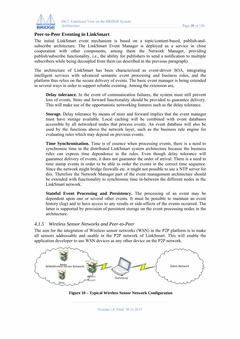
4.1.5 Wireless Sensor Networks and Peer-to-Peer The aim for the integration of Wireless sensor networks (WSN) in the P2P platform is to make all sensors addressable and usable in the P2P network of LinkSmart. This will enable the application developer to use WSN devices as any other device on the P2P network.
Figure 10 – Typical Wireless Sensor Network Configuration

Version 1.0: Final 30.11.2013
D4.2: Functional View on the BRIDGE System Architecture Page 31 of 136
Typically the interface to a WSN is done using a so called border router which acts as a bridge in-between the normal network and the WSN and which knows of all the motes on the WSN. Usually this border router is connected to a gateway, for instance a PC, which runs software that interacts with the WSN, see Figure 10. The sensors themselves are usually attached to so-called motes that provide the communication platform and limited computational power.
Integration of P2P technologies together with wireless sensor networks poses some unique challenges:
Routing in-between address spaces Often sensors report values at intervals instead for being queried interactively because
of energy (i.e. battery) constraints. Depending on the communication and network topology calls may take very long to
finish. The amount of memory and computational power in the nodes is very limited. Sensors which are mobile can move in-between different border routers.
There are basically two approaches that can be adopted for integrating the WSN in to the LinkSmart network:
Common address space: Since most WSNs today use IPv6 based protocols one could make the actual sensor addresses available in the LinkSmart network using IPv6 addressing capabilities.
Proxies: The use of proxy objects that embed the WSN functionality and act as an interface in-between the LinkSmart network and the WSN.
Of these two options we believe that proxies are generally the best solution because of:
The proxy can cache the latest received value. This will enable programs to poll the value without requiring any WSN communication.
The proxy can carry more metadata about the device, i.e. the amount of metadata is not limited to devices memory.
The proxies can have the services independent of the underlying WSN protocol. For instance a ZigBee based thermometer can have the same services as a 6LowPAN thermometer.
Errors in the WSN network can be handled by the proxy itself.
One problem that this solution does not solve is managing the addressing of sensors that move in-between different border routers, i.e. identifying that a mote that is discovered is the same mote that was previously controlled by another border router. This identification needs to be resolved at a higher level such as using the device ontology.
Wireless Sensor Networks are integrated using proxies in LinkSmart and the Contiki Operating System platform running 6LowPAN, but the principles will be the same for other WSN Operating systems such as TinyOS. In runtime the process of discovering devices and creating proxies will follow these steps:
1 A Contiki discovery manager is started on the gateway. 2 The discovery manager queries the border router of available motes. 3 For each mote the discovery manager creates a “mote proxy”. The mote proxy queries
which capabilities the motes has (i.e. which sensors/actuators are attached). In the case of Contiki this is just a set of identifiers.

Version 1.0: Final 30.11.2013
D4.2: Functional View on the BRIDGE System Architecture Page 32 of 136
4 The mote proxy queries the device ontology using the capability information received to determine which services (sensors/actuators) are connected to this mote.
5 The mote proxy creates the service proxies for these and offers the services to the LinkSmart network.
Because we have proxies and connections to the device ontology for the proxy services the LinkSmart system has all necessary metadata, such as unit of measurement etc. available without needing it to be carried on the mote itself. This is of course a slightly simplified model which leaves out the actual handling of sensor values and configuration of the motes in the network. Configuration of motes usually involves setting the interval of measurements etc.
4.1.6 6LoWPAN Support As far as Internet of Things is concerned, a multitude of heterogeneous smart objects, provided with self-configuring capabilities, will be required to interoperate with each other. In this context, the adoption of the Internet Protocol (IP) standard solution could play a key role. In particular, the last available version of the IP protocol, i.e., IPv6 (IEEE 2009), presents expanded addressing capabilities and specific improvements related to security, quality of service, and packet forwarding. Consequently, IPv6 solutions are being increasingly adopted in different low bandwidth wireless communication technologies, particularly suited for the actual realization of the Internet of Things. More specifically, the Internet Engineering Task Force (IETF) standard 6LoWPAN enables the adoption of IPv6 protocol in Low power Wireless Personal Area Networks (LoWPANs) based on standard IEEE 802.15.4-2003
The 6LoWPAN format defines how IPv6 communication is carried in IEEE 802.15.4 frames and specifies the adaptation layer’s key elements. 6LoWPAN has three primary elements:
Header compression: IPv6 header fields are compressed by assuming usage of common values. Header fields are elided from a packet when the adaptation layer can derive them from link-level information carried in the IEEE 802.15.4 frame or based on simple assumptions of shared context;
Fragmentation: IPv6 packets are fragmented into multiple link-level frames to accommodate the IPv6 minimum MTU requirement;
Layer-two forwarding: to support layer-two forwarding of IPv6 datagrams, the adaptation layer can carry link-level addresses for the ends of an IP hop.
The key concept, on which adaptation layer is founded to reduce packet size, is to limit at just few bytes adaptation, network and transport layer header fields. This is possible because we observe that header fields often carry common values or that we can deduce them from shared context. Another feature to compress the header fields is to elide redundant information across protocol layers; for instance, IPv6 addresses are derived from lower-layer headers.
4.2 CHAP This section describes CHAP, which is the Common Hybrid Agent Platform developed, marketed and maintained by Almende for a wide range of Artificial Intelligence-related applications. CHAP label is a general concept, which covers several aspects of an agent development platform:
a conceptual framework for multi-agent systems, based on a hybrid agent design pattern LiNeMeMo (Links - Nets – Memo - Motor), inspired by the structure of a living organism

Version 1.0: Final 30.11.2013
D4.2: Functional View on the BRIDGE System Architecture Page 33 of 136
a software development kit for multi-agent systems, i.e. a set of APIs to create, configure and communicate with an intelligent agent
a library/repository of agent-based components (ranging from algorithms to full-fledged multi-agent solutions for a specific problem)
a collection of agent implementations, following an agent design pattern - LiNeMeMo and using a middleware platform targeting at various multi-agent problems
What CHAP IS NOT:
an agent hosting environment; instead, it can run locally, on specified servers or in the cloud
a standalone middleware platform, offering a pre-defined configuration for a software execution platform, database access and storage, service bus, application and presentation layer
an agent communication language/protocol; CHAP does not define its own agent communication protocol, but rather enables support for agent languages for which a LanguageAdapter is present, through its Knowledge Representation module of MEMO compartment.
In the following subsections we will describe what defines CHAP along these agent development platform aspects.
4.2.1 CHAP: a Conceptual Framework for Multi-Agent Systems CHAP can be seen as a conceptual framework for hybrid multi-agent systems. A hybrid multi-agent system allows interaction with both human agents and software agents. As it is shown in Figure 11, CHAP provides a platform that connects three types of networks: Social Networks (networks of people), Agent Networks (networks of hybrid agents) and ICT Networks (Networks of Information and Communication Technology devices).
Note that agents are software components/objects endowed with a set of attributes, including an internal state, an execution mechanism and a set of functions/methods that can be invoked by other agents or human users. A more detailed view of the Conceptual Framework which sits at the basis of CHAP is shown in Figure 12.
Figure 11 – CHAP Vision of Hybrid Human-Computer Platforms
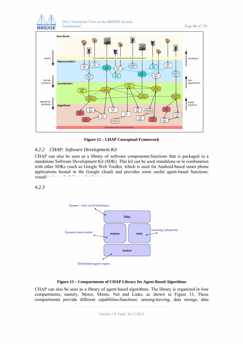
Version 1.0: Final 30.11.2013
D4.2: Functional View on the BRIDGE System Architecture Page 34 of 136
Figure 12 – CHAP Conceptual Framework
4.2.2 CHAP: Software Development Kit CHAP can also be seen as a library of software components/functions that is packaged in a standalone Software Development Kit (SDK). This kit can be used standalone or in combination with other SDKs (such as Google Web Toolkit, which is used for Android-based smart phone applications hosted in the Google cloud) and provides some useful agent-based functions: visualization, scheduling, calendaring.
4.2.3 CHAP: a Library/Repository of Agent-based Algorithms
memo
links
nets
motor
System – real world interfaces
Dynamic data modelLearning/adaptivity
Distributed agent engine
Figure 13 – Compartments of CHAP Library for Agent-Based Algorithms
CHAP can also be seen as a library of agent-based algorithms. The library is organized in four compartments, namely, Motor, Memo, Net and Links, as shown in Figure 13. These compartments provide different capabilities/functions: sensing/moving, data storage, data

Version 1.0: Final 30.11.2013
D4.2: Functional View on the BRIDGE System Architecture Page 35 of 136
processing, data presentation. In the following subsections we describe these functional compartments, which correspond to functional capabilities of a hybrid agent.
The Motor Compartment – Data acquisition from sensors, acting Motor is a compartment of the general framework which is responsible for physical/system resource management and administration (including data sensing/acquisition from sensors, and providing an execution engine/motoric system).
Depending on the context in which agents are going to be used, there are several Motors currently provided for a CHAP agent:
EmbedOS - an agent execution platform for embedded systems; it allows a CHAP agent to provide scheduling functions at OS-level;
Abbey - a multi-agent-based thread allocation system; it provides thread management (scheduling) at application level;
CAL – an agent-based messaging dispatcher component and simple context management system;
GroovyActors – an agent-based system for concurrent programming
The Memo Compartment – Data Storage Memo compartment of CHAP is used for data storage. Memo is a data storage function that facilitates system interoperability at data level.
Example Knowledge Representation / Context components provided by CHAP:
GAME1 – Generic Almende Model for Entities is a developed general data model for data storage;
GAME3 – this is an extension of GAME1 to cover event subscription and notifications, time passage and history of agents, and agent interaction capabilities.
The Nets Compartment – Data Processing, Learning and Reconfiguration Nets compartment is used for data processing functions, implementing business logic, i.e. the intelligence of the agent. This provides a set of algorithms processing of data stored by the data storage component, directs presentation of data to the user, or controls the motoric system. It consists of various planning, scheduling, and learning algorithms for knowledge extraction, machine learning, data mining, etc.
Example of developed components providing Nets functionality.
ESN (Echo-State-Network) is for pattern recognition;
ART and ARTMAP (Adaptive Resonance Theory) is a neural network-based unsupervised learning system for object recognition
KohonenNets (Self-Organizing Networks) is the implementation of Kohonen networks
The Links Compartment – System Interaction Links compartment is responsible for the interaction between agents and humans or between CHAP agents and other types of agents (e.g., AgentScape [] agents). It contains various visualization functions/primitives implemented by modules such as Graph, Timeline and Network; it also contains some user interaction interfaces for humans to provide inputs to the multi-agent system.

Version 1.0: Final 30.11.2013
D4.2: Functional View on the BRIDGE System Architecture Page 36 of 136
Examples:
Eve – a modular Human Interaction Agent offering calendar-based task management, distance calculations and time planning functions; supports communication via JSON-RPC
ASK/Paige – a personal agent providing decision support for emergency responders
Visualization Primitives Library consists of several functions: o GRAPH/GRAPH3D – Interactive Graph Visualization Functions o NETWORK – Interactive Network Manipulation Function o TIMELINE – Interactive Timeline Manipulation Function
4.2.4 CHAP as Agent Middleware Platform CHAP is not a generic middleware platform, but can be viewed as an agent middleware platform in a broad sense of the word: it provides several layers and exposes several standard services/functions on these layers, which can be instantiated or invoked as out-of-the-box components by other agents. See figure below for the mapping between the layers of a middleware and the various instantiations of CHAP projects onto this middleware.
EVE
MOTORConcurrency
LINKS
Generic Visualization Primitives
NETSMEMO
System – real world interfaces
Dynamic data model Learning/adaptivity
Agent Engine
Graph Graph3D Network Timeline
ScratchOS
Embedded Systems OS
ART/ARTMAP
ESNGAME1/MEMO
AdaptiveResonance Theory Echo State
Network
KOHONENNET
Self-Organization
ABBEYS
Groovy ActorsThread Pool
Communicating Agent Library
Agent Simulation
Concurrent Programming
Generic AlmendeModel for Entities
ASK
Data Synchronization
Cloud Services
Google App Engine
Communication
Web Services
SENSEIVO
CAL
Hadoop
CouchDB
Heuristics
Emerge
Figure 14 – A Functional View on the CHAP Agent Platform / Middleware
The relations between the CHAP layers and the typical layers of an ICT system architecture are shown in the figure below.
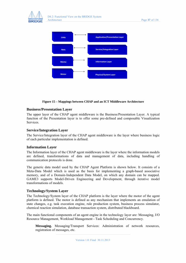
Version 1.0: Final 30.11.2013
D4.2: Functional View on the BRIDGE System Architecture Page 37 of 136
Application/Presentation Layer
Service/Integration Layer
Information Layer
Physical/System Layer
Links
Nets
Memo
Motor
Figure 15 – Mappings between CHAP and an ICT Middleware Architecture
Business/Presentation Layer The upper layer of the CHAP agent middleware is the Business/Presentation Layer. A typical function of the Presentation layer is to offer some pre-defined and composable Visualization Services.
Service/Integration Layer The Service/Integration layer of the CHAP agent middleware is the layer where business logic of each particular implementation is defined.
Information Layer The Information layer of the CHAP agent middleware is the layer where the information models are defined, transformations of data and management of data, including handling of communication protocols is done.
The generic data model used by the CHAP Agent Platform is shown below. It consists of a Meta-Data Model which is used as the basis for implementing a graph-based associative memory, and of a Domain-Independent Data Model, on which any domain can be mapped. GAME3 supports Model-Driven Engineering and Development, through iterative model transformations of models.
Technology/System Layer The Technology/System layer of the CHAP platform is the layer where the motor of the agent platform is defined. The motor is defined as any mechanism that implements an emulation of state changes, e.g. task execution engine, rule production system, business process simulator, chemical reaction simulation, database transaction system, distributed blackboard.
The main functional components of an agent engine in the technology layer are: Messaging, I/O Resource Management, Workload Management - Task Scheduling and Concurrency.
Messaging. Messaging/Transport Services: Administration of network resources, registration of messages, etc.

Version 1.0: Final 30.11.2013
D4.2: Functional View on the BRIDGE System Architecture Page 38 of 136
I/O Resource Management. Resource Management includes administration of data sources, data integration/mapping and data transformation.
Workload Management. Task Scheduling and Concurrency Services include: Administration of thread pools, task management policies, dynamic prioritization and coordination, etc.
4.3 AgentScape AgentScape is a distributed multi-agent system. It can connect a (large) number of hosts together, to deploy large-scale agent-based applications.
4.3.1 AgentScape Concepts AgentScape defines the following concepts: Host, Locations & Worlds to structure the system environment, as well as Services & Agents to perform application logic.
Hosts & Locations An AgentScape platform contains hosts and locations. A location can consist of a number of hosts. These hosts may be physically distributed, but they belong to a single administrative domain (the location).
Each physical host runs an instance of the AgentScape platform with a Host Manager Service. Optionally, some of the hosts can run a Location Manager Service, which performs the coordination of all the available hosts in the location. This is illustrated in Figure 16.
Figure 16 – AgentScape Platform
On the left we see three different instances of the AgentScape platform. Each are running a host manager, but one is also running a location manager. All hosts that are connected to this location manager belong to the same location, so they are effectively part of the same location (as shown on the right).
This distinction exists to separate administrative domains (locations) from the physical machines (hosts) that are part of the domain. Policies can be applied per host or per location.
Each host in AgentScape can run various (application) services, as well as hosting agents. Services are activated on start-up time, whereas agents can be started & stopped while the system is running.
Worlds In order for (distributed) hosts to find other hosts (and the location manager), AgentScape defines the concept of a World. A world is defined by a World Lookup Service, where all location and host managers are registered. Hosts can use this lookup service to find other hosts and location managers.

Version 1.0: Final 30.11.2013
D4.2: Functional View on the BRIDGE System Architecture Page 39 of 136
A lookup service may be a central node where all the addresses of the hosts are stored. It can also be a distributed service, but there is no fully functional implementation provided with the current release of AgentScape. The lookup service is a very simple process though, so it will be easy to make alternative implementations.
There is a default world lookup service available at http://lookup2.agentscape.org, which can be used by anyone. Each location that uses this lookup service runs in the “public” world. As a result, hosts can see (and be seen by) all other hosts that use the same lookup service.
Figure 17 – AgentScape Lookup Service
It is also possible to define a separate world, by running your own lookup service. Hosts and Locations can only contact others in their own world, so this allows for running isolated experiments or a separate (non-) public world (see Figure 17).
Agents Most applications on AgentScape will be built using the concept of agents. These agents are pieces of code that can interact with the AgentScape platform and other agents in order to achieve their (collective) goals.
Agents generally do not run as separate process, but are hosted by an AgentScape host. Each host can provide various kinds of agent servers that act as application servers for agents. Different implementation of agent servers exist (or can be made) for Java agents, native agents or anything more.
Agents can be started on a specific location in the world, though the actual host the agent will be running on is not visible to the agent. Where the agent is placed is automatically decided by the location manager process; it depends on the requirements the agent has (which services it needs) and which hosts are willing to accept this agent. The agent itself is not aware on which physical host it is running, but it only knows on which location it is.
Agent Migration If an agent decides that the current location is not meeting the demands of the agent (it may not be offering all the services the agent needs), an agent can make a migration request at its

Version 1.0: Final 30.11.2013
D4.2: Functional View on the BRIDGE System Architecture Page 40 of 136
location manager – which is a request to be moved to another location. If the location manager allows this, it will contact the location manager of the desired location and arrange a handover (migration) of the agent to the new location.
The runtime platform that hosts the agents is responsible for managing the life-cycle of the agent. If an agent needs to be migrated, it is suspended on the source location. The code and the state of the agent are (cryptographically signed and) transported to the remote location, where a suitable host is found to restart the agent.
Agent Services Each host can offer services to agents. The agents can use the host service broker to find out which services are available and can request a binding to the service. Services can be application specific (made by the application developer) or general purpose (AgentScape supplies directory, servlet and publish/subscribe services by default).
Each host defines a number of services that it will start, along with access rules. At the moment, the only access rules for services are:
Host only (service can be used by clients on this host)
Location only (service can be used by clients on this location)
World only (service can be used by any client in the entire world)
Because agents bind to a service using a secure connection, they can access services also when these reside on a remote machine: even on a different location or a different world, if the service allows it.
Services can not only be used by agents, but also by other services: if an application requires a servlet services for publishing information via HTTP, it can do so.
4.3.2 AgentScape Services AgentScape can provide a number of services through a combination of software-agents and services. As a reference to the services discussion in the remainder of this section, an overview of the current AgentScape Functional Architecture is provided:
Figure 18 – Functional View on the AgentScape Architecture

Version 1.0: Final 30.11.2013
D4.2: Functional View on the BRIDGE System Architecture Page 41 of 136
Secure Communication A connection-oriented encrypted communication mechanism between AgentScape kernels offers secure communication sockets to the middleware. On the application level agents are offered message-based communication on top of this infrastructure.
Agent Container Management Agents and their data are stored in agent containers. Containers support multiple code and data segments, allowing for multiple instances of the same agent, and allowing the agent to securely store private information.
Secure Agent Migration AgentScape supports secure migration of software-agents from one AgentScape location to another, by means of Agent Container Transfer.
Agent Runtime Environment AgentScape provides a so-called ‘Agent Server’ that provides a runtime environment for software-agents, enabling the agents to communicate with other agents and services, and access other middleware functionality such as migration and container-access.
Service Runtime Environment In addition to agents, AgentScape also provides a ‘service’ runtime environment, allowing developers to create applications consisting of both agents and services. Compared to agents, services cannot migrate and have different security policies associated to them.
Host Management AgentScape instances are managed internally by a Host Manager service, which configures the middleware and ensures that the instance is registered within the AgentScape location.
Location Management Within an AgentScape location, a Location Manager service configures the Host Manager services. The LM is also the main contact point for other AgentScape locations, for tasks such as agent migration.
Lookup Service The lookup service maintains low-level contact information on the AgentScape middleware services, agents, and application level services.
Blackboard service AgentScape applications can use a BlackBoard service to publish and subscribe to information in a shared space.
Web Service Gateway AgentScape provides managed access to external web services by means of providing web service proxies that communicate via a gateway.
Directory Service Applications in AgentScape can use a Directory Service to store and retrieve key-value based information, such as for example agent and service names, agent properties and capabilities, etc.

Version 1.0: Final 30.11.2013
D4.2: Functional View on the BRIDGE System Architecture Page 42 of 136
Logging Service Applications may use the application level logging service to log messages for later analysis and debugging purposes.
Secure Data Space AgentScape provides several application level components (agent libraries and domain manager agents) that work together to provide secure data storage and retrieval, based on the BlackBoard infrastructure.
Message Queue Service The MQ Service offers applications a channel based communication method as an alternative to the internal agent-agent communication mechanisms.
External APIs AgentScape offers APIs on all levels of the middleware to enable integration with other frameworks:
o AOS Sockets: low level sockets that allow direct access to middleware services
o AgentScape admin API: Manage AgentScape configuration and applications.
o AgentScape API: Communicate with agents and services.
BRIDGE Services For BRIDGE, there is one extra application service, which is the S2D2S service. This specific service uses the AgentScape blackboard service for storing data items in topics (in a publish/subscribe way). It also makes use of the AgentScape servlet service to provide access to the service via HTTP(s).
The S2D2S service can be accessed from remote processes via JSON-RPC (it uses a specific servlet that implements this). Processes in BRIDGE can use the JSON endpoint directly2.
Access to this service is also possible via LinkSmart. The machine that runs the S2D2S service also runs a LinkSmart proxy which communicates with LinkSmart on one side (using web services) and JSON-RPC on the other side.
4.4 Dynamic Expertise Integration Network (DEIN) The Dynamic Expertise Integration Network (DEIN) is a generic framework, a suite of software libraries and design methods that facilitate creation of solutions for situation assessment in a relevant class of domains. A detailed description of the DEIN framework can be found in D07.2 – DEIN Requirement Specification and Semantic Expertise Structure. The main features of the DEIN framework are:
Easy implementation of information flows between distributed stakeholders (experts, observers and decision makers) in complex crisis management, collaborative situation assessment in coalition operations (maritime security, peacekeeping, etc.).
The right people and automated processes get the right information at the right moment in time.
2 http://bridge.d-cis.nl:8008/Name/S2D2S/jsonrpc

Version 1.0: Final 30.11.2013
D4.2: Functional View on the BRIDGE System Architecture Page 43 of 136
Integrate arbitrary automated solutions if possible/acceptable, but keep the humans in the loop wherever necessary.
Exploit rich information without creating information flooding.
DEIN introduces the OntoWizard, a tool that allows very easy installation and configuration of DEIN-based solutions; users can configure the system themselves (no need for technical knowledge).
Use standard computing and communication infrastructure.
DEIN is relevant for large scale analysis problems involving many specialists and automated processes with heterogeneous capabilities, each analysing specific aspects of the domain (heterogeneous domain knowledge). In such settings assessments about critical events are obtained through exchange of specific estimates/conclusions of the involved experts; in principle, a DEIN-based system consisting of many experts and automated processes provides a “mapping” between large quantities of heterogeneous information and conclusions about the relevant states in the domain.
DEIN achieves collaborative information processing through weak coupling of very heterogeneous analysis services belonging to different stakeholders, which are spatially distributed and belong to different organizations. By explicitly taking into account the capabilities and needs of experts or automated processes (i.e. provided services), a DEIN-based system finds all relevant analysts and information sources for a given problem and maintains complex and even dynamic information flows.
4.4.1 DEIN Wrapper Technology DEIN makes use of the Dynamic Process Integration Framework (DPIF) wrapper technology which (i) makes very heterogeneous services composable, (ii) supports reliable service composition through service discovery and (iii) keeps track of information flow in complex collaborative systems (Pavlin, Kamermans & Scafes, 2010).
In DEIN each local process (human or machine-based) is encapsulated by a module which is implemented through a software agent (a DPIF agent). The agents provide a uniform interface between different local processes involved in collaborative information processing workflows. A key feature of the DPIF agents is asynchronous, data-driven processing in complex workflows. This is achieved through a combination of weakly coupled processes. Each module consists of at least two basic processes implemented through asynchronous threads communicating via a local blackboard (see Figure 19).
The Communication Engine is a thread which provides inter-module communication, collaboration and negotiation capabilities. Communication Engines in different agents establish workflows between local processes in different agents by executing service discovery and negotiation. Negotiation is based on the Contract Net Protocol, a task sharing protocol in multi agent systems3. The Processing Engine, on the other hand, is a thread which encapsulates arbitrary automated or human based inference.
3 http://en.wikipedia.org/wiki/Contract_Net_Protocol

Version 1.0: Final 30.11.2013
D4.2: Functional View on the BRIDGE System Architecture Page 44 of 136
Figure 19 – Interaction between agents providing heterogeneous processing services
Both agents use identical communication engine. However, agent 1 encapsulates automated processing while agent 2 integrates human-based processing.
A human expert is integrated into a DPIF-based analysis system with the help of a dedicated software agent, an assistant that (i) collects all information relevant for the expert, (ii) disseminates the expert opinion/estimates and (iii) triggers the expert’s attention. Such an agent continuously runs on an arbitrary server. Each expert communicates with the personal DPIF assistant via a graphical user interface which can run on arbitrary networked computers and PDAs (seeFigure 20). Thus, DPIF services are globally accessible.
Figure 20 – A Graphical User Interface supports communication between the expert and his (or her) DPIF agent
In principle, arbitrary automated reasoning techniques can be integrated into the DPIF. An example of a theoretically sound collaborative inference system based on the DPIF is the Distributed Perception Networks framework (DPN), a modular approach to Bayesian inference (Pavlin et al., 2010). DPN is a fully automated DPIF variant that supports exact decentralized inference through sharing of partial inference results obtained by running inference processes on local Bayesian networks in different collaborating DPN agents.
DPIF agents can autonomously form workflows in which heterogeneous processes support collaborative analysis (see example in Figure 21). The DPIF implements advanced negotiation mechanisms, which support automated creation of connections between experts and automated processes by using multiple criteria and advanced protocols (Badica & Scafes, 2011).

Version 1.0: Final 30.11.2013
D4.2: Functional View on the BRIDGE System Architecture Page 45 of 136
Figure 21 – A simplified example from Crisis Management
This simplified Crisis Management example illustrates the information flow between different collaborating experts and automated tools that are integrated via DPIF agents (blue rectangles).
4.4.2 The OntoWizard Tool An integral element of DEIN is OntoWizard, a combination of tools, methods and procedures, which supports tractable definition of services, which are indispensable for creation of workflows. OntoWizard allows decentralized management of large scale processing capabilities. The system automatically generates rigorous service ontologies encoded in OWL, which are used by DEIN to establish collaboration. DEIN ontologies are used merely for service discovery and creation of communication channels. Therefore, the DEIN is using types of relatively simple service ontologies whose main purpose is to make analysis services easily composable and to facilitate runtime collaboration between experts/processes:
The global service ontology merely captures service descriptions, the semantics and syntax of messages used for (i) service invocation and (ii) dissemination of service results. This ontology is used for the alignment of the semantics and syntax of service descriptions at design time.
Local task ontologies coarsely describe relations between different types of services supplying different types of information. In principle, they describe which types of services provide inputs to the function used by a specific service. These relations reflect the local knowledge of each processing module/expert. Local ontologies are key to runtime creation of workflows based on service discovery.
The relations between services captured in local ontologies correspond to the local domain knowledge of the experts or domain models of specialized automated processes; each expert
CA1
Chemical Adviser 2
CA1
Factory Rep.
CA1
COPI
CA1
ROT-decision makers
ARGOS
CA1
Chemical Adviser 1
ARGOS
CA1
Measurement-team 1
CA1
BOTMI
CA1
Health Expert 1
CA1
DCMR Meldkamer
AR GOS
CA1
Field Inspector 1CA1
Staff Member 1CA1
Staff Member 2CA1
Staff Member N
AR GOS
CA1
Measurement-team 2
CA1
Botmi expert N
CA1
Botmi expert 1
CA1
Field Inspector 2
ARGOS
CA1
ARGOS
ARGOS
CA1
GDM
CA1
Chemical Adviser 2
CA1
Factory Rep.
CA1
COPI
CA1
ROT-decision makers
ARGOS
CA1
Chemical Adviser 1
ARGOS
CA1
Measurement-team 1
CA1
BOTMI
CA1
Health Expert 1
CA1
DCMR Meldkamer
AR GOS
CA1
Field Inspector 1CA1
Staff Member 1CA1
Staff Member 2CA1
Staff Member N
AR GOS
CA1
Measurement-team 2
CA1
Botmi expert N
CA1
Botmi expert 1
CA1
Field Inspector 2
CA1CA1
Chemical Adviser 2
CA1CA1
Factory Rep.
CA1CA1
COPI
CA1CA1
ROT-decision makers
ARGOSARGOS
CA1CA1
Chemical Adviser 1
ARGOSARGOS
CA1CA1
Measurement-team 1
CA1
BOTMICA1CA1
BOTMI
CA1
Health Expert 1CA1CA1
Health Expert 1
CA1
DCMR Meldkamer
AR GOS
CA1CA1
DCMR Meldkamer
AR GOSAR GOS
CA1CA1
Field Inspector 1CA1CA1
Staff Member 1CA1CA1
Staff Member 2CA1CA1
Staff Member N
AR GOSAR GOS
CA1CA1
Measurement-team 2
CA1
Botmi expert NCA1CA1
Botmi expert N
CA1
Botmi expert 1CA1CA1
Botmi expert 1
CA1
Field Inspector 2CA1CA1
Field Inspector 2
ARGOS
CA1
ARGOS
ARGOSARGOS
CA1CA1
ARGOS
ARGOS
CA1
GDM
ARGOSARGOS
CA1CA1
GDM

Version 1.0: Final 30.11.2013
D4.2: Functional View on the BRIDGE System Architecture Page 46 of 136
knows which services are needed in order to provide a certain service. This assumption is realistic in a significant class of applications and allows tractable solutions with minimal ontological commitments. Thus, by using OntoWizard tool, each expert can describe relations between the provided and the needed services. Such a description is translated into the local ontology that is used by the corresponding DPIF assistant for integrating the expert/process into a workflow. Because of this, systems exploiting complex relations between services can be built in a collaborative way, without any centralized configuration/administration authority.
The knowledge in DEIN is captured in local ontologies. Each DEIN agent has a local ontology which captures (i) the types of services that the expert provides and (ii) the required information for each type of services.
Each type of knowledge is specified through a combination of three elements:
1. a verbal description and keywords 2. a description of the service invocation request 3. a description of the service outputs.
Points (2) and (3) are based on a set of objects that represent atomic information types with clearly defined semantics and format.
4.5 WISE Integration Tool The WISE Integration tool is part of the WISE Family and is a generic platform designed to provide training in any domain ranging from live training via virtual to constructive training. The WISE Family comprises of three major parts:
Customer Solutions WISE Training Platform WISE Connectivity
For the FRITS concept, only WISE Connectivity (illustrated by the red box in the hub figure below) is used for integration. Today's work becomes more and more complex. The world is changing ever faster, and a workplace can be located to any environment, in different continents and countries and at
different times. The amount of unforeseen circumstances that affect how a user can act and what decisions a user takes increases, which requires that the training system is changed at the same rate.
Version 1.0: Final 30.11.2013
D4.2: Functional View on the BRIDGE System Architecture Page 47 of 136
When talking about training the focus should be on what the expectations are set in an organization and its ability to live up to those expectations. Often the focus is on what technology is behind in order to realize a training system rather than what the training process actually demands of the organization.
In order to train the same way as you work, our tools supports a scenario-based training process. This process is based on what you have to achieve and what kinds of problems you are expected to solve to deal with an incident or an assignment in a given time. We believe that this technique provides better overall training value.
Our training services are based on the customer always be able to adapt to changing expectations, new training tools and new procedures and instructions in the organization's defined training goals.
MeTracker will handle these requirements, and be part of the integrated solution.
Learning Cycle Exercise Management Before you can start training, you have to define your training needs and the goals to be achieved during training. This definition should be done by experts in the field of training and be based on good practice and experience from previous exercises similar to the current exercise as planned.
Review of relevant procedures must also be maintained so that the trainees as individuals and as a group understand the expectations of those goals. All these preparations are being made in the MeTracker tool as seen below. Here you can create a baseline scenario description, and the training goals of the scenario.
Run-time Exercise and Evaluation Management During an exercise it is possible to monitor the events taking place and see how the trainees act and react to these events. In the exercise, observations are made both by those who manage the exercise and by those acting in the exercise. These observations are added to the evaluation and are built dynamically during the exercise and can also be created after the exercise.
Evaluation of the trainees’ development can be continuously monitored in order to constantly keep track of whether the stated training goals are met or not. This helps to not be extradited to make this evaluation only after the exercise ended. Exchange of information between the trainees and the exercise management is important in the learning process.
Aggregated and individual evaluation is done to enhance the learning process. Both the scenario objectives fulfilled and those that are missed can be exemplified and discussed with the trained. At this point, the experts who helped to create scenarios play a major role. It is possible to export data for either the entire exercise or for individual achievement that can be handed to the trainees to take part of the evaluation at home after the end of exercise
AKKA will handle this requirements, and be part of the integration

Version 1.0: Final 30.11.2013
D4.2: Functional View on the BRIDGE System Architecture Page 48 of 136
4.5.1 WISE Connectivity
Figure 22 – WISE Connectivity
In order for an integration between two or more training system to be successful, the training value generated by the integration has to be greater than the value of each training system. In the world we live in the training requirements changes from day to day and time you have to integrate these requirements into existing or new systems decreases gradually.
The solution to this problem is to emphasize integration methodology to a higher level and move towards an approach where training systems need not be modified to meet the new requirements. This we realize with a generic platform for integration that allows connecting the systems to a common environment where we create information flows to and from every system that we choose to connect. This happens regardless of any architecture systems use and regardless of the communication standard used.
The information flows that are set can be checked in detail, allowing features such as filtering, blocking and transformation.
4.5.2 BRIDGE Training Design A main area of interest will be to develop a training system that integrates a defined learning methodology, the technologies supporting information gathering and handling during the training and existing operational systems into one common training environment. The main purpose of this training system will be to support the improvement of the quality of emergency response and crisis management with particularly focus on collaboration and coordination between different organizations from different disciplines and countries. Training is normally divided in Live-, Virtual and Constructive (LVC) Training:
Live Training is real-time live exercises with use of instrumentation to collect adequate information needed to support an extensive evaluation process.
In a Virtual Training environment, simulators operating on a virtual terrain take the place of operational systems and can be linked to expand the training exercise. Virtual Simulations, which are synthetic environments that include the replication of operational equipment/ and operational environmental conditions; allows for the sharing of a common environment which multiple users can access; and supports interactions with simulated entities (including objects, avatars, and equipment) that mirror, those that would occur in the real world.
Constructive Training uses real human inputs and/or computers to simulate different operational elements. This enables multiple echelons of command and staff to execute their normal operational tasks in an unconstrained exercise environment. Semi-automated Forces/ Organizations are one example of constructive simulations; Gaming models are another example.
By combining the different training methods above, one enable organizations to interact with one another to conduct a coordinated operation as though they were physically together on the same ground. The above description is based on ‘Definition of LVC’ from ‘The Office of Naval Research’ with ref ONR BAA Announcement #11-005.

Version 1.0: Final 30.11.2013
D4.2: Functional View on the BRIDGE System Architecture Page 49 of 136
The BRIDGE Training System (FRITS) will be based on the already established learning and training methodology from CTAS, supported by information- gathering and assembling technology from CTAS and SAAB Training Systems. The system shall be a module that is used for planning, executing and evaluating scenario- and collaboration-oriented training activities. This is referred to as experienced-based training.
The training system will also be used to document a number of the activities done in the domain analysis.
Learning and Training Methodology The learning and training methodology of CTAS is divided into five main activities, each with a number of sub-activities as shown in Figure 23.
Figure 23 – Learning and Training Methodology
Analyse Phase: The main objective for this phase is to define training objectives based on the actors, existing emergency plans, and experiences from earlier training sessions and real operations. Another important activity in the Analyse phase is to establish and acknowledge the process for the evaluation of the training activities, and assure that the experiences are integrated in the participating organisations.
Planning Phase: Based on the training objectives, the scenario will be defined and further detailed into a storyboard and an execution plan. The next step will be to secure and define the required resources (personnel and materiel) to execute the exercise. The final activity in the planning phase is to assure the right competence both for the training facilitators/evaluators as well as the trained personnel.
Execution phase: Based on the defined scenario, the training environment will be established and the exercise executed. The exercise could be Live, Virtual or Constructive or a combination of these. During the exercise, well trained observers will assure that important observations are documented and learning processes are managed.
Evaluation phase: Based on received information from different sources, the evaluation team will analyse and compile the information related to the defined objectives. Finally

Version 1.0: Final 30.11.2013
D4.2: Functional View on the BRIDGE System Architecture Page 50 of 136
the evaluation process will be prepared and executed based on well-established learning processes.
Lessons learned: The objective of this phase is to assure that relevant experience from the exercise will be transferred to relevant organisations and that emergency plans/other directives are reviewed and updated if needed.
Information Gathering and Handling To properly design, support, and evaluate training operations, real data from past operations and analyses of weak spots in those operations will be used as input to the training system. This data may also be used to design and produce relevant and realistic training scenarios. Furthermore, real data from past operations could also be used to benchmark training results against real operations metrics and performance indicators. Different variants of training approaches can be compared with each other in terms of effectiveness. Finally, an important step is to translate the training experience and results back to guidelines, workflow configurations, that can be used to prepare, brief and support emergency response operations in real-time.
To optimize the evaluation, the information gathering and the handling of all this information is extensive. To support this activity, an information-gathering and handling system must be further developed. SAAB Training Systems existing AKKA system will be the baseline for further development of such a system.
Figure 24 – Information Gathering and Handling
The Exercise Management function includes the analysis and planning phases as described earlier. It also includes the Strategic function of the exercise control during the exercise.
The Exercise Lead function includes the Local Management placed close to the training environment. It also includes the special developed on site supporting tools that collects the relevant information from the training environment and the participants.

Version 1.0: Final 30.11.2013
D4.2: Functional View on the BRIDGE System Architecture Page 51 of 136
The Central Storage function obtains the information from the Exercise Management and the Exercise Lead function. The Central Storage function also obtains information from relevant operational systems in use by the participants. All this information is then handled to assure relevant evaluation information for use during the evaluation and Lessons Learned phase.
The objective in BRIDGE is to continue to develop and optimize this integrated training environment to optimize exercises with the aim to find and improve the operation of intra- and interagency as well as cross border crisis. Also, using training as a research tool will help the project search for optimal solutions applied to a real operational context.
4.6 Summary Taking the structural overview on the BRIDGE middleware architecture into account, Figure 25 provides a graphical overview of the components that are (partly) addressed by partners’ technologies or will be developed within the scope of the respective technology.
Figure 25 – Use of existing Baseline Technology for the BRIDGE Middleware
AgentScape services have been extended to implement orchestration services such as Triggering&Eventing and Workflow Management. Also, the platform provided the core Publish&Subscribe Service together with the Shared Dataspace. In addition, the BRIDGE middleware exploits the AgentScape implementation of security and trust mechanisms.
CHAP as an agent-based platform provides functionality for dealing with information and resources. It will be mainly applied to the services that deal with resource and information management.
LinkSmart middleware already provides networking and discovery functionality and implementation of encrypted and trusted communication. A Media Streaming Service and Network Information Service will be developed as LinkSmart components.

Version 1.0: Final 30.11.2013
D4.2: Functional View on the BRIDGE System Architecture Page 52 of 136
DEIN will basically contribute its messaging approach to the Messaging Service, which is integrated with the accordant CHAP implementation.
The main goal of WISE is not to provide middleware service but to serve as a flexible interface to the BRIDGE training Concept FRITS. However, the existing Transformation functionality has been exploited and integrated with the BRIDGE middleware.
Version 1.0: Final 30.11.2013
D4.2: Functional View on the BRIDGE System Architecture Page 53 of 136
5 BRIDGE System Architecture This chapter describes the software architecture of the BRIDGE middleware on a general level before going into detail using the views and perspective approach described earlier.
5.1 The Middleware Concept The concept of ‘middleware’ in distributed systems is often taken to mean ‘the software layer that lies between the operating system and the applications on each site of the system’ (Krakowiak, 2003). Another characterization in terms of the ISO OSI stack (Day and Zimmerman, 1983) is that middleware provides protocols that run on top of the transport layer and that provides services to the application layer (Tanenbaum and Van Steen, 2007, p. 123) as shown in Figure 26.
In a casual way, a middleware represents the intersection of the things that network engineers do not want to do with the things that application developers do not want to do. The decision in the BRIDGE project to build a middleware for developers of emergency response information technology funds on four major arguments:
A middleware is mostly invisible. The developer does not really see middleware, but the web services it provides and the information flow that middleware makes possible. Developers are aware of software packages at the top level in a logical view, such as a web application, and packages that exist at the bottom level, such as databases and the operating system. The middle part, that ties everything together, can seem less concrete and identifiable. This is part of why middleware is hard to define.
A middleware provides a standard way of doing things. A software developer could design and build his own application servers, database connection drivers, authentication handlers, messaging systems, etc. However, these would not be easy to build and maintain. It is much easier to make use of middleware components that are built according to established and especially open standards. In a middleware, these standards take the form of libraries of functions that the developer’s call through well-defined application programming interfaces (APIs).
A middleware ties together parts of complex systems. Middleware keeps information moving through complex applications. One of its primary tasks is to connect systems, applications, and databases together in a secure and reliable way. A middleware enables software developers to tie together systems that were built by different people, at different times, without having to reconstruct everything from scratch. One of the most powerful approaches is a service-oriented architecture that allows for the integration of software applications developed at different times, by different organizations, and even communicating via different protocols. Developers do not have to rewrite them to speak one consistent language.
A middleware lets developers focus on other things. With middleware taking care of all the invisible functions, a software developer can concentrate on building software to solve your business problems and fulfil your customers’ needs. A middleware may be mostly invisible, but it keeps things running so a lot of developers, managers and customers can rely on it.
The need for middleware for the BRIDGE project stems from the increasing growth in the number of applications and information technology in the area of emergency response, and in the customizations within those applications. A BRIDGE middleware needs to move a set of core services and data from their multiple instances across several different applications into a centralized institutional offering. This central provision of service eases application

Version 1.0: Final 30.11.2013
D4.2: Functional View on the BRIDGE System Architecture Page 54 of 136
development, increases robustness, assists data management, and provides overall operating efficiencies. Furthermore, the BRIDGE middleware needs to provide transparency in various ways such as location transparency, access transparency, or failure transparency (ISO, 1995).
Figure 26 – Middleware Layer
Schmidt (2002) elaborated a more detailed insight into the middleware layer and divided into the layers Host Infrastructure Middleware, Distribution Middleware, Common Middleware Services and Domain-Specific Middleware as shown in Figure 27.
Figure 27 – Generic Middleware Stack
The Host infrastructure Middleware encapsulates and enhances native operation systems, and abstracts from sockets and provides higher-level abstractions (such as active objects), e.g., a virtual machine such as the Java Virtual Machine. The Distribution Middleware defines higher-level distributed programming models like for example CORBA or Web Services. The Common Middleware Services constitute higher-level domain-independent components for tasks such as event notification or logging. The Domain-Specific Middleware is tailored to specific system domain such as avionics or radar processing and manages issues like navigation management. Figure 27 also displays the areas of the generic middleware stack that the BRIDGE middleware covers.
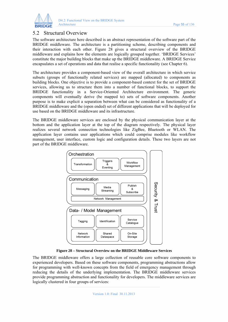
Version 1.0: Final 30.11.2013
D4.2: Functional View on the BRIDGE System Architecture Page 55 of 136
5.2 Structural Overview The software architecture here described is an abstract representation of the software part of the BRIDGE middleware. The architecture is a partitioning scheme, describing components and their interaction with each other. Figure 28 gives a structural overview of the BRIDGE middleware and explains how the elements are logically grouped together. ‘BRIDGE Services’ constitute the major building blocks that make up the BRIDGE middleware. A BRIDGE Service encapsulates a set of operations and data that realise a specific functionality (see Chapter 6).
The architecture provides a component-based view of the overall architecture in which service subsets (groups of functionally related services) are mapped (allocated) to components as building blocks. One objective is to provide a component-based context for the set of BRIDGE services, allowing us to structure them into a number of functional blocks, to support the BRIDGE functionality in a Service-Oriented Architecture environment. The generic components will eventually derive (be mapped to) sets of software components. Another purpose is to make explicit a separation between what can be considered as functionality of a BRIDGE middleware and the (open ended) set of different applications that will be deployed for use based on the BRIDGE middleware and its infrastructure.
The BRIDGE middleware services are enclosed by the physical communication layer at the bottom and the application layer at the top of the diagram respectively. The physical layer realizes several network connection technologies like ZigBee, Bluetooth or WLAN. The application layer contains user applications which could comprise modules like workflow management, user interface, custom logic and configuration details. These two layers are not part of the BRIDGE middleware.
Figure 28 – Structural Overview on the BRIDGE Middleware Services
The BRIDGE middleware offers a large collection of reusable core software components to experienced developers. Based on these software components, programming abstractions allow for programming with well-known concepts from the field of emergency management through reducing the details of the underlying implementation. The BRIDGE middleware services provide programming abstraction and functionality for developers. The middleware services are logically clustered in four groups of services:

Version 1.0: Final 30.11.2013
D4.2: Functional View on the BRIDGE System Architecture Page 56 of 136
Orchestration Communication Data- and Model Management Security & Trust The Middleware Services represent globally available functionality shared by all BRIDGE applications, and possibly external systems/actors. The internal structure of each component is determined by a design derived from the related set of requirements and hence determined by specific project work packages. Chapter 6 provides a more detailed view on the above enumerated BRIDGE middleware services from a functional perspective. The following subsections provide an overview on the purpose of the middleware services.
5.2.1 Orchestration Orchestration services provide support for the composition of services and workflows. The main services are:
Transformation: Provides generic format and structure transformation services.
Triggers & Eventing: An event management subsystem, providing event channels, event taxonomies (types), and event log and history (based on extended LinkSmart).
Workflow Management: Definition, storage and sequencing of activities and tasks (possibly based on standard workflow models). Supports the sharing and re-use of workflow plans.
5.2.2 Data- and Model Management Data- and Model Management services support the acquisition, storage and exchange of data, services and models emerging from diverse sources (sensors, systems, databases, public, experts, colleagues, etc.) on the fly. The main services are:
Tagging: Provides functions needed for the annotation of any identifiable BRIDGE object (first responders, victims, buildings, data). This includes tagging with various sensor devices.
Identification: Supports the unique identification of BRIDGE resource (actors, tasks, devices, etc.). Provides functionality to register and query resources.
Service Catalogue: Provides access to BRIDGE middleware services as an entry point.
Network Information: Provides information about the infrastructure objects/topologies/resources.
Shared Dataspace: Provides a persistent data space for sharing and distribution among multiple clients.
On-Site Storage: Provides access to large-sized data without going over the Internet and thus, with shorter response times.
5.2.3 Communication Communication services provide functionality enabling distribution of data as well as invocations of services. The main services are:

Version 1.0: Final 30.11.2013
D4.2: Functional View on the BRIDGE System Architecture Page 57 of 136
Messaging: Allows sending messages to actors based on their role, location, etc. Also support for broadcast messages to a certain group of receivers (e.g. all fire-fighters in an area).
Media Streaming: Provides service for streaming media over the network.
Publish & Subscribe: implements a message-oriented communication paradigm to provide greater network scalability and more dynamic network topology
Network Management: provides functionality to change networks topology
5.2.4 Security and Trust Aspects of security and trust do not represent a focal point of research in the BRIDGE project as explicitly stated in the project description of work (see section 1.1.2 of BRIDGE’s DoW). However, the BRIDGE project addresses these aspects by exploiting the LinkSmart concepts and technology developed in the HYDRA project (funded by the European Commission). All aspects related to privacy are fully described in deliverable D12.1 – Privacy Protection and Legal Risk Analysis.
The BRIDGE middleware provides security, trust and privacy as a combination of guidelines, models, and supporting technologies including standards for Privacy Level Agreements, Trust and Cryptography.
Privacy: is handled by design. Message-related services provide functionality for hiding the identity of the sender, hiding the contents of a message or hiding the recipient of a message.
Trust: implements an assessment of the trustworthiness of an entity according to a given trust model.
Cryptography: provides standard cryptographic operations for protecting confidentiality, integrity and authenticity of messages.
Version 1.0: Final 30.11.2013
D4.2: Functional View on the BRIDGE System Architecture Page 58 of 136
6 The Functional View The functional view of a software architecture defines the architectural elements that deliver the system’s functionality. The view documents the system’s functional structure that demonstrates how the system will perform the functions required of it. According to Rozanski and Woods (2005), the functional structure model of the Functional View typically contains functional elements, interfaces, connectors and external entities:
Functional Elements constitute well-defined parts of the runtime system that have particular responsibilities and expose well-defined interfaces that allow them to be connected to other elements. A functional element can be a software component, an application package, a data store, or even a complete system.
Interfaces are specifications, defining how the functions of an element can be accessed by other elements. An interface is defined by the inputs, outputs, and semantics of each operation offered and the nature of the interaction needed to invoke the operation.
External Entities can represent other systems, software programs, hardware devices, or any other entity the system communicates with.
The functional view funds on the elicitation of a set of requirements and according service, which have been identified in the process of domain analyses and in architecture workshops. Further, the requirements evolving from the different technologies provided by different partners influence the functional view.
The following subsections introduce the services and components of the BRIDGE system as the core architectural elements in detail. They provide an overview on what purpose and main functionalities each component serves, and document what requirements they address.
6.1 Orchestration Orchestration services provide support for the composition of services and workflows. The main services are:
6.1.1 Transformation The Transformation service provides generic format and structure transformation services. It is not meant to interpret data but only do pure syntactical transformation. Such a transformation could be conversion between media encodings or protocol conversion e.g. WS to ZigBee. Such a service increases collaboration possibilities between agencies as they may build on different technologies or equipment and would make information exchange thus impossible. This service also protects from errors made due to improper interpretation of data.
Main Functionalities
registerFormat: Registers a specific encoding or structuring of data. registerFormatForAgency: Registers that an agency wishes to receive data in specific
format. transformData: Transforms the provided input data to a given output format.
Version 1.0: Final 30.11.2013
D4.2: Functional View on the BRIDGE System Architecture Page 59 of 136
Addressed Requirements ID Summary
BRIDGE-143 The mesh network shall provide bridges for the eTriage bracelets
BRIDGE-156 The system shall process multimedia information collected during an emergency incident (as a first step) received from social networks.
BRIDGE-169 Emergent interoperability
BRIDGE-296 he BRIDGE system shall be able to transport messages between nodes across different networks
BRIDGE-356 The Workflow Service requires a standards-based interaction protocol between involved middleware platforms
6.1.2 Triggers & Eventing The Triggers & Eventing service represents an event management subsystem, providing event channels, event taxonomies (types), and event log and history. Its main functionality is to inform interested parties in abnormalities of the environment or observed entities and allows them to infer how the current state has been reached. It may also include functionality that triggers a specific number of services that are designated to deal with specific changes or that have to start after a defined event occurs. More generally speaking this system allows to specifically deal with state changes that are of interest or are relevant.
Main Functionalities
registerState: This is mostly domain knowledge but has to be explicitly provided to the system.
registerInterestedParty: Provides the system with the knowledge where to forward this information.
createChannel: Collects a number of similar events and parties into a shared channel. Trigger: Informs the requested parties about the specified state change.
Addressed Requirements
ID Summary
BRIDGE-117 The triage system should trigger event of deteriorated vital values
BRIDGE-213 Events should be propagated in the network based on a Publish-Subscribe mechanism.
BRIDGE-275 The system shall offer a publish/subscribe and event API for triage events
BRIDGE-372 The GUI should allow to jump in time, to see also historic aggregation results/sub-events
BRIDGE-373 The GUI should show sub-events in a structured manner and with additional information (included items etc.)

Version 1.0: Final 30.11.2013
D4.2: Functional View on the BRIDGE System Architecture Page 60 of 136
6.1.3 Workflow Management Definition, storage and sequencing of activities and tasks (possibly based on standard workflow models). Supports the sharing and re-use of workflow plans. Also enables the harmonization and fusion of workflows from different agencies e.g. based on BRAWL. This enables to have an overall picture of independent activities that are carried out with regard to specific tasks. Using the harmonization capabilities it is also possible to define inter-agency dependencies between workflows and tasks and have the engine inform about possible delays that would affect unaware parties. The Workflow Management greatly leans on the Triggers & Eventing service.
Main Functionalities
composeWorkflow: Allows creating a new workflow or connecting already provided workflows.
loadWorkflow: Loads the workflow from a document already containing a workflow in some standard formatting. Transformation service may be used to deal with incompatibilities.
startWorkflow: Instantiates a specific workflow and starts observing relevant dependencies and state changes.
informWorkflow: Allows to provide third party information relevant for a workflow into the system. This may also be done by referencing the Shared Dataspace.
Addressed Requirements
ID Summary
BRIDGE-155 The Workflow service should have access to ontology storage/retrieval functionality
BRIDGE-188 The Workflow Service requires a standards-based interaction protocol between involved middleware platforms
BRIDGE-214 Victims should be trackable in the workflow
BRIDGE-268 Probing workflows to make correspondences.
BRIDGE-281 Workflows and restrictions need to be flexible to allow for changes and unexpected events in working practices.
6.2 Data- and Model Management Data- and Model Management services support the acquisition, storage and exchange of data, services and models emerging from diverse sources (sensors, systems, databases, public, experts, colleagues, etc.) on the fly. The following paragraphs describe the main services.
6.2.1 Tagging The Tagging service provides functions needed for the annotation of any identifiable BRIDGE object (first responders, victims, buildings, data). This includes tagging with various sensor devices. These tags can be any types of relevant pieces of information. The Tagging service may also be used as a way of communication but instead of providing the intended recipient the data is attached to the target it describes. This way whoever encounters the target receives all messages left in relation with it. These tags are accessible by all stakeholders by simply querying the identifier e.g. through the Shared Dataspace. Tagging also includes tagging with
Version 1.0: Final 30.11.2013
D4.2: Functional View on the BRIDGE System Architecture Page 61 of 136
various sensor devices this way providing continuous information flow rather than momentary observations.
Main Functionalities
addTag: Adds an information tag to an object. addTaggingSource: Registers a service (e.g. a sensor) as source of tags for this object. retrieveTags: Returns all tags provided for a specified identifier.
Addressed Requirements
ID Summary
BRIDGE-110 The system shall provide for directly addressing and communicating with any connected triage tag
BRIDGE-175 The BRIDGE system shall allow the first responders to annotate/tag resources. Rescue personnel is capable of identifying patients
BRIDGE-295 The triage tagging devices (e.g. bracelets) can be addressed to receive commands
BRIDGE-324 A list of victims around given position, with given radius, should be exposed somehow. For each victim give the latest sensor readings too, possibly in the same one answer
BRIDGE-337 Tagging of resources should go beyond common properties and include situated and contextual properties
6.2.2 Identification The Identification service supports the unique identification of BRIDGE resources (actors, tasks, devices, etc.) based on arbitrary attributes or persistent identifiers (provided by the LinkSmart IdentityManager). Attributes can be any pieces of information as owner, location, service provided or other distinguishing features. The service provides functionality to register and query resources using the specified attributes therefore finding all types of resources only by knowing their relevant feature. This can be extremely useful to filter the vast amount of resources available at an emergency site. In order to ensure privacy it is possible to set whether attributes are publicly announced, are only returned on request or are completely hidden.
Main Functionalities
registerResource: Registers a resource into the system and attaches the provided attributes to it.
getResourceByAttributes: Returns resources that have the requested attributes publicly announced.
queryResourceByAttributes: Explicitly queries resources that hold the provided attributes. These resources can than decide whether they respond.

Version 1.0: Final 30.11.2013
D4.2: Functional View on the BRIDGE System Architecture Page 62 of 136
Addressed Requirements
ID Summary
BRIDGE-124 The first responders should be able to send resource information to the command post. Victims should be trackable geographically
BRIDGE-175 First responders should be able to receive resource information of a specified resource.
BRIDGE-210 The BRIDGE system needs to transmit resource allocation replies and resource status updates from the field to the command post. The system shall allow the user to allocate a set of resources to a specific task and location, using a map-based allocation process.
BRIDGE-227 The BRIDGE system shall make the command post aware of any changes concerning the resource information about a first responder.
BRIDGE-361 The BRIDGE system shall allow a first responder to update resource information concerning another registered resource.
6.2.3 Service Catalogue The Service Catalogue provides access to BRIDGE middleware services as an entry point where all kind of services are considered. Services can be sensor measurements, software agent services or human expert capabilities. These different kinds of services have different attributes and different interoperability attributes which are handled in the agent yellow page directory or device application catalogue. It is a mechanism for managing dynamic behaviour of devices in the BRIDGE network, e.g. new devices need to be automatically discovered and registered at the Proxy Registry. Similarly newly available experts have to be involved into workflows.
Main Functionalities
registerDiscoveryMethod: Provide a procedure used to discover a specific type of service, whether this is some kind of sensor or a human expert.
registerService: Enables the registration of a specific service to be searchable in the Service Catalogue according to its type.
listServicesByType: Returns all services that provide the requested functionality. getServicesByType: Allows for a more detailed specification of the type of service
needed and only returns the most appropriate one.
Addressed Requirements
ID Summary
BRIDGE-112 Discover and mobilise local resources, integrate into professional response
BRIDGE-122 The BRIDGE system needs to discover and access available information sources.
BRIDGE-283 The BRIDGE system shall assure an unambiguous identification of resources.
BRIDGE-351 Discovery of physical devices

Version 1.0: Final 30.11.2013
D4.2: Functional View on the BRIDGE System Architecture Page 63 of 136
BRIDGE-379 The service catalogue should expose the services available in the BRIDGE system of systems in a uniform standardized fashion
6.2.4 Network Information The Network Information service provides information about the infrastructure objects, topologies and resources within the network. It includes graphical management and debugging interfaces, programmatically accessible metrics and automatic service negotiations as the BRIDGE MESH visualization (seen in Figure 29) and the LinkSmart status page. This can be used by applications to adapt their information exchange and network usage behaviour. Also configuration capabilities are included here where applications can specify their preferences and have the middleware try to achieve the requested state.
Figure 29 – Visualisation of the BRIDGE Mesh topology
Main Functionalities
getTopology: Returns a view onto the network topology from the point of view of the queried device.
getTransmissionCapabilities: Returns characteristic transmission capabilities from the current location to another node as latency, bandwidth, reliability, etc.
setTransmissionPreferences: Configures the local node to try to negotiate the provided transmission preferences with other nodes.
Addressed Requirements
ID Summary
BRIDGE-183 System must provide information about currently available network bandwidth
BRIDGE-212 The system shall allow the incident commander to view information about the
Version 1.0: Final 30.11.2013
D4.2: Functional View on the BRIDGE System Architecture Page 64 of 136
current status of resources.
BRIDGE-229 The system requires a service that notifies it about resource status updates.
BRIDGE-299 DRM should be notified that the network connection is down by Network infrastructure
BRIDGE-300 Network must provide an interface to access information about its status
6.2.5 Shared Dataspace The Shared Dataspace service provides a persistent data space for sharing and distribution among multiple clients. The data is organized into particular areas, also called topics. The use of topics works very similar to a message queue. The topics are also persisted, so that agents that connect at later times can find out what has been published so far. The Shared Dataspace has the benefit of persisting data and enforcing the unified handling of third party data access. Topics have a predefined format to enable automatic selection of persistence and relay requirements. The topic names must be separated by a dot '.' and start with the purpose of the data items, followed by the scope of the data items.
Main Functionalities
pushData: Adds data to a specific topic. subscribeByTopic: Subscribes to any new information added to a specific topic. queryData: Retrieves all data persisted under a specific topic. removeData: As data is retained until and agent explicitly removes it, this method is
necessary to retain storage capacity.
Addressed Requirements
ID Summary
BRIDGE-129 The system requires a spatial database that allows storing, inserting, updating and deletion of resource information.
BRIDGE-221 Critical data should be transmitted ASAP and not buffered
BRIDGE-223 Service(s) for managing basic units of information/knowledge shared through the middleware
BRIDGE-249 The BRIDGE system needs to offer a persistency and buffering service.
BRIDGE-295 Access to personal data used in information aggregation should be limited
6.2.6 On-Site Storage The On-Site Storage service or concept maintains domain (emergency/crisis management) related knowledge (evolving over time). By using the On-Site Storage this knowledge can be accessed without going over the Internet and thus with shorter response times. The maintained knowledge can include generic parts such as expert directory/YP, material and substance classifications, site/object related data, standard (inter agency) procedures, etc. Access to the

Version 1.0: Final 30.11.2013
D4.2: Functional View on the BRIDGE System Architecture Page 65 of 136
On-Site Storage usually happens over references provided by the party producing the data. This way actual communication over network is lower and saves bandwidth.
Main Functionalities
pushData: Adds data to the On-Site Storage and returns a reference to be passed to the consumer of data.
getData: Returns data stored under the provided reference.
Addressed Requirements
ID Summary
BRIDGE-141 The BRIDGE system should provide a storage and retrieval service for text, imagery and sensor data collected during the incident
BRIDGE-148 Data repositories to store incoming data of the crisis situation
BRIDGE-223 Service(s) for managing basic units of information/knowledge shared through the middleware
BRIDGE-255 Application to collect data from in-the-field incl. storage in data repositories
BRIDGE-257 The BRIDGE system shall provide a searchable library of predefined risk models.
6.3 Communication Communication services provide functionality enabling distribution of data as well as invocations of services. The main services are:
6.3.1 Messaging The functionality offered by the Messaging service comprises sending of messages to actors based on their role, location, etc. It also provides support for broadcasting messages to a certain group of receivers (e.g. all fire-fighters in an area). During message exchange, networking technologies are automatically switched and gateways to sub networks deal with switching the message to underlying nodes. All messages are identified by their sender and recipient.
Main Functionalities
sendMessageSynch: Sends a message and blocks until a respond returns. sendMessageAsynch: Sends a message without waiting for it to be received. broadcastMessage: Broadcasts a message to a specified set of recipients. Broadcasted
messages are always sent asynchronously as it is inconvenient to distinguish who received the message and who did not.
Addressed Requirements
ID Summary
BRIDGE-210 The BRIDGE system needs to transmit resource allocation replies and resource status updates from the field to the command post.
Version 1.0: Final 30.11.2013
D4.2: Functional View on the BRIDGE System Architecture Page 66 of 136
BRIDGE-254 Messages have to be authenticated
BRIDGE-276 The BRIDGE system shall provide a function to broadcast messages.
BRIDGE-291 Each smartphone registered at the BRIDGE system should be able to receive messages from the command post
BRIDGE-296 The BRIDGE system shall be able to transport messages between nodes across different networks
6.3.2 Media Streaming The Media Streaming service provides functionality for streaming media over the network. This is mainly accomplished through the asynchronous messaging service. Due to restrictions for emergency networks the type and direction of streams is strictly regulated and basically no two-way streams are provided. As it is impossible to create managed channels over emergency networks, which have a highly dynamic behaviour, continuous streams are only provided at best effort. Thus provided streaming is mostly characterized by having a buffer on recipient side and observation of packet order ignoring late packets.
Main Functionalities
establishStream: Negotiates the basic parameters for the streaming between producer and recipient and returns a channel identifier.
sendStreaming: Sends packets belonging to a stream over an already established streaming channel.
closeStream: Flushes remaining packets stored in the channel and removes the additionally created parameters.
Addressed Requirements
ID Summary
BRIDGE-128 Streaming data has to be transferred from incident area to the DOC
BRIDGE-341 A two-way audio connection between DOC and incident area is ensured
BRIDGE-312 Video transmission must be continued after temporary loss of data
BRIDGE-141 The BRIDGE system should provide a storage and retrieval service for text, imagery and sensor data collected during the incident
BRIDGE-198 Network configuration must provide at least 6.6 kbit/s two way data stream between emergency personnel on site
6.3.3 Publish & Subscribe Publish/subscribe is a (distributed) communication paradigm in which senders (publishers) and receivers (subscribers) of messages (events) are loosely coupled through decoupling in space and synchronization. Decoupling in time is provided by the Shared Dataspace. Event Management builds on the paradigm of topics to which subscribers register to in order to

Version 1.0: Final 30.11.2013
D4.2: Functional View on the BRIDGE System Architecture Page 67 of 136
receive all published data from it. The assignment between subscribers and publishers can be implemented in many forms, as look-up services, broker pattern or gossiping.
Main Functionalities
subscribeToTopic: Register an entity to be interested in specific topic. publishToTopic: Distributes a piece of information to all subscribers of given topic. unsubscribeFromTopic: Deregisters entity from topic specific notifications.
Addressed Requirements ID Summary
BRIDGE-157 First responders should be able to receive resource information of a specified resource.
BRIDGE-213 Events should be propagated in the network based on a Publish-Subscribe mechanism.
BRIDGE-275 The system shall offer a publish/subscribe and event API for triage event
BRIDGE-354 The BRIDGE System should enable first responders to receive resource assignments from the command post.
BRIDGE-376 Aggregated information select by the user should be transmitted to the Master
6.3.4 Network Management The Network Management service represents an infrastructural service. Its main purpose is to provide network management support for multiple network protocols and topologies, including ad-hoc networks, Mesh, WSN. With regard to the BRIDGE system the Network Connectors will be leveraged to support ad-hoc deployed networks and co-incidental (opportunistic) networks or a combination of both.
Main Functionalities The Network Connectors provide a generic interface to communicate over various forms of networks. To facilitate this ‘under the hood’ it administrates specific sub Network Connectors, e.g. a mesh client service to join a multi-hop Bluetooth-based mobile ad-hoc network. Several components are supposed to utilize the Network Connectors. Given specific constraints the BRIDGE context management may configure the Network Connectors to switch between the usages of diverse sub Network Connectors. For example, in order to save energy the Bluetooth mesh Network Connector may from now on be used instead of the Wi-Fi mesh Network Connector.
Addressed Requirements ID Summary
BRIDGE-138 Data can be exchanged even if the network is partitioned
BRIDGE-163 The system should be able to connect to mobile network links
BRIDGE-277 The system shall facilitate to communicate over different network services

Version 1.0: Final 30.11.2013
D4.2: Functional View on the BRIDGE System Architecture Page 68 of 136
BRIDGE-296 The BRIDGE system shall be able to transport messages between nodes across different networks
BRIDGE-249 The BRIDGE system needs to offer a persistency and buffering service.
6.4 Security and Trust Security is provided by a combination of guidelines, models, and supporting technologies including standards.
6.4.1 Privacy Level Agreement Privacy must be handled by design and this service can only attempt to fulfil the personal settings as stated by a user. Possible services related to a message are hiding the identity of the sender, hiding the contents of a message or hiding the recipient of a message. However to be able to provide these services a number of prerequisites have to be fulfilled that can be provided by other presented services. Deliverable D12.1 – Privacy Protection and Legal Risk Analysis fully elaborates the concept ‘privacy by design’.
Main Functionalities
setPrivacyPreferences: Sets the personal preferences related to the level of privacy wished to be achieved.
setUpPrivacyEnvironment: Attempts to establish the environmental settings necessary to enforce the provided privacy preferences.
enforcePrivacy: Applies the configured privacy settings to provided data.
Addressed Requirements ID Summary
BRIDGE-151 Anonymization - where not necessary personal identification data should be removed in ways that enable genuine anonymization
BRIDGE-265 Personal data kept within the BRIDGE system (for example the expert database / DEIN system) should be entered with informed consent of users
BRIDGE-295 Access to personal data used in information aggregation should be limited
BRIDGE-333 Persons performing information extraction should be limited in order to keep the number of people seeing and processing personal information as low as reasonably practicable.
BRIDGE-363 The BRIDGE system must comply to privacy regulations
6.4.2 Trust The Trust implementation assesses the trustworthiness of an entity according to a specific trust model provided a matching trust token as implemented by LinkSmart TrustManager. This can be used traditionally for security protocols during key agreement and key exchange or by applications for assessing trustworthiness of communication partners. Typical trust models to be provided are X.509 certificate based Public Key Infrastructure and PGP certificate based Web of Trust. The assessed trust is to be given as double value between 0.0 and 1.0. A detailed

Version 1.0: Final 30.11.2013
D4.2: Functional View on the BRIDGE System Architecture Page 69 of 136
description of the BRIDGE project’s Trust Framework can be found in deliverable D7.4 – Scenario Bound Organization, Coordination and Information Meta Models.
Main Functionalities
selectTrustModel: Selects a trust model to be used for evaluation of trust information. createTrustToken: Creates the trust token of an entity based on the currently selected
trust model. getTrustFromToken: Assesses trust of an entity based on a trust token e.g. a certificate.
Addressed Requirements ID Summary
BRIDGE-61 Legitimate and secure data sharing
BRIDGE-70 It needs to be possible to visualise who is trying to use the network - device ID
BRIDGE-109 Data should be detected from unwanted disclosure
BRIDGE-254 Messages have to be authenticated
BRIDGE-326 Application Management Service
6.4.1 Cryptography The Cryptography service provides cryptographic operations for protecting confidentiality, integrity and authenticity of messages. It can be used separately by applications but is used by default for all types of communication in the middleware. Services also include the generation and safe storage of sensitive keys as it cannot be ensured that cryptographic procedures are still safe if keys are handled improperly. Services automatically deal with providing necessary meta-information for secure message exchange to increase usability. Deliverable D7.4 – Scenario Bound Organization, Coordination and Information Meta Models covers a detailed description of the implementation of the Cryptography service.
Main Functionalities
generateKey: Generates a symmetric or asymmetric key and returns identifier to be provided when using it.
createCertificate: Generates a certificate for an entity to be distributed to partners. configureProtection: Configures what type and strength of protection should be applied
to data. protectData: Provides general protection for the provided data according to the
configured settings. unprotectData: Opens a protected data package according to the attached meta
information.
Addressed Requirements ID Summary
BRIDGE-61 Legitimate and secure data sharing
BRIDGE-109 Data should be detected from unwanted disclosure

Version 1.0: Final 30.11.2013
D4.2: Functional View on the BRIDGE System Architecture Page 70 of 136
BRIDGE-247 Users need the possibility to encrypt data
BRIDGE-254 Messages have to be authenticated
BRIDGE-311 Messages in the network must be secured
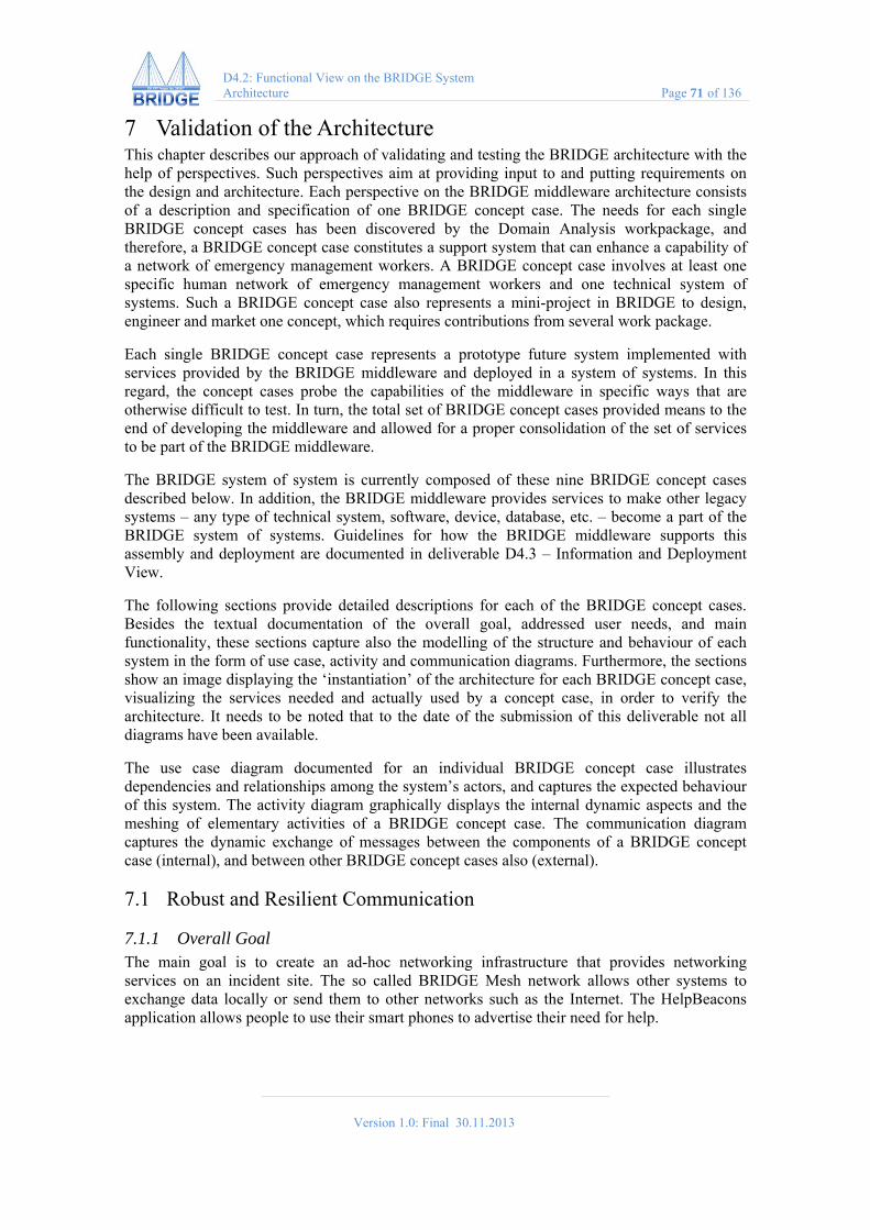
Version 1.0: Final 30.11.2013
D4.2: Functional View on the BRIDGE System Architecture Page 71 of 136
7 Validation of the Architecture This chapter describes our approach of validating and testing the BRIDGE architecture with the help of perspectives. Such perspectives aim at providing input to and putting requirements on the design and architecture. Each perspective on the BRIDGE middleware architecture consists of a description and specification of one BRIDGE concept case. The needs for each single BRIDGE concept cases has been discovered by the Domain Analysis workpackage, and therefore, a BRIDGE concept case constitutes a support system that can enhance a capability of a network of emergency management workers. A BRIDGE concept case involves at least one specific human network of emergency management workers and one technical system of systems. Such a BRIDGE concept case also represents a mini-project in BRIDGE to design, engineer and market one concept, which requires contributions from several work package.
Each single BRIDGE concept case represents a prototype future system implemented with services provided by the BRIDGE middleware and deployed in a system of systems. In this regard, the concept cases probe the capabilities of the middleware in specific ways that are otherwise difficult to test. In turn, the total set of BRIDGE concept cases provided means to the end of developing the middleware and allowed for a proper consolidation of the set of services to be part of the BRIDGE middleware.
The BRIDGE system of system is currently composed of these nine BRIDGE concept cases described below. In addition, the BRIDGE middleware provides services to make other legacy systems – any type of technical system, software, device, database, etc. – become a part of the BRIDGE system of systems. Guidelines for how the BRIDGE middleware supports this assembly and deployment are documented in deliverable D4.3 – Information and Deployment View.
The following sections provide detailed descriptions for each of the BRIDGE concept cases. Besides the textual documentation of the overall goal, addressed user needs, and main functionality, these sections capture also the modelling of the structure and behaviour of each system in the form of use case, activity and communication diagrams. Furthermore, the sections show an image displaying the ‘instantiation’ of the architecture for each BRIDGE concept case, visualizing the services needed and actually used by a concept case, in order to verify the architecture. It needs to be noted that to the date of the submission of this deliverable not all diagrams have been available.
The use case diagram documented for an individual BRIDGE concept case illustrates dependencies and relationships among the system’s actors, and captures the expected behaviour of this system. The activity diagram graphically displays the internal dynamic aspects and the meshing of elementary activities of a BRIDGE concept case. The communication diagram captures the dynamic exchange of messages between the components of a BRIDGE concept case (internal), and between other BRIDGE concept cases also (external).
7.1 Robust and Resilient Communication
7.1.1 Overall Goal The main goal is to create an ad-hoc networking infrastructure that provides networking services on an incident site. The so called BRIDGE Mesh network allows other systems to exchange data locally or send them to other networks such as the Internet. The HelpBeacons application allows people to use their smart phones to advertise their need for help.

Version 1.0: Final 30.11.2013
D4.2: Functional View on the BRIDGE System Architecture Page 72 of 136
7.1.2 Addressed User Needs This concept case addresses the following user needs that have been identified as part of the work undertaken by the Domain Analysis workpackage.
ID Summary BRIDGE-66 Support for identifying misinformation on social media BRIDGE-75 The system provides an interface to consider social media with the goal to
support emergency and crisis management. BRIDGE-80 Declarative accounts of data processing steps and results of complex data
analysis processes such as data mining should be provided to stakeholders
7.1.3 Main Functionality In an emergency situation the first network to become unavailable are cellular networks. Although emergency forces have priority to use this form of communication, the access may still be limited and victims at the emergency area have no possibility to send their help requests. The concept case Robust and Resilient Communication provide the possibility to communicate with devices in an emergency area over different exploitable channels. It comprises several components:
1. Wireless Mesh routers that form an ad-hoc network (called the BRIDGE Mesh) to provide a networking infrastructure for other systems on the scene (e.g., eTriage)
2. The HelpBeacons application that allows people to call for help using an Android smart phone
3. The HelpBeacons Seeker application that is used by first responders to collect SOS messages
The BRIDGE Mesh is an ad-hoc network, which will be based on deployed MESH Bridges, which have multiple network interfaces beside a 802.11s interface. As first responders arrive at the incident site and explore the region they carry the MESH Bridges with them and place them at given distances. The MESH Bridges create an ad-hoc WiFi network, where data is forwarded over multiple hops. Through this deployment the area gains network coverage. This network can from now on be used by different emergency forces, as a shared medium, over which communication or other data can flow. Additionally MESH Bridges accept local networks to attach to them (like ZigBee networks, Bluetooth piconets, etc.). These local systems can from now on be reached over the BRIDGE Mesh and data can be forwarded between them and the Incident Centre.
The BRIDGE Mesh (see Figure 30) can be deployed during a crisis using wireless mesh routers that provide the networking infrastructure. The wireless mesh routers form an ad-hoc networking infrastructure that can be used by other concept cases to exchange data. All routers provide wireless access points to allow other devices (such as smart phones, notebooks or the eTriage bracelets) to join the network. Some routers provide gateways to other networks such as the Internet and bridge different wireless technologies.

Version 1.0: Final 30.11.2013
D4.2: Functional View on the BRIDGE System Architecture Page 73 of 136
Figure 30 – Infrastructure Diagram of the BRIDGE Mesh
The HelpBeacons System provides a way for people to call for help using their Android smart phones. The HelpBeacons system uses the Wi-Fi wireless technology to advertise short help messages. First responders that use a HelpBeacons Seeker application can collect beacons in their vicinity and locate victims.
Technically, the idea is implemented by encoding short messages inside the name of the Wi-Fi access point created by the victim’s smart phone. Any device in range can see these messages using its Wi-Fi interface.
Figure 31 – The HelpBeacons App (left) & Front Officer using the Seeker Device (right)
The HelpBeacons Seeker application has been designed in a way that is does not need any user intervention to collect HelpBeacons and send them to the BRIDGE Mesh. This allows the first responder to fully focus on his/her tasks. Optionally, the first responder can be notified via acoustic signals or vibration when a new HelpBeacon has been found.
Smartphones running the HelpBeacons application may join the BRIDGE Mesh and leave it dynamically and thus, form an opportunistic network infrastructure. One smart phone running

Version 1.0: Final 30.11.2013
D4.2: Functional View on the BRIDGE System Architecture Page 74 of 136
the HelpBeacons Seeker application will collect the help messages and forward them via the BRIDGE Mesh. Collected HelpBeacons are sent by the seeker device to the BRIDGE mesh that provides connection to other BRIDGE systems such as the BRIDGE Master. Thus, the Master can visualize information about HelpBeacons, such as the help message itself or the time the help message was received by the seeker. If the GPS position of the victim and/or the seeker is available, the Master can visualize the location of HelpBeacons on a map.
7.1.4 Integration with Other Concept Cases The information that is collected by the HelpBeacons Seeker application is sent to the BRIDGE Mesh network where a dedicated service first stores the received data locally. The data is then transferred via the BRIDGE middleware to other interested parties. Thus, the BRIDGE Master can access and visualize the help beacons.
7.1.5 Perspective on the BRIDGE Architecture The concept case ‘Robust and Resilient Communication’ makes use of the following services provided by the BRIDGE middleware (see Figure below). Also, use case diagrams, activity diagrams and communication diagrams are provided.
Figure 32 – Robust & Resilient Communication Perspective

Version 1.0: Final 30.11.2013
D4.2: Functional View on the BRIDGE System Architecture Page 75 of 136
Figure 33 – Mesh Use Case Diagram
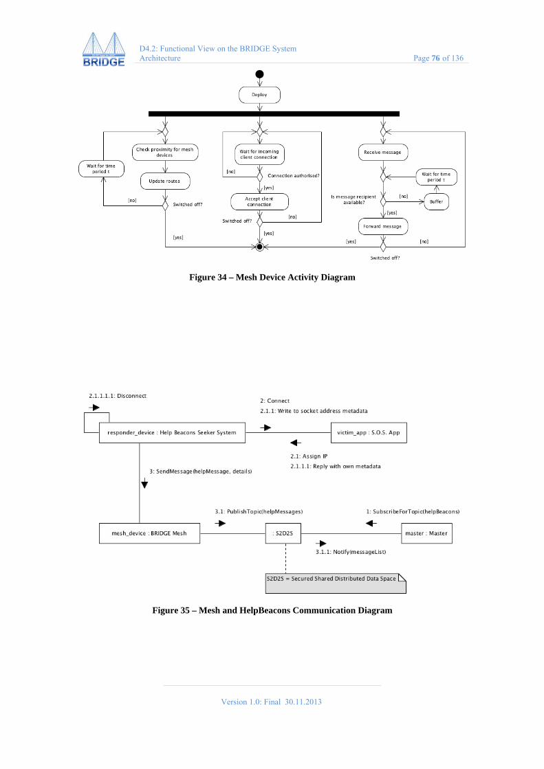
Version 1.0: Final 30.11.2013
D4.2: Functional View on the BRIDGE System Architecture Page 76 of 136
Figure 34 – Mesh Device Activity Diagram
Figure 35 – Mesh and HelpBeacons Communication Diagram
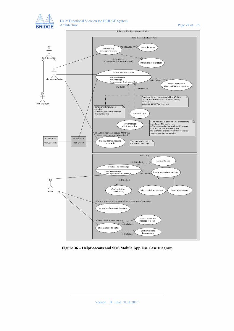
Version 1.0: Final 30.11.2013
D4.2: Functional View on the BRIDGE System Architecture Page 77 of 136
Figure 36 – HelpBeacons and SOS Mobile App Use Case Diagram

Version 1.0: Final 30.11.2013
D4.2: Functional View on the BRIDGE System Architecture Page 78 of 136
Figure 37 – HelpBeacon Activity Diagram

Version 1.0: Final 30.11.2013
D4.2: Functional View on the BRIDGE System Architecture Page 79 of 136
Figure 38 – SOS Mobile App Activity Diagram
Version 1.0: Final 30.11.2013
D4.2: Functional View on the BRIDGE System Architecture Page 80 of 136
7.2 Adaptive Logistics
7.2.1 Overall Goal The BRIDGE concept case Adaptive Logistics characterizes large-scale emergency management operations as Complex Dynamic Multi-Agency Distributed Systems. It explores how the efforts deployed by all the systems’ human participants can be coordinated with artificial components, in such a way that the BRIDGE system of systems as a whole displays coherent, goal-directed behaviour, realizing its goals effective and efficiently.
7.2.2 Addressed User Needs This concept case addresses the following user needs that have been identified as part of the work undertaken by the Domain Analysis workpackage.
ID Summary BRIDGE-56 Accurate dynamic description of resources, patients, evacuees BRIDGE-58 Configuring Awareness and Communication in relation to management of
resources, patients, evacuees
7.2.3 Main Functionality A dynamic multi-agency collaboration is organised using workflows (or more specific: a ‘WorkFlow Generation and Management (WFGM) sub-system’). To organize this collaboration the WFGM sub-system requires system awareness and specific capabilities to plan, instantiate, monitor and adjust activities. The Adaptive Logistics concept case uses an operational workflow to establish collaboration between various BRIDGE system components.
System Awareness The purpose of system awareness information is to make explicit what the capabilities of the emergency management responders and their technical systems are: what roles, causes and effects exist in the operation domain and what does the overall emergency management operation currently tries to achieve.
The component does this by:
Gathering knowledge regarding the capabilities and constraints of participating entities and their own characteristic approaches to resource deployment
Exchanging information regarding plans and intentions Searching for collaboration opportunities Dynamically keeping track of the current goals of the system

Version 1.0: Final 30.11.2013
D4.2: Functional View on the BRIDGE System Architecture Page 81 of 136
Figure 39 – Simple Workflow ‘Victim Evacuation’
Collaborative Planning The Adaptive Logistics concept case explores the deployment of three WFGM mechanisms that collaboratively compute workflows to coordinate the BRIDGE efforts:
COMPASS/SMDS deploys a classic reasoning algorithm, iteratively constructing workflows that achieve a given system goal. From the generated workflows, the best matching the systems’ current requirements is selected. This approach will yield good results for new complex goals that cannot be pre-planned.
CoWS uses templates describing relevant domain information to construct workflows. The templates contain gaps that need to be filled in with other templates or services. This approach will show good results in environments where certain complex tasks occur frequently and can be specified at design time.
ATOM uses an opportunistic approach to planning and execution: based on a survey of the current situation and rough notion of how to achieve a goal, only the first (or, alternatively, next) step(s) are planned and executed. The planning of later steps is delayed, based on the idea that the situation may change. In BRIDGE we will use ATOM to coordinate the deployment of resources.
The WFGM mechanisms interact using the BRIDGE Annotated Workflow Language (BRAWL). The workflow processes used are:
Instantiation: Once a workflow has been selected for execution, the WFGM system needs to configure the resources in the BRIDGE system of systems to execute that workflow.
Monitoring: Monitoring helps ensure the system accomplishes what it actually needs to accomplish and to detect failure to accomplish or deviation from agreed-upon qualities.
Adjustment: In case the monitoring mechanisms detect an (immanent) failure, the WFGM system has a number of options, depending on the nature and severity of the failure: Ignore, Reconfigure, Regenerate, Escalate, Reject.
7.2.4 Integration with other Concept Cases Advanced Logistics establishes collaboration between various BRIDGE system components, including DEIN, Situation aWAre Resource Management (SWARM), the Risk Analyser Modeller and Advanced Situation Awareness - Prediction Modelling.

Version 1.0: Final 30.11.2013
D4.2: Functional View on the BRIDGE System Architecture Page 82 of 136
7.2.5 Perspective on the BRIDGE Architecture The concept case ‘Adaptive Logistics’ makes use of the following services provided by the BRIDGE middleware (see Figure below). Also, use case diagrams, activity diagrams and communication diagrams are provided.
Figure 40 – Adaptive Logistics Perspective

Version 1.0: Final 30.11.2013
D4.2: Functional View on the BRIDGE System Architecture Page 83 of 136
Figure 41 – Adaptive Logistics Use Case Diagram

Version 1.0: Final 30.11.2013
D4.2: Functional View on the BRIDGE System Architecture Page 84 of 136
Figure 42 – Adaptive Logistics Activity Diagram

Version 1.0: Final 30.11.2013
D4.2: Functional View on the BRIDGE System Architecture Page 85 of 136
Figure 43 – Adaptive Logistics Communication Diagram
7.3 Federated Control Room Support
7.3.1 Overall Goal BRIDGE Federated Control Room Support (FCRS) makes it easier for multiple agencies to work together in complex emergency management operations. FCRS can be used to overcome the lack of interoperability between the actual (legacy) systems with which the many organizations at many locations must actually work.
7.3.2 Addressed User Needs This concept case addresses the following user needs that have been identified as part of the work undertaken by the Domain Analysis workpackage.
ID Summary BRIDGE-59 Data Sharing between agencies BRIDGE-61 Legitimate and secure data sharing BRIDGE-73 First responders need to know the location of members of all agencies
7.3.3 Main Functionality BRIDGE FCRS takes a novel approach to the establishment of interoperability in ad-hoc teams across agencies and across borders. By taking a capability-driven approach that does not require joint standards and a common terminology right from the start FCRS makes it possible to achieve:
Emergent standard procedures by evolving cross-agency operating procedures via practical emergence from the actually available capabilities that agencies have to offer.
Emergent standard terminology. Evolve cross-agency understanding of the capabilities to provide information and to conduct work by means of emergence from actual interactions involving the request and provision of services.
BRIDGE FCRS provides support for three basic tasks:
Team formation: The formation of cross-agency and cross-border teams that will work together on specific processes such as air-support for fire fighting, evacuation, search and rescue, or the transportation the wounded to hospitals.

Version 1.0: Final 30.11.2013
D4.2: Functional View on the BRIDGE System Architecture Page 86 of 136
Team process monitoring: FCRS allows teams and commanders to monitor the activities of simple and more complex joint processes, involving multiple agencies, roles, tasks and systems.
Team communication: FCRS allows participants in teams to easily communicate within a team via multiple modes of communication as they become available by means of the infrastructure: chat, messaging, telephone, and videoconference.
The Team Formation Module consists of software that makes it easy for commanders to assemble a team that is completely capable of handling all specific tasks that are required to get the main job done. The key mechanism that makes this possible relies on principles of professional self-organization, where each participant in the team takes responsibility for acquiring all the specific support he or she needs to complete the tasks by means of smartly structured requests and responses.
Figure 44 – Geographical View of Burn Wound Team
The Team Monitoring Module makes it possible for any team member to see what other team members are doing and what progress they are making. This is done by visualizing the flow of the smart requests and responses at different levels of detail. This allows teams to improve or reconfigure themselves when critical services run into difficulties.
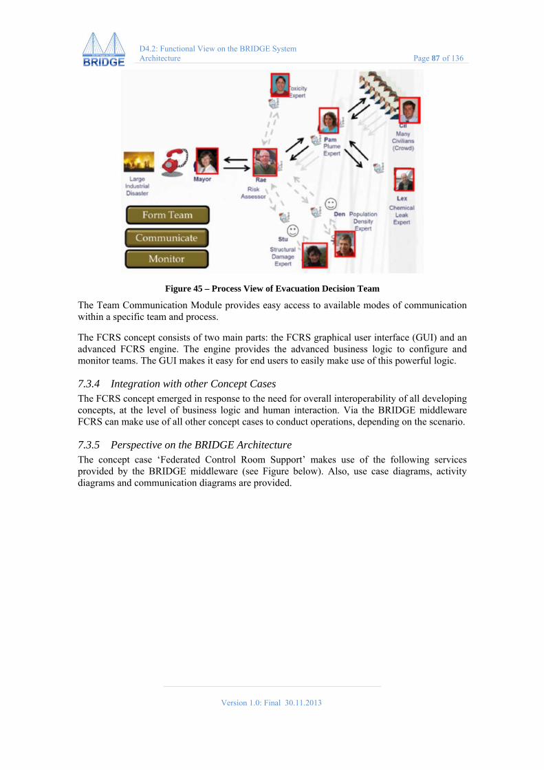
Version 1.0: Final 30.11.2013
D4.2: Functional View on the BRIDGE System Architecture Page 87 of 136
Figure 45 – Process View of Evacuation Decision Team
The Team Communication Module provides easy access to available modes of communication within a specific team and process.
The FCRS concept consists of two main parts: the FCRS graphical user interface (GUI) and an advanced FCRS engine. The engine provides the advanced business logic to configure and monitor teams. The GUI makes it easy for end users to easily make use of this powerful logic.
7.3.4 Integration with other Concept Cases The FCRS concept emerged in response to the need for overall interoperability of all developing concepts, at the level of business logic and human interaction. Via the BRIDGE middleware FCRS can make use of all other concept cases to conduct operations, depending on the scenario.
7.3.5 Perspective on the BRIDGE Architecture The concept case ‘Federated Control Room Support’ makes use of the following services provided by the BRIDGE middleware (see Figure below). Also, use case diagrams, activity diagrams and communication diagrams are provided.

Version 1.0: Final 30.11.2013
D4.2: Functional View on the BRIDGE System Architecture Page 88 of 136
Figure 46 – Federated Control Rooms Support Perspective
7.4 Advanced Situation Awareness
7.4.1 Overall Goal BRIDGE Advanced Situation Awareness (ASA) assists first responders on scene in increasing situational awareness by supplying real-time visual and other information on the extent of the disaster and its consequences.
7.4.2 Addressed User Needs This concept case addresses the following user needs that have been identified as part of the work undertaken by the Domain Analysis workpackage.
ID Summary BRIDGE-98 The first responders operating in the field should have an improved awareness
of any risks and dangers at the incident site.
7.4.3 Main Functionality The main functionality of the Advanced Situation Awareness concept case is to provide support for risk analysis and decision making during emergency and crisis situations where the decision time frame is longer than a few minutes. It consists of the following three components: Hexacopter, Expert System, and Modelling Module.
Hexacopter The Hexacopter is an unmanned aerial vehicle (UAV) system, which comprises
Flying platform with six motors; Global Positioning System (GPS) and radar;

Version 1.0: Final 30.11.2013
D4.2: Functional View on the BRIDGE System Architecture Page 89 of 136
Video and infrared cameras; On-board computer; Environmental sensors; and Ground control station.
The Hexacopter provides a live video from a bird’s-eye-view perspective, a parallel infrared video, and real-time environmental sampling data, which help assess the magnitude of destruction, fires and health hazards to first responders and affected population. The UAV can be controlled manually or put into a pre-programmed automatic flight modus.
Figure 47 – Unmanned Aerial Vehicle
Figure 48 – Ground Control Station
Expert System The Expert System is a software, used to automatically analyse the incoming environmental measurements data supplied by the Hexacopter to the Ground Station. The data is compared against national and international standards, and combined with expert recommendations. The aim of the Expert System is to help the incident commander interpret the obtained environmental data and ease the decision-making in a complex emergency.
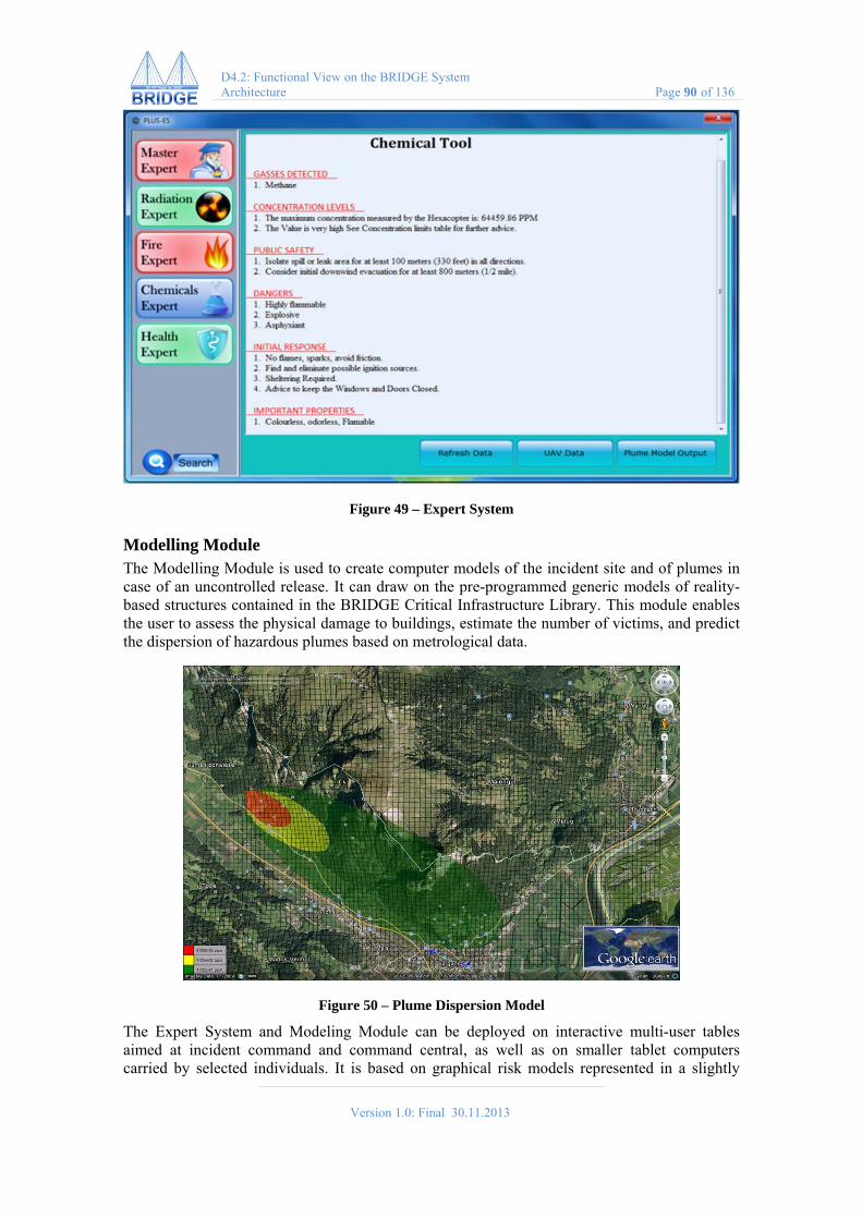
Version 1.0: Final 30.11.2013
D4.2: Functional View on the BRIDGE System Architecture Page 90 of 136
Figure 49 – Expert System
Modelling Module The Modelling Module is used to create computer models of the incident site and of plumes in case of an uncontrolled release. It can draw on the pre-programmed generic models of reality-based structures contained in the BRIDGE Critical Infrastructure Library. This module enables the user to assess the physical damage to buildings, estimate the number of victims, and predict the dispersion of hazardous plumes based on metrological data.
Figure 50 – Plume Dispersion Model
The Expert System and Modeling Module can be deployed on interactive multi-user tables aimed at incident command and command central, as well as on smaller tablet computers carried by selected individuals. It is based on graphical risk models represented in a slightly

Version 1.0: Final 30.11.2013
D4.2: Functional View on the BRIDGE System Architecture Page 91 of 136
simplified version of the CORAS risk modeling language4. For foreseen types of emergency scenarios, a library of predefined risk models will provide starting points for the analysis, to be filled in and tailored to the specific scenario when it occurs.
7.4.4 Integration with Other Concept Cases The different components of BRIDGE ASA assist in providing an accurate, real-time update on the incident, strengthening the capabilities of BRIDGE Master and BRIDGE SWARM concept cases.
7.4.5 Perspective on the BRIDGE Architecture The concept case ‘Advanced Situation Awareness’ makes use of the following services provided by the BRIDGE middleware (see Figure below). Also, use case diagrams, activity diagrams and communication diagrams are provided.
Figure 51 – Advanced Situation Awareness Perspective
4 Mass Soldal Lund, Bjørnar Solhaug and Ketil Stølen: Model-Driven Risk Analysis. The CORAS Approach. Springer, 2011.
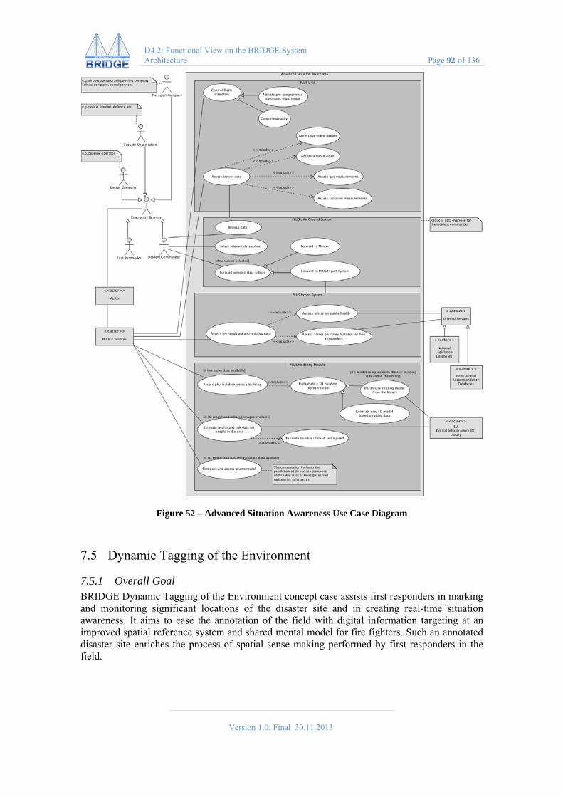
Version 1.0: Final 30.11.2013
D4.2: Functional View on the BRIDGE System Architecture Page 92 of 136
Figure 52 – Advanced Situation Awareness Use Case Diagram
7.5 Dynamic Tagging of the Environment
7.5.1 Overall Goal BRIDGE Dynamic Tagging of the Environment concept case assists first responders in marking and monitoring significant locations of the disaster site and in creating real-time situation awareness. It aims to ease the annotation of the field with digital information targeting at an improved spatial reference system and shared mental model for fire fighters. Such an annotated disaster site enriches the process of spatial sense making performed by first responders in the field.

Version 1.0: Final 30.11.2013
D4.2: Functional View on the BRIDGE System Architecture Page 93 of 136
7.5.2 Addressed User Needs This concept case addresses the following user needs that have been identified as part of the work undertaken by the Domain Analysis workpackage.
ID Summary BRIDGE-90 The triage tags should be easy to identify, in all weather and lighting
conditions BRIDGE-92 The triage tags should not be easily exchangeable by victims themselves BRIDGE-95 Any exchange of triage tags should be detectable.
7.5.3 Main Functionality The Dynamic Tagging of the Environment concept case provides functionality to place several types of real and virtual tags in the environment, and also to discover and explore marked and tagged environment. Such a tagging process is as follows:
1. In their exploration process of the incident site, first responders mark specific points in space either
a. physically through the deployment of a sensor tag or b. virtually through some type of digital information such as a specific symbol, a
voice recording, a text, etc. 2. The Master receives the sensor values or the digital information associated with a GPS
position and visualizes them on the map. 3. Other first responder teams in the field use a mobile device with a map view or an
augmented reality view to discover the information deposited by the former first responder team in the field.
Figure 53 – Tagging the Environment using Symbolic Icons
The Tagging Device The Tagging Device (see Figure 53) forms the main point of access for the dynamic tagging system and serves two purposes: First, the creation and deployment of dynamic tags in the form of digital information, and second, the exploration of already deployed dynamic tags.
The Tagging Device already offers a range of pre-built icons that the user can possibly exploit as tags. Each icon visually represents one possible situation that the user might like to report back to his team members and the command post through the dynamic tagging system. If the user selects one of these icons, the dynamic tagging system associates the current position to the respective icon and stores it in the database. At the same time this icon appears on the map of

Version 1.0: Final 30.11.2013
D4.2: Functional View on the BRIDGE System Architecture Page 94 of 136
the Master. In a second optional step, the user might also want to bind a personal note with the selected and positioned icon. Such a personal note can consist in a voice recording, an image, written text or a drawing.
Visualizing Tags in the Environment The Tagging Device is also to visualize the dynamic tags placed in the environment. Two different visualization modes are available: The map mode (Figure 2) and the augmented reality mode (Figure 3). In the map mode, icons representing each dynamic tag are displayed on a map. For outdoors, a Google Map is used and the user’s position is acquired by GPS. For indoors, the model of the building and roughly estimated positions are used.
The augmented reality mode presents the stream of the built-in camera with an overlay of abovementioned icons representing a dynamic tag. The user operates the Tagging Device as a ‘lens’, scanning the environment by turning around and acquiring the digital information associated with a dynamic tag in his current view. Touching on one of the icons with the finger in either visualization mode, the user receives the digital information, either sensor data or human-made information (e.g. voice recording), on the screen or through the loudspeakers of the tagging device.
Figure 54 – Looking ‘through’ the Tagging Device using Augmented Reality Mode
Figure 55 – Using the Tagging Device as a Map Viewer Showing important Tagged Places
Sensor Tags Sensor tags continuously measure environmental parameters such as air temperature, CO2 contamination, etc. (see Figure 4). First responders can deploy these tags in the environment through clipping them to the relevant location or through throwing them towards a desired direction. Once activated, the tags acquire the exact GPS position and start to send a stream of sensor values to the command post.
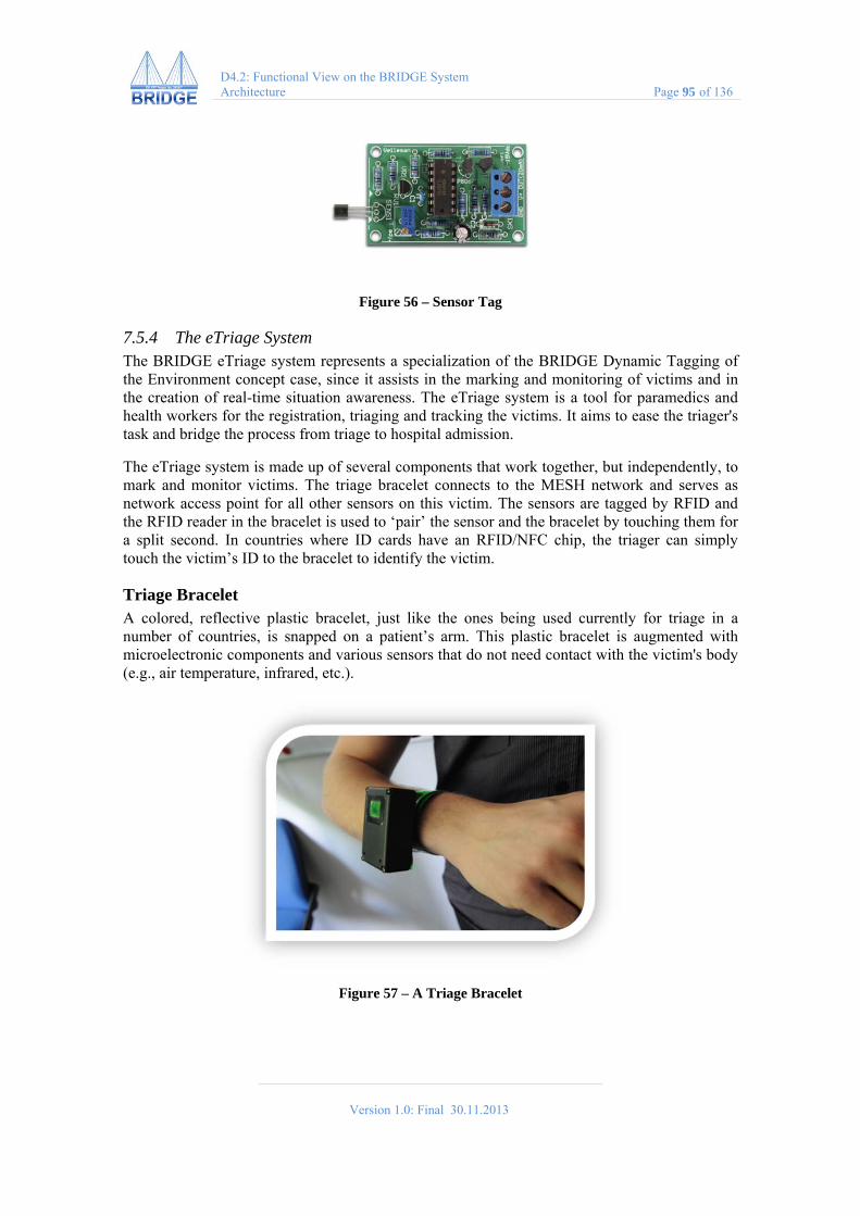
Version 1.0: Final 30.11.2013
D4.2: Functional View on the BRIDGE System Architecture Page 95 of 136
Figure 56 – Sensor Tag
7.5.4 The eTriage System The BRIDGE eTriage system represents a specialization of the BRIDGE Dynamic Tagging of the Environment concept case, since it assists in the marking and monitoring of victims and in the creation of real-time situation awareness. The eTriage system is a tool for paramedics and health workers for the registration, triaging and tracking the victims. It aims to ease the triager's task and bridge the process from triage to hospital admission.
The eTriage system is made up of several components that work together, but independently, to mark and monitor victims. The triage bracelet connects to the MESH network and serves as network access point for all other sensors on this victim. The sensors are tagged by RFID and the RFID reader in the bracelet is used to ‘pair’ the sensor and the bracelet by touching them for a split second. In countries where ID cards have an RFID/NFC chip, the triager can simply touch the victim’s ID to the bracelet to identify the victim.
Triage Bracelet A colored, reflective plastic bracelet, just like the ones being used currently for triage in a number of countries, is snapped on a patient’s arm. This plastic bracelet is augmented with microelectronic components and various sensors that do not need contact with the victim's body (e.g., air temperature, infrared, etc.).
Figure 57 – A Triage Bracelet

Version 1.0: Final 30.11.2013
D4.2: Functional View on the BRIDGE System Architecture Page 96 of 136
Triage Relay The Triage Beacon is a small device that is intended to clip on a normal trouser belt like a beeper. It needs no interaction from the triager; its role is to gather data from the disaster field and transmit them to the command center in case the BRIDGE Mesh has a problem.
Clip-On Sensors Clip-on sensors are those that need contact with the victim's body, e.g., heart rate, breathing rate, blood pressure, etc. They allow monitoring the victim instead of simply marking him or her. The sensors are intended to be used either by the triagers or by the medical personnel at the assembly point, as needed.
Triage Tablet The main purpose of the triage tablet is to visualize the triage data. It is intended to be used by either triagers, or by the medical personnel at the gathering place. Two different visualization modes are available: The map mode (figure left) and the augmented reality mode (figure right). In the map mode, icons representing each patient are displayed on a map. Each icon contains the most important triage data category, pulse and respiration rate. For outdoors, a Google Map is used and the users own plus patient’s positions are acquired by GPS. For indoors, floor plans and roughly estimated positions are used.
The augmented reality mode presents a camera stream on which again category, pulse and respiration rate are overlayed as icons. The medic uses the tablet as ‘lens’, scanning the environment by turning and acquiring triage data about his current view.
Figure 58 – The Triage Tablet in Two Modes
In both modes, a click on an icon reveals all data about a patient. As alternative, the triage tablet comprehends an RFID reader which allows for scanning a patient’s bracelet in order to call up the detailed patient information on the screen. The triage tablet can, additionally, function just like a triage relay.
7.5.5 Integration with Other Concept Cases The Dynamic Tagging of the Environment concept case provides information about the environment (tags) and vital information from triaged victims bound to position information to the BRIDGE Master. It uses the BRIDGE Mesh to get the data through to the Master Table.

Version 1.0: Final 30.11.2013
D4.2: Functional View on the BRIDGE System Architecture Page 97 of 136
7.5.6 Perspective on the BRIDGE Architecture The concept case ‘Dynamic Tagging of the Environment’ makes use of the following services provided by the BRIDGE middleware (see Figure below). Also, use case diagrams, activity diagrams and communication diagrams are provided.
Figure 59 – Dynamic Tagging of the Environment Perspective

Version 1.0: Final 30.11.2013
D4.2: Functional View on the BRIDGE System Architecture Page 98 of 136
Figure 60 – Dynamic Tagging of the Environment and eTriage Use Case Diagram

Version 1.0: Final 30.11.2013
D4.2: Functional View on the BRIDGE System Architecture Page 99 of 136
Figure 61 – Dynamic Tagging of the Environment and eTriage Activity Diagram
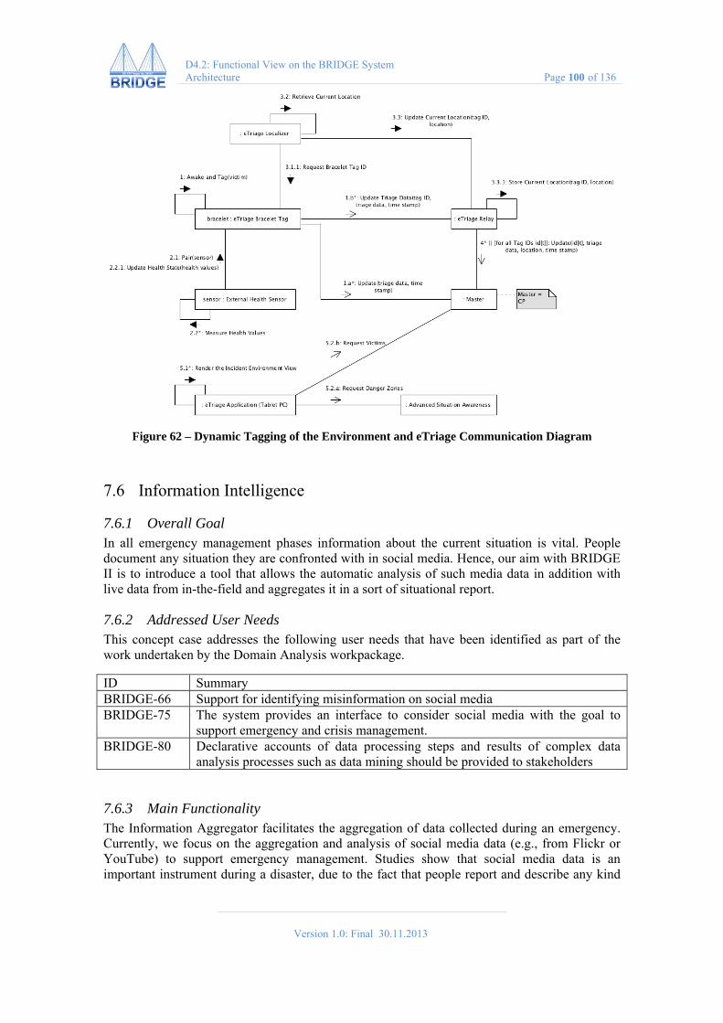
Version 1.0: Final 30.11.2013
D4.2: Functional View on the BRIDGE System Architecture Page 100 of 136
Figure 62 – Dynamic Tagging of the Environment and eTriage Communication Diagram
7.6 Information Intelligence
7.6.1 Overall Goal In all emergency management phases information about the current situation is vital. People document any situation they are confronted with in social media. Hence, our aim with BRIDGE II is to introduce a tool that allows the automatic analysis of such media data in addition with live data from in-the-field and aggregates it in a sort of situational report.
7.6.2 Addressed User Needs This concept case addresses the following user needs that have been identified as part of the work undertaken by the Domain Analysis workpackage.
ID Summary BRIDGE-66 Support for identifying misinformation on social media BRIDGE-75 The system provides an interface to consider social media with the goal to
support emergency and crisis management. BRIDGE-80 Declarative accounts of data processing steps and results of complex data
analysis processes such as data mining should be provided to stakeholders
7.6.3 Main Functionality The Information Aggregator facilitates the aggregation of data collected during an emergency. Currently, we focus on the aggregation and analysis of social media data (e.g., from Flickr or YouTube) to support emergency management. Studies show that social media data is an important instrument during a disaster, due to the fact that people report and describe any kind

Version 1.0: Final 30.11.2013
D4.2: Functional View on the BRIDGE System Architecture Page 101 of 136
of situation they are involved in. Hence, the increasing usage of social media platforms delivers valuable insight into crisis-related issues. The BRIDGE Information Intelligence comprises several components:
Aggregation Component: It performs the aggregation based on sub-events (= specific hotspots of a crisis) and shows the results to the user (see figures below).
Data Simulation Component: It allows the simulation of data during a running exercise. This tool can also be used for training purpose.
Data Collection Component: It is implemented as an Android-App and allows the collection of live data (from within the field).
Figure 63 – Aggregation Component Graphical User Interface
The Aggregation Component performs the aggregation based on online clustering algorithms. It aggregates the data based on their textual and location content. The aggregation can be performed on social media data (e.g., Twitter) and on live data coming from within the field.
The results are shown to the user via a web-based implementation reachable from any browser (e.g., Mozilla, Google Chrome etc.). The GUI contains a map-representation and a detail view for sub-events (see figures below). In addition, it allows filtering the results based on geo-location and/or keywords.
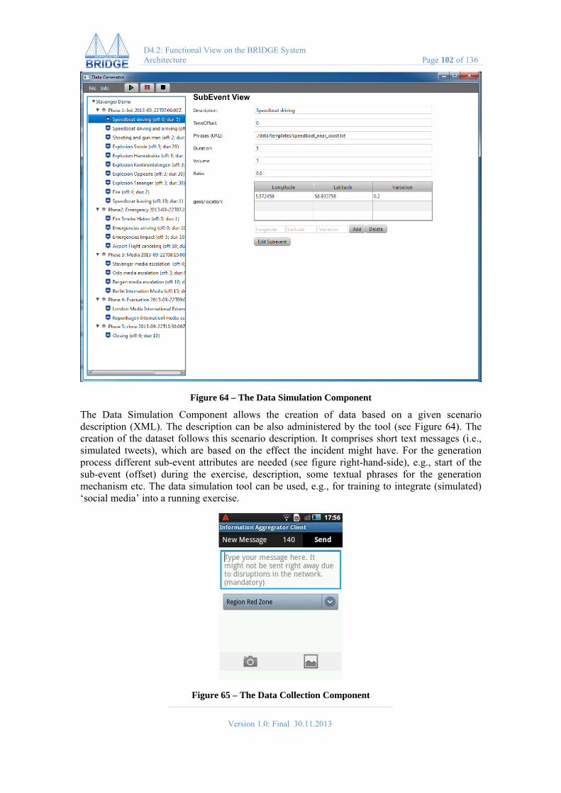
Version 1.0: Final 30.11.2013
D4.2: Functional View on the BRIDGE System Architecture Page 102 of 136
Figure 64 – The Data Simulation Component
The Data Simulation Component allows the creation of data based on a given scenario description (XML). The description can be also administered by the tool (see Figure 64). The creation of the dataset follows this scenario description. It comprises short text messages (i.e., simulated tweets), which are based on the effect the incident might have. For the generation process different sub-event attributes are needed (see figure right-hand-side), e.g., start of the sub-event (offset) during the exercise, description, some textual phrases for the generation mechanism etc. The data simulation tool can be used, e.g., for training to integrate (simulated) ‘social media’ into a running exercise.
Figure 65 – The Data Collection Component

Version 1.0: Final 30.11.2013
D4.2: Functional View on the BRIDGE System Architecture Page 103 of 136
The Data Collection Component allows the introduction of live data into the aggregation process. The Smartphone App bases on the concept case ‘Local Cloud’ which was presented at the first BRIDGE review in Flum. It allows directly the integration of text messages and pictures from persons in the field into the aggregation mechanism. The idea is to enrich the aggregation process with this live data.
7.6.4 Integration with Other Concept Cases The information aggregated by Information Intelligence concept case is passed to the Master Table. This is performed by selecting a specific sub-event which is of importance for the emergency agencies. In addition, it makes use of the general ideas and implementation of the former ‘Local Cloud’ concept case.
7.6.5 Perspective on the BRIDGE Architecture The concept case ‘Information Intelligence’ makes use of the following services provided by the BRIDGE middleware (see Figure below). Also, use case diagrams, activity diagrams and communication diagrams are provided.
Figure 66 – Information Intelligence Perspective

Version 1.0: Final 30.11.2013
D4.2: Functional View on the BRIDGE System Architecture Page 104 of 136
Figure 67 – Information Intelligence Use Case Diagram

Version 1.0: Final 30.11.2013
D4.2: Functional View on the BRIDGE System Architecture Page 105 of 136
Figure 68 – Information Intelligence Activity Diagram
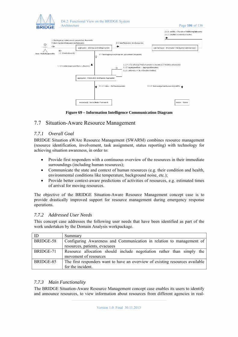
Version 1.0: Final 30.11.2013
D4.2: Functional View on the BRIDGE System Architecture Page 106 of 136
Figure 69 – Information Intelligence Communication Diagram
7.7 Situation-Aware Resource Management
7.7.1 Overall Goal BRIDGE Situation aWAre Resource Management (SWARM) combines resource management (resource identification, involvement, task assignment, status reporting) with technology for achieving situation awareness, in order to:
Provide first responders with a continuous overview of the resources in their immediate surroundings (including human resources);
Communicate the state and context of human resources (e.g. their condition and health, environmental conditions like temperature, background noise, etc.);
Provide better context-aware predictions of activities of resources, e.g. estimated times of arrival for moving resources.
The objective of the BRIDGE Situation-Aware Resource Management concept case is to provide drastically improved support for resource management during emergency response operations.
7.7.2 Addressed User Needs This concept case addresses the following user needs that have been identified as part of the work undertaken by the Domain Analysis workpackage.
ID Summary BRIDGE-58 Configuring Awareness and Communication in relation to management of
resources, patients, evacuees BRIDGE-71 Resource allocation should include negotiation rather than simply the
movement of resources BRIDGE-85 The first responders want to have an overview of existing resources available
for the incident.
7.7.3 Main Functionality The BRIDGE Situation-Aware Resource Management concept case enables its users to identify and announce resources, to view information about resources from different agencies in real-
Version 1.0: Final 30.11.2013
D4.2: Functional View on the BRIDGE System Architecture Page 107 of 136
time, and to allocate resources to specific tasks and locations. It is an agent-based distributed system running on mobile devices (smartphones, laptops, tablets, MDTs) in combination with cloud-based services. Via these latter services, a tight integration with the Master concept is to be expected: resources and their statuses will be visible as clickable icons on an interactive map. Also, the assignment of resources to tasks and usage of the related decision support system can be done directly from the interactive map.
Various different communication media and protocols can be used by the BRIDGE Situation-Aware Resource Management concept case in order to provide a robust and fully functional application even in circumstances with limited connectivity.
The main smartphone functionalities are:
Get insight into: o Location of the incident; o Location of command/control posts; o Location and status of surrounding resources; o Location, assigner and status of my current task.
Inform others about: o First responder task status; o First responder personal status.
Direct (emergency) voice contact with: o (Assistant) Incident Commander; o Any other person (configurable).
The main functionalities provided on the BRIDGE Master System are:
Get insight into: o Location and status of resources; o ETA for moving resources; o Current tasks and their status.
Inform others about: o New task assignments; o Dynamic team formation.
7.7.4 Integration with Other Concept Cases The SWARM concept case integrates the Master Table with a general purpose smartphone application through a secure publish/subscribe service provided by the BRIDGE Middleware. In addition, the SWARM concept case is able to make use of the BRIDGE Mesh for the communication between end-user devices and with the cloud services, but it is also be able to exploit HTTP connections over Wifi/GPRS/UMTS, if available
7.7.5 Perspective on the BRIDGE Architecture The concept case ‘Situation-Aware Resource Management’ makes use of the following services provided by the BRIDGE middleware (see Figure below). Also, use case diagrams, activity diagrams and communication diagrams are provided.

Version 1.0: Final 30.11.2013
D4.2: Functional View on the BRIDGE System Architecture Page 108 of 136
Figure 70 – Situation-Aware Resource Management Perspective
7.8 Master System
7.8.1 Overall Goal The BRIDGE Master System concept case assists the command post in keeping a common operational picture among central actors during a major incident.
7.8.2 Addressed User Needs This concept case addresses the following user needs that have been identified as part of the work undertaken by the Domain Analysis workpackage.
ID Summary BRIDGE-85 The first responders want to have an overview of existing resources available
for the incident. BRIDGE-96 The first responders should always be in control of how much and which type
of information they convey to the BRIDGE system. BRIDGE-67 The emergency personal needs to have an overview of the victims' location
and vital state.
7.8.3 Main Functionality The Master provides functionality to present and act on three types of information, which are accessible through the BRIDGE system of systems:
Information about the incident, e.g., incident location and number and triage status of victims, incident information added by incident response teams
Information about the response, e.g., number and position of police, fire and health vehicles
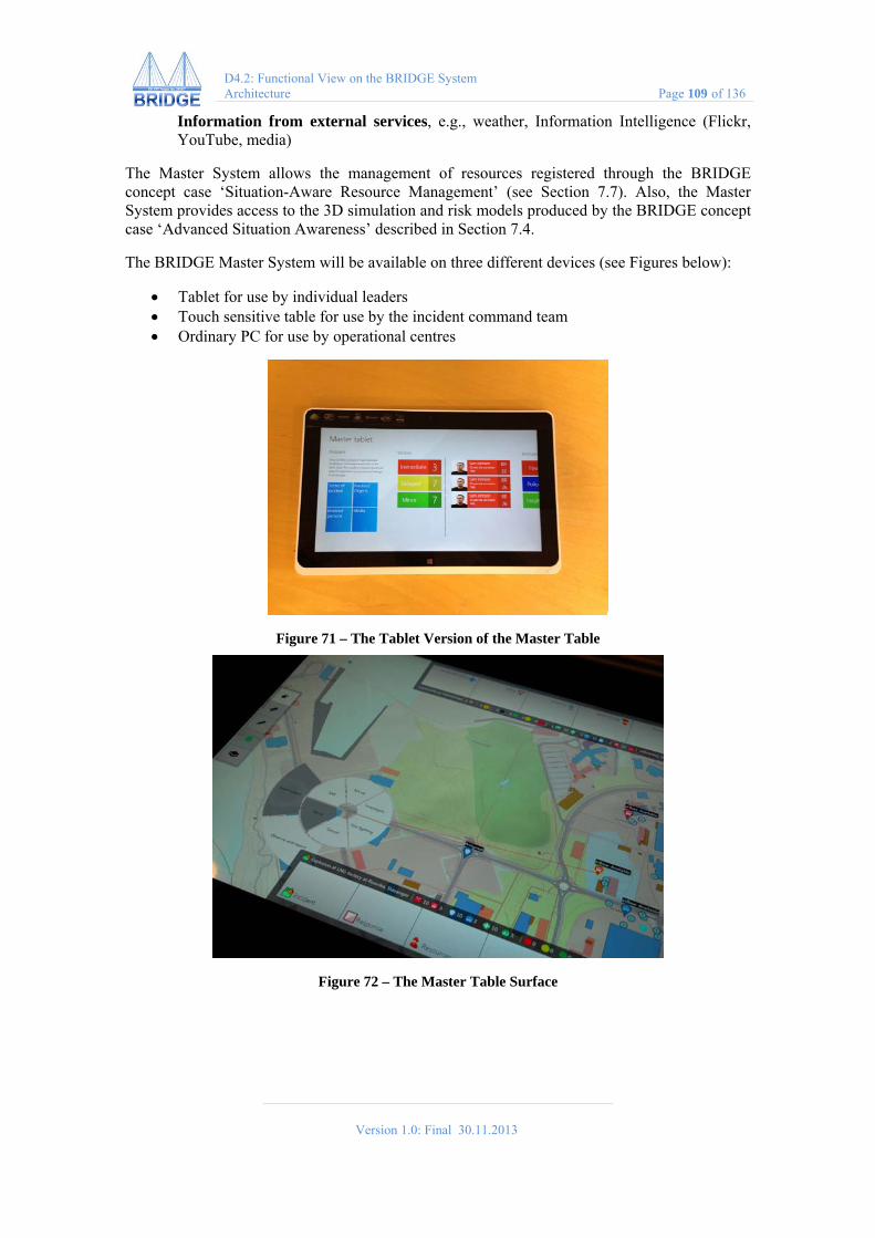
Version 1.0: Final 30.11.2013
D4.2: Functional View on the BRIDGE System Architecture Page 109 of 136
Information from external services, e.g., weather, Information Intelligence (Flickr, YouTube, media)
The Master System allows the management of resources registered through the BRIDGE concept case ‘Situation-Aware Resource Management’ (see Section 7.7). Also, the Master System provides access to the 3D simulation and risk models produced by the BRIDGE concept case ‘Advanced Situation Awareness’ described in Section 7.4.
The BRIDGE Master System will be available on three different devices (see Figures below):
Tablet for use by individual leaders Touch sensitive table for use by the incident command team Ordinary PC for use by operational centres
Figure 71 – The Tablet Version of the Master Table
Figure 72 – The Master Table Surface

Version 1.0: Final 30.11.2013
D4.2: Functional View on the BRIDGE System Architecture Page 110 of 136
Figure 73 – The Large Screen Version of the Master Table
7.8.4 Integration with Other Concept Cases The BRIDGE Master System integrates with almost all other concept cases, because it constitutes the information sink of the BRIDGE system of systems. It provides information visualisation and allows for an effortless exploration of this information.
7.8.5 Perspective on the BRIDGE Architecture The concept case ‘Master System’ makes use of the following services provided by the BRIDGE middleware (see Figure below). Also, use case diagrams, activity diagrams and communication diagrams are provided.
Figure 74 – Master System Perspective
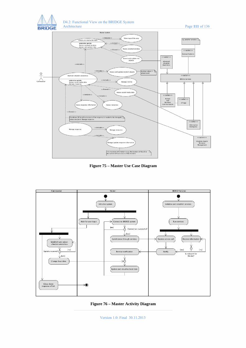
Version 1.0: Final 30.11.2013
D4.2: Functional View on the BRIDGE System Architecture Page 111 of 136
Figure 75 – Master Use Case Diagram
Figure 76 – Master Activity Diagram

Version 1.0: Final 30.11.2013
D4.2: Functional View on the BRIDGE System Architecture Page 112 of 136
Figure 77 – Master Communication Diagram
7.9 First Responder Integrated Training System
7.9.1 Overall Goal The main objective for the concept case BRIDGE First Responder Integrated Training System (FRITS) is to establish an optimal learning and training methodology, supported by an integrated portfolio of sub-systems that will improve the quality of emergency response and crisis management in intra-agency and inter-agency operations.
7.9.2 Addressed User Needs This concept case addresses the following user needs that have been identified as part of the work undertaken by the Domain Analysis workpackage.
ID Summary BRIDGE-76 Any acquired data should be logged for later study or legal purposes. BRIDGE-226 Training systems should be able to simulate patient statistics (pulse, BP etc) in
order to create realistic opportunities for collaboration during multi-agency exercises.
BRIDGE-216 Those participating in training exercises will be exposed to risks (for eg fire or fumes). Training systems should make those participants aware of expected, developing and changes in their risk exposure.
7.9.3 Main Functionality FRITS will use BRIDGE developed methods and tools together with COTS (commercial-of-the-shelf) technology to ensure flexibility and to provide scalability for different end-user needs. The concept is divided into modules, focusing on training, exercises and proper evaluation for improvements:
Training methodology tools Evaluation tools Simulated training; live, virtual and constructive systems (COTS-technology)
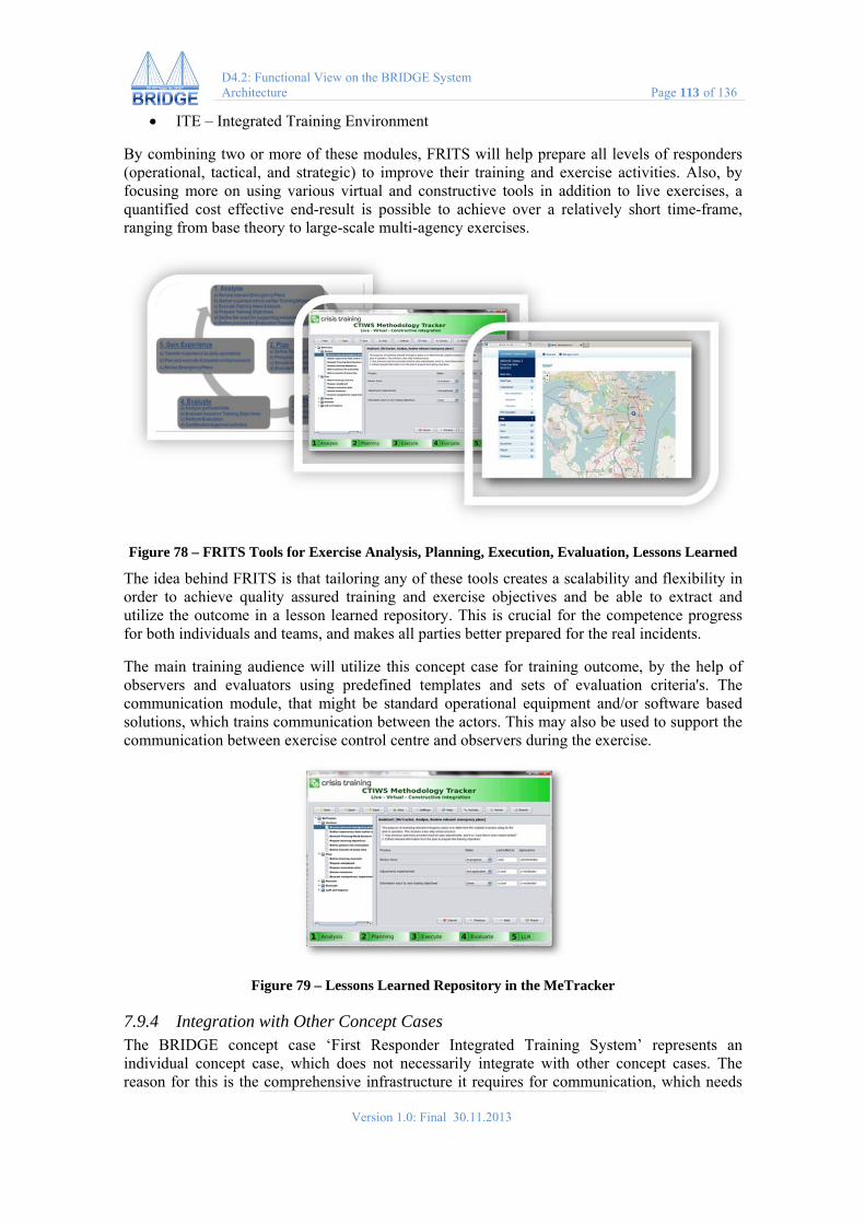
Version 1.0: Final 30.11.2013
D4.2: Functional View on the BRIDGE System Architecture Page 113 of 136
ITE – Integrated Training Environment
By combining two or more of these modules, FRITS will help prepare all levels of responders (operational, tactical, and strategic) to improve their training and exercise activities. Also, by focusing more on using various virtual and constructive tools in addition to live exercises, a quantified cost effective end-result is possible to achieve over a relatively short time-frame, ranging from base theory to large-scale multi-agency exercises.
Figure 78 – FRITS Tools for Exercise Analysis, Planning, Execution, Evaluation, Lessons Learned
The idea behind FRITS is that tailoring any of these tools creates a scalability and flexibility in order to achieve quality assured training and exercise objectives and be able to extract and utilize the outcome in a lesson learned repository. This is crucial for the competence progress for both individuals and teams, and makes all parties better prepared for the real incidents.
The main training audience will utilize this concept case for training outcome, by the help of observers and evaluators using predefined templates and sets of evaluation criteria's. The communication module, that might be standard operational equipment and/or software based solutions, which trains communication between the actors. This may also be used to support the communication between exercise control centre and observers during the exercise.
Figure 79 – Lessons Learned Repository in the MeTracker
7.9.4 Integration with Other Concept Cases The BRIDGE concept case ‘First Responder Integrated Training System’ represents an individual concept case, which does not necessarily integrate with other concept cases. The reason for this is the comprehensive infrastructure it requires for communication, which needs

Version 1.0: Final 30.11.2013
D4.2: Functional View on the BRIDGE System Architecture Page 114 of 136
to be de-coupled from the remaining communication infrastructure used by the other concept cases. However, a common baseline integration driver for use in WISE is available for BRIDGE FRITS connectivity to other applications (both BRIDGE-specific and common protocols), if applicable. A typical setup here is integrating the MasterTable with FRITS.
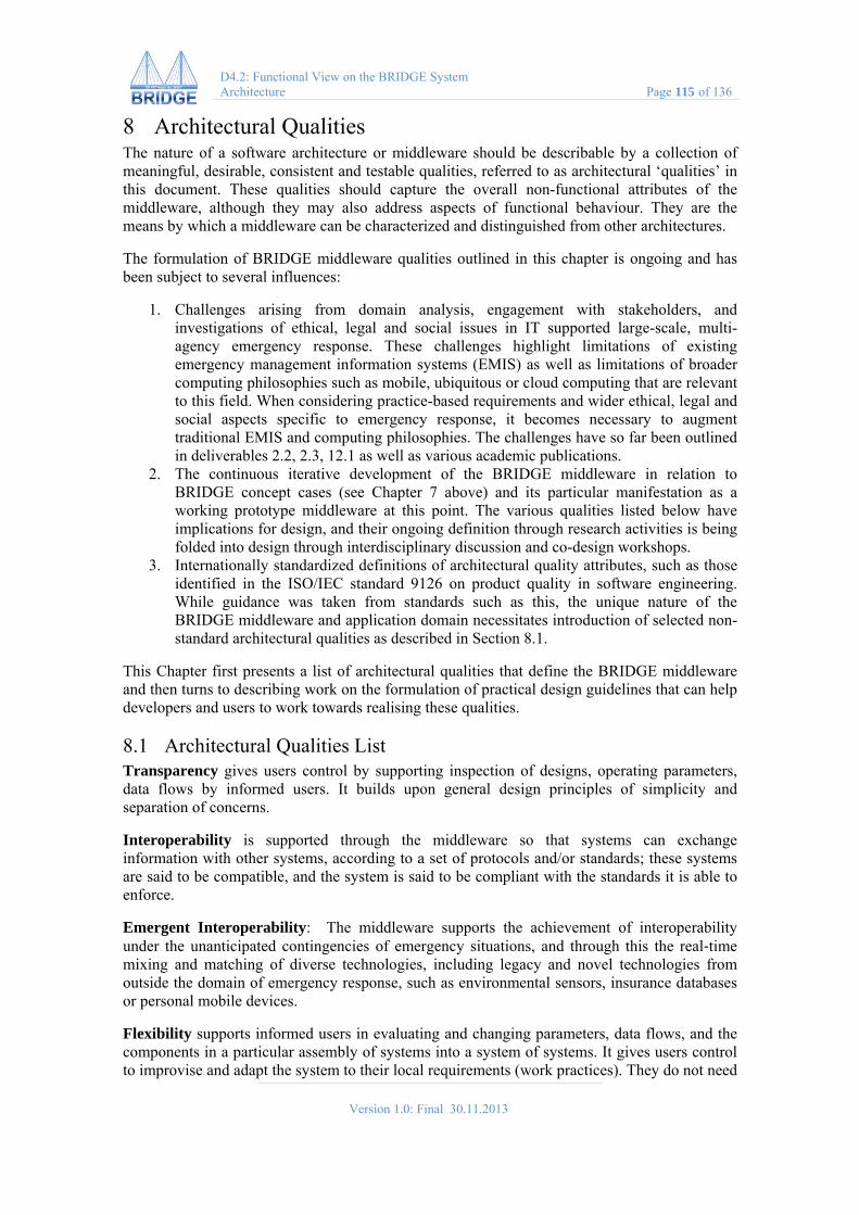
Version 1.0: Final 30.11.2013
D4.2: Functional View on the BRIDGE System Architecture Page 115 of 136
8 Architectural Qualities The nature of a software architecture or middleware should be describable by a collection of meaningful, desirable, consistent and testable qualities, referred to as architectural ‘qualities’ in this document. These qualities should capture the overall non-functional attributes of the middleware, although they may also address aspects of functional behaviour. They are the means by which a middleware can be characterized and distinguished from other architectures.
The formulation of BRIDGE middleware qualities outlined in this chapter is ongoing and has been subject to several influences:
1. Challenges arising from domain analysis, engagement with stakeholders, and investigations of ethical, legal and social issues in IT supported large-scale, multi-agency emergency response. These challenges highlight limitations of existing emergency management information systems (EMIS) as well as limitations of broader computing philosophies such as mobile, ubiquitous or cloud computing that are relevant to this field. When considering practice-based requirements and wider ethical, legal and social aspects specific to emergency response, it becomes necessary to augment traditional EMIS and computing philosophies. The challenges have so far been outlined in deliverables 2.2, 2.3, 12.1 as well as various academic publications.
2. The continuous iterative development of the BRIDGE middleware in relation to BRIDGE concept cases (see Chapter 7 above) and its particular manifestation as a working prototype middleware at this point. The various qualities listed below have implications for design, and their ongoing definition through research activities is being folded into design through interdisciplinary discussion and co-design workshops.
3. Internationally standardized definitions of architectural quality attributes, such as those identified in the ISO/IEC standard 9126 on product quality in software engineering. While guidance was taken from standards such as this, the unique nature of the BRIDGE middleware and application domain necessitates introduction of selected non-standard architectural qualities as described in Section 8.1.
This Chapter first presents a list of architectural qualities that define the BRIDGE middleware and then turns to describing work on the formulation of practical design guidelines that can help developers and users to work towards realising these qualities.
8.1 Architectural Qualities List Transparency gives users control by supporting inspection of designs, operating parameters, data flows by informed users. It builds upon general design principles of simplicity and separation of concerns.
Interoperability is supported through the middleware so that systems can exchange information with other systems, according to a set of protocols and/or standards; these systems are said to be compatible, and the system is said to be compliant with the standards it is able to enforce.
Emergent Interoperability: The middleware supports the achievement of interoperability under the unanticipated contingencies of emergency situations, and through this the real‐time mixing and matching of diverse technologies, including legacy and novel technologies from outside the domain of emergency response, such as environmental sensors, insurance databases or personal mobile devices.
Flexibility supports informed users in evaluating and changing parameters, data flows, and the components in a particular assembly of systems into a system of systems. It gives users control to improvise and adapt the system to their local requirements (work practices). They do not need

Version 1.0: Final 30.11.2013
D4.2: Functional View on the BRIDGE System Architecture Page 116 of 136
to adopt the whole (or the implicit logic) in order to get the benefits afforded by individual systems.
Responsibility BRIDGE system supports users in making themselves aware of technical, legal or regulatory regimes, plans and social/ethical constrains that may affect operations, for example around data protection. At the same time, while imposing standard structures and procedures, systems must, insofar as possible, allow flexibility and deviation in their application.
Formal decision support makes users aware of technical, legal or regulatory regimes, plans and social/ethical constrains that may affect operations. Highlights and explains, insofar as possible, consequences of deviation from default settings.
Privacy supports definition and adherence to privacy preserving policies, rules, techniques as well as exceptions to ensure that information can be collected, shared and used in appropriate ways.
Privacy by design reflects and vindicates privacy preserving policies, rules, and techniques and ensures that information can be collected, shared and used in appropriate ways, depending on the context and situation.
Security offers the ability to be confident that privacy and data protection policies are respected by providing secure data storage and flows based on informed consent or appropriate exceptions.
Traceability allows for all transactions (addition, amendments, deletions, etc.) to be traced to individual actors (human or non-human).
Mixed Intelligence and collaboration: A commitment to support collaborative human sense-making that leverages computational support. All response technology should actively nurture cooperation, collaboration and partnership formation.
Coherence: Bridging diversity of organisational structures, processes and practices, of communication channels, tools, networks to enable collaboration. Coherence balances (does not erase) diversity through flexible standards, translation, wrapping, virtualisation.
Graceful degradation characterizes the ability of the system to not lose its qualities suddenly (and without a prior warning). Networks may be unavailable or disrupted; conditions may not be suitable for technology use. The BRIDGE system should have the ability to work on/offline, to be put down (and work in the background, e.g. through unobtrusive peripheral data capture), and to continue to operate with a lower level of quality rather than failing when conditions are not optimal.
Versatility refers to the system’s usefulness and ease of use. The BRIDGE System should be useful in everyday work, throughout all phases of emergency response.
Scalability addresses the need for the system to satisfy anticipated changes of the processing demand (throughput). This includes increases/decreases of the number of clients, size and number of data records, and additional processing functions.
Overview: Response technology, even when focused on agent-driven tasks, should seek to aid response-driven tasks, such as planning, coordination and resource management.
Availability: The system should remain available at all times; in case of temporary lack of availability, the system should provide timely warning to its users about the foreseen lack of

Version 1.0: Final 30.11.2013
D4.2: Functional View on the BRIDGE System Architecture Page 117 of 136
availability in the near future, and indicate the alternative solutions and the disaster recovery and continuity measures that need to be taken
Performance: The system should maintain its response time towards its users within acceptable limits; this means that its throughput should be above certain values, within a normal utilization rate.
Reliability: The system can be trusted to provide accurate and consistent functionality at all times
Reversibility supports putting into practice the conditions that will facilitate open-ness of design in use rather than closure. It means that how technologies can be used for good remains a matter for negotiation and appropriation.
Modifiability and Evolvability: the system is able to support change without a notable change of its performance; evolvability means that the system change is supported by design
Capacity requirements define the system volume required for data storage, maintenance of the storage data and define the bandwidth requirements necessary to support concurrent users.
Load/Utilization specifies the user volume or processes/threads active in the system. Utilization requirements identify the maximum acceptable load on the components of the system (network interface, the database server, CPU, memory, etc).
Compatibility defines the ability of two or more systems/components to work together and/or exchange data. Backward compatibility must also be considered if a product must work with an earlier version (s) of the same product. Compatibility is connected to Testability: What testing is needed when the system hardware/software is upgraded?
Compliance include specifications, guidelines, and/or standards that a system must be compliant with for legal, ethical, and/or interoperability reasons. Compliance considerations can be industry or corporate specific, cross international boundaries or be regulated by government laws and/or restrictions.
Maintainability identifies the actions that must be considered to ensure a system can be serviced after initial configuration, setup, and startup tasks have been completed. Ease of maintainability is an indicator of how easily a system can be modified to add new functionality, correct defects, improve performance, or adapt to a changed environment. Aspects to consider:
Portability defines how easily a system, or its components, can be migrated to another environment (either hardware and/or software). Portability addresses the ability of a system to change environments.
Recoverability defines actions to be taken when data is lost or when a system becomes unavailable. It also specifies how soon the system needs to be back online in the event of a failure.
Reusability addresses the use of software components, objects, tools, documentation etc., that were previously developed for another project or system that can be used to reduce the development cycle and costs on another project. Aspects to address:
Usability specifies the attributes, which make the system easy to use: user interaction, application navigation, screen layout and display requirements. (Some usability requirements are related to User Interface requirements, others relate to the service consumer’s ability to use the Service effectively, based on requirements for language support, support for disabled users, user platform and usability aids, e.g. context sensitive help, or business usage help desk).

Version 1.0: Final 30.11.2013
D4.2: Functional View on the BRIDGE System Architecture Page 118 of 136
Auditability refers to a sequence of artifacts (data entries) which provide a retrievable record for an activity or action performed in the system. The activities can refer to Exception Handling or Logging actions.
Internationalization specifies constraints on the required languages and locales the system must support. A locale represents a specific geographical, political, or cultural region, and defines the user preferences for that region, such as currency, date format, number format, etc.
8.2 Towards BRIDGE ELSI Design Guidelines Realising architectural qualities in an open system is only partially a matter of technical middleware design, and it is a complex challenge. In other fields of computing, design guidelines have been developed to provide practical guidance for designers and users. In this section, we begin a process of formulating such practical guidance to help BRIDGE designers and users realise the architectural qualities of the BRIDGE middleware. This is the first draft of BRIDGE Ethical, Legal and Social Issues (ELSI) Guidelines. They focus on ethical, legal and social issues arising in relation to IT use in the response phase to major incidents or disasters and large scale multi-agency interoperability, but the considerations involved connect deeply with broader ELSI design challenges in IT Innovation. Hence, some more general design guidelines are also provided.
It is important to highlight that the realisation of architectural qualities in general and those that respond to ethical, legal and social issues in particular is not just a technological matter, but a matter of technology-in-use. This is because ELSI arise at initial design time and during the implementation, appropriation and use of IT. In the design research literature these are seen as interlinked phases of innovation and in need of two design activities ‘design for use’ and ‘design in use’ (Büscher, Simonsen, Bærenholdt, & Scheuer, 2010; Ehn, 2008; Hertzum & Simonsen, 2011). Design in use is done by the end-users of technologies. Hence, the audience for these guidelines are IT designers, but also the prospective direct and indirect users of BRIDGE technologies (Figure 80).
Figure 80 – Stakeholders involved in design-in-use
In the UK, statutory ‘category I’ responders (police, fire, and ambulance services, local authorities, healthcare organizations, and government agencies) may exchange information with a range of category II ‘co-operating responders’ (utilities companies, Internet, social media and telecommunications service providers, highway agencies, railway, underground and airport operators). If a 112 call is made, for example, the telecoms company will disclose the caller’s

Version 1.0: Final 30.11.2013
D4.2: Functional View on the BRIDGE System Architecture Page 119 of 136
location to emergency agencies. The Italian government is said to have used cell-phone data to locate Italian citizens after the 2011 disaster in Japan5, and the city of Amsterdam is testing techniques to track people’s mobile phones within the impact area of chemical accident to support incident management (Steenbruggen, Borzacchiello, Nijkampa, & Scholten, 2013). In addition, a range of volunteer organisations such as the Red Cross and commercial organizations such as insurances, supermarkets or hotels may share information, and information is also mobilized by the media and those affected by a crisis. Finally, what information is mobilized in emergencies and how this is done affects and shapes society, affecting citizens and other members of the public (including ‘irregular’ or ‘non-citizens’ such as tourists, the homeless or unregistered immigrants.
These guidelines constitute a living document that invites contribution. The benefit of design guidelines is generally best realised by implementing effective processes for their implementation6. To this aim, the BRIDGE team is developing ways of supporting:
Education – motivating and enabling people to read and engage with the guidelines. Enforcement – designers and users may be willing to consider these guidelines, but to
really work, there needs to be a process of evaluating compliance. Exemption – users and designers may find it necessary or opportune to breach these
guidelines. Any enforcement process should include a fast and simple exemption process.
Enhancement – there should be processes of regular review and adaptation and adding guidelines is encouraged.
These guidelines seek to serve designers and users of BRIDGE systems by:
• Providing an overview and reminding stakeholders of critical ethical, legal and social issues in IT supported crisis management (ELSI).
• Supporting the achievement of architectural qualities in design and use. • Provoking discussion among designers, researchers, policy-makers, users, citizens and
other members of the public and politicians. They are based on literature review and research and prescriptive, but they are not rigid standards. They are prescriptive in the sense that they seek to inform design and appropriation with a useful set of DOs and DON’Ts.
8.2.1 Design process, Evaluation, Appropriation
Appreciate that innovation is socio-technical. Guideline: Appreciate that IT supported crisis management is a highly sensitive area of socio-technical innovation.
Comment: Highly consequential positive and negative unintended ethical, legal and social consequences can ensue from embedding novel technologies in the diverse organisations and work practices of crisis management. Maximise opportunities to anticipate and explore these
5 Senior Irish Fire Officer, personal communication.
6 This document loosely takes inspiration from the extremely thorough and comprehensive ‘Research-based Web Design & Usability Guidelines’ published by the US Department of Health and Human Services and the US General Services Administration http://guidelines.usability.gov [Accessed 16 September 2013]

Version 1.0: Final 30.11.2013
D4.2: Functional View on the BRIDGE System Architecture Page 120 of 136
consequences. Do not wash your hands off the responsibility for such transformations by assuming that technologies are neutral and simply open for good or bad human use. They are not. Do realise that technologies can intrinsically embody morality.
Example: ‘Racist’ face recognition (Introna 2004)
Sources: Introna 2007
Establish user requirements Guideline: Utilise all available resources to better understand user requirements
Comment: Realise that users include not only the statutory emergency responders, but also – perhaps indirectly – members of the public, citizens as well as persons who may not be captured in digital systems, but who are often disproportionally severely affected by disasters – the homeless, illegal immigrants. Actively involve users by allowing them to appropriate prototypes of your technologies and experimentally explore their use in as realistic as possible contexts.
Understand and support existing and emergent future practices Guideline: Ensure that designs support ‘good’ existing and emergent future practices of noticing and dealing with ethical challenges and social issues, and of negotiating legitimacy.
Comment: Consider how the basis for noticing and dealing with ELSI is likely to be transformed in the process of bringing your technologies into use.
Example: Will people be able to understand the spread and persistence of personal information well enough to share information with other parties?
Practice a disclosive design ethics Guideline: Utilise all available means to build transparency and reversibility into the technology.
Comment: The morality of technology-in-use is not defined by humans alone. Technology, too, has morality and people need to be able to notice and manage this. Disclosive ethics is a way of dealing with the morality of technology in practice (Introna, 2007). This morality (the way it operates, the choices it makes, whom it in(ex)cludes, how it ‘looks’ at things (what it registers) can be opaque, especially in the case of IT technologies / Software. Disclosive ethics demands transparency and reversibility (described as architectural qualities in Chapter 8).
Example: Ubiquitous computing (Weiser 1991, 1993), still the prevalent paradigm in IT design, claims that technology works best when it works silently in the background, in a way that it is hardly noticed, seamlessly integrated in human practices. While this is highly plausible in terms of a natural feel of technology and its embodiment in practices, it at the same time black-boxes technology and puts the user out of touch with (alienates from) its workings, making it harder to understand what it is doing and reflect on its morality. Disclosive ethics wants to open these black-boxes, which does not mean that ‘technology has to be transparent all the time, but that it is important to disclose its workings on an ongoing basis, in order to maintain reversibility’ (Introna, 2007).
8.2.2 Qualitative Improvement of Large Scale Emergency Response
Define ‘improvement’ (beneficence) with a wide range of stakeholders Guideline: Develop a good understanding of the improvements sought through technology.

Version 1.0: Final 30.11.2013
D4.2: Functional View on the BRIDGE System Architecture Page 121 of 136
Comment: New technologies often engender complex transformations of work practices. It is therefore useful to define broader improvements or effects sought than merely ‘more information’.
Sources: (Simonsen and Hertzum 2011)
8.2.3 Risk Assessment
Support faster and more comprehensive reasoning about risk Guideline: Enable not only consideration of pertinent facts but also innovative IT supported ways of exploring and reasoning about risks and their uncertainties.
Comment: Uncertainty is often seen as an evil that needs to be eliminated before good decisions can be taken. Under this paradigm, incident commanders’ tendency to work on the basis of known problems and experiences creates brittle, potentially dangerous knowledge practices (Rake & Njå, 2009). There is another way of looking at uncertainty, which is that uncertainty and ignorance of important factors (e.g. the possible height of a Tsunami wave) is inevitable and one must work with uncertainty. A good way is to put oneself in a position where pockets of non-knowledge become visible (and thereby addressable). Using methods to create surprises and explore potentially cascading consequences, e.g. by designing and carrying out (thought) experiments and debating matters with people with many different perspectives and forms of expertise (Gross, 2010) (Surowiecki, 2004) (Callon et al., 2007; Pauwels, 2011). These methods also need technological support. How do we create tools that help actors make their knowledge and their assumptions and lack of knowledge, information visible in the flow of an unfolding emergency? How can responders notice what they don’t know? Identify need for external expertise? Such support might include an ability to log questions, assumptions, information needs, ideas so that others – in or outside the emergency – can contribute (however, see http://www.theguardian.com/environment/2011/jul/12/bp-deepwater-horizon-oil-spill-crowdsourcing).
Address new liabilities in IT Supported Risk Assessment Guideline: Allow people to be aware of the best technologies to use for risk assessment, make an informed decision on what to use and how.
Comment: Technologies may significantly enhance the ability to understand risk and define appropriate response measures. However, they may not always be available fast enough. Yet, with hindsight, responders may find themselves at the heart of malpractice lawsuits due to the fact that ‘they could have known’. There needs to be support for making fast, informed decisions over which kind of technologies will be the most appropriate to use in risk assessment. Also maybe support to document these decisions.
8.2.4 Situation Awareness
Support people in configuring awareness for distributed collaboration Guideline: Support collaboration and communication across distributed environments in a way that allows people to become and make others aware of what is happening in their space with as little overhead as possible.
Comment: Awareness is ‘not simply ‘reactive and contingent on the external world’ (Vera 2003: 283) but rather … reflexively constitutive of the world’s significance, which in turn gives (them their) sense’ (Suchman, 2007). To dynamically construct situation awareness more effectively with advanced IT, people do not just need a ‘common operational picture’ as in a

Version 1.0: Final 30.11.2013
D4.2: Functional View on the BRIDGE System Architecture Page 122 of 136
literal birdseye overview of resources and activities, but the capacity to collaboratively reason and communicate.
8.2.5 Command and Control
Support Role Improvisation Guideline: Make it possible for people to take on different roles in relation to IT systems.
Comment: Role improvisation and the fact that planned organizations have to work alongside emergent ‘adhocracies’ makes it necessary to cater for emergent interoperability.
Example: After it had been determined that there were no further bombs in the government buildings in Oslo after the attack on 22/7/2011, ambulance doctors went inside the buildings, doing triage with fire fighters. This was in response to a perceived danger of fire fighters evacuating the wrong victims. Medical staff could do triage inside the buildings and allocate scarce transport resources more efficiently. This implies that ‘access’ regulations to data may need to be changed on the hoof.
Support Emergent Interoperability Guideline: Appreciate that interoperability might have to be achieved under the given (unforeseen) circumstances with resources at hand (rather than those planned). This involves:
Appreciation that communication demands are likely to be high even for simple tasks
‘Common operational picture’ is a process that involves centralized and distributed sense-making activities
there is a need to mix and match of ICT
need for work-flow models that can accommodate and self-repair after disruption
it must be possible to add/delete/modify people, tasks, channels
support for resolving differences in ontologies
support reasoning about functional capabilities of tools
8.2.6 Assembly of System(s) of Systems
Awareness of potential Guideline: Make it possible for people to make themselves aware of as wide a set of available resources as possible.
Example: In the Norway attacks the fact that a military ferry with large carrying capacity was available for use was missed and significantly delayed the capture of Breivik.
Design for design Guideline: Maximise the possibility and need for engagement with all aspects of the technology.
Comment: Design is not finished ‘at design time’, there is design at use time or ‘design-after-design’ (Ehn, 2008). There are implications for responsibility – engineers and designers are not responsible for design after design. However, there are also implications for design at design time. Ehn recommends meta-design or design for design as a strategy that both enables, but also guides design in use. Technologies must be engaging. ‘The higher the level of engagement, the less likely it is that people become enrolled in political programmes (inscribed into technologies but) not of their choosing.’ (Introna, 2007:23). One implication is that there needs to be support

Version 1.0: Final 30.11.2013
D4.2: Functional View on the BRIDGE System Architecture Page 123 of 136
for people to make computing palpable or understandable, because only if that is possible for them can they be creative and responsible with IT.
Awareness of systemic consequences Guideline: Make it possible for people to make themselves aware of the implications of ‘plugging different systems together’.
Comment: What does this extended system allow people to see and do? Who can access what?
8.2.7 Information Sharing
Support Information Sharing Guideline: Do not enforce information sharing by creating data ‘oceans’. Instead support people’s practices of negotiating disclosure.
Comment: There are often good social, organizational, practical or political reasons for a ‘lack’ of interoperability. BRIDGE technologies should support how interoperability, expertise, collaboration is actually practiced, not (just) how it is described and regulated in official emergency plans and command and control structures. This means that technical solutions should be incremental solutions, co-realized in an iterative approach, as enablers of communication practices.
Enforce Data minimization Guideline: Enforce minimization of collection, processing and sharing of personal data at all points.
Comment: This can be achieved through e.g. anonymization, encryption, blind and group signatures, anonymous credentials, oblivious transfer.
Respect Privacy by Default Guideline: Utilise the best available privacy preserving techniques at all levels.
Comment: Privacy by Default (at the moment) implies that a set of principles are followed:
informational self-determination - people need to be able to know who knows what when about them
informed consent - free, informed and explicit consent is mandatory, unless exceptions apply. Any exceptions that apply and the reason why must be specified.
data minimization – see above transparency - people must be able to understand what data is collected, why and what
potential consequences might be. This can be achieved, e.g. through the use of TETs (Transparency Enhancing Tools), such as ..., 'user centric identity management', 'privacy agents'
the right to be forgotten - ��
In an open system that encourages assembly and emergent interoperability, privacy cannot be guaranteed. However, the BRIDGE middleware and BRIDGE systems should ensure that the state of the art of privacy preserving technologies can be used. Such technologies include: Privacy Enhancing Technologies, Transparency Enhancing Technologies, Privacy Preserving Technologies (for example enabling encrypted search in encrypted data, necessitating social mechanisms for decryption that help avoid misuse of data (Agrawal 2000, Erkin, et al 2009)

Version 1.0: Final 30.11.2013
D4.2: Functional View on the BRIDGE System Architecture Page 124 of 136
Support Awareness of systemic consequences in information sharing Guideline: Allow people to notice and reason about systemic consequences of information sharing in systems of systems.
Comment: It may be possible to de-anonymize anonymized data when data is brought together from different sources.
Example: Krumm (2007) analysed GPS data from 172 drivers and was able to infer the actual home address in 13 per cent of all cases, and the actual names in 5 per cent. Matsuo et al. (2007) showed how indoor mobility data can be used to infer detailed demographic information, such as the user’s age. Bettini et al. (2005) have thus argued that location history can act as a quasi-identifier of users.
8.2.8 Provide Security Guideline: Undertake the best possible effort at the time to design for and to enact secure data flows, use, storage. Ensure that the system is able to use any advanced mechanisms developed in the future.
Comment: It is not possible to guarantee and enforce security in an open system of systems. However, designers and users must undertake the best possible effort at the time to design for and to enact secure data flows, use, storage. Tools include: Security Assertion Markup Language (SAML) - see Brechlerova et al 2008 for application in healthcare data spaces and McKenzie 2008 for use in e-government.
Enforce Traceability (accountability) Guideline: Allow for all transactions (addition, amendments, deletions, etc.) to be traced to individual actors (human or non-human).
Enable Adequate access control Guideline: Allow for all transactions (addition, amendments, deletions, etc.) to be traced to individual actors (human or non-human).
Capture Contextual Data Guideline: Capture contextual data to support reasoning about the context of activities and decisions in real time and retrospectively.
Comment: Capturing and enabling inspection of the context of data may support sense-making. It requires capture of contextual data alongside data or support for temporal/spatial/link exploration.
8.3 Conclusion The BRIDGE architectural qualities and ELSI design guidelines are a step towards defining the overall philosophy of BRIDGE middleware and systems and systems innovation for large scale, multi-agency emergency response and support people in realising it. This is an effort at the frontier of research and development of emergency management information systems. The work presented here is under development, but provides a sense of the most central issues involved.

Version 1.0: Final 30.11.2013
D4.2: Functional View on the BRIDGE System Architecture Page 125 of 136
References
Adey, Peter. 2009. “Facing airport security: affect, biopolitics, and the preemptive securitisation of the mobile body.” Environment and Planning D: Society and Space 27(2):274–95. Retrieved (http://www.envplan.com/abstract.cgi?id=d0208).
Agamben, G. (2005). State of Exception. Chicago: Chicago University Press.
Agrawal, R. S. (2000). Privacy-Preserving Data Mining. Retrieved from http://citeseerx.ist.psu.edu/viewdoc/summary?doi=10.1.1.131.1561
Amoore, L. 2006. “Biometric borders : governing mobilities in the war on terror.” Political Geography 25(May 2005):336–51. Retrieved (http://dx.doi.org/10.1016/j.polgeo.2006.02.001).
Amoore, L. 2011. “Data Derivatives: On the Emergence of a Security Risk Calculus for Our Times.” Theory, Culture & Society 28(6):24–43. Retrieved March 2, 2013 (http://tcs.sagepub.com/content/28/6/24).
Aradau, C., Lobo-Guerrero, L., & Van Munster, R. (2008). Security, Technologies of Risk, and the Political: Guest Editors’ Introduction. Security Dialogue, 39(2-3), 147–154. doi:10.1177/0967010608089159
Badica C. & Scafes M. (2011): Conceptual Framework for Design of Service Negotiation in Disaster Management Applications, Advances in Practical Multi-Agent Systems, volume 325, Springer Berlin / Heidelberg, 359–375, Eds: Bai, Quan, and Fukuta, Naoki, 2011.
Beringer, J. (2004): End-User Development: Reducing Expertise Tension. Communications of the ACM, 47(9), pp. 39-40.
Bettini, C., Wang, X.S. and Jajodia, S. (2005) Protecting Privacy Against Location-based Personal Identification. In Proceedings of the 2nd Intl. VLDB Workshop on Secure Data Management (SDM 2005), LNCS 3674, Berlin: Springer: 185–99.
Brown, Ian, and A. A. Adams. 2007. “The ethical challenges of ubiquitous healthcare.” International Review of Information Ethics 8:53–60. Retrieved (http://centaur.reading.ac.uk/15153/).
Büscher, M., Simonsen, J., Bærenholdt, J. O., & Scheuer, J. D. (2010). Design research. Synergies from interdisciplinary perspectives. (J. O. . B. M. . D. S. J. . S. J. Bærenholdt, Ed.). Routledge. Retrieved from http://www.amazon.com/Design-Research-Interdisciplinary-Perspectives-ebook/dp/B0042FZZ0O
Crang, Mike, and Stephen Graham. 2007. “Sentient cities : ambient intelligence and the politics of urban space.” Information Communication Society 10(6):789–817. Retrieved (http://dx.doi.org/10.1080/13691180701750991).
Day, J. and Zimmerman, H. (1983): The OSI Reference Model. In Proceedings of the IEEE, (71)12:1334-1340
Dertouzos, M. (1997): What Will Be: How the New World of Information Will Change Our Lives. Harper-Collins, New York, NJ, USA.
Dillon, M., and L. Lobo-Guerrero. 2009. “The Biopolitical Imaginary of Species-being.” Theory, Culture & Society 26(1):1–23. Retrieved May 25, 2013 (http://tcs.sagepub.com/content/26/1/1.short ).

Version 1.0: Final 30.11.2013
D4.2: Functional View on the BRIDGE System Architecture Page 126 of 136
Dzida, W., & Freitag, R. (1998). Making use of scenarios for validating analysis and design. IEEE Transactions on Software Engineering, 24(12), 1182‐1196.
Ehn, P. (2008). Participation in design things, 92–101. Retrieved from http://dl.acm.org/citation.cfm?id=1795234.1795248
ENISA. 2012. Emergency Communications Stocktaking. A study into Emergency Communications Procedures. Retrieved April 28, 2013 (http://www.enisa.europa.eu/media/news-items/report-looks-at-improving-emergency-communications).
Erkin, Z.; Franz, M.; Guajardo, S.; Katzenbeisser, S.; Lagendijk, I. and Toft, T. (2009) Privacy-Preserving Face Recognition. Privacy Enhancing Technologies, Lecture Notes in Computer Science Volume 5672, 2009, pp 235-253.
Fischer, G. (2002): Beyond 'Couch Potatoes': From Consumers to Designers and Active Contributors. Available at http://firstmonday.org/issues/issue7_12/fischer/ , FirstMonday (Peer-Reviewed Journal on the Internet), 7 (12)
Furedi, F. (2006). Culture of Fear (p. 212). Continuum International Publishing Group Ltd. Retrieved from http://www.amazon.co.uk/Culture-Fear-Frank-Furedi/dp/0826493955
Graham, S. (2008). Cities Under Siege: The New Military Urbanism, 1–555. Retrieved from http://www.amazon.co.uk/Cities-Under-Siege-Military-Urbanism/dp/1844673154
Graham, S., & Marvin, S. (2001). Splintering urbanism. Business (p. 479). Routledge. Retrieved from http://www.geography.dur.ac.uk/information/staff/personal/graham/pdf_files/21.pdf
Hertzum, M., & Simonsen, J. (2011). Effects-Driven IT Development: Specifying, realizing, and assessing usage effect. Scandinavian Journal of Information Systems, 23(1). Retrieved from http://aisel.aisnet.org/sjis/vol23/iss1/1
Introna, L. D. (2007). Maintaining the reversibility of foldings: making the ethics (politics) of information technology visible. Ethics and Information Technology, 9(1), 11–25. Retrieved from http://eprints.lancs.ac.uk/4729/
Johnson, B. 2012. “Taking Greater London Forward. Mayoral Manifesto.” Retrieved August 2, 2013 (http://www.scribd.com/doc/91943852/Taking-Greater-London-Forward).
Knight, Ken. 2013. Facing the future. Findings from the review of efficiencies and operations in fire and rescue authorities in England. Retrieved August 3, 2013 (https://www.gov.uk/government/publications/facing-the-future).
Krumm, J. (2007) Inference Attacks on Location Tracks. In Pervasive Computing, 5th International Conference, PERVASIVE 2007, Toronto, Canada, 13-16 May, Proceedings. LNCS 4480. Berlin: Springer: 127–43.
Lieberman, H., Paternó, F. Wulf, V. (eds.) (2006): End User Development. Springer, Berlin, Germany.
Lyon, D. (1994). The Electronic Eye: The Rise of Surveillance Society (p. 270). U of Minnesota Press. Retrieved from http://books.google.com/books?id=0ax3RYomoG0C&pgis=1
Lyon, D. 2002. Surveillance as social sorting. edited by David Lyon. Routledge. Retrieved (http://www.youtube.com/watch?v=xtAa-f-1rTg&feature=youtube_gdata).

Version 1.0: Final 30.11.2013
D4.2: Functional View on the BRIDGE System Architecture Page 127 of 136
MacLean, A., Carter, K., Lövstrand, L., Moran, T.P. (1990): User-Tailorable Systems: Pressing the Issue with Buttons. In Int. Conference on Computer-Human-Interation (CHI'90), (Seattle, WA. USA, 1990), ACM Press, pp. 175-182.
Matsuo, Y., Okazaki, N., Izumi, K., Nakamura, Y., Nishimura, T., Hasida, K., Nakashima, H. (2007) Inferring long-term user properties based on users’ location. Proceedings of the 20th International Joint Conference on Artificial Intelligence (IJCAI 2007): 2159-2165.
Mørch, A. (1997): Method and Tools for Tailoring of Object-oriented Applications: An Evolving Artefacts Approach. PhD-Thesis, University of Oslo, Department of Computer Science, Research Report 241, Oslo (Norway)
Maeda, Y., Higashida, M., Watsuki, K., Handa, T., Kihara, Y., and Hayashi, H. 2010. “Next Generation ICT Services Underlying the Resilient Society.” Journal of Disaster research 5(6):627–35. Retrieved (www.fujipress.jp/JDR/DSSTR00050006.html).
Naphade, M., Banavar, G., Harrison, C., Paraszczak, J., & Morris, R. Smarter Cities and Their Innovation Challenges. , 44 Computer 32–39 (2011). IEEE. Retrieved from http://ieeexplore.ieee.org/xpls/abs_all.jsp?arnumber=5875937&tag=1
Pavlin, G., Kamermans, M. & Scafes M. (2010): Dynamic Process Integration Framework: Toward Efficient Information Processing in Complex Distributed Systems, Informatica 34(4): 477-490 .
Pavlin, G., de Oude, P., Maris, M., Nunnink, J., Hood, T.: A multi-agent systems approach to distributed bayesian information fusion. Information Fusion 11(3): 267-282 (2010)
Rozanski, N. and Woods, E. (2005): Software systems architecture: working with stakeholders using viewpoints and perspectives, Pearson Education.
Scheppele, K. L. (2003). Law in a Time of Emergency: States of Exception and the Temptations of 9/11. University of Pennsylvania Journal of Constitutional Law, 1001. Retrieved from http://heinonline.org/HOL/Page?handle=hein.journals/upjcl6&id=1015&div=&collection=journals
Schmidt, D.C. (2002): Middleware for real-time and embedded systems. Communications of the ACM, 45(6): pp. 43-48
Solove, Daniel J. (2004). The Digital Person: Technology and Privacy in the Information Age. NY: NYU Press.
Steenbruggen, J., Borzacchiello, M. T., Nijkampa, P., & Scholten, H. (2013). Data from telecommunication networks for incident management: An exploratory review on transport safety and security. Transport Policy, 28, 86–102. Retrieved from http://www.sciencedirect.com.ezproxy.lancs.ac.uk/science/article/pii/S0967070X12001400
Stevens, W.P., Myers, G.J., Constantine, L.L. (1974). Structured Design. IBM Systems Journal, Vol. 13(2), pp. 115-139
Suchman, L. (2007). Human-Machine Reconfigurations (p. 314). Cambridge University Press.
Tanenbaum, A.S. and Van Steen, M.: (2007) Distributed Systems. Principles and Paradigms. Addison-Wesley
Tulich, T. (2012). A view inside the preventive state: Reflections on a decade of anti-terror law. Griffith Law Review.

Version 1.0: Final 30.11.2013
D4.2: Functional View on the BRIDGE System Architecture Page 128 of 136
Urry, J. (2013). Societies Beyond Oil: Oil Dregs and Social Futures (p. 304). Zed Books Ltd. Retrieved from http://www.amazon.co.uk/Societies-Beyond-Oil-Social-Futures/dp/1780321694
Wulf, V., & Golombek B. (2001): Direct Activation: A Concept to Encourage Tailoring Activities. Behaviour and Information Technology, 20 (4), pp. 249-263

Version 1.0: Final 30.11.2013
D4.2: Functional View on the BRIDGE System Architecture Page 129 of 136
Appendix A – Initial Services
Resource Management
Name Source Uses Dependencies Description
Resources Which resource are where and what equipment do they have
Available resources
Track At large /Nearby
Remote Resource Allocation
Alarm Central or command center can provoke/engage in allocation and reallocation by means of access to ‘Master table’
Resource allocation service
Allocate resources to tasks in WFS
Delegate Resource
In team situations or shift view.
Where is ‘my’ resources
Positioning Status, Position role dependent
Share ‘my’ resources
To selected partners
Query Person/resource
To send specific questions to a specific resource
Update media Central decentralized; Experts; Restriction Volume of data flowing via social media. Controlling info flow to media by releasing regular feeds of updates
Task Management
Name Source Uses Dependencies Description
Direct resources
Knowledge Management
Name Source Uses Dependencies Description
Tips of the trade What has been done before Ideas for dealing with

Version 1.0: Final 30.11.2013
D4.2: Functional View on the BRIDGE System Architecture Page 130 of 136
certans scenarios
Routines
Material: *Routines *Checklist. ‐inf.rep. ‐master. ‐ central cache of used info.
Information Management
Name Source Uses Dependencies Description
Information Timeline
Last heard of
See when the last ‘Ping’ was sent
Timestamp
Identity Sender
Reciever
Distribution
Synchronisation
Workflow
Name Source Uses Dependencies Description
WF Generator
Generate WF based on required information/service needed
WF Composition Compose WF from
smaller WF's
Agent instantiation & configuration
Instantiate & configure software processes for duty in a WF
WF Monitoring
Weather
Name Source Uses Dependencies Description
Forecast Overall conditions, over
time. Local/Regional

Version 1.0: Final 30.11.2013
D4.2: Functional View on the BRIDGE System Architecture Page 131 of 136
Wind
Rain
Environment Monitoring
Name Source Uses Dependencies Description
Humidity Weather
Forecast, static sensors, deployed sensors
Temperature Weather
Forecast, static sensors, deployed sensors
Vibration Static sensors, deployed sensors
Oxygen level Static sensors, deployed sensors
Toxic level Modelling, static sensors, deployed sensors
Victims
Name Source Uses Dependencies Description
Where should I go next
Where are the safe zones
Nearest safe area
Guidance to areas that are safe
Health Monitoring
Name Source Uses Dependencies Description
Vital signs Human assessment, sensors
Triage Sensor monitoring. Heart rate, respiratory rate, blood pressure, oxygen saturation.
Triage
Name Source Uses Dependencies Description
(PPHDT) Portable Patient Health Data Transfer
Information on virtual signs stored in device (bracelet) that follows patient when evacuated (‐> hospital).
Incident Information

Version 1.0: Final 30.11.2013
D4.2: Functional View on the BRIDGE System Architecture Page 132 of 136
Name Source Uses Dependencies Description
Forecast # of injured in a certain area
Modelling
Commander
Incident details
Information storage; Master; Central with replication; Leaders + some responders
Security
Name Source Uses Dependencies Description
System Protection (‘Red button’)
A way to shut‐down (parts of) BRIDGE in case of cyber attack or perpetrators taking control during terror attack
Map
Name Source Uses Dependencies Description
Geography
Building
Danger Danger in which direction
White spots Where do we miss
information
Plot on map Draw points on map
Location
Name Source Uses Dependencies Description
Positioning
Static‐, deployable‐, wearable sensors, visual
Coordinates GPS, Map
Remote (Device) Control
Name Source Uses Dependencies Description
Re‐Direction
Is it possible to develop a service to control traffic flows. Override the traffic lights.
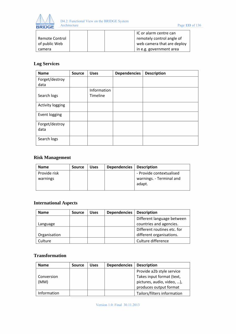
Version 1.0: Final 30.11.2013
D4.2: Functional View on the BRIDGE System Architecture Page 133 of 136
Remote Control of public Web camera
IC or alarm centre can remotely control angle of web camera that are deploy in e.g. government area
Log Services
Name Source Uses Dependencies Description
Forget/destroy data
Search logs Information
Timeline
Activity logging
Event logging
Forget/destroy data
Search logs
Risk Management
Name Source Uses Dependencies Description
Provide risk warnings
‐ Provide contextualised warnings. ‐ Terminal and adapt.
International Aspects
Name Source Uses Dependencies Description
Language Different language between
countries and agencies.
Organisation Different routines etc. for
different organisations.
Culture Culture difference
Transformation
Name Source Uses Dependencies Description
Conversion (MM)
Provide a2b style service Takes input format (text, pictures, audio, video, …), produces output format
Information Tailors/filters information

Version 1.0: Final 30.11.2013
D4.2: Functional View on the BRIDGE System Architecture Page 134 of 136
tailoring from command post to persons in the field according to device, role, specific location, needs, time,…
Information Distribution
Name Source Uses Dependencies Description
?
Site Information Retrieval
Name Source Uses Dependencies Description
External information retrieval
Find existing information sources, e.g. sensors
Building information
Blueprint
Drawing
Image
Land surveying
Information Sharing
Name Source Uses Dependencies Description
datAgent Support data exchange between police/health/fire/other organisations
Alert/Alarm/Notification
Name Source Uses Dependencies Description
Sensor alert Let me know when this
sensor goes below x
Notify ICE
Notify families of people involved Gather medical data of victims
Alarm button 112
Personal alerting
Akinator
Change monitoring

Version 1.0: Final 30.11.2013
D4.2: Functional View on the BRIDGE System Architecture Page 135 of 136
Track & Trace
Name Source
Uses Dependencies Description
Remember this
Tag point of interest
Checked spaces
Anybody that passeseTriage
Track
Sensors
Sensors, geo‐tag
eTriage
Location/Position Track and/or trace specific resources, object, victim.
Geo‐tag Physically relate a
piece of information to a place (Geo‐tag)
Network & Communication
Name Source Uses Dependencies Description
Online Too see if I am
communicating or alone
Opportunistic networking
Communicate via best available channel
QoS
Connect/Disconnect
Ad‐hoc
Availability
Reachability
Service orchestration
Social Media
Name Source Uses Dependencies Description
Social Respond Public needs to organize itself in
emergency situations
Filter false rumours
Identification/reduction/correction of propagation of false rumours in social media (e.g. twitter)
Twitter Communicate quickly in 1
direction
Religious counselling for victims?
Social media Regular posts regarding
situation/disseminate rumours/direct followers

Version 1.0: Final 30.11.2013
D4.2: Functional View on the BRIDGE System Architecture Page 136 of 136
Social media Post about current
situation/warning/avoid area via smart phones, sms
Crowd sourcing Retrieve information from a log of
many peoples communication or questionaries’
Access to social media
Geo ref
Social media access
Provide access to image and video from social media sites on the webBasis for information filtering/aggregation service Requires internet communication/web access
Information filtering/ Aggregation
Inspects image/video from social networks and BRIDGE repositories for material on current emergencyProduces summary of this material for operational picture depending on interests/search of ‘filter assistant’
Expert Localization Services
Name Source Uses Dependencies Description
Request advice
Find expert
Identification Service
Name Source Uses Dependencies Description
?
Modelling Services
Name Source Uses Dependencies Description
Create model (?)
Structural data, Geographical data, Weather data
Access model archive


![LAVOSAR Functional & Technical Architecture · LAVOSAR – Functional & Technical Architecture ... Dr. Oliver Prenzel Rheinmetall Defence Electronics ... [R.C. Martin, 2002]](https://static.fdocuments.in/doc/165x107/5b0916b67f8b9a404d8d5310/lavosar-functional-technical-architecture-functional-technical-architecture.jpg)

