D Series Gear Motors Including Fan Drive Technical Information file2 L1022895 • October 2011 •...
44
OpenCircuitGear MEMBER OF THE SAUER-DANFOSS GROUP ™ D Series Gear Motors Including Fan Drive Technical Information
Transcript of D Series Gear Motors Including Fan Drive Technical Information file2 L1022895 • October 2011 •...

OpenCircuitGearMEMBER OF THE SAUER-DANFOSS GROUP
™D Series Gear MotorsIncluding Fan Drive
Technical Information

L1022895 • October 2011 • Rev E2
OpenCircuitGearMEMBER OF THE SAUER-DANFOSS GROUP
™ D Series Gear Motors Including Fan DriveTechnical InformationRevisions
Table of RevisionsDate Page Changed Rev.February 2009 - First edition AA
November 2009 25 TY shaft uses a #8 woodruf key AB
February 2010 last Fix Osaka address AC
April 2010 various Add reversing fan drive motor BA
November 2010 all Turolla colors CA
July 2011 All TurollaOCG new layout, fonts update, Sauer-Danfoss replacement. D
October 2011 1 Cover page change E
History of Revisions
© 2011 Turolla OpenCircuitGear™. All rights reserved.
TurollaOCG accepts no responsibility for possible errors in catalogs, brochures and other printed material. TurollaOCG reserves the right to alter its products without prior notice. This also applies to products already ordered provided that such alterations can be made without affecting agreed specifi cations. All trademarks in this material are properties of their respective owners. Sauer-Danfoss, Turolla, Turolla OpenCircuitGear, TurollaOCG, OpenCircuitGear, Fast Lane and PLUS+1 are trademarks of the Sauer-Danfoss Group.

L1022895 • October 2011 • Rev E 3
OpenCircuitGearMEMBER OF THE SAUER-DANFOSS GROUP
™ D Series Gear Motors Including Fan DriveTechnical InformationContents
General Information
Operating Parameters
Model Code
Dimension Drawings
Overview ........................................................................................................................................................... 5Features and Benefits .............................................................................................................................. 5Fan Drive Motors ....................................................................................................................................... 5
Features ............................................................................................................................................................. 6Benefits .............................................................................................................................................................. 6System Schematics ........................................................................................................................................ 7Product Features............................................................................................................................................. 8Technical Specifications ............................................................................................................................... 9Fluid Specifications ........................................................................................................................................ 9Sizing Equations ...........................................................................................................................................10
Overview .........................................................................................................................................................11Pressure ............................................................................................................................................................11
Peak Pressure ............................................................................................................................................11Rated Pressure .........................................................................................................................................11System Pressure .......................................................................................................................................11Back Pressure ............................................................................................................................................11Case Drain Pressure ................................................................................................................................11
Temperature and Viscosity ........................................................................................................................12Speed ................................................................................................................................................................12
Temperature .............................................................................................................................................12Viscosity......................................................................................................................................................12
Hydraulic Fluid...............................................................................................................................................13Filtration...........................................................................................................................................................13
Filters ...........................................................................................................................................................13Selecting a Filter ......................................................................................................................................13
Reservoir ..........................................................................................................................................................14Line Sizing .......................................................................................................................................................14Motor Life ........................................................................................................................................................14Motor Shaft Connection ............................................................................................................................15Radial and Axial Loading ...........................................................................................................................15
Order Code .....................................................................................................................................................16Fan drive motor code example ..........................................................................................................16
Mounting Flanges ........................................................................................................................................21Shaft Options .................................................................................................................................................22Port Options ...................................................................................................................................................23Selecting Port Options ...............................................................................................................................24Integrated Reversing Motor with Proportinal Relief and Shock/Anti-cavitation Valves .....25

L1022895 • October 2011 • Rev E4
OpenCircuitGearMEMBER OF THE SAUER-DANFOSS GROUP
™ D Series Gear Motors Including Fan DriveTechnical InformationContents
Options
Reference Literature
Performance Data
Standard Relief Valve ...................................................................................................................................27Anti-c avitation Check Valve .....................................................................................................................29Proportional Relief Valve with Anti-cavitation Valve .......................................................................30
Valve Settings ...........................................................................................................................................31Performance Graphs ..............................................................................................................................32Valve Settings ...........................................................................................................................................32
Fan Drive Motor ............................................................................................................................................34Fan Drive Motor Example: ...................................................................................................................34
Standard Motor .............................................................................................................................................35Standard Motor Example: ....................................................................................................................35
Standard Motor with Split Flange Ports ...............................................................................................36Integrated Reversing Motor with Proportional Relief and Shock/Anti-cavitation Valves ..37
Motor Performance Graphs ......................................................................................................................39
TurollaOCG Fan Drive Related Literature .............................................................................................41
L1022895 • October 2011 • Rev E 5
OpenCircuitGearMEMBER OF THE SAUER-DANFOSS GROUP
™ D Series Gear Motors Including Fan DriveTechnical InformationGeneral Information
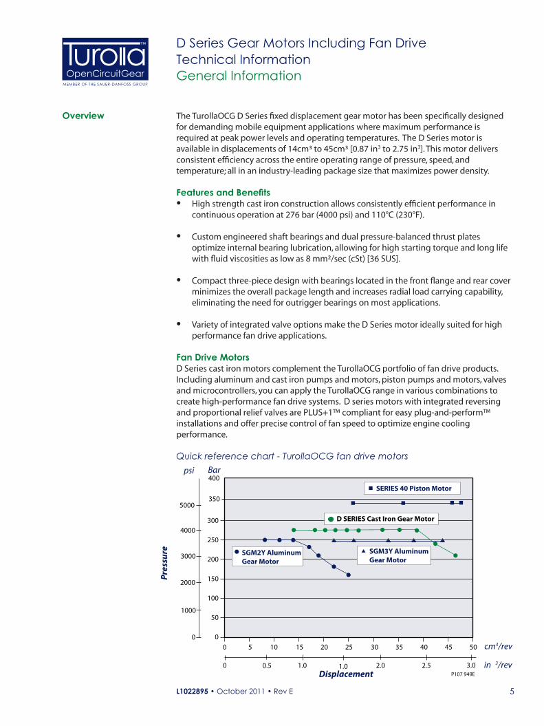
The TurollaOCG D Series fixed displacement gear motor has been specifically designed for demanding mobile equipment applications where maximum performance is required at peak power levels and operating temperatures. The D Series motor is available in displacements of 14cm³ to 45cm³ [0.87 in3 to 2.75 in3]. This motor delivers consistent efficiency across the entire operating range of pressure, speed, and temperature; all in an industry-leading package size that maximizes power density.
Features and Benefits• High strength cast iron construction allows consistently efficient performance in
continuous operation at 276 bar (4000 psi) and 110°C (230°F).
• Custom engineered shaft bearings and dual pressure-balanced thrust plates optimize internal bearing lubrication, allowing for high starting torque and long life with fluid viscosities as low as 8 mm²/sec (cSt) [36 SUS].
• Compact three-piece design with bearings located in the front flange and rear cover minimizes the overall package length and increases radial load carrying capability, eliminating the need for outrigger bearings on most applications.
• Variety of integrated valve options make the D Series motor ideally suited for high performance fan drive applications.
Fan Drive MotorsD Series cast iron motors complement the TurollaOCG portfolio of fan drive products. Including aluminum and cast iron pumps and motors, piston pumps and motors, valves and microcontrollers, you can apply the TurollaOCG range in various combinations to create high-performance fan drive systems. D series motors with integrated reversing and proportional relief valves are PLUS+1™ compliant for easy plug-and-perform™ installations and offer precise control of fan speed to optimize engine cooling performance.
Overview
300
250
200
150
100
50
00 5 10 15 20 25 30 35 40 45 50
Displacement
cm3/rev
Pressure
psi
P107 949E
400
350
SGM3Y AluminumGear Motor
SGM2Y AluminumGear Motor
D SERIES Cast Iron Gear Motor
SERIES 40 Piston Motor
Bar
in 3/rev
5000
4000
3000
2000
1000
0
0.50 1.0 1.0 2.0 2.5 3.0
Quick reference chart - TurollaOCG fan drive motors
L1022895 • October 2011 • Rev E6
OpenCircuitGearMEMBER OF THE SAUER-DANFOSS GROUP
™ D Series Gear Motors Including Fan DriveTechnical InformationGeneral Information
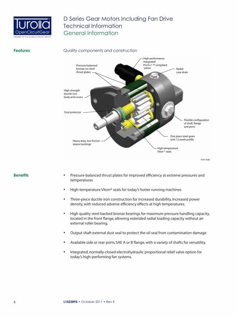
One piece steel gearswith 12 tooth pro�le
Flexible con�gurationof shaft, �angeand ports
Heavy duty, low friction sleeve bushings
High strengthductile ironbody and covers
P107 920E
Pressure balancedbronze-on-steelthrust plates
High performanceintegratedPLUS+1
High temperatureViton ® seals
Dust protector
Radialcase drain
compliantTM
valves
Quality components and constructionFeatures
Benefits • Pressure-balanced thrust plates for improved efficiency at extreme pressures and temperatures
• High-temperature Viton® seals for today’s hotter running machines
• Three-piece ductile iron construction for increased durability, increased power density, with reduced adverse efficiency effects at high temperatures.
• High quality steel backed bronze bearings for maximum pressure handling capacity, located in the front flange, allowing extended radial loading capacity without an external roller bearing.
• Output shaft external dust seal to protect the oil seal from contamination damage
• Available side or rear ports, SAE A or B flange, with a variety of shafts for versatility.
• Integrated, normally-closed electrohydraulic proportional relief valve option for today’s high-performing fan systems.
L1022895 • October 2011 • Rev E 7
OpenCircuitGearMEMBER OF THE SAUER-DANFOSS GROUP
™ D Series Gear Motors Including Fan DriveTechnical InformationGeneral Information
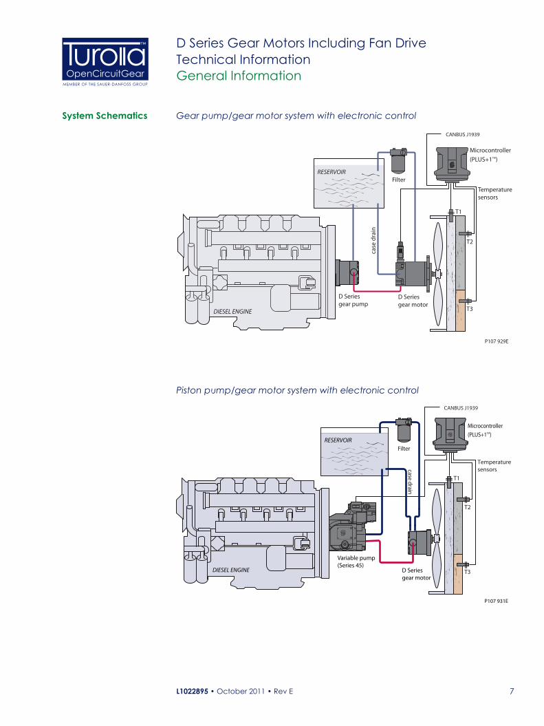
Microcontroller (PLUS+1TM)
Filter
T3
T2
T1
Temperature sensors
D Seriesgear pump
D Series gear motor
RESERVOIR
DIESEL ENGINE
P107 929E
case
dra
in
CANBUS J1939
T3
T2
T1
Temperaturesensors
RESERVOIR
D Seriesgear motor
Microcontroller
(PLUS+1TM)
Filter
DIESEL ENGINE
Variable pump(Series 45)
P107 931E
case drain
CANBUS J1939
System Schematics Gear pump/gear motor system with electronic control
Piston pump/gear motor system with electronic control

L1022895 • October 2011 • Rev E8
OpenCircuitGearMEMBER OF THE SAUER-DANFOSS GROUP
™ D Series Gear Motors Including Fan DriveTechnical InformationGeneral Information
Features Description
Construction Heavy duty ductile iron 3-piece construction
Displacements 14 to 45 cm³ [0.87 to 2.75 in3/rev]
Continuous Pressure 276 bar [4000 psi] to 38 cm³ [2.32 in3/rev]
Peak Pressure 303 bar [4400 psi] to 38 cm³ [2.32 in3/rev]
Speed 600 to 3400 min-1 (rpm) - up to 38cm³
Mounting SAE A two bolt, SAE B two bolt
Shaft (types) SAE straight keyed, 1:8 tapered keyed, splined
Fluid viscosity 8 mm²/sec (cSt) [36 SUS] minimum, 1600 mm²/sec (cSt) [7500 SUS] maximum
Filtration requirement 22/18/13 ISO 4406 at motor inlet
Inlet options SAE O-ring boss, SAE split flange
Fluids Petroleum/mineral based
Operating temperature -40°C [-40°F] minimum for cold start
110°C [230°F] normal operating conditions
115°C [239°F] peak intermittent
Integrated valve options Proportional relief valve, normally closed, 12 Vdc and 24 Vdc
two position directional control valve, 12 Vdc and 24 Vdc
Relief valve
Anti-cavitation check valve
Product Features
Gear Pump(D Series)
T3
T2
T1
ReservoirFilter
CAN Bus
Engine ControlModule (ECM)
Diesel Engine
Temperature Sensors T1, T2, T3
Gear Motor with Integrated Reversingand Modulating Valves(D Series)
Microcontroller (PLUS+1TM)
P108 248E
Case
Dra
in
Gear pump/gear motor system with integrated reversing valveSystem Schematics (continued)
L1022895 • October 2011 • Rev E 9
OpenCircuitGearMEMBER OF THE SAUER-DANFOSS GROUP
™ D Series Gear Motors Including Fan DriveTechnical InformationGeneral Information
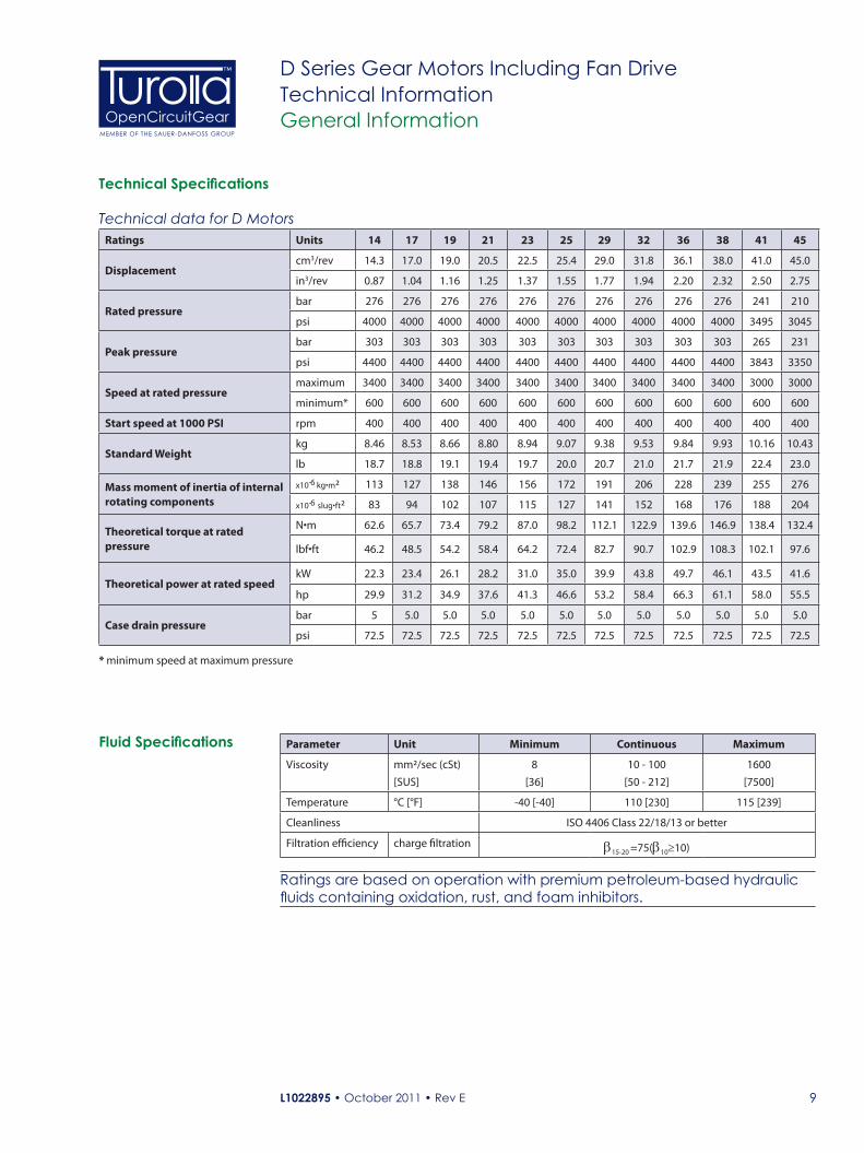
Technical Specifications
Technical data for D MotorsRatings Units 14 17 19 21 23 25 29 32 36 38 41 45
Displacementcm3/rev 14.3 17.0 19.0 20.5 22.5 25.4 29.0 31.8 36.1 38.0 41.0 45.0
in3/rev 0.87 1.04 1.16 1.25 1.37 1.55 1.77 1.94 2.20 2.32 2.50 2.75
Rated pressurebar 276 276 276 276 276 276 276 276 276 276 241 210
psi 4000 4000 4000 4000 4000 4000 4000 4000 4000 4000 3495 3045
Peak pressure bar 303 303 303 303 303 303 303 303 303 303 265 231
psi 4400 4400 4400 4400 4400 4400 4400 4400 4400 4400 3843 3350
Speed at rated pressuremaximum 3400 3400 3400 3400 3400 3400 3400 3400 3400 3400 3000 3000
minimum* 600 600 600 600 600 600 600 600 600 600 600 600
Start speed at 1000 PSI rpm 400 400 400 400 400 400 400 400 400 400 400 400
Standard Weightkg 8.46 8.53 8.66 8.80 8.94 9.07 9.38 9.53 9.84 9.93 10.16 10.43
lb 18.7 18.8 19.1 19.4 19.7 20.0 20.7 21.0 21.7 21.9 22.4 23.0
Mass moment of inertia of internal rotating components
x10-6 kg•m² 113 127 138 146 156 172 191 206 228 239 255 276
x10-6 slug•ft² 83 94 102 107 115 127 141 152 168 176 188 204
Theoretical torque at rated pressure
N•m 62.6 65.7 73.4 79.2 87.0 98.2 112.1 122.9 139.6 146.9 138.4 132.4
lbf•ft 46.2 48.5 54.2 58.4 64.2 72.4 82.7 90.7 102.9 108.3 102.1 97.6
Theoretical power at rated speedkW 22.3 23.4 26.1 28.2 31.0 35.0 39.9 43.8 49.7 46.1 43.5 41.6
hp 29.9 31.2 34.9 37.6 41.3 46.6 53.2 58.4 66.3 61.1 58.0 55.5
Case drain pressurebar 5 5.0 5.0 5.0 5.0 5.0 5.0 5.0 5.0 5.0 5.0 5.0
psi 72.5 72.5 72.5 72.5 72.5 72.5 72.5 72.5 72.5 72.5 72.5 72.5
Parameter Unit Minimum Continuous Maximum
Viscosity mm²/sec (cSt)
[SUS]
8
[36]
10 - 100
[50 - 212]
1600
[7500]
Temperature °C [°F] -40 [-40] 110 [230] 115 [239]
Cleanliness ISO 4406 Class 22/18/13 or better
Filtration efficiency charge filtration β15-20 =75(β10≥10)
Fluid Specifications
Ratings are based on operation with premium petroleum-based hydraulic fluids containing oxidation, rust, and foam inhibitors.
* minimum speed at maximum pressure

L1022895 • October 2011 • Rev E10
OpenCircuitGearMEMBER OF THE SAUER-DANFOSS GROUP
™ D Series Gear Motors Including Fan DriveTechnical InformationGeneral Information
Based on US units
Q = (US gal/min)
M = (lbf•in)
P = = (hp)
n = (min-1(rpm))
SI units [US units]
Vg = Displacement per revolution cm3/rev [in3/rev]pO = Outlet pressure bar [psi]pi = Inlet pressure bar [psi]∆p = pO – pi (system pressure) bar [psi]n = Speed min-1 (rpm)ηv = Volumetric efficiencyηm = Mechanical efficiencyηt = Overall efficiency (ηv • ηm)
Sizing Equations
Variables
Use these formulas to determine the nominal motor size for a specific application.
Vg • n
231 • ηv
Vg • ∆p • ηm
2 • π
Q • ∆p • ηt
1714
Q • 231• ηv
Vg
Based on SI units
Q = (l/min)
M = (N•m)
P = = (kW)
n = (min-1(rpm))
Vg • n
1000 • ηv
Vg • ∆p • ηm
20 • π
Q • ∆p • ηt 600
Q • 1000 • ηv
Vg
M • n
9550
Input flow
Output torque
Output power
Motor speed
M • n
63 025
L1022895 • October 2011 • Rev E 11
OpenCircuitGearMEMBER OF THE SAUER-DANFOSS GROUP
™ D Series Gear Motors Including Fan DriveTechnical InformationOperating Parameters
Peak pressure
Rated pressure
Reaction time (100 ms max)
Time
Pres
sure
P107 861E
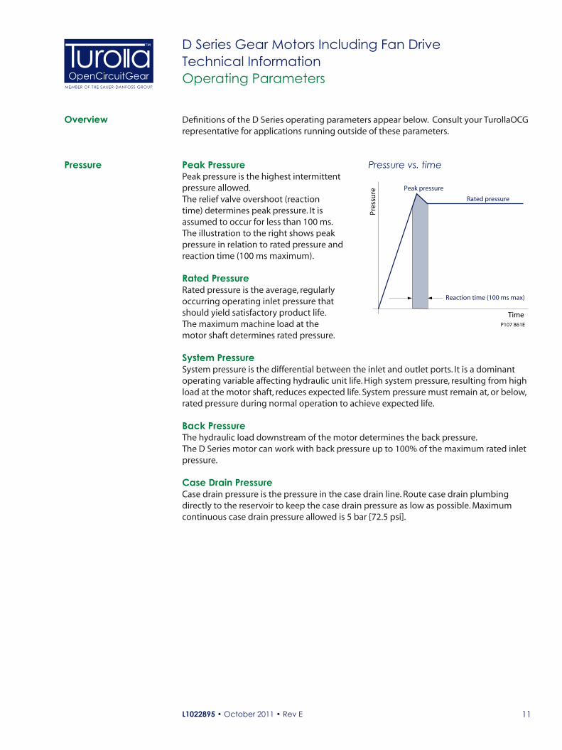
Pressure vs. time
Definitions of the D Series operating parameters appear below. Consult your TurollaOCG representative for applications running outside of these parameters.
Peak PressurePeak pressure is the highest intermittent pressure allowed. The relief valve overshoot (reaction time) determines peak pressure. It is assumed to occur for less than 100 ms. The illustration to the right shows peak pressure in relation to rated pressure and reaction time (100 ms maximum).
Rated PressureRated pressure is the average, regularly occurring operating inlet pressure that should yield satisfactory product life. The maximum machine load at the motor shaft determines rated pressure.
System PressureSystem pressure is the differential between the inlet and outlet ports. It is a dominant operating variable affecting hydraulic unit life. High system pressure, resulting from high load at the motor shaft, reduces expected life. System pressure must remain at, or below, rated pressure during normal operation to achieve expected life.
Back PressureThe hydraulic load downstream of the motor determines the back pressure. The D Series motor can work with back pressure up to 100% of the maximum rated inlet pressure.
Case Drain PressureCase drain pressure is the pressure in the case drain line. Route case drain plumbing directly to the reservoir to keep the case drain pressure as low as possible. Maximum continuous case drain pressure allowed is 5 bar [72.5 psi].
Overview
Pressure
L1022895 • October 2011 • Rev E12
OpenCircuitGearMEMBER OF THE SAUER-DANFOSS GROUP
™ D Series Gear Motors Including Fan DriveTechnical InformationOperating Parameters
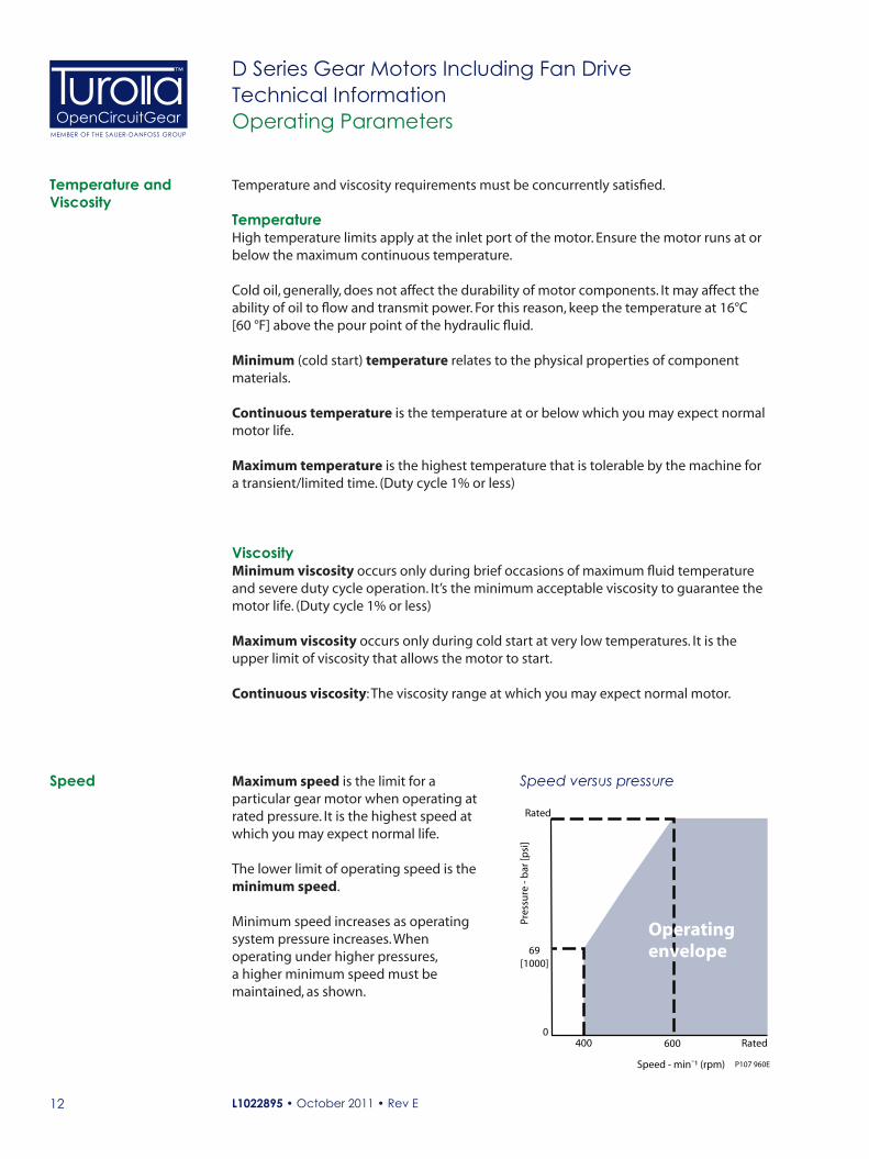
Maximum speed is the limit for a particular gear motor when operating at rated pressure. It is the highest speed at which you may expect normal life.
The lower limit of operating speed is the minimum speed.
Minimum speed increases as operating system pressure increases. When operating under higher pressures, a higher minimum speed must be maintained, as shown.
Speed Speed versus pressure
Rated
69[1000]
Pres
sure
- b
ar [p
si]
0400
P107 960ESpeed - min¯¹ (rpm)
Operatingenvelope
Rated600
Temperature and Viscosity
Temperature and viscosity requirements must be concurrently satisfied.
TemperatureHigh temperature limits apply at the inlet port of the motor. Ensure the motor runs at or below the maximum continuous temperature.
Cold oil, generally, does not affect the durability of motor components. It may affect the ability of oil to flow and transmit power. For this reason, keep the temperature at 16°C [60 °F] above the pour point of the hydraulic fluid.
Minimum (cold start) temperature relates to the physical properties of component materials.
Continuous temperature is the temperature at or below which you may expect normal motor life.
Maximum temperature is the highest temperature that is tolerable by the machine for a transient/limited time. (Duty cycle 1% or less)
ViscosityMinimum viscosity occurs only during brief occasions of maximum fluid temperature and severe duty cycle operation. It’s the minimum acceptable viscosity to guarantee the motor life. (Duty cycle 1% or less)
Maximum viscosity occurs only during cold start at very low temperatures. It is the upper limit of viscosity that allows the motor to start.
Continuous viscosity: The viscosity range at which you may expect normal motor.

L1022895 • October 2011 • Rev E 13
OpenCircuitGearMEMBER OF THE SAUER-DANFOSS GROUP
™ D Series Gear Motors Including Fan DriveTechnical InformationOperating Parameters
Hydraulic Fluid Ratings and data for gear motors are based on operation with premium hydraulic fluids containing oxidation, rust, and foam inhibitors. These fluids must possess good thermal and hydrolytic stability to prevent wear, and corrosion of internal components. Use petroleum/mineral-based fluids. Ensure only clean fluid enters the hydraulic system.
C CautionNever mix hydraulic fluids.
For more information on hydraulic fluid selection, see TurollaOCG publication L1021414 Hydraulic Fluids and Lubricants, Technical Information.
FiltersUse a filter that conforms to Class 22/18/13 of ISO 4406 (or better). It may be on the motor outlet (discharge filtration) or inlet (pressure filtration).
Selecting a FilterWhen selecting a filter, please consider:
• Contaminant ingression rate (determined by factors such as the number of actuators used in the system)
• Generation of contaminants in the system
• Required fluid cleanliness
• Desired maintenance interval
• Filtration requirements of other system components
Measure filter efficiency with a Beta ratio (βX). βx ratio is a measure of filter efficiency defined by ISO 4572. It is the ratio of the number of particles greater than a given diameter (in microns) upstream of the filter to the number of these particles downstream of the filter.
• For discharge filtration with controlled reservoir ingression, use a β35-45 = 75 filter
• For pressure filtration, use a filtration with an efficiency of β10 = 75
Every system is unique. Only a thorough testing and evaluation program can fully validate the filtration system.
Fluid cleanliness level and βX ratioFluid cleanliness level (per ISO 4406) Class 22/18/13 or better
βX ratio (discharge filtration) β35-45 = 75 and β10 = 2
β35-45 = 75 and β10 = 2 β10 = 75
Recommended inlet screen size 100 – 125 μm [0.0039 – 0.0049 in]
Filtration
L1022895 • October 2011 • Rev E14
OpenCircuitGearMEMBER OF THE SAUER-DANFOSS GROUP
™ D Series Gear Motors Including Fan DriveTechnical InformationOperating Parameters
The reservoir provides clean fluid, dissipates heat, removes entrained air, and allows for fluid volume changes associated with fluid expansion. A correctly sized reservoir accommodates maximum volume changes during all system operating modes. It promotes de-aeration of the fluid as it passes through, and accommodates a fluid dwell-time between 60 and 180 seconds, allowing entrained air to escape.
Minimum reservoir capacity depends on the volume required to cool and hold the fluid, allowing for expansion due to temperature changes. A fluid volume of one to three times the motor output flow (per minute) is satisfactory. The minimum recommended reservoir capacity is 125% of the fluid volume.
Put the return-line below the lowest expected fluid level to allow discharge into the reservoir for maximum dwell and efficient de-aeration. A baffle (or baffles) between the return and suction ports promotes de-aeration and accommodates fluid surges.
Choose pipe sizes that accommodate minimum fluid viscosity to reduce system noise, pressure drops and overheating in order to maximize system life and performance. Line velocity should not exceed 5.0 m/s [16.4 ft/s]. Route case drain line direct to tank.
Most systems use hydraulic oil containing 10% dissolved air by volume. Over-areation, or entrained air is the result of flow line restrictions, where the dissolved air comes out of solution, or when air is allowed to leak into the hydraulic circuit. These include inadequate pipe sizes, sharp bends, or elbow fittings, causing reduction of flow-line cross-sectional area. This problem will not occur if these circuit recommendations are followed, rated speed requirements are maintained, and reservoir size and location are adequate.
Motor life is a function of speed, system pressure, and other system parameters (such as fluid quality and cleanliness).
All TurollaOCG gear motors use hydrodynamic journal bearings that rely on an oil film between the gear shaft and bearing surfaces at all times. You can expect long life when this film is sustained through proper system maintenance and operating within recommended limits.
A B10 bearing life expectancy number is generally associated with rolling element bearings. It does not exist for hydrodynamic bearings.
High pressure impacts motor life. When submitting an application for review, provide machine duty cycle data that includes percentages of time at various loads and speeds. We strongly recommend a prototype testing program to verify operating parameters and their impact on life expectancy before finalizing any system design.
Reservoir
Line Sizing
Motor Life
L1022895 • October 2011 • Rev E 15
OpenCircuitGearMEMBER OF THE SAUER-DANFOSS GROUP
™ D Series Gear Motors Including Fan DriveTechnical InformationOperating Parameters
Motor Shaft Connection
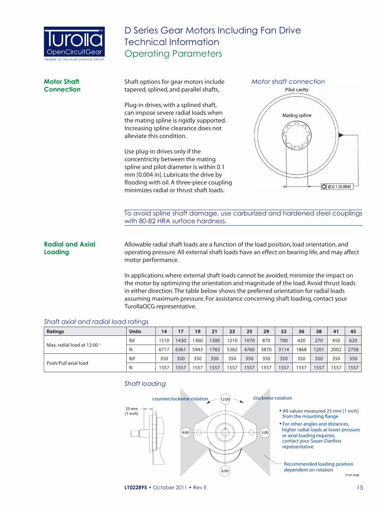
Motor shaft connectionShaft options for gear motors include tapered, splined, and parallel shafts.
Plug-in drives, with a splined shaft, can impose severe radial loads when the mating spline is rigidly supported. Increasing spline clearance does not alleviate this condition.
Use plug-in drives only if the concentricity between the mating spline and pilot diameter is within 0.1 mm [0.004 in]. Lubricate the drive by flooding with oil. A three-piece coupling minimizes radial or thrust shaft loads.
P107 928E
3:00
12:00
9:00
6:00
• All values measured 25 mm [1 inch]from the mounting �ange• For other angles and distances,
higher radial loads at lower pressuresor axial loading inquiriescontact your Sauer-Danfossrepresentative
25 mm[1 inch]
Recommended loading positiondependent on rotation
clockwise rotationcounterclockwise rotation
Shaft axial and radial load ratingsRatings Units 14 17 19 21 23 25 29 32 36 38 41 45
Max. radial load at 12:00 +lbf 1510 1430 1360 1300 1210 1070 870 700 420 270 450 620
N 6717 6361 5943 1783 5382 4760 3870 3114 1868 1201 2002 2758
Push/Pull axial loadlbf 350 350 350 350 350 350 350 350 350 350 350 350
N 1557 1557 1557 1557 1557 1557 1557 1557 1557 1557 1557 1557
To avoid spline shaft damage, use carburized and hardened steel couplings with 80-82 HRA surface hardness.
Allowable radial shaft loads are a function of the load position, load orientation, and operating pressure. All external shaft loads have an effect on bearing life, and may affect motor performance.
In applications where external shaft loads cannot be avoided, minimize the impact on the motor by optimizing the orientation and magnitude of the load. Avoid thrust loads in either direction. The table below shows the preferred orientation for radial loads assuming maximum pressure. For assistance concerning shaft loading, contact your TurollaOCG representative.
Shaft loading
Radial and Axial Loading
L1022895 • October 2011 • Rev E16
OpenCircuitGearMEMBER OF THE SAUER-DANFOSS GROUP
™ D Series Gear Motors Including Fan DriveTechnical InformationModel Code
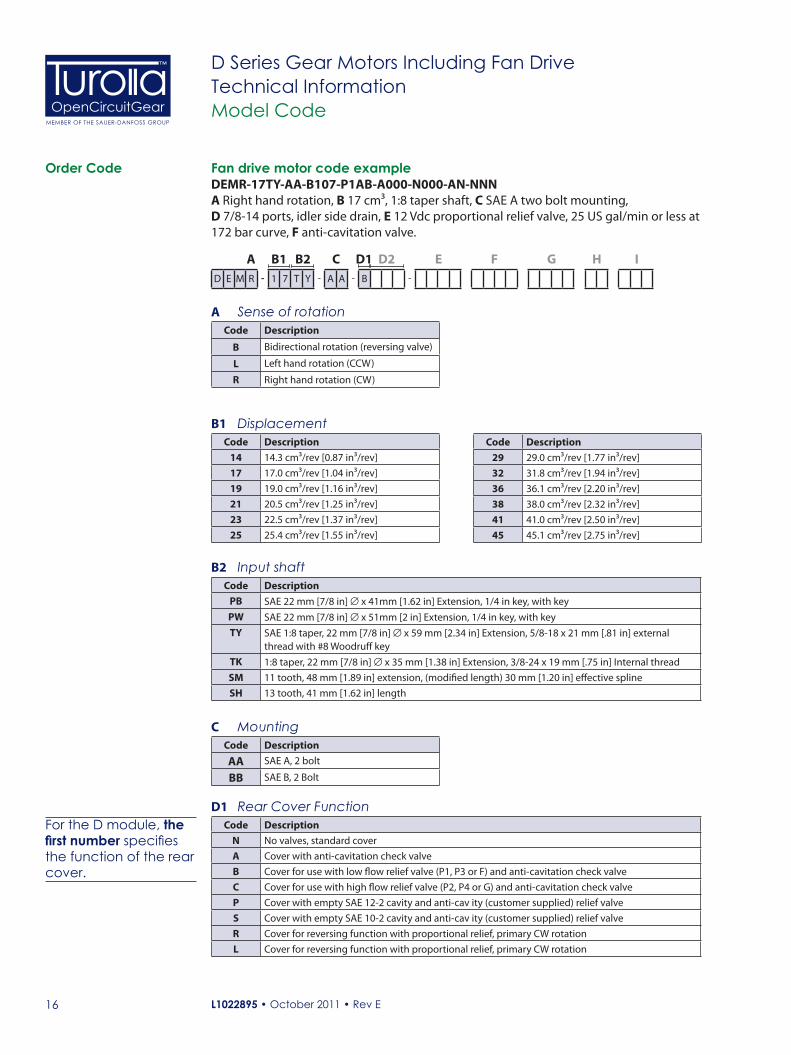
Order Code Fan drive motor code exampleDEMR-17TY-AA-B107-P1AB-A000-N000-AN-NNNA Right hand rotation, B 17 cm³, 1:8 taper shaft, C SAE A two bolt mounting, D 7/8-14 ports, idler side drain, E 12 Vdc proportional relief valve, 25 US gal/min or less at 172 bar curve, F anti-cavitation valve.
A B1 B2 C D1 D2 E F G H ID E M R - 1 7 T Y - A A - B -
A Sense of rotationCode Description
B Bidirectional rotation (reversing valve)
L Left hand rotation (CCW)
R Right hand rotation (CW)
B1 DisplacementCode Description
14 14.3 cm³/rev [0.87 in³/rev]17 17.0 cm³/rev [1.04 in³/rev]19 19.0 cm³/rev [1.16 in³/rev]21 20.5 cm³/rev [1.25 in³/rev]23 22.5 cm³/rev [1.37 in³/rev]25 25.4 cm³/rev [1.55 in³/rev]
B2 Input shaftCode Description
PB SAE 22 mm [7/8 in] ∅ x 41mm [1.62 in] Extension, 1/4 in key, with keyPW SAE 22 mm [7/8 in] ∅ x 51mm [2 in] Extension, 1/4 in key, with keyTY SAE 1:8 taper, 22 mm [7/8 in] ∅ x 59 mm [2.34 in] Extension, 5/8-18 x 21 mm [.81 in] external
thread with #8 Woodruff keyTK 1:8 taper, 22 mm [7/8 in] ∅ x 35 mm [1.38 in] Extension, 3/8-24 x 19 mm [.75 in] Internal threadSM 11 tooth, 48 mm [1.89 in] extension, (modified length) 30 mm [1.20 in] effective splineSH 13 tooth, 41 mm [1.62 in] length
C MountingCode Description
AA SAE A, 2 bolt
BB SAE B, 2 Bolt
D1 Rear Cover FunctionCode Description
N No valves, standard coverA Cover with anti-cavitation check valveB Cover for use with low flow relief valve (P1, P3 or F) and anti-cavitation check valveC Cover for use with high flow relief valve (P2, P4 or G) and anti-cavitation check valveP Cover with empty SAE 12-2 cavity and anti-cav ity (customer supplied) relief valveS Cover with empty SAE 10-2 cavity and anti-cav ity (customer supplied) relief valveR Cover for reversing function with proportional relief, primary CW rotationL Cover for reversing function with proportional relief, primary CW rotation
Code Description 29 29.0 cm³/rev [1.77 in³/rev]32 31.8 cm³/rev [1.94 in³/rev]36 36.1 cm³/rev [2.20 in³/rev]38 38.0 cm³/rev [2.32 in³/rev]41 41.0 cm³/rev [2.50 in³/rev]45 45.1 cm³/rev [2.75 in³/rev]
For the D module, the first number specifies the function of the rear cover.
L1022895 • October 2011 • Rev E 17
OpenCircuitGearMEMBER OF THE SAUER-DANFOSS GROUP
™ D Series Gear Motors Including Fan DriveTechnical InformationModel Code
Order Code (continued)
A B1 B2 C D1 D2 E F G H ID E M R - 1 7 T Y - A A - B 1 0 7 -
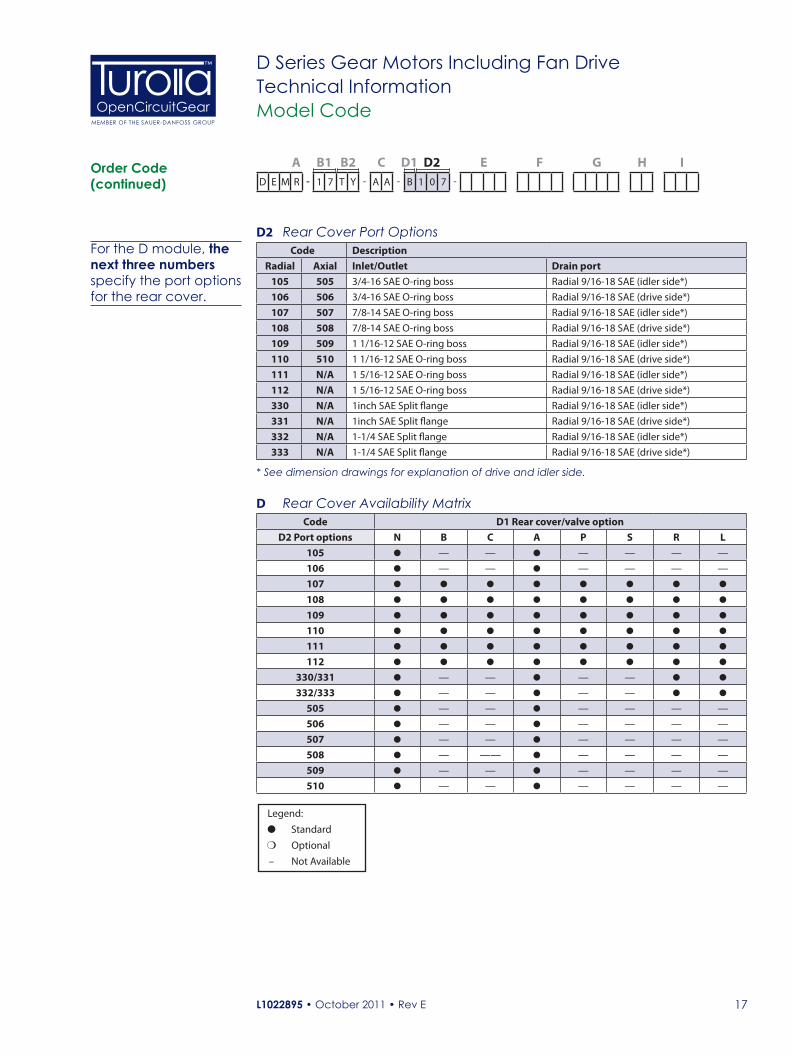
D2 Rear Cover Port OptionsCode Description
Radial Axial Inlet/Outlet Drain port105 505 3/4-16 SAE O-ring boss Radial 9/16-18 SAE (idler side*)106 506 3/4-16 SAE O-ring boss Radial 9/16-18 SAE (drive side*)107 507 7/8-14 SAE O-ring boss Radial 9/16-18 SAE (idler side*)108 508 7/8-14 SAE O-ring boss Radial 9/16-18 SAE (drive side*)109 509 1 1/16-12 SAE O-ring boss Radial 9/16-18 SAE (idler side*)110 510 1 1/16-12 SAE O-ring boss Radial 9/16-18 SAE (drive side*)111 N/A 1 5/16-12 SAE O-ring boss Radial 9/16-18 SAE (idler side*)112 N/A 1 5/16-12 SAE O-ring boss Radial 9/16-18 SAE (drive side*)330 N/A 1inch SAE Split flange Radial 9/16-18 SAE (idler side*)331 N/A 1inch SAE Split flange Radial 9/16-18 SAE (drive side*)332 N/A 1-1/4 SAE Split flange Radial 9/16-18 SAE (idler side*)333 N/A 1-1/4 SAE Split flange Radial 9/16-18 SAE (drive side*)
* See dimension drawings for explanation of drive and idler side.
D Rear Cover Availability MatrixCode D1 Rear cover/valve option
D2 Port options N B C A P S R L105 — — — — — —
106 — — — — — —
107
108
109
110
111
112
330/331 — — — —
332/333 — — — —
505 — — — — — —
506 — — — — — —
507 — — — — — —
508 — —— — — — —
509 — — — — — —
510 — — — — — —
For the D module, the next three numbers specify the port options for the rear cover.
Legend:
� Standard
� Optional
– Not Available

L1022895 • October 2011 • Rev E18
OpenCircuitGearMEMBER OF THE SAUER-DANFOSS GROUP
™ D Series Gear Motors Including Fan DriveTechnical Information
Order Code (continued)
Model Code
A B1 B2 C D1 D2 E F G H ID E M R - 1 7 T Y - A A - B 1 0 7 - P 1 A B
E Relief Valve Availability
Code DescriptionPressure bar [psi]
Compatible with D1 - Rear cover functionN B C A P S R L
N000 No relief valve N/A — — — —
R000 Reversing, with proportional relief See module G — — — — — —
F138
F style - low flow, fixed setting pressure relief valve (non-reversing)
138 [2000] — — — — — — —
F172 172 [2500] — — — — — — —
F207 207 [3000] — — — — — — —
F241 241 [3500] — — — — — — —
F276 276 [4000] — — — — — — —
G138
G style - high flow, fixed setting pressure relief valve (non-reversing)
138 [2000] — — — — — — —
G172 172 [2500] — — — — — — —
G207 207 [3000] — — — — — — —
G241 241 [3500] — — — — — — —
G276 276 [4000] — — — — — — —
P1AA
P1 style - low flow, proportional relief valve 12 Vdc (non-reversing)
138 [2000] — — — — — — —
P1AB 172 [2500] — — — — — — —
P1AC 207 [3000] — — — —— — —— —
P1AD 241 [3500] — — — — — — —
P1AF 276 [4000] — — — — — — —
P2BA
P2 style - high flow, proportional relief valve 12 Vdc (non-reversing)
138 [2000] — — — — — — —
P2BB 172 [2500] — — — — — — —
P2BC 207 [3000] — — — — — — —
P2BD 241 [3500] — — — — — — —
P2BF 276 [4000] — — — — — — —
P3AA
P3 style - low flow, proportional relief valve 24 Vdc (non-reversing)
138 [2000] — — — — — — —
P3AB 172 [2500] — — — — — — —
P3AC 207 [3000] — — — — — — —
P3AD 241 [3500] — — — — — — —
P3AF 276 [4000] — — — — — — —
P4BA
P4 style - high flow, proportional relief valve 24 Vdc (non-reversing)
138 [2000] — — — — — — —
P4BB 172 [2500] — — — — — — —
P4BC 207 [3000] — — — — — — —
P4BD 241 [3500] — — — — — — —
P4BF 276 [4000] — — — — — — —
Legend:
� Standard
� Optional
– Not Available

L1022895 • October 2011 • Rev E 19
OpenCircuitGearMEMBER OF THE SAUER-DANFOSS GROUP
™ D Series Gear Motors Including Fan DriveTechnical Information
Order Code (continued)
Model Code
Legend:
� Standard
� Optional
– Not Available
A B1 B2 C D1 D2 E F G H ID E M R - 1 7 T Y - A A - B 1 0 7 -
F Anti-cavitation/Shock Valve FunctionCompatible with D1 - Rear cover option
F A B C N P S R LNo valves N000 — — — —
Anti-cavitation valve A000
Shock with Anti-cavitation S300 — — — — — —
Units with integrated reversing are bi-directional motors, however, valves are rotation specific. User must specify DEMB rotation and R or L rear cover. Integrated reversing also requires R000 relief and S300 anti-cavitation/shock valves.
G Integrated Reversing Modulating Function
Code DescriptionPressure bar [psi]
A B C N P S R L
N000 No integrated reversing valve N/A — —
A1AA
D03 Directional Valve P1 Style - Proportional relief valve 12 VDC
138 [2000] — — — — — —
A1AB 172 [2500] — — — — — —
A1AC 207 [3000] — — — — — —
A1AD 241 [3500] — — — — — —
A1AF 276 [4000] — — — — — —
A2AA
D03 Directional Valve P3 Style - Proportional relief valve 24 VDC
138 [2000] — — — — — —
A2AB 172 [2500] — — — — — —
A2AC 207 [3000] — — — — — —
A2AD 241 [3500] — — — — — —
A2AF 276 [4000] — — — — — —
B1AA
D05 Directional Valve P2 Style - Proportional relief valve 12 VDC
138 [2000] — — — — — —
B1AB 172 [2500] — — — — — —
B1AC 207 [3000] — — — — — —
B1AD 241 [3500] — — — — — —
B1AF 276 [4000] — — — — — —
B2AA
D05 Directional Valve P4 Style - Proportional relief valve 24 VDC
138 [2000] — — — — — —
B2AB 172 [2500] — — — — — —
B2AC 207 [3000] — — — — — —
B2AD 241 [3500] — — — — — —
B2AF 276 [4000] — — — — — —
L1022895 • October 2011 • Rev E20
OpenCircuitGearMEMBER OF THE SAUER-DANFOSS GROUP
™ D Series Gear Motors Including Fan DriveTechnical InformationModel Code
Order Code (continued)
A B1 B2 C D1 D2 E F G H ID E M R - 1 7 T Y - A A - B 1 0 7 -
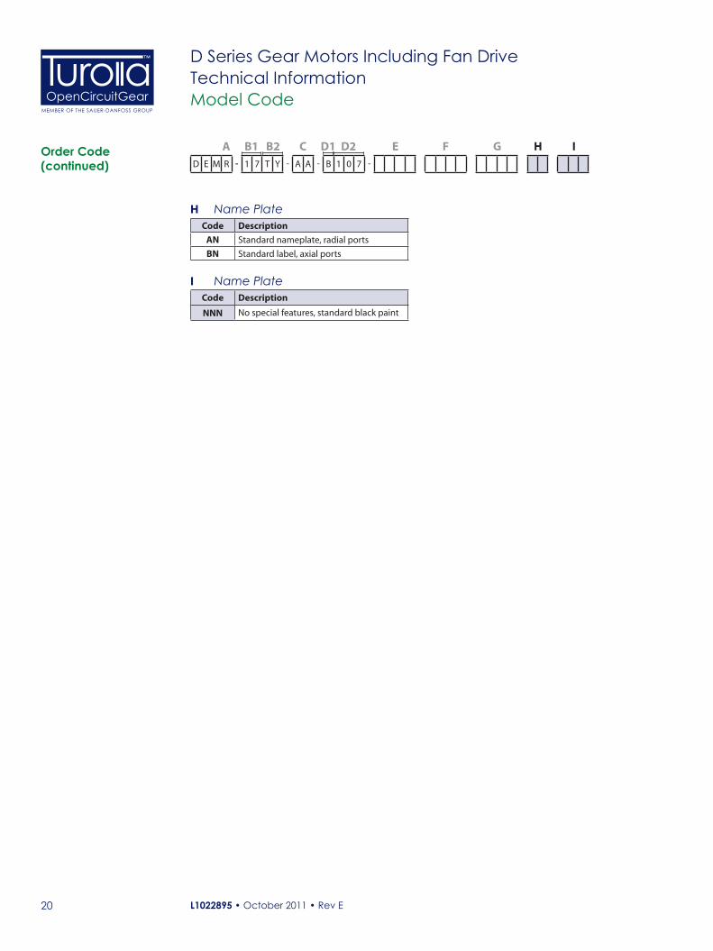
H Name PlateCode Description
AN Standard nameplate, radial portsBN Standard label, axial ports
I Name PlateCode Description
NNN No special features, standard black paint
L1022895 • October 2011 • Rev E 21
OpenCircuitGearMEMBER OF THE SAUER-DANFOSS GROUP
™ D Series Gear Motors Including Fan DriveTechnical InformationOptions
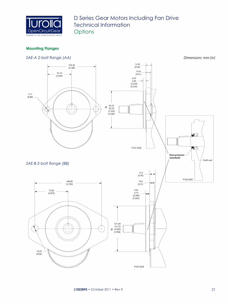
Mounting Flanges
SAE-A 2-bolt flange (AA)
106.38[4.188]
P107 926E
11.7[0.46]
53.19[2.094]
12.45[0.49]
10.41[0.41]
6.355.84
[0.250][0.230]
82.5582.50
[3.250][3.248]
SAE-B 2-bolt flange (BB)
P107 927E
146.05[5.750]
73.02[2.875]
14.23[0.56]
9.659.14
[0.380][0.360]
12.4[0.49]
10.4[0.41]
101.60101.55[4.000][3.998]
Dimensions mm [in]
P108 260E
Shaft seal
Dust protector(standard)
L1022895 • October 2011 • Rev E22
OpenCircuitGearMEMBER OF THE SAUER-DANFOSS GROUP
™ D Series Gear Motors Including Fan DriveTechnical InformationOptions
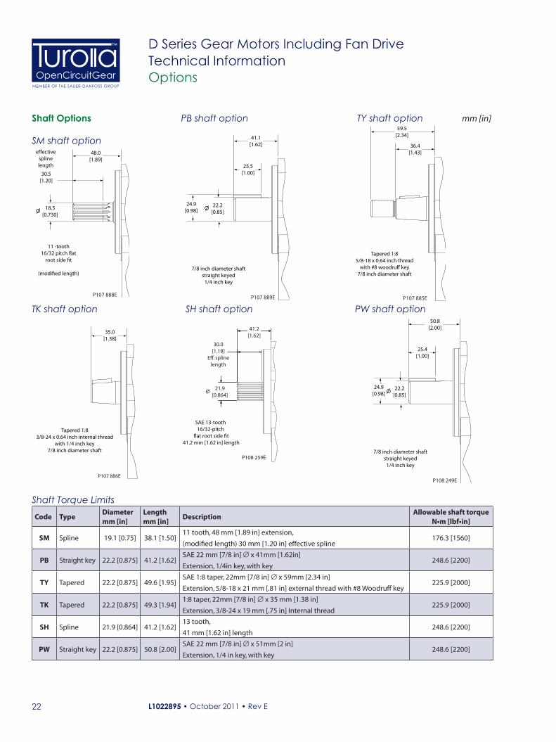
Shaft Options59.5
[2.34]
Tapered 1:85/8-18 x 0.64 inch thread
with #8 woodru� key7/8 inch diameter shaft
36.4[1.43]
P107 885E
35.0[1.38]
Tapered 1:83/8-24 x 0.64 inch internal thread
with 1/4 inch key7/8 inch diameter shaft
P107 886E
41.1[1.62]
25.5[1.00]
22.2[0.85]
24.9[0.98]
7/8 inch diameter shaftstraight keyed
1/4 inch key
P107 889E
mm [in]
48.0[1.89]
30.5[1.20]
e�ectivesplinelength
18.5[0.730]
11 -tooth16/32 pitch �at
root side �t
(modi�ed length)
P107 888E
TY shaft option
TK shaft option
SM shaft option
PB shaft option
Shaft Torque Limits
Code TypeDiametermm [in]
Lengthmm [in]
DescriptionAllowable shaft torque
N•m [lbf•in]
SM Spline 19.1 [0.75] 38.1 [1.50]11 tooth, 48 mm [1.89 in] extension,
(modified length) 30 mm [1.20 in] effective spline176.3 [1560]
PB Straight key 22.2 [0.875] 41.2 [1.62]SAE 22 mm [7/8 in] ∅ x 41mm [1.62in]
Extension, 1/4in key, with key248.6 [2200]
TY Tapered 22.2 [0.875] 49.6 [1.95]SAE 1:8 taper, 22mm [7/8 in] ∅ x 59mm [2.34 in]
Extension, 5/8-18 x 21 mm [.81 in] external thread with #8 Woodruff key225.9 [2000]
TK Tapered 22.2 [0.875] 49.3 [1.94]1:8 taper, 22mm [7/8 in] ∅ x 35 mm [1.38 in]
Extension, 3/8-24 x 19 mm [.75 in] Internal thread225.9 [2000]
SH Spline 21.9 [0.864] 41.2 [1.62]13 tooth,
41 mm [1.62 in] length248.6 [2200]
PW Straight key 22.2 [0.875] 50.8 [2.00]SAE 22 mm [7/8 in] ∅ x 51mm [2 in]
Extension, 1/4 in key, with key248.6 [2200]
50.8[2.00]
25.4[1.00]
22.2[0.85]
24.9[0.98]
7/8 inch diameter shaftstraight keyed
1/4 inch key
P108 249E
PW shaft optionSH shaft option
SAE 13-tooth 16/32-pitch
�at root side �t41.2 mm [1.62 in] length
P108 259E
Ø 21.9
[0.864]
30.0[1.18]
Eff. splinelength
41.2[1.62]
L1022895 • October 2011 • Rev E 23
OpenCircuitGearMEMBER OF THE SAUER-DANFOSS GROUP
™ D Series Gear Motors Including Fan DriveTechnical InformationOptions
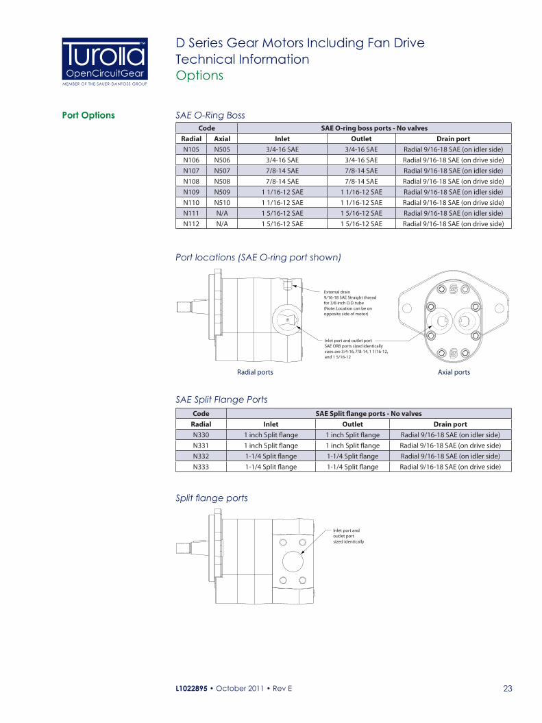
Port Options SAE O-Ring Boss
Port locations (SAE O-ring port shown)
P107 904E
External drain9/16-18 SAE Straight threadfor 3/8 inch O.D. tube(Note: Location can be onopposite side of motor)
Inlet port and outlet portSAE ORB ports sized identicallysizes are 3/4-16, 7/8-14, 1 1/16-12, and 1 5/16-12
Code SAE O-ring boss ports - No valvesRadial Axial Inlet Outlet Drain port
N105 N505 3/4-16 SAE 3/4-16 SAE Radial 9/16-18 SAE (on idler side)
N106 N506 3/4-16 SAE 3/4-16 SAE Radial 9/16-18 SAE (on drive side)
N107 N507 7/8-14 SAE 7/8-14 SAE Radial 9/16-18 SAE (on idler side)
N108 N508 7/8-14 SAE 7/8-14 SAE Radial 9/16-18 SAE (on drive side)
N109 N509 1 1/16-12 SAE 1 1/16-12 SAE Radial 9/16-18 SAE (on idler side)
N110 N510 1 1/16-12 SAE 1 1/16-12 SAE Radial 9/16-18 SAE (on drive side)
N111 N/A 1 5/16-12 SAE 1 5/16-12 SAE Radial 9/16-18 SAE (on idler side)
N112 N/A 1 5/16-12 SAE 1 5/16-12 SAE Radial 9/16-18 SAE (on drive side)
SAE Split Flange PortsCode SAE Split flange ports - No valves
Radial Inlet Outlet Drain port
N330 1 inch Split flange 1 inch Split flange Radial 9/16-18 SAE (on idler side)
N331 1 inch Split flange 1 inch Split flange Radial 9/16-18 SAE (on drive side)
N332 1-1/4 Split flange 1-1/4 Split flange Radial 9/16-18 SAE (on idler side)
N333 1-1/4 Split flange 1-1/4 Split flange Radial 9/16-18 SAE (on drive side)
P107 942E
Inlet port and outlet portsized identically
Split flange ports
Radial ports Axial ports
L1022895 • October 2011 • Rev E24
OpenCircuitGearMEMBER OF THE SAUER-DANFOSS GROUP
™ D Series Gear Motors Including Fan DriveTechnical InformationOptions
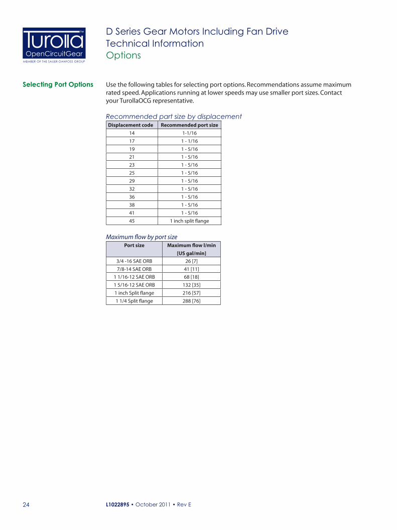
Selecting Port Options Use the following tables for selecting port options. Recommendations assume maximum rated speed. Applications running at lower speeds may use smaller port sizes. Contact your TurollaOCG representative.
Recommended part size by displacementDisplacement code Recommended port size
14 1-1/16
17 1 - 1/16
19 1 - 5/16
21 1 - 5/16
23 1 - 5/16
25 1 - 5/16
29 1 - 5/16
32 1 - 5/16
36 1 - 5/16
38 1 - 5/16
41 1 - 5/16
45 1 inch split flange
Maximum flow by port sizePort size Maximum flow l/min
[US gal/min]
3/4 -16 SAE ORB 26 [7]
7/8-14 SAE ORB 41 [11]
1 1/16-12 SAE ORB 68 [18]
1 5/16-12 SAE ORB 132 [35]
1 inch Split flange 216 [57]
1 1/4 Split flange 288 [76]

L1022895 • October 2011 • Rev E 25
OpenCircuitGearMEMBER OF THE SAUER-DANFOSS GROUP
™ D Series Gear Motors Including Fan DriveTechnical InformationOptions
Integrated Reversing Motor with Proportinal Relief and Shock/Anti-cavitation Valves
Features and Benefits• Solenoid reversing valve directs flow to either side of the motor to reverse fan
rotation. The valve uses an open transition spool to reduce the likelihood of pressure spikes during sudden reversals and is available in two flow ranges to minimize losses.
• Integrated proportional pressure control to modulate fan speed by modulating pressure across the fan motor. The valve is available in two flow ranges and is normally closed to ensure full fan speed in case of loss of electrical signal.
• Dual shock valves limit pressure spikes in both forward and reverse rotation and eliminates damage to the system during sudden fan reversals
• Dual anti-cavitation check valves bypass motor flow during fan deceleration.• The motor is PLUS+1TM compliant allowing the user to take advantage of automatic
cleaning sequences available on TurollaOCG microcontrollers• Valves are qualified to 276 bar (4000 psi) and are contained in a steel body to ensure
maximum performance and long life at elevated temperatures and pressures. • Deutsch connectors, Viton® seals and shaft dust protector are standard for operation
in severe environments• Integrated valve design provides short length and high power density in a compact
package while minimizing installation costs.
The D Series Motor can be configured to include an integrated reversing option for high performance fan drive systems requiring variable speed and reversal of fan direction to purge coolers and radiators.
Technical DataThe directional control valve uses an internal spring to bias spool position and direct flow to the motor. As a result, the preferred motor rotation must be specified in the model code. A right hand motor would be biased for clockwise rotation with counter-clockwise reversing, while a left hand motor would be biased for counter-clockwise rotation with clockwise reversing.
The reversing valve function is available in two flow ratings. The D05 directional valve is standard with the high flow proportional valve, while the D03 directional valve is standard with the low flow proportional valve. Use the P-T pressure drop curves to minimize pressure drop at maximum flow conditions.
P108 250E
P
T
P
T B
A
D
1
2
L1022895 • October 2011 • Rev E26
OpenCircuitGearMEMBER OF THE SAUER-DANFOSS GROUP
™ D Series Gear Motors Including Fan DriveTechnical InformationOptions
Integrated Reversing with Proportinal Relief and Shock/Anti-cavitation Valves (continued)
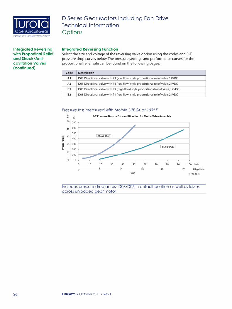
Integrated Reversing FunctionSelect the size and voltage of the reversing valve option using the codes and P-T pressure drop curves below. The pressure settings and performance curves for the proportional relief vale can be found on the following pages.
Code Description
A1 D03 Directional valve with P1 (low flow) style proportional relief valve, 12VDC
A2 D03 Directional valve with P3 (low flow) style proportional relief valve, 24VDC
B1 D05 Directional valve with P2 (high flow) style proportional relief valve, 12VDC
B2 D05 Directional valve with P4 (low flow) style proportional relief valve, 24VDC
0
100
200
300
400
500
600
700
0 10 20 30 40 50 60 70 80 90 100
Pres
sure
loss
Flow P108 251E
P-T Pressure Drop in Forward Direction for Motor/Valve Assembly
l/min
psi
Bar
0
10
20
30
40
50
A1, A2 (D03)
5 10 15 20 25 US gal/min0
B1, B2 (D05)
Pressure loss measured with Mobile DTE 24 at 105° F
Includes pressure drop across D03/D05 in default position as well as losses across unloaded gear motor

L1022895 • October 2011 • Rev E 27
OpenCircuitGearMEMBER OF THE SAUER-DANFOSS GROUP
™ D Series Gear Motors Including Fan DriveTechnical InformationOptions
Standard Relief Valve
P107 946E
Schematic - Motor with standard relief valve with optional anti-cavitation valve
The fixed-setting pressure relief valve limits maximum fan speed and protects the motor from over-pressurization.
Mount the motor so the relief valve is below the reservoir oil level. Keep the relief valve in a horizontal position. Be sure to bleed the system to remove entrained air.
Standard relief valve
P107 938E
Anti-cavitation check valve
Section A-A
A
A
Any modification to the valve to change the factory setting will void product warranty.
Relief valve codesCode Desctiption
F Relief valve internally drained - applications with 95 l/min [26 US gal/min] or less flow
G Relief valve internally drained - applications with 96-190 l/min [26-50 US gal/min] flow
The fixed-setting relief valve can only be used to limit fan speed in one rotational direction. As a result, the preferred motor rotation must be specified in the model code - DEML or DEMR.
L1022895 • October 2011 • Rev E28
OpenCircuitGearMEMBER OF THE SAUER-DANFOSS GROUP
™ D Series Gear Motors Including Fan DriveTechnical InformationOptions
0
500
1000
1500
2000
2500
3000
3500
4000
4500
5000
0 5 10 15 20 25 30
By-pass flow P107 918E
US gal/min
l/min0 30 40 50 60 70 80 90 100
Pre
ssu
re
psi
bar
0
50
100
150
200
250
300
1102010
138
172
207
241
276
By-pass flow P107 919E
US gal/min
l/min0 30 40 50 60 70 80 90 100 140 150130
0 5 10 15 20 25 30 35 40 450
500
1000
1500
2000
2500
3000
3500
4000
4500
Pre
ssu
re
psi
bar
0
50
100
150
200
250
300
5000
1601201102010
138
172
207
241
276
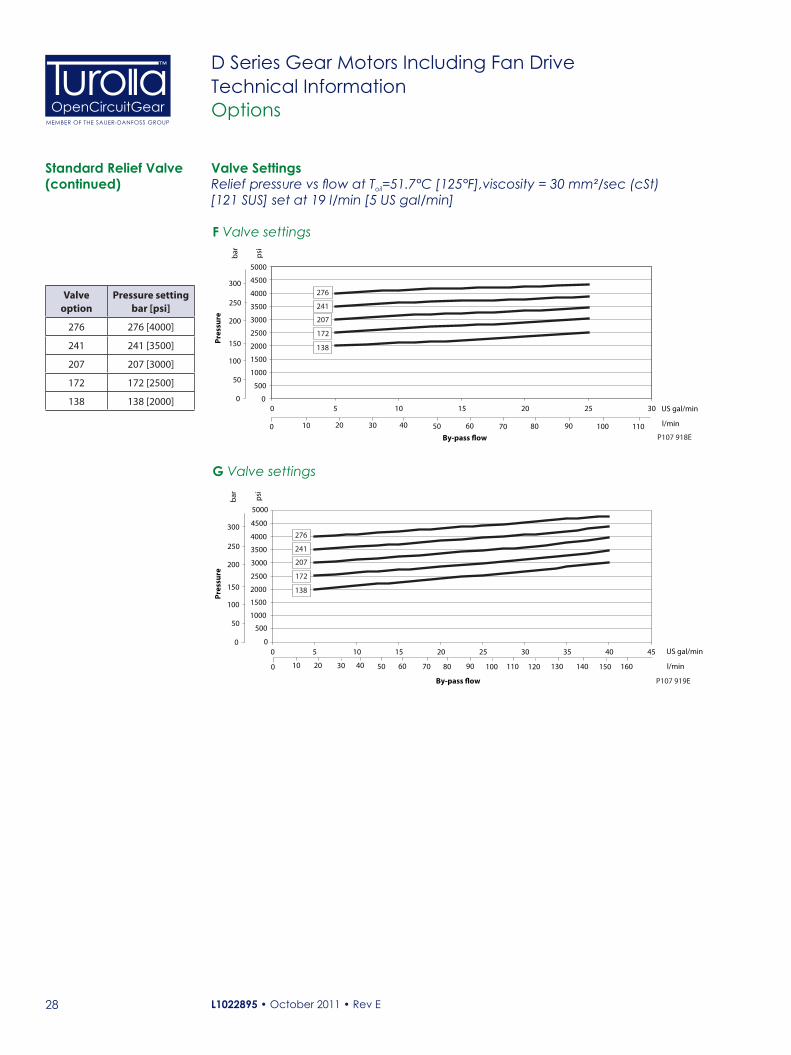
F Valve settings
G Valve settings
Valve SettingsStandard Relief Valve (continued)
Valve option
Pressure setting bar [psi]
276 276 [4000]
241 241 [3500]
207 207 [3000]
172 172 [2500]
138 138 [2000]
Relief pressure vs flow at Toil=51.7°C [125°F],viscosity = 30 mm²/sec (cSt) [121 SUS] set at 19 l/min [5 US gal/min]
L1022895 • October 2011 • Rev E 29
OpenCircuitGearMEMBER OF THE SAUER-DANFOSS GROUP
™ D Series Gear Motors Including Fan DriveTechnical InformationOptions
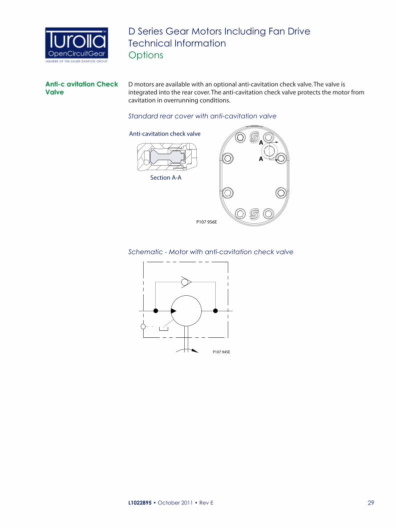
Anti-c avitation Check Valve
D motors are available with an optional anti-cavitation check valve. The valve is integrated into the rear cover. The anti-cavitation check valve protects the motor from cavitation in overrunning conditions.
P107 945E
Schematic - Motor with anti-cavitation check valve
P107 956E
Anti-cavitation check valve
Section A-A
A
A
Standard rear cover with anti-cavitation valve
L1022895 • October 2011 • Rev E30
OpenCircuitGearMEMBER OF THE SAUER-DANFOSS GROUP
™ D Series Gear Motors Including Fan DriveTechnical InformationOptions
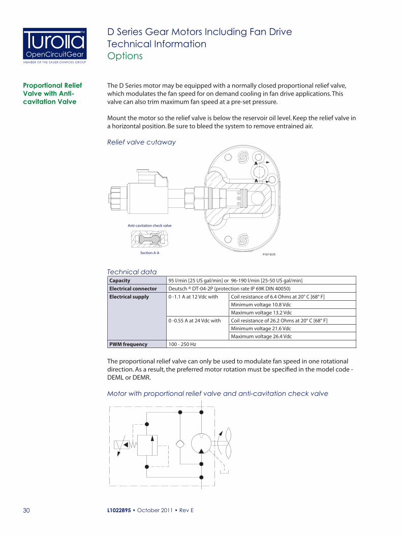
Proportional Relief Valve with Anti-cavitation Valve
2466
Motor with proportional relief valve and anti-cavitation check valve
The D Series motor may be equipped with a normally closed proportional relief valve, which modulates the fan speed for on demand cooling in fan drive applications. This valve can also trim maximum fan speed at a pre-set pressure.
Mount the motor so the relief valve is below the reservoir oil level. Keep the relief valve in a horizontal position. Be sure to bleed the system to remove entrained air.
Relief valve cutaway
P107 937E
Anti-cavitation check valve
Section A-A
A
A
Technical dataCapacity 95 l/min [25 US gal/min] or 96-190 l/min [25-50 US gal/min]
Electrical connector Deutsch ® DT-04-2P (protection rate IP 69K DIN 40050)
Electrical supply 0 -1.1 A at 12 Vdc with Coil resistance of 6.4 Ohms at 20° C [68° F]
Minimum voltage 10.8 Vdc
Maximum voltage 13.2 Vdc
0 -0.55 A at 24 Vdc with Coil resistance of 26.2 Ohms at 20° C [68° F]
Minimum voltage 21.6 Vdc
Maximum voltage 26.4 Vdc
PWM frequency 100 - 250 Hz
The proportional relief valve can only be used to modulate fan speed in one rotational direction. As a result, the preferred motor rotation must be specified in the model code - DEML or DEMR.

L1022895 • October 2011 • Rev E 31
OpenCircuitGearMEMBER OF THE SAUER-DANFOSS GROUP
™ D Series Gear Motors Including Fan DriveTechnical InformationOptions
Proportional Relief Valve (continued)
0500
100015002000250030003500400045005000
Bypass �ow
Del
ta P
ress
ure
P107 909E
0 5 10 15 20 25 30 US gal/min
l/min100 20 30 40 50 60 70 80 90 100
psi
Bar
0
50
100
150
200
250
300
350
AAABACADAF
P1 and P3 valve settings, (low flow)
P107 911E
0 5 10 15 20 25 30 35 40 450
500100015002000250030003500400045005000
Bypass �ow
Del
ta p
ress
ure
US gal/min
l/min0 20 40
psi
Bar
0
50
100
150
200
250
300
350
80 100 120 14060 160
- 0 B
ar+
7 Ba
r
BABBBCBDBF
P2 and P4 valve settings, (high flow)
Valve Settings
Select proportional relief valve setting using the pressure vs. bypass flow graphs. Any modification to the valve to change the factory setting will void product warranty.
Valve option
Pressure setting bar [psi]
BF 276 [4000]
BD 241 [3500]
BC 207 [3000]
BB 172 [2500]
BA 138 [2000]
Valve option
Pressure setting bar [psi]
AF 276 [4000]
AD 241 [3500]
AC 207 [3000]
AB 172 [2500]
AA 138 [2000]
Code Description
P1 12 Vdc Proportional relief valve internally drained, low flow
P2 12 Vdc Proportional relief valve internally drained, high flow
P3 24 Vdc Proportional relief valve internally drained, low flow
P4 24 Vdc Proportional relief valve internally drained, high flow
L1022895 • October 2011 • Rev E32
OpenCircuitGearMEMBER OF THE SAUER-DANFOSS GROUP
™ D Series Gear Motors Including Fan DriveTechnical InformationOptions
Proportional Relief Valve (continued)
Code DesctiptionP1 12 Vdc Proportional relief valve internally drained - with 95 l/min [25 US gal/min] or less flow
P2 12 Vdc Proportional relief valve internally drained - with 96-190 l/min[26-50 US gal/min] flow
P3 24 Vdc Proportional relief valve internally drained - with 95 l/min [25 US gal/min] or less flow
P4 24 Vdc Proportional relief valve internally drained - with 96-190 l/min[26-50 US gal/min] flow
Valve Settings
Any modification to the valve to change the factory setting will void product warranty.
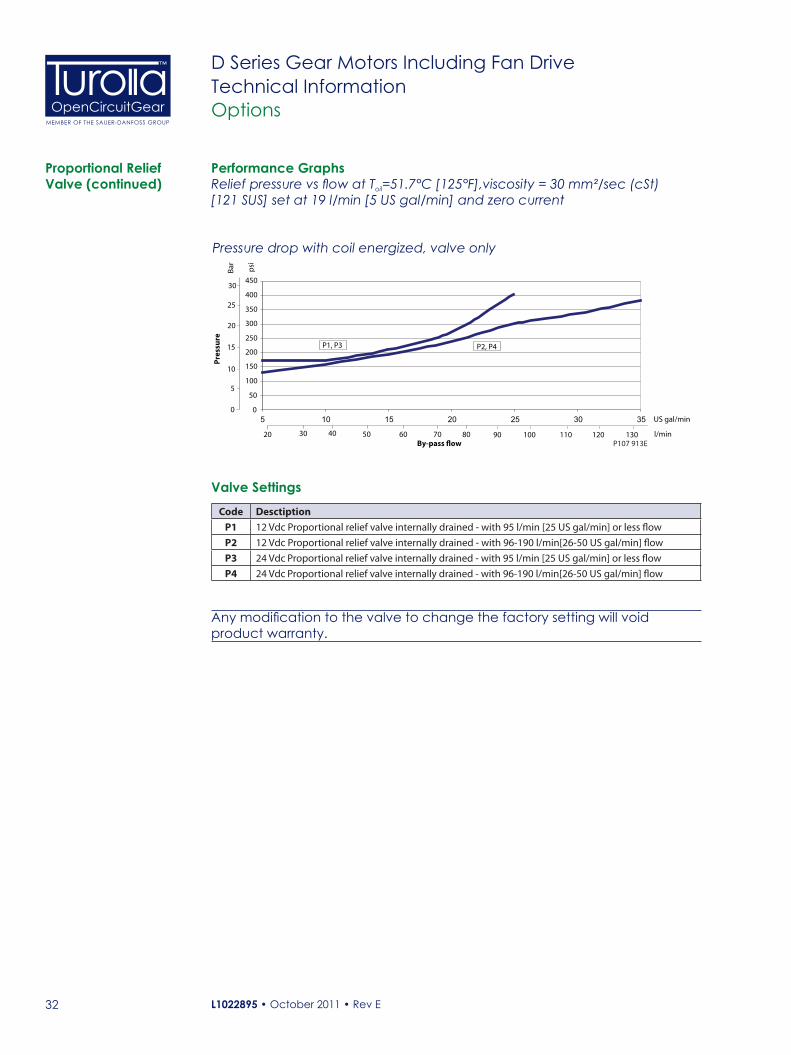
Performance Graphs
5 10 15 20 25 30 35
By-pass �ow
Pres
sure
P107 913E
US gal/min
l/min20 30 40 50 60 70 80 90
psi
Bar
0
5
10
15
20
25
30
0
50
100
150
200
250
300
350
400
450
100 110 120 130
P1, P3 P2, P4
Pressure drop with coil energized, valve only
Relief pressure vs flow at Toil=51.7°C [125°F],viscosity = 30 mm²/sec (cSt) [121 SUS] set at 19 l/min [5 US gal/min] and zero current
L1022895 • October 2011 • Rev E 33
OpenCircuitGearMEMBER OF THE SAUER-DANFOSS GROUP
™ D Series Gear Motors Including Fan DriveTechnical InformationOptions
0 0.2 0.4 0.6 0.8 1 1.2Current (A) P107 914E
0
500
1000
1500
2000
2500
3000
3500
4000
4500
Del
ta p
ress
ure
psi
bar
0
50
100
150
200
250
300
AD
AA
AB
AC
AF
P107 917E
0
500
1000
1500
2000
2500
3000
3500
4000
4500
Del
ta p
ress
ure
psi
bar
0
50
100
150
200
250
300
0 0.1 0.2 0.3 0.4 0.5 0.6Current (A)
BA
BB
BC
BD
BF
0 0.1 0.2 0.3 0.4 0.5 0.6Current (A) P107 916E
0
500
1000
1500
2000
2500
3000
3500
4000
4500
Del
ta p
ress
ure
psi
bar
0
50
100
150
200
250
300
AA
AB
AC
AD
AF
0 0.2 0.4 0.6 0.8 1 1.2Current (A) P107 915E
0
500
1000
1500
2000
2500
3000
3500
4000
4500
Del
ta p
ress
ure
psi
bar
0
50
100
150
200
250
300
BA
BB
BC
BD
BF
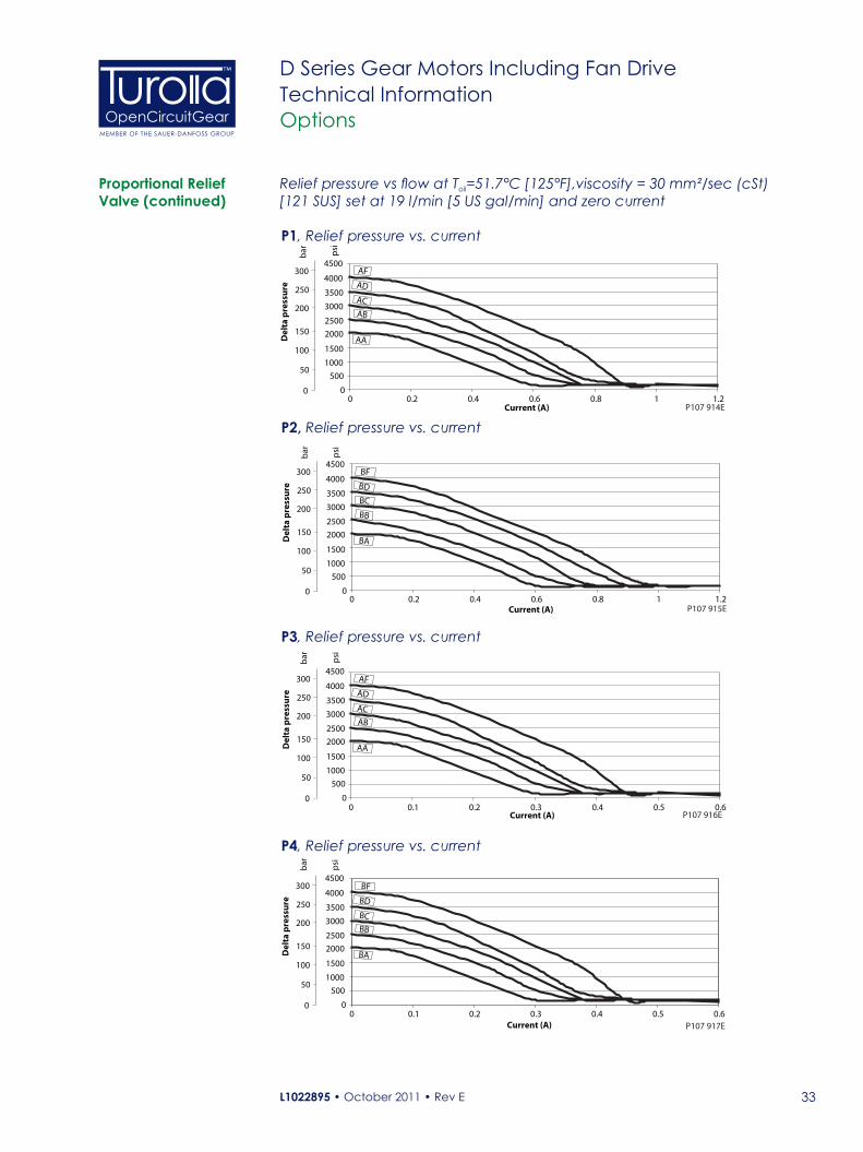
Proportional Relief Valve (continued)
P1, Relief pressure vs. current
P2, Relief pressure vs. current
P3, Relief pressure vs. current
P4, Relief pressure vs. current
Relief pressure vs flow at Toil=51.7°C [125°F],viscosity = 30 mm²/sec (cSt) [121 SUS] set at 19 l/min [5 US gal/min] and zero current
L1022895 • October 2011 • Rev E34
OpenCircuitGearMEMBER OF THE SAUER-DANFOSS GROUP
™ D Series Gear Motors Including Fan DriveTechnical InformationDimension Drawings
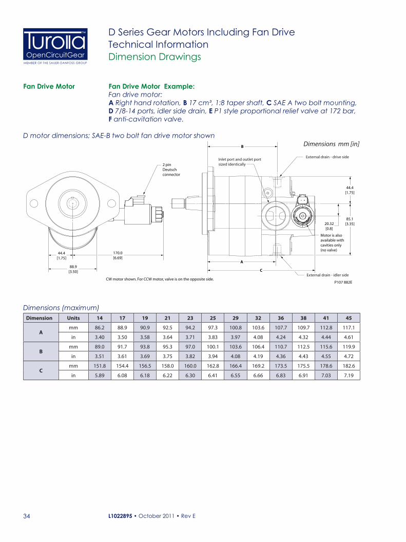
Fan Drive Motor
Dimensions (maximum)Dimension Units 14 17 19 21 23 25 29 32 36 38 41 45
Amm 86.2 88.9 90.9 92.5 94.2 97.3 100.8 103.6 107.7 109.7 112.8 117.1
in 3.40 3.50 3.58 3.64 3.71 3.83 3.97 4.08 4.24 4.32 4.44 4.61
Bmm 89.0 91.7 93.8 95.3 97.0 100.1 103.6 106.4 110.7 112.5 115.6 119.9
in 3.51 3.61 3.69 3.75 3.82 3.94 4.08 4.19 4.36 4.43 4.55 4.72
Cmm 151.8 154.4 156.5 158.0 160.0 162.8 166.4 169.2 173.5 175.5 178.6 182.6
in 5.89 6.08 6.18 6.22 6.30 6.41 6.55 6.66 6.83 6.91 7.03 7.19
D motor dimensions; SAE-B two bolt fan drive motor shown
P107 882ECW motor shown. For CCW motor, valve is on the opposite side.
B
44.4[1.75]
85.1[3.35]
A
C
Motor is alsoavailable withcavities only (no valve)
20.32[0.8]
170.0[6.69]
2 pin Deutsch connector
88.9[3.50]
44.4[1.75]
External drain - drive side Inlet port and outlet portsized identically
External drain - idler side
Dimensions mm [in]
Fan Drive Motor Example:Fan drive motor:A Right hand rotation, B 17 cm³, 1:8 taper shaft, C SAE A two bolt mounting, D 7/8-14 ports, idler side drain, E P1 style proportional relief valve at 172 bar, F anti-cavitation valve.
L1022895 • October 2011 • Rev E 35
OpenCircuitGearMEMBER OF THE SAUER-DANFOSS GROUP
™ D Series Gear Motors Including Fan DriveTechnical InformationDimension Drawings
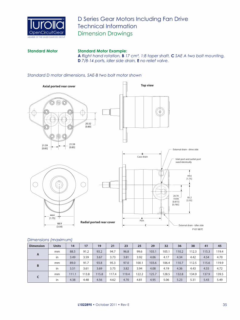
Standard Motor
Dimensions (maximum)Dimension Units 14 17 19 21 23 25 29 32 36 38 41 45
Amm 88.5 91.2 93.2 94.7 96.8 99.6 103.1 105.1 110.2 112.3 115.3 119.4
in 3.49 3.59 3.67 3.73 3.81 3.92 4.06 4.17 4.34 4.42 4.54 4.70
Bmm 89.0 91.7 93.8 95.3 97.0 100.1 103.6 106.4 110.7 112.5 115.6 119.9
in 3.51 3.61 3.69 3.75 3.82 3.94 4.08 4.19 4.36 4.43 4.55 4.72
Cmm 111.1 113.8 115.8 117.4 119.4 122.2 125.7 128.5 132.8 134.9 137.9 139.5
in 4.38 4.48 4.56 4.62 4.70 4.81 4.95 5.06 5.23 5.31 5.43 5.49
Standard D motor dimensions, SAE-B two bolt motor shown
P107 887E
B
A
C
85.2[3.35]
44.6[1.75]
20.7019.94
[0.815][0.785]
88.9[3.50]
44.4[1.75]
20.32[0.80]
21.59[0.85]
Axial ported rear cover Top view
21.59[0.85]
Case drain
Port
External drain - drive side
Inlet port and outlet portsized identically
Radial ported rear cover External drain - idler side
Standard Motor Example:A Right hand rotation, B 17 cm³, 1:8 taper shaft, C SAE A two bolt mounting, D 7/8-14 ports, idler side drain, E no relief valve.

L1022895 • October 2011 • Rev E36
OpenCircuitGearMEMBER OF THE SAUER-DANFOSS GROUP
™ D Series Gear Motors Including Fan DriveTechnical InformationDimension Drawings
Standard Motor with Split Flange Ports
Standard D motor dimensions, SAE-B two bolt motor shown with split flange ports
P107 957E
B
A
C
85.2[3.35]
44.6[1.75]
20.7019.94
[0.815][0.785]
88.9[3.50]
44.4[1.75]
Case drain
Port
External drain - drive side
73.41[2.89]
146.81[5.78]
External drain - idler side
Inlet port and outlet portsized identically
Standard Motor with Split Flange Ports Example: A Right hand rotation, B 17 cm³, 1:8 taper shaft, C SAE A two bolt mounting, D Split flange ports, drive side drain, E No valve.
Dimensions (maximum)Dimension Units 14 17 19 21 23 25 29 32 36 38 41 45
Amm 94.1 96.8 98.8 100.3 102.1 105.2 108.7 111.5 115.8 117.6 120.6 125.0
in 3.71 3.81 3.89 3.95 4.02 4.14 4.28 4.39 4.56 4.63 4.75 4.92
Bmm 89.0 91.7 93.8 95.3 97.0 100.1 103.6 106.4 110.7 112.5 115.6 119.9
in 3.50 3.61 3.69 3.75 3.82 3.94 4.08 4.19 4.36 4.43 4.55 4.72
Cmm 126.1 128.8 130.8 132.3 134.4 137.2 140.7 143.5 147.8 149.9 152.9 157.0
in 4.97 5.07 5.15 5.21 5.29 5.40 5.54 5.65 5.82 5.90 6.02 6.18
L1022895 • October 2011 • Rev E 37
OpenCircuitGearMEMBER OF THE SAUER-DANFOSS GROUP
™ D Series Gear Motors Including Fan DriveTechnical InformationDimension Drawings
P108 246E
2 pinDeutsch
connector
2 pinDeutsch
connector
44.4[1.75]
88.9[3.50]
73.4[2.89]
166.4[6.55]
119.7[4.71]
146.8[5.78]
External drain - idler side
BOutlet port(Near side)
D
A
CExternal drain - drive side
60.3[2.38]
Inlet port(Far side)
Case drainInlet port and outlet port
sized identically(Split �ange ports shown)
20.7019.94
[0.815][0.785]
118.8[4.68]
Counterclockwise rotation
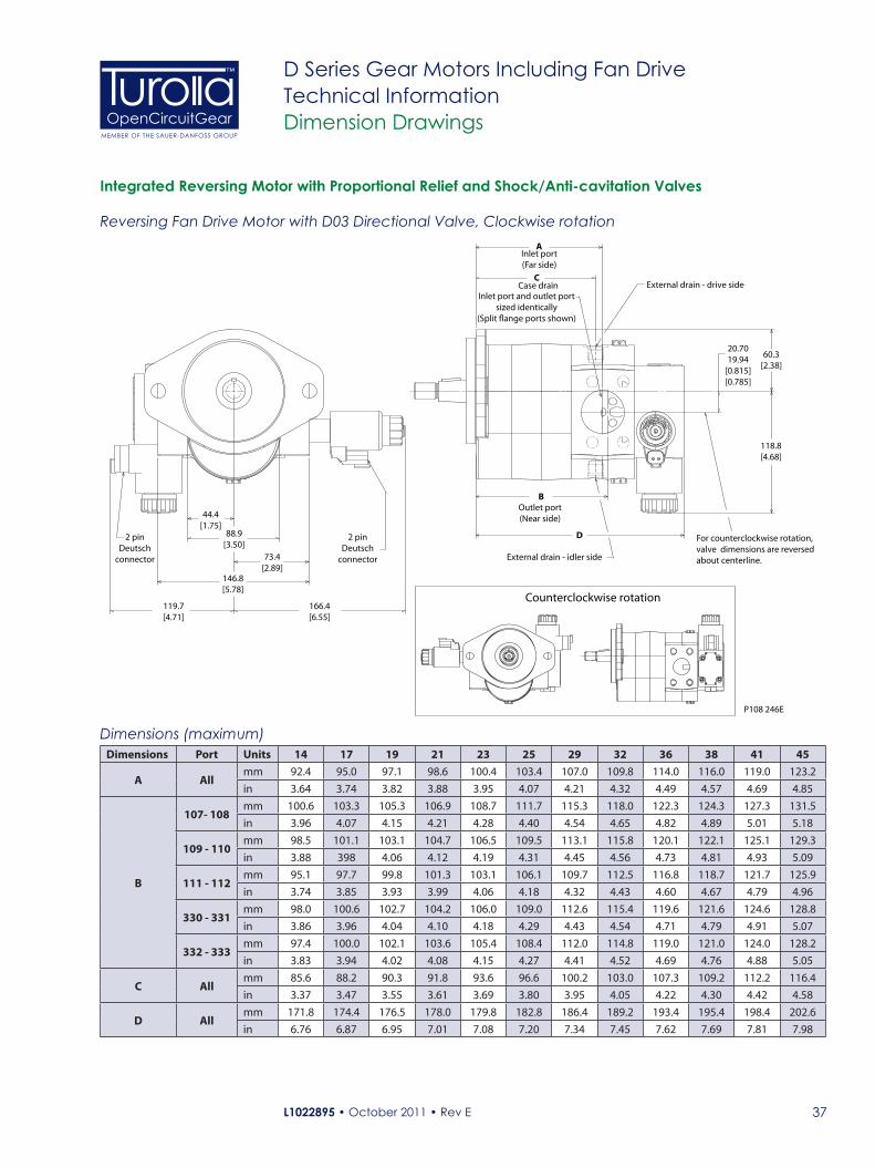
For counterclockwise rotation, valve dimensions are reversed about centerline.
Integrated Reversing Motor with Proportional Relief and Shock/Anti-cavitation Valves
Reversing Fan Drive Motor with D03 Directional Valve, Clockwise rotation
Dimensions (maximum)Dimensions Port Units 14 17 19 21 23 25 29 32 36 38 41 45
A Allmm 92.4 95.0 97.1 98.6 100.4 103.4 107.0 109.8 114.0 116.0 119.0 123.2in 3.64 3.74 3.82 3.88 3.95 4.07 4.21 4.32 4.49 4.57 4.69 4.85
B
107- 108mm 100.6 103.3 105.3 106.9 108.7 111.7 115.3 118.0 122.3 124.3 127.3 131.5in 3.96 4.07 4.15 4.21 4.28 4.40 4.54 4.65 4.82 4.89 5.01 5.18
109 - 110mm 98.5 101.1 103.1 104.7 106.5 109.5 113.1 115.8 120.1 122.1 125.1 129.3in 3.88 398 4.06 4.12 4.19 4.31 4.45 4.56 4.73 4.81 4.93 5.09
111 - 112mm 95.1 97.7 99.8 101.3 103.1 106.1 109.7 112.5 116.8 118.7 121.7 125.9in 3.74 3.85 3.93 3.99 4.06 4.18 4.32 4.43 4.60 4.67 4.79 4.96
330 - 331mm 98.0 100.6 102.7 104.2 106.0 109.0 112.6 115.4 119.6 121.6 124.6 128.8in 3.86 3.96 4.04 4.10 4.18 4.29 4.43 4.54 4.71 4.79 4.91 5.07
332 - 333mm 97.4 100.0 102.1 103.6 105.4 108.4 112.0 114.8 119.0 121.0 124.0 128.2in 3.83 3.94 4.02 4.08 4.15 4.27 4.41 4.52 4.69 4.76 4.88 5.05
C Allmm 85.6 88.2 90.3 91.8 93.6 96.6 100.2 103.0 107.3 109.2 112.2 116.4in 3.37 3.47 3.55 3.61 3.69 3.80 3.95 4.05 4.22 4.30 4.42 4.58
D Allmm 171.8 174.4 176.5 178.0 179.8 182.8 186.4 189.2 193.4 195.4 198.4 202.6in 6.76 6.87 6.95 7.01 7.08 7.20 7.34 7.45 7.62 7.69 7.81 7.98
L1022895 • October 2011 • Rev E38
OpenCircuitGearMEMBER OF THE SAUER-DANFOSS GROUP
™ D Series Gear Motors Including Fan DriveTechnical InformationDimension Drawings
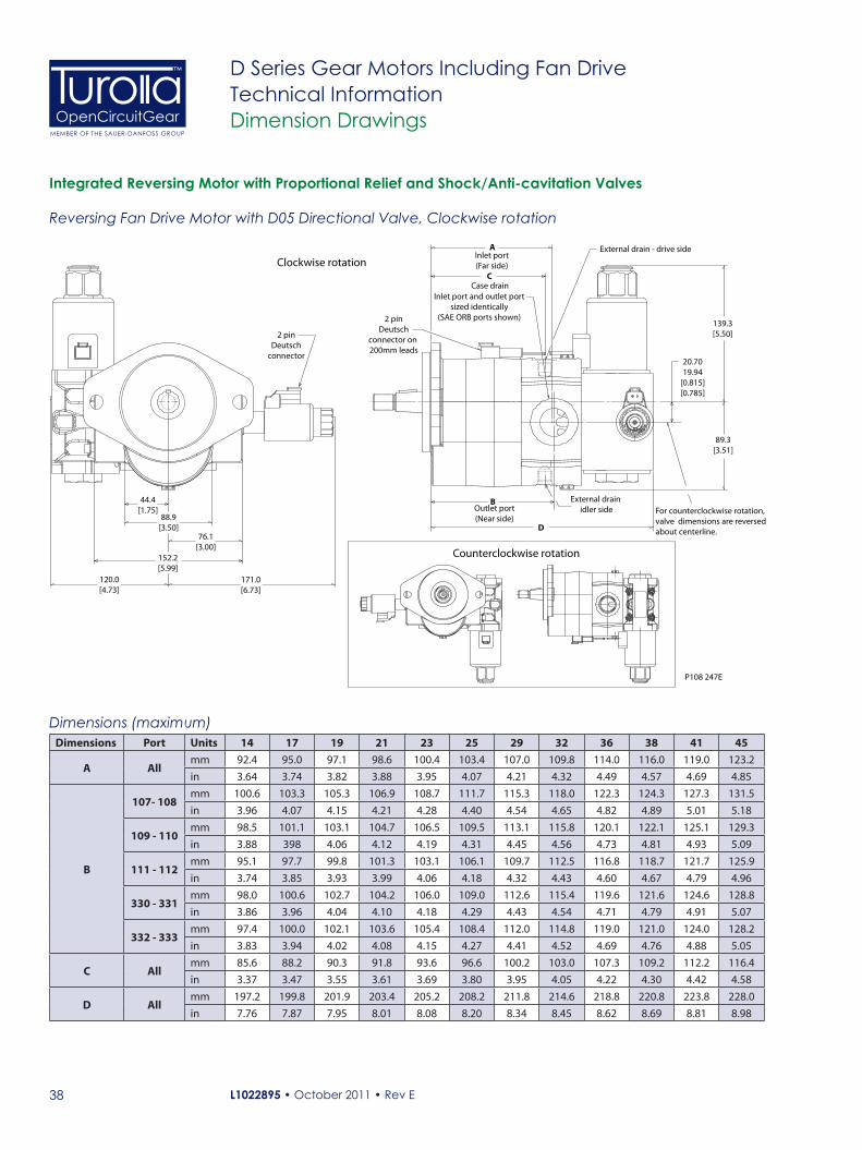
Integrated Reversing Motor with Proportional Relief and Shock/Anti-cavitation Valves
Reversing Fan Drive Motor with D05 Directional Valve, Clockwise rotation
Dimensions (maximum)Dimensions Port Units 14 17 19 21 23 25 29 32 36 38 41 45
A Allmm 92.4 95.0 97.1 98.6 100.4 103.4 107.0 109.8 114.0 116.0 119.0 123.2
in 3.64 3.74 3.82 3.88 3.95 4.07 4.21 4.32 4.49 4.57 4.69 4.85
B
107- 108mm 100.6 103.3 105.3 106.9 108.7 111.7 115.3 118.0 122.3 124.3 127.3 131.5
in 3.96 4.07 4.15 4.21 4.28 4.40 4.54 4.65 4.82 4.89 5.01 5.18
109 - 110mm 98.5 101.1 103.1 104.7 106.5 109.5 113.1 115.8 120.1 122.1 125.1 129.3
in 3.88 398 4.06 4.12 4.19 4.31 4.45 4.56 4.73 4.81 4.93 5.09
111 - 112mm 95.1 97.7 99.8 101.3 103.1 106.1 109.7 112.5 116.8 118.7 121.7 125.9
in 3.74 3.85 3.93 3.99 4.06 4.18 4.32 4.43 4.60 4.67 4.79 4.96
330 - 331mm 98.0 100.6 102.7 104.2 106.0 109.0 112.6 115.4 119.6 121.6 124.6 128.8
in 3.86 3.96 4.04 4.10 4.18 4.29 4.43 4.54 4.71 4.79 4.91 5.07
332 - 333mm 97.4 100.0 102.1 103.6 105.4 108.4 112.0 114.8 119.0 121.0 124.0 128.2
in 3.83 3.94 4.02 4.08 4.15 4.27 4.41 4.52 4.69 4.76 4.88 5.05
C Allmm 85.6 88.2 90.3 91.8 93.6 96.6 100.2 103.0 107.3 109.2 112.2 116.4
in 3.37 3.47 3.55 3.61 3.69 3.80 3.95 4.05 4.22 4.30 4.42 4.58
D Allmm 197.2 199.8 201.9 203.4 205.2 208.2 211.8 214.6 218.8 220.8 223.8 228.0
in 7.76 7.87 7.95 8.01 8.08 8.20 8.34 8.45 8.62 8.69 8.81 8.98
P108 247E
2 pinDeutsch
connector
44.4[1.75]
88.9[3.50]
76.1[3.00]
171.0[6.73]
120.0[4.73]
152.2[5.99]
External drain idler side
BOutlet port(Near side)
D
A
C
External drain - drive side
139.3[5.50]
Inlet port(Far side)
Case drainInlet port and outlet port
sized identically(SAE ORB ports shown)
20.7019.94
[0.815][0.785]
89.3[3.51]
2 pinDeutsch
connector on 200mm leads
Clockwise rotation
Counterclockwise rotation
For counterclockwise rotation, valve dimensions are reversed about centerline.
L1022895 • October 2011 • Rev E 39
OpenCircuitGearMEMBER OF THE SAUER-DANFOSS GROUP
™ D Series Gear Motors Including Fan DriveTechnical InformationPerformance Data
Speed (rpm)
103 bar [1500 PSI]
276 bar [4000 PSI]
276 bar [4000PSI]
172 bar [2500 PSI]
103 bar [1500 PSI]
10
20
30
40
50
60
70
80
500 1000 1500 2000 2500 3000 3500 4000Fl
ow10
20
30
40
50
60
70
Torq
ue
P107 893E
N•m lbf•ftl/minUS gal/min
3
6
10
20
30
40
50
9
12
15
18
20
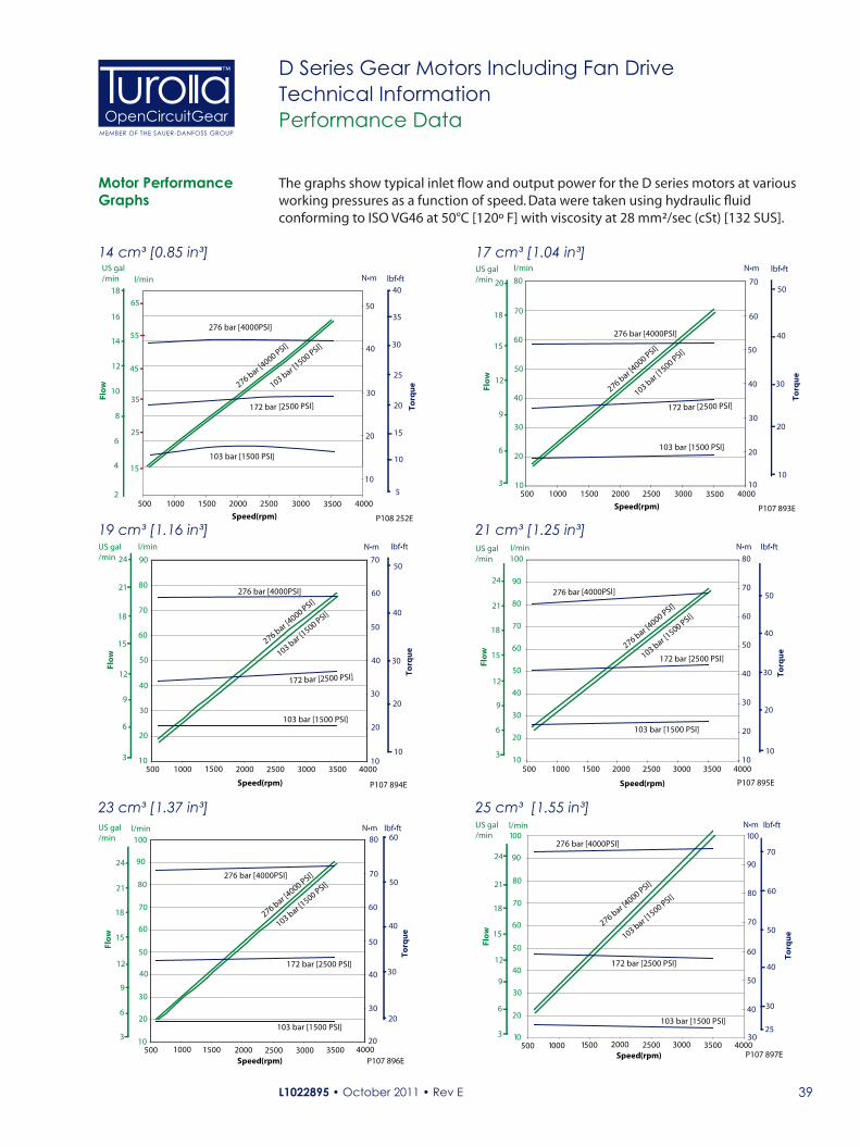
The graphs show typical inlet flow and output power for the D series motors at various working pressures as a function of speed. Data were taken using hydraulic fluid conforming to ISO VG46 at 50°C [120º F] with viscosity at 28 mm²/sec (cSt) [132 SUS].
103 bar [1500 PSI]
276 bar [4000 PSI]
276 bar [4000PSI]
172 bar [2500 PSI]
103 bar [1500 PSI]
10
20
30
40
50
60
70
80
90
500 1000 1500 2000 2500 3000 3500 400010
20
30
40
50
60
70
P107 894ESpeed (rpm)
Flow
N•ml/min
Torq
ue
lbf•ft
10
20
30
40
50
US gal/min
3
6
9
12
15
18
21
24
103 bar [1500 PSI]
276 bar [4000 PSI]276 bar [4000PSI]
172 bar [2500 PSI]
103 bar [1500 PSI]
10
20
30
40
50
60
70
80
90
100
500 1000 1500 2000 2500 3000 3500 400020
30
40
50
60
70
80
P107 896ESpeed (rpm)
N•m
Torq
ue
lbf•ft
20
30
40
50
Flow
US gal/min
3
6
9
12
15
18
21
24
l/min60
103 bar [1500 PSI]
276 bar [4000 PSI]
276 bar [4000PSI]
172 bar [2500 PSI]
103 bar [1500 PSI]
10
20
30
40
50
60
70
80
90
100
500 1000 1500 2000 2500 3000 3500 400010
20
30
40
50
60
70
80
P107 895ESpeed (rpm)
N•m
Torq
ue
lbf•ft
10
20
30
40
50
Flow
US gal/min
3
6
9
12
15
18
21
24
l/min
103 bar [1500 PSI]
276 bar [4000 PSI]
276 bar [4000PSI]
172 bar [2500 PSI]
103 bar [1500 PSI]
10
20
30
40
50
60
70
80
90
100
500 1000 1500 2000 2500 3000 3500 400030
40
50
60
70
80
90
100
P107 897ESpeed (rpm)
N•m
Torq
ue
lbf•ft
30
40
50
Flow
US gal/min
3
6
9
12
15
18
21
24
l/min
60
25
70
25 cm³ [1.55 in³]
21 cm³ [1.25 in³]
23 cm³ [1.37 in³]
17 cm³ [1.04 in³]
19 cm³ [1.16 in³]
Motor Performance Graphs
Speed (rpm)
103 bar [1500 PSI]
276 bar [4000 PSI]
276 bar [4000PSI]
172 bar [2500 PSI]
103 bar [1500 PSI]
500 1000 1500 2000 2500 3000 3500 4000
Flow
10
20
30
40
50
Torq
ue
P108 252E
N•m lbf•ft
10
20
30
40
5
4
6
8
10
12
14
16
18
US gal/min
2
l/min
35
45
55
65
15
25 15
25
35
14 cm³ [0.85 in³]
L1022895 • October 2011 • Rev E40
OpenCircuitGearMEMBER OF THE SAUER-DANFOSS GROUP
™ D Series Gear Motors Including Fan DriveTechnical InformationPerformance Data
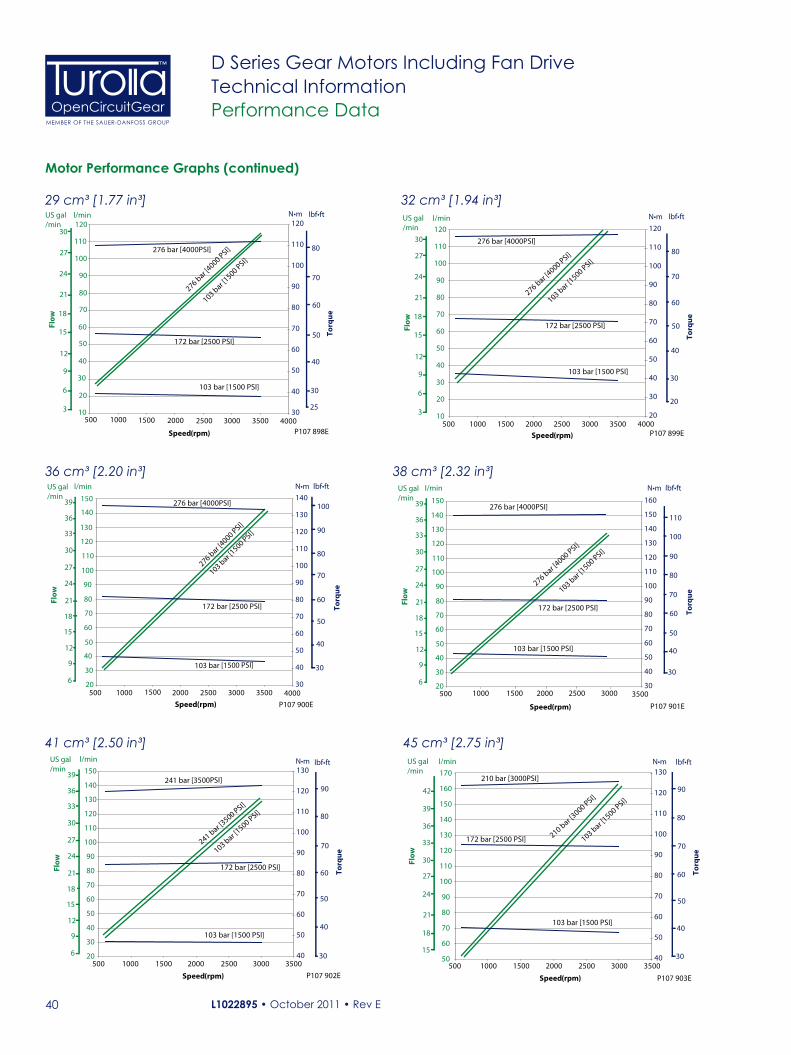
Motor Performance Graphs (continued)
103 bar [1500 PSI]
276 bar [4000 PSI]
276 bar [4000PSI]
172 bar [2500 PSI]
103 bar [1500 PSI]
10
20
30
40
50
60
70
80
90
100
110
120
500 1000 1500 2000 2500 3000 3500 400020
30
40
50
60
70
80
90
100
110
120
P107 899ESpeed (rpm)
N•ml/min
Torq
ue
lbf•ft
30
40
50
60
20
70
80
Flow
US gal/min
3
6
9
12
15
18
21
24
27
30
103 bar [1500 PSI]
276 bar [4000 PSI]
276 bar [4000PSI]
172 bar [2500 PSI]
103 bar [1500 PSI]
20
30
40
50
60
70
80
90
100
110
120
130
140
150
500 1000 1500 2000 2500 3000 3500 400030
40
50
60
70
80
90
100
110
120
130
140
P107 900ESpeed (rpm)
N•ml/min
Torq
ue
lbf•ft
30
40
50
60
70
80
Flow
US gal/min
6
9
12
15
18
21
24
27
30
90
100
33
36
39
103 bar [1500 PSI]
276 bar [4000 PSI]
276 bar [4000PSI]
172 bar [2500 PSI]
103 bar [1500 PSI]
20
30
40
50
60
70
80
90
100
110
120
130
140
150
500 1000 1500 2000 2500 3000 350030
40
50
60
70
80
90
100
110
120
130
140
150
160
P107 901ESpeed (rpm)
N•ml/min
Torq
ue
lbf•ft
30
40
50
60
70
80
Flow
US gal/min
6
9
12
15
18
21
24
27
30 90
10033
36
39
110
103 bar [1500 PSI]
103 bar [1500 PSI]
241 bar [3500 PSI]
241 bar [3500PSI]
172 bar [2500 PSI]
20
30
40
50
60
70
80
90
100
110
120
130
140
150
500 1000 1500 2000 2500 3000 350040
50
60
70
80
90
100
110
120
130
P107 902ESpeed (rpm)
l/min
Flow
US gal/min
6
9
12
15
18
21
24
27
30
33
36
39
N•m
Torq
ue
lbf•ft
30
40
50
60
70
80
90
103 bar [1500 PSI]
210 bar [3000 PSI]
210 bar [3000PSI]
172 bar [2500 PSI]
103 bar [1500 PSI]
50
60
70
80
90
100
110
120
130
140
150
160
170
500 1000 1500 2000 2500 3000 350040
50
60
70
80
90
100
110
120
130
P107 903ESpeed (rpm)
l/min
Flow
US gal/min
15
18
21
24
27
30
33
36
39
N•m
Torq
ue
lbf•ft
30
40
50
60
70
80
9042
32 cm³ [1.94 in³]
36 cm³ [2.20 in³] 38 cm³ [2.32 in³]
41 cm³ [2.50 in³] 45 cm³ [2.75 in³]
103 bar [1500 PSI]
276 bar [4000 PSI]276 bar [4000PSI]
172 bar [2500 PSI]
103 bar [1500 PSI]
10
20
30
40
50
60
70
80
90
100
110
120
500 1000 1500 2000 2500 3000 3500 400030
40
50
60
70
80
90
100
110
120
P107 898ESpeed (rpm)
N•m
Torq
ue
lbf•ft
30
40
50
Flow
US gal/min
3
6
9
12
15
18
21
24
l/min
60
25
70
27 80
30
29 cm³ [1.77 in³]

L1022895 • October 2011 • Rev E 41
OpenCircuitGearMEMBER OF THE SAUER-DANFOSS GROUP
™ D Series Gear Motors Including Fan DriveTechnical InformationReference Literature
TurollaOCG Fan Drive Related Literature
Literature reference - Software Title Type Order numberSX Microcontroller Fan Drive Personality Technical Information 11023458
Literature reference - Fan Drive ControlsTitle Type Order numberFan Drive Control Technical Information 11005336Fan Drive Control Assembly Technical Information 11005337Fan Drive Control Temperature Sensors Technical Information BLN-95-9063PLUS+1 compliant Heavy-Duty Pressure Transmitter Datasheet 520L0801PLUS+1 compliant Heavy-Duty Pressure Transmitter - SAE Thread Version
Datasheet 11005336
PLUS+1 MC088 015-00000-Controller Datasheet 11006645
Literature reference - ValvesTitle Type Order numberModulating and Reversing Fan Drive HICs Datasheet L1001666Cartridge Valves Technical Information 520L0588
Literature reference - Pumps and MotorsTitle Type Order numberSeries D Hydraulic Gear Pumps Technical Information L1022940Group 2 Gear Pumps Technical Information L1016341Group 3 Gear Pumps Technical Information L1016456Group 1, 2 and 3 Gear Motors Technical Information L1016082SGM2, SGM3 Fan Drive Gear Motors Technical Information L1016036SGM2 Fan Drive Gear Motors Datasheet 11029652SGM3 Fan Drive Gear Motors Datasheet 11056719Series 45 Open Circuit Pumps Technical Information 520L0519
Literature reference - Fluids Title Type Order numberHydraulic Fluids and Lubricants Technical Information L1021414
L1022895 • October 2011 • Rev E42
OpenCircuitGearMEMBER OF THE SAUER-DANFOSS GROUP
™ D Series Gear Motors Including Fan DriveTechnical InformationNotes

L1022895 • October 2011 • Rev E 43
OpenCircuitGearMEMBER OF THE SAUER-DANFOSS GROUP
™ D Series Gear Motors Including Fan DriveTechnical InformationNotes

L1022895 • October 2011 • Rev E
Our Products
Aluminum Gear Pumps
Aluminum Gear Motors
Cast Iron Gear Pumps
Cast Iron Gear Motors
Fan Drive Gear Motors Aluminum
Fan Drive Gear Motors Cast Iron
Local address: TurollaOCGVia Villanova 28 40050 Villanova di CastenasoBologna, ItalyPhone: +39 051 6054411Fax: +39 051 6053033
TurollaOCGKukučínova 2148-8401701 Považská Bystrica, SlovakiaPhone: +421 424 301 544Fax: +421 424 301 626
TurollaOCG2800 East 13th StreetAmes, IA 50010 USAPhone: +1 515 239 6000Fax: +1 515 239 6618
OpenCircuitGearMEMBER OF THE SAUER-DANFOSS GROUP
™
Turolla OpenCircuitGear™ TurollaOCG, with more than 60 years of experience in designing and manufacturing gear pumps, gear motors and fan drive motors of superior quality, is the ideal partner ensuring robustness and reliability to your work functions.
We are fast and responsive - the � rst to specify a customer product, the most experienced in providing technical knowledge and support for fan drive solutions.
We o� er a lean value chain to our partners and customers and the shortest lead time in the market.
TurollaOCG is member of the Sauer-Danfoss Group.
www.turollaocg.com