Gear Motors Group 1, 2 and 3 OpenCircuitGear _engrenages/... · 2 OpenCircuitGear MEMBER OF THE...
30
OpenCircuitGear MEMBER OF THE SAUER-DANFOSS GROUP ™ Gear Motors Group 1, 2 and 3 Technical Information
Transcript of Gear Motors Group 1, 2 and 3 OpenCircuitGear _engrenages/... · 2 OpenCircuitGear MEMBER OF THE...

OpenCircuitGearMEMBER OF THE SAUER-DANFOSS GROUP
™Gear MotorsGroup 1, 2 and 3
Technical Information

2
OpenCircuitGearMEMBER OF THE SAUER-DANFOSS GROUP
™
L1016082 • June 2010 • Rev A
Overview The Turolla OCG Gear Motors is a range of peak performance fixed displacement hydraulic motors available in three different frame sizes: Group 1, Group 2 and Group 3, all as uni- and bidirectional version.
Constructed of a high strength extruded aluminum body with aluminum rear cover and aluminum front flange, all motors are balanced for exceptional efficiency and designed to ensure an excellent starting torque and, in the bidirectional version, to guarantee the ability to work with high back pressure and extremely low system pressure.
The flexibility of the range in each frame size combined with the high efficiency and low starting torque makes the Turolla OCG Gear Motors ideal for a wide range of applications sectors including on- and off-highway hydraulic fan drive systems, turf care, road bildge, fork lifts and municipal.
All the unidirectional motors have the same construction of the correspondent pump as well but, with inlet and outlet positioned at the opposite side for the same rotation.
Some representatives of gear motors: SKM1NN 06SA SNM3NN 01BA SNM3NL 07SA
General Information
F005 219 F005 105
F005 216 F005 217
SNM2NN 9JDB SNU2NN 06GA
F005 220
F005 221
Gear Motors • Group 1, 2 and 3Technical Information
SNU2NN 06SA
Front cover illustrations: F005 214, F005 219, F005 221, F005 217, F005 071, F005 216, F005 028, F005 220, F301338 and P005 256..
© 2010 Turolla OpenCircuitGear™. All rights reserved.
Turolla OCG accepts no responsibility for possible errors in catalogs, brochures and other printed material. Turolla OCG reserves the right to alter its products without prior notice. This also applies to products already ordered provided that such alterations can be made without affecting agreed specifi cations. All trademarks in this material are properties of their respective owners. Sauer-Danfoss, Turolla, Turolla OpenCircuitGear, Turolla OCG, OpenCircuitGear, Fast Lane and PLUS+1 are trademarks of the Sauer-Danfoss Group.

3
OpenCircuitGearMEMBER OF THE SAUER-DANFOSS GROUP
™
L1016082 • June 2010 • Rev A
Contents
Gear Motors • Group 1, 2 and 3Technical Information
General Information
System Requirements
Group 1 General Information
Product Ordering
Motor Performance
Product Options
Dimensions
Group 2 General Information
Product Ordering
Motor Performance
Overview ........................................................................................................................................................... 2Features and benefits ................................................................................................................................... 5Motor displacements .................................................................................................................................... 5Determination of nominal motor sizes .................................................................................................. 6
Based on SI units/Based on US units .................................................................................................. 6
Pressure .............................................................................................................................................................. 7Speed .................................................................................................................................................................. 7Hydraulic fluids ............................................................................................................................................... 8Temperature and viscosity .......................................................................................................................... 8Filtration............................................................................................................................................................. 9Reservoir ............................................................................................................................................................ 9
Filters ............................................................................................................................................................. 9Selecting a filter ......................................................................................................................................... 9
Line sizing .......................................................................................................................................................10Motor shaft connection .............................................................................................................................10Motor shaft load data form .......................................................................................................................11Motor life .........................................................................................................................................................12
Motor design ..................................................................................................................................................13SKM1NN .....................................................................................................................................................13SKU1NN .....................................................................................................................................................13SNU1NN......................................................................................................................................................13
Technical data ................................................................................................................................................14
Model code .....................................................................................................................................................15
Motor performance graphs ......................................................................................................................17
Flange, shaft and port configurations ..................................................................................................19Mounting flanges options .........................................................................................................................20Shaft options ..................................................................................................................................................20Port configurations ......................................................................................................................................21Bidirectional motor ports ..........................................................................................................................22Unidirectional motor ports .......................................................................................................................22
SKM1NN, SKU1NN, SNU1NN – 01BA .....................................................................................................23SKM1NN, SKU1NN – 02BB, 02FA .............................................................................................................24SKM1NN, SKU1NN – 06GA and 06SA ....................................................................................................25
Motor design ..................................................................................................................................................26SNM2NN .....................................................................................................................................................26SNU2NN......................................................................................................................................................26SKU2NN ......................................................................................................................................................26
Technical data ................................................................................................................................................27
Model code .....................................................................................................................................................28
Motor performance graphs ......................................................................................................................31
4
OpenCircuitGearMEMBER OF THE SAUER-DANFOSS GROUP
™
L1016082 • June 2010 • Rev A
Contents
Product Options
Dimensions
Group 3 General Information
Product Ordering
Motor Performance
Product Options
Dimensions
Gear Motors • Group 1, 2 and 3Technical Information
Flange, shaft and port configurations ..................................................................................................33Mounting flanges options .........................................................................................................................34Shaft options ..................................................................................................................................................34Port configurations ......................................................................................................................................35Bidirectional motor ports .........................................................................................................................36Unidirectional motor ports .......................................................................................................................36Integral relief valve – SNM2IN ..................................................................................................................37
Variant codes for ordering integral relief valve ............................................................................37Integral relief valve and Anti-cavitation check valve – SNM2JN .................................................38Outrigger bearing assembly – SNM2NN ..............................................................................................39
Dimensions ...............................................................................................................................................41
SNM2NN, SNU2NN – 01DA, 01FA and 01BA .......................................................................................43SNM2NN, SNU2NN – 02DB and 02AA ...................................................................................................44SNM2NN, SNU2NN – 03CA........................................................................................................................45SNM2NN, SNU2NN–04DB/05DB and 04AA/05AA ............................................................................46SNM2NN, SNU2NN, SKU2NN – 06SA, 06GA ........................................................................................47
Motor design ..................................................................................................................................................48SNM3NN .....................................................................................................................................................48SNU3NN......................................................................................................................................................48
Technical data ................................................................................................................................................49
Model code .....................................................................................................................................................50
Motor performance graphs ......................................................................................................................53
Flange, shaft and port configurations ..................................................................................................56Shaft and flange availability ....................................................................................................................57
Shaft and flange availability and torque capability ....................................................................57Bidirectional motor ports .........................................................................................................................58Unidirectional motor ports .......................................................................................................................59
SNM3NN, SNU3NN – 01FA, 01DA and 01BA .......................................................................................62SNM3NN, SNU3NN – 02FA, 02DB and 02AA .......................................................................................63SNM3NN, SNU3NN – 03FB and 03BB ....................................................................................................64SNM3NN, SNU3NN – 06AA .......................................................................................................................65SNM3NN, SNU3NN – 07BC, 07SA and 07GA .......................................................................................66
5
OpenCircuitGearMEMBER OF THE SAUER-DANFOSS GROUP
™
L1016082 • June 2010 • Rev A
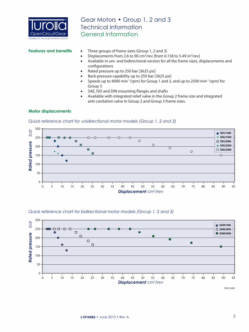
Motor displacements
General Information
Gear Motors • Group 1, 2 and 3Technical Information
Features and benefits • Three groups of frame sizes (Group 1, 2 and 3) • Displacements from 2.6 to 90 cm3/rev [from 0.158 to 5.49 in3/rev]• Available in uni- and bidirectional version for all the frame sizes, displacements and
configurations• Rated pressure up to 250 bar [3625 psi] • Back pressure capability up to 250 bar [3625 psi] • Speeds up to 4000 min-1 (rpm) for Group 1 and 2, and up to 2500 min-1 (rpm) for
Group 3• SAE, ISO and DIN mounting flanges and shafts • Available with integrated relief valve in the Group 2 frame size and integrated
anti-cavitation valve in Group 2 and Group 3 frame sizes.
300
250
200
150
100
50
00 5 10 15 20 25 30 35 40 45 50 55 60 65 70 75 80 85 90 95
Displacement cm3/rev
SKU1NNSNU1NNSKU2NNSNU2NNSNU3NN
Rate
d pr
essu
re
bar
P005 400E
300
250
200
150
100
50
00 5 10 15 20 25 30 35 40 45 50 55 60 65 70 75 80 85 90 95
Displacement cm3/rev
SKM1NNSNM2NNSNM3NN
Rate
d pr
essu
re
bar
Quick reference chart for unidirectional motor models (Group 1, 2 and 3)
Quick reference chart for bidirectional motor models (Group 1, 2 and 3)
6
OpenCircuitGearMEMBER OF THE SAUER-DANFOSS GROUP
™
L1016082 • June 2010 • Rev A
General Information
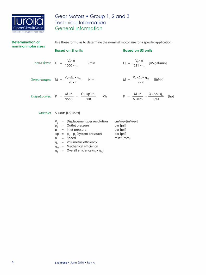
Use these formulas to determine the nominal motor size for a specific application.Determination of nominal motor sizes
Based on SI units Based on US units
Vg • n Q = l/min 1000 • ηv
Vg • ∆p • ηmM = N•m 20 • π
M • n Q • ∆p • ηtP = = kW 9550 600
SI units [US units]
Vg = Displacement per revolution cm3/rev [in3/rev]po = Outlet pressure bar [psi]pi = Inlet pressure bar [psi]∆p = po – pi (system pressure) bar [psi]n = Speed min-1 (rpm)ηv = Volumetric efficiencyηm = Mechanical efficiencyηt = Overall efficiency (ηv • ηm)
Vg • nQ = [US gal/min] 231 • ηv
Vg • ∆p • ηmM = [lbf•in] 2 • π
M • n Q • ∆p • ηtP = = [hp] 63 025 1714
Input flow:
Output torque:
Output power:
Variables
Gear Motors • Group 1, 2 and 3Technical Information

7
OpenCircuitGearMEMBER OF THE SAUER-DANFOSS GROUP
™
L1016082 • June 2010 • Rev A
Pressure
Speed
System Requirements
Peak pressure is the highest intermittent pressure allowed. The relief valve overshoot (reaction time) determines peak pressure. It is assumed to occur for less than 100 ms. The illustration to the right shows peak pressure in relation to rated pressure and reaction time (100 ms maximum).
Rated pressure is the average, regularly occurring operating inlet pressure that should yield satisfactory product life. The maximum machine load at the motor shaft determines rated pressure.
Maximum speed is the limit recommended by Turolla OCG for a particular gear motor when operating at rated pressure. It is the highest speed at which normal life can be expected.
The lower limit of operating speed is the minimum speed. It is the lowest speed at which normal life can be expected. The minimum speed increases as operating system pressure increases. When operating under higher pressures, a higher minimum speed must be maintained, as illustrated to the right.
Rated
P1
Pres
sure
0N MaxN2
P101 548E
Operatingenvelope
1
Speed
Peak pressure
Rated pressure
Reaction time (100 ms max)
TimeP005 006E
Pres
sure
Time versus pressure
Speed versus pressure
System pressure is the differential between the inlet and outlet ports. It is a dominant operating variable affecting hydraulic unit life. High system pressure, resulting from high load at the motor shaft, reduces expected life. System pressure must remain at, or below, rated pressure during normal operation to achieve expected life.
Back pressure is the average, regularly occurring operating outlet pressure that should yield satisfactory bidirectional motor life. The hydraulic load demand downstream of the motor determines the back pressure. Unidirectional motors cannot work with back pressure and the maximum back pressure allowed is 5 bar [72 psi] rated and 7 bar [101 psi ] as peak.
Case Drain Pressure is the regularly occurring case drain line pressure that should yield satisfactory bidirectional motor life. It is recommended to design the case drain piping connecting the case drain direct to the tank in order to keep the case drain pressure as low as possible. The max continuous case drain pressure allowed is 5 bar [72 psi] rated and 7 bar [101 psi] as peak.
Gear Motors • Group 1, 2 and 3Technical Information
N1 = minimum speed at low pressureN2 = minimum speed at rated pressure
P101 548E

8
OpenCircuitGearMEMBER OF THE SAUER-DANFOSS GROUP
™
L1016082 • June 2010 • Rev A
Temperature and viscosity requirements must be concurrently satisfied. Use petroleum/mineral-based fluids.
High temperature limits apply at the inlet port of the motor. The motor should run at or below the maximum continuous temperature. The peak temperature is based on material properties. Don’t exceed it.
Cold oil, generally, doesn’t affect the durability of motor components. It may affect the ability of oil to flow and transmit power. For this reason, keep the temperature at 16°C [60 °F] above the pour point of the hydraulic fluid.
Minimum (cold start) temperature relates to the physical properties of component materials.
Minimum viscosity occurs only during brief occasions of maximum ambient temperature and severe duty cycle operation. You will encounter maximum viscosity only at cold start. During this condition, limit speeds until the system warms up. Size heat exchangers to keep the fluid within these limits. Test regularly to verify that these temperatures and viscosity limits aren’t exceeded. For maximum unit efficiency and bearing life, keep the fluid viscosity in the recommended viscosity range.
System Requirements
Hydraulic fluids
Temperature and viscosity
TemperatureMinimum (cold start)
°C[°F]
-20 [-4]Maximum continuous 80 [176]Peak (intermittent) 90 [194]
Fluid viscosityMaximum (cold start)
mm2/s[SUS]
1000 [4600]Recommended range 12-60 [66-290]Minimum 10 [60]
Ratings and data for gear motors are based on operating with premium hydraulic fluids containing oxidation, rust, and foam inhibitors. These fluids must possess good thermal and hydrolytic stability to prevent wear, erosion, and corrosion of internal components. They include:• Hydraulic fluids following DIN 51524, part 2 (HLP) and part 3 (HVLP) specifications• API CD engine oils conforming to SAE J183• M2C33F or G automatic transmission fluids• Certain agricultural tractor fluids
Use only clean fluid in the motor and hydraulic circuit.
C CautionNever mix hydraulic fluids.
Please see Turolla OCG publication Hydraulic Fluids and Lubricants Technical Information, 520L0463 for more information. Refer to publication Experience with Biodegradable Hydraulic Fluids Technical Information, 520L0465 for information relating to biodegradable fluids.
Gear Motors • Group 1, 2 and 3Technical Information

9
OpenCircuitGearMEMBER OF THE SAUER-DANFOSS GROUP
™
L1016082 • June 2010 • Rev A
FiltersUse a filter that conforms to Class 22/18/13 of ISO 4406 (or better). It may be on the motor outlet (discharge filtration) or inlet (pressure filtration).
Selecting a filterWhen selecting a filter, please consider:• contaminant ingression rate (determined by factors such as the number of actuators
used in the system)• generation of contaminants in the system• required fluid cleanliness• desired maintenance interval• filtration requirements of other system components
Measure filter efficiency with a Beta ratio (βX):• for discharge filtration with controlled reservoir ingression, use a β35-45 = 75 filter• for pressure filtration, use a filtration with an efficiency of β10 = 75
βx ratio is a measure of filter efficiency defined by ISO 4572. It is the ratio of the number of particles greater than a given diameter ( “X“ in microns) upstream of the filter to the number of these particles downstream of the filter.
Fluid cleanliness level and βx ratioFluid cleanliness level (per ISO 4406) Class 22/18/13 or betterβx ratio (discharge filtration) β35-45 = 75 and β10 = 2
βx ratio (pressure filtration) β10 = 75
Recommended inlet screen size 100 – 125 µm [0.0039 – 0.0049 in]
The filtration requirements for each system are unique. Evaluate filtration system capacity by monitoring and testing prototypes.
The reservoir provides clean fluid, dissipates heat, removes entrained air, and allows for fluid volume changes associated with fluid expansion and during all system operating modes. A correctly sized reservoir accommodates maximum volume changes during all system operating modes. It promotes deaeration of the fluid as it passes through, and accommodates a fluid dwell-time between 60 and 180 seconds, allowing entrained air to escape.
Minimum reservoir capacity depends on the volume required to cool and hold the oil, allowing for expansion due to temperature changes. A fluid volume of one to three times the motor output flow (per minute) is satisfactory. The minimum reservoir capacity is 125% of the fluid volume.
Put the return-line below the lowest expected fluid level to allow discharge into the reservoir for maximum dwell and efficient deaeration. A baffle (or baffles) between the return and suction lines promotes deaeration and reduces fluid surges.
Reservoir
Filtration
System Requirements
Gear Motors • Group 1, 2 and 3Technical Information

10
OpenCircuitGearMEMBER OF THE SAUER-DANFOSS GROUP
™
L1016082 • June 2010 • Rev A
System Requirements
Line sizing
Motor shaft connectionPilot cavity
Ø 0.1 [0.004]
P101 002E
Mating spline
Shaft options for gear motors include tapered, splined, parallel or Turolla OCG tang shafts.
Plug-in drives, with a splined shaft, can impose severe radial loads when the mating spline is rigidly supported. Increasing spline clearance does not alleviate this condition.
Use plug-in drives if the concentricity between the mating spline and pilot diameter is within 0.1 mm [0.004 in]. Lubricate the drive by flooding it with oil. A three-piece coupling minimizes radial or thrust shaft loads.
Choose pipe sizes that accommodate minimum fluid velocity to reduce system noise, pressure drops, and overheating. This maximizes system life and performance. The line velocity should not exceed the values in this table:
Maximum line velocityInlet
m/s [ft/sec]2.5 [8.2]
Outlet 5.0 [16.4]Return 3.0 [9.8]
Most systems use hydraulic oil containing 10% dissolved air by volume. Over-aeration is the result of the flow-line restrictions. These include inadequate pipe sizes, sharp bends, or elbow fittings, causing a reduction of flow line cross sectional area. This problem will not occur if rated speed requirements are maintained, and reservoir size and location are adequate.
C CautionIn order to avoid spline shaft damages it is recommended to use carburised and hardened steel couplings with 80-82 HRA surface hardness.
Allowable radial shaft loads are a function of the load position, load orientation, and operating pressure of the hydraulic motor. All external shaft loads have an effect on bearing life, and may affect motor performance.
In applications where external shaft loads can not be avoided, minimize the impact on the motor by optimizing the orientation and magnitude of the load. Avoid thrust loads in either direction. Please contact Turolla OCG, if continuously applied external radial or thrust loads occur.
Motor shaft connection
Gear Motors • Group 1, 2 and 3Technical Information
11
OpenCircuitGearMEMBER OF THE SAUER-DANFOSS GROUP
™
L1016082 • June 2010 • Rev A
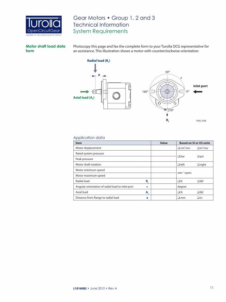
Application dataItem Value Based on SI or US units
Motor displacement cm3/rev in3/rev
Rated system pressure bar psi
Peak pressure
Motor shaft rotation left right
Motor minimum speedmin-1 (rpm)
Motor maximum speed
Radial load RL N lbf
Angular orientation of radial load to inlet port α degree
Axial load AL N lbf
Distance from flange to radial load a mm in
System Requirements
Photocopy this page and fax the complete form to your Turolla OCG representative for an assistance. This illustration shows a motor with counterclockwise orientation:
Motor shaft load data form
P005 259E
a90o
a
0o
270o
180o
Inlet port
Axial load (AL)
Radial load (RL)
RL
Gear Motors • Group 1, 2 and 3Technical Information

12
OpenCircuitGearMEMBER OF THE SAUER-DANFOSS GROUP
™
L1016082 • June 2010 • Rev A
System Requirements
Motor life is a function of speed, system pressure, and other system parameters (such as fluid quality and cleanliness).
All Turolla OCG gear motors use hydrodynamic journal bearings that have an oil film maintained between the gear/shaft and bearing surfaces at all times. If the oil film is sufficiently sustained through proper system maintenance and operating within recommended limits, long life can be expected.
B10 life expectancy number is generally associated with rolling element bearings. It does not exist for hydrodynamic bearings.
High pressure impacts motor life. When submitting an application for review, provide machine duty cycle data that includes percentages of time at various loads and speeds. We strongly recommend a prototype testing program to verify operating parameters and their impact on life expectancy before finalizing any system design.
Motor life
Gear Motors • Group 1, 2 and 3Technical Information
26
OpenCircuitGearMEMBER OF THE SAUER-DANFOSS GROUP
™
L1016082 • June 2010 • Rev A
Gear Motors • Group 2Technical InformationGeneral Information
F005 214
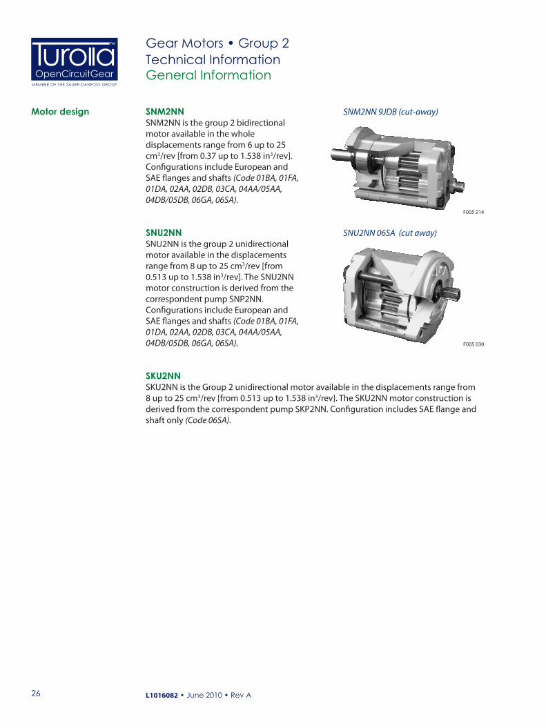
SNM2NN 9JDB (cut-away)Motor design SNM2NNSNM2NN is the group 2 bidirectional motor available in the whole displacements range from 6 up to 25 cm3/rev [from 0.37 up to 1.538 in3/rev]. Configurations include European and SAE flanges and shafts (Code 01BA, 01FA, 01DA, 02AA, 02DB, 03CA, 04AA/05AA, 04DB/05DB, 06GA, 06SA).
SNU2NNSNU2NN is the group 2 unidirectional motor available in the displacements range from 8 up to 25 cm3/rev [from 0.513 up to 1.538 in3/rev]. The SNU2NN motor construction is derived from the correspondent pump SNP2NN. Configurations include European and SAE flanges and shafts (Code 01BA, 01FA, 01DA, 02AA, 02DB, 03CA, 04AA/05AA, 04DB/05DB, 06GA, 06SA).
SNU2NN 06SA (cut away)
F005 030
SKU2NNSKU2NN is the Group 2 unidirectional motor available in the displacements range from 8 up to 25 cm3/rev [from 0.513 up to 1.538 in3/rev]. The SKU2NN motor construction is derived from the correspondent pump SKP2NN. Configuration includes SAE flange and shaft only (Code 06SA).

27
OpenCircuitGearMEMBER OF THE SAUER-DANFOSS GROUP
™
L1016082 • June 2010 • Rev A
Gear Motors • Group 2Technical Information
Technical data
General Information
The table below details the technical data for Group 2 gear motors based on the model and displacement configuration.
Technical data for Group 2 gear motorsFrame size
6,0* 8,0 011 014 017 019 022 025
Displacementcm3/rev[in3/rev]
6.0[0.36]
8.4[0.513]
10.8[0.659]
14.4[0.879]
16.8[1.025]
19.2[1.171]
22.8[1.391]
25.2[1.538]
SNM2NN (bidirectional motor)
Peak pressure
bar [psi]
280[4060]
280[4060]
280[4060]
280[4060]
260[3770]
230[3335]
200[2900]
180[2610]
Rated pressure250
[3625]250
[3625]250
[3625]250
[3625]230
[3335]210
[3045]180
[2610]160
[2320]
Outlet back pressure250
[3625]250
[3625]250
[3625]250
[3625]230
[3335]210
[3045]180
[2610]160
[2320]
Minimum speedmin-1 (rpm)
700 700 700 700 500 500 500 500Maximum speed 4000 4000 4000 4000 4000 3500 3500 3500SNU2NN (unidirectional motor)
Peak pressurebar [psi]
–
280[4060]
280[4060]
280[4060]
260[3770]
230[3335]
200[2900]
180[2610]
Rated pressure250
[3625]250
[3625]250
[3625]230
[3335]210
[3045]180
[2610]160
[2320]Minimum speed
min-1 (rpm)600 600 600 500 500 500 500
Maximum speed 3500 3500 3500 3000 3000 3000 2500
SKU2NN (unidirectional motor)
Peak pressurebar [psi]
–
280[4060]
280[4060]
280[4060]
260[3770]
230[3335]
200[2900]
175[2815]
Rated pressure250
[3625]250
[3625]250
[3625]230
[3335]210
[3045]180
[2610]160
[2320]Minimum speed
min-1 (rpm)600 600 600 500 500 500 500
Maximum speed 3500 3500 3500 3000 3000 3000 2500All (SNM2NN, SNU2NN, SKU2NN)
Weight kg [lb]2.4
[5.3]2.5
[5.5]2.7
[5.5]2.9
[6.3]3.0
[6.5]3.1
[6.7]3.2
[7.0]3.3
[7.3]Moment of inertia ofrotating components
x 10-6 kg•m2
[x 10-6 lb•ft2]26.5[629]
32.4[769]
38.4[911]
47.3[1122]
53.3[1265]
59.2[1405]
68.1[1616]
74.1[1758]
Theoretical flow atmaximum speed
l/min[US gal/min]
24[6.3]
33.6[8.9]
43.2[11.4]
50.4[13.3]
50.4[13.3]
57.6[15.2]
68.4[18.0]
75.6[20.0]
* Before chosing this frame size, please apply to Turolla OCG technical department.
CCautionThe rated and peak pressure mentioned are for motors with flanged ports only. When threaded ports are required a de-rated performance has to be considered. To verify the compliance of an high pressure application with a threaded ports pump apply to a Turolla OCG representative.
1 kg•m2 = 23.68 lb•ft2

28
OpenCircuitGearMEMBER OF THE SAUER-DANFOSS GROUP
™
L1016082 • June 2010 • Rev A
Gear Motors • Group 2Technical Information
Legend:
= Standard
m = Optional
– = Not Available
A B C D E F G H I J K L M N/
A TypeSNM2NN Bidirectional gear motorSHM2NN High pressure bidirectional gear motorSNU2NN Unidirectional gear motorSNM2IN Unidirectional gear motor with integrated relief valve (internal drain)SNM2GN Unidirectional gear motor with anti-cavitation check valveSNM2JN Unidirectional gear motor with integrated relief valve and anti-cavitation check valve
B Displacement 6,0 6.0 cm3/rev [0.360 in3/rev]8,0 8.4 cm3/rev [0.513 in3/rev]011 10.8 cm3/rev [0.659 in3/rev]014 14.4 cm3/rev [0.879 in3/rev]017 16.8 cm3/rev [1.025 in3/rev]019 19.2 cm3/rev [1.171 in3/rev]022 22.8 cm3/rev [1.391 in3/rev]025 25.2 cm3/rev [1.538 in3/rev]
Product Ordering
Model code
C Direction of rotationR Right hand (clockwise)L Left hand (counterclockwise)B Bidirectional
D Version N Standard version
E Mounting flange and shaft
Code DescriptionSN
M2N
N
SHM
2NN
SNU
2NN
SNM
2IN
SNM
2GN
SNM
2JN
01BA European 4-bolt flange 01 • Tapered shaft 1:8 – –
01FA European 4-bolt flange 01 • Parallel shaft 15mm [0.591 in] – – – –
01DA European 4-bolt flange 01 • DIN splined shaft – – – –
02AA European 4-bolt flange 02 • Tapered shaft 1:5 – – –
02DB European 4-bolt flange 02 • DIN splined shaft – – –
03CA Turolla OCG tang shaft • Flange for multiple configuration – –
04AA German engine PTO 2-bolt • Tapered shaft 1:5 – – – –
05AA German engine PTO 2-bolt • Tapered shaft 1:5 – – – –
05DB German engine PTO 2-bolt • DIN splined shaft – – – – –
06GA SAE A flange • Parallel shaft 15.875 mm [0.625 in] – –
06SA SAE A flange • SAE splined shaft – – – –
F Rear coverP1 Standard cover for unidirectional gear motorL1 Cover for motor-side drain in vertical axis ¼ GasL6 Cover for motor-side drain in vertical axis 9/ ₁₆-18UNF-2BM1 Standard cover for motor drain ¼ GAS driven sideM3 Cover for motor drain ¼ GAS + holes M5 (03 flange only)M6 Standard cover for motor drain 9/ ₁₆–18UNF–2B

29
OpenCircuitGearMEMBER OF THE SAUER-DANFOSS GROUP
™
L1016082 • June 2010 • Rev A
Gear Motors • Group 2Technical Information
A B C D E F G H I J K L M N/
G Inlet port*H Outlet port*
B5 15 x 35 x M6 Flanged port, 4-threaded holes in X pattern, in the center or off-set of the bodyB6 15 x 40 x M6
B7 20 x 40 x M6BB 27 x 55 x M8C2 12 x 26 x M5 Flanged port, 4-threaded holes in + pattern,
(European standard ports)C3 13.5 x 30 x M6C5 13.5 x 40 x M8C7 20 x 40 x M8C8 23.5 x 40 x M8D4 M16 x 1.5 Threaded metric portD5 M18 x1.5D7 M22 x 1.5D9 M26 x 1.5E3 ⁹⁄₁₆–18UNF Threaded SAE O-ring boss portE4 ¾–16UNFE5 ⁷⁄₈–14UNFE6 1-1⁄₁₆–12UNE8 1-⁵⁄₁₆–12UNF3 ³⁄₈ GAS Threaded GAS (BSPP) portF4 ½ GASF5 ¾ GASF6 1 GASH5 M18 x 1.5 Threaded metric port ISO6149H7 M22 x 1.5H8 M27 x 2H9 M33 x 2
* For more information see Port dimensions, page 36.
I Port position and variant bodyNN Std from catalogue
YY Port Bx-Bx for flange SAE off-set from center of body as per catalogueZZ Port type Bx-Bx in center of the body
Product Ordering
Model code (continued)
30
OpenCircuitGearMEMBER OF THE SAUER-DANFOSS GROUP
™
L1016082 • June 2010 • Rev A
Gear Motors • Group 2Technical Information
A B C D E F G H I J K L M N/
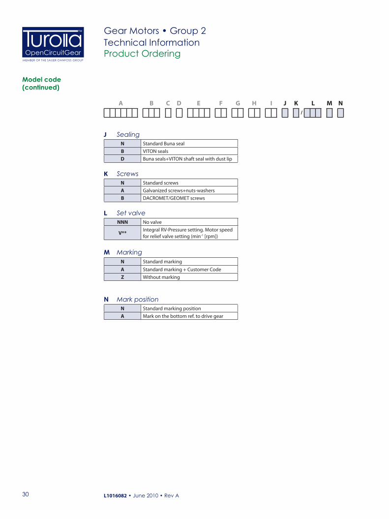
J SealingN Standard Buna sealB VITON sealsD Buna seals+VITON shaft seal with dust lip
K ScrewsN Standard screwsA Galvanized screws+nuts-washersB DACROMET/GEOMET screws
L Set valveNNN No valve
V**Integral RV-Pressure setting. Motor speed for relief valve setting (min-1 [rpm])
M MarkingN Standard marking
A Standard marking + Customer CodeZ Without marking
N Mark positionN Standard marking positionA Mark on the bottom ref. to drive gear
Product Ordering
Model code (continued)
31
OpenCircuitGearMEMBER OF THE SAUER-DANFOSS GROUP
™
L1016082 • June 2010 • Rev A
Gear Motors • Group 2Technical InformationMotor Performance
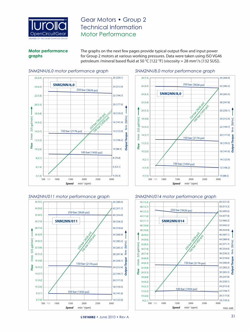
The graphs on the next few pages provide typical output flow and input power for Group 2 motors at various working pressures. Data were taken using ISO VG46 petroleum /mineral based fluid at 50 °C [122 °F] (viscosity = 28 mm2/s [132 SUS]).
Motor performance graphs
SNM2NN/6,0 motor performance graph SNM2NN/8,0 motor performance graph26 [6.9]
24 [6.3]
22 [5.8]
20 [5.3]
18 [4.8]
16 [4.2]
14 [3.7]
12 [3.2]
10 [2.6]
8 [2.1]
6 [1.6]
4 [1.0]
500 700
50 [13.2]
48 [12.7]
46 [12.2]
44 [11.6]
42 [11.1]
40 [10.6]
38 [10.0]
36 [9.5]
34 [9.0]
32 [8.5]
30 [7.9]
28 [7.4]
26 [6.9]
24 [6.3]
22 [5.8]
20 [5.3]
18 [4.8]
16 [4.2]
14 [3.7]
12 [3.2]
10 [2.6]
8 [2.1]
Speed min -1 (r pm)
Flow
l
/min
[U
S g
al/m
in]
2000 2500 1000 1500 3000
SNM2NN/014
100
bar [1
450
psi]
250 bar [3626 psi]
150 bar [2176 psi]
100 bar [1450 psi]
250
bar [3
626
psi]
500 700
36 [9.5]
34 [9.0]
32 [8.5]
30 [7.9]
28 [7.4]
26 [6.9]
24 [6.3]
22 [5.8]
20 [5.3]
18 [4.8]
16 [4.2]
14 [3.7]
12 [3.2]
10 [2.6]
8 [2.1]
6 [1.6]
Speed min -1 (r pm)
Flow
l
/min
[U
S g
al/m
in]
2000 2500 1000 1500 3000
SNM2NN/011
100
bar [1
450
psi]
250 bar [3626 psi]
150 bar [2176 psi]
100 bar [1450 psi]
250
bar [3
626
psi]
500 700
Speed min -1 (r pm)
Flow
l
/min
[U
S g
al/m
in]
2000 2500 1000 1500 3000
28 [7.4]
26 [6.9]
24 [6.3]
22 [5.8]
20 [5.3]
18 [4.8]
16 [4.2]
14 [3.7]
12 [3.2]
10 [2.6]
8 [2.1]
6 [1.6]
4 [1.0]
SNM2NN/6,0250 bar [3626 psi]
100 bar [
1450 psi]
250 bar [
3626 psi]
150 bar [2176 psi]
100 bar [1450 psi]
500 700
Speed min -1 (r pm)
Flow
l
/min
[U
S g
al/m
in]
2000 2500 1000 1500 3000
SNM2NN/8,0
250 bar [3626 psi]
100 bar
[1450 p
si]
250 bar
[3626 p
si]
150 bar [2176 psi]
100 bar [1450 psi]
P005 268E
34 [300.9]
32 [283.2]
30 [265.5]
28 [247.8]
26 [230.1]
24 [212.4]
22 [194.7]
20 [177.0]
18 [159.3]
16 [141.6]
14 [123.9]
12 [106.2]
10 [88.5]
44 [389.4]
42 [371.7]
40 [354.0]
38 [336.3]
36 [318.6]
34 [300.9]
32 [283.2]
30 [265.5]
28 [247.8]
26 [230.1]
24 [212.4]
22 [194.7]
20 [177.0]
18 [159.3]
16 [141.6]
14 [123.9]
60 [531.0]
58 [513.3]
56 [495.6]
54 [477.9]
52 [460.2]
50 [442.5]
48 [424.8]
46 [407.1]
44 [389.4]
42 [371.7]
40 [354.0]
38 [336.3]
36 [318.6]
34 [300.9]
32 [283.2]
30 [265.5]
28 [247.8]
26 [230.1]
24 [212.4]
22 [194.7]
20 [177.0]
18 [159.3]
Ou
tpu
t To
rqu
e N
•m [
lbf•
in]
26 [230.1]
24 [212.4]
22 [194.7]
20 [177.0]
18 [159.3]
16 [141.6]
14 [123.9]
12 [106.2]
10 [88.5]
8 [70.8]
6 [53.1]
4 [35.4]
Ou
tpu
t To
rqu
e N
•m [
lbf•
in]
Ou
tpu
t To
rqu
e N
•m [
lbf•
in]
Ou
tpu
t To
rqu
e N
•m [
lbf•
in]
SNM2NN/011 motor performance graph SNM2NN/014 motor performance graph

32
OpenCircuitGearMEMBER OF THE SAUER-DANFOSS GROUP
™
L1016082 • June 2010 • Rev A
Gear Motors • Group 2Technical InformationMotor Performance
Motor performance graphs (continued)
SNM2NN/017 motor performance graph
P005 269E
85 [22.5]
80 [21.1]
75 [19.8]
70 [18.5]
65 [17.2]
60 [15.9]
55 [14.5]
50 [13.2]
45 [11.9]
40 [10.6]
35 [9.2]
30 [7.9]
25 [6.6]
20 [5.3]
15 [4.0]
10 [2.6]
Speed min -1 (r pm)
Flow
l
/min
[U
S g
al/m
in]
2000 2500 500 0 1000 1500 3000
SNM2NN/025
160 bar [2320 psi]
50 bar [725 psi]
100 bar [1450 psi]
100
bar [
1450
psi]
160
bar [
2320
psi]
85 [22.5]
80 [21.1]
75 [19.8]
70 [18.5]
65 [17.2]
60 [15.9]
55 [14.5]
50 [13.2]
45 [11.9]
40 [10.6]
35 [9.2]
30 [7.9]
25 [6.6]
20 [5.3]
15 [4.0]
10 [2.6]
Speed min -1 (r pm)
Flow
l
/min
[U
S g
al/m
in]
2000 2500 500 0 1000 1500 3000
SNM2NN/022
180 bar [2610 psi]
50 bar [725 psi]
100 bar [1450 psi]
100
bar [1
450
psi]
180
bar [2
610
psi]
60 [15.9]
55 [14.5]
50 [13.2]
45 [11.9]
40 [10.6]
35 [9.2]
30 [7.9]
25 [6.6]
20 [5.3]
15 [4.0]
10 [2.6]
5 [1.3]
Speed min -1 (r pm)
Flow
l
/min
[U
S g
al/m
in]
2000 2500 500 700 1000 1500 3000
SNM2NN/017
100 bar [1450 psi]
250 bar [3626 psi]
100 bar
[1450 p
si]
250 bar
[3626 p
si]
70 [18.5]
65 [17.2]
60 [15.9]
55 [14.5]
50 [13.2]
45 [11.9]
40 [10.6]
35 [9.2]
30 [7.9]
25 [6.6]
20 [5.3]
15 [4.0]
10 [2.6]
5 [1.3]
Speed min -1 (r pm)
Flow
l
/min
[U
S g
al/m
in]
2000 2500 500 0 1000 1500 3000
SNM2NN/019
100 bar [1450 psi]
150 bar [2176 psi]
210 bar [3045 psi]
100
bar [1
450
psi]
210
bar [3
045
psi]
150 bar [2176 psi]
70 [619.6]
65 [575.3]
60 [531.0]
55 [486.8]
50 [442.5]
45 [398.2]
40 [354.0]
35 [309.8]
30 [265.5]
25 [221.3]
20 [177.0]
15 [132.8]
75 [663.8]
70 [619.6]
65 [575.3]
60 [531.0]
55 [486.8]
50 [442.5]
45 [398.2]
40 [354.0]
35 [309.8]
30 [265.5]
25 [221.3]
20 [177.0]
15 [132.8]
10 [88.5]
5 [44.3]
0
70 [619.6]
65 [575.3]
60 [531.0]
55 [486.8]
50 [442.5]
45 [398.2]
40 [354.0]
35 [309.8]
30 [265.5]
25 [221.3]
20 [177.0]
15 [132.8]
10 [88.5]
5 [44.3]
Ou
tpu
t To
rqu
e N
•m [
lbf•
in]
75 [663.8]
70 [619.6]
65 [575.3]
60 [531.0]
55 [486.8]
50 [442.5]
45 [398.2]
40 [354.0]
35 [309.8]
30 [265.5]
25 [221.3]
20 [177.0]
15 [132.8]
10 [88.5]
5 [44.3]
0
Ou
tpu
t To
rqu
e N
•m [
lbf•
in]
Ou
tpu
t To
rqu
e N
•m [
lbf•
in]
Ou
tpu
t To
rqu
e N
•m [
lbf•
in]
SNM2NN/025 motor performance graphSNM2NN/022 motor performance graph
SNM2NN/019 motor performance graph

33
OpenCircuitGearMEMBER OF THE SAUER-DANFOSS GROUP
™
L1016082 • June 2010 • Rev A
Gear Motors • Group 2Technical InformationProduct Options
Flange, shaft and port configurations
Flange, shaft and port configurations for SNM2NN and SNU2NN motorsCode Flange Shaft Port
01BAEuropean 01, 4-boltspilot Ø 36.5 mm [1.44 in]
1:8 taperedEuropean in + pattern
02AAEuropean 02, 4-bolts pilot Ø 80 mm [3.15 in]
1:5 taperedGerman standard in X pattern
04AA/05AA
German PTO 2-boltspilot Ø 50 mm [1.97 in]
1:5 taperedGerman standard in X pattern
01FAEuropean 01, 4-boltspilot Ø 36.5 mm [1.44 in]
Ø 15 mm [0.59 in]parallel
European in + pattern
06GASAE A pilot Ø 82.55 mm [3.25 in]
Ø 15.7 mm [0.625 in]parallel
Threaded SAE O-ring boss port
01DAEuropean 01, 4-boltspilot Ø 36.5 mm [1.44 in]
9-teeth splinedm = 1.60, α = 30o
DIN 5482-B17x14
European in + pattern
02DBEuropean 02, 4-bolts pilot Ø 80 mm [3.15 in]
9-teeth splinedm = 1.60, α = 30o
DIN 5482-B17x14
German standard in X pattern
04DB/05DB
German PTO 2-boltspilot Ø 50 mm [1.97 in]
9-teeth splinedm = 1.60, α = 30o
DIN 5482-B17x14
German standard in X pattern
06SASAE A pilot Ø 82.55 mm [3.25 in]
SAE 9-teeth splined
Threaded SAE O-ring boss port
03CATurolla OCG tang pilot Ø 52 mm [2.066 in]
Turolla OCG standard tang
German standard in X pattern

34
OpenCircuitGearMEMBER OF THE SAUER-DANFOSS GROUP
™
L1016082 • June 2010 • Rev A
Gear Motors • Group 2Technical Information
Turolla OCG offers many types of industry standard mounting flanges. The table below shows order codes for each available mounting flange and its intended use
Flange availability A B C D E F G H I J K L M N
/ /
01 European 25.4 mm [1 in] 4-bolt02 European 30 mm [1.18 in] 4-bolt06 SAE A-A
Product Options
Group 2 motors are available with a variety of splined, parallel, and tapered shaft ends. Not all shaft styles are available with all flange styles.
Valid combinations and nominal torque ratings are shown in the table below. Torque ratings assume no external radial loading. Applied torque must not exceed these limits regardless of pressure parameters stated earlier. Maximum torque ratings are based on shaft torsional fatigue strength.
Shaft availability and nominal torque capability A B C D E F G H I J K L M N
/ /
Shaft options
Shaft Mounting flange code with maximum torque in N•m [lb•in]Code Description 01 02 03 04 05 06 09 0BAA Taper 1:5 – 140 [1239] – 140 [1239] 140 [1239] – – –BA Taper 1:8 150 [1328] – – – – – 150 [1328] 150 [1328]DA DIN spline B17x14 90 [797] – – – – – – –DB DIN spline B17x14 – 130 [1151] – 130 [1151] 130 [1151] – – –SA SAE spline 9T 16/32p – – – – – 75 [646] – –SB SAE spline 11T 16/32p – – – – – 150 [1328] – –FA Parallel 15 mm [0.590 in] 90 [797] – – – – – – –GA Parallel 15.875 mm [0.625 in] – – – – – 80 [708]CA Turolla OCG Tang – – 70 [620] – – – – –
Mounting flanges options
Recommended mating splines for Group 2 splined output shafts should be in accordance with SAE J498 or DIN 5482. Turolla OCG external SAE splines are flat root side fit with circular tooth thickness reduced by 0.127 mm [0.005 in] in respect to class 1 fit. The external DIN splines have an offset increased by 0.1 mm [0.004 in.] These dimensions are modified in order to assure a clearance fit with the mating spline.
Other shaft options may exist. Contact your Sauer- Danfoss representative for availability.
C CautionShaft torque capability may limit allowable pressure. Torque ratings assume no external radial loading. Applied torque must not exceed these limits, regardless of stated pressure parameters. Maximum torque ratings are based on shaft torsional fatigue strength.

35
OpenCircuitGearMEMBER OF THE SAUER-DANFOSS GROUP
™
L1016082 • June 2010 • Rev A
Gear Motors • Group 2Technical Information
Various port configurations are available on Group 2 motors. They include:• European standard flanged ports• German standard flanged ports• Gas threaded ports (BSPP)• O-ring boss (following SAE J1926/1 [ISO 11926-1] UNF threads, standard)
Available port configurations for Inlet (G) and Outlet (H) A B C D E F G H I J K L M N
/ /
PortCode Dimension Description
B5 15 x 35 x M6 Flanged port, 4-threaded holes in X pattern, in the center or off-set of the bodyB6 15 x 40 x M6
B7 20 x 40 x M6BB 27 x 55 x M8C2 12 x 26 x M5 Flanged port, 4-threaded holes in + pattern,
(European standard ports)C3 13.5 x 30 x M6C5 13.5 x 40 x M8C7 20 x 40 x M8C8 23.5 x 40 x M8D4 M16 x 1.5 Threaded metric portD5 M18 x1.5D7 M22 x 1.5D9 M26 x 1.5E3 ⁹⁄₁₆–18UNF Threaded SAE , O-ring boss portE4 ¾–16UNFE5 ⁷⁄₈–14UNFE6 1-1⁄₁₆–12UNE8 1-⁵⁄₁₆–12UNF3 ³⁄₈ GAS Threaded GAS (BSPP) portF4 ½ GASF5 ¾ GASF6 1 GASH5 M18 x 1.5 Threaded metric port ISO6149H7 M22 x 1.5H8 M27 x 2H9 M33 x 2
Port configurations
Product Options
36
OpenCircuitGearMEMBER OF THE SAUER-DANFOSS GROUP
™
L1016082 • June 2010 • Rev A
Gear Motors • Group 2Technical InformationProduct Options
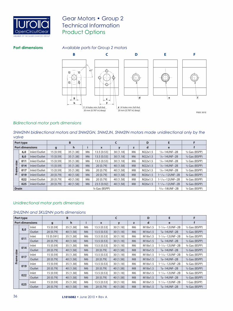
SNM2NN bidirectional motors and SNM2GN, SNM2JN, SNM2IN motors made unidirectional only by the valvePort type B C D E FPort dimensions g h i x y z d e f
Fram
e si
ze
6,0 Inlet/Outlet 15 [0.59] 35 [1.38] M6 13.5 [0.53] 30 [1.18] M6 M22x1.5 7/ 8 –14UNF–2B ½ Gas (BSPP)8,0 Inlet/Outlet 15 [0.59] 35 [1.38] M6 13.5 [0.53] 30 [1.18] M6 M22x1.5 7/ 8 –14UNF–2B ½ Gas (BSPP)011 Inlet/Outlet 15 [0.59] 35 [1.38] M6 13.5 [0.53] 30 [1.18] M6 M22x1.5 7/ 8 –14UNF–2B ½ Gas (BSPP)014 Inlet/Outlet 15 [0.59] 35 [1.38] M6 20 [0.79] 40 [1.58] M8 M22x1.5 7/ 8 –14UNF–2B ½ Gas (BSPP)017 Inlet/Outlet 15 [0.59] 35 [1.38] M6 20 [0.79] 40 [1.58] M8 M22x1.5 7/ 8 –14UNF–2B ½ Gas (BSPP)019 Inlet/Outlet 20 [0.79] 40 [1.58] M6 20 [0.79] 40 [1.58] M8 M26x1.5 1-1/ 16 –12UNF–2B ¾ Gas (BSPP)022 Inlet/Outlet 20 [0.79] 40 [1.58] M6 20 [0.79] 40 [1.58] M8 M26x1.5 1-1/ 16 –12UNF–2B ¾ Gas (BSPP)025 Inlet/Outlet 20 [0.79] 40 [1.58] M6 23.5 [0.92] 40 [1.58] M8 M26x1.5 1-1/ 16 –12UNF–2B ¾ Gas (BSPP)
Drain ¼ Gas (BSPP) 9/ 16 –18UNF–2B ¼ Gas (BSPP)
Unidirectional motor ports dimensions
SNU2NN and SKU2NN ports dimensionsPort type B C D E FPort dimensions g h i x y z d e f
Fram
e si
ze
8,0Inlet 15 [0.59] 35 [1.38] M6 13.5 [0.53] 30 [1.18] M6 M18x1.5 1-1/ 16 –12UNF–2B ½ Gas (BSPP)Outlet 20 [0.79] 40 [1.58] M6 13.5 [0.53] 30 [1.18] M6 M16x1.5 ⁷⁄₈–14UNF–2B ½ Gas (BSPP)
011Inlet 15 [0.591] 35 [1.38] M6 13.5 [0.53] 30 [1.18] M6 M18x1.5 1-1/ 16 –12UNF–2B ¾ Gas (BSPP)Outlet 20 [0.79] 40 [1.58] M6 13.5 [0.53] 30 [1.18] M6 M16x1.5 ⁷⁄₈–14UNF–2B ½ Gas (BSPP)
014Inlet 15 [0.59] 35 [1.38] M6 13.5 [0.53] 30 [1.18] M6 M18x1.5 1-1/ 16 –12UNF–2B ¾ Gas (BSPP)Outlet 20 [0.79] 40 [1.58] M6 20 [0.79] 40 [1.58] M8 M16x1.5 ⁷⁄₈–14UNF–2B ½ Gas (BSPP)
017Inlet 15 [0.59] 35 [1.38] M6 13.5 [0.53] 30 [1.18] M6 M18x1.5 1-1/ 16 –12UNF–2B ¾ Gas (BSPP)Outlet 20 [0.79] 40 [1.58] M6 20 [0.79] 40 [1.58] M8 M18x1.5 ⁷⁄₈–14UNF–2B ½ Gas (BSPP)
019Inlet 15 [0.59] 35 [1.38] M6 13.5 [0.53] 30 [1.18] M6 M18x1.5 1-1/ 16 –12UNF–2B ¾ Gas (BSPP)Outlet 20 [0.79] 40 [1.58] M6 20 [0.79] 40 [1.58] M8 M18x1.5 ⁷⁄₈–14UNF–2B ½ Gas (BSPP)
022Inlet 15 [0.59] 35 [1.38] M6 13.5 [0.53] 30 [1.18] M6 M18x1.5 1-1/ 16 –12UNF–2B ¾ Gas (BSPP)Outlet 20 [0.79] 40 [1.58] M6 20 [0.79] 40 [1.58] M8 M18x1.5 ⁷⁄₈–14UNF–2B ½ Gas (BSPP)
025Inlet 15 [0.59] 35 [1.38] M6 13.5 [0.53] 30 [1.18] M6 M18x1.5 1-1/ 16 –12UNF–2B 1 Gas (BSPP)Outlet 20 [0.79] 40 [1.58] M6 20 [0.79] 40 [1.58] M8 M18x1.5 ⁷⁄₈–14UNF–2B ¾ Gas (BSPP)
Available ports for Group 2 motors
g
CB
h
xy
45o
i (4 holes min. full thd.20 mm [0.787 in] deep)
z (4 holes min. full thd.20 mm [0.787 in] deep)
D FE
d fe
P005 301E
Bidirectional motor ports dimensions
Port dimensions
37
OpenCircuitGearMEMBER OF THE SAUER-DANFOSS GROUP
™
L1016082 • June 2010 • Rev A
Gear Motors • Group 2Technical Information
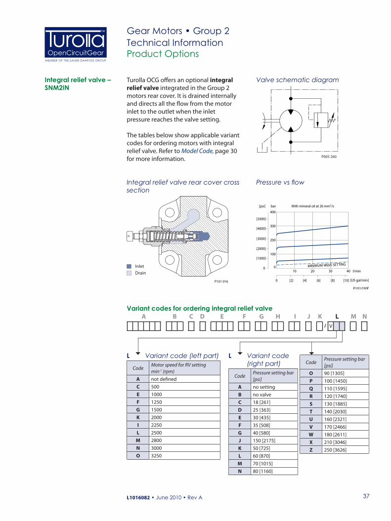
Turolla OCG offers an optional integral relief valve integrated in the Group 2 motors rear cover. It is drained internally and directs all the flow from the motor inlet to the outlet when the inlet pressure reaches the valve setting.
The tables below show applicable variant codes for ordering motors with integral relief valve. Refer to Model Code, page 30 for more information.
Product Options
Integral relief valve – SNM2IN
Inlet
Drain
P101 016
Valve schematic diagram
Integral relief valve rear cover cross section
Pressure vs flow
P005 260
bar
0
[1000]
[2000]
[3000]
[4000]
[5000]
[psi]
l/min
0 [US gal/min]
0
100
200
300
400
With mineral oil at 26 mm2/s
P101 030E
10 3020 40
[10][2] [4] [6] [8]
MINIMUM VALVE SETTING
Variant codes for ordering integral relief valve A B C D E F G H I J K L M N
/ V
L Variant code (left part)
CodeMotor speed for RV setting min-1 (rpm)
A not definedC 500E 1000F 1250G 1500K 2000I 2250L 2500M 2800N 3000O 3250
L Variant code (right part)
CodePressure setting bar [psi]
A no settingB no valveC 18 [261]D 25 [363]E 30 [435]F 35 [508]G 40 [580]J 150 [2175]K 50 [725]L 60 [870]M 70 [1015]N 80 [1160]
CodePressure setting bar [psi]
O 90 [1305]P 100 [1450]Q 110 [1595]R 120 [1740]S 130 [1885]T 140 [2030]U 160 [2321]V 170 [2466]W 180 [2611]X 210 [3046]Z 250 [3626]
38
OpenCircuitGearMEMBER OF THE SAUER-DANFOSS GROUP
™
L1016082 • June 2010 • Rev A
Gear Motors • Group 2Technical InformationProduct Options
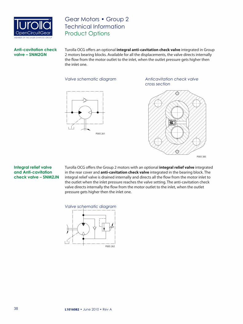
Anti-cavitation check valve – SNM2GN
Turolla OCG offers an optional integral anti-cavitation check valve integrated in Group 2 motors bearing blocks. Available for all the displacements, the valve directs internally the flow from the motor outlet to the inlet, when the outlet pressure gets higher then the inlet one.
Valve schematic diagram
P005 261
Turolla OCG offers the Group 2 motors with an optional integral relief valve integrated in the rear cover and anti-cavitation check valve integrated in the bearing block. The integral relief valve is drained internally and directs all the flow from the motor inlet to the outlet when the inlet pressure reaches the valve setting. The anti-cavitation check valve directs internally the flow from the motor outlet to the inlet, when the outlet pressure gets higher then the inlet one.
Integral relief valve and Anti-cavitation check valve – SNM2JN
Valve schematic diagram
P005 262
P005 385
Anticavitation check valve cross section

39
OpenCircuitGearMEMBER OF THE SAUER-DANFOSS GROUP
™
L1016082 • June 2010 • Rev A
Gear Motors • Group 2Technical InformationProduct Options
An outrigger bearing is available for applications with high radial or thrust loads on the shaft. This option is used primarily for applications with high shaft loads. The design utilizes roller bearings in the front mounting flange. These bearings absorb the radial and thrust loads on the shaft so that the life of the motor is not affected. The use of roller bearings allows life to be described in B10 hours.
Outrigger bearing assembly – SNM2NN
Available configurations A B C D E F G H I J K L M N
/
Flange/Shaft Code* Mounting Flange Shaft9ADB European 4-bolt Taper 1:89FDB German PTO Taper 1:594DB German 4-bolt Taper 1:59HDB SAE A Taper 1:89JDB SAE A Parallel
* Codes represent assembly (complete motor with outrigger bearing).
The table above shows applicable variant codes for ordering motors with outrigger bearing. Refer to Model Code, pages 30 and 31 for more information.

40
OpenCircuitGearMEMBER OF THE SAUER-DANFOSS GROUP
™
L1016082 • June 2010 • Rev A
Gear Motors • Group 2Technical InformationProduct Options
P101 036E
Distance from flange faceto center of radial load
a
0
500
1000
1500
2000
2500
3000
3500
10 20 30 40 50 60
Load
N
Radial Load
Axial Load
0
400
200
800
1200
1600
2000
2400
10 20 30 40 50 60
Load
N
Radial Load
Axial Load
0
400
200
800
1200
1600
2000
2400
10 20 30 40 50 60
Distance a (mm)
Distance a (mm)
Distance a (mm)
Distance a (mm)
Distance a (mm)
Load
N
SNM2NN / 9ADB
Radial Load
Axial Load
0
400
200
800
1200
1600
2000
2400
10 20 30 40 50 60
Load
N
Radial Load
Axial Load
SNM2NN / 9FDB
0
400
200
800
1200
1600
2000
2400
10 20 30 40 50 60
Load
N
Radial Load
Axial Load
SNM2NN / 94DB
SNM2NN / 9JDB
SNM2NN / 9HDB
P005 299E
The graphs below show allowable shaft loads for 1000 hour life at 1500 min-1 (rpm) versus distance from flange face to center of radial load.
Radial load vs distance from flange
Outrigger bearing assembly – SNM2NN(continued)

41
OpenCircuitGearMEMBER OF THE SAUER-DANFOSS GROUP
™
L1016082 • June 2010 • Rev A
Gear Motors • Group 2Technical InformationProduct Options
Outrigger bearing assembly – SNM2NN (continued)
6.5 - 8.5
[0.256 - 0.335]
43
Taper 1:8
] - 0.15 +0.006 - 0.006
+0.15
46.5 [1.831 ] - 0.15 +0.006 - 0.006
+0.15
35
[1.378 ] - 0.15 +0.006 - 0.006
+0.15 43.5
[1.713 ] - 0.15
+0.006 - 0.006
+0.15
20.9
00 -
21.1
25
[0.8
23 -
0.83
2]
4.755
[0.187 ] - 0.030
0 - 0.0012
0
19.05
[0.75 ] - 0.033
- 0.0013
0
3.2
[0.126 ] - 0.025
0 - 0.0010
0
9.5
[0.3
74
] - 0
.35
+0.
006
- 0.0
14
+0.
15
A ±0.50 [0.020]
B ±0.50 [0.020]
C ±0.50 [0.020]
D max
P005 276E
[1.693
0
E max
D max
Taper 1:5
3 [0.118 ]
+0.30-0.109 [0.354 ]
+0.012-0.004
00250.0 -0.025
0-0.001
Dimensions
SNM2NN/.. 9ADB Outrigger bearing 9ADBSNM2NN/.. 03DB
SNM2NN/.. 94DB Outrigger bearing 94DBSNM2NN/.. 03DB
SNM2NN/.. 9JDB Outrigger bearing 9JDBSNM2NN/.. 03DB
mm[in]

42
OpenCircuitGearMEMBER OF THE SAUER-DANFOSS GROUP
™
L1016082 • June 2010 • Rev A
Gear Motors • Group 2Technical Information
DimensionsFrame size 6,0 8,0 011 014 017 019 022 025
Dimension
A45
[1.772]45
[1.772]49
[1.929]52
[2.047]52
[2.047]56
[2.205]59
[2.323]59
[2.323]
B38.6
[1.520]40.6
[1.598]45
[1.772]45
[1.772]45
[1.772]45
[1.772]52.5
[2.067]62
[2.441]
C45
[1.772]47
[1.850]49
[1.929]52
[2.047]54
[2.126]56
[2.205]59
[2.323]61
[2.402]
D93.5
[3.681]97.5
[3.839]101.5
[3.996]107.5
[4.232]111.5
[4.390]115.5
[4.574]121.5
[4.783]125.5
[4.941]
E85
[3.346]89
[3.504]93
[3.661]99
[3.897]103
[4.055]107
[4.212]113
[4.448]117
[4.606]
6 [0.236]
- 0.030 0
4
- 0.0012 0 [0.157 ]
44.22 - 45.88
[1.741 - 1.806]
35
[1.378 ] - 0.05 +0.002 - 0.002
+0.05
34
[1.339 ] - 0.10 +0.004 - 0.004
+0.10
- 0.20 0 8
- 0.0012 0 [0.157 ]
40.48 - 39.32
[1.594 - 1.548]
P005 277E
A ±0.50 [0.020]
B ±0.50 [0.020]
D max
D max
Taper 1:5
Taper 1:8
4 0 -0.030
0 -0.001 [0.158 ]
[0.374 ] 9.5 +0.15 -0.25
+0.006 -0.010
[0.421 ] 10.7 +0.30 -0.10
+0.012 -0.004
Product Options
Outrigger bearing assembly – SNM2NN (continued)
mm[in]
Dimensions (continued)
SNM2NN/.. 9FDB Outrigger bearing 9FDBSNM2NN/.. 03DB
SNM2NN/.. 9HDB Outrigger bearing 9HDBSNM2NN/.. 03DB
Our Products
Aluminum Gear Pumps
Aluminum Gear Motors
Cast Iron Gear Pumps
Cast Iron Gear Motors
Fan Drive Gear Motors Aluminum
Fan Drive Gear Motors Cast Iron
Turolla OpenCircuitGear™ Turolla OCG, with more than 60 years of experience in designing and manufacturing gear pumps, gear motors and fan drive motors of superior quality, is the ideal partner ensuring robustness and reliability to your work functions.
We are fast and responsive - the � rst to specify a customer product, the most experienced in providing technical knowledge and support for fan drive solutions.
We o� er a lean value chain to our partners and customers and the shortest lead time in the market.
Turolla OCG is member of the Sauer-Danfoss Group.
Local address: Turolla OpenCircuitGearVia Villanova 28 40050 Villanova di CastenasoBologna, ItalyPhone: +39 051 6054411Fax: +39 051 6053033
Turolla OpenCircuitGearKukučínova 2148-8401701 Považská Bystrica, SlovakiaPhone: +421 424 301 544Fax: +421 424 301 626
Turolla OpenCircuitGear2800 East 13th StreetAmes, IA 50010 USAPhone: +1 515 239 6000Fax: +1 515 239 6618
OpenCircuitGearMEMBER OF THE SAUER-DANFOSS GROUP
™
www.TurollaOCG.comL1016082 • June 2010 • Rev A