Cyclic Seismic Testing of Composite Concrete-Filled U-Shaped ...

Cyclic Testing of Concrete-Filled Circular Steel Bridge Piershaving Encased Fixed-Based Detail
Julia Marson1 and Michel Bruneau, M.ASCE2
astic testsroposed
efore ateel tubes
Abstract: To investigate their adequacy as energy dissipating elements during earthquakes, this paper reports on cyclic inelexecuted to determine the maximum strength and ductility of four concrete-filled circular steel piers joined to a foundation detail pto develop the full composite strength at the base of these columns. Column diameters considered were 324 and 406 mm, withD/t ratiosranging from 34 to 64. The ductility of all tested columns was found to be good, all columns being able to reach drifts of 7% bsignificant loss in moment capacity occurred as a result of cracks opening on the local buckles, suggesting that concrete-filled scan be effective as bridge piers in seismic regions of North America.
DOI: 10.1061/~ASCE!1084-0702~2004!9:1~14!
CE Database subject headings: Bridge piers; Composite columns; Cyclic tests; Seismic response; Footings; Design criteria.
atiu-
ggkbr
an
a
e
n
-e
il
l
,
far
l-s-
dof
f
.eer
-
d
o
,
unrlr
Introduction
According to the design philosophy prevailing in North Americ~AASHTO 1994; CSA 2000!, bridges are designed to ensure thaduring an earthquake, their superstructure remains elastic whtheir substructure yields and behaves in a ductile manner. Crently in North America, nearly all new highway bridge substructures are constructed of reinforced concrete, even when bridhave a steel superstructure. However, in view of the growinworldwide emphasis on ductile detailing and sound earthquaresistance design, piers made from unstiffened circular steel tufilled with concrete may be an economically viable concept wothy of consideration.
In such a composite pier, among their possible advantages:~1!the steel tube can provide some confinement of the concretepermit development of the full composite capacity of the columwith stable seismic energy dissipation;~2! all the concrete in themember can contribute to strength and ductility of the memberconcrete spalling does not occur;~3! the steel shell can act asformwork for the concrete in a concrete-filled steel column;~4!construction of the bridge may be accelerated if the steel shalone can provide resistance to dead load;~5! the steel compo-nents can be fabricated off site in a controlled environment;~6!the concrete core delays local buckling of the steel tube, aprevents its inward buckling, also enhancing ductility of the composite columns;~7! reinforcing bars are unnecessary in the concrete;~8! there is no need for stain protection on piers when thsuperstructure is of weathering steel~although some protectionmay be necessary at the base depending on the particular deta
1Project Engineer, Harmer Podolak Engineering, 221-39 RobertsRd., Nepean ON, Canada K2H 8R2.
2Director, MCEER, Professor, Dept. of CSEE, Univ. at BuffaloBuffalo, NY 14260. E-mail: [email protected]
Note. Discussion open until June 1, 2004. Separate discussions mbe submitted for individual papers. To extend the closing date by omonth, a written request must be filed with the ASCE Managing EditoThe manuscript for this paper was submitted for review and possibpublication on June 11, 2002; approved on June 24, 2003. This papepart of theJournal of Bridge Engineering, Vol. 9, No. 1, January 1,2004. ©ASCE, ISSN 1084-0702/2004/1-14–23/$18.00.
14 / JOURNAL OF BRIDGE ENGINEERING © ASCE / JANUARY/FEBRUA
ler-
es
ees-
nd,
s
ll
d-
ing
used, it can be accomplished easier there!; and ~9! the final aes-thetics of a concrete-filled steel column are compatible with cur-rent bridge design practice.
The potential economical advantages of concrete-filled steecolumns in tall buildings have long been recognized~Tarics1972!. In North America and Australia, concrete-filled steel col-umns have recently been used in some buildings~e.g., Bauer1988; Webb and Peyton 1990!, and much earlier in nonbuildingapplications, as pylons for hydroelectric lines in Switzerland~Vogeli 1950!, and as piles in many applications. A four levelinterchange was built in Almondsbury, U.K., and supported onconcrete-filled steel piers~Kerensky and Dallard 1968!. This sug-gests that filling a steel tube with concrete can be cost effectiveand~if shown to have good ductile behavior! desirable to providesatisfactory seismic performance.
A literature review revealed that while a significant number ofaxial compression tests have been conducted, there has beenfewer flexural cyclic tests~Marson and Bruneau 2000!. From theresults of seven researchers who have looked at 49 circular coumns subjected to both axial and bending forces, only 12 columnhave been subjected to cyclic loading. Furthermore, in these studies, the largest circular concrete-filled column subjected to cyclicloading had a diameter of 320 mm and most researchers weldethe base of the steel tube to a thick steel plate unrepresentativepossible field conditions.
In the above perspective, this paper reports on cyclic inelastictests executed to determine the maximum strength and ductility ofour concrete-filled circular steel tube columns, of either 324 or407 mm in diameter, and joined to a foundation detail proposed todevelop the full composite capacity at the base of these columnsResults from these experiments were also used to support thdevelopment of design equations presented in a companion pap~Bruneau and Marson 2004!.
Literature Review
While considerable knowledge exists on the behavior of noncyclically loaded composite columns~Viest et al. 1997!, the behaviorof concrete-filled unstiffened steel tubes subjected to repeatecycles of large inelastic deformations is less understood.
n
ste.eis
RY 2004

o
o
m
l
c
t
t
nt
e
tr
r-tehil-c-
y
or-t
-
Boyd et al. ~1995! subjected five circular composite columnspecimens to cyclic inelastic lateral displacements under a cstant axial load. All columns had a diameter,D, of 203.2 mm andthe steel shell thickness,t, was either 1.91 or 2.77 mm~for D/tratios of 106 and 73, respectively!. The footing of the column wasattached to the laboratory strong floor with bolts in order to prvide full base fixity. Although local buckling occurred in all of theshells, all columns exhibited stable behavior and maintained,exceeded, the ACI 318-89 predicted load capacity at a minimudisplacement ductility,m, of 6. The presence of shear studs insome specimens reduced strength degradation at large defortions, thus slightly increasing total energy dissipation.
Other researchers considered high strength concrete. PrionBoehme~1994! tested three specimens with 152 mm outside dameter and 1.65 mm steel shell thickness~for high D/t ratios of92!, and a concrete cylinder strength of 92 MPa. The cyclic tesdemonstrated good ductility and energy dissipation of the mebers. Slight pinching in the hysteretic curves was observed aattributed to the opening and closing of concrete cracks while tsteel tube was yielding and buckling. Fracture of the steel tuoccurred on the tension side at a strain of approximately thrtimes the yield strain. Alfawakiri~1997! tested three hot-formedseamless steel tubes, 3 mm thick and 152 mm in diameter, filwith 72 or 90 MPa high strength concrete. The beam columwere each welded to a thick steel base plate strengthenedmade more rigid by adding two stiffeners to achieve a fixed baconnection. These flexible specimens reached drift in excess7%; testing stopped after the specimens exhibited significant lobuckling, strength degradation, or fracture on a local buckle.
Kitada ~1992! summarized some of the Japanese researchthis topic and showed that the circular cross section is betsuited than the rectangular cross section to sustain, in a ducmanner, numerous cycles of bending, or shear under conscompression.
In the above tests, the lateral force–displacement curve otained under monotonic loading for concrete-filled steel columwas reported to provide an envelope for the behavior expecunder cyclic loading. Stiffness degradation was, typically, observed upon repeated load reversals, but little degradation oftimate strength occurred up to high ductility.
The largest circular concrete-filled column subjected to cyclloading in the above tests had a diameter of 320 mm. Furthmore, most researchers welded the base of the steel tube to a tsteel plate~sometimes with thick base stiffeners! rather than pro-viding a base connection representative of what could be costructed in the field. It also appears that the adequacy of the bobetween the two materials during cyclic testing, and whether tconcrete core becomes triaxially confined by the steel tube,main contentious unresolved issues.
Design of Specimens
Full-Scale Bridges Characteristics and AnalysisTo ensure that the tested specimens had characteristics andmensions representative of real prototypes, full-scale bridges~andtheir piers! were designed according to the Ontario HighwaBridge Design Code~MTO 1991! and the Canadian HighwayBridge Design Code~CSA 2000!. A total of 1296 bridges weredesigned using a suite of different configurations, geometries, aparameters likely to be encountered in highway bridges situain North America. All bridges considered were overpasses caring bidirectional traffic and running perpendicular over a dividehighway. The superstructure of all bridges was designed as a t
JOURNAL
n-
-
orm
ma-
andi-
ts-
ndhebeee
ednsandseofal
onertileant
b-sed-ul-
icr-
hick
n-nd
here-
di-
y
ndedy-dwo
span slab-on-girder bridge. The slab consisted of a 50 mm weaing surface and a 250 mm reinforced concrete deck slab. Concretraffic barriers and sidewalk allowances were designed for botsides of the bridge. The girders were steel I sections readily avaable through Canadian mills and placed at a center-to-center spaing of approximately 2 m. In this parametric design study:• bridges were simply supported or continuous over pier bent;• bridges had 2, 4, or 6 traffic lanes;• individual spans had to accommodate an underpass highwa
of 1, 2, or 3 traffic lanes;• pier heights were 5, 6, or 8 m;• pier bents had 1, 3, or 5 piers;• soil was profile I (S51.0) or profile IV (S52.0) per CSA
2000; and• zonal acceleration ratios,A, were 0.15~Shawinigan, Que.!, 0.2
~Ottawa, Ont.!, 0.3~Vancouver, B.C.!, and 0.4~Victoria, B.C.!.The CAN/CSA-S16.1-M94 standard~CSA 1994! was used for thedesign of the concrete-filled steel pier~due to lack of such provi-sions in the Canadian bridge codes!. Seismic response modifica-tion factors,R, of 3.0 for single column bents and 5.0 for multi-column bents were used.
Fig. 1 summarizes all the resulting full-scale piers that weredesigned. It is observed that many pier sizes could be used fmore than one design. In addition to the criterion of bridge applicability, the following was also considered to select the four tespier specimens.
TheD/t ratio, which relates to the local buckling resistance ofhollow circular flexural members, was retained as a first parameter of significance. According to CAN/CSA.S16.1-M94~CSA1994!, a circular hollow section of yield strength 350 MPa with aD/t ratio less than 37 is a class 1 [email protected]., defined byCSA.S16.1-M94~CSA 1994! as capable of sustained plastic ro-tation after reaching the plastic momentM p], a D/t ratio less than51 is a class 2 section~i.e., defined as able to reachM p but unableto sustain large plastic rotation thereafter!, and aD/t ratio lessthan 67 is a class 3 section~i.e., defined as only able to reach theyield momentM y). Specimens withD/t values near those limitswere desired. For comparison, the AASHTO LRFD bridge designspecifications prescribe a limit of 47 for compact concrete-filledtubes. The AISC LRFD provisions specify a limit of 40 for com-pact hollow tubes, and of 26 in seismic applications.
From the results in Fig. 1, and knowledge from Knowles andPark~1969! that a slenderness ratio,kL/r c less than 35 is requiredto ensure confinement of the concrete fill, the following desired
Fig. 1. Prototype designs~one pier, three piers, and five piers bents!
OF BRIDGE ENGINEERING © ASCE / JANUARY/FEBRUARY 2004 / 15

v
er
e
nd
he
ssss
aa
bar
h
en
eolasn
m-der,
heo
heut
bedto
n
e
1esT
s
,
see-
eg
e
toees
D/t and kL/r c ratio values were deemed desirable for the tesspecimen characteristics:
1. D/t534 andkL/r c530 ~single pier bent! or 60 ~multiplepiers bent!.
2. D/t551 andkL/r c530 ~single pier bent! or 60 ~multiplepiers bent!.
3. D/t551 andkL/r c522 ~single pier bent! or 44 ~multiplepiers bent!.
4. D/t564 andkL/r c522 ~single pier bent! or 44 ~multiplepiers bent!.
@k taken as 1.0 per CAN/CSA S16.1-M94~CSA 1994! sinceP–D analyses were considered in all cases#. As shown in Fig. 1,these four columns fall within the range of possible design revealed by the parametric study for the cases of one, three and fipiers per bent.
Furthermore, to ensure proper consideration of the relativmagnitude of axial forces present in the prototype composite pieduring earthquakes, the ratiosCf /Cr , M f /Mr , Cf /Crc , andCr /Crc were compared for the various possible prototypes to sewhich specimens could be tested to accommodate similar ratioCf andM f are the factored axial load and moment applied to thcolumn, respectively, andCr , Crc , and Mr are the axial resis-tance of the steel tube and composite cross section, and the being resistance of the composite cross section, respectively, asfined in CAN/CSA S16.1-M94~CSA 1994!. Restrictions with thetest setup also impacted selection of the test specimens. Tmaximum axial and horizontal loads that could be applied wer2,000 and 1,000 kN, respectively, and the maximum height of thcolumn was restricted to 2,200 mm.
With this criteria, and using the label CFST]] where CFSTrefers to ‘‘concrete-filled steel tube’’ and the number]] refers tothe D/t ratio of the steel tube, the following four test columnswere chosen:• CFST 51, with a 323.9 mm diameter and a 6.35 mm thicknes• CFST 34, with a 323.9 mm diameter and a 9.53 mm thicknes• CFST 64, with a 406.4 mm diameter and a 6.35 mm thicknes• CFST 42, with a 406.4 mm diameter and a 9.53 mm thicknesNote that it was originally intended to have two columns with thesameD/t ratio of 51. However, the column with aD/t ratio of 51,a kL/r c value of 30, and a 406.4 mm diameter steel tube withsteel thickness of 7.53 mm could not be obtained by the fabrictors, and was substituted by specimen CFST 42.
Design of FoundationA new foundation design concept~for application in actualbridges! was developed to provide full fixity and resist the col-umns’ composite strength. The proposed design consists offoundation in which the full composite flexural strength of thecolumn is resisted by steel components welded to the steel tuand encased inside the concrete foundation. To simplify fabriction and reduce costs, all foundations were designed as if suppoing specimen CFST 42, found to have the largest flexurastrength. The proposed foundation design is shown in Fig. 2.
This system is described per its construction sequence. Tbottom of the steel tube was welded to a 30-mm-thick bottomplate. Two C channels with their flanges pointing away from thtube were placed alongside the steel tube on either side awelded longitudinally to the bottom plate. A 10-mm-thick topplate with a hole cut out for the steel tube was then slipped ovthe column. The two longitudinal ends of the plate were welded tthe top flange of the channels, and the transverse ends of the pthat were in contact with the flanges of the channels were alwelded. The inside of the cut hole was then welded to the colum
16 / JOURNAL OF BRIDGE ENGINEERING © ASCE / JANUARY/FEBRUA
t
-e
s
es.
d-e-
e
e
.
.
.
.
-
a
e-t-l
e
d
r
teo.
The channels and plates were used to transfer the entire coposite moment from the column. The bottom plate was also useto resist the vertical tension and compression that was left in thtube when the load reached the bottom of the column. Howevethe moment was expected to be low on the bottom plate due to tlateral load being transferred into the top plate and channels. Nreinforcing bars were needed in the concrete foundation as tstructural steel members were designed to transfer all forces bsome were added to accommodate the test setup as descrilater. Note that the same design concept could be expandedprovide resistance to the full composite strength of the column itwo orthogonal directions.
MaterialsAverage compressive concrete cylinder strengths~on the day oftesting! of 37, 40, 35, and 35 MPa for CFST 64, CFST 34, CFST42, and CFST 51 were obtained, respectively. The steel for thcolumn was specified Grade C A500~specifiedFy of 350 MPa!,while the plates and channels were specified to be CSA G40.2M-300W steel. The measured yield strengths of the steel tubwere 449, 415, 505, and 405 MPa for CFST 64, CFST 34, CFS42, and CFST 51, respectively~1.16–1.44 times stronger thanordered!. ASTM A500 tube tolerances on steel tube thicknesseare 610%. The measured steel thicknesses for the specimen~asreceived! were 5.5, 7.5, 9.5, and 5.5 mm for CFST 64, CFST 34CFST 42, and CFST 51, respectively, i.e., 15, 27, 0, and 15%smaller than the specified values~ordered!.
Test SetupTests were performed at the University of Ottawa StructureLaboratory. Three independent hydraulic MTS actuators werused for loading each specimen, two for the vertical load and onfor the horizontal load. The foundation was attached to the laboratory strong floor using four high strength bolts~each 64 mm indiameter and 1,800 mm long!. A horizontal loading beam wasused to transfer the vertical axial load from the actuators to thcolumn. Two existing spacers were used to connect the loadinbeam to the column. Fig. 3 illustrates front and side views of thtest assembly.
Due to setup size restrictions, the vertical load actuators hadsit on top of the foundation during testing. Therefore, when thvertical load was applied to axially compress the specimens, thconcrete foundation was subjected to uplifting tension force
Fig. 2. Schematic of foundation connection detail
RY 2004

Fig. 3. Test setup
hthiltce
io
of
wamentsaicdont
veotly
toaag
ldtst
ly
eter-to
–y
sre-tsad
d.en
andethea-ee,
onte
enb-n,
astaleut
%n-
estp
from the actuators. Because the steel tube ran the entire deptthe foundation creating an obstacle to what would have beensimplest path of reinforcement, a reinforcing cage was buaround the column and through the channels to resist the forcaused by the actuators’ upward pull. Concrete was poured up260 mm above the top plate of the embedded steel foundatsystem.
Four bolts running through the swivel head on the bottomeach actuator and through the entire foundation were neededattach the vertical actuators to the foundation.
InstrumentationThirty-six strain gauges were installed on all specimens to alloassessments of the moment in the channels, the shear forcemoment transferred from the steel tube to the top and bottoplates, and flexure and axial forces at various locations in the sttube above and in the foundation. Low voltage displacemetransducers~LVDT ! were used to measure various displacemenof the test setup, column displacement at midheight, and intempts to capture the magnitude of local buckling. A temposondisplacement transducer was used to measure the columnplacement at the horizontal actuator, 2,200 mm above the ccrete foundation. Two other temposonic transducers measuredtip of the column displacement, approximately 1,895 mm abothe concrete foundation, on the north and south side of the cumn, respectively, to monitor whether the column was accidensubjected to torsion during testing.
Experimental Observations
In the following, a positive force or displacement correspondsthe specimen pushed towards the east. A grid was painted on ecolumn for reference during the test to visually facilitate observtion of local buckling. Squares in the grid for columns havindiameters of 406 and 323.9 mm were 50 mm350 mm and 45mm345 mm, respectively.
LoadingIn all tests, the axial load was first applied to the column and heconstant for the duration of the test for each of the experimenCFST 51, CFST 34, CFST 64, and CFST 42 were subjectedaxial loads of 1,600, 1,920, 1,000, and 1,920 kN, respective
JOURNAL O
ofe
ston
to
nd
elt
t-
is--
he
l-
ch-
.o.
The ATC-24 ~ATC 1992! procedure was then followed for alltests. An effective yield displacement was found by observing thforce–displacement curve as the test was progressing, and demining when significant departure from elastic response startedoccur. A visual estimate of the point at which a bilinear forcedisplacement relationship would provide hysteretic energequivalent to the extrapolated experimental one~based on smoothprojection of acquired results! was deemed adequate to define thipoint as the yield displacement. For all tests, significant departufrom the elastic curve occurred at approximately 1% drift. Therefore, the yield deformation was taken as 1% drift and the teswere continued using drift as the prescribed deformation insteof yield displacement.
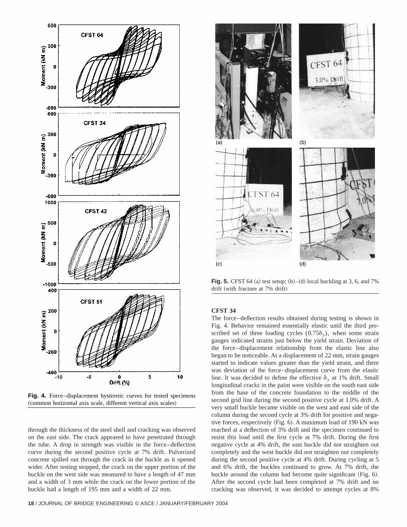
CFST 64Fig. 4 shows the hysteretic force–deflection results recordeDuring testing, no evidence of yielding or damage could be seuntil the third positive cycle at 0.75dy when slight cracking due toseparation on the tension side at the interface of the steel tubeconcrete foundation could be observed. During this cycle, thstrain gauges on the steel tube had not reached yield, andforce–deflection plot still appeared to be a straight line. Deformtion was increased to 22 mm, corresponding to 1% drift, for thnext three cycles. Many of the strain gauges on the steel tubboth in and above the foundation, reached yield in both tensiand compression. The force–deflection curve begun to deviafrom the straight elastic line, and supported by information fromthe strain gauges, it was determined that the yield point had bereached. Slight buckling on the east side of the column was oserved during the second cycle at 2% drift. On reverse excursioslight buckling was also seen on the west side but it was notsignificant as the east side buckle. A maximum applied horizonforce of 164 kN was reached during the cycle at 3% drift. Thbuckle grew on the east side and did not completely straighten oduring the negative cycle at 3% drift~Fig. 5!. Pinching in thehysteretic curve was visible starting at the second cycle of 3drift. From then onward, the buckles on both sides of the columcontinued to grow with the steel remaining ductile in all subsequent cycles~Fig. 5! until the first cycle at 7% drift when a largegap opened between the column and the foundation at the wside. During the negative cycle, necking started to develo
F BRIDGE ENGINEERING © ASCE / JANUARY/FEBRUARY 2004 / 17
ooe
n-
foesrec
e
e-
to
ty
o%
through the thickness of the steel shell and cracking was obseron the east side. The crack appeared to have penetrated thrthe tube. A drop in strength was visible in the force–deflecticurve during the second positive cycle at 7% drift. Pulverizconcrete spilled out through the crack in the buckle as it openwider. After testing stopped, the crack on the upper portion of tbuckle on the west side was measured to have a length of 47and a width of 3 mm while the crack on the lower portion of thbuckle had a length of 195 mm and a width of 22 mm.
Fig. 4. Force–displacement hysteretic curves for tested specim~common horizontal axis scale, different vertical axis scales!
18 / JOURNAL OF BRIDGE ENGINEERING © ASCE / JANUARY/FEBRU
vedughndedhemme
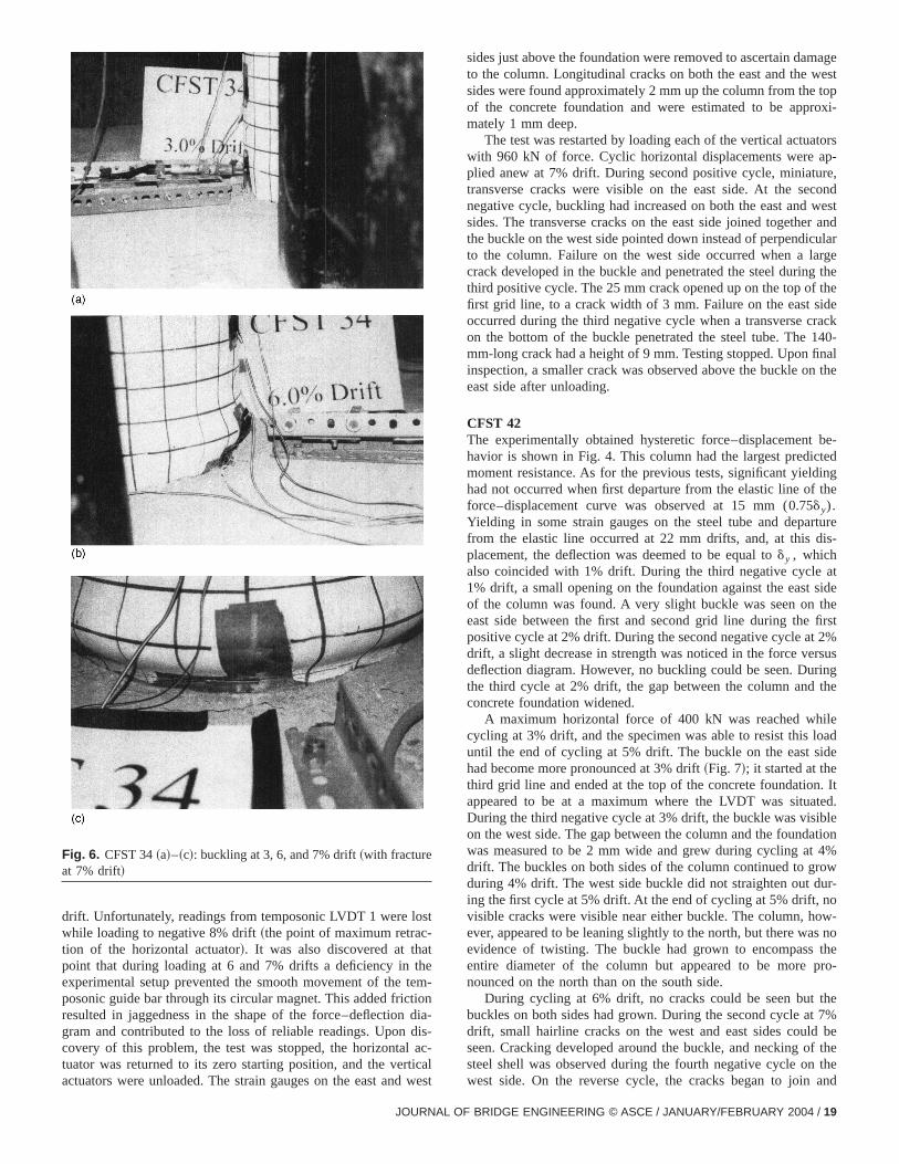
CFST 34The force–deflection results obtained during testing is shown iFig. 4. Behavior remained essentially elastic until the third prescribed set of three loading cycles (0.75dy), when some straingauges indicated strains just below the yield strain. Deviation othe force–displacement relationship from the elastic line alsbegan to be noticeable. At a displacement of 22 mm, strain gaugstarted to indicate values greater than the yield strain, and thewas deviation of the force–displacement curve from the elastiline. It was decided to define the effectivedy at 1% drift. Smalllongitudinal cracks in the paint were visible on the south east sidfrom the base of the concrete foundation to the middle of thesecond grid line during the second positive cycle at 1.0% drift. Avery small buckle became visible on the west and east side of thcolumn during the second cycle at 3% drift for positive and negative forces, respectively~Fig. 6!. A maximum load of 190 kN wasreached at a deflection of 3% drift and the specimen continuedresist this load until the first cycle at 7% drift. During the firstnegative cycle at 4% drift, the east buckle did not straighten oucompletely and the west buckle did not straighten out completelduring the second positive cycle at 4% drift. During cycling at 5and 6% drift, the buckles continued to grow. At 7% drift, thebuckle around the column had become quite significant~Fig. 6!.After the second cycle had been completed at 7% drift and ncracking was observed, it was decided to attempt cycles at 8
ens
Fig. 5. CFST 64~a! test setup;~b!–~d! local buckling at 3, 6, and 7%drift ~with fracture at 7% drift!
ARY 2004
t
e
s
mageest
topoxi-
torsp-re,condwestr andularrge
g thetheiderack140-nal
n the
be-tedingthe
rtureis-
atsidethefirst2%rsusringthe
ileoadide
. Itted.bleation4%
rowur-o
ow-s nothe
pro-
thet 7%
bef thetheand
drift. Unfortunately, readings from temposonic LVDT 1 were loswhile loading to negative 8% drift~the point of maximum retrac-tion of the horizontal actuator!. It was also discovered at thatpoint that during loading at 6 and 7% drifts a deficiency in thexperimental setup prevented the smooth movement of the teposonic guide bar through its circular magnet. This added frictioresulted in jaggedness in the shape of the force–deflection dgram and contributed to the loss of reliable readings. Upon dicovery of this problem, the test was stopped, the horizontal atuator was returned to its zero starting position, and the verticactuators were unloaded. The strain gauges on the east and w
Fig. 6. CFST 34~a!–~c!: buckling at 3, 6, and 7% drift~with fractureat 7% drift!
JOURNAL
m-nia--
c-alest
sides just above the foundation were removed to ascertain dato the column. Longitudinal cracks on both the east and the wsides were found approximately 2 mm up the column from theof the concrete foundation and were estimated to be apprmately 1 mm deep.
The test was restarted by loading each of the vertical actuawith 960 kN of force. Cyclic horizontal displacements were aplied anew at 7% drift. During second positive cycle, miniatutransverse cracks were visible on the east side. At the senegative cycle, buckling had increased on both the east andsides. The transverse cracks on the east side joined togethethe buckle on the west side pointed down instead of perpendicto the column. Failure on the west side occurred when a lacrack developed in the buckle and penetrated the steel durinthird positive cycle. The 25 mm crack opened up on the top offirst grid line, to a crack width of 3 mm. Failure on the east soccurred during the third negative cycle when a transverse con the bottom of the buckle penetrated the steel tube. Themm-long crack had a height of 9 mm. Testing stopped. Upon fiinspection, a smaller crack was observed above the buckle oeast side after unloading.
CFST 42The experimentally obtained hysteretic force–displacementhavior is shown in Fig. 4. This column had the largest predicmoment resistance. As for the previous tests, significant yieldhad not occurred when first departure from the elastic line offorce–displacement curve was observed at 15 mm (0.75dy).Yielding in some strain gauges on the steel tube and depafrom the elastic line occurred at 22 mm drifts, and, at this dplacement, the deflection was deemed to be equal tody , whichalso coincided with 1% drift. During the third negative cycle1% drift, a small opening on the foundation against the eastof the column was found. A very slight buckle was seen oneast side between the first and second grid line during thepositive cycle at 2% drift. During the second negative cycle atdrift, a slight decrease in strength was noticed in the force vedeflection diagram. However, no buckling could be seen. Duthe third cycle at 2% drift, the gap between the column andconcrete foundation widened.
A maximum horizontal force of 400 kN was reached whcycling at 3% drift, and the specimen was able to resist this luntil the end of cycling at 5% drift. The buckle on the east shad become more pronounced at 3% drift~Fig. 7!; it started at thethird grid line and ended at the top of the concrete foundationappeared to be at a maximum where the LVDT was situaDuring the third negative cycle at 3% drift, the buckle was vision the west side. The gap between the column and the foundwas measured to be 2 mm wide and grew during cycling atdrift. The buckles on both sides of the column continued to gduring 4% drift. The west side buckle did not straighten out ding the first cycle at 5% drift. At the end of cycling at 5% drift, nvisible cracks were visible near either buckle. The column, hever, appeared to be leaning slightly to the north, but there waevidence of twisting. The buckle had grown to encompassentire diameter of the column but appeared to be morenounced on the north than on the south side.
During cycling at 6% drift, no cracks could be seen butbuckles on both sides had grown. During the second cycle adrift, small hairline cracks on the west and east sides couldseen. Cracking developed around the buckle, and necking osteel shell was observed during the fourth negative cycle onwest side. On the reverse cycle, the cracks began to join
OF BRIDGE ENGINEERING © ASCE / JANUARY/FEBRUARY 2004 / 19

ktht
n
itohinfecnl
th
--
e
ed
l
een
t
le..
-
necking occurred in the middle of the east side buckle~Fig. 7!. Abang was heard as the crack in the middle of the west bucsuddenly propagated to a length of 260 mm and fractured the sshell. The load dropped to 60 kN at the sixth positive cycle. At tsixth negative cycle, another bang occurred and the crack inmiddle of the east side buckle similarly propagated to a length233 mm and fractured the steel. Testing stopped. Cracks onbottom of the buckle on both the west and east sides hadpenetrated the steel.
CFST 51The experimentally obtained hysteretic force–deflection resuare shown in Fig. 4. Contrary to the previous tests, after the thnegative cycle at 0.75% drift, a very slight buckle was seen onwest side of the column. However, there was still no deviationthe force–displacement curve from the elastic straight line at ttime, and no strain gauges on the steel tube indicated yieldTherefore, the specimen was deemed to still be below the eftive yield displacement. Similar to the previously tested spemens, observed data supported the effective yield displaceme22 mm, corresponding to 1% drift. A small opening was visibon both the east and west sides of the column between the stube and the concrete foundation during the third cycle at 1drift. A slight buckle began to develop on the east side during
Fig. 7. CFST 42~a!–~c!: local buckling at 3, 5, and 7% drift~withfracture at 7% drift!; ~d! specimen after 30 cycles
20 / JOURNAL OF BRIDGE ENGINEERING © ASCE / JANUARY/FEBRU
leeeleheoftheot
ltsrdhefisg.c-i-t ateteel%e
first cycle to 2% drift. Pinching of the force–displacement curveduring the second negative cycle at 2% drift suggested that buckling was occurring somewhere in the steel tube. Upon closer examination the buckle on the west side was visible. Further cyclingat 2% drift produced a larger gap at the steel tube and concretfoundation interface.
A maximum applied horizontal force of 155 kN was reachedduring cycling at 3% drift. The east side buckle became moresignificant by the first cycle to 3% drift and continued to growduring cycling at 3% drift, however, the buckle on the west sidewas smaller in comparison to the buckle on the east side. Thbuckle on the east side completely straightened out upon loareversal until the second negative cycle at 4% drift while thebuckle on the west side fully straightened out upon such reversauntil the first positive cycle to 5% drift. During cycling at 4 and5% drifts, the buckles on both sides grew and the buckle becamvisible around the entire circumference. However, no cracks werseen. The column leaned to the south slightly, and the buckle othe south side was, typically, larger than on the north side.
Vertical cracks became visible on top of the buckle on the wesside during the first negative cycle at 6% drift. After reversing theload, vertical cracks were seen on the northeast side of the buckand the vertical cracks on the west side had completely closed upThe buckle on the southwest side began to droop and point downDuring the first cycle at 7% drift, the buckle on the east side alsobegan to droop and point down instead of developing perpendicular to the column. The negative cycle produced horizontal cracks
Fig. 8. ~a! Steel section after removal from column;~b! column andconcrete after removal of steel section
ARY 2004

Fig. 9. Force–displacement curves with and withoutP–D corrections
thratelslee
7%
desgrd
th
on the bottom and top of the buckle on the east side. Duringnext cycle, the horizontal and vertical cracks began to penetthe thickness of the steel shell. The vertical cracks had compleopened up on the east side during the fourth positive cycle. Aon the east side, a transverse crack was noticed in the middthe buckle, while necking had started on the buckle on the wside. After the next load reversal, the fourth negative cycle of
JOURNAL
etelyo,ofst
drift, a bang was heard and a through thickness fracture occurrein the middle of the buckle on the east side. The length of thcrack was 220 mm and its width was 20 mm. The vertical crackhad penetrated through the thickness of the steel and neckinbecame severe on the west side. Another loud bang was headuring the fifth positive cycle at 7% drift when fracture occurredalong the center of the buckle on the west side. The crack leng
OF BRIDGE ENGINEERING © ASCE / JANUARY/FEBRUARY 2004 / 21

era
k-o
naes
inte
neeasas
e-i,honitt
resf
sxc-
-e
foin
iaol
d.
snh
t
ed
ts
e
he
eds-r-tchrer
ndel
d.he-
.,
2
was 160 mm and the width was 13 mm. On the east side, twovtical cracks had completely penetrated the steel. The test wstopped at this point.
BondTo dispose of the specimens, one cut was made below the bucon the steel tube. The column was then lifted off of the foundation. The concrete at this location was very weak and offered nresistance when the column was removed. Upon closer examition of the foundation, the concrete remaining in the steel tubwas pulverized at the interface but quite cohesive and intact jubelow the foundation. This suggests that only the concrete behthe buckle experienced crushing while the remaining concrecore, above and below the buckle did not crush or fail.
Although not a primary objective in this study, an investigatioof the bond remaining after testing was conducted on specimCFST 51 before it was disposed. A circumferential cut was madapproximately 560 mm above the foundation. The bottom cut wmade above the buckle, approximately 90 mm above the foundtion. A vertical cut was made between these two horizontal lineThe column was then lifted off of the foundation. While stillbeing supported, the column stood vertically on the ground. Thcolumn was tapped twice and the cut section fell off of the concrete core. The steel tube and the remaining column is shownFig. 8. The origin of the crack in the concrete core is not knownhowever, it is suspected that it was caused by the removal of tsteel tube section. There were no signs of concrete cohesionthe steel tube. No concrete residue was left on the steel tube athe concrete core looked smooth. However, there was some whdust on the inside of the steel tube verifying that no significanconcrete shrinkage occurred. The full bond strength was nottained at the end of testing for this column. This investigation wavery limited and only looked at the bond after complete failure oboth the steel and concrete.
Other IssuesAnalysis of test results, using information from the strain gaugepositioned on the steel tube, showed that, in all cases, the mamum moment along the concrete-filled columns generally ocurred below and near the top of the concrete foundation~at most,100 mm into the concrete foundation!. The strain gauge resultsalso indicated that the steel sections used in the foundation~otherthan the tube itself! were subjected to insignificant stresses, suggesting that the concrete foundation likely provided most of thresistance to the composite moment.
Finally, note thatP–D effects on the four tested specimenswere significant, as revealed by the hysteretic curves correctedP–D effects shown in Fig. 9. These effects must be consideredanalysis.
Conclusions
Four concrete-filled steel tubes were subjected to both an axload and a cyclic bending moment. The diameters of these cumns were 324 and 406 mm, with aD/t ratio ranging from 34 to64. All columns were embedded in a special foundation detaileto develop the full plastic moment from the composite columnExperimental work shows that:• The ductility of all tested columns was good, all column
being able to reach drifts of 7% before a significant loss imoment capacity occurred as a result of cracks opening on tlocal buckles.
22 / JOURNAL OF BRIDGE ENGINEERING © ASCE / JANUARY/FEBRUAR
-s
le
-
td
n,
-.
n
ende
-
i-
r
l-
e
• The maximum flexural strength of all columns was reached aapproximately 4% drift.
• Strength deterioration after the maximum strength was reachwas slow until fracture occurred during cycling at 7% drift.
• The favorable hysteretic curves produced from the tesshowed good energy dissipation for all columns.
• The foundation detail worked well, ensuring that full momentresistance capacity of the concrete-filled steel column could bdeveloped during testing~data show that the proposed founda-tion detail could be significantly optimized!.
• No significant bond was seen between the steel tube and tconcrete core after testing had been completed.
These experimentally obtained results suggest that concrete-fillsteel circular tubes could provide an effective mechanism to disipate seismic energy. As such, they could provide a viable altenative for bridge piers in seismic regions of North America, aleast up to the column sizes tested in this study. Future researwill permit us to significantly reduce the foundation sizes, betteunderstand details of the behavior, and investigate whether largcolumns would exhibit the same good behavior.
Acknowledgments
This research program was funded by the Natural Science aEngineering Research Council of Canada and the Structural SteEducation Foundation. This support is sincerely appreciateHowever, the opinions expressed in this paper are those of twriters and do not reflect the views of the aforementioned sponsors.
References
Alfawakiri, F. ~1997!. ‘‘Behavior of high strength concrete-filled circularsteel tube beam columns.’’ MS thesis, Univ. of Ottawa, Ottawa.
American Association of State Highway and Transportation Officials~AASHTO!. ~1994!. ‘‘LRFD bridge design specifications.’’ Washing-ton, D.C.
Applied Technology Council~ATC!. ~1992!. ‘‘Guidelines for cyclic seis-mic testing of components of steel structures.’’Rep. No. ATC-24, Red-wood City, Calif.
Bauer, C. J.~1988!. ‘‘New standards for innovative composite construc-tion.’’ Constr. Specifier,04, 84–89.
Boyd, P., Cofer, W. F., and McLean, D. E.~1995!. ‘‘Seismic performanceof steel-encased concrete columns under flexural loading.’’ACIStruct. J.,92~3!, 355–364.
Bruneau, M., and Marson, J.~2004!. ‘‘Seismic design of concrete-filledcircular steel bridge piers.’’J. Bridge Eng.,9~1!, 24–34.
Canadian Standards Association~CSA!. ~1994!. ‘‘Limit states design ofsteel structures—CAN/CSA-S16.1-94.’’ Rexdale Ont., Canada.
Canadian Standards Association~CSA!. ~2000!. ‘‘Canadian highwaybridge design code—CAN/CSA-S6-00.’’ Rexdale Ont., Canada.
Kerensky, O., and Dallard, N.~1968!. ‘‘The four-level interchange be-tween M4 and M5 motorways at Almodsbury.’’Proc. Inst. Civ. Eng.,Struct. Build.,40, 295–322.
Kitada, T.~1992!. ‘‘Ductility and ultimate strength of concrete-filled steelmembers.’’Stability and ductility of steel structures under cyclic load-ing, U. Fukumoto and G. Lee, eds., CRC Press, Boca Raton, Fla139–148.
Knowles, R. B., and Park, R.~1969!. ‘‘Strength of concrete filled steeltubular columns.’’J. Struct. Div. ASCE,95~12!, 2565–2586.
Marson, J., and Bruneau, M.~2000!. ‘‘Cyclic testing of concrete-filledcircular steel bridge piers having encased fixed-based detail.’’OttawaCarleton Earthquake Eng. Res. Center, Rep. No. OCEERC 00-2,
Y 2004

io,
Univ. of Ottawa, Ottawa.MTO. ~1991!. Ontario highway bridge design code, 3rd Ed., Ministry of
Transportation, Government of Ontario, St. Catherines, OntarCanada.
Prion, H., and Boehme, J.~1994!. ‘‘Beam-column behavior of steel tubesfilled with high strength concrete.’’Can. J. Civ. Eng.,21~2!, 207–218.
Tarics, A. G.~1972!. ‘‘Concrete-filled steel columns for multistory con-struction.’’ Modern Steel Constr., 12, 12–15.
JOURNAL OF
Viest, I. M., Colaco, J. P., Furlong, R. W., Griffis, L. G., Leon, R. T., andWyllie, L. A., Jr. ~1997!. Composite construction design for buildings,American Society of Civil Engineers and McGraw-Hill, New York.
Vogeli, R. ~1950!. ‘‘New transmission lines with concrete filled steel tubetowers.’’ Proc., Int. Conf. Large Electric Systems, 2~223!.
Webb, J., and Peyton, J. M.~1990!. ‘‘Composite concrete-filled steel tubecolumns.’’Proc., 2nd Natl. Structures Conf., The Institution of Engi-neers, Adelaide, Australia, 181–185.
BRIDGE ENGINEERING © ASCE / JANUARY/FEBRUARY 2004 / 23