CUTTHROAT ENERGY Preliminary Design Review
20
CUTTHROAT ENERGY Preliminary Design Review
-
Upload
callum-massey -
Category
Documents
-
view
37 -
download
2
description
CUTTHROAT ENERGY Preliminary Design Review. Sponsored by:. Overview. Electrical Layout. The Problem. Needs. Additional high-speed run 260 rpm ~800V ~1300A 25 sec of additional energy. Deliverables. Documents Problem Description and Requirements Potential Design Solutions - PowerPoint PPT Presentation
Transcript of CUTTHROAT ENERGY Preliminary Design Review
CUTTHROAT ENERGY Preliminary Design Review

Sponsored by:
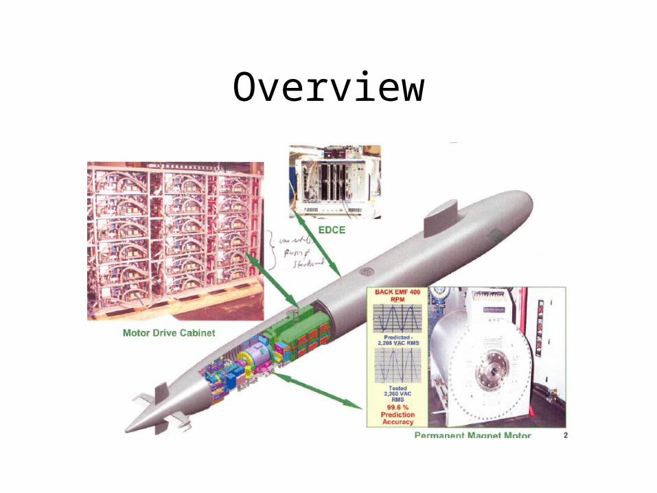
Overview
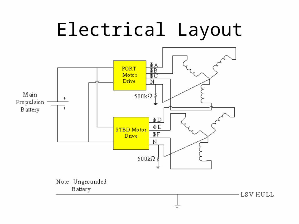
Electrical Layout
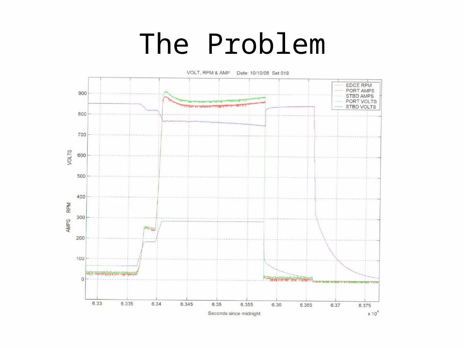
The Problem
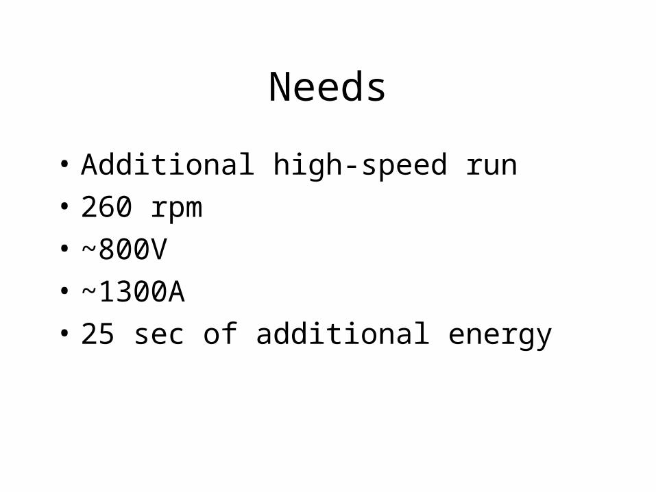
Needs
• Additional high-speed run
• 260 rpm
• ~800V
• ~1300A
• 25 sec of additional energy
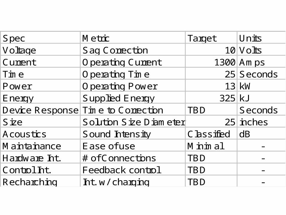
Spec Metric Target UnitsVoltage Sag Correction 10 VoltsCurrent Operating Current 1300 AmpsTime Operating Time 25 SecondsPower Operating Power 13 kWEnergy Supplied Energy 325 kJDevice Response Time to Correction TBD SecondsSize Solution Size Diameter 25 inchesAcoustics Sound Intensity Classified dBMaintainance Ease of use Minimal -Hardware Int. # of Connections TBD -Control Int. Feedback control TBD -Recharching Int. w/ charging TBD -

Deliverables
Documents
• Problem Description and Requirements
• Potential Design Solutions
• Recommended System Selection
• Final Configuration Report
Models
• Laboratory model of scaled system
Project Learning
• PM Motors
• Power Electronics
• Ultracapacitors
• Transient Simulation
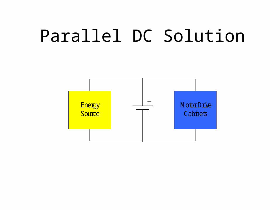
Parallel DC Solution
Energy Source
Motor Drive Cabinets
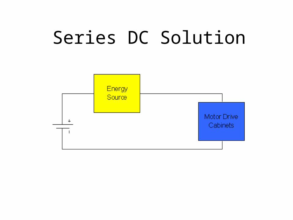
Series DC Solution
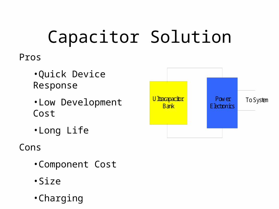
Capacitor Solution
Ultracapacitor Bank
Power Electronics
To System
Pros
•Quick Device Response
•Low Development Cost
•Long Life
Cons
•Component Cost
•Size
•Charging
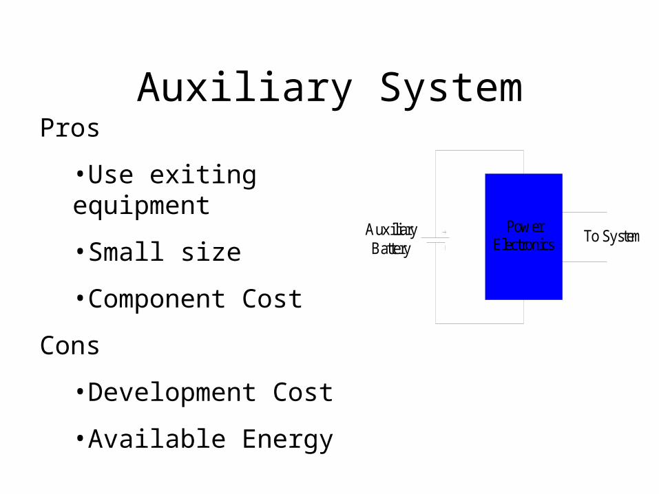
Auxiliary System
Power Electronics
Auxiliary Battery
To System
Pros
•Use exiting equipment
•Small size
•Component Cost
Cons
•Development Cost
•Available Energy
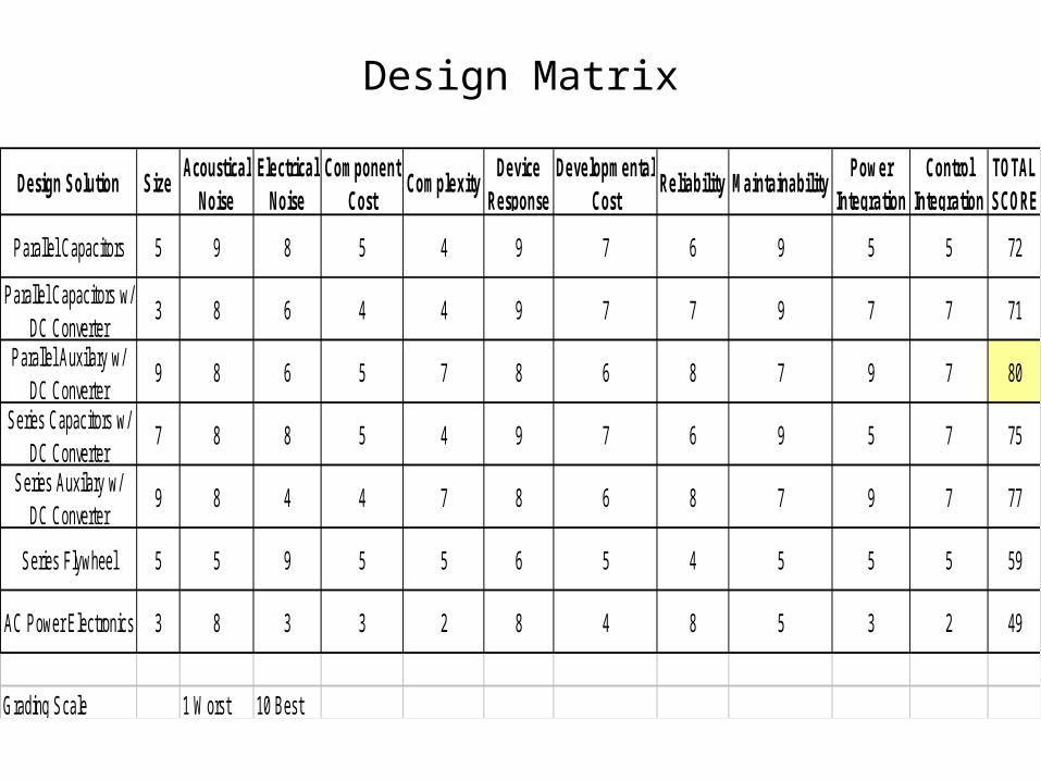
Design Solution SizeAcoustical
NoiseElectrical
NoiseComponent
CostComplexity
Device Response
Developmental Cost
Reliability MaintainabilityPower
IntegrationControl
IntegrationTOTAL SCORE
Parallel Capacitors 5 9 8 5 4 9 7 6 9 5 5 72
Parallel Capacitors w/ DC Converter
3 8 6 4 4 9 7 7 9 7 7 71
Parallel Auxilary w/ DC Converter
9 8 6 5 7 8 6 8 7 9 7 80
Series Capacitors w/ DC Converter
7 8 8 5 4 9 7 6 9 5 7 75
Series Auxilary w/ DC Converter
9 8 4 4 7 8 6 8 7 9 7 77
Series Flywheel 5 5 9 5 5 6 5 4 5 5 5 59
AC Power Electronics 3 8 3 3 2 8 4 8 5 3 2 49
Grading Scale 1 Worst 10 Best
Design Matrix
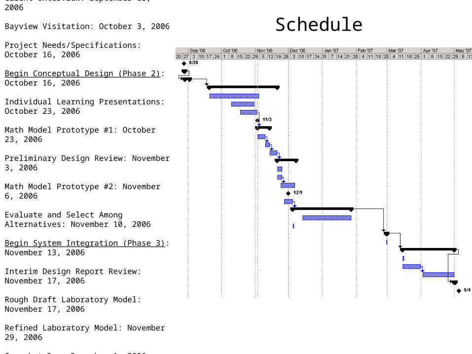
Begin Project Definition (Phase 1): September 8, 2006
Client Interview: September 18, 2006
Bayview Visitation: October 3, 2006
Project Needs/Specifications: October 16, 2006
Begin Conceptual Design (Phase 2): October 16, 2006
Individual Learning Presentations: October 23, 2006
Math Model Prototype #1: October 23, 2006
Preliminary Design Review: November 3, 2006
Math Model Prototype #2: November 6, 2006
Evaluate and Select Among Alternatives: November 10, 2006
Begin System Integration (Phase 3): November 13, 2006
Interim Design Report Review: November 17, 2006
Rough Draft Laboratory Model: November 17, 2006
Refined Laboratory Model: November 29, 2006
Snapshot Day: December 1, 2006
Finalize Proposal/ Project Plan: December 8, 2006
Schedule
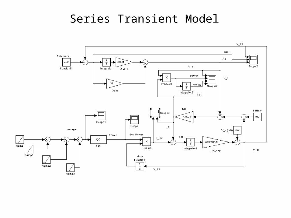
Series Transient Model
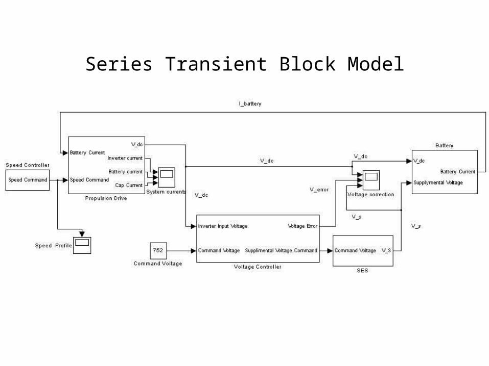
Series Transient Block Model
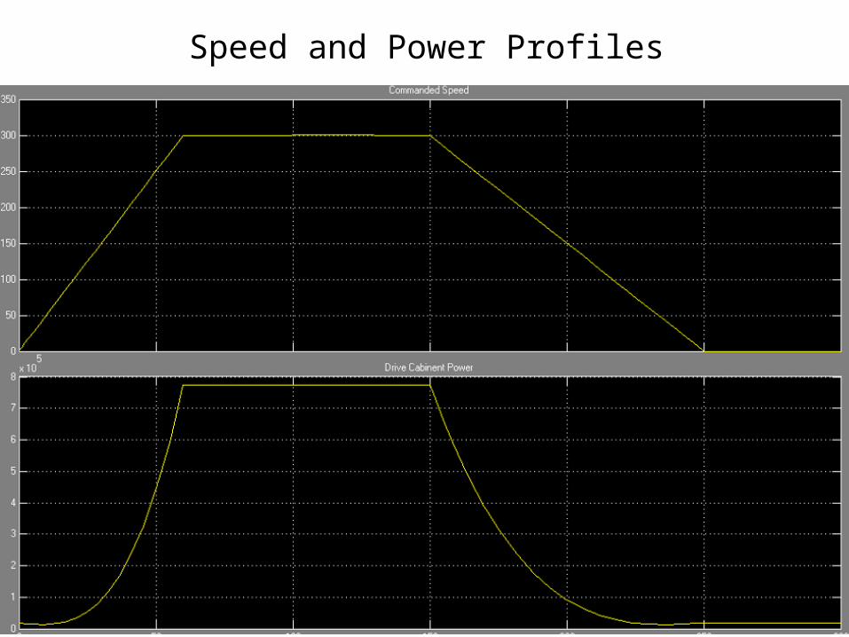
Speed and Power Profiles
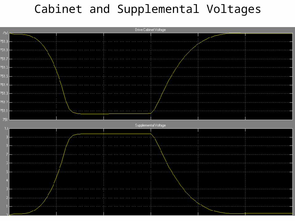
Cabinet and Supplemental Voltages

Questions?