Cutler-Hammer Instructions for Digitrip RMS 510 Trip Unit · Page 2 The Digitrip RMS 510 Trip Unit...
20
lI Cutler-Hammer I.L. 29-8858 Instructions for Digitrip RMS 510 Trip Unit Table of Contents Page 1.0 1.1 1.2 1.3 2.0 3.0 3. 1 3. 2 3. 3 3.4 3.5 3. 6 4. 0 4.1 4.2 4. 3 4.4 4.5 4.6 4.7 4. 8 4.9 5. 0 5. 1 5.2 5. 3 5.4 5.4.1 5.4.2 5.4.3 6. 0 6. 1 6. 2 6.3 7. 0 8. 0 9. 0 9. 1 9. 2 9.3 9.4 General Description .. . .. .. ... . ... . . .. ... 1 Protection . ...... . . . . . . . . .. ............ 1 Information . .... . ... . . .. . . .. . . . . ... . . . . 2 Testing .. .. .. . .. .. .. . . .. . . . . ... .... . . . . 4 UL Listed Devices . . ... .. . .. . . . . .. ... ... . 4 Principle of Operation .. ... . .. .. . . . . . ... .. 4 General .. . . .. ... . . .... . . .... . . . . .. . . .. 4 Trip and Operation Indicators . . . . . . .. .. .. . . 5 Test Provisions . . . .. . . . . . . .. . . . . .. . . ... . 5 DIScriminator (Making Current Release) . ... . 5 OV ERRIDE (Fixed Instantaneous) . .. .... ... 6 Zone Interlocking . . . . . . . . .... . .. .. ..... .. 6 Protection Settings . . . . . . .... ... . . . . .. . . . 6 General . . . . .. . ... . . . . . . . .. .... . .. ... . . 6 Long Delay Current Settings . ... .. .... .... . 7 Long Delay Time Settings . ... . . .. .... .... . 7 Short Delay Current Settings . . . ... ... . .... 8 Short Delay Time Settings . ... .. ..... . . ... 8 Instantaneous Current Settings . . . . . . ... . . . . 8 NO Instantaneous Current Settings . . . .. . . . . 8 Ground Fault Current Settings . .. . .. .... . .. 8 Ground Fault Time Delay Settings . .. . . ... . . 9 Test Procedure . . . . . . . . . . ..... .... .... . 10 General ... . . . .. . .. . . . .. . .. . .... . . . . .. 10 When To Test ... .. .. . . ... .. ... . ... . . .. 11 Test Provision . . . . . . . . . . . . .. . . . . .. . . .. . 11 Conducting Tests. . .. ... .. . ... . . . . ... . . . 11 Control Power . . .. . . . .. . . . ... . .. . ... . . . 11 Not Tripping the Breaker .. . . .. . .... . . . . . . 12 Tripping the Breaker . . . . .. . . . . . . . .. . ... . 12 Battery (Inside the Rating Plug) . . . . . .. ... . 12 General . . . .. . ... .. . . . . . . . . . . . . ... . . .. 12 Battery Check . .. .. . . . .. .. ... . . .. .. . . . . 12 Battery Replacement .. .. . ... . . ... .... . . 12 Auxil iary Power Module... . . . ...... . ... .. 14 Frame Ratings, (where applicable, Sensor Ratings) and Rating Plugs . .. ..... 14 References ... . . . .. . . . . . . ..... .... . .. . 15 Digitrip RMS Trip Assemblies . ... ... .... .. 15 Type OS Low Voltage AC Power Circuit Breakers . .. . . . . . .... . . . . .. . . ... . ... . 15 Type SPB Systems Pow-R Breakers . ... .... 15 Series C1 ® R-Frame Molded Case Circuit Breakers .. . . .. .. .. .. . . .... . . . ... ... 15 Appendix A Zone Interlocking - Example . .... .... . . 15 Effective May 1997, Supersedes I.L . 29·X5A dated September 1994 A WARNING DO NOT ATTEMPT TO INSTALL OR PERFORM MAIN- TENANCE ON EQUIPMENT WHILE IT IS ENERGIZED. DEATH OR SEVERE PERSONAL INJURY CAN RESULT FROM CONTACT WITH ENERGIZED EQUIP- MENT. ALWAYS VERIFY THAT NO VOLTAGE IS PRESENT BEFOR E PROCEEDING WITH THE TASK, AND ALWAYS FOLLOW GENERALLY ACCEPTED SAFETY PROCEDURES. CUTLER-HAMMER IS NOT LIABLE FOR THE MISAPPLICATION OR M ISINSTAL- LATION OF ITS PRODUCTS. It is strongly urged that the user observe all recommen- dations, warnings and cautions relating to the safety of personnel and equipment, as well as general and local health and safety laws, codes, and procedures. The recommendations and information contained herein are based on experience and judgment, but should not be considered to be all-inclusive or covering every appli- cation or circumstance which may arise. If you have any questions or need further information or instructions, please contact your local representative, or the Customer Support Center for the type of circuit breaker you have: Circuit Call Send to B reaker Telephone FAX Type Number Number DS/OSL (412) 937-6029 (412) 937-6396 SPB (412) 937-6029 (412) 937-6396 Series c® R-Frame (412) 937-6490 (412) 937-6010 1.0 GENERAL DESCRIPTION 1.1 Protection The Digitrip RMS 510, illustrated in Fig. 1, is a custom application specific integrated circuit based trip unit suit- able for use in types OS and DSL low voltag, e AC power circuit breakers and type SPB Systems Pow-R circuit breakers and Series c® R-Frame molded case circuit breakers. The Digitrip RMS 510 provides true RMS current sensing for proper correlation with thermal characteristics of con- ductors and equipment. Interchangeable rating plugs are provided to establish the continuous current rating of each circuit breaker. www . ElectricalPartManuals . com
Transcript of Cutler-Hammer Instructions for Digitrip RMS 510 Trip Unit · Page 2 The Digitrip RMS 510 Trip Unit...
l'cGI Cutler-Hammer I .L. 29-8858
Instructions for Digitrip RMS 510 Trip Unit
Table of Contents Page
1. 0 1.1 1.2 1. 3 2.0 3.0 3. 1 3. 2 3. 3 3.4 3.5 3. 6 4. 0 4.1 4.2 4. 3 4.4 4.5 4.6 4.7 4. 8 4.9 5. 0 5. 1 5.2 5. 3 5.4 5.4.1 5.4. 2 5.4.3 6. 0 6. 1 6. 2 6.3 7. 0 8. 0
9. 0 9. 1 9. 2
9.3
9.4
General Description .. . . . . . ... . ... . . . . .. . 1 Protection . ..... . . .. .. . . . . . ... . . . . . . . . . 1 Information . ... . . .. . . . .. . . . . . . . . .. . . .. . 2 Testing . . . . . . . .. . . . . . . . . . . . . .. . .... . . . . 4 UL Listed Devices . . . . . .. . .. . . .. . . .. . .... 4 Principle of Operation .. ... . . . .. . . . . . ... . . 4 General .. . . ... . . . . ... . . . .... . . .. . . .. .. 4 Trip and Operation Indicators . . . . .. .. . . .. . . 5 Test Provisions . . . .. . . . . . . . . . . .. .. . . ... . 5 DIScriminator (Making Current Release) . ... . 5 OV ERRIDE (Fixed Instantaneous) . . . .... ... 6 Zone Interlocking . . . . . . . ... . . . . . .. .... . . . 6 Protection Settings . . . . . . .... ... . .. . .. . . . 6 General . . . .. . ... . . . . . . ... . ... . .. . ... . . 6 Long Delay Current Settings .. . . .. ... . ... . . 7 Long Delay Time Settings . ... .. .. ... . .... . 7 Short Delay Current Settings . . . ... ... . .... 8 Short Delay Time Settings .. . . . . ..... . . ... 8 Instantaneous Current Settings . . . . . . .. . . .. . 8 NO Instantaneous Current Settings . . . .. . . . . 8 Ground Fault Current Settings . . . . . . .. . . . .. 8 Ground Fault Time Delay Settings . .. . . . . . . . 9 Test Procedure . . . . . . .. . . .... . ... . .. . . . 10 General ... . .. .. . . . . . . .. . . . . ... . .. . . .. 10 When To Test ..... .. . . ... . . .... ... . . .. 11 Test Provision . .. . . . . . ... . .. . . . . ... . . . . 11 Conducting Tests . . . . .. . .. . .... . . . ... . . . 11 Control Power . . . . .. . . . . .. .. . . . . . .. . . . . 11 Not Tripping the Breaker . . .. .. . .... . . . . . . 12 Tripping the Breaker . .. . .. . . . . . . . . . . . . . . 12 Battery (Inside the Rating Plug) . . . . . . . .. . . 12 General . . . ... .. . .. . . . . .. . . . . . . ... . . .. 12 Battery Check . . . .. . . . ... . .. . . . . . .. .. .. 12 Battery Replacement .. . . . ... . . .. . .. . . .. 12 Auxiliary Power Module . . . . . . ...... . ... . . 14 Frame Ratings, (where applicable,
Sensor Ratings) and Rating Plugs . . . ... . . 14 References . . . . . . .. . . . . .. .. . . . .. . . . .. . 15 Digitrip RMS Trip Assemblies . .. . .. . .. . . .. 15 Type OS Low Voltage AC Power Circuit
Breakers . ... . . . . ... . . . . . . . . . ... . ... . 15 Type SPB Systems Pow-R Breakers . .. . .... 15
Series C1.4 ® R-Frame Molded Case Circuit Breakers .... .. . . . . .. . . ..... . . . . . ... 15
Appendix A Zone Interlocking - Example . .. . . ... . .. 15
Effective May 1997, Supersedes I.L. 29·885A dated September 1994
A WARNING
DO NOT ATTEMPT TO INSTALL OR PERFORM MAINTENANCE ON EQUIPMENT WHILE IT IS ENERGIZED. DEATH OR SEVERE PERSONAL INJURY CAN RESULT FROM CONTACT WITH ENERGIZED EQUIPMENT. ALWAYS VERIFY THAT NO VOLTAGE IS PRESENT BEFORE PROCEEDING WITH THE TASK, AND ALWAYS FOLLOW GENERALLY ACCEPTED SAFETY PROCEDURES. CUTLER-HAMMER IS NOT LIABLE FOR THE MISAPPLICATION OR MISINSTALLATION OF ITS PRODUCTS.
It is strongly urged that the user observe all recommendations, warnings and cautions relating to the safety of personnel and equipment, as well as general and local health and safety laws, codes, and procedures.
The recommendations and information contained herein are based on experience and judgment, but should not be considered to be all-inclusive or covering every application or circumstance which may arise. If you have any questions or need further information or instructions, please contact your local representative, or the Customer Support Center for the type of circuit breaker you have:
Circuit Call Send to Breaker Telephone FAX Type Number Number
DS/OSL (412) 937-6029 (412) 937-6396
SPB (412) 937-6029 (412) 937-6396
Series c® R-Frame (412) 937-6490 (412) 937-6010
1.0 GENERAL DESCRIPTION
1.1 Protection
The Digitrip RMS 51 0, illustrated in Fig. 1, is a custom application specific integrated circuit based trip unit suitable for use in types OS and DSL low voltag,e AC power circuit breakers and type SPB Systems Pow-R circuit
breakers and Series c® R-Frame molded case circuit breakers.
The Digitrip RMS 510 provides true RMS current sensing for proper correlation with thermal characteristics of conductors and equipment. Interchangeable rating plugs are provided to establish the continuous current rating of each circuit breaker.
www . El
ectric
alPar
tMan
uals
. com
Page 2
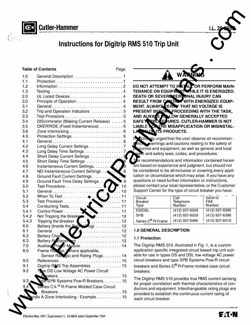
The Digitrip RMS 51 0 Trip Unit is completely self-contained and when the circuit breaker is closed, requires no external control power to operate its protection systems. It operates from current signal levels and control power derived through current sensors integrally mounted in the circuit breaker.
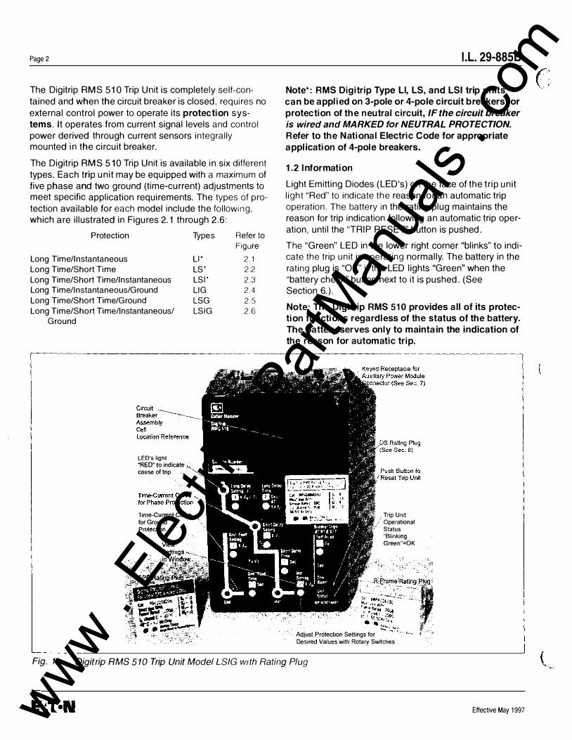
The Digitrip RMS 510 Trip Unit is available in six different types. Each trip unit may be equipped with a maximum of five phase and two ground (time-current) adjustments to meet specific application requirements. The types of protection available for each model include the following, which are illustrated in Figures 2.1 through 2.6:
Protection Types Refer to
Figure
Long Time/Instantaneous Ll* 2.1 Long Time/Short Time LS* 2.2 Long Time/Short Time/Instantaneous LSI* 2.3 Long Time/Instantaneous/Ground LIG 2.4 Long Time/Short Time/Ground LSG 2.5 Long Time/Short Time/Instantaneous/ LSIG 2.6
Ground
I .L. 29-8858
Note*: RMS Digitrip Type Ll, LS, and LSI trip units can be applied on 3-pole or 4-pole circuit breakers for protection of the neutral circuit, IF the circuit breaker is wired and MARKED for NEUTRAL PROTECTION. Refer to the N ational Electric Code for appropriate application of 4-pole breakers.
1.2 Information
Light Emitting Diodes (LED's) on the face of the trip unit light "Red" to indicate the reason for an automatic trip operation. The battery in the rating plug maintains the reason for trip indication following an automatic trip operation, until the "TRIP RESET" button is pushed.
T he "Green" LED in the lower right corner "blinks" to indicate the trip unit is operating normally. The battery in the rating plug is "OK" if the LED lights "Green" when the "battery check" button next to it is pushed. (See Section 6.).
Note: The Digitrip RMS 510 provides all of its protection functions regardless of the status of the battery. The battery serves only to maintain the indication of the reason for automatic trip.
r-------------------·--- - -------------------------------,
Fig. 1
LED's light "'RED" to indicate cause of trip
Tome-Current Curve for Ground Protection
Trip Unit Operational Status "Blinking Green"=OK
Adjust Protection Settings for Desired Values with Rotary Swttches
Digitrip RMS 510 Trip Unit Model LSIG with Rating Plug
Effective May 1997 www . El
ectric
alPar
tMan
uals
. com
I \
I. L. 29-885 8
Fig. 2. 1 Long Time/Instantaneous Protection (LI)
Fig. 2.2 Long Time/Short Time Protection (LS)
Effective May 1997
Fig. 2.3 Long Time/Short Time/Instantaneous
Protection (LSI)
Page 3
Fig. 2.4 Long Time/Instantaneous/Ground Protection
(LIG) www . El
ectric
alPar
tMan
uals
. com
Page 4
�� - - �-- -----�
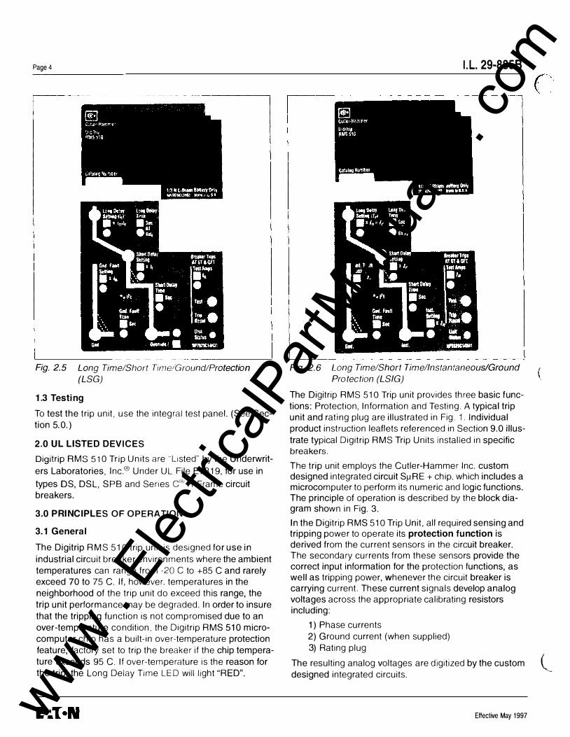
Fig. 2.5 Long Time/Short Time/Ground/Protection (LSG)
1.3 Testing
To test the trip unit, use the integral test panel. (See Section 5.0.)
2.0 UL LISTED DEVICES
Digitrip RMS 510 Trip Units are 'Listed" by the Underwriters Laboratories, Inc.® Under UL File E7819, for use in
types OS, DSL, SPB and Series C") A-Frame circuit breakers.
3.0 PRINCIPLES OF OPERATION
3.1 General
The Digitrip RMS 510 trip unit is designed for use in industrial circuit breaker environments where the ambient temperatures can range from -20 C to +85 C and rarely exceed 70 to 75 C. If, however. temperatures in the neighborhood of the trip unit do exceed this range, the trip unit performance may be degraded. In order to insure that the tripping function is not compromised due to an over-temperature condition. the Digitrip RMS 510 microcomputer chip has a built-in over-temperature protection feature, factory set to trip the breaker if the chip temperature exceeds 95 C. If over-temperature is the reason for the trip, the Long Delay Time LED will light "RED".
I. L. 29-8858
Fig. 2.6 Long Time/Short Time/Instantaneous/Ground Protection (LSIG)
The Digitrip RMS 510 Trip unit provides three basic functions: Protection, Information and Testing. A typical trip unit and rating plug are illustrated in Fig. 1. Individual product instruction leaflets referenced in Section 9.0 illustrate typical Digitrip RMS Trip Units installed in specific breakers.
T he trip unit employs the Cutler-Hammer Inc . custom designed integrated circuit S11RE +chip, which includes a microcomputer to perform its numeric and logic functions. T he principle of operation is described by the block diagram shown in Fig. 3.
In the Digitrip RMS 510 Trip Unit, all required sensing and tripping power to operate its protection function is derived from the current sensors in the circuit breaker. T he secondary currents from these sensors provide the correct input information for the protection functions, as well as tripping power, whenever the circuit breaker is carrying current. These current signals develop analog voltages across the appropriate calibrating resistors including:
1) Phase currents 2) Ground current (when supplied) 3) Rating plug
(
The resulting analog voltages are digitized by the custom ( designed integrated circuits.
·-
Effective May 1997 www . El
ectric
alPar
tMan
uals
. com
( '
I.L. 29-8858 Page 5
,----------- --- ------------------- -------------------1 I I ,-------------------�T Flu;,�:��::2�:�,::,�01;:�T1
']' ']' ']' I �--, ,_-------- -----_______: ?,��'[:',��u•l tl loght�<l RED See Secuon 3 5 ) ) j. ;------_j
I I I --1
LOAD /LOWER 1
ondoc3tesCause Q!TRIPilocared Onf<omP;o,.ell SHSf'Won
l]
Integrated Circuit SJ..LRE+ TM Chip
l"PUillt Op.erat•"9Stat
us :£�H�"rn�!;:��·;tl(,
SeeSect•on32
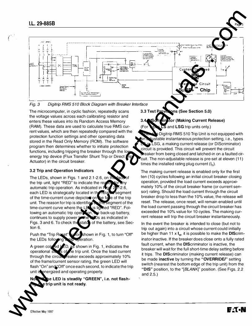
Fig. 3 Digitrip RMS 510 Block Diagram with Breaker In terface
The microcomputer, in cyclic fashion, repeatedly scans the voltage values across each calibrating resistor and enters these values into its Random Access Memory (RAM). These data are used to calculate true RMS current values, which are then repeatedly compared with the protection function settings and other operating data stored in the Read Only Memory (ROM). The software program then determines whether to initiate protection functions, including tripping the breaker through the low energy trip device (Flux Transfer Shunt Trip or Direct Trip Actuator) in the circuit breaker.
3.2 Trip and Operation Indicators
The LEOs, shown in Figs. 1 and 2.1-2. 6, on the face of the trip unit, light "RED" to indicate the reason for any automatic trip operation. As indicated in Figs. 2.1-2. 6, each LED is strategically located in the related segment of the time-current curve depicted on the face of the trip unit. The reason for trip is identified by the segment of the time-current curve where the LED is lighted "RED". Following an automatic trip operation, the back-up battery, continues to supply power to the LEOs as indicated in Figs. 3 and 6. To check the status of the battery, see Section 6.
Push the "Trip Reset" button shown in Fig. 1, to turn "Off' the LEOs following a trip operation.
A green colored LED, as shown in Fig. 1, indicates the operational status of the trip unit. Once the load current through the circuit breaker exceeds approximately 10% of the frame/current sensor rating, the green LED will flash "On" and "Off" once each second, to indicate the trip unit is energized and operating properly.
Note: If the LED is steadily "GREEN", i.e. not flashing, the trip unit is n ot ready.
Effective May 1997
3.3 Test Provisions (See Section 5.0)
3.4 DIScriminator (Making Current Release)
(For Types LS and LSG trip units only.)
When the Digitrip RMS 510 Trip Unit is not equipped with an adjustable instantaneous protection setting, i.e., types LS or LSG, a making current release (or DIScriminator) circuit is provided. This circuit will prevent the circuit breaker from being closed and latched-in on a faulted circuit. The non-adjustable release is pre-set at eleven (11) times the installed rating plug current (In)·
The making current release is enabled only for the first ten ( 1 0) cycles following an initial circuit breaker closing operation, provided the load current exceeds approximately 10% of the circuit breaker frame (or current sensor) rating. Should the load current through the circuit breaker drop to less than the 10% value, the release will reset. The release, once reset, will remain enabled until the load current passing through the circuit breaker has exceeded the 10% value for 10 cycles. The making current release will trip the circuit breaker instantaneously.
In the event the breaker is intended to close (but not to trip out again) into a circuit whose current could initially be higher than 11 x In, it is possible to make the DIScrim
inator inactive. If the breaker does close onto a fully rated fault current, when the DIScriminator is inactive, the breaker will wait for the full short-time delay setting before it trips. The DIScriminator (making current release) can be made inactive by turning the "OVERRIDE/" setting switch (nearest the bottom edge of the trip unit) from the "DIS" position, to the "[BLANK]" position. (See Figs. 2. 2 and 2.5.)
www . El
ectric
alPar
tMan
uals
. com
Page6
Notes:
1 This switch has eight (8) positions, and seven (7) of them show "DIS" in the window, while ONLY ONE position shows "[BLANK]".
2 When the "OVERRIDE/" window shows "[BLANK]", the on ly fast-acting high short-circuit protection available is the OVERRIDE [Fixed Instantaneous]. (See 3.5 below.)
3.5 OVERRIDE (Fixed Instantaneous) (For Types LS And LSG Trip Units Only)
When the Digitrip RMS 5 10 Trip Unit is not equipped with an adjustable instantaneous setting, i .e., types LS or LSG, the Fixed Instantaneous "Override" analog trip circuit is automatically pre-set to a value no greater than the short-time withstand current rating of the circuit breaker in which the trip unit is installed. Since the specific values vary for different circuit breaker types and ratings, refer to t ime-current curves, listed in Section 9, for the values applicable to your breaker. If breaker trips due to high instantaneous current, the "OVERRIDE" LED will light "RED".
3.6 Zone Interlocking
Zone Selective Interlocking (or Zone Interlocking) is available (see Fig. 3) for Digitrip RMS Trip Units having Short Delay and/or Ground Fault protection. Zone Selective Interlocking provides the fastest possible tripping for faults within the breaker's zone of protection, and yet also provides positive coordination among all breakers in the system (mains, ties, feeders and downstream breakers) to limit the outage to the affected part of the system only. When Zone Interlock ing is enabled, a fault within the breaker's zone of protection will cause the RMS DIGITRIP trip unit to:
a) Trip the affected breaker instantaneously, and at the same time
b) Send a signal to upstream RMS DIGITRIP trip units to restrain from tripping immediately. The restraining signal causes the upstream breakers to follow their set coordination times, so that only the minimum service is disrupted, while the fault is cleared in the shortest time possible.
(This signal requires only a single pair of wires from the output terminals of the downstream breaker's trip unit to the input terminals of the upstream breaker's trip unit. For specific instructions see the applicable connection diagrams for your breaker listed in Section 9. 0. )
I.L. 29-8858
Note: If a breaker (M) receives a Zone Interlocking signal from another breaker (F), but the fault current level is less than the trip unit setting for breaker (M), the signal from the other breaker {F) will not cause breaker {M) to trip.
A CAUTION
IF ZONE INTERLOCKING IS NOT TO BE USED (I.E. STANDARD TIME-DELAY COORDINATION ONLY IS INTENDED), THE ZONE INTERLOCKING TERMINALS MUST BE CONNECTED WITH JUMPER WIRES, AS SPECIFIED ON THE CONNECTION DIAGRAMS FOR YOUR BREAKER (SEE SECTION 9.0), SO THE TIMEDELAY SETTINGS WILL PROVIDE THE INTENDED COORDINATION.
For an example of how Zone Selective Interlocking may be used, See Appendix A.
4.0 PROTECTION SETTINGS
4.1 General
Prior to placing circuit breaker in operation, each trip unit protection setting must be set to the values specified by the engineer responsible for the installation. The number of settings that must be made is determined by the protector model supplied as illustrated in Figs. 2.1 through 2.6. Each setting is made with a rotary switch, using a small screwdriver. The selected setting for each adjustment appears in its respective rectangular viewing window as illustrated in Fig. 1.
The installed rating plug establishes the maximum continuous current rating of the circuit breaker (In)· Instanta
neous and ground current settings are defined in multiples of (In).
To illustrate the effect of each protection curve setting, simulated Time-Current curves are pictured on the face of the trip unit. The rotary switch to make each setting is located nearest that portion of the simulated T ime-Current curve it controls. Should an automatic "trip" occur (as a result of the current exceeding the pre-selected value), the LED in the appropriate segment of the simulated T ime-Current curve will light "RED" indicating the reason for "trip".
The available settings, along with the illustrated effect of changing the settings, are given in Figs. 4. 1 through 4.7.
Effective May 1997
(
i
(
www . El
ectric
alPar
tMan
uals
. com
(
I.L. 29-8858
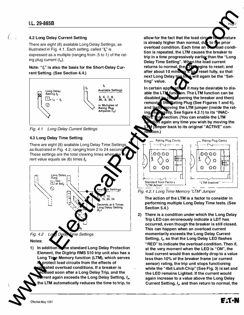
4.2 Long Delay Current Setting
There are eight (8) available Long Delay Settings, as illustrated in Fig. 4.1. Each setting, called "1," is
expressed as a multiple (ranging from .5 to 1) of the rating plug current (In)· Note: "/,''is also the basis for the Short-Delay Cur
rent Setting. (See Section 4.4.)
Lon� Delay Settmg 1,
OJx In � t,
t,
Available Settings
.5, .6, .7, .8, .85, .9, .95, 1 In Multiples of Rating Plug Amperes llnl
Fig. 4. 1 Long Delay Current Settings
4.3 Long Delay Time Setting
There are eight (8) available Long Delay Time Settings, as illustrated in Fig. 4. 2, ranging from 2 to 24 seconds. These settings are the total clearing times when the current value equals six (6) times 1,.
6xt,
Fig. 4.2 Long Delay Time Settings
Notes:
Available Settings
2. 4. 7, 10, 12, 15, 20. 24 Seconds at 6 Times Long Delay Setting (I,)
1) In addition to the standard Long Delay Protection Element, the Digitrip RMS 510 trip unit also has a Long Time Memory function (LTM), which serves to protect load circuits from the effects of repeated overload conditions. If a breaker is reclosed soon after a Long Delay Trip, and the current again exceeds the Long Delay Setting, 1,
the LTM automatical ly reduces the time to trip, to
Effective May 1997
Page 7
allow for the fact that the load circuit temperature is already higher than normal, due to the prior overload condition. Each time an overload condition is repeated, the LTM causes the breaker to trip in a time progressively earlier than the "Long Delay Time Setting". When the load current returns to normal, the LTM begins to reset; and after about 10 minutes it has reset fully, so that next Long Delay trip time will again be the "Setting" value.
In certain applications it may be desirable to disable the LTM function. The LTM function can be disabled by (first opening the breaker and then) removing the Rating Plug (See Figures 1 and 6), and lastly moving the LTM jumper (inside the rating plug cavity, See figure 4.2.1) to its "INACTIVE" connection. (You can enable the LTM function again any time you wish by moving the LTM jumper back to its original "ACTIVE" connection.)
Rating Plug Cavity
-�---
©©
----- ---i,./1--- --- -Standard from Factory "L TM Active" -----'
Rating Plug Cavity
-- �----
"L TM Inactive" ------
Fig. 4.2. 1 Long Time Memory "LTM" Jumper
The action of the LTM is a factor to consider in performing multiple Long Delay Time tests. (See Section 5.4. )
2) There is a condition under which the Long Delay Trip LED can erroneously indicate a LOT has occurred, even though the breaker is still closed. This can happen when an overload current momentarily exceeds the Long Delay Current Setting, 1, so that the Long Delay LED flashes
"RED" to indicate the overload condition . Then if, at the very moment when the LED is "ON", the load current would then suddenly drop to a value less than 10% of the breaker frame (or current sensor) rating, the trip unit stops functioning while the "4bit Latch Chip" (See Fig. 3) is· set and the LED remains Lighted. If the current would again increase to a value above the Long Delay Current Setting, 1, and then return to normal, the
www . El
ectric
alPar
tMan
uals
. com
PageS
LOT wil l reset itself. You can of course, manually clear the LOT (or any other trip indication) at any time, by pushing the "PUSH to RESET" button. (See Figure 1.)
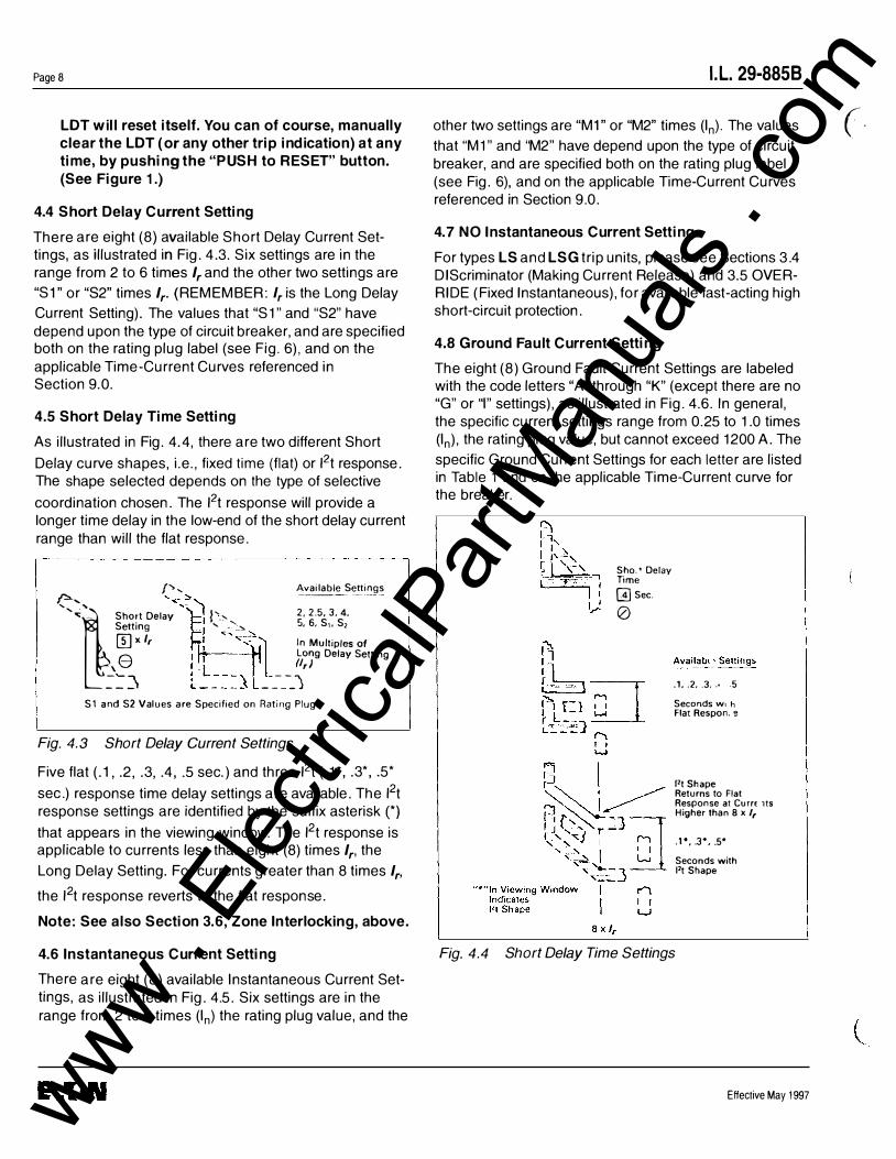
4.4 Short Delay Current Setting
There are eight (8) available Short Delay Current Settings, as illustrated in Fig. 4.3. Six settings are in the range from 2 to 6 times 1, and the other two settings are
"S1" or "S2" times 1,. (REMEMBER: I, is the Long Delay
Current Setting). The values that "S1" and "S2" have depend upon the type of circuit breaker, and are specified both on the rating plug label (see Fig. 6), and on the applicable Time-Current Curves referenced in Section 9.0.
4.5 Short Delay Time Setting
As illustrated in Fig. 4.4, there are two different Short
Delay curve shapes, i.e. , fixed time (flat) or 12t response. The shape selected depends on the type of selective
coordination chosen. The 12t response will provide a longer time delay in the low-end of the short delay current range than will the flat response.
f'>, Available Settings r->-.... '� ---·-- -· ..... ,..,�"'_ Short Delay '� j',, 2, 2.5, 3. 4.
Setting c1 ' .. �'_..,. 5, 6, S,, S,
(5] ' 1, fj: '�-r� '' Mol<'pt" of
e I ; I L Long Delay Setting
�-::� L�-��=� ------�,) S1 and S2 Values are Specified on Rating Plug
Fig. 4.3 Short Delay Current Settings
Five flat (.1, .2, .3, .4 , .5 sec.) and three 12t (.1 *, .3*, .5*
sec.) response time delay settings are available. The 12t response settings are identified by the suffix asterisk (*) that appears in the viewing window. The 12t response is applicable to currents less than eight (8) times 1,, the
Long Delay Setting. For currents greater than 8 times 1,,
the 12t response reverts to the flat response.
Note: See also Section 3.6, Zone Interlocking, above.
4.6 Instantaneous Current Setting
There are eight (8) available Instantaneous Current Settings, as illustrated in Fig. 4.5. Six settings are in the range from 2 to 6 times (In) the rating plug value, and the
I.L. 29-8858
other two settings are "M1" or "M2" times (In)· The values
that "M1" and "M2" have depend upon the type of circuit breaker, and are specified both on the rating plug label (see Fig. 6), and on the applicable Time-Current Curves referenced in Section 9. 0.
4. 7 NO Instantaneous Current Setting
For types LS and LSG trip units, please see Sections 3.4 DIScriminator (Making Current Release) and 3.5 OVERRIDE (Fixed Instantaneous), for available fast-acting high short-circuit protection.
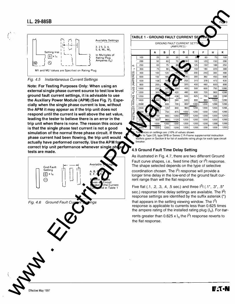
4.8 Ground Fault Current Setting
The eight (8) Ground Fault Current Settings are labeled with the code letters "A" through "K" (except there are no "G" or "I" settings), as illustrated in Fig. 4. 6. In general, the specific current settings range from 0.25 to 1.0 times (In), the rating plug value, but cannot exceed 1200 A. The
specific Ground Current Settings for each letter are listed in Table 1 and on the applicable Time-Current curve for the breaker.
Sho.• Delay Time � Sec. 0
.1 • . 2 .. 3, .• .5 Seconds w1 h Flat Respon. e
Ft Shape Returns to Flat Response at Curre lis Higher than 8 x 1,
. t •, .34 i .5.
Seconds with l>t Shape
Fig. 4.4 Short Delay Time S ettings
Effective May 1997
( .
(
www . El
ectric
alPar
tMan
uals
. com
(
I.L. 29-8858
:""' r-. 1...,..1 Ill I I 1(1 I I I I .......
Setting lnst I L ;-J ITJx In : --\ ® (S) I_---
['" Available Setti ngs ------I I 2. 2.5, 3. 4,
5. 6, M,, M,
,____ In Multiples of Rating Plug Amperes On)
M1 and M2 Values are Specified on Rating Plug
Fig. 4.5 Ins tantaneous Current Settings
Note: For Testing Purposes Only: When using an external single phase current source to test low level ground fault current settings, it is advisable to use the Auxil iary Power Module (APM) (See Fig. 7). Especial ly when the single phase current is low, without the APM it may appear as if the trip unit does not respond until the current is wel l above the set value, leading the tester to bel ieve there is an error in the trip unit when there is none. The reason this occurs is that the single phase test current is not a good simulation of the normal three phase circuit. If three phase current had been flowing, the trip unit would actually have performed correctly. Use the APM for correct trip unit performance whenever single phase tests are made.
[ij Available Settings
Gnd-Fault
� Setting A. 8, C, D, [J xln E. F. H, K
e Specific Values Given on Circuit Breaker Time-Current Curve and in Table 1
Fig. 4.6 Ground Fault Current Settings
Effective May 1997
Page 9
TABL E 1 -GROUND FAULT CURRENT SETIINGS GROUND FAULT CURRENT SETTINGS
(AMPERES) •
A B c D E F H K 100 25 30 35 40 50 60 75 100 200 50 60 70 80 100 120 150 200
§ 250 63 75 88 100 125 150 188 250 c 300 75 90 105 120 150 180 225 300
UJ w 400 100 120 140 160 200 240 300 400 a: w 600 150 180 210 240 300 360 450 600 Q_ 630 158 189 221 252 315 378 473 630 � ::s 800 200 240 280 320 400 480 600 800 (9 1000 250 300 350 ::J 400 500 600 750 1000 _J 1200 300 360 420 480 600 720 900 1200 Q_ (9 1250 312 375 438 500 625 750 936 1200 z � 1600 400 480 560 640 800 960 1200 1200 a: 2000 500 600 700 800 1000 1200 1200 1200 0 2400 600 720 840 960 1200 1200 1200 1200 w _J _J 2500 625 750 875 1000 1200 1200 1200 1200 � 3000/3150 750 900 1050 1200 1200 1200 1200 1200 UJ � 3200 800 960 1120 1200 1200 1200 1200 1200
4000 1000 1200 1200 1200 1200 1200 1200 1200 5000 1200 1200 1200 1200 1200 1200 1200 1200
CD Tolerances on settings are ±1 0% of values shown. •2! Refer to Type DS, type SPB or Series C R-Frame supplemental instruction
leaflets given in Section 9 for list of available rating plugs lor each type circuit breaker.
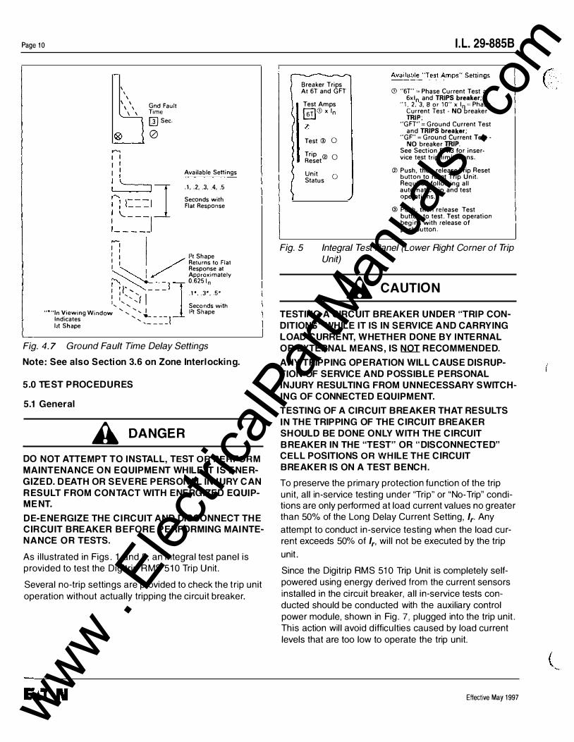
4.9 Ground Fault Time Delay Setting
As illustrated in Fig. 4.7, there are two different Ground
Fault curve shapes, i.e. , fixed time (flat) or 12t response. The shape selected depends on the type of selective
coordination chosen. The 12t response will provide a longer time delay in the low-end of the ground fault current range than will the flat response.
Five flat (.1, .2, .3, .4, .5 sec.) and three 12t (.1*, .3*, .5*
sec.) response time delay settings are available. The 12t response settings are identified by the suffix asterisk (*)
that appears in the setting viewing window. The 12t response is applicable to currents less than 0.625 times the ampere rating of the installed rating plug (In). For cur-
rents greater than 0.625 x In the 12t response reverts to the flat response.
www . El
ectric
alPar
tMan
uals
. com
Page 1 0
\ ' \ \\ Gnd Fault \ \ Time ®'l � Sec.
""' I I I I I I I Available Senings
.1 . . 2 .. 3 . . 4 .. 5 Seconds with Flat Response
,__I I I I 1 l't Shape I 1 / Returns to Flat I Response at � I Approximately
I I ' --- 1 I: ........... .... I .1*,.3*,.5* I ' 'f . .... ' Seconds With
0 � �--1] 0.6251n
"•"In Viewing Window ' , ' .... I Ft Shape Indicates '' .._ - --j l't Shape '----
Fig. 4. 7 Ground Fault Time Delay Settings
Note: See also Section 3.6 on Zone Interlocking.
5.0 TEST PROCEDURES
5.1 General
A DANGER DO NOT ATTEMPT TO INSTALL, TEST OR PERFORM MAINTENANCE O N EQUIPMENT WHILE IT I S ENERGIZED. DEATH OR SEVERE PERSONAL INJURY CAN R ESULT FROM CON TACT WITH ENERGIZED EQUIPMENT.
DE-ENERGIZE THE CIRCUIT AND DISCONNECT THE CIR CUIT BREAKER BEFORE PERFORMING MAINTENANCE O R TESTS.
As illustrated in Figs. 1 and 5, an integral test panel is provided to test the Digitrip RMS 510 Trip Unit.
Several no-trip settings are provided to check the trip unit operation without actually tripping the circuit breaker.
Breaker Trips At 6T and GFT
Test Amps (illCD x 10 l; Test@
0
Trip ® 0 Reset
Unit 0 Status
I.L. 29-8858
<D "6T" =Phase Current Test at 6xln and TRIPS breaker;
"1, 2. 3, 8 or 10" xI =Phase Current Test . NO'breaker TRIP;
"GFT" =Ground Current Test and TRIPS breaker;
"GF" =Ground Current Test -NO breaker TRIP.
See Section 5.4.3 for inservice test trip limitations.
® Push, then release Trip Reset button to reset Trip Unit. Required following all automatic trip and test operations.
@ Push. then release Test button to test. Test operation begins with release of pushbutton.
Fig. 5 Integral Test Panel (Lower Right Corner of Trip Unit)
A CAUTION
TESTING A CIRCUIT BREAKER UNDER "TRIP CONDITIONS" WHILE IT IS IN SERVICE AND CARRYING LOAD CURRENT, WHETHER DONE BY INTERNAL OR EXTERNAL MEANS, IS NOT RECOMMENDED.
ANY TRIPPING OPERATION WILL CAUSE DISRUPTION OF SERVICE AND POSSIBLE PERSONAL INJURY RESULTING FROM UNNECESSARY SWITCHING OF CONNECTED EQUIPMENT.
TESTING OF A CIRCUIT BREAKER THAT RESULTS IN THE TRIPPING OF THE CIRCUIT BREAKER SHOULD BE DONE ONLY WITH THE CIRCUIT BREAKER IN THE "TEST" OR "DISCONNECTED" CELL POSITIONS OR WHILE THE CIRCUIT BREAKER IS ON A TEST BENCH.
To preserve the primary protection function of the trip unit, all in-service testing under "Trip" or "No-Trip" conditions are only performed at load current values no greater than 50% of the Long Delay Current Setting, 1,. Any
attempt to conduct in-service testing when the load current exceeds 50% of 1,, will not be executed by the trip
unit.
Since the Digitrip RMS 510 Trip Unit is completely selfpowered using energy derived from the current sensors installed in the circuit breaker, all in-service tests conducted should be conducted with the auxiliary control power module, shown in Fig. 7, plugged into the trip unit. This action will avoid difficulties caused by load current levels that are too low to operate the trip unit.
Effective May 1997
C . . '
www . El
ectric
alPar
tMan
uals
. com
r •
l·,
I.L. 29-8858
5.2 When To Test
Tests can be conducted with the breaker in the "connected" cell position while carrying load current. However, as stated in the caution note in Section 5.1, good practice will limit circuit breaker in-service "trip tests", where required, to maintenance periods during times of minimum load conditions. Testing, prior to start-up can best be accomplished with the breaker out of its cell or in the ''Test", "Disconnected" or "Withdrawn" (or Removed) cell positions.
Note: Since time-current settings are based on desired system coordination and protection schemes, the protection settings selected and preset in accordance with Section 4.0 above should not be altered during or as a part of any routine test sequence.
5.3 Test Provision
As indicated in Fig. 5, six different "Test Amps" settings (1, 2, 3, 6T, 8 and 1 OX In) are available for testing the
phase elements of the trip unit, and two (GF, GFT) are provided for testing the ground elements.
A CAUTION
A SETTING OF EITHER 6T OR GFT WILL TRIP THE CIRCUIT BREAKER. (SEE SECTION 5.4.3 BELOW.)
For any combination of the phase protection settings, an appropriate "No Trip" condition can be set to test the long time, short time and instantaneous trip settings without tripping the circuit breaker.
In the "GF" test position, the level of test current based on In, is adequate to demonstrate the operating condition of
the trip unit without tripping the circuit breaker. This is a functional check only, not a calibration.
5.4 Conducting Tests
1) Before starting any test sequence, check the Unit Status (Green LEO) in the lower right corner of the trip unit (See Figs. 1 and 5) to be sure it is blinking on and off about once each second, which indi
cates that the trip unit is functioning normally In the event the Unit Status LED is not blinking, install an Auxiliary Power Module (APM) (See Fig. 7}, or if you have one already, check to see that it is connected correctly.
2} If the circuit breaker is carrying current, check
for the following conditions:
Effective May 1997
3)
Page 1 1
a) the current is not less than 1 0% of the breaker frame (or current sensor) rating; be sure the "GREEN" Unit Status LED (in the lower right corner of the trip unit (See Figs. 1 and 5) is blinking on and off (indicating that there is enough current flowing to provide the power necessary to operate the trip unit). In the event the Unit Status LED is either lighted "GREEN" or "OFF" continuously, there is NOT enough current flowing to power the trip unit; and an APM (See Fig. 7) should be installed before proceeding with the test.
and b) the current is not more than 50% of the Long Delay Current Setting (/,); because the trip unit will not execute your test instructions when it senses that the current through the breaker exceeds the 50% level.
When performing tests on the Long Delay element, be aware that in addition to the standard protection element, the Digitrip RMS 510 Trip Unit also has a Long Time Memory function (LTM), which serves to protect load circuits from the effects of repeated overload conditions. (See NOTE 1 under Section 4.3 Long Delay Time Setting.) The action of the LTM will have the same effect of advancing the Long Delay Trip Time if multiple Long Delay Time tests are performed repeatedly - as one might do in making single phase tests on each pole of a breaker in succession, for example. If you have sufficient experience in performing tests with this kind of accelerated trip timing, you may be comfortable with the results of tests performed in quick succession. However, if there is any question, you may simply wait about ten (10) minutes after a Long Delay Trip for the LTM to reset, before you check the next pole.
5.4.1 Control Power
For testing the trip unit, an optional Auxiliary Power Module (Cat. No. P RTAAPM) as shown in Fig. 7 is recommended. T his Auxiliary Power Module, which operates from a separate 120 Vac supply, may be used when a drawout circuit breaker is in any of its four cell positions, i.e. , "Connected", "Test", "Disconnected" and "Withdrawn" (or "Removed.")
Note: For Testing Purposes Only: When using an · external single phase current source to test low level
ground fault current settings, it is advisable to use the Auxiliary Power Module (APM) (See Fig. 7). Especially when the single phase current is low, without
www . El
ectric
alPar
tMan
uals
. com
Page 12
the APM it may appear as if the trip unit does not respond until the current is well-above the set value, leading the tester to believe there is an error in the trip unit when there is none. The reason this occurs is that the single phase test current is not a good simulation of the normal three phase circuit. If three phase current had been flowing, the trip unit would actually have performed correctly. Use the APM for correct trip unit performance whenever single phase tests are made .
Plug in the Auxiliary Power Module (Cat. No. PRTAAPM) to insure control power is available for testing. When the APM is properly connected the "GREEN" Unit Status LED will blink on and off about once per second.
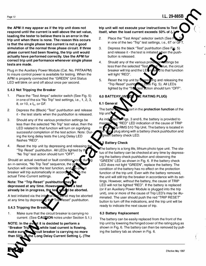
5.4.2 Not Tripping the Breaker
1. Place the "Test Amps" selector switch (See Fig. 5) in one of the six "No Trip" test settings, i.e. , 1, 2, 3, 8, or 10, x In, or GF.
2. Depress the (Black) "Test" pushbutton and release it - the test starts when the pushbutton is released.
3. Should any of the various protection settings be less than the selected "No Trip" test value, then the LED related to that function will turn on signifying successful completion of the test action. Note: During the long delay tests the Long Delay LED flashes "RED".
4. Reset the trip unit by depressing and releasing the 'Trip Reset" pushbutton. All LEOs lighted by the "No Trip" test action should turn "OFF".
Should an actual overload or fault condition occur during an in-service, "No Trip Test" sequence, the protection function will override the test function, and the circuit breaker will trip automatically in accordance with the actual T ime-Current settings.
Note: The "Trip Reset" pushbutton may be depressed at any time. However, should a test already be in progress, the test would be aborted.
A test initiated via the integral test panel may be aborted at any time by depressing the "Trip Reset" pushbutton.
5.4.3 Tripping the Breaker
1. Make sure that the circuit breaker is carrying no current. (See CAUTION notes under Section 5.1.)
NOTE: In the event it is decided to perform a "Breaker Trip Test" while load current is flowing, make sure the circuit breaker is carrying no more than 50% of the Long Delay Current Setting lr (The
I.L. 29-8858
trip unit will not execute your instructions to Test itself, when the load current exceeds 50% of lr) 2. Place the "Test Amps" selector switch (See Fig. 5)
in one of the two "Trip" test settings, i.e. , 6T or GFT.
3. Depress the black "Test" pushbutton (See Fig. 5) and release it - the test is initiated when the pushbutton is released.
4. Should any of the various protection settings be less than the selected 'Test Amps" value, the circuit breaker will trip and the LED related to that function will light "RED".
5. Reset the trip unit by depressing and releasing the 'Trip Reset" pushbutton (See Fig. 5). All LEOs lighted by the 'Trip" test action should turn "OFF".
6.0 BATTERY (INSIDE THE RATING PLUG)
6.1 General
The battery has no part in the protection function of the trip unit.
As indicated in Figs. 3 and 6, the battery is provided to maintain the "RED" LED indication of the cause of T RIP in the Digitrip RMS 510 Trip Unit. The battery is located in the rating plug along with a battery check pushbutton and a green battery check LED.
6.2 Battery Check
T he battery is a long life, lithium photo type unit. The status of the battery can be checked at any time by depressing the battery check pushbutton and observing the "GR EEN" LED as shown in Fig. 6. If the battery check LED does not light "GREEN", replace the battery. The condition of the battery has no effect on the protection function of the trip unit. Even with the battery removed, the unit will still trip the breaker in accordance with its settings. However, without the battery, the cause of T RIP LED will not be lighted "RED". If the battery is replaced (or if an Auxiliary Power Module is plugged into the trip unit), one or more of the cause of Trip LED's may be illuminated. The user should push the red "TRIP RESET" button to turn off the indications, and the trip unit will be ready to indicate the next cause of trip.
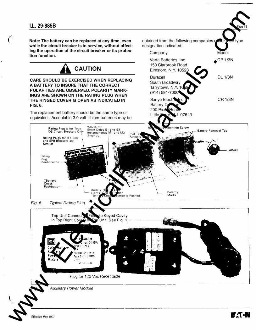
6.3 Battery Replacement
T he battery can be easily replaced from the front of the trip unit by lowering the hinged cover of the rating plug as shown in Fig. 6. The battery can then be removed by pulling the battery tab as shown in Fig. 6.
Effective May 1997
( \
' ,,
www . El
ectric
alPar
tMan
uals
. com
( I.L. 29-8858
Note: The battery can be replaced at any time, even while the circuit breaker is in service, without affecting the operation of the circuit breaker or its protection function.
A CAUTION
CARE SHOULD BE EXERCISED WHEN REPLACING A BATTERY TO INSURE THAT THE CORRECT POLARITIES ARE OBSERVED. POLARITY MARKINGS ARE SHOWN ON THE RATING PLUG WHEN THE HINGED COVER IS OPEN AS INDI CATED IN FIG. 6.
The replacement battery should be the same type or equivalent. Acceptable 3.0 volt lithium batteries may be
Rating Plug 1s for Type OS Circuit Breakers Only I
Rating Plugs for R-Fr arne· and SPB Breakers are Similar
Rat1ng Plug Identification
Fig. 6
"Battery Check" Pushbutton ---...1
Typical Rating Plug
Values for Sho<t Delay S 1 and S2 Instantaneous M1 and M2 Set11llQS
Battery "OK" if LED lights "GREEN" when "Battery Check" Button is Pushed
Page 13
obtained from the following companies under their type designation indicated:
Company Model
Varta Batteries, Inc. 150 Clarbrook Road Elmsford, N.Y. 10523
Duracell South Broadway Tarrytown, N.Y. 10591 (914) 591-7000
Sanyo Electric Inc. Battery Division 200 Riser Road Little Ferry, N.J. 07643
Rating Plug Retention Screw
I
Polarity Marks
CR 1/3N
DL 1/3N
CR 1/3N
Battery Removal Tab
-.-.� .. ,
---------------------------'
,------------------------------------------------------,
Fig. 7
Trip Unit Connector (Fits into Keyed Cavity in Top Right Corner of Tnp Unit See Fig. 1) ------
3?'1(( ,t•,.t �Ot U4t :,., ! 'lt �t Trte t �,.,. � RMS
--------------�---�------------------' Auxiliary Power Module
Effective May 1997 www . El
ectric
alPar
tMan
uals
. com
Page 14
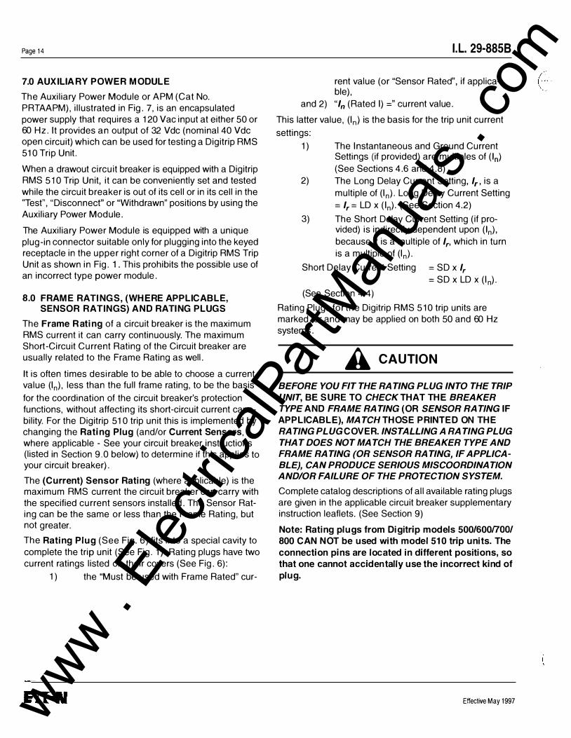
7.0 AUXILIA R Y POWER MODULE
The Auxiliary Power Module or APM (Cat No. PRTAAPM), illustrated in Fig. 7, is an encapsulated power supply that requires a 120 Vac input at either 5 0 or 60 Hz. It provides an output of 32 Vdc (nominal 4 0 Vdc open circuit) which can be used for testing a Digitrip RMS 51 0 Trip Unit.
When a drawout circuit breaker is equipped with a Digitrip RMS 510 Trip Unit, it can be conveniently set and tested while the circuit breaker is out of its cell or in its cell in the ''Test", "Disconnect" or "Withdrawn" positions by using the Auxiliary Power Module.
The Auxiliary Power Module is equipped with a unique plug-in connector suitable only for plugging into the keyed receptacle in the upper right corner of a Digitrip RMS Trip Unit as shown in Fig. 1. This prohibits the possible use of an incorrect type power module.
8.0 FRAME RATINGS, (WHERE APPLICABLE, SENSOR RATINGS) AND RATING PLUGS
The Frame R ating of a circuit breaker is the maximum RMS current it can carry continuously. The maximum Short-Circuit Current Rating of the Circuit breaker are usually related to the Frame Rating as well.
It is often times desirable to be able to choose a current value (In), less than the full frame rating, to be the basis
for the coordination of the circuit breaker's protection functions, without affecting its short-circuit current capability. For the Digitrip 51 0 trip unit this is implemented by changing the Rating Plug (and/or Current Sensors , where applicable - See your circuit breaker instructions (listed in Section 9.0 below) to determine if this applies to your circuit breaker).
The (Current) Sensor Rating (where applicable) is the maximum RMS current the circuit breaker can carry with the specified current sensors installed. The Sensor Rating can be the same or less than the Frame Rating, but not greater.
The Rating Plug (See Fig. 6) fits into a special cavity to complete the trip unit (See Fig. 1 ). Rating plugs have two current ratings listed on their covers (See Fig. 6):
1) the "Must be used with Frame Rated" cur-
I.L. 29-8858
rent value (or "Sensor Rated", if applicable),
and 2) "In (Rated I) =" current value.
This latter value, (In) is the basis for the trip unit current
settings:
1)
2)
3)
The Instantaneous and Ground Current Settings (if provided) are multiples of (In) (See Sections 4.6 and 4.8) The Long Delay Current Setting, 1,, is a multiple of (In). Long Delay Current Setting = 1, = LD x (In)· (See Section 4. 2)
The Short Delay Current Setting (if provided) is indirectly dependent upon (In), because it is a multiple of 1,, which in turn is a multiple of (In)·
Short Delay Current Setting = SD x 1, = SD x LD x (In).
(See Section 4.4)
Rating Plugs for the Digitrip RMS 510 trip units are marked for and may be applied on both 50 and 60 Hz systems.
A CAUTION
BEFORE YOU FIT THE RA TING PLUG INTO THE TRIP UNIT, BE SURE TO CHECK THAT THE BREAKER TYPE AND FRAME RATING (OR SENSOR RA T/NG IF APPLICABLE), MATCH THOSE PRINTED ON THE RA T/NG PLUG COVER. INSTALLING A RATING PLUG THAT DOES NOT MATCH THE BREAKER TYPE AND FRAME RATING (OR SENSOR RATING, IF APPLICABLE}, CAN PRODUCE SERIOUS MISCOORDINA T/ON AND/OR FAILURE OF THE PROTECTION SYSTEM.
Complete catalog descriptions of all available rating plugs are given in the applicable circuit breaker supplementary instruction leaflets. (See Section 9)
Note: Rating plugs from Digitrip models 500/600noo/ 800 CAN NOT be used with model 510 trip units. The connection pins are located in different positions, so that one cannot accidentally use the incorrect kind of plug.
Effective May 1997
( · . .
www . El
ectric
alPar
tMan
uals
. com
(
(
I.L. 29-8858
9.0 REFERENCES
9.1 Digitrip RMS Trip Assemblies
I.L. 29-885 Instru ctions for Digitrip AMS 5 1 0 Trip U nit
I .L. 29-886
I .L. 29-888
Instru ctions for Digitrip AMS 61 0 Trip U nit
Instru ctions for Digitrip AMS 8 1 0 Trip U nit
9.2 Type DS Low-Voltage AC Power Circuit Breakers
I .B. 33-790-1 Instru ctions for Low-Voltage Power Circuit
Breakers Types OS and DSL
I .B. 33-790-1 Supplement B to Digitrip AMS Trip U nits
AD 32-870 Typical Time-Cu rrent Characteristic Curves
for Types OS and DSL Circuit Breakers
SC-561 9-93 Instantaneous (I)
SC-5620-93 Long Delay and Short Delay (LS)
SC-562 1 -93 Ground (G)
508B508 Connection Diagram for Type OS Circuit
Breakers
9.3 Type SPB Systems Pow-R Breakers
I .L. 29-801 Instruction for the Systems Pow-A Brea ker
and Drawout Mechanism
I .L. 29-849 Supplementary Instru ctions for the Sys
tems Pow-A Breaker used with the Digitrip
AMS Trip Units
AD 29-863 Typical Time-Cu rrent Characteristic Cu rves
for Type SPB Systems Pow-R Brea ker
SC-5623-93 Instantaneous (I)
SC-5624-93 Long Delay and Short Dela y (LS)
SC-5625-93 Ground (G)
I . S. 1 5545 SPB Master Connection Diagram
9.4 Series c® A-Frame Molded Case Circuit Breakers
29C1 06
29C 1 07
29C71 3
AD 29-1 67A
SC-5626-93
SC-5627-93
SC-5628-93
Effective May 1997
Frame Book
Frame Instruction Leaflet
Supplementary Instructions for Series c® R-Frame used with the Digitrip RMS Trip Units
Typical Time-Cu rrent Cha racteristic Cu rves
for A-Frame Circuit Breakers
Instantaneous (I)
Long Dela y and Sho rt Dela y (LS)
Ground (G)
Page 15
I .L . 29C7 1 4 Master Connection Diagram for Series c® R-Frame Circuit Brea ker
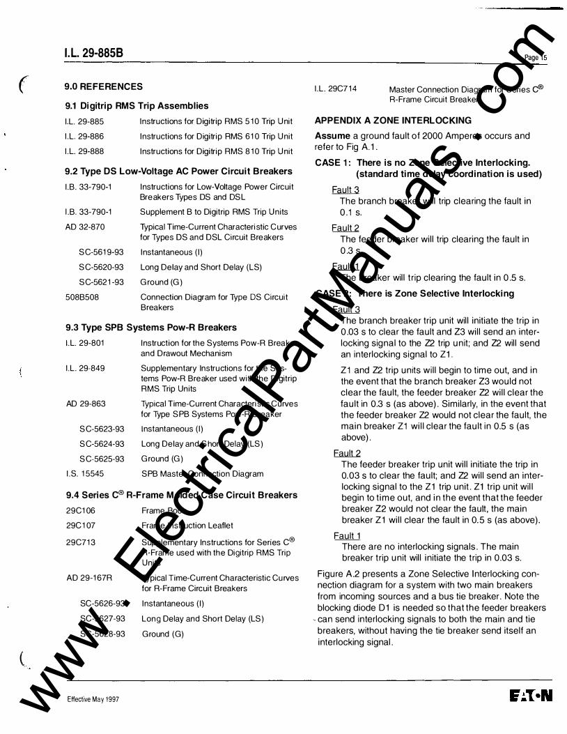
APPENDIX A ZONE INTERLOCKING
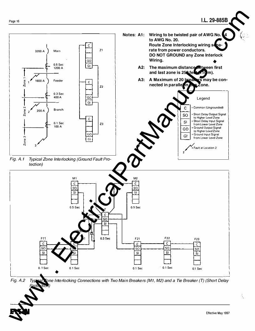
Assume a ground fault of 2000 Amperes occurs and refer to Fig A.1 .
CASE 1 : There is no Zone Selective Interlocking. (standard time delay coordination is used)
� T he branch breaker will trip clearing the fault in 0.1 s.
Fault 2 The feeder breaker will trip clearing the fault in 0.3 s.
Fault 1 The breaker will trip clearing the fault in 0.5 s.
CASE 2: There is Zone Selective Interlocking
Fault 3 The branch breaker trip unit will initiate the trip in 0.03 s to clear the fault and Z3 will send an interlocking signal to the Z2 trip unit; and Z2 will send an interlocking signal to Z1.
Z1 and Z2 trip units will begin to time out, and in the event that the branch breaker Z3 would not clear the fault, the feeder breaker Z2 will clear the fault in 0.3 s (as above). Similarly, in the event that the feeder breaker Z2 would not clear the fault, the main breaker Z1 will clear the fault in 0.5 s (as above).
Fault 2 T he feeder breaker trip unit will initiate the trip in 0.03 s to clear the fault; and Z2 will send an interlocking signal to the Z1 trip unit. Z1 trip unit will begin to time out, and in the event that the feeder breaker Z2 would not clear the fault, the main breaker Z1 will clear the fault in 0.5 s (as above).
Fault 1 There are no interlocking signals. T he main breaker trip unit will initiate the trip in 0.03 s.
Figure A.2 presents a Zone Selective Interlocking connection diagram for a system with two main breakers from incoming sources and a bus tie breaker. Note the blocking diode D1 is needed so that the feeder breakers
- can send interlocking signals to both the main and tie breakers, without having the tie breaker send itself an interlocking signal.
www . El
ectric
alPar
tMan
uals
. com
Page 16
I 3200 A ) M a i n Z 1
0.5 Sec
f 1 200 A
Q) 1 600 A ) Feeder g 1 N Z2
' 0.3 Sec
t 400 A
"' ) Q) 200 A Branch g 2 N
t-0. 1 Sec Z3 1 00 A
(") Q) c 0 N 3
Fig. A. 1 Typical Zone Interlockin g (Ground Fault Protection)
M 1
0 . 1 Sec 0 . 1 Sec
I .L. 29-8858
Notes: A1: Wiring to be twisted pair of AWG No. 1 4 to AWG No. 20. Route Zone Interlocking wiring sepa-rate from power conductors. DO NOT GROUND any Zone Interlock Wiring.
A2: The maximum distance between first and last zone is 250 feet (11 0 m).
A3: A Maximum of 20 breakers may be con-nected in parallel in one Zone.
Legend
= Common (Ungrounded)
= Short Delay Output Signal to Higher Level Zone
= Short Delay Input Signal from Lower Level Zone
= Ground Output Signal to Higher Level Zone
= Ground Input Signal from Lower Level Zone
/ault at Location 2 2
M2
0.5 Sec
F21 F22 F23
0 . 1 Sec 0. 1 Sec 0.1 Sec
Fig. A .2 Typical Zone Interlocking Connections with Two Main Breakers (M1, M2) and a Tie Breaker (T ) (Short Delay Protection)
Effective May 1997
(:
www . El
ectric
alPar
tMan
uals
. com
I .L. 29-8858 Page 17
( NOTES
Effective May 1997 www . El
ectric
alPar
tMan
uals
. com
Page 1 8 I .L. 29-8858
NOTES
Effective May 1997 www . El
ectric
alPar
tMan
uals
. com
I .L. 29-8858 Page 19
( ., . • '
'
0 . , NOTES
(
Effective May 1997 www . El
ectric
alPar
tMan
uals
. com
Page 20
This instruction booklet is published solely for information purposes and should not be considered all inclusive. If further information is required, you should consult Cutler-Hammer.
Sale of product shown in this literature is subject to terms and conditions outlined in appropriate Cutler-Hammer Inc. selling policies or other contractual agreement between the parties. This literature is not intended to and does not enlarge or add to any such contract. The sole source governing the rights and remedies of any purchaser of this equipment is the contract between the purchaser and Cutler-Hammer Inc.
NO WARRANTIES, EXPRESSED OR IMPLIED, INCLUDING WARRANTIES OF FITNESS FOR A PARTICULAR PURPOSE OR MERCHANTABILITY, OR WARRANTIES ARISING FROM COURSE OF DEALING OR USAGE OF TRADE, ARE MADE REGARDING THE IN FORMATION , RECOMMENDATIONS AND DESCRIPTIONS CONTAINED HEREIN. In no event will Cutler-Hammer Inc. be responsible to the purchaser or user in contract, in tort (including negligence), strict liability or otherwise for any special, indirect, incidental or consequential damage or loss whatsoever, including but not limited to damage or loss of use of equipment, plant or power system, cost of capital, loss of power, additional expenses in the use of existing power facilities, or claims against the purchaser or user by its customers resulting from the use of the information, recommendations and description contained herein.
Cutler-Hammer Inc Pittsburgh, Pennsylvania, U.S.A. Style No. 7829C35H03 Effective May 1997 Printed in U.S.A./CCI
I.L. 29-8858
www . El
ectric
alPar
tMan
uals
. com


![Cutler-Hammer Molded Case Circuit Breakers January 2001 Vol. 1, Ref. No. [0575] Molded Case Circuit Breakers 800 - 2500 Amperes 12-109 R-Frame 100% Rated Digitrip RMS 810 Circuit Breakers](https://static.fdocuments.in/doc/165x107/5ac0a7ec7f8b9a213f8c3d10/cutler-hammer-molded-case-circuit-breakers-january-2001-vol-1-ref-no-0575.jpg)