Cutler-Hammer Circuit Breakers and Trip Units G2-1 · PDF fileCircuit Breaker Components and...
64
January 1999 Cutler-Hammer CAT.71.01.T.E G2-1 G Circuit Breakers and Trip Units Molded Case Circuit Breakers General Description Page Circuit Breaker Components and Functions . . . . . . . . . . . . . . G2-2 Cutler-Hammer Family Molded Case Circuit Breakers . . . . . G2-2 Motor Circuit Protectors . . . . . . . . . . . . . . . . . . . . . . . . . . . . . . G2-3 Current Limiting Circuit Breakers . . . . . . . . . . . . . . . . . . . . . . G2-3 Special Application Breakers . . . . . . . . . . . . . . . . . . . . . . . . . . G2-3 World Standard Circuit Breakers . . . . . . . . . . . . . . . . . . . . . . . G2-4 Time Current Trip Curve Characteristics. . . . . . . . . . . . . . . . . G2-5 Selection Data Frame Reference Guide . . . . . . . . . . . . . . . . . . . . . . . . . . . . . . G2-6 Interrupting, Ampere, and Voltage Ratings . . . . . . . . . . . . . . G2-6 Quicklag ® Circuit Breaker Selection Data . . . . . . . . . . . . . . . . G2-9 240 Volt GFCI and Earth Leakage Breakers. . . . . . . . . . . . . . . G2-9 Quicklag Circuit Breaker Catalog Numbering System. . . . . . G2-11 Solenoid Operated, Remote-Controlled Breakers . . . . . . . . . G2-12 277 Volt Earth Leakage Breakers . . . . . . . . . . . . . . . . . . . . . . . G2-14 Series C Circuit Breaker Catalog Numbering System . . . . . . G2-15 Series C Circuit Breaker Selection Data . . . . . . . . . . . . . . . . . G2-16 Current Limiting Circuit Breaker Selection Data . . . . . . . . . . G2-24 Tri-Pac (Fused) Circuit Breaker Selection Data . . . . . . . . . . . . G2-25 Series C Motor Circuit Protector Selection Data . . . . . . . . . . G2-27 Electronic Trip Unit Selection Data . . . . . . . . . . . . . . . . . . . . . G2-32 Molded Case Circuit Breaker Accessories . . . . . . . . . . . . . . . G2-34 Application Information Page Voltage, Frequency, Continuous Amperes . . . . . . . . . . . . . . . G2-37 Cable Selection . . . . . . . . . . . . . . . . . . . . . . . . . . . . . . . . . . . . . G2-37 Circuit Breaker Sizing Considerations . . . . . . . . . . . . . . . . . . . G2-37 Motor Branch Circuits/Tables . . . . . . . . . . . . . . . . . . . . . . . . . . G2-38 Capacitor Protection/Tables . . . . . . . . . . . . . . . . . . . . . . . . . . . G2-39 Transformer Protection/Tables . . . . . . . . . . . . . . . . . . . . . . . . G2-40 Unusual Operating Conditions. . . . . . . . . . . . . . . . . . . . . . . . . G2-42 Circuit Breaker Temperatures, Ambient . . . . . . . . . . . . . . . . . G2-42 Altitude. . . . . . . . . . . . . . . . . . . . . . . . . . . . . . . . . . . . . . . . . . . . G2-42 Welding Applications . . . . . . . . . . . . . . . . . . . . . . . . . . . . . . . . G2-43 Mining Service Breakers . . . . . . . . . . . . . . . . . . . . . . . . . . . . . . G2-43 Engine Generator Breakers . . . . . . . . . . . . . . . . . . . . . . . . . . . G2-43 Molded Case Switches . . . . . . . . . . . . . . . . . . . . . . . . . . . . . . . G2-43 Dc Circuit Breakers . . . . . . . . . . . . . . . . . . . . . . . . . . . . . . . . . . G2-44 400-415 Hz Applications . . . . . . . . . . . . . . . . . . . . . . . . . . . . . . G2-45 100% Rated Breakers . . . . . . . . . . . . . . . . . . . . . . . . . . . . . . . . G2-47 Series Rated Systems . . . . . . . . . . . . . . . . . . . . . . . . . . . . . . . . G2-50 Series Combination Tables . . . . . . . . . . . . . . . . . . . . . . . . . . . G2-52 Typical Specifications Series C Circuit Breakers . . . . . . . . . . . . . . . . . . . . . . . . . . . . . G2-64 Replacement Circuit Breakers – Refer to Cutler-Hammer YES Catalog 26-000 Index
Transcript of Cutler-Hammer Circuit Breakers and Trip Units G2-1 · PDF fileCircuit Breaker Components and...

January 1999
Cutler-Hammer
CAT.71.01.T.E
G2-1
G
Circuit Breakers and Trip UnitsMolded Case Circuit Breakers
General Description
Page
Circuit Breaker Components and Functions . . . . . . . . . . . . . . G2-2Cutler-Hammer Family Molded Case Circuit Breakers . . . . . G2-2Motor Circuit Protectors . . . . . . . . . . . . . . . . . . . . . . . . . . . . . . G2-3Current Limiting Circuit Breakers . . . . . . . . . . . . . . . . . . . . . . G2-3Special Application Breakers . . . . . . . . . . . . . . . . . . . . . . . . . . G2-3World Standard Circuit Breakers . . . . . . . . . . . . . . . . . . . . . . . G2-4Time Current Trip Curve Characteristics. . . . . . . . . . . . . . . . . G2-5
Selection Data
Frame Reference Guide . . . . . . . . . . . . . . . . . . . . . . . . . . . . . . G2-6Interrupting, Ampere, and Voltage Ratings . . . . . . . . . . . . . . G2-6Quicklag
®
Circuit Breaker Selection Data . . . . . . . . . . . . . . . . G2-9240 Volt GFCI and Earth Leakage Breakers. . . . . . . . . . . . . . . G2-9Quicklag Circuit Breaker Catalog Numbering System. . . . . . G2-11Solenoid Operated, Remote-Controlled Breakers . . . . . . . . . G2-12277 Volt Earth Leakage Breakers . . . . . . . . . . . . . . . . . . . . . . . G2-14Series C Circuit Breaker Catalog Numbering System . . . . . . G2-15Series C Circuit Breaker Selection Data . . . . . . . . . . . . . . . . . G2-16Current Limiting Circuit Breaker Selection Data . . . . . . . . . . G2-24Tri-Pac (Fused) Circuit Breaker Selection Data. . . . . . . . . . . . G2-25Series C Motor Circuit Protector Selection Data . . . . . . . . . . G2-27Electronic Trip Unit Selection Data . . . . . . . . . . . . . . . . . . . . . G2-32Molded Case Circuit Breaker Accessories . . . . . . . . . . . . . . . G2-34
Application Information
Page
Voltage, Frequency, Continuous Amperes . . . . . . . . . . . . . . . G2-37Cable Selection . . . . . . . . . . . . . . . . . . . . . . . . . . . . . . . . . . . . . G2-37Circuit Breaker Sizing Considerations . . . . . . . . . . . . . . . . . . . G2-37Motor Branch Circuits/Tables. . . . . . . . . . . . . . . . . . . . . . . . . . G2-38Capacitor Protection/Tables . . . . . . . . . . . . . . . . . . . . . . . . . . . G2-39Transformer Protection/Tables . . . . . . . . . . . . . . . . . . . . . . . . G2-40Unusual Operating Conditions. . . . . . . . . . . . . . . . . . . . . . . . . G2-42Circuit Breaker Temperatures, Ambient . . . . . . . . . . . . . . . . . G2-42Altitude. . . . . . . . . . . . . . . . . . . . . . . . . . . . . . . . . . . . . . . . . . . . G2-42Welding Applications . . . . . . . . . . . . . . . . . . . . . . . . . . . . . . . . G2-43Mining Service Breakers. . . . . . . . . . . . . . . . . . . . . . . . . . . . . . G2-43Engine Generator Breakers . . . . . . . . . . . . . . . . . . . . . . . . . . . G2-43Molded Case Switches . . . . . . . . . . . . . . . . . . . . . . . . . . . . . . . G2-43Dc Circuit Breakers . . . . . . . . . . . . . . . . . . . . . . . . . . . . . . . . . . G2-44400-415 Hz Applications . . . . . . . . . . . . . . . . . . . . . . . . . . . . . . G2-45100% Rated Breakers . . . . . . . . . . . . . . . . . . . . . . . . . . . . . . . . G2-47Series Rated Systems . . . . . . . . . . . . . . . . . . . . . . . . . . . . . . . . G2-50Series Combination Tables . . . . . . . . . . . . . . . . . . . . . . . . . . . G2-52
Typical Specifications
Series C Circuit Breakers . . . . . . . . . . . . . . . . . . . . . . . . . . . . . G2-64
Replacement Circuit Breakers – Refer to Cutler-Hammer YES Catalog 26-000
Index
CAT.71.01.T.E
Cutler-Hammer
January 1999
G2-2
G
Circuit Breakers and Trip UnitsMolded Case Circuit Breakers
General Circuit Breaker Information
Cutler-Hammer molded case circuit breakers are designed to provide circuit protection for low voltage distribution systems. They are described by NEMA as, “. . . a device for clos-ing and interrupting a circuit between separa-ble contacts under both normal and abnormal conditions,” and further more as, “. . . a breaker assembled as an integral unit in a supporting and enclosing housing of insulat-ing material.” The NEC describes them as, “A device designed to open and close a circuit by non-automatic means, and to open the circuit automatically on a predetermined overload of current, without injury to itself when properly applied within its rating.”
So designed, Cutler-Hammer circuit breakers protect conductors against overloads and conductors and connected apparatus, such as motors and motor starters, against short circuits.
Circuit Breaker Components and Their Functions
Being essentially a high interrupting capacity switch with repetitive elements, Cutler-Ham-mer circuit breakers are comprised of three main functional components. These are: trip elements, operating mechanism and arc extinguishers.
Trip Elements
The function of the trip element is to trip the operating mechanism in the event of a prolonged overload or short circuit current. To accomplish this, a thermal-magnetic trip action is provided.
Thermal Magnetic Breakers
Thermal trip action is achieved through the use of a bimetal heated by the load current. On a sustained overload, the bimetal will deflect, causing the operating mechanism to trip. Because bimetals are responsive to the heat emitted by the current flow, they allow a long time delay on light overloads, yet they have a fast response on heavier overloads.
Magnetic trip action is achieved through the use of electro-magnet in series with the load current. This provides an instantaneous trip-ping action when the current reaches a prede-termined value. Front adjustable magnetic trip elements are supplied as standard on 250-amp frame Series C circuit breakers and above (except 100 and 150-amp magnetic only breakers), all other thermal magnetic breakers have non-adjustable magnetic trip elements.
Electronic RMS Trip Breakers
Both the overload trip action and the short cir-cuit trip action of breakers with Digitrip elec-tronic trip units are achieved by the use of current transformers and solid state circuitry that monitors the current and initiates trip-ping through a flux shunt trip when an
overload or short circuit is present. All multi-ple pole circuit breakers have trip elements in each pole and a common trip bar. An abnor-mal circuit condition in any one pole will cause all poles to open simultaneously.
Electronic rms trip breakers can include trip features such as:
●
Adjustable Long-Time Pickup
●
Adjustable Short-Time Pickup
●
Adjustable Short Delay Time
●
Adjustable Instantaneous Pickup
●
Adjustable Ground Fault Pickup
●
Adjustable Ground Fault Delay Time
●
Zone Selective Interlocking
●
Communications
Trip unit adjustments are made by setting switches on the front of the trip unit or by programming the trip unit electronically. All electronic rms trip breakers are equipped with a manual push-to-trip mechanism.
Operating Mechanism
The function of the operating mechanism is to provide a means of opening and closing the breaker contacts. All Mechanisms are of the quick-make, quick-break type and are “trip free.” “Trip free” mechanisms are designed so that the contacts cannot be held closed against an abnormal circuit condition and are sometimes referred to as an “overcenter tog-gle mechanism.” In addition to indicating whether the breaker is “on” or “off,” the oper-ating mechanism handle indicates when the breaker is “tripped” by moving to a position midway between the extremes. This distinct trip point is particularly advantageous where breakers are grouped, as in panelboard appli-cations, because it clearly indicates the faulty circuit. The operating mechanism contains a positive on feature. In the normal switching operation, the handle of the circuit breaker shall not be capable of being left readily at or near the off position when the main contacts are closed.
Arc Extinguishers
The function of the DE-ION arc extinguisher is to confine, divide and extinguish the arc drawn between opening breaker contacts. It consists of specially shaped steel grids iso-lated from each other and supported by an insulating housing. When the contacts are opened, the arc drawn induces a magnetic field in the grids, which in turn draws the arc from the contacts and into the grids. The arc is thus split into a series of smaller arcs and the heat generated is quickly dissipated through the metal. These two actions result in a rapid removal of ions from the arc, which hastens dielectric build-up between the con-tacts and results in rapid extinction of the arc.
Cutler-Hammer Family Molded Case Circuit Breakers
In low voltage distribution systems, there are many varied applications of molded case
circuit breakers. Cutler-Hammer offers the most comprehensive family of molded case circuit breakers in the industry.
This family of circuit breakers includes:
●
Thermal Magnetic Trip Breakers
●
Electronic rms Trip Breakers
●
Molded Case Switches
●
Motor Circuit Protectors
●
Current Limiting Breakers
●
Special Application Breakers
●
World Breakers
Thermal Magnetic Trip Breaker
Thermal magnetic breakers are general purpose devices suitable for the majority of breaker applications and are considered the industry standard. Available from 15 through 800 amperes, thermal magnetic breakers provide accurate reliable overload and short circuit protection for conductors and connected apparatus.
Electronic Trip Breakers
Electronic trip breakers are generally applied for applications where high levels of system coordination are called for. Available from 70 through 2500 amperes, today’s electronic trip breakers can provide superior protection and coordination as well as system alarms and di-agnostics, monitoring and communications.
Interrupting Ratings
Molded case circuit breakers are available in various interrupting capacities. Standard interrupting capacity breakers are available in both industrial and replacement circuit breaker lines. These breakers have interrupt-ing capacities up to 35 kA at 480 Vac.
High interrupting capacity breakers are simi-lar to standard interrupting capacity breakers, but the improved performance makes these breakers suited for use in today’s network systems where higher fault currents exist. These breakers have interrupting capacities up to 65 kA at 480 Vac.
For applications that call for very high inter-rupting ratings current limiting high inter-rupting capacity breaker are available. These breakers offer true current limiting character-istics in the same physical frame size as the high interrupting capacity version and have interrupting capacities of 100 kA at 480 Vac.
Molded Case Switches
Molded case switches are UL 1087 devices that have no thermal protection but do have a self protecting high magnetic trip setting. Molded case switches are applied when a compact high capacity disconnect device is called for. Accessories that can be installed in molded case circuit breakers are also avail-able for molded case switches. The most common application for a molded case switch would be as a main disconnect for a panelboard or a loadcenter. Available from 100 through 2500 amperes, molded case switches provided a compact disconnect
General Description

January 1999
Cutler-Hammer
CAT.71.01.T.E
G2-3
G
Circuit Breakers and Trip UnitsMolded Case Circuit Breakers
device along with the added benefits of a molded case circuit breaker without the thermal protection.
Motor Circuit Protectors
Application flexibility of Series C Motor Circuit Protectors (Type GMCP/HMCP) is enhanced by the higher interrupting ratings and current limiting characteristics designed into the Series C line. These devices are avail-able from 3-600 amperes in 63, 100, 150, 250, 400, and 600 A-frame sizes.
The Type GMCP/HMCP is designed for appli-cation in individual motor circuits in combina-tion motor starter units. GMCP/HMCPs operate on the magnetic principle with a cur-rent sensing element in each pole to provide short circuit protection.
The Series C Type GMCP/HMCP design per-mits the most effective protection possible against low-level faults while offering circuit breaker convenience, quick make-quick break action, dead front safety, and prevention of single phasing.
Current Limiting Circuit Breakers
Cutler-Hammer offers one of the most complete lines of both fusible and non-fused current limiting breakers in the industry. The Series C industrial breakers are available in current limiting versions with interrupting capacities up to 100 kA at 480V without fuses in the same physical size as standard and high interrupting capacity breakers. Cutler-Hammer also manufactures both fused and non-fused current limiting devices with interrupting capacities up to 200 kA at 600 Vac.
Series C Current Limiting Breakers
The Series C current limiting breakers utilizea reverse loop stationary contact. When current is flowing through the contacts of these breakers, the positions of the reverse loop and moving contact arm induce oppos-ing magnetic fields. The resulting flux lines cause rapid contact blow apart under these conditions resulting in very high interrupting capacities and provide current limiting characteristics.
Series C current limiting breakers are available from 15 through 2500 amperes and have an interrupting rating of 100 kA at 480 volts. These breakers are most commonly applied when very high (up 100 kA) fault levels are available and in series rating applications where the current limiting capability of these breakers are used upsteam in series combinations.
Series C circuit breakers which are current limiting have frame catalog numbers which end with the letter "C." For example, the F-frame model which is current limiting has a catalog number FDC. In accordance with UL circuit breaker marking requirements, the nameplate on the breaker is also labeled "current limiting."
Current Limit-R Breakers
The Current Limit-R molded case circuit breaker was developed with interrupting ratings up to 200,000 amperes at 480 Vac, to provide complete system protection against faults, including:
1. Overloads, by using inverse time current tripping characteristics;
2. Low-level short circuits, by using instanta-neous and/or short time delay tripping characteristics;
3. High-level short circuits, by using ultra high-speed, blow apart, current limiting contacts.
Current Limit-R circuit breakers can be used in series with Cutler-Hammer standard molded case circuit breakers with listed interrupting ratings as low as 10,000 amperes in systems capable of delivering fault currents as high as 200,000 amperes. The excellent current limit-ing properties of the Current Limit-R breakers completely protect all Cutler-Hammer down-stream series circuit breakers applied within their voltage ratings.
The high level current-limiting action is achieved by the use of special design, blow-apart contacts. The opening speed of the contacts is amplified by the repulsion force in the patented slot motor to effectively separate the contacts under high level fault conditions in less than one millisecond. The rapid rise of arc voltage introduces impedance into the system, thus limiting the amount of the other-wise available fault current.
The Current Limit-R current limiting circuit breakers incorporate all the advantages and features of conventional molded case circuit breakers. They are available in two- and three-pole versions in two physical frame sizes and three continuous current frame ratings.
The Type FCL has maximum continuous cur-rent frame rating of 100 amperes. It is equipped with a conventional, non-interchangeable, thermal magnetic-type trip unit with individual ampere ratings. The Type LCL is available with frames having maximum continuous current ratings of either 250 or 400 amperes . Overload and low level short circuit protection is pro-vided by a SELTRONIC electronic trip unit which uses the individual rating plug concept for determining the continuous rating of the breaker. Rating plugs are available with either fixed or adjustable ampere ratings.
TRI-PAC Breakers
The increase in demand for electrical power in modern commercial and industrial buildings has resulted in electrical services becoming substantially larger. In some low voltage distri-bution systems, available short circuit currents can exceed 100,000 symmetrical rms am-peres. Fault currents of this intensity may ex-ceed the interrupting ratings of molded case breakers. As a result, larger expensive circuit
interrupting devices which could withstand the thermal and magnetic stresses associated with currents of this value have had to be used. High interrupting capacity current limit-ing devices have been developed which will restrict short circuit current. If applied correct-ly, they may be used in conjunction with the molded case circuit breakers to provide ade-quate and economical protection.
The TRI-PAC breaker was developed for this application and so named because it affords TRIple-PACkage protection with (1) time delay thermal trip, (2) instantaneous magnetic trip and (3) current limiting protection, combined and coordinated in a compact and economical device. These protective actions are so coordi-nated that overcurrents and low magnitude faults are cleared by the thermal action; nor-mal short circuits are cleared by the magnetic action; and abnormal short circuits, above an established value, are cleared by the current limiting device. Thus, unless a severe short circuit occurs, the current limiter is unaffected and its replacement is held to a minimum.
TRI-PAC breakers are available in ratings from 15 through 1600 amperes and have a U/L listed interrupting capacity of 200,000 amperes at up to 600 volts ac and also have an interrupting capacity of 100,000 amperes at up to 250 volts dc.
The TRI-PAC breaker offers all of the advan-tages of the economical molded case breaker and the current limiter are retained, while the disadvantages of separately mounted devic-es are eliminated.
Special Application Breakers
Cutler-Hammer offer a wide range of special application molded case circuit breakers. Special application breakers are breakers built with special features to meet the unique requirements of the special application as follows. See the application data section for further information.
Dc Rated Breakers
Dc rated breakers are available for use with ungrounded applications where all three poles are connected in series. Rated for up to 600 Vdc breakers are available from15-2500 ampere trip ranges with thermal magnetic trip units or special low magnetic only trip devices. Their compact size and increased interrupting performance give Cutler-Hammer the most complete range of dc breakers in the industry.
Mining Breakers
Cutler-Hammer mining circuit breakers have a tradition of proven dependability and reli-ability in harsh mine environments, consis-tently combining strength and reliability with safe, efficient operation. The E
2
G mining breaker is available in 225 and 400 ampere frames and is designed for trailing cable applications per MSHA 30 CFR 75. With inter-rupting ratings of 14 kA at 1000/577 Vac and
General Description
CAT.71.01.T.E
Cutler-Hammer
January 1999
G2-4
G
Circuit Breakers and Trip UnitsMolded Case Circuit Breakers
rms sensing electronic trip unit the E
2
G mining breaker can be applied to all mining circuit breaker applications.
Navy/Marine Circuit Breakers
Molded case Navy circuit breakers provide both overload protection for conductors and short circuit protection for all circuit elements such as conductors, motors and starters. They also serve as manual disconnecting means as well as circuit protectors. All Cutler-Hammer Navy breakers meet applicable Navy/Marine specifications for “hi-shock” and “vibration” requirements. These manually operated breakers are rated from 5 to1600 amperes with interrupting ratings from 1,500 to 100,000 amperes.
Lighting and Industrial Breakers
Recognizing the growing need for high inter-rupting requirements on 240V applications such as loadcenters, metercenters, metering switchboards, distribution switchboards and panelboards, etc. the Cutler-Hammer family of lighting and industrial circuit breakers is designed to meet all applications. The Cutler-Hammer family of Quicklag miniature circuit breakers are available in bolt-on, plug-in and cable-in cable-out configurations. For molded case circuit breakers, Cutler-Hammer offers the GB/GC design up through 100 amperes and the ED/EDH/EDC design up through 225 amperes up to 200 kA at 240 volts.
HACR Listed Circuit Breakers
HACR listed circuit breakers are circuit break-ers that have been tested per UL for use in heating, air conditioning and refrigeration applications. HACR type circuit breakers are typically applied as the protection device for multimotor or combination loads in a group installation configuration. Cutler-Hammer has its family of Quicklag QC miniature break-ers and Series C molded case breaker frames G, F, J and K listed for HACR applications.
Engine Generator Circuit Breakers
Engine generator circuit breakers are designed specifically for application on diesel engine powered standby generator systems. Generator breakers are equipped with a spe-cial trip unit that provides standard overload protection with low magnetic short circuit protection to suit generator applications that call for close short circuit protection at low interrupting ratings.
Cutler-Hammer offers a family of engine generator circuit breakers in six frames from 15 to 1200 amperes that conform to UL, CSA and IEC standards.
100% Rated Circuit Breakers
100% rated circuit breakers are tested inside a minimum size enclosure to UL 489 for appli-cation at 100% of the breakers continuous current rating. 100% rated circuit breakers are equipped with electronic trip units and applied with 90C cable rated at 75C ampacity. To apply 100% rated breakers in switch-boards and panelboards additional tests are required to meet UL 67 and UL 891. Cutler-Hammer Series C molded case circuit breaker frames K-, L-, N- and R-, 70 through 2000 amperes can be applied at 100% of their rated continuous current as long as the breaker is installed in its minimum size enclosure including ventilation. 100% rated breakers are applied to distribution system to provide installation cost savings. The amount of savings that can be realized is dependent on the application.
Series Rating Circuit Breakers
Series rating is a short circuit interrupting rating assigned to a combination of two or more overcurrent devices connected in series. The short circuit interrupting rating of the upstream device must be equal to or greater than the available fault current. Downstream breakers, however, are not fully rated for the system’s available fault current. Series combi-nations must be tested to UL 489. Series ratings are applied to distribution systems where short circuit coordination is not required. Cutler-Hammer listing of available series rating combinations are shown in the applications section of this document.
World Standard Circuit Breakers (IEC947-2)
Series C molded case circuit breakers meet all major electrical standards of the world. There are two branches of the Series C family tree. One meets applicable UL, NEMA, CSA and IEC standards and employs a fixed ther-mal and fixed or adjustable magnetic trip. The second meets IEC 947-2 and has been assigned ultimate and service interrupting ratings, and employs adjustable thermal and adjustable magnetic trips. The frame ratings of both types of breakers are physically inter-changeable with each other. Cutler-Hammer is the first manufacturer in the industry to have a true family of world circuit breakers.
Standards
●
Canadian Standards Association Standard C22.2 No. 5, Service Entrance and Branch Circuit Breakers
●
National Electrical Manufacturers Association Standards Publication Number AB1, Molded Case Circuit Breakers
●
Underwriters Laboratories, Inc. Standard UL 489, Molded Case Circuit Breakers and Circuit Breaker Enclosures, including Marine Circuit Breakers File E7819
●
Underwriters Laboratories, Inc. Standard UL 1087, Molded Case Switches
General Description
Further Information
PG.74A.01.T.ESA.74A.01.T.ECAT.73.01.T.E
January 1999
Cutler-Hammer
CAT.71.01.T.E
G2-5
G
Circuit Breakers and Trip UnitsMolded Case Circuit Breakers
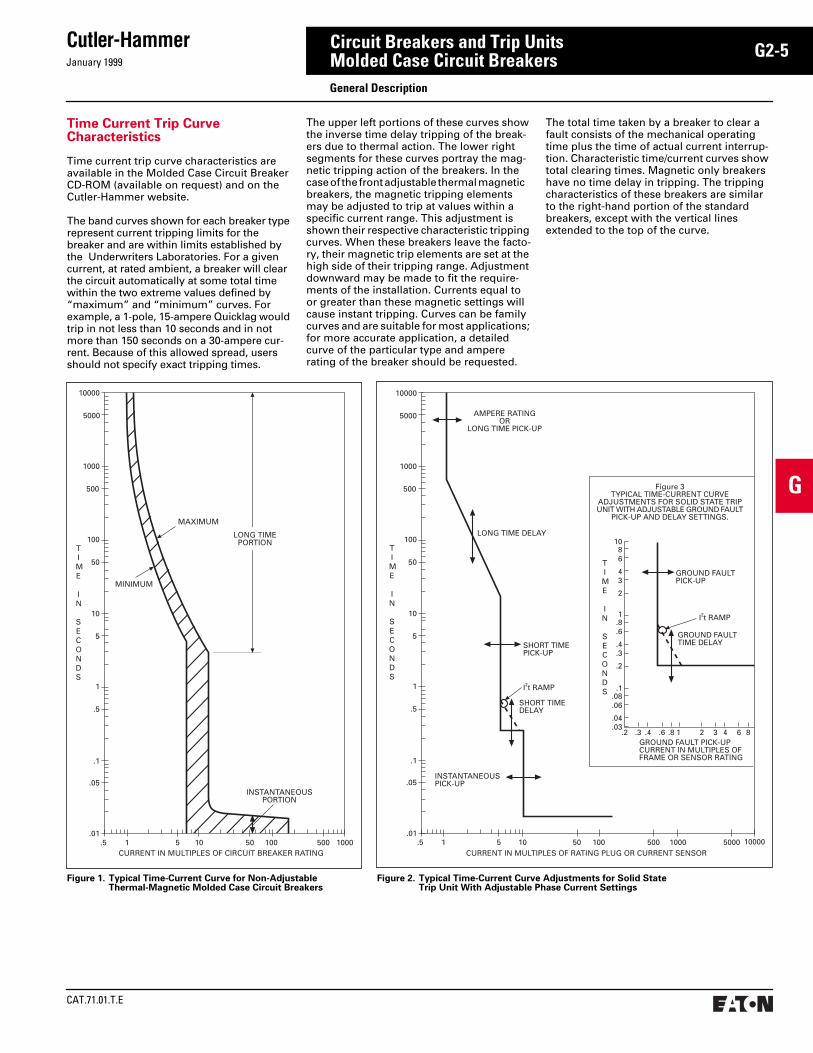
Time Current Trip Curve Characteristics
Time current trip curve characteristics are available in the Molded Case Circuit Breaker CD-ROM (available on request) and on the Cutler-Hammer website.
The band curves shown for each breaker type represent current tripping limits for the breaker and are within limits established by the Underwriters Laboratories. For a given current, at rated ambient, a breaker will clear the circuit automatically at some total time within the two extreme values defined by “maximum” and “minimum” curves. For example, a 1-pole, 15-ampere Quicklag would trip in not less than 10 seconds and in not more than 150 seconds on a 30-ampere cur-rent. Because of this allowed spread, users should not specify exact tripping times.
The upper left portions of these curves show the inverse time delay tripping of the break-ers due to thermal action. The lower right segments for these curves portray the mag-netic tripping action of the breakers. In the case of the front adjustable thermal magnetic breakers, the magnetic tripping elements may be adjusted to trip at values within a specific current range. This adjustment is shown their respective characteristic tripping curves. When these breakers leave the facto-ry, their magnetic trip elements are set at the high side of their tripping range. Adjustment downward may be made to fit the require-ments of the installation. Currents equal to or greater than these magnetic settings will cause instant tripping. Curves can be family curves and are suitable for most applications; for more accurate application, a detailed curve of the particular type and ampere rating of the breaker should be requested.
Figure 1. Typical Time-Current Curve for Non-AdjustableThermal-Magnetic Molded Case Circuit Breakers
The total time taken by a breaker to clear a fault consists of the mechanical operating time plus the time of actual current interrup-tion. Characteristic time/current curves show total clearing times. Magnetic only breakers have no time delay in tripping. The tripping characteristics of these breakers are similar to the right-hand portion of the standard breakers, except with the vertical lines extended to the top of the curve.
CURRENT IN MULTIPLES OF CIRCUIT BREAKER RATING
INSTANTANEOUSPORTION
.5 1 5 10 50 100 500 1000.01
.05
.1
.5
1
5
10
50
100
500
1000
5000
10000
LONG TIMEPORTION
MAXIMUM
MINIMUM
TIME
IN
SECONDS
INSTANTANEOUSPICK-UP
LONG TIME DELAY
CURRENT IN MULTIPLES OF RATING PLUG OR CURRENT SENSOR.5 1 5 10 50 100 500 1000
.015000 10000
.05
.1
.5
1
5
10
50
100
500
1000
5000
10000
TIME
IN
SECONDS
SHORT TIMEDELAY
SHORT TIMEPICK-UP
AMPERE RATINGOR
LONG TIME PICK-UP
GROUND FAULT PICK-UPCURRENT IN MULTIPLES OFFRAME OR SENSOR RATING
.2 .3 .4 .6 .8 1 2 3 4 6 8
.2
.3
.4
.6
.81
.03
.04
.06
.08.1
2
34
68
10
GROUND FAULTTIME DELAY
I2t RAMP
GROUND FAULTPICK-UP
TIME
IN
SECONDS
Figure 3TYPICAL TIME-CURRENT CURVE
ADJUSTMENTS FOR SOLID STATE TRIPUNIT WITH ADJUSTABLE GROUND FAULT
PICK-UP AND DELAY SETTINGS.
I2t RAMP
Figure 2. Typical Time-Current Curve Adjustments for Solid State Trip Unit With Adjustable Phase Current Settings
General Description

CAT.71.01.T.E
Cutler-Hammer
January 1999
G2-6
G
Circuit Breakers and Trip UnitsMolded Case Circuit Breakers
Circuit Breaker Frame Reference Guide
Frame NominalSizeAmperes
CircuitBreakerTypes
Q or B 5-125 HQP, QPHW, QHPX, QHPW, QPGF, QPHGF, QPGFEP, QPHGFEP, BAB, QBHW, HBAX, HBAW, QBGF, QBHGF, QBGFEP, QBHGFEP, QC, QCF, QCR, QCHW, QHCX, QHCW, QCGF, QCHGF, QCGFEP, QCHGFEP
G 15-100 GB, GHB, GHBS, GC, GHC, GD
E 100-225 ED, EDH, EDC, EHD (100 amp)
F 15-150 FDB, FD, HFD, FDC
J 70-250 JDB, JD, HJD, JDC
K 70-400 KDB, KD, CKD, HKD, CHKD, KDC
L 300-600 LDB, LD, CLD, HLD, CHLD, LDC, CLDC
M 400-800 MDLB, MDL, CMDL, HMDLB, HMDL, CHMDL
N 600-1200 ND, CND, HND, CHND, NDC, CNDC
R 800-2500 RD, CRD, RDC, CRDC
Series C Industrial Circuit Breakers – Standard, High Interrupting Capacity, and Current Limiting
CircuitBreakerType
Cont.AmpereRatingAt 40°C
NumberofPoles
Volts Type of Trip
➀
FederalSpec.W-C-375b
UL Listed Interrupting Ratings rms Symmetrical Amperes
➁
Ac Dc Ac Ratings Volts Dc
➂
120 240 277 480 600 125 250
EDEDHEDC
➃
100-225100-225100-225
2, 32, 32, 3
240240240
125125125
N.I.T. 12b14b1
. . . .
. . . .
. . . .
65,000100,000200,000
. . . . . . . . . . . .
. . . .
. . . .
. . . .
. . . .
. . . .
. . . .
10,00010,00010,000
. . . .
. . . .
. . . .
GDGD
15-100 15-100
12, 3
480480
. . . . N.I.T. 13b 65,000. . . .
. . . . 65,000
22,000. . . .
. . . .22,000
. . . .
. . . .10,000
. . . .. . . .
10,000
EHDEHD
15-100 15-100
12, 3
277480
125250
N.I.T. 13a13b
. . . .
. . . .. . . .
18,00014,000
. . . .. . . .
14,000. . . .. . . .
10,000. . . .
. . . .10,000
FDBFDB
15-150 15-150
2, 34
600600
250250
N.I.T. 18a
➄
. . . .
. . . .18,00018,000
. . . . . . . .
14,00014,000
14,00014,000
. . . .
. . . .10,00010,000
FDFDFD
15-150 15-225 15-225
12, 34
277600600
125250250
N.I.T. 13a22a
➄
. . . .
. . . .
. . . .
. . . .65,00065,000
25,000 . . . . . . . .
. . . .25,00025,000
. . . .18,00018,000
10,000. . . .. . . .
. . . .10,00010,000
HFDHFDHFD
15-150 15-225 15-225
12, 34
277600600
125250250
N.I.T. 13a23a
➄
. . . .
. . . .
. . . .
. . . .100,000100,000
65,000 . . . . . . . .
. . . .65,00065,000
. . . .25,00025,000
10,000. . . .. . . .
. . . .22,00022,000
FDC
➃
FDC
➃
15-225 15-225
2, 34
600600
250250
N.I.T. 24a
➄
. . . .
. . . .200,000200,000
. . . . . . . .
100,000100,000
35,00035,000
. . . .
. . . .22,00022,000
JDBJDHJDJDC
➃
70-250 70-250 70-250 70-250
2, 32, 3, 42, 3, 42, 3, 4
600600600600
250250250250
N.I.T.I.T.I.T.I.T.
22a22a22a22a
. . . .
. . . .
. . . .
. . . .
65,00065,000
100,000200,000
. . . . . . . . . . . . . . . .
25,00025,00065,000
100,000
18,00018,00025,00035,000
. . . .
. . . .
. . . .
. . . .
10,00010,00022,00022,000
DK 250-400 2, 3 240 250 N.I.T. 14b . . . . 65,000 . . . . . . . . . . . . . . . . 10,000
KDBKDCKD
➅
HKDCHKD
➅
KDC
➃
70-400 70-400 70-400 70-400 70-400 70-400
2, 32, 3, 42, 3, 42, 3, 42, 3, 42, 3, 4
600600600600600600
250250250250250250
N.I.T.I.T.I.T.I.T.I.T.I.T.
23a23a23a23a23a23a
. . . .
. . . .
. . . .
. . . .
. . . .
. . . .
65,00065,00065,000
100,000100,000200,000
. . . . . . . . . . . . . . . . . . . . . . . .
35,00035,00035,00065,00065,000
100,000
25,00025,00025,00035,00035,00050,000
. . . .
. . . .
. . . .
. . . .
. . . .
. . . .
10,00010,00010,00022,00022,00022,000
LDBLDCLD
➅
HLDCHLD
➅
LDC
➃
CLDC
➃➅
300-600300-600300-600300-600300-600300-600300-600
2, 32, 3, 42, 3, 42, 3, 42, 3, 42, 3, 42, 3, 4
600600600600600600600
250250. . . .250. . . .250. . . .
N.I.T.I.T.I.T.I.T.I.T.I.T.I.T.
23a23a23a23a23a23a23a
. . . .
. . . .
. . . .
. . . .
. . . .
. . . .
. . . .
65,00065,00065,000
100,000100,000200,000200,000
. . . . . . . . . . . . . . . . . . . . . . . . . . . .
35,00035,00035,00065,00065,000
100,000100,000
25,00025,00025,00035,00035,00050,00050,000
. . . .
. . . .
. . . .
. . . .
. . . .
. . . .
. . . .
22,00022,000
. . . .25,000
. . . .25,000
. . . .
MDLBMDLCMDL
➅
HMDLBHMDLCHMDL
➅
300-800300-800300-800300-800300-800300-800
2, 32, 32, 32,32, 32, 3
600600600600600600
250250. . . .250250. . . .
N.I.T.I.T.I.T.N.I.T.I.T.I.T.
. . . .
. . . .
. . . .
. . . .
. . . .
. . . .
. . . .
. . . .
. . . .
. . . .
. . . .
. . . .
65,00065,00065,000
100,000100,000100,000
. . . . . . . . . . . . . . . . . . . .
50,00050,00050,00065,00065,00065,000
25,00025,00025,00035,00035,00035,000
. . . .
. . . .
. . . .
. . . .
. . . .
. . . .
22,00022,000
. . . .25,00025,000
. . . .
➀
N.I.T. is non-interchangeable trip unit and I.T. is interchangeable trip unit.
➁
Refer to Series C Selection Data for any IEC ratings.
➂
Two-pole circuit breaker, or two poles of three-pole circuit breaker at 250 Vdc.
➃
Current limiting.
➄
Not defined in W-C-375b.
➅
100% rated.
Circuit Breaker Selection Guide and Interrupting Ratings
January 1999
Cutler-Hammer
CAT.71.01.T.E
G2-7
G
Circuit Breakers and Trip UnitsMolded Case Circuit Breakers
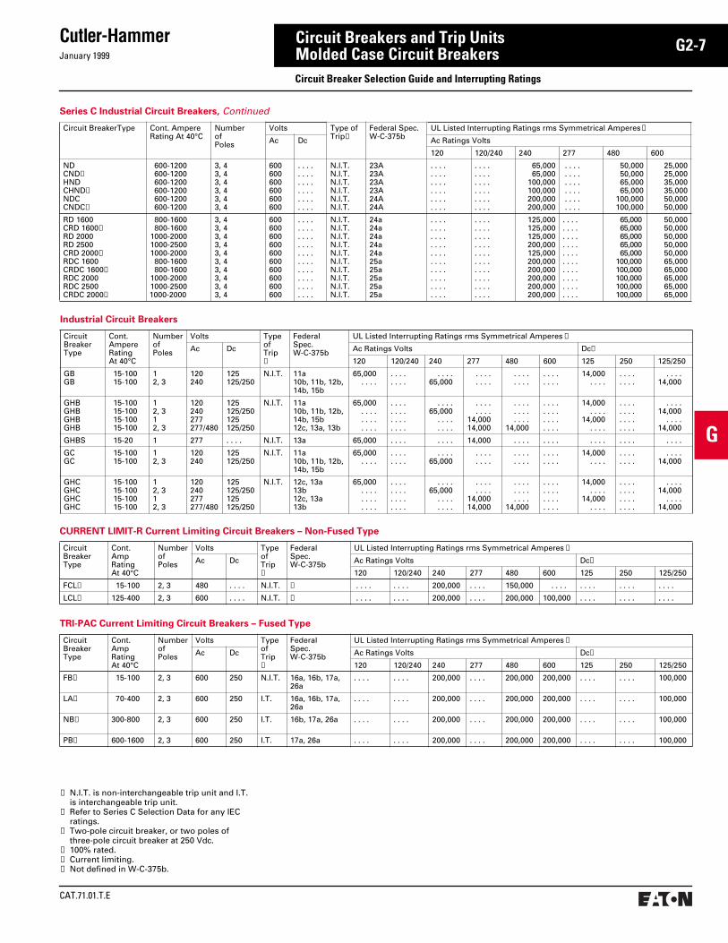
Industrial Circuit Breakers
CircuitBreakerType
Cont.AmpereRatingAt 40°C
NumberofPoles
Volts Type of Trip
➀
FederalSpec.W-C-375b
UL Listed Interrupting Ratings rms Symmetrical Amperes
➁
Ac Dc Ac Ratings Volts Dc
➂
120 120/240 240 277 480 600 125 250 125/250
GBGB
15-100 15-100
12, 3
120240
125125/250
N.I.T. 11a10b, 11b, 12b, 14b, 15b
65,000. . . .
. . . .
. . . .. . . .
65,000. . . .. . . .
. . . .
. . . .. . . . . . . .
14,000. . . .
. . . .
. . . . . . . .
14,000
GHBGHBGHBGHB
15-100 15-100 15-100 15-100
12, 312, 3
120240277277/480
125125/250125125/250
N.I.T. 11a10b, 11b, 12b, 14b, 15b12c, 13a, 13b
65,000. . . .. . . .. . . .
. . . .
. . . .
. . . .
. . . .
. . . .65,000
. . . .
. . . .
. . . .
. . . .14,00014,000
. . . .
. . . .
. . . .14,000
. . . .
. . . .
. . . .
. . . .
14,000. . . .
14,000. . . .
. . . .
. . . .
. . . .
. . . .
. . . .14,000
. . . .14,000
GHBS 15-20 1 277 . . . . N.I.T. 13a 65,000 . . . . . . . . 14,000 . . . . . . . . . . . . . . . . . . . .
GCGC
15-100 15-100
12, 3
120240
125125/250
N.I.T. 11a10b, 11b, 12b, 14b, 15b
65,000. . . .
. . . .
. . . . . . . .
65,000. . . .. . . .
. . . .
. . . .. . . . . . . .
14,000. . . .
. . . .
. . . . . . . .
14,000
GHCGHCGHCGHC
15-100 15-100 15-100 15-100
12, 312, 3
120240277277/480
125125/250125125/250
N.I.T. 12c, 13a13b12c, 13a13b
65,000. . . .. . . .. . . .
. . . .
. . . .
. . . .
. . . .
. . . .65,000
. . . .
. . . .
. . . .
. . . .14,00014,000
. . . .
. . . .
. . . .14,000
. . . .
. . . .
. . . .
. . . .
14,000. . . .
14,000. . . .
. . . .
. . . .
. . . .
. . . .
. . . .14,000
. . . .14,000
➀
N.I.T. is non-interchangeable trip unit and I.T. is interchangeable trip unit.
➁
Refer to Series C Selection Data for any IECratings.
➂
Two-pole circuit breaker, or two poles of three-pole circuit breaker at 250 Vdc.
➃
100% rated.
➄
Current limiting.
➅
Not defined in W-C-375b.
Series C Industrial Circuit Breakers,
Continued
Circuit BreakerType Cont. AmpereRating At 40°C
NumberofPoles
Volts Type ofTrip
➀
Federal Spec.W-C-375b
UL Listed Interrupting Ratings rms Symmetrical Amperes
➁
Ac Dc Ac Ratings Volts
120 120/240 240 277 480 600
NDCND
➃
HNDCHND
➃
NDCCNDC➃
600-1200 600-1200 600-1200 600-1200 600-1200 600-1200
3, 43, 43, 43, 43, 43, 4
600600600600600600
. . . .
. . . .
. . . .
. . . .
. . . .
. . . .
N.I.T.N.I.T.N.I.T.N.I.T.N.I.T.N.I.T.
23A23A23A23A24A24A
. . . .
. . . .
. . . .
. . . .
. . . .
. . . .
. . . .
. . . .
. . . .
. . . .
. . . .
. . . .
65,00065,000
100,000100,000200,000200,000
. . . . . . . . . . . . . . . . . . . . . . . .
50,00050,00065,00065,000
100,000100,000
25,00025,00035,00035,00050,00050,000
RD 1600CRD 1600➃RD 2000RD 2500CRD 2000➃RDC 1600CRDC 1600➃RDC 2000RDC 2500CRDC 2000➃
800-1600800-1600
1000-20001000-25001000-2000
800-1600800-1600
1000-20001000-25001000-2000
3, 43, 43, 43, 43, 43, 43, 43, 43, 43, 4
600600600600600600600600600600
. . . .
. . . .
. . . .
. . . .
. . . .
. . . .
. . . .
. . . .
. . . .
. . . .
N.I.T.N.I.T.N.I.T.N.I.T.N.I.T.N.I.T.N.I.T.N.I.T.N.I.T.N.I.T.
24a24a24a24a24a25a25a25a25a25a
. . . .
. . . .
. . . .
. . . .
. . . .
. . . .
. . . .
. . . .
. . . .
. . . .
. . . .
. . . .
. . . .
. . . .
. . . .
. . . .
. . . .
. . . .
. . . .
. . . .
125,000125,000125,000200,000125,000200,000200,000200,000200,000200,000
. . . .
. . . .
. . . .
. . . .
. . . .
. . . .
. . . .
. . . .
. . . .
. . . .
65,00065,00065,00065,00065,000
100,000100,000100,000100,000100,000
50,00050,00050,00050,00050,00065,00065,00065,00065,00065,000
CURRENT LIMIT-R Current Limiting Circuit Breakers – Non-Fused Type
TRI-PAC Current Limiting Circuit Breakers – Fused Type
CircuitBreakerType
Cont.AmpRatingAt 40°C
NumberofPoles
Volts Type of Trip➀
FederalSpec.W-C-375b
UL Listed Interrupting Ratings rms Symmetrical Amperes ➁
Ac Dc Ac Ratings Volts Dc➂
120 120/240 240 277 480 600 125 250 125/250
FCL➄ 15-100 2, 3 480 . . . . N.I.T. ➅ . . . . . . . . 200,000 . . . . 150,000 . . . . . . . . . . . . . . . .
LCL➄ 125-400 2, 3 600 . . . . N.I.T. ➅ . . . . . . . . 200,000 . . . . 200,000 100,000 . . . . . . . . . . . .
CircuitBreakerType
Cont.AmpRatingAt 40°C
NumberofPoles
Volts Type of Trip➀
FederalSpec.W-C-375b
UL Listed Interrupting Ratings rms Symmetrical Amperes ➁
Ac Dc Ac Ratings Volts Dc➂
120 120/240 240 277 480 600 125 250 125/250
FB➄ 15-100 2, 3 600 250 N.I.T. 16a, 16b, 17a,26a
. . . . . . . . 200,000 . . . . 200,000 200,000 . . . . . . . . 100,000
LA➄ 70-400 2, 3 600 250 I.T. 16a, 16b, 17a,26a
. . . . . . . . 200,000 . . . . 200,000 200,000 . . . . . . . . 100,000
NB➄ 300-800 2, 3 600 250 I.T. 16b, 17a, 26a . . . . . . . . 200,000 . . . . 200,000 200,000 . . . . . . . . 100,000
PB➄ 600-1600 2, 3 600 250 I.T. 17a, 26a . . . . . . . . 200,000 . . . . 200,000 200,000 . . . . . . . . 100,000
Circuit Breaker Selection Guide and Interrupting Ratings

CAT.71.01.T.E
Cutler-HammerJanuary 1999
G2-8
G
Circuit Breakers and Trip UnitsMolded Case Circuit Breakers
Circuit Breaker Type Codes: P Plug-in; B Bolt-on; C Cable-in/Cable-out; GF Ground Fault, 5 ma; GFEP Ground Fault, 30 ma.
Quicklag Industrial Circuit Breakers➀
Plug-in, Bolt-on, Cable-in/Cable-out
CircuitBreakerType
Circuit Breaker Type Code
Cont.AmpereRatingAt 40°C
NumberofPoles
Volts FederalSpec.W-C-375b
Interrupting Ratings rms Symmetrical Amperes
Ac Dc Ac Ratings Volts Dc➁
120 120/240 240 24-48 62.5 80
HQPHQPHQP
P 10-7010-12510-100
122, 3
120/240120/240240
24, 48, 62.524, 48, 80. . . . . .
10a, 11a, 12a10a, 12a10b, 11b, 12b
. . . . .
. . . . .
. . . . .
10,00010,000
. . . . .
. . . . .
. . . . .10,000
5,0005,000. . . . .
➂5,000. . . . .
. . . .5,000. . . . .
QPHWQPHWQPHW
P 15-7015-12515-100
122, 3
120/240120/240240
24, 48, 62.524, 48, 80. . . . . .
14a14a 14b
. . . . .
. . . . .
. . . . .
22,00022,000
. . . . .
. . . . .
. . . . .22,000
5,0005,000. . . . .
➂5,000. . . . .
. . . .5,000. . . . .
QHPXQHPXQHPX
P 15-7015-10015-100
123
120/240120/240240
24, 48, 62.524, 48, 80. . . . . .
. . . . . .
. . . . . .
. . . . . .
. . . . .
. . . . .
. . . . .
42,00042,000
. . . . .
. . . . .
. . . . .42,000
5,0005,000. . . . .
➂5,000. . . . .
. . . .5,000. . . . .
QHPWQHPWQHPW
P 15-3015-3015-20
123
120/240120/240240
24, 48, 62.524, 48, 80. . . . . .
15a15a15b
. . . . .
. . . . .
. . . . .
65,00065,000
. . . . .
. . . . .
. . . . .65,000
5,0005,000. . . . .
➂5,000. . . . .
. . . .5,000. . . . .
QPGFQPGF
P, GF 15-4015-50
12
120120/240
. . . . . .
. . . . . .10a, 11a, 12a10a, 11a, 12a
10,000. . . . .
. . . . .10,000
. . . . .
. . . . .. . . . .. . . . .
. . . . .
. . . . .. . . . .. . . . .
QPHGFQPHGF
P, GF 15-3015-50
12
120120/240
. . . . . .
. . . . . .10a, 11a, 12a10a, 11a, 12a
22,000. . . . .
. . . . .22,000
. . . . .
. . . . .. . . . .. . . . .
. . . . .
. . . . .. . . . .. . . . .
QPGFEPQPGFEP
P, GFEP 15-4015-50
12
120120/240
. . . . . .
. . . . . .. . . . . .. . . . . .
10,000. . . . .
. . . . .10,000
. . . . .
. . . . .. . . . .. . . . .
. . . . .
. . . . .. . . . .. . . . .
QPHGFEPQPHGFEP
P, GFEP 15-3015-30
12
120120/240
. . . . . .
. . . . . .. . . . . .. . . . . .
22,00022,000
. . . . .22,000
. . . . .
. . . . .. . . . .. . . . .
. . . . .
. . . . .. . . . .. . . . .
BABBABBAB
B 10-7010-12510-100
122, 3
120/240120/240240
24, 48, 62.524, 48, 80. . . . . .
10a, 11a, 12a10a, 12a10b, 11b, 12b
. . . . .
. . . . .
. . . . .
10,00010,000
. . . . .
. . . . .
. . . . .10,000
5,0005,000. . . . .
➂5,000. . . . .
. . . .5,000. . . . .
QBHWQBHWQBHW
B 15-7015-12515-100
122, 3
120/240120/240240
24, 48, 62.524, 48, 80. . . . . .
14a14a14b
. . . . .
. . . . .
. . . . .
22,00022,000
. . . . .
. . . . .
. . . . .22,000
5,0005,000. . . . .
➂5,000. . . . .
. . . .5,000. . . . .
HBAXHBAXHBAX
B 15-7015-10015-100
123
120/240120/240240
24, 48, 62.524, 48, 80. . . . . .
. . . . . .
. . . . . .
. . . . . .
. . . . .
. . . . .
. . . . .
42,00042,000
. . . . .
. . . . .
. . . . .42,000
5,0005,000. . . . .
➂5,000. . . . .
. . . .5,000. . . . .
HBAWHBAWHBAW
B 15-3015-3015-20
123
120/240120/240240
24, 48, 62.524, 48, 80. . . . . .
15a15a15b
. . . . .
. . . . .
. . . . .
65,00065,000
. . . . .
. . . . .
. . . . .65,000
5,0005,000. . . . .
➂5,000. . . . .
. . . .5,000. . . . .
QBGFQBGF
B, GF 15-4015-50
12
120120/240
. . . . . .
. . . . . .10a, 11a, 12a10a, 11a, 12a
10,000. . . . .
. . . . .10,000
. . . . .
. . . . .. . . . .. . . . .
. . . . .
. . . . .. . . . .. . . . .
QBHGFQBHGF
B, GF 15-3015-30
12
120120/240
. . . . . .
. . . . . .10a, 11a, 12a10a, 11a, 12a
22,000. . . . .
. . . . .22,000
. . . . .
. . . . .. . . . .. . . . .
. . . . .
. . . . .. . . . .. . . . .
QBGFEPQBGFEP
B, GFEP 15-4015-50
12
120120/240
. . . . . .
. . . . . .. . . . . .. . . . . .
10,000. . . . .
. . . . .10,000
. . . . .
. . . . .. . . . .. . . . .
. . . . .
. . . . .. . . . .. . . . .
QBHGFEPQBHGFEP
B, GFEP 15-3015-30
12
120120/240
. . . . . .
. . . . . .. . . . . .. . . . . .
22,00022,000
. . . . .22,000
. . . . .
. . . . .. . . . .. . . . .
. . . . .
. . . . .. . . . .. . . . .
QCQCQC
C 10-7010-10010-100
122, 3, 4
120/240120/240240
24, 48, 62.524, 48, 80. . . . . .
10a, 11a, 12a10a, 12a10b, 11b, 12b
. . . . .
. . . . .
. . . . .
10,00010,000
. . . . .
. . . . .
. . . . .10,000
5,0005,000. . . . .
➂5,000. . . . .
. . . .5,000. . . . .
QCFQCFQCFQCRQCRQCR
C 10-6015-2015-3010-6015-2015-30
1, 21, 22, 31, 21, 22, 3
120/240120/240240120/240120/240240
24, 48, 62.524, 48, 62.524, 48, 62.524, 48, 62.524, 48, 62.524, 48, 62.5
. . . . . .
. . . . . .
. . . . . .
. . . . . .
. . . . . .
. . . . . .
10,00022,000. . . . . .10,00022,000. . . . . .
10,000. . . . . .10,00010,000. . . . . .10,000
. . . .
. . . .
. . . .
. . . .
. . . .
. . . .
3,0003,0003,0003,0003,0003,000
➂3,0003,0002,0003,0003,000
. . . .
. . . .
. . . .
. . . .
. . . .
. . . .
QCHWQCHWQCHW
C 15-7015-10015-100
122, 3
120/240120/240240
24, 48, 62.524, 48, 80. . . . . .
14a14a14b
. . . . .
. . . . .
. . . . .
22,00022,000
. . . . .
. . . . .
. . . . .22,000
5,0005,000. . . . .
➂5,000. . . . .
. . . .5,000. . . . .
QHCXQHCXQHCX
C 15-7015-10015-100
123
120/240120/240240
24, 48, 62.524, 48, 80. . . . . .
. . . . . .
. . . . . .
. . . . . .
. . . . .
. . . . .
. . . . .
42,00042,000
. . . . .
. . . . .
. . . . .42,000
5,0005,000. . . . .
➂5,000. . . . .
. . . .5,000. . . . .
QHCWQHCWQHCW
C 15-3015-3015-20
123
120/240120/240240
24, 48, 62.524, 48, 80. . . . . .
15a15a15b
. . . . .
. . . . .
. . . . .
65,00065,000
. . . . .
. . . . .
. . . . .65,000
5,0005,000. . . . .
➂5,000. . . . .
. . . .5,000. . . . .
QCGFQCGF
C, GF 15-4015-50
12
120120/240
. . . . . .
. . . . . .. . . . . .. . . . . .
10,000. . . .
. . . . .10,000
. . . . .
. . . . .. . . . .. . . . .
. . . . .
. . . . .. . . . .. . . . .
QCHGFQCHGF
C, GF 15-3015-30
12
120120/240
. . . . . .
. . . . . .. . . . . .. . . . . .
22,000. . . .
. . . . .22,000
. . . . .
. . . . .. . . . .. . . . .
. . . . .
. . . . .. . . . .. . . . .
QCGFEPQCGFEP
C, GFEP 15-4015-50
12
120120/240
. . . . . .
. . . . . .. . . . . .. . . . . .
10,000. . . .
. . . . .10,000
. . . . .
. . . . .. . . . .. . . . .
. . . . .
. . . . .. . . . .. . . . .
QCHGFEPQCHGFEP
C, GFEP 15-3015-30
12
120120/240
. . . . . .
. . . . . .. . . . . .. . . . . .
22,000. . . .
. . . . .22,000
. . . . .
. . . . .. . . . .. . . . .
. . . . .
. . . . .. . . . .. . . . .
➁ Two-pole dc interrupting ratings based on 2 poles connected in series.
➀ QUICKLAG circuit breakers are suitable for applica-tion in relative humidity 0-95% non-condensating.
Circuit Breaker Selection Guide and Interrupting Ratings
➂ 62.5 Vac interrupting rating is 3800 AIC 10-50 amperes and 2500 AIC 55-100 amperes continuous.
January 1999
Cutler-Hammer
CAT.71.01.T.E
G2-9
G
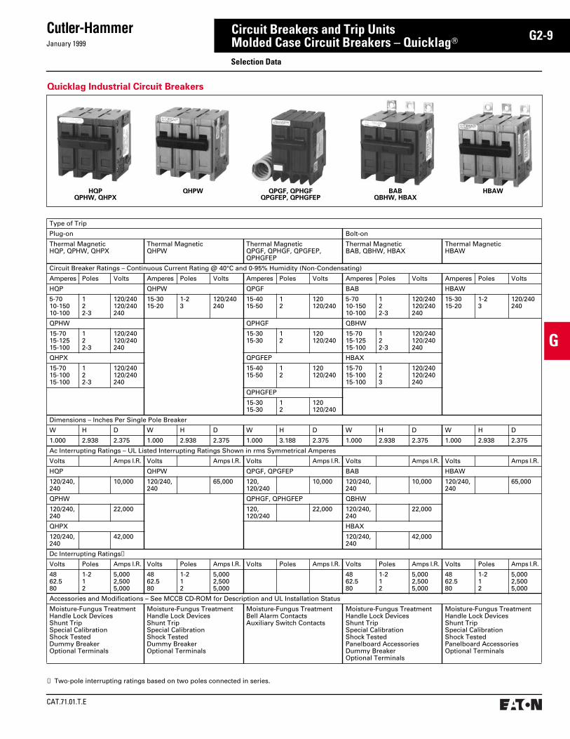
Circuit Breakers and Trip UnitsMolded Case Circuit Breakers – Quicklag
T
Selection Data
HQPQPHW, QHPX
QHPW QPGF, QPHGFQPGFEP, QPHGFEP
BABQBHW, HBAX
HBAW
Type of Trip
Plug-on Bolt-on
Thermal MagneticHQP, QPHW, QHPX
Thermal MagneticQHPW
Thermal MagneticQPGF, QPHGF, QPGFEP,QPHGFEP
Thermal MagneticBAB, QBHW, HBAX
Thermal MagneticHBAW
Circuit Breaker Ratings – Continuous Current Rating @ 40°C and 0-95% Humidity (Non-Condensating)
Amperes Poles Volts Amperes Poles Volts Amperes Poles Volts Amperes Poles Volts Amperes Poles Volts
HQP QHPW QPGF BAB HBAW
5-7010-15010-100
122-3
120/240120/240240
15-3015-20
1-23
120/240240
15-4015-50
12
120120/240
5-7010-15010-100
122-3
120/240120/240240
15-3015-20
1-23
120/240240
QPHW QPHGF QBHW
15-7015-12515-100
122-3
120/240120/240240
15-3015-30
12
120120/240
15-7015-12515-100
122-3
120/240120/240240
QHPX QPGFEP HBAX
15-7015-10015-100
122-3
120/240120/240240
15-4015-50
12
120120/240
15-7015-10015-100
123
120/240120/240240
QPHGFEP
15-3015-30
12
120120/240
Dimensions – Inches Per Single Pole Breaker
W H D W H D W H D W H D W H D
1.000 2.938 2.375 1.000 2.938 2.375 1.000 3.188 2.375 1.000 2.938 2.375 1.000 2.938 2.375
Ac Interrupting Ratings – UL Listed Interrupting Ratings Shown in rms Symmetrical Amperes
Volts Amps I.R. Volts Amps I.R. Volts Amps I.R. Volts Amps I.R. Volts Amps I.R.
HQP QHPW QPGF, QPGFEP BAB HBAW
120/240, 240
10,000 120/240, 240
65,000 120,120/240
10,000 120/240, 240
10,000 120/240, 240
65,000
QPHW QPHGF, QPHGFEP QBHW
120/240, 240
22,000 120,120/240
22,000 120/240, 240
22,000
QHPX HBAX
120/240, 240
42,000 120/240, 240
42,000
Dc Interrupting Ratings
➀
Volts Poles Amps I.R. Volts Poles Amps I.R. Volts Poles Amps I.R. Volts Poles Amps I.R. Volts Poles Amps I.R.
4862.580
1-212
5,0002,5005,000
4862.580
1-212
5,0002,5005,000
4862.580
1-212
5,0002,5005,000
4862.580
1-212
5,0002,5005,000
Accessories and Modifications – See MCCB CD-ROM for Description and UL Installation Status
Moisture-Fungus TreatmentHandle Lock DevicesShunt TripSpecial CalibrationShock TestedDummy BreakerOptional Terminals
Moisture-Fungus TreatmentHandle Lock DevicesShunt TripSpecial CalibrationShock TestedDummy BreakerOptional Terminals
Moisture-Fungus TreatmentBell Alarm ContactsAuxiliary Switch Contacts
Moisture-Fungus TreatmentHandle Lock DevicesShunt TripSpecial CalibrationShock TestedPanelboard AccessoriesDummy BreakerOptional Terminals
Moisture-Fungus TreatmentHandle Lock DevicesShunt TripSpecial CalibrationShock TestedPanelboard AccessoriesOptional Terminals
➀
Two-pole interrupting ratings based on two poles connected in series.
Quicklag Industrial Circuit Breakers

CAT.71.01.T.E
Cutler-Hammer
January 1999
G2-10
G
Circuit Breakers and Trip UnitsMolded Case Circuit Breakers – Quicklag
T
Selection Data
Type of Trip
Bolt-on Cable-in/Cable-out
Thermal MagneticQBGF, QBHGF, QBGFEP,QBHGFEP
Thermal MagneticQCR, QCF
Thermal MagneticQC, QCHW, QHCX
Thermal MagneticQHCW
Thermal MagneticQCGF, QCHGF, QCGFEP,QCHGFEP
Circuit Breaker Ratings – Continuous Current Rating @ 40°C and 0-95% Humidity (Non-Condensating)
Amperes Poles Volts Amperes Poles Volts Amperes Poles Volts Amperes Poles Volts Amperes Poles Volts
QBGF QCR, QCF QC QHCW QCGF
15-4015-50
12
120120/240
10-6010-6015-30
122-3
120120/240240
5-7010-12510-100
122-3
120/240120/240240
15-3015-20
1-23
120/240240
15-4015-50
12
120120/240
QBHGF QCHW QCHGF
15-3015-30
12
120120/240
15-7015-10015-100
122-3
120/240120/240240
15-3015-50
12
120120/240
QBGFEP QHCX QCGFEP
15-4015-50
12
120120/240
15-7015-10015-100
122-3
120/240120/240240
15-3015-50
12
120120/240
QBHGFEP QCHGFEP
15-3015-30
12
120120/240
15-5015-30
12
120120/240
Dimensions – Inches Per Single Pole Breaker
W H D W H D W H D W H D W H D
1.000 3.188 2.375 .500 3.938 2.625 1.000 3.750 2.438 1.000 3.750 2.438 1.000 3.750 2.438
Ac Interrupting Ratings – UL Listed Interrupting Ratings Shown in rms Symmetrical Amperes
Volts Amps I.R. Volts Amps I.R. Volts Amps I.R. Volts Amps I.R. Volts Amps I.R.
QBGF, QBGFEP QCR, QCF QC QHCW QCGF, QCGFEP
120,120/240
10,000 120/240 10,000 120/240,240
10,000 120/240, 240
65,000 120/240 10,000
QBHGF, QBHGFEP QCHW QCHGF, QCHGFEP
120,120/240
22,000 120/240,240
22,000 120 22,000
QHCX
120/240,240
42,000
Dc Interrupting Ratings
➀
Volts Poles Amps I.R. Volts Poles Amps I.R. Volts Poles Amps I.R. Volts Poles Amps I.R. Volts Poles Amps I.R.
62.5125
12
3,0003,000
4862.580
1-212
5,0002,5005,000
4862.580
1-212
5,0002,5005,000
Accessories and Modifications – See MCCB CD-ROM for Description and UL Installation Status
Moisture-Fungus TreatmentHandle Lock DevicesBell Alarm ContactsAuxiliary Switch ContactsRing Terminals
Moisture-Fungus TreatmentHandle Lock DevicesQCR Mounting ClipsRing TerminalsQuick ConnectTerminalsShunt TripShock Tested
Moisture-Fungus TreatmentHandle Lock DevicesShunt TripSpecial CalibrationShock TestedFace Mounting PlateBase Mounting HardwareOptional TerminalsDummy BreakerDIN Rail Mounting Clip
Moisture-Fungus TreatmentHandle Lock DevicesShunt TripSpecial CalibrationShock TestedFace Mounting PlateBase Mounting HardwareOptional TerminalsDummy BreakerDIN Rail Mounting Clip
Moisture-Fungus TreatmentHandle Lock DevicesBell Alarm ContactsAuxiliary Switch ContactsDIN Rail Mounting Clip
QBGF, QBHGF,QBGFEP, QBHGFEP
QCR, QCF QC, QCHW,QHCX
QHCW QCGF, QCHGF,QCGFEP, QCHGFEP
➀
Two-pole dc interrupting ratings based on two poles connected in series.
Quicklag Industrial Circuit Breakers

January 1999
Cutler-Hammer
CAT.71.01.T.E
G2-11
G
Circuit Breakers and Trip UnitsMolded Case Circuit Breakers – QuicklagT
Selection Data
Amperes
Factory Modifications➀
Type of Modification Breaker Types ModificationSuffix
Shunt Trip (Requires 1 extrapole space on right side) 120, 208, 240 Vac 12, 24, 48 Vac/Dc Draws 2.6 A at 120V Draws 11A at 24Vdc
QUICKLAG Types P, B and CQUICKLAG Types P, B and C
SS1
Special Calibration (50°C) QUICKLAG Types P, B and C V
Shock Testing QUICKLAG Types P, B and C L
Freeze Testing QUICKLAG Types P, B and C Y
Moisture-Fungus Treatment QUICKLAG Types P, B, Cand Ground Fault
F
240 Vac Rating➁ QUICKLAGT Types P, B, C2 and 3 pole only
H
Example – HQP
Breaker Type
1 070 V
Poles Modification Suffix1. 1 Pole
120/240 Vac
2. 2 Poles120/240 Vac240 Vac – use suffix H
3. 3 Poles240 Vac – use suffix H
Terminals
Breaker Type Cont.AmpereRating
Standard Line Terminal Standard Load Terminal Optional Terminals
TerminalType
WireType
WireRange
TerminalType
WireType
WireRange
Line Load
QUICKLAG Type P HQP, QPHW, QHPX, QHPW
10 to 3035 to 5015 to 3055 to 125
Plug-on female clips which matewith the bus stabs
A – 1- and 2-poleB B – 3-poleC
Cu/AlCu/AlCu/Al
#14-#4#14-#4#8-1/0
N/A CC. . . .
QUICKLAG Ground Fault QPGF, QPHGF, QPGFEP, QPHGFEP
10 to 30
40
Plug-on female clips which matewith the bus stabs
A – 1-poleD – 2-poleD
Cu/AlCu/AlCu
#14-#4#14-#8#14-#8
N/A CC. . . .
QUICKLAG Type B BAB, QBHW, HBAX, HBAW
10 to 3035 to 5015 to 3055 to 125
Extended tangs which boltdirectly to the bus
A – 1- and 2-poleB B – 3-poleC
Cu/AlCu/AlCu/Al
#14-#4#14-#4#8-1/0
N/A CC. . . .
QUICKLAG Ground Fault QBGF, QBHGF, QBGFEP, QBHGFEP
10 to 30
40
Extended tangs which boltdirectly to the bus
A – 1-poleD – 2-poleD
Cu/AlCu/AlCu
#14-#4#14-#8#14-#8
N/A N/A
QUICKLAG Type C QC, QCHW, QHCX, QHCW
10 to 2025 to 6070 to 125
EFG
Cu/AlCu/AlCu/Al
#14-#10#14-#10#14-#10
EBC
Cu/AlCu/AlCu/Al
#14-#10#14-#4#8-1/0
F, GE, GE
F, G, HE, F, G, HE, G, H
QUICKLAG QCR, QCF
10-5560
AA
Cu/AlCu
#14-#6#14-#6
AA
Cu/AlCu
#14-#4#14-#4
N/A N/A
QUICKLAG Ground Fault QCGF, QCHGF, QCGFEP, QCHGFEP
10 to 2025 to 50
EF
Cu/AlCu/Al
#14-#10#14-#10
AA
Cu/AlCu/Al
#14-#4#14-#4
F, GE, G
N/A
A B C D
E F G H
➀ Modifications do not apply to breaker types QCF and QCR at this time.
➁ 3-pole available in 240 Vac version only.
Quicklag Industrial Circuit Breaker Catalog Numbering System
Catalog Suffix “T”Suitable for Ring Lug Terminals
Catalog Suffix “P”Suitable for Quick Connect Terminals
SS1VLYFH

CAT.71.01.T.E
Cutler-HammerJanuary 1999
G2-12
G
Circuit Breakers and Trip UnitsMolded Case Circuit Breakers – Industrial G-FrameSelection Data
Types GHBS and GBHS Solenoid-Operated, Remote-Controlled
Dimensions Per Pole, Inches (mm)
Width Height Depth
1.000(25.40)
4.125(104.78)
2.810(71.37)
GHBS UL 489 Interrupting Ratings
Circuit BreakerType➀
Number of Poles
Interrupting Capacity (Symmetrical Amperes)
RatingAmperes➁
Volts Ac (50/60 Hz)
120 240 277/480
GHBS1015DGHBS1020DGHBS1030D
111
152030
65,00065,00065,000
–––
14,00014,00014,000
GHBS2015DGHBS2020DGHBS2030D
222
152030
–––
65,00065,00065,000
14,00014,00014,000
GBHS CSA 22.2 Interrupting Ratings
Circuit BreakerType
Number of Poles
Interrupting Capacity (Symmetrical Amperes)
RatingAmperes➁
Volts Ac (50/60 Hz)
347/600
GBHS1015DGBHS1020D
11
1520
10,00010,000
GBHS2015DGBHS2020D
22
1520
10,00010,000
Further InformationSee latest edition of MCCB CD-ROM,SA.74A.01.T.E and Cutler-Hammer Internet.
➀ All UL listed circuit breakers are HID (High Intensity Discharge) rated.
➁ Continuous current rating at 40°C.Dimensions in parentheses in millimeters.
DescriptionGHBS and GBHS circuit breakers are bolt-on branch circuit breakers designed for use in panelboards and are ideally suited for lighting control applications. In addition to providing conventional branch circuit protec-tion, they include a unique solenoid-operated mechanism that provides for efficient breaker pulse-on and pulse-off operation when used with a suitable controller like the Cutler-Ham-mer Pow-R-Command lighting control sys-tem.
Product Features● Bolt-on Line-Side Terminal● Cable Connected Load-Side
Terminal● 3-Prong Control Terminal (Common, Sole-
noid, Auxiliary Switch)● Bi-Metal Assembly for Thermal
Overload Protection● Fast Acting Short Circuit Protection● Arc-Runner and Arc-Chute Assembly for
Fast Acting Arc Extinction● Three Position Handle: OFF, TRIP
(Center), ON● Handle in “ON” Position Enables
Remote Control● Handle in “OFF” Position Disables
Remote Control● Handle Permits Manual Switching When
Control Power is Lost● Mechanical Trip Indicator Window
(Red-ON, Green-OFF/TRIPPED)● 15 and 20 Ampere Breakers SWD (Switch-
ing Duty) Rated● HID Ratings for HID (High Intensity
Discharge) Lighting● Auxiliary Switch for Control Circuit Feed-
back
1-Pole 2-Pole
Terminal TypeFor load-side. Terminals are UL listed as suitable for wire type and size given below.
Circuit Breaker Amperes Terminal Type Screw Head Type Wire Type AWG Wire Range
15-20 Clamp Slotted Cu/Al #14-#10
30 Box Slotted Cu/Al #14-#2
15-20 Amperes 30 Amperes
Note: For use in lighting control applications, see Pow-R-Command section F2.

January 1999
Cutler-Hammer
CAT.71.01.T.E
G2-13
G
Circuit Breakers and Trip UnitsMolded Case Circuit Breakers – Industrial G-FrameSelection Data
Typical Single-Pole Circuit Breaker Schematic Diagram and Conductor Plug Wiring Connections
Typical 2-Pole Circuit Breaker Schematic Diagram and Conductor Plug Wiring Connections
2-Pole Circuit Breaker
SolenoidCommon
28 Vac
Auxiliary
Solenoida
Solenoida
1/2 CycleMaximum28 VacPulse Source
AMP Inc.ConductorPlug
Solenoid
AuxiliarySwitch
Common
ConductorPlug (AsViewed FromEnd)
Circuit BreakerOpen/ClosedStatus
1-Pole Circuit Breaker
Solenoid
Solenoid
a
Common
28 Vac
AMP Inc.ConductorPlug
1/2 CycleMaximum28 VacPulse Source
Circuit BreakerOpen/ClosedStatus
Auxiliary
Solenoid
AuxiliarySwitch
Common
ConductorPlug (AsViewed FromEnd)
Types GHBS and GBHS Solenoid-Operated, Remote-Controlled
Remote Control OperationThe remote-control capability of the breaker is “armed” when the breaker handle is man-ually switched to the “ON” position. Once armed, the breaker can be pulsed “ON” and “OFF” by a controller device which provides an ac pulse of specified magnitude and dura-tion to the solenoid operated mechanism. Control connections to the breaker are pro-vided through a male conductor plug (sup-
plied by others) which snaps into the female connector provided with the breaker. A nor-mally open (a) auxiliary contact provides for breaker “ON”/“OFF” status indication to the remote controller and/or indicating lamp.
The remote-control capability of the breaker is “disarmed” when the breaker handle is in the “OFF” or “TRIPPED” position. In the event the breaker automatically trips, the breaker must be reset manually.
Breaker Solenoid and Operating Data● Ambient Temperature:
0-40 Degrees C● Nominal Pulse Magnitude:
28 volts ac RMS● Tolerance: +10% to -15% of
Nominal Voltage● Pulse Duration: 1/2 cycle (8-10 ms)● Minimum Recommended Pulse
Current at Nominal Voltage:1-Pole: 4.9 Amperes Peak, 3.5 Amperes RMS2-Pole: 7.84 Amperes Peak,5.6 Amperes RMS
● Breaker Operating Time: 20-40 ms● Maximum Breaker Cycling:
6 Operations per Minute● Humidity: 0-95% non-Condensing
CAT.71.01.T.E
Cutler-Hammer
January 1999
G2-14
G
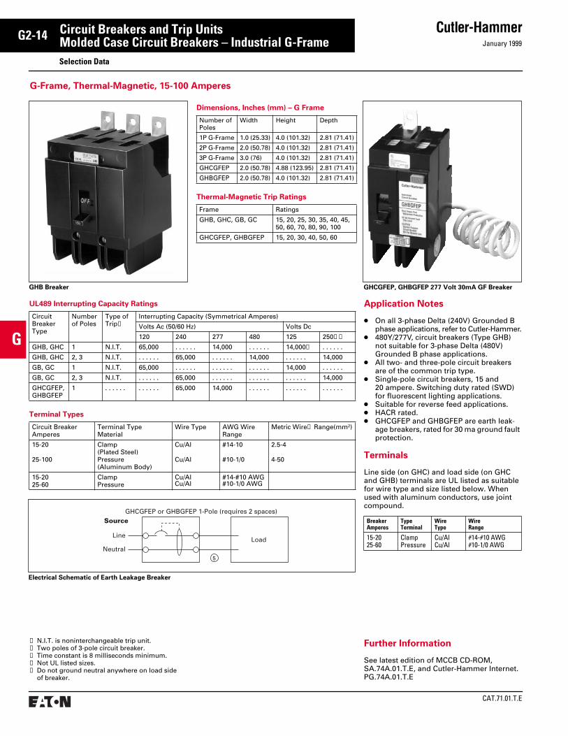
Circuit Breakers and Trip UnitsMolded Case Circuit Breakers – Industrial G-Frame
Selection Data
➀
N.I.T. is noninterchangeable trip unit.
➁
Two poles of 3-pole circuit breaker.
➂
Time constant is 8 milliseconds minimum.
➃
Not UL listed sizes.
➄
Do not ground neutral anywhere on load side of breaker.
UL489 Interrupting Capacity Ratings
Circuit Breaker Type
Number of Poles
Type of Trip
➀
Interrupting Capacity (Symmetrical Amperes)
Volts Ac (50/60 Hz) Volts Dc
120 240 277 480 125 250
➁➂
GHB, GHC 1 N.I.T. 65,000 . . . . . . 14,000 . . . . . . 14,000
➂
. . . . . .
GHB, GHC 2, 3 N.I.T. . . . . . . 65,000 . . . . . . 14,000 . . . . . . 14,000
GB, GC 1 N.I.T. 65,000 . . . . . . . . . . . . . . . . . . 14,000 . . . . . .
GB, GC 2, 3 N.I.T. . . . . . . 65,000 . . . . . . . . . . . . . . . . . . 14,000
GHCGFEP, GHBGFEP
1 . . . . . . . . . . . . 65,000 14,000 . . . . . . . . . . . . . . . . . .
Terminal Types
Circuit BreakerAmperes
Terminal Type Material
Wire Type AWG WireRange
Metric Wire
➃
Range(mm
2
)
15-20
25-100
Clamp(Plated Steel)Pressure(Aluminum Body)
Cu/Al
Cu/Al
#14-10
#10-1/0
2.5-4
4-50
15-2025-60
Clamp Pressure
Cu/AlCu/Al
#14-#10 AWG#10-1/0 AWG
Dimensions, Inches (mm) – G Frame
Number of Poles
Width Height Depth
1P G-Frame 1.0 (25.33) 4.0 (101.32) 2.81 (71.41)
2P G-Frame 2.0 (50.78) 4.0 (101.32) 2.81 (71.41)
3P G-Frame 3.0 (76) 4.0 (101.32) 2.81 (71.41)
GHCGFEP 2.0 (50.78) 4.88 (123.95) 2.81 (71.41)
GHBGFEP 2.0 (50.78) 4.0 (101.32) 2.81 (71.41)
Thermal-Magnetic Trip Ratings
Frame Ratings
GHB, GHC, GB, GC 15, 20, 25, 30, 35, 40, 45, 50, 60, 70, 80, 90, 100
GHCGFEP, GHBGFEP 15, 20, 30, 40, 50, 60
Application Notes
●
On all 3-phase Delta (240V) Grounded B phase applications, refer to Cutler-Hammer.
●
480Y/277V, circuit breakers (Type GHB) not suitable for 3-phase Delta (480V) Grounded B phase applications.
●
All two- and three-pole circuit breakers are of the common trip type.
●
Single-pole circuit breakers, 15 and 20 ampere. Switching duty rated (SWD) for fluorescent lighting applications.
●
Suitable for reverse feed applications.
●
HACR rated.
●
GHCGFEP and GHBGFEP are earth leak-age breakers, rated for 30 ma ground fault protection.
Terminals
Line side (on GHC) and load side (on GHC and GHB) terminals are UL listed as suitable for wire type and size listed below. When used with aluminum conductors, use joint compound.
BreakerAmperes
TypeTerminal
WireType
WireRange
15-2025-60
ClampPressure
Cu/AlCu/Al
#14-#10 AWG#10-1/0 AWG
Further Information
See latest edition of MCCB CD-ROM, SA.74A.01.T.E, and Cutler-Hammer Internet.PG.74A.01.T.E
G-Frame, Thermal-Magnetic, 15-100 Amperes
Source
Line
Neutral
GHCGFEP or GHBGFEP 1-Pole (requires 2 spaces)
Load
5
Electrical Schematic of Earth Leakage Breaker
GHB Breaker GHCGFEP, GHBGFEP 277 Volt 30mA GF Breaker

January 1999
Cutler-Hammer
CAT.71.01.T.E
G2-15
G
Circuit Breakers and Trip UnitsMolded Case Circuit Breakers – Series CT
Selection Data
Series C Circuit Breaker/Frame Catalog Numbering System
Circuit Breaker Frame Type
Number of Poles
Circuit Breaker Frame Ampere Rating
Digitrip Trip Unit Type Suffix
GDEDEDHEDCEHDFDBFDHFDFDCJDBJDHJDJDCDKKDBKDCKDHKDCHDKKDCLDBLDCLDHLDCHLDLDCCLDCMDLBMDLCMDLHMDLBHMDLCHMDLNDCNDHNDCHNDNDCCNDCRDCRDRDCCRDC
1234
1520303540455060708090
100 (Max. G-Frame)110125150 (Max. EHD-Frame)175200225 (Max. E&F-Frame)250 (Max. J-Frame)300350400 (Max. K-Frame)450500600 (Max. L-Frame)700800 (Max. M-Frame)900
10001200 (Max. N-Frame)125014001500160020002500 (Max. R-Frame)
T32 (Digitrip 310 LSI)T33 (Digitrip 310 LS)T35 (Digitrip 310 LSG)T36 (Digitrip 310 LSIG)T55 (OPTIM 550 LSI)T56 (OPTIM 550 LSIG)T57 (OPTIM 550 LSIA)T76 (OPTIM 1050 LSIG)T77 (OPTIM 750 LSIA)
T106 (OPTIM 1050 LSIG)T107 (OPTIM 1050 LSIA)
C – CU TerminalsE – Protected Neutral PoleF – Frame OnlyK – Molded Case SwitchT – Trip Unit OnlyV – 50°C CalibrationW – Without TerminalsX – Load Side Terminals OnlyY – Line Side Terminals Only
Example:
KD 3 400 T57 W
Note: This chart is for interpretation of Cutler-Hammer catalog numbers and not for the creation of catalog numbers.
CAT.71.01.T.E
Cutler-Hammer
January 1999
G2-16
G
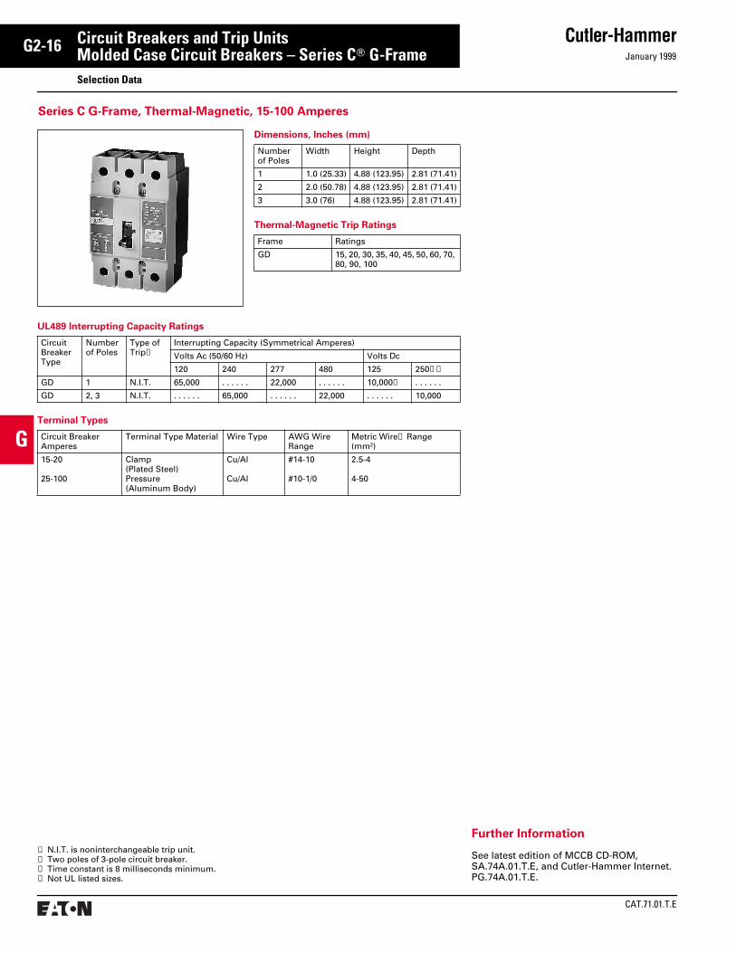
Circuit Breakers and Trip UnitsMolded Case Circuit Breakers – Series C
T
G-Frame
Selection Data
➀
N.I.T. is noninterchangeable trip unit.
➁
Two poles of 3-pole circuit breaker.
➂
Time constant is 8 milliseconds minimum.
➃
Not UL listed sizes.
UL489 Interrupting Capacity Ratings
Circuit Breaker Type
Number of Poles
Type of Trip
➀
Interrupting Capacity (Symmetrical Amperes)
Volts Ac (50/60 Hz) Volts Dc
120 240 277 480 125 250
➁➂
GD 1 N.I.T. 65,000 . . . . . . 22,000 . . . . . . 10,000
➂
. . . . . .
GD 2, 3 N.I.T. . . . . . . 65,000 . . . . . . 22,000 . . . . . . 10,000
Terminal Types
Circuit BreakerAmperes
Terminal Type Material Wire Type AWG WireRange
Metric Wire
➃
Range(mm
2
)
15-20
25-100
Clamp(Plated Steel)Pressure(Aluminum Body)
Cu/Al
Cu/Al
#14-10
#10-1/0
2.5-4
4-50
Dimensions, Inches (mm)
Number of Poles
Width Height Depth
1 1.0 (25.33) 4.88 (123.95) 2.81 (71.41)
2 2.0 (50.78) 4.88 (123.95) 2.81 (71.41)
3 3.0 (76) 4.88 (123.95) 2.81 (71.41)
Thermal-Magnetic Trip Ratings
Frame Ratings
GD 15, 20, 30, 35, 40, 45, 50, 60, 70, 80, 90, 100
Further Information
See latest edition of MCCB CD-ROM, SA.74A.01.T.E, and Cutler-Hammer Internet.PG.74A.01.T.E.
Series C G-Frame, Thermal-Magnetic, 15-100 Amperes

January 1999
Cutler-Hammer
CAT.71.01.T.E
G2-17
G
Circuit Breakers and Trip UnitsMolded Case Circuit Breakers – Series C
T
F-Frame
Selection Data
➀
N.I.T. is noninterchangeable trip unit.
➁
2-pole circuit breaker, or two poles of 3-pole circuit breaker.
➂
Time constant is 3 milliseconds minimum at 10 kA and 8 milliseconds minimum at 22 kA.
➃
Current limiting.
➄
HFDDC is UL only and is not tested to other standards.
UL489 Interrupting Capacity Ratings
Circuit BreakerType
NumberofPoles
TypeofTrip
➀
Interrupting Capacity (Symmetrical Amperes)
Volts Ac (50/60 Hz) Volts Dc
240 277 480 600 125 250
➁➂
EDEDHEDC
➃
2, 32, 32, 3
N.I.T. 65,000100,000200,000
. . . . . .
. . . . . .
. . . . . .
. . . . . .
. . . . . .
. . . . . .
. . . . . .
. . . . . .
. . . . . .
10,00010,00010,000
. . . . . . . . . . . . . . . . . .
EHD 12, 3
N.I.T. . . . . . . 18,000
14,000. . . . . .
. . . . . . 14,000
. . . . . .
. . . . . .10,000. . . . . .
. . . . . .10,000
FDB 2, 3, 4 N.I.T. 18,000 . . . . . . 14,000 14,000 . . . . . . 10,000
FD 12, 3, 4
N.I.T. . . . . . . 65,000
25,000. . . . . .
. . . . . . 25,000
. . . . . .18,000
10,000. . . . . .
. . . . . .10,000
HFD 12, 3, 4
N.I.T. . . . . . .100,000
65,000. . . . . .
. . . . . . 65,000
. . . . . .25,000
10,000. . . . . .
. . . . . .22,000
FDC
➃
2, 3, 4 N.I.T. 200,000 . . . . . . 100,000 35,000 . . . . . . 22,000
HFDDC
➄
3 N.I.T. . . . . . . . . . . . . . . . . . . . . . . . . . . . . . . 42,000
➅
Dimensions, Inches (mm)
Number of Poles
Width Height Depth
1 1.375 (35) 6 (152) 3.375 (86)
2 2.75 (70) 6 (152) 3.375 (86)
3 4.125 (105) 6 (152) 3.375 (86)
4 5.5 (140) 6 (152) 3.375 (86)
Thermal-Magnetic Trip Ratings
Frame Ratings
ED, EDH, EDC 100, 125, 150, 175, 200, 225
EHD, FDB, FD,HFD, FDC, HFDDC
10, 15, 20, 25, 30, 35, 40, 45, 50, 60, 70, 80, 90, 100, 110, 125, 150
FD, HFD, FDC 175, 200, 225
Line and Load Terminals
MaximumBreakerAmperes
TerminalBody Material
Wire Type AWG Wire Range
Metric Wire Range mm
2
Catalog Numbers
Package of 3 Terminals
Standard Pressure Type Terminals
20 (EHD)100150225
SteelSteelAluminumAluminum
Cu/AlCu/AlCu/AlCu/Al
#14-#10#14-1/0#4-4/0#4-4/0
2.5-42.5-5025-9525-95
3T20FB
➆
3T100FB3TA150FB3TA225FD
Optional Pressure Terminals
50100150225
AluminumAluminumStainless SteelAluminum
Cu/AlCu/AlCuCu/Al
#14-#4#14-1/0#4-4/0#6-300 kcmil
2.5-162.5-5025-9516-150
3TA50FB
➆
3TA100FD3T150FB3TA225FDK
Further Information
See latest edition of MCCB CD-ROM, SA.74A.01.T.E, and Cutler-Hammer Internet.PG.74A.01.T.E.
➅
Interrupting rating is 35,000 amperes at 600 Vdc with 3 poles in series, for ungrounded systems only.
➆
Not for use with ED, EDH, EDC breakers.
Series C F-Frame, Thermal-Magnetic, 100-225 Amperes
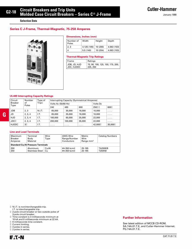
CAT.71.01.T.E
Cutler-HammerJanuary 1999
G2-18
G
Circuit Breakers and Trip UnitsMolded Case Circuit Breakers – Series CT J-FrameSelection Data
UL489 Interrupting Capacity Ratings
CircuitBreakerType
NumberofPoles
Type of Trip➀
Interrupting Capacity (Symmetrical Amperes)
Volts Ac (50/60 Hz) Volts Dc
240 480 600 250➁➂ 600➃
JDB 2, 3 N.I.T. 65,000 35,000 18,000 10,000 . . . .
JD 2, 3, 4 I.T. 65,000 35,000 18,000 10,000 . . . .
HJD 2, 3, 4 I.T. 100,000 65,000 25,000 22,000 . . . .
JDC➄ 2, 3, 4 I.T. 200,000 100,000 35,000 22,000 . . . .
HJDDC 3➅ I.T. . . . . . . . . . . . . 42,000➆ 35,000➅
➀ N.I.T. is noninterchangeable trip.I.T. is interchangeable trip.
➁ 2-pole circuit breaker or two outside poles of 3-pole circuit breaker.
➂ Time constant is 3 milliseconds minimum at 10 kA and 8 milliseconds minimum at 22 kA.
➃ 8 milliseconds time constant.➄ Current limiting.➅ 3 poles in series.➆ 2 poles in series.
Line and Load Terminals
MaximumBreakerAmperes
TerminalBodyMaterial
WireType
AWG WireRange/Number Conductors
MetricWireRange mm2
Catalog Numbers
Standard Cu/Al Pressure Terminals
250250
AluminumStainless Steel
Cu/AlCu
#4-350 kcmil#4-350 kcmil
25-18525-185
TA250KBT250KB
Further Information
See latest edition of MCCB CD-ROM, SA.74A.01.T.E, and Cutler-Hammer Internet.PG.74A.01.T.E.
Series C J-Frame, Thermal-Magnetic, 75-250 Amperes
Dimensions, Inches (mm)
Number of Poles
Width Height Depth
2, 3 4.125 (105) 10 (255) 4.063 (103)
4 5.5 (140) 10 (254) 4.063 (103)
Thermal-Magnetic Trip Ratings
Frame Ratings
JDB, JD, HJDJDC, HJDDC
70, 90, 100, 125, 150, 175, 200,225, 250
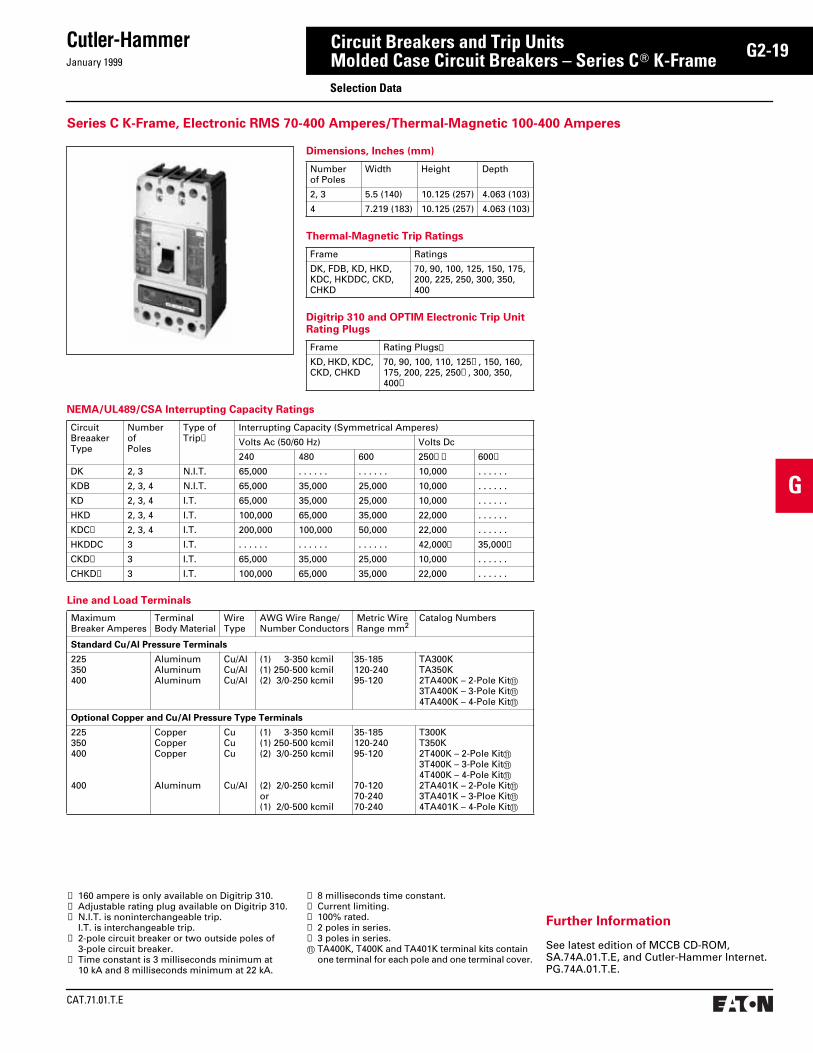
January 1999
Cutler-Hammer
CAT.71.01.T.E
G2-19
G
Circuit Breakers and Trip UnitsMolded Case Circuit Breakers – Series CT K-Frame
Series C K-Frame, Electronic RMS 70-400 Amperes/Thermal-Magnetic 100-400 Amperes
Selection Data
NEMA/UL489/CSA Interrupting Capacity Ratings
CircuitBreaakerType
NumberofPoles
Type of Trip➂
Interrupting Capacity (Symmetrical Amperes)
Volts Ac (50/60 Hz) Volts Dc
240 480 600 250➃➄ 600➅
DK 2, 3 N.I.T. 65,000 . . . . . . . . . . . . 10,000 . . . . . .
KDB 2, 3, 4 N.I.T. 65,000 35,000 25,000 10,000 . . . . . .
KD 2, 3, 4 I.T. 65,000 35,000 25,000 10,000 . . . . . .
HKD 2, 3, 4 I.T. 100,000 65,000 35,000 22,000 . . . . . .
KDC➆ 2, 3, 4 I.T. 200,000 100,000 50,000 22,000 . . . . . .
HKDDC 3 I.T. . . . . . . . . . . . . . . . . . . 42,000➈ 35,000➉
CKD➇ 3 I.T. 65,000 35,000 25,000 10,000 . . . . . .
CHKD➇ 3 I.T. 100,000 65,000 35,000 22,000 . . . . . .
➀ 160 ampere is only available on Digitrip 310.➁ Adjustable rating plug available on Digitrip 310.➂ N.I.T. is noninterchangeable trip.
I.T. is interchangeable trip.➃ 2-pole circuit breaker or two outside poles of
3-pole circuit breaker.➄ Time constant is 3 milliseconds minimum at
10 kA and 8 milliseconds minimum at 22 kA.
Line and Load Terminals
Maximum Breaker Amperes
Terminal Body Material
Wire Type
AWG Wire Range/Number Conductors
Metric Wire Range mm2
Catalog Numbers
Standard Cu/Al Pressure Terminals
225350400
AluminumAluminumAluminum
Cu/AlCu/AlCu/Al
(1) 3-350 kcmil(1) 250-500 kcmil(2) 3/0-250 kcmil
35-185120-24095-120
TA300KTA350K2TA400K – 2-Pole Kitk3TA400K – 3-Pole Kitk4TA400K – 4-Pole Kitk
Optional Copper and Cu/Al Pressure Type Terminals
225350400
400
CopperCopperCopper
Aluminum
CuCuCu
Cu/Al
(1) 3-350 kcmil(1) 250-500 kcmil(2) 3/0-250 kcmil
(2) 2/0-250 kcmilor(1) 2/0-500 kcmil
35-185120-24095-120
70-12070-24070-240
T300KT350K2T400K – 2-Pole Kitk3T400K – 3-Pole Kitk4T400K – 4-Pole Kitk2TA401K – 2-Pole Kitk3TA401K – 3-Ploe Kitk4TA401K – 4-Pole Kitk
➅ 8 milliseconds time constant.➆ Current limiting.➇ 100% rated.➈ 2 poles in series.➉ 3 poles in series.k TA400K, T400K and TA401K terminal kits contain
one terminal for each pole and one terminal cover.
Further Information
See latest edition of MCCB CD-ROM, SA.74A.01.T.E, and Cutler-Hammer Internet.PG.74A.01.T.E.
Dimensions, Inches (mm)
Number of Poles
Width Height Depth
2, 3 5.5 (140) 10.125 (257) 4.063 (103)
4 7.219 (183) 10.125 (257) 4.063 (103)
Thermal-Magnetic Trip Ratings
Frame Ratings
DK, FDB, KD, HKD, KDC, HKDDC, CKD, CHKD
70, 90, 100, 125, 150, 175, 200, 225, 250, 300, 350, 400
Digitrip 310 and OPTIM Electronic Trip Unit Rating Plugs
Frame Rating Plugs➀
KD, HKD, KDC, CKD, CHKD
70, 90, 100, 110, 125➁, 150, 160, 175, 200, 225, 250➁, 300, 350, 400➁
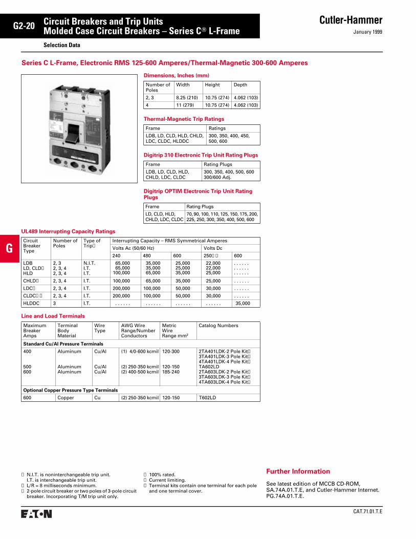
CAT.71.01.T.E
Cutler-HammerJanuary 1999
G2-20
G
Circuit Breakers and Trip UnitsMolded Case Circuit Breakers – Series CT L-FrameSelection Data
➀ N.I.T. is noninterchangeable trip unit.I.T. is interchangeable trip unit.
➁ L/R = 8 milliseconds minimum.➂ 2-pole circuit breaker or two poles of 3-pole circuit
breaker. Incorporating T/M trip unit only.
➃ 100% rated.➄ Current limiting.➅ Terminal kits contain one terminal for each pole
and one terminal cover.
Line and Load Terminals
Maximum Breaker Amps
TerminalBodyMaterial
WireType
AWG WireRange/NumberConductors
MetricWireRange mm2
Catalog Numbers
Standard Cu/Al Pressure Terminals
400
500600
Aluminum
AluminumAluminum
Cu/Al
Cu/AlCu/Al
(1) 4/0-600 kcmil
(2) 250-350 kcmil(2) 400-500 kcmil
120-300
120-150185-240
2TA401LDK-2 Pole Kit➅3TA401LDK-3 Pole Kit➅4TA401LDK-4 Pole Kit➅TA602LD2TA603LDK-2 Pole Kit➅3TA603LDK-3 Pole Kit➅4TA603LDK-4 Pole Kit➅
Optional Copper Pressure Type Terminals
600 Copper Cu (2) 250-350 kcmil 120-150 T602LD
UL489 Interrupting Capacity Ratings
Circuit Breaker Type
Number ofPoles
Type of Trip➀
Interrupting Capacity – RMS Symmetrical Amperes
Volts Ac (50/60 Hz) Volts Dc
240 480 600 250➁➂ 600
LDBLD, CLD➃HLD
2, 32, 3, 42, 3, 4
N.I.T.I.T.I.T.
65,00065,000
100,000
35,000 35,000 65,000
25,000 25,000 35,000
22,000 22,000 25,000
. . . . . .
. . . . . .
. . . . . .
CHLD➃ 2, 3, 4 I.T. 100,000 65,000 35,000 25,000 . . . . . .
LDC➄ 2, 3, 4 I.T. 200,000 100,000 50,000 30,000 . . . . . .
CLDC➃➄ 2, 3, 4 I.T. 200,000 100,000 50,000 30,000 . . . . . .
HLDDC 3 I.T. . . . . . . . . . . . . . . . . . . . . . . . . 35,000
Dimensions, Inches (mm)
Number of Poles
Width Height Depth
2, 3 8.25 (210) 10.75 (274) 4.062 (103)
4 11 (279) 10.75 (274) 4.062 (103)
Thermal-Magnetic Trip Ratings
Frame Ratings
LDB, LD, CLD, HLD, CHLD, LDC, CLDC, HLDDC
300, 350, 400, 450, 500, 600
Digitrip 310 Electronic Trip Unit Rating Plugs
Frame Rating Plugs
LDB, LD, CLD, HLD, CHLD, LDC, CLDC
300, 350, 400, 500, 600 300/600 Adj.
Digitrip OPTIM Electronic Trip Unit Rating Plugs
Frame Rating Plugs
LD, CLD, HLD, CHLD, LDC, CLDC
70, 90, 100, 110, 125, 150, 175, 200, 225, 250, 300, 350, 400, 500, 600
Series C L-Frame, Electronic RMS 125-600 Amperes/Thermal-Magnetic 300-600 Amperes
Further Information
See latest edition of MCCB CD-ROM, SA.74A.01.T.E, and Cutler-Hammer Internet.PG.74A.01.T.E.

January 1999
Cutler-Hammer
CAT.71.01.T.E
G2-21
G
Circuit Breakers and Trip UnitsMolded Case Circuit Breakers – Series CT M-FrameSelection Data
Line and Load Terminals
UL489 Interrupting Capacity Ratings
Circuit Breaker Type
Number of Poles
Type of Trip➀
Interrupting Capacity – RMSSymmetrical Amperes
Volts Ac (50/60 Hz) Volts Dc➁➂
240 480 600 250
MDL, CMDL➃HMDL, CHMDL➃
2, 32, 3
N.I.T.N.I.T.
65,000100,000
50,00065,000
25,00035,000
22,00025,000
Maximum Breaker Amperes
Terminal BodyMaterial
Wire Type AWG Wire Range/Number of Conductors
Catalog Numbers
Standard Cu/Al Pressure Terminals
600800800
AluminumAluminumAluminum
Cu/AlCu/AlCu/Al
(2) #1-500 kcmil(3) 3/0-400 kcmil(2) 500-750 kcmil
TA700MA1TA800MA2TA801MA
Optional Copper and Cu/Al Pressure Type Terminals
600800
CopperCopper
CuCu
(2) 2/0-500 kcmil(3) 3/0-300 kcmil
T600MA1T800MA1
➀ N.I.T. is noninterchangeable trip unit.➁ Two poles or two poles of 3-pole circuit breaker.
Thermal-magnetic trip units only, MDL, HMDL breakers with electronic trip unit are not Dc rated.
➂ Time constant is 3 milliseconds minimum at 10 kA and 8 milliseconds minimum at 22 kA.
➃ 100% rated. Not for use on Dc.
Dimensions, Inches (mm)
Width Height Depth
8.25 (210) 16 (406) 4.062 (103)
Thermal-Magnetic Trip Ratings
Frame Ratings
MDL 300, 400, 450, 500, 600, 700, 800
Digitrip 310 Electronic Trip Unit Rating Plugs
Frame Rating Plugs
MDL 400, 500, 600, 700, 800, 400/800 Adj.
Series C M-Frame, Electronic RMS 400-800 Amperes/Thermal-Magnetic 300-800 Amperes
Further Information
See latest edition of MCCB CD-ROM, SA.74A.01.T.E, and Cutler-Hammer Internet.PG.74A.01.T.E.
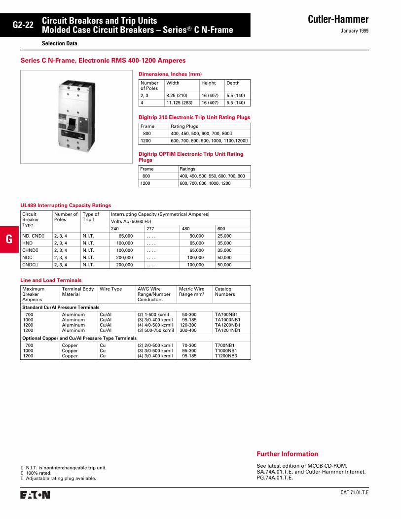
CAT.71.01.T.E
Cutler-HammerJanuary 1999
G2-22
G
Circuit Breakers and Trip UnitsMolded Case Circuit Breakers – SeriesT C N-FrameSelection Data
Line and Load Terminals
UL489 Interrupting Capacity Ratings
Circuit Breaker Type
Number of Poles
Type of Trip➀
Interrupting Capacity (Symmetrical Amperes)
Volts Ac (50/60 Hz)
240 277 480 600
ND, CND➁ 2, 3, 4 N.I.T. 65,000 . . . . 50,000 25,000
HND 2, 3, 4 N.I.T. 100,000 . . . . 65,000 35,000
CHND➁ 2, 3, 4 N.I.T. 100,000 . . . . 65,000 35,000
NDC 2, 3, 4 N.I.T. 200,000 . . . . 100,000 50,000
CNDC➁ 2, 3, 4 N.I.T. 200,000 . . . . 100,000 50,000
Maximum BreakerAmperes
Terminal Body Material
Wire Type AWG Wire Range/Number Conductors
Metric Wire Range mm2
CatalogNumbers
Standard Cu/Al Pressure Terminals
700100012001200
AluminumAluminumAluminumAluminum
Cu/AlCu/AlCu/AlCu/Al
(2) 1-500 kcmil(3) 3/0-400 kcmil(4) 4/0-500 kcmil(3) 500-750 kcmil
50-30095-185
120-300300-400
TA700NB1TA1000NB1TA1200NB1TA1201NB1
Optional Copper and Cu/Al Pressure Type Terminals
70010001200
CopperCopperCopper
CuCuCu
(2) 2/0-500 kcmil(3) 3/0-500 kcmil(4) 3/0-400 kcmil
70-30095-30095-185
T700NB1T1000NB1T1200NB3
➀ N.I.T. is noninterchangeable trip unit.➁ 100% rated.➂ Adjustable rating plug available.
Dimensions, Inches (mm)
Numberof Poles
Width Height Depth
2, 3 8.25 (210) 16 (407) 5.5 (140)
4 11.125 (283) 16 (407) 5.5 (140)
Digitrip 310 Electronic Trip Unit Rating Plugs
Frame Rating Plugs
800 400, 450, 500, 600, 700, 800➂
1200 600, 700, 800, 900, 1000, 1100,1200➂
Digitrip OPTIM Electronic Trip Unit Rating Plugs
Frame Ratings
800 400, 450, 500, 550, 600, 700, 800
1200 600, 700, 800, 1000, 1200
Series C N-Frame, Electronic RMS 400-1200 Amperes
Further Information
See latest edition of MCCB CD-ROM, SA.74A.01.T.E, and Cutler-Hammer Internet.PG.74A.01.T.E.

January 1999
Cutler-Hammer
CAT.71.01.T.E
G2-23
G
Circuit Breakers and Trip UnitsMolded Case Circuit Breakers – Series CT R-FrameSelection Data
Dimensions, Inches (mm)
Number of Poles
Width Height Depth
3 15.5 (394) 16 (406) 9.75 (248)
4 20 (508) 16 (406) 9.75 (248)
Digitrip 310 Electronic Trip Unit Rating Plugs
Frame Rating Plugs
1600 800, 1000, 1200, 1250, 1400, 1500, 1600➀
2000 1000, 1200, 1250, 1400, 1600, 2000➀
2500 1200, 1250, 1600, 2000, 2500➀
Digitrip RMS and Digitrip OPTIM Electronic Trip Unit Rating Plugs
Frame Rating Plugs
1600 800, 1000, 1200, 1600
2000 1000, 1200, 1600, 2000
2500 1600, 2000, 2500
UL489 Interrupting Capacity Ratings
Circuit Breaker Frame
Number of Poles
Type of Trip➁
Interrupting Capacity (Symmetrical Amperes)
Volts Ac (50/60 Hz)
240 277 480 600
RD 3, 4 N.I.T. 125 . . . . 65 50
CRD➂ 3, 4 N.I.T. 125 . . . . 65 50
RDC 3, 4 N.I.T. 200 . . . . 100 65
CRDC➂ 3, 4 N.I.T. 200 . . . . 100 65
Line and Load Terminals
Catalog Numbers
Maximum Breaker Amperes
Terminal Body Material
Wire Type Hardware AWG/MCMWire Range/NumberConductors
Metric Wire Range mm2
Wire Terminal
TA1600RDT1600RDTA2000RD
160016002000
AluminumCopperAluminum
Cu/AlCuCu/Al
EnglishEnglishEnglish
(4) 500-1000 kcmil(4) 1-600 kcmil(6) 2-600 kcmil
300-50050-30035-300
➀ Adjustable rating plug available.➁ N.I.T. is noninterchangeable trip unit.➂ 100% rated versions.
Series C R-Frame, Electronic RMS 800-2500 Amperes
Further Information
See latest edition of MCCB CD-ROM, SA.74A.01.T.E, and Cutler-Hammer Internet.PG.74A.01.T.E.

CAT.71.01.T.E
Cutler-HammerJanuary 1999
G2-24
G
Circuit Breakers and Trip UnitsMolded Case Circuit Breakers – Current LimitingSelection Data
Dimensions, Inches (mm)
Frame Number of Poles
Width Height Depth
FCL 2, 3 4.125 (104.73)
8.75 (222.16)
3.5(88.7)
LCL 2, 3 8.25 (209.47)
16 (406.29)
4 (101.56)
Thermal-Magnetic Trip Ratings
Frame Ratings
FCL 15, 20, 25, 30, 35, 40, 45, 50,60, 70, 80, 90, 100
SELTRONIC Electronic Trip Unit Rating Plug
Frame Ratings
LCL 125, 150, 175, 200, 225, 250,275, 300, 350, 400
Interrupting Capacity Ratings
On all 3-phase Delta, Ground B phase applica-tions, refer to Cutler-Hammer.
Terminals
Breakers listed include line and load termi-nals. Terminals are Underwriters Laborato-ries, Inc. listed for wire sizes and types listed below. When used with aluminum cable, use joint compound. To order optional aluminum terminals, add suffix “Z” to breaker catalog number listed.
Volts Ac (50/60 Hz)
Type of Trip➀
Interrupting Capacity (Symmetrical Amperes)
240480
N.I.T.N.I.T.
200,000150,000
Maximum BreakerAmperes
Wire Type AWG Wire Range
Standard Pressure Terminals
100 Al/Cu #14-1/0
Optional Al/Cu Pressure Terminals
50100
Al/CuAl/Cu
#14-#4#4-4/0
➀ N.I.T. is noninterchangeable trip unit.
FCL Frame
Listed with Underwriters Laboratories, Inc. except as noted.Type LCL breakers are not defined in Federal Specifications W-C-375-b.
Interrupting Capacity Ratings
On all 3-phase Delta, Ground B phase applica-tions, refer to Cutler-Hammer.
Terminals
Two terminals are required per pole. Terminals are Underwriters Laboratories, Inc. listed for wire type and range listed below. When used with aluminum cable, use joint compound.
Volts Ac (50/60 Hz)
Type of Trip➀
Interrupting Capacity (Symmetrical Amperes)
240480600
N.I.T.N.I.T.N.I.T.
200,000200,000100,000
Maximum BreakerAmps
Terminal Catalog Numbers
Wire Range, Type, Number of Cables
Standard Copper Pressure Terminals
225400
T225LAT401LA
1 #6-350 kcmil Cu1 #4-250 kcmil Cu, plus1 3/0-600 kcmil Cu
Optional Al/Cu Pressure Terminals
225
400
TA225LA1
TA400LA1
1 #6-350 kcmil Cu, or1 #4-350 kcmil Al1 #4-250 kcmil Al/Cu, plus1 3/0-600 kcmil Al/Cu
LCL Frame
Current Limiting, FCL Frame, 15-100 Amperes, LCL Frame, 125-400 Amperes
Further Information
See latest edition of MCCB CD-ROM, SA.74A.01.T.E, and Cutler-Hammer Internet.PG.74A.01.T.E.

January 1999
Cutler-Hammer
CAT.71.01.T.E
G2-25
G
Circuit Breakers and Trip UnitsMolded Case Circuit Breakers – Current LimitingSelection Data
Listed with Underwriters Laboratories, Inc. except as noted.TRI-PAC FB breakers meet the requirements for Class 16a, 16b, 17a and 26a circuit break-ers as defined in Federal Specification W-C-375b.
Interrupting Capacity Ratings
Underwriters Laboratories, Inc. Listed600 Vac Maximum: 200,000 Amperes Symmetrical
Based on NEMA Test Procedures250 Vdc Maximum: 100,000 Amperes.
On all 3-phase Delta, Ground B phase applica-tions, refer to Cutler-Hammer.
Terminals
Breakers listed include line and load termi-nals. Terminals are Underwriters Laborato-ries, Inc. listed for wire sizes and types listed below. When used with aluminum cable, use joint compound. To order optional aluminum terminals, add suffix “Z” to breaker catalog number listed.
Maximum BreakerAmperes
WireType
AWG WireRange
Standard Pressure Terminals
100 Al/Cu #14-1/0
Optional Al/Cu Pressure Terminals
50100
Al/CuAl/Cu
#14-#4#4-4/0
Dimensions, Inches (mm)
Frame Number of Poles
Width Height Depth
FB 2, 3 4.125 (104.73)
8.75 (222.16)
3.5(88.7)
LA 2, 3 8.125 (206.29)
16 (406.29)
7.75 (120.6)
Thermal-Magnetic Trip Ratings
Frame Ratings
FB TRI-PAC 15, 20, 30, 40, 50, 60, 70, 90, 100
LA TRI-PAC 70, 90, 100, 125, 150, 175, 200,225, 250, 300, 350, 400
Listed with Underwriters Laboratories, Inc. except as noted.TRI-PAC LA breakers meet the requirements for Class 16a, 16b, 17a and 26a circuit break-ers as defined in Federal Specification W-C-375b.
Interrupting Capacity Ratings
Underwriters Laboratories, Inc. Listed600 Vac Maximum: 200,000 Amperes Symmetrical
Based on NEMA Test Procedures250 Vdc Maximum: 100,000 Amperes.
On all 3-phase Delta, Grounded B phase applications, refer to Cutler-Hammer.
Terminals
Two terminals are required per pole. Termi-nals are Underwriters Laboratories, Inc. listed for wire size and type listed below. When used with aluminum conductors, use joint com-pound. To order optional aluminum termi-nals, add suffix “Z” to complete breaker catalog number.
Maximum BreakerAmperes
Terminal Catalog Numbers
Wire Range, Type, Number of Cables
Standard Copper Pressure Terminals
225225400
T225LAT225LBFT401LA
1 #6-350 kcmil Cu1 #6-250 kcmil Cu1 #4-250 kcmil Cu, plus1 3/0-600 kcmil Cu
Optional Al/Cu Pressure Terminals
225
400
TA225LA1
TA400LA1
1 #6-350 kcmil Cu, or1 #4-350 kcmil Al/Cu1 #4-250 kcmil Al/Cu, plus1 3/0-600 kcmil Al/Cu
LA TRI-PAC
Current Limiting, FB TRI-PAC 15-100 Amperes, LA TRI-PAC 70-400 Amperes
FB TRI-PAC
Further Information
See latest edition of MCCB CD-ROM, SA.74A.01.T.E, and Cutler-Hammer Internet.PG.74A.01.T.E.
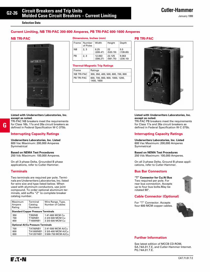
CAT.71.01.T.E
Cutler-HammerJanuary 1999
G2-26
G
Circuit Breakers and Trip UnitsMolded Case Circuit Breakers – Current LimitingSelection Data
Listed with Underwriters Laboratories, Inc. except as noted.TRI-PAC PB breakers meet the requirements for Class 17a and 26a circuit breakers as defined in Federal Specification W-C-375b.
Interrupting Capacity Ratings
Underwriters Laboratories, Inc. Listed600 Vac Maximum: 200,000 Amperes Symmetrical
Based on NEMA Test Procedures250 Vdc Maximum: 100,000 Amperes.
On all 3-phase Delta, Ground B phase appli-cations, refer to Cutler-Hammer.
Bus Bar Connectors
“T” Connector for Cu/Al BusTwo required per pole. Forrear bus connection. Acceptsup to four bus bolts.May be rotated 90°.
Cable Connector (Optional)
For “T” Connector. Accepts four 600 MCM copper cables.
Listed with Underwriters Laboratories, Inc. except as noted.TRI-PAC NB breakers meet the requirements for Class 16b, 17a and 26a circuit breakers as defined in Federal Specification W-C-375b.
Interrupting Capacity Ratings
Underwriters Laboratories, Inc. Listed600 Vac Maximum: 200,000 Amperes Symmetrical
Based on NEMA Test Procedures250 Vdc Maximum: 100,000 Amperes.
On all 3-phase Delta, Grounded B phase applications, refer to Cutler-Hammer.
Terminals
Two terminals are required per pole. Termi-nals are Underwriters Laboratories, Inc. listed for wire size and type listed below. When used with aluminum conductors, use joint compound. To order optional aluminum ter-minals, add suffix “Z” to complete breaker catalog number.
Maximum AmpereRating
Terminal Catalog Numbers
Wire Range, Type, Number of Cables
Standard Copper Pressure Terminals
350700800
T350NBT700NB1T1000NB1
1 #1-600 MCM Cu2 2/0-500 MCM Cu3 3/0-500 MCM Cu
Optional Al/Cu Pressure Terminals
700800800
TA700NB1TA1000NB1TA1201NB1
2 #1-500 MCM Al/Cu3 3/0-400 MCM Al/Cu3 500-750 MCM Al/Cu
Dimensions, Inches (mm)
Frame Number of Poles
Width Height Depth
NB 2, 3 8.25 (209.47)
22 (533.19)
5.5 (139.65)
PB 2, 3 12.063 (306.27)
22.125 (561.75)
9.063 (230.10)
Thermal-Magnetic Trip Ratings
Frame Ratings
NB TRI-PAC 300, 350, 400, 500, 600, 700, 800
PB TRI-PAC 600, 700, 800, 900, 1000, 1200,1400, 1600
NB TRI-PAC PB TRI-PAC
Current Limiting, NB TRI-PAC 300-800 Amperes, PB TRI-PAC 600-1600 Amperes
Further Information
See latest edition of MCCB CD-ROM, SA.74A.01.T.E, and Cutler-Hammer Internet.PG.74A.01.T.E.
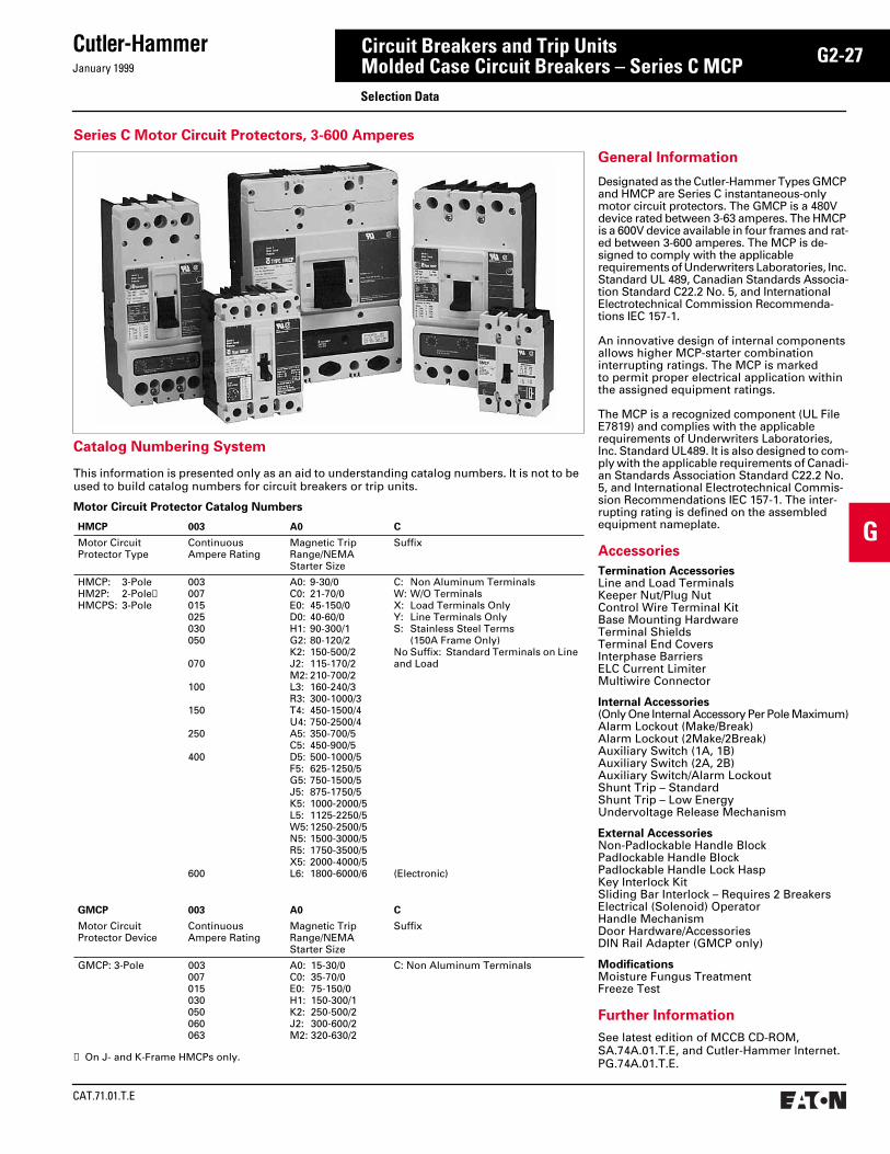
January 1999
Cutler-Hammer
CAT.71.01.T.E
G2-27
G
Circuit Breakers and Trip UnitsMolded Case Circuit Breakers – Series C MCPSelection Data
General Information
Designated as the Cutler-Hammer Types GMCP and HMCP are Series C instantaneous-only motor circuit protectors. The GMCP is a 480V device rated between 3-63 amperes. The HMCP is a 600V device available in four frames and rat-ed between 3-600 amperes. The MCP is de-signed to comply with the applicable requirements of Underwriters Laboratories, Inc. Standard UL 489, Canadian Standards Associa-tion Standard C22.2 No. 5, and International Electrotechnical Commission Recommenda-tions IEC 157-1.
An innovative design of internal components allows higher MCP-starter combination interrupting ratings. The MCP is marked to permit proper electrical application within the assigned equipment ratings.
The MCP is a recognized component (UL File E7819) and complies with the applicable requirements of Underwriters Laboratories, Inc. Standard UL489. It is also designed to com-ply with the applicable requirements of Canadi-an Standards Association Standard C22.2 No. 5, and International Electrotechnical Commis-sion Recommendations IEC 157-1. The inter-rupting rating is defined on the assembled equipment nameplate.
Accessories
Termination AccessoriesLine and Load TerminalsKeeper Nut/Plug NutControl Wire Terminal KitBase Mounting HardwareTerminal ShieldsTerminal End CoversInterphase BarriersELC Current LimiterMultiwire Connector
Internal Accessories(Only One Internal Accessory Per Pole Maximum)Alarm Lockout (Make/Break)Alarm Lockout (2Make/2Break)Auxiliary Switch (1A, 1B)Auxiliary Switch (2A, 2B)Auxiliary Switch/Alarm LockoutShunt Trip – StandardShunt Trip – Low EnergyUndervoltage Release Mechanism
External AccessoriesNon-Padlockable Handle BlockPadlockable Handle BlockPadlockable Handle Lock HaspKey Interlock KitSliding Bar Interlock – Requires 2 BreakersElectrical (Solenoid) OperatorHandle MechanismDoor Hardware/AccessoriesDIN Rail Adapter (GMCP only)
ModificationsMoisture Fungus TreatmentFreeze Test
Further Information
See latest edition of MCCB CD-ROM, SA.74A.01.T.E, and Cutler-Hammer Internet.PG.74A.01.T.E.
Catalog Numbering System
This information is presented only as an aid to understanding catalog numbers. It is not to be used to build catalog numbers for circuit breakers or trip units.
Motor Circuit Protector Catalog Numbers
HMCP 003 A0 C
Motor CircuitProtector Type
ContinuousAmpere Rating
Magnetic Trip Range/NEMA Starter Size
Suffix
HMCP: 3-PoleHM2P: 2-Pole➀HMCPS: 3-Pole
003007015025030050
070
100
150
250
400
600
A0: 9-30/0C0: 21-70/0E0: 45-150/0D0: 40-60/0H1: 90-300/1G2: 80-120/2K2: 150-500/2J2: 115-170/2M2: 210-700/2L3: 160-240/3R3: 300-1000/3T4: 450-1500/4U4: 750-2500/4A5: 350-700/5C5: 450-900/5D5: 500-1000/5F5: 625-1250/5G5: 750-1500/5J5: 875-1750/5K5: 1000-2000/5L5: 1125-2250/5W5: 1250-2500/5N5: 1500-3000/5R5: 1750-3500/5X5: 2000-4000/5L6: 1800-6000/6
C: Non Aluminum TerminalsW: W/O TerminalsX: Load Terminals OnlyY: Line Terminals OnlyS: Stainless Steel Terms
(150A Frame Only)No Suffix: Standard Terminals on Line and Load
(Electronic)
GMCP 003 A0 C
Motor CircuitProtector Device
ContinuousAmpere Rating
Magnetic Trip Range/NEMA Starter Size
Suffix
GMCP: 3-Pole 003007015030050060063
A0: 15-30/0C0: 35-70/0E0: 75-150/0H1: 150-300/1K2: 250-500/2J2: 300-600/2M2: 320-630/2
C: Non Aluminum Terminals
➀ On J- and K-Frame HMCPs only.
Series C Motor Circuit Protectors, 3-600 Amperes
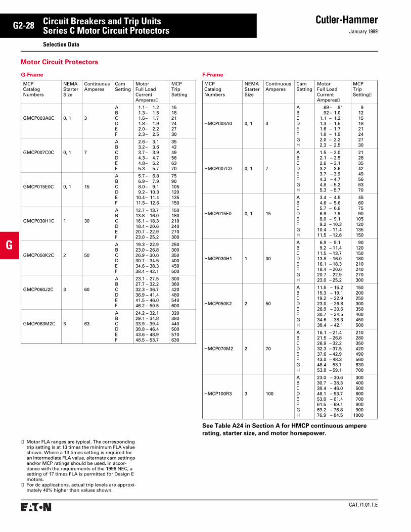
CAT.71.01.T.E
Cutler-HammerJanuary 1999
G2-28
G
Circuit Breakers and Trip UnitsSeries C Motor Circuit ProtectorsSelection Data
G-Frame
MCPCatalogNumbers
NEMAStarterSize
Continuous Amperes
CamSetting
MotorFull LoadCurrentAmperes➀
MCPTripSetting
GMCP003A0C 0, 1 3
ABCDEF
1.1 – 1.21.3 – 1.51.6 – 1.71.8 – 1.92.0 – 2.22.3 – 2.5
151821242730
GMCP007C0C 0, 1 7
ABCDEF
2.6 – 3.13.2 – 3.63.7 – 3.94.3 – 4.74.8 – 5.25.3 – 5.7
354249566370
GMCP015E0C 0, 1 15
ABCDEF
5.7 – 6.86.9 – 7.98.0 – 9.19.2 – 10.3
10.4 – 11.411.5 – 12.6
7590105120135150
GMCP030H1C 1 30
ABCDEF
12.7 – 13.713.8 – 16.016.1 – 18.318.4 – 20.620.7 – 22.923.0 – 25.2
150180210240270300
GMCP050K2C 2 50
ABCDEF
19.3 – 22.923.0 – 26.826.9 – 30.630.7 – 34.534.6 – 38.338.4 – 42.1
250300350400450500
GMCP060J2C 3 60
ABCDEF
23.1 – 27.527.7 – 32.232.3 – 36.736.9 – 41.441.5 – 46.046.2 – 50.5
300360420480540600
GMCP063M2C 3 63
ABCDEF
24.2 – 32.129.1 – 34.833.9 – 39.438.8 – 46.443.6 – 48.948.5 – 53.7
320380440500570630
See Table A24 in Section A for HMCP continuous ampere
rating, starter size, and motor horsepower.
F-Frame
MCPCatalogNumbers
NEMAStarterSize
Continuous Amperes
CamSetting
MotorFull LoadCurrentAmperes➀
MCPTripSetting➁
HMCP003A0 0, 1 3
ABCDEFGH
.69 – .91
.92 – 1.01.1 – 1.21.3 – 1.51.6 – 1.71.8 – 1.92.0 – 2.22.3 – 2.5
912151821242730
HMCP007C0 0, 1 7
ABCDEFGH
1.5 – 2.02.1 – 2.52.6 – 3.13.2 – 3.63.7 – 3.94.3 – 4.74.8 – 5.25.3 – 5.7
2128354249566370
HMCP015E0 0, 1 15
ABCDEFGH
3.4 – 4.54.6 – 5.65.7 – 6.86.9 – 7.98.0 – 9.19.2 – 10.3
10.4 – 11.411.5 – 12.6
45607590
105120135150
HMCP030H1 1 30
ABCDEFGH
6.9 – 9.19.2 – 11.4
11.5 – 13.713.8 – 16.016.1 – 18.318.4 – 20.620.7 – 22.923.0 – 25.2
90120150180210240270300
HMCP050K2 2 50
ABCDEFGH
11.5 – 15.215.3 – 19.119.2 – 22.923.0 – 26.826.9 – 30.630.7 – 34.534.6 – 38.338.4 – 42.1
150200250300350400450500
HMCP070M2 2 70
ABCDEFGH
16.1 – 21.421.5 – 26.826.9 – 32.232.3 – 37.537.6 – 42.943.0 – 48.348.4 – 53.753.8 – 59.1
210280350420490560630700
HMCP100R3 3 100
ABCDEFGH
23.0 – 30.630.7 – 38.338.4 – 46.046.1 – 53.753.8 – 61.461.5 – 69.169.2 – 76.876.9 – 84.5
300400500600700800900
1000
➀ Motor FLA ranges are typical. The corresponding trip setting is at 13 times the minimum FLA value shown. Where a 13 times setting is required for an intermediate FLA value, alternate cam settings and/or MCP ratings should be used. In accor-dance with the requirements of the 1996 NEC, a setting of 17 times FLA is permitted for Design E motors.
➁ For dc applications, actual trip levels are approxi-mately 40% higher than values shown.
Motor Circuit Protectors

January 1999
Cutler-Hammer
CAT.71.01.T.E
G2-29
G
Circuit Breakers and Trip UnitsSeries C Motor Circuit ProtectorsSelection Data
F-Frame, continued
MCPCatalogNumbers
NEMAStarterSize
Continuous Amperes
CamSetting
MotorFull LoadCurrentAmperes➀
MCPTripSetting➁
HMCP150T4 4 150
ABCDEFGH
34.6 – 46.046.1 – 57.557.6 – 69.169.2 – 80.680.7 – 92.292.3 – 103.7
103.8 – 115.2115.3 – 126.7
450600750900
1050120013501500
HMCP150U4 4 150
ABCDEFGH
57.0 – 75.076.0 – 95.096.0 – 114.0
115.0 – 130.7➂➂➂➂
7501000125015001750200022502500
See Table A24 in Section A for HMCP continuous ampere
rating, starter size, and motor horsepower.
MCPs for Application with Motor Starters Equipped with Electronic Overload Relays
MCPCatalogNumbers
NEMAStarterSize
Continuous Amperes
CamSetting
MotorFull LoadCurrentAmperes➀
MCPTripSetting➁
HMCPS003A0 0, 1 3
ABCDEFGH
.69 – .91
.92 – 1.01.1 – 1.21.3 – 1.51.6 – 1.71.8 – 1.92.0 – 2.22.3 – 2.5
912151821242730
HMCPS007C0 0, 1 7
ABCDEFGH
1.5 – 2.02.1 – 2.52.6 – 3.13.2 – 3.63.7 – 3.94.3 – 4.74.8 – 5.25.3 – 5.7
2128354249566370
HMCPS015E0C 0, 1 15
ABCDEFGH
3.4 – 4.54.6 – 5.65.7 – 6.86.9 – 7.98.0 – 9.19.2 – 10.3
10.4 – 11.411.5 – 12.6
45607590
105120135150
HMCPS030H1C 1 30
ABCDEFGH
6.9 – 9.19.2 – 11.4
11.5 – 13.713.8 – 16.016.1 – 18.318.4 – 20.620.7 – 22.923.0 – 25.2
90120150180210240270300
HMCPS050K2C 2 50
ABCDEFGH
11.5 – 15.215.3 – 19.119.2 – 22.923.0 – 26.826.9 – 30.630.7 – 34.534.6 – 38.338.4 – 42.1
150200250300350400450500
HMCPS100R3C 3 100
ABCDEFGH
23.0 – 30.630.7 – 38.338.4 – 46.046.1 – 53.753.8 – 61.461.5 – 69.169.2 – 76.876.9 – 84.5
300400500600700800900
1000
HMCP150T4C 4 150
ABCDEFGH
34.6 – 46.046.1 – 57.557.6 – 69.169.2 – 80.680.7 – 92.292.3 – 103.7
103.8 – 115.2115.3 – 126.7
450600750900
1050120013501500
HMCP150U4C 4 150
ABCDEFGH
57.0 – 75.076.0 – 95.096.0 – 114.0
115.0 – 130.7➂➂➂➂
7501000125015001750200022502500
➀ Motor FLA ranges are typical. The corresponding trip setting is at 13 times the minimum FLA value shown. Where a 13 times setting is required for an intermediate FLA value, alternate cam settings and/or MCP ratings should be used. In accordance with the requirements of the 1996 NEC, a setting of 17 times FLA is permitted for Design E motors.
➁ For Dc applications, actual trip levels are approximately 40% higher than values shown.
➂ Settings above 130 amps are for special applica-tions. NEC Article 430-110(a) requires the ampere rating of the disconnecting means to be not less than 115% of the motor full load ampere rating.
Motor Circuit Protectors
CAT.71.01.T.E
Cutler-HammerJanuary 1999
G2-30
G
Circuit Breakers and Trip UnitsSeries C Motor Circuit ProtectorsSelection Data
J-Frame
MCPCatalogNumbers➀
NEMAStarterSize
Continuous Amperes
CamSetting
MotorFull LoadCurrentAmperes➁
MCPTripSetting➂
HMCP250A5
444555555
250
ABCDEFGHI
27.0 – 30.730.8 – 33.833.9 – 36.937.0 – 40.340.4 – 43.843.9 – 46.947.0 – 50.750.8 – 53.853.9 – 57.2
350400440480525570610660700
HMCP250C5
555555555
250
ABCDEFGHI
34.7 – 38.838.9 – 43.443.5 – 47.647.7 – 52.252.3 – 56.556.6 – 60.760.8 – 64.965.0 – 69.269.3 – 73.5
450505565620680735790845900
HMCP250D5
555555555
250
ABCDEFGHI
38.5 – 43.443.5 – 48.048.1 – 53.053.1 – 57.657.7 – 62.362.4 – 67.367.4 – 71.972.0 – 76.977.0 – 81.6
500565625690750810875935
1000
HMCP250F5
555555555
250
ABCDEFGHI
48.1 – 53.853.9 – 59.960.0 – 66.166.2 – 72.372.4 – 78.478.5 – 83.883.9 – 89.990.0 – 96.196.2 – 102.0
625700780860940
1020109011701250
HMCP250G5
555555555
250
ABCDEFGHI
57.7 – 64.664.7 – 71.972.0 – 79.279.3 – 86.586.6 – 93.893.9 – 101.1
101.2 – 108.4108.5 – 115.3115.4 – 122.4
750840935
103011251220131514101500
See Table A24 in Section A for HMCP continuous ampere
rating, starter size, and motor horsepower.
MCPCatalogNumbers➀
NEMAStarterSize
Continuous Amperes
CamSetting
MotorFull LoadCurrentAmperes➁
MCPTripSetting➂
HMCP250J5
555555555
250
ABCDEFGHI
67.4 – 75.375.4 – 83.883.9 – 92.392.4 – 100.7
100.8 – 109.2109.3 – 117.6117.7 – 126.1126.2 – 134.6134.7 – 142.8
875980
1090120013101420153016401750
HMCP250K5
555555555
250
ABCDEFGHI
77.0 – 86.586.6 – 96.196.2 – 105.7
105.8 – 115.3115.4 – 124.9125.0 – 134.6134.7 – 144.2144.3 – 153.8153.9 – 163.3
100011251250137515001625175018752000
HMCP250L5
555555555
250
ABCDEFGHI
86.6 – 97.397.4 – 108.4
108.5 – 118.8118.9 – 129.9130.0 – 140.7140.8 – 151.5151.6 – 162.3162.4 – 173.0173.1 – 183.6
112512651410154516901830197021102250
HMCP250W5
555555555
250
ABCDEFGHI
96.2 – 108.0108.1 – 119.9120.0 – 132.3132.4 – 144.2144.3 – 156.1156.2 – 168.0168.1 – 179.9180.0 – 192.3192.4 – 204.0
125014051560172018752030218523402500
➀ Three-pole catalog numbers shown. Two-pole catalog numbers begin with “HM2P” in place of “HMCP”.
➁ Motor FLA ranges are typical. The corresponding trip setting is at 13 times the minimum FLA value shown. Where a 13 times setting is required for an intermediate FLA value, alternate cam settings and/or MCP ratings should be used. In accor-dance with the requirements of the 1996 NEC, a setting of 17 times FLA is permitted for Design E motors.
➂ For dc applications, actual trip levels are approximately 40% higher than values shown.
Motor Circuit Protectors
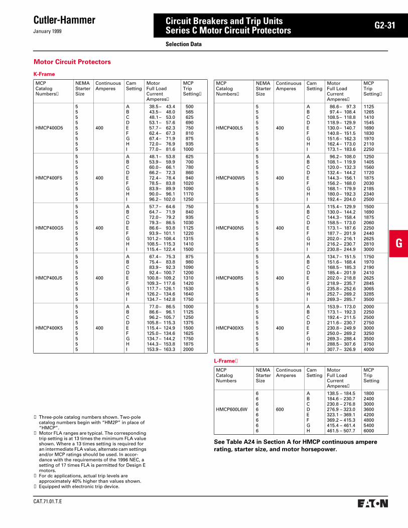
January 1999
Cutler-Hammer
CAT.71.01.T.E
G2-31
G
Circuit Breakers and Trip UnitsSeries C Motor Circuit ProtectorsSelection Data
K-Frame
MCPCatalogNumbers➀
NEMAStarterSize
Continuous Amperes
CamSetting
MotorFull LoadCurrentAmperes➁
MCPTripSetting➂
HMCP400D5
555555555
400
ABCDEFGHI
38.5 – 43.443.5 – 48.048.1 – 53.053.1 – 57.657.7 – 62.362.4 – 67.367.4 – 71.972.0 – 76.977.0 – 81.6
500565625690750810875935
1000
HMCP400F5
555555555
400
ABCDEFGHI
48.1 – 53.853.9 – 59.960.0 – 66.166.2 – 72.372.4 – 78.478.5 – 83.883.9 – 89.990.0 – 96.196.2 – 102.0
625700780860940
1020109011701250
HMCP400G5
555555555
400
ABCDEFGHI
57.7 – 64.664.7 – 71.972.0 – 79.279.3 – 86.586.6 – 93.893.9 – 101.1
101.2 – 108.4108.5 – 115.3115.4 – 122.4
750840935
103011251220131514101500
HMCP400J5
555555555
400
ABCDEFGHI
67.4 – 75.375.4 – 83.883.9 – 92.392.4 – 100.7
100.8 – 109.2109.3 – 117.6117.7 – 126.1126.2 – 134.6134.7 – 142.8
875980
1090120013101420153016401750
HMCP400K5
555555555
400
ABCDEFGHI
77.0 – 86.586.6 – 96.196.2 – 105.7
105.8 – 115.3115.4 – 124.9125.0 – 134.6134.7 – 144.2144.3 – 153.8153.9 – 163.3
100011251250137515001625175018752000
➀ Three-pole catalog numbers shown. Two-pole catalog numbers begin with “HM2P” in place of “HMCP”.
➁ Motor FLA ranges are typical. The corresponding trip setting is at 13 times the minimum FLA value shown. Where a 13 times setting is required for an intermediate FLA value, alternate cam settings and/or MCP ratings should be used. In accor-dance with the requirements of the 1996 NEC, a setting of 17 times FLA is permitted for Design E motors.
➂ For dc applications, actual trip levels are approximately 40% higher than values shown.
➃ Equipped with electronic trip device.
See Table A24 in Section A for HMCP continuous ampere
rating, starter size, and motor horsepower.
MCPCatalogNumbers➀
NEMAStarterSize
Continuous Amperes
CamSetting
MotorFull LoadCurrentAmperes➁
MCPTripSetting➂
HMCP400L5
555555555
400
ABCDEFGHI
86.6 – 97.397.4 – 108.4
108.5 – 118.8118.9 – 129.9130.0 – 140.7140.8 – 151.5151.6 – 162.3162.4 – 173.0173.1 – 183.6
112512651410154516901830197021102250
HMCP400W5
555555555
400
ABCDEFGHI
96.2 – 108.0108.1 – 119.9120.0 – 132.3132.4 – 144.2144.3 – 156.1156.2 – 168.0168.1 – 179.9180.0 – 192.3192.4 – 204.0
125014051560172018752030218523402500
HMCP400N5
555555555
400
ABCDEFGHI
115.4 – 129.9130.0 – 144.2144.3 – 158.4158.5 – 173.0173.1 – 187.6187.7 – 201.9202.0 – 216.1216.2 – 230.7230.8 – 244.9
150016901875206022502440262528103000
HMCP400R5
555555555
400
ABCDEFGHI
134.7 – 151.5151.6 – 168.4168.5 – 185.3185.4 – 201.9202.0 – 218.8218.9 – 235.7235.8 – 252.6252.7 – 269.2269.3 – 285.7
175019702190241026252845306532853500
HMCP400X5
555555555
400
ABCDEFGHI
153.9 – 173.0173.1 – 192.3192.4 – 211.5211.6 – 230.7230.8 – 249.9250.0 – 269.2269.3 – 288.4288.5 – 307.6307.7 – 326.9
200022502500275030003250350037504000
L-Frame➃
MCPCatalogNumbers
NEMAStarterSize
Continuous Amperes
CamSetting
MotorFull LoadCurrentAmperes➁
MCPTripSetting
HMCP600L6W
66666666
600
ABCDEFGH
138.5 – 184.5184.6 – 230.7230.8 – 276.8276.9 – 323.0323.1 – 369.1369.2 – 415.3415.4 – 461.4461.5 – 507.7
18002400300036004200480054006000
Motor Circuit Protectors

CAT.71.01.T.E
Cutler-HammerJanuary 1999
G2-32
G
Circuit Breakers and Trip UnitsMolded Case Circuit Breakers – Trip UnitsSelection Data
The Digitrip Family of Low-Voltage Electronic Trip Units
RMS 310 RMS 510 OPTIM 550➀ RMS 610 OPTIM 750 RMS 810 RMS 910 OPTIM 1050
RMS Sensing—5 Functions—Front Adjustable
RMS Sensing—9 Functions—Front Adjustable—Zone Selective Interlocking
RMS Sensing—10 Functions—Programmable—Load Monitoring—Diagnostics
RMS Sensing—9 Functions—Front Adjustable—Zone Selective Interlocking—Load Monitoring—Diagnostics
RMS Sensing—10 Functions—Programmable—Zone Selective Interlocking—Load Monitoring—Diagnostics—Communications
RMS Sensing—9 Functions—Front Adjustable—Zone Selective Interlocking—Load Monitoring—Diagnostics—Communications—Power and EnergyMonitoring
RMS Sensing—9 Functions—Front Adjustable—Zone Selective Interlocking—Load Monitoring—Diagnostics—Communications—Power and EnergyMonitoring—Harmonics
RMS Sensing—10 Functions—Programmable—Zone Selective Interlocking—Load Monitoring—Diagnostics—Communications—Power and EnergyMonitoring—Harmonics
General
Cutler-Hammer offers the most comprehen-sive range of electronic trip units in the indus-try for Molded Case Circuit Breakers. All electronic trip units are rms sensing and can be applied from 70 amperes up through 2500 amperes. Cutler-Hammer offers electronic trip units as standard for circuit breakers rated 800 amperes and above and offers electronic trip units as optional for circuit breakers 70 amperes up through 600 amperes.
Digitrip electronic trip units are ac devices that employ microprocessor-based technology that provides a true rms current sensing means for proper correlation with thermal characteristics of conductors and equipment. The primary function of the Digitrip electronic trip unit is to provide circuit protection. This is achieved by analyzing the secondary current signals received from the circuit breaker cur-rent sensors and initiating trip signals to the circuit breaker shunt trip when pre-set current levels and time delay settings are exceeded.
Electronic trip units are applied to distribution systems when high standards of protection and coordination are called for. In addition, electronic trip units can provide further enhanced features such as alarming, diagnos-tics, system monitoring, and communications.
Cutler-Hammer rms sensing trip units fall into two main categories:
● Front adjustable trip units (Digitrip RMS 310, 510, 610, 810, 910)
● Programmable trip units (Digitrip OPTIM 550, 750, and 1050)
Front Adjustable Trip UnitsFront adjustable trip units are electronic trip units that have up to nine time-current set-ting options that are set by switches mounted on the front of the trip unit. The application for front adjustable trip units would be distri-bution systems that can be coordinated with-in the range of settings available and that do not require sophisticated coordination strate-gies to be applied down through the distribu-tion system to small rated breakers.
Programmable Trip Units (OPTIM)Programmable trip units are electronic trip units that have up to ten time-current setting options that are programmed electronically by the use of a programming device. The application for programmable trip units would be high integrity distribution systems that require superior levels of system coordination coupled with system alarming, diagnostics and monitoring.
Rating PlugsRating plugs provide a means to establish the breaker’s continuous current rating. Rating plugs are color-coded and interchangeable to make it easy to match the correct rating plug with the correct trip unit. The same rating plug can be applied to both 50 and 60 Hz distribution systems. In general, most rating plugs are of the fixed ampere rating type. Cutler Hammer does offer an adjustable rating plug as an option for the Digitrip RMS 310 trip unit.
For detailed information on Trip Units, refer to section G3.
➀ Communications Kit available.
Electronic RMS Trip Unit

January 1999
Cutler-Hammer
CAT.71.01.T.E
G2-33
G
Circuit Breakers and Trip UnitsMolded Case Circuit Breakers – Trip UnitsSelection Data
➀ Adjust by Rating Plug➁ LS/LSG Only➂ Not to exceed 1200 Amperes➃ L and N Frames *20-100% x Is
R Frame *25-100% x In
BIM = Breaker Interface ModuleIs = Sensor RatingIn = Rating PlugIr = LDPU Setting x In(A) = GF Alarm
Molded Case Circuit Breaker Digitrip Selection Guide
Trip Unit
Type
Digitrip
RMS 310
Digitrip
RMS 510
Digitrip
OPTIM 550
Digitrip
RMS 610
Digitrip
OPTIM 750
Digitrip
RMS 810
Digitrip
RMS 910
Digitrip
OPTIM 1050
RMS Sensing Yes Yes Yes Yes Yes Yes Yes Yes
Breaker Type
Frame K, L, N, R R K, L, N R K, L, N, R R R K, L, N, R
Ampere Range 70A-2500A 800A-2500A 70A-2500A 800A-2500A 70A-2500A 800A-2500A 800A-2500A 70A-2500A
Interrupting Rating @ 480V 35, 65, 100 (kA) 65, 100 (kA) 35, 65, 100 (kA) 65, 100 (kA) 35, 65, 100 (kA) 65, 100 (kA) 65, 100 (kA) 35, 65, 100 (kA)
Protection
Ordering Options LSLSG
LSILSIG
LI, LS, LSI, LIG,LSG, LSIG
LSI, LSI(A), LSIG
LI, LS, LSI, LSG, LSIG
LSI(A), LSIG LI, LS, LSI, LIG,LSG, LSIG
LI, LS, LSI, LIG,LSG, LSIG
LSI(A), LISG
Fixed Rated Plug (In) Yes Yes Yes Yes Yes Yes Yes Yes
Overtemperature Trip Yes Yes Yes Yes Yes Yes Yes Yes
Long Delay Protection (L)
Adjustable Rating Plug (In) Yes No No No No No No No
Long Delay Pickup 0.5-1.0(In)➀ 0.5-1.0 x (In) 0.4-1.0 x (In) 0.5-1.0 x (In) 0.4-1.0 x (In) 0.5-1.0 x (In) 0.5-1.0 x (In) 0.4-1.0 x (In)
Long Delay Time I2T 12 Secs. 2-24 Secs. 2-24 Secs. 2-24 Secs. 2-24 Secs. 2-24 Secs. 2-24 Secs. 2-24 Secs.
Long Delay Time I4T No No 1-5 Secs. No 1-5 Secs. No No 1-5 Secs.
Long Delay Thermal Memory Yes Yes Yes Yes Yes Yes Yes Yes
High Load Alarm No No 0.5-1.0 x Ir 0.85 x Ir 0.5-1.0 x Ir 0.85 x Ir 0.85 x Ir 0.5-1.0 x IrShort Delay Protection (S)
Short Delay Pickup 200-800% x(In)
200-600%S1&S2 x (Ir)
150-800% x (Ir) 200-600%S1&S2 x (Ir)
150-800% x (Ir) 200-600%S1&S2 x (Ir)
200-600%S1&S2 x (Ir)
150-800% x (Ir)
Short Delay Time I2T 100ms No 100-500ms 100-500ms 100-500ms 100-500ms 100-500ms 100-500ms 100-500ms
Short Delay Time Flat No Inst-300ms 100-500ms 100-500ms 100-500ms 100-500ms 100-500ms 100-500ms 100-500ms
Short Delay Time Z.S.I. No Yes No Yes Yes Yes Yes Yes
Instantaneous Protection (I)
Instantaneous Pickup No 200-800% x (In)
200-600%M1&M2 x (In)
200-800% x (In) 200-600%M1&M2 x (In)
200-800% x (In) 200-600%M1&M2 x (In)
200-600%M1&M2 x (In)
200-800% x (In)
Discriminator No Yes ➁ Yes Yes ➁ Yes Yes ➁ Yes ➁ Yes
Instantaneous Override Yes Yes Yes Yes Yes Yes Yes Yes
Ground Fault Protection (G)
Ground Fault Alarm No No 20/25-100%➂ No 20/25-100%➂➃ No No 20/25-100%➂➃
Ground Fault Pickup Var/Frame➂ 25-100% x In➂ 20/25-100%➂ 25-100% x In➂ 20/25-100%➂➃ 25-100% x In➂ 25-100% x In➂ 20/25-100%➂➃
Ground Fault Delay I2T No 100-500ms 100-500ms 100-500ms 100-500ms 100-500ms 100-500ms 100-500ms
Ground Fault Delay Flat Inst-500ms 100-500ms 100-500ms 100-500ms 100-500ms 100-500ms 100-500ms 100-500ms
Ground Fault Z.S.I. No Yes No Yes Yes Yes Yes Yes
Ground Fault Thermal Memory Yes Yes Yes Yes Yes Yes Yes Yes
System Diagnostics
Cause of Trip Leds No Yes Yes Yes Yes Yes Yes Yes
Magnitude of Trip Information No No Yes Yes Yes Yes Yes Yes
Remote Signal Contacts No No No Yes Yes Yes Yes Yes
System Monitoring
Digital Display No No Yes➄ Yes Yes➄ Yes Yes Yes➄
Current No No Yes Yes Yes Yes Yes Yes
Voltage No No No No No No Yes No
Power and Energy No➅ No No No No Yes Yes Yes
Power Quality-Harmonics No No No No No No Yes Yes
Power Factor No No No No No Yes(Over IMPACC Only)
Yes Yes
Communications
IMPACC No No Optional➆ No Yes Yes Yes Yes
Testing
Testing Method Test Set Integral OPTIMizer,BIM, IMPACC➆
Integral OPTIMizer,BIM, IMPACC
Integral Integral OPTIMizer,BIM, IMPACC
➄ By OPTIMizer/BIM➅ Yes with addition of Energy Sentinel➆ Must install IMPACC Communications Kit as field
upgrade

CAT.71.01.T.E
Cutler-HammerJanuary 1999
G2-34
G
Circuit Breakers and Trip UnitsMolded Case Circuit Breakers Accessories and Modifications
Auxiliary SwitchThe auxiliary switch provides circuit breaker contact status information by monitoring the position of the molded crossbar containing the moving contact arms. The auxiliary switch is used for remote signaling and inter-locking purposes, and consists of one or two SPDT switches assembled to a plug-in mod-ule mounted in retaining slots in the top of the trip unit. Each SPDT switch has one “a” and one “b” contact. When the circuit breaker contacts are open, the ”a“ contact is open and the “b” contact is closed.
Shunt TripThe shunt trip provides remote controlled tripping of the circuit breaker. The shunt trip consists of an intermittent rated solenoid with a tripping plunger and a cutoff switch assem-bled to a plug-in module. When required for ground fault protection applications, certain ac rated shunt trips are suitable for operation at 55 percent of rated voltage.
Available in most Ac and Dc voltages
Notes: Approximate unlatching time—6 milliseconds. Approximate total circuit breaker contact opening time—18 millisec-onds. Endurance—4000 electrical operations plus 1000 mechanical operations. Supply volt-ages suitable for use with Class 1 GFP devices. Marking label included with accessory kits.
Typical Internal Plug-in Accessory Installed in K-frame Circuit Breaker
Different accessory wiring options are avail-able to satisfy most circuit breaker mounting applications. The standard wiring configura-tion is pigtail leads exiting the rear of the base directly behind the accessory. Optional con-figurations include a terminal block mounted on the same side of the base as the accessory, leads exiting the side of the base where the accessory is mounted, and leads exiting the rear of the base on the side opposite the accessory. If accessory leads longer than 18 inches are required, side-mounted terminal blocks should be used.
Internal Accessories
All internal accessories are of the plug-in type and are listed for field installation under UL File E64983.➀ Internal accessories for sealed circuit breakers are listed under UL File E7819➀ for factory installation only. The available plug-in accessories include the following:
● Alarm (Signal)/Lockout Switch● Auxiliary Switch● Shunt Trip● Low Energy Shunt Trip● Undervoltage Release Mechanism
Alarm (Signal)/Lockout SwitchThe alarm (signal)/lockout switch monitors circuit breaker trip status and provides remote signaling and interlocking capabilities when the circuit breaker trips. For 2-, 3-, and 4-pole circuit breakers, the alarm (signal)/lockout switch consists of one or two SPDT switches assembled to a plug-in module mounted in retaining slots in the top of the trip unit. The SPDT switch contacts are identi-fied as make and break contacts. When the circuit breaker trips, the make contact closes and the break contact opens.
➀ Some UL listings pending: refer to Cutler-Hammer.
Make
Break
a
b
ST
a
IMPACC Communications KitThe IMPACC Communications Kit provides the option to field install IMPACC communi-cations into a K-, L-, or N-frame OPTIM 550 breaker.

January 1999
Cutler-Hammer
CAT.71.01.T.E
G2-35
G
Circuit Breakers and Trip UnitsMolded Case Circuit Breakers Accessories and Modifications
STLE
Low Energy Shunt TripLow energy shunt trip devices are designed to operate from low energy output signals from dedicated current sensors typically applied in ground fault protection schemes. However, with a proper control voltage source, they may be applied in place of conventional trip devices for special applications. Flux paths surround-ing permanent magnets used in the shunt trip assembly hold a charged spring poised in readiness to operate the circuit breaker trip
Undervoltage Release MechanismThe undervoltage release mechanism moni-tors a voltage (typically a line voltage) and trips the circuit breaker when the voltage falls to between 70 and 35 percent of the solenoid coil rating.
The undervoltage release mechanism con-sists of a continuous rated solenoid with a plunger and tripping lever assembled to a plug-in module. The tab on the tripping lever
mechanism. When a 100 microfarad capacitor charged to 28 Vdc is discharged through the shunt trip coil, the resultant flux opposes the permanent magnet flux field, which releases the stored energy in the spring to trip the cir-cuit breaker. As the circuit breaker resets, the reset arm is actuated by the circuit breaker handle, resetting the shunt trip. The plug-in module is mounted in retaining slots in the top of the trip unit. Coil is intermittent-rated only. Cutoff provisions required in control circuit.
resets the undervoltage release mechanism when normal voltage has been restored and the circuit breaker handle is moved to the reset (OFF) position. With no voltage applied to the undervoltage release mechanism, the circuit breaker contacts will not touch when a closing operation is attempted.
Note: Undervoltage release mechanism accessories are not designed for, and should not be used as, circuit interlocks.
UV
Non-Padlockable Handle BlockThe nonlockable handle block secures the circuit breaker handle in either the ON or OFF position. (Trip-free operation allows the circuit breaker to trip when the handle block holds the circuit breaker handle in the ON position.) The device is positioned over the circuit breaker handle and secured by a
setscrew to deter accidental operation of the circuit breaker handle. (Field installation only.)
Padlockable Handle Lock HaspThe padlockable handle lock hasp allows the handle to be locked in the ON or OFF position. (Trip-free operation allows the circuit breaker to trip when the handle lock holds the circuit breaker handle in the ON position.) The hasp mounts on the circuit breaker cover within
Key Interlock Kit (Lock Not Included)The key interlock is used to externally lock the circuit breaker handle in the OFF position. When the key interlock is locked, an extended deadbolt blocks movement of the circuit breaker handle. Uniquely coded keys are removable only with the deadbolt extended. Each coded key controls a group of circuit breakers for a given specific customer installation.
the trimline. The cover is predrilled on both sides of the operating handle so that the hasp can be mounted on either side of the handle. The hasp will accommodate up to three pad-locks with1/4-inch (6mm) shackles. One per circuit breaker. (Field installation only.)
The key interlock assembly consists of a mounting kit and a purchaser supplied deadbolt lock. The mounting kit comprises a mounting plate, which is secured to the circuit breaker cover in either the left- or right-pole position; key interlock mounting hardware; and a wire seal. Specific mounting kits are required for individual key interlock types. (Field installation only.)
Padlockable Handle BlockThe device is positioned in the cover opening to prevent handle movement. Will accommo-date one 5⁄16-inch padlock.
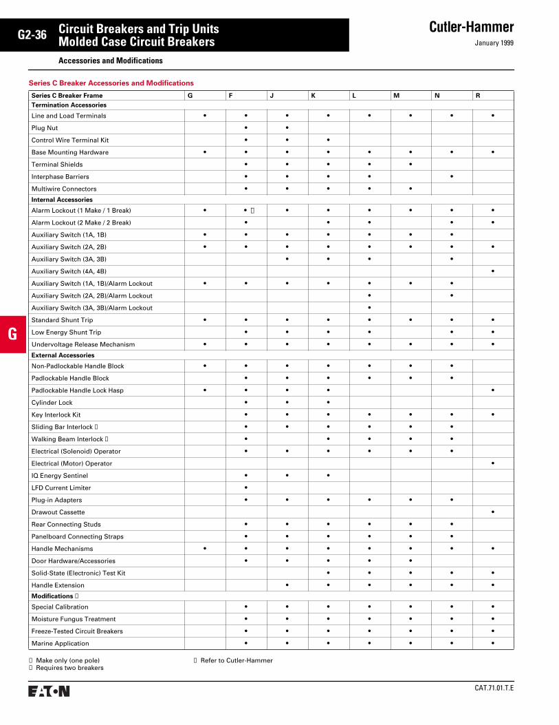
CAT.71.01.T.E
Cutler-HammerJanuary 1999
G2-36
G
Circuit Breakers and Trip UnitsMolded Case Circuit BreakersAccessories and Modifications
➀ Make only (one pole)➁ Requires two breakers
Series C Breaker Accessories and Modifications
Series C Breaker Frame G F J K L M N R
Termination Accessories
Line and Load Terminals • • • • • • • •Plug Nut • •Control Wire Terminal Kit • • •Base Mounting Hardware • • • • • • • •Terminal Shields • • • • •Interphase Barriers • • • • •Multiwire Connectors • • • • •Internal Accessories
Alarm Lockout (1 Make / 1 Break) • • ➀ • • • • • •Alarm Lockout (2 Make / 2 Break) • • • • •Auxiliary Switch (1A, 1B) • • • • • • •Auxiliary Switch (2A, 2B) • • • • • • • •Auxiliary Switch (3A, 3B) • • • •Auxiliary Switch (4A, 4B) •Auxiliary Switch (1A, 1B)/Alarm Lockout • • • • • • •Auxiliary Switch (2A, 2B)/Alarm Lockout • •Auxiliary Switch (3A, 3B)/Alarm Lockout •Standard Shunt Trip • • • • • • • •Low Energy Shunt Trip • • • • • •Undervoltage Release Mechanism • • • • • • • •External Accessories
Non-Padlockable Handle Block • • • • • • •Padlockable Handle Block • • • • • •Padlockable Handle Lock Hasp • • • • •Cylinder Lock • • •Key Interlock Kit • • • • • • •Sliding Bar Interlock ➁ • • • • • •Walking Beam Interlock ➁ • • • • •Electrical (Solenoid) Operator • • • • • •Electrical (Motor) Operator •IQ Energy Sentinel • • •LFD Current Limiter • Plug-in Adapters • • • • • •Drawout Cassette •Rear Connecting Studs • • • • • •Panelboard Connecting Straps • • • • • •Handle Mechanisms • • • • • • • •Door Hardware/Accessories • • • • •Solid-State (Electronic) Test Kit • • • • •Handle Extension • • • • • •Modifications ➂
Special Calibration • • • • • • •Moisture Fungus Treatment • • • • • • •Freeze-Tested Circuit Breakers • • • • • • •Marine Application • • • • • • •
➂ Refer to Cutler-Hammer
January 1999
Cutler-Hammer
CAT.71.01.T.E
G2-37
G
Circuit Breakers and Trip UnitsMolded Case Circuit Breakers Application Information
Circuit Voltage
Molded case circuit breakers are rated by voltage class and should be applied only to system voltages within their rating. The volt-age rating is determined by the maximum voltage that can be applied across its termi-nals, the type of distribution system and how the breaker is applied in the system.
Note: On all three-phase Delta, grounded B Phase applications, refer to Cutler-Hammer.
Circuit Frequency
The tripping characteristics of most molded case circuit breakers remain virtually constant when applied to frequencies of 50 and 60 hertz. On higher frequency applications, molded case circuit breakers must usually be specially calibrated and/or derated. The amount of derating depends upon the frame size and ampere rating as well as the current frequency. In general, the higher the ampere rating in a given frame size, the greater the derating required.
Thermal magnetic molded case circuit break-ers applied at frequencies above 60 hertz could require that individual consideration be given to thermal performance, magnetic performance and interrupting capabilities.
Electronic trip units are usually calibrated for 50/60 hertz, although operation at higher frequencies is achievable with the use of special derating factors and specially sized cable or bus.
Avoid making circuit breaker performance assumptions on applications above 60 hertz. Consult Cutler-Hammer for any Cutler-Hammer molded case circuit breaker above 60 hertz.
Continuous Ampere Rating
Molded case circuit breakers are rated in rms amperes at a specific ambient. This ampere rating is the continuous current they will carry in the ambient temperature for which they are calibrated. Cutler-Hammer thermal magnetic breakers are calibrated for an ambient tem-perature 40°C (104°F) which is the average temperature within an enclosure; thus, they minimize the need for derating. If the enclo-sure ambient is known to exceed 40°C, the breaker used should either be especially cali-brated for that ambient, or be derated accord-ingly. (Refer to item 9, Unusual Operating Conditions, for specific information.)
The selection of a specific ampere rating for a given application is dependent upon the type of load and duty cycle, and is governed by the National Electric Code. In general, the N.E.C. requires overcurrent protection at the supply and at points where wire sizes are reduced. It further states that the conductors be protected in accordance with their current carrying capac-ity, but lists exceptions for applications such
as motor circuits where a larger rating is often required to override motor inrush currents.
Cable Selection
Note: UL listed circuit breakers rated 125A or less shall be marked as being suitable fo 60°C (140°F), 75°C (167°F) only or 60/75°C (140/167°F) wire. All Cutler-Hammer listed breakers rated 125A or less are marked 60/75°C. All UL listed circuit breakers rated over 125A are suit-able for 75°C conductors. Conductors rated for higher temperatures may be used, but must not be loaded to carry more current than the 75°C ampacity of that size conductor for equip-ment marked or rated 75°C or the 65°C ampac-ity of that size conductor for equipment marked or rated 65°C. However, the full 90°C ampacity may be used when applying derated factors, so long as the actual load does not exceed the lower of the derated ampacity or the 75°C or 60°C ampacity that applies.
Circuit Breaker Sizing Considerations
The following paragraphs outline pertinent information from the NEC according to the type of load and duty cycle.
A. ServiceA service includes the conductors and equip-ment for delivering electrical energy from the supply system to the wiring system of the premises served.
NEC Article 230 contains the many require-ments for services of 600 volts or less includ-ing the sizing, location and overcurrent protection of conductors, disconnect means, permissible number of disconnects, ground-ing of conductors, and ground fault protec-tion requirements of service equipment.
B. Feeder CircuitsA feeder is composed of the conductors of a wiring system between the service equipment or the generator switchboard of an isolated plant and the branch circuit overcurrent device.
NEC Article 220: Where a feeder supplies continuous loads or any combination of continuous and noncontinuous loads, the rating of the overcurrent device shall not be less than the noncontinuous load plus 125 percent of the continuous load.
Exception: Where the assembly including the overcurrent devices protecting the feeder(s) are listed for operation at 100 percent of their rating, neither the ampere rating of the over-current device nor the ampacity of the feeder conductors shall be less than the sum of the continuous load plus the noncontinuous load.
Only breakers listed for 100% application, and so labeled, can be applied under the excep-tion (for example, type CKD). Breakers with-out 100% application listing and label are applied under (B) above, or at 80% of rating.
NEC Article 430: Breakers for feeders having mixed loads; i.e., heating (lighting and heat appliances) and motors, should have ratings suitable for carrying the heating loads plus the capacity required by the motor loads.
NEC Article 430: Breakers for motor feeders shall have a rating not greater than the sum of the highest breaker rating of any of its branches and the full load currents of all other motors served by the feeder.
C. Branch CircuitsA branch circuit is the portion of a wiring sys-tem extending beyond the final overcurrent device protecting the circuit.
(1) Lighting Circuits (NEC Article 310): These are protected in accordance with the conduc-tor ratings as given. High wattage incandes-cent lamp loads may result in abnormally high inrush currents that must be taken into account to avoid nuisance tripping. The lamp manufacturer should be consulted for data relative to the inrush currents.
(2) Motor Circuits (NEC Article 430): Breakers are primarily intended for the protection of conductors, motor control apparatus and motors against short circuits and ground fault conditions.
On motor overloads, the motor overcurrent device will open the circuit before the correctly applied breaker. Currents higher than the locked rotor value will be interrupted by the breakers, protecting the circuit from these heavy fault currents. The breaker must not trip on normal starting.
While breakers may be applied for motor running overcurrent protection when the requirements of Article 430 of the NEC are met, these applications are not recommended for Cutler-Hammer breakers and, therefore, this discussion is confined to the use of a breaker as a circuit protector.
For many applications, particularly those where starting behavior if the motor is unknown, the NEC maximum rules are followed. Usually, lower rated breakers can be used successfully. This is further discussed under motor circuit application and motor application tables.
Motor Circuit Application (NEC Article 430): The breaker must have a continuous rating of not less than 115% of the motor full load current. Before applying a breaker, one should check to determine the effect of any of the following conditions: High ambient temperature, heating within breaker enclosure due to grouping of current consuming devices, frequent motor starting, and lengthy motor acceleration period.
Breaker Rating or Setting (NEC Article 430): The motor branch circuit overcurrent device shall be capable of the motor. The required protection shall be considered as being obtained when the overcurrent device has a
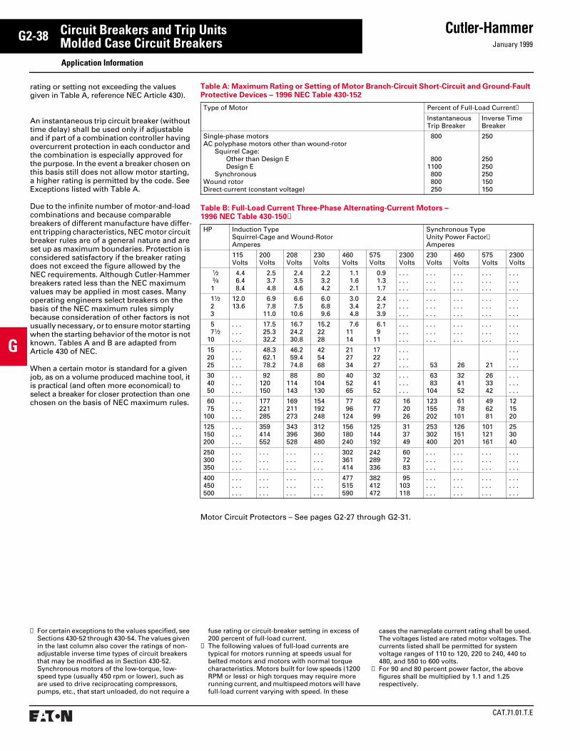
CAT.71.01.T.E
Cutler-HammerJanuary 1999
G2-38
G
Circuit Breakers and Trip UnitsMolded Case Circuit Breakers Application Information
rating or setting not exceeding the values given in Table A, reference NEC Article 430).
An instantaneous trip circuit breaker (without time delay) shall be used only if adjustable and if part of a combination controller having overcurrent protection in each conductor and the combination is especially approved for the purpose. In the event a breaker chosen on this basis still does not allow motor starting, a higher rating is permitted by the code. See Exceptions listed with Table A.
Due to the infinite number of motor-and-load combinations and because comparable breakers of different manufacture have differ-ent tripping characteristics, NEC motor circuit breaker rules are of a general nature and are set up as maximum boundaries. Protection is considered satisfactory if the breaker rating does not exceed the figure allowed by the NEC requirements. Although Cutler-Hammer breakers rated less than the NEC maximum values may be applied in most cases. Many operating engineers select breakers on the basis of the NEC maximum rules simply because consideration of other factors is not usually necessary, or to ensure motor starting when the starting behavior of the motor is not known. Tables A and B are adapted from Article 430 of NEC.
When a certain motor is standard for a given job, as on a volume produced machine tool, it is practical (and often more economical) to select a breaker for closer protection than one chosen on the basis of NEC maximum rules.
Table A: Maximum Rating or Setting of Motor Branch-Circuit Short-Circuit and Ground-Fault Protective Devices – 1996 NEC Table 430-152
Type of Motor Percent of Full-Load Current➀
Instantaneous Trip Breaker
Inverse Time Breaker
Single-phase motorsAC polyphase motors other than wound-rotor
Squirrel Cage:Other than Design EDesign E
SynchronousWound rotorDirect-current (constant voltage)
800
8001100 800 800 250
250
250250250150150
Motor Circuit Protectors – See pages G2-27 through G2-31.
Table B: Full-Load Current Three-Phase Alternating-Current Motors – 1996 NEC Table 430-150➁
HP Induction TypeSquirrel-Cage and Wound-RotorAmperes
Synchronous TypeUnity Power Factor➂Amperes
115 Volts
200Volts
208 Volts
230 Volts
460 Volts
575 Volts
2300 Volts
230 Volts
460 Volts
575 Volts
2300 Volts
1⁄2 3⁄4 1
4.4 6.4 8.4
2.5 3.7 4.8
2.4 3.5 4.6
2.2 3.2 4.2
1.1 1.6 2.1
0.9 1.3 1.7
. . .
. . .
. . .
. . .
. . .
. . .
. . .
. . .
. . .
. . .
. . .
. . .
. . .
. . .
. . .
11⁄2 2 3
12.013.6
6.9 7.8 11.0
6.6 7.5 10.6
6.0 6.8 9.6
3.0 3.4 4.8
2.4 2.7 3.9
. . .
. . .
. . .
. . .
. . .
. . .
. . .
. . .
. . .
. . .
. . .
. . .
. . .
. . .
. . .
5 71⁄2 10
. . .
. . .
. . .
17.5 25.3 32.2
16.7 24.2 30.8
15.2 22 28
7.6 11 14
6.1 9 11
. . .
. . .
. . .
. . .
. . .
. . .
. . .
. . .
. . .
. . .
. . .
. . .
. . .
. . .
. . .
15 20 25
. . .
. . .
. . .
48.3 62.1 78.2
46.2 59.4 74.8
42 54 68
21 27 34
17 22 27
. . .
. . .
. . . 53 26 21
. . .
. . .
. . .
30 40 50
. . .
. . .
. . .
92120150
88114143
80104130
40 52 65
32 41 52
. . .
. . .
. . .
63 83104
32 41 52
26 33 42
. . .
. . .
. . .
60 75100
. . .
. . .
. . .
177221285
169211273
154192248
77 96124
62 77 99
16 20 26
123155202
61 78101
49 62 81
121520
125150200
. . .
. . .
. . .
359414552
343396528
312360480
156180240
125144192
31 37 49
253302400
126151201
101121161
253040
250300350
. . .
. . .
. . .
. . .
. . .
. . .
. . .
. . .
. . .
. . .
. . .
. . .
302361414
242289336
60 72 83
. . .
. . .
. . .
. . .
. . .
. . .
. . .
. . .
. . .
. . .
. . .
. . .
400450500
. . .
. . .
. . .
. . .
. . .
. . .
. . .
. . .
. . .
. . .
. . .
. . .
477515590
382412472
95103118
. . .
. . .
. . .
. . .
. . .
. . .
. . .
. . .
. . .
. . .
. . .
. . .
➀ For certain exceptions to the values specified, see Sections 430-52 through 430-54. The values given in the last column also cover the ratings of non-adjustable inverse time types of circuit breakers that may be modified as in Section 430-52. Synchronous motors of the low-torque, low-speed type (usually 450 rpm or lower), such as are used to drive reciprocating compressors, pumps, etc., that start unloaded, do not require a
fuse rating or circuit-breaker setting in excess of 200 percent of full-load current.
➁ The following values of full-load currents are typical for motors running at speeds usual for belted motors and motors with normal torque characteristics. Motors built for low speeds (1200 RPM or less) or high torques may require more running current, and multispeed motors will have full-load current varying with speed. In these
cases the nameplate current rating shall be used. The voltages listed are rated motor voltages. The currents listed shall be permitted for system voltage ranges of 110 to 120, 220 to 240, 440 to 480, and 550 to 600 volts.
➂ For 90 and 80 percent power factor, the above figures shall be multiplied by 1.1 and 1.25 respectively.
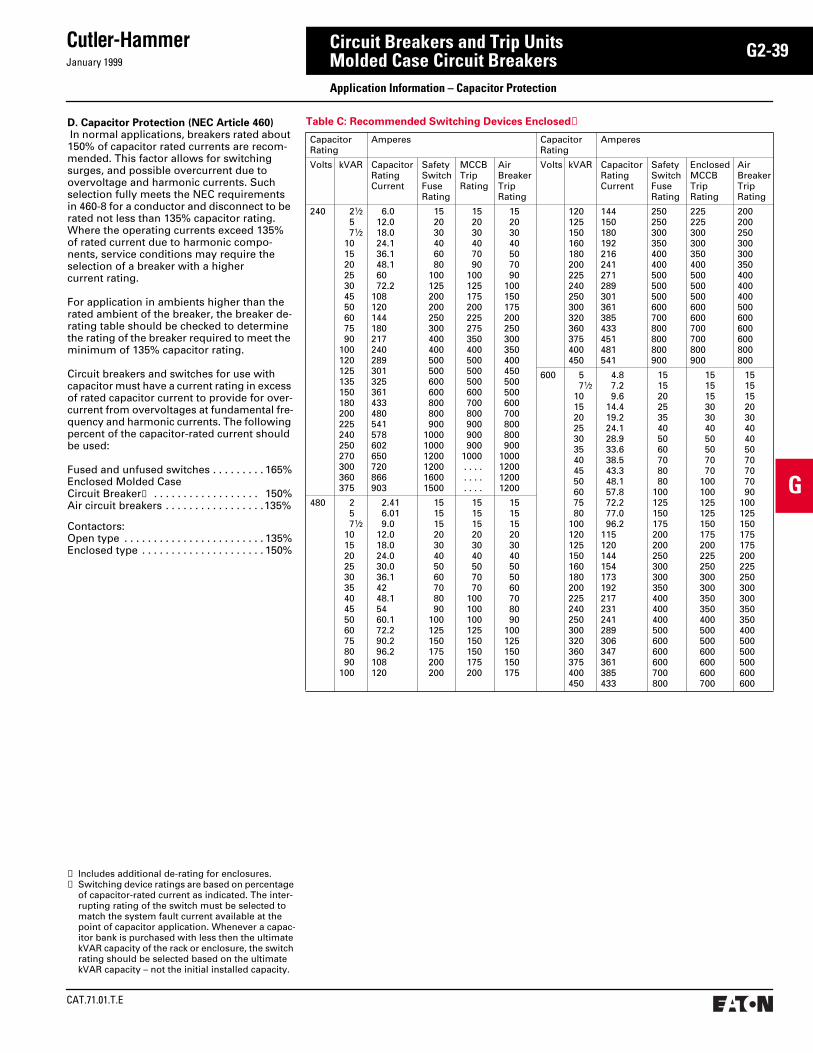
January 1999
Cutler-Hammer
CAT.71.01.T.E
G2-39
G
Circuit Breakers and Trip UnitsMolded Case Circuit Breakers Application Information – Capacitor Protection
D. Capacitor Protection (NEC Article 460) In normal applications, breakers rated about 150% of capacitor rated currents are recom-mended. This factor allows for switching surges, and possible overcurrent due to overvoltage and harmonic currents. Such selection fully meets the NEC requirements in 460-8 for a conductor and disconnect to be rated not less than 135% capacitor rating. Where the operating currents exceed 135% of rated current due to harmonic compo-nents, service conditions may require the selection of a breaker with a higher current rating.
For application in ambients higher than the rated ambient of the breaker, the breaker de-rating table should be checked to determine the rating of the breaker required to meet the minimum of 135% capacitor rating.
Circuit breakers and switches for use with capacitor must have a current rating in excess of rated capacitor current to provide for over-current from overvoltages at fundamental fre-quency and harmonic currents. The following percent of the capacitor-rated current should be used:
Fused and unfused switches . . . . . . . . . 165%Enclosed Molded Case Circuit Breaker➀ . . . . . . . . . . . . . . . . . . 150%Air circuit breakers . . . . . . . . . . . . . . . . .135%
Contactors:Open type . . . . . . . . . . . . . . . . . . . . . . . . 135%Enclosed type . . . . . . . . . . . . . . . . . . . . . 150%
➀ Includes additional de-rating for enclosures.➁ Switching device ratings are based on percentage
of capacitor-rated current as indicated. The inter-rupting rating of the switch must be selected to match the system fault current available at the point of capacitor application. Whenever a capac-itor bank is purchased with less then the ultimate kVAR capacity of the rack or enclosure, the switch rating should be selected based on the ultimate kVAR capacity – not the initial installed capacity.
Table C: Recommended Switching Devices Enclosed➁
CapacitorRating
Amperes CapacitorRating
Amperes
Volts kVAR CapacitorRatingCurrent
Safety SwitchFuse Rating
MCCBTrip Rating
Air BreakerTrip Rating
Volts kVAR CapacitorRatingCurrent
Safety SwitchFuse Rating
EnclosedMCCBTrip Rating
Air BreakerTrip Rating
240 21⁄2 5 71⁄2 10 15 20 25 30 45 50 60 75 90100120125135150180200225240250270300360375
6.0 12.0 18.0 24.1 36.1 48.1 60 72.2108120144180217240289301325361433480541578602650720866903
152030406080
100125200200250300400400500500600600800800900
100010001200120016001500
152030407090
100125175200225275350400500500500600700800900900900
1000. . . .. . . .. . . .
15203040507090
100150175200250300350400450500500600700800800900
1000120012001200
120125150160180200225240250300320360375400450
144150180192216241271289301361385433451481541
250250300350400400500500500600700800800800900
225225300300350400500500500600600700700800900
200200250300300350400400400500600600600800800
600 5 71⁄2 10 15 20 25 30 35 40 45 50 60 75 80100120125150160180200225240250300320360375400450
4.8 7.2 9.6 14.4 19.2 24.1 28.9 33.6 38.5 43.3 48.1 57.8 72.2 77.0 96.2115120144154173192217231241289306347361385433
1515202535405060708080
100125150175200200250300300350400400400500600600600700800
15151530304050507070
100100125125150175200225250300300350350400500500600600600700
151515203040405070707090
100125150175175200225250300300350350400500500500600600
480 2 5 71⁄2 10 15 20 25 30 35 40 45 50 60 75 80 90100
2.41 6.01 9.0 12.0 18.0 24.0 30.0 36.1 42 48.1 54 60.1 72.2 90.2 96.2108120
1515152030405060708090
100125150175200200
151515203040507070
100100100125150150175200
151515203040505060708090
100125150150175
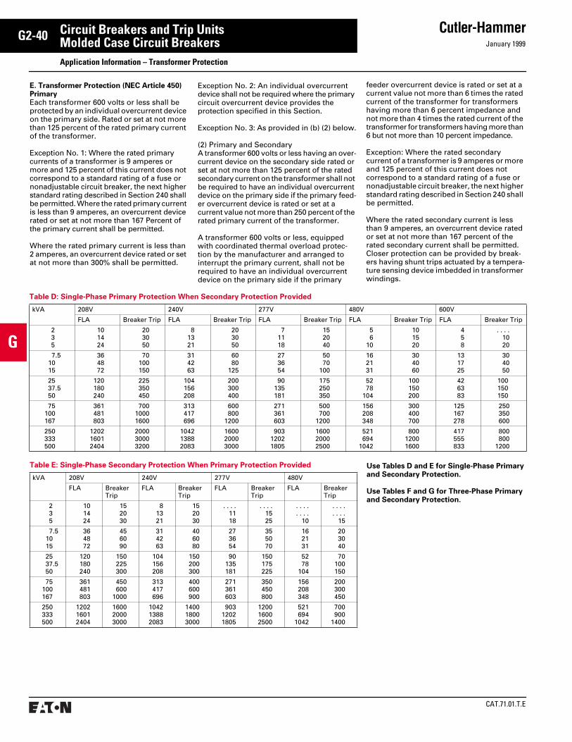
CAT.71.01.T.E
Cutler-HammerJanuary 1999
G2-40
G
Circuit Breakers and Trip UnitsMolded Case Circuit Breakers Application Information – Transformer Protection
Table D: Single-Phase Primary Protection When Secondary Protection Provided
kVA 208V 240V 277V 480V 600V
FLA Breaker Trip FLA Breaker Trip FLA Breaker Trip FLA Breaker Trip FLA Breaker Trip
235
101424
203050
81321
203050
71118
152040
56
10
101520
458
. . . .1020
7.5 10 15
364872
70100150
314263
6080
125
273654
5070
100
162131
304060
131725
304050
25 37.5 50
120180240
225350450
104156208
200300400
90135181
175250350
5278
104
100150200
426383
100150150
75100167
361481803
70010001600
313417696
600800
1200
271361603
500700
1200
156208348
300400700
125167278
250350600
250333500
120216012404
200030003200
104213882083
160020003000
90312021805
160020002500
521694
1042
80012001600
417555833
800800
1200
Use Tables D and E for Single-Phase Primary and Secondary Protection.
Use Tables F and G for Three-Phase Primary and Secondary Protection.
Table E: Single-Phase Secondary Protection When Primary Protection Provided
kVA 208V 240V 277V 480V
FLA Breaker Trip
FLA Breaker Trip
FLA Breaker Trip
FLA Breaker Trip
235
101424
152030
81321
152030
. . . .1118
. . . .1525
. . . .
. . . .10
. . . .
. . . .15
7.5 10 15
364872
456090
314263
406080
273654
355070
162131
203040
25 37.5 50
120180240
150225300
104156208
150200300
90135181
150175225
5278
104
70100150
75100167
361481803
450600
1000
313417696
400600900
271361603
350450800
156208348
200300450
250333500
120216012404
160020003000
104213882083
140018003000
90312021805
120016002500
521694
1042
700900
1400
E. Transformer Protection (NEC Article 450) PrimaryEach transformer 600 volts or less shall be protected by an individual overcurrent device on the primary side. Rated or set at not more than 125 percent of the rated primary current of the transformer.
Exception No. 1: Where the rated primary currents of a transformer is 9 amperes or more and 125 percent of this current does not correspond to a standard rating of a fuse or nonadjustable circuit breaker, the next higher standard rating described in Section 240 shall be permitted. Where the rated primary current is less than 9 amperes, an overcurrent device rated or set at not more than 167 Percent of the primary current shall be permitted.
Where the rated primary current is less than 2 amperes, an overcurrent device rated or set at not more than 300% shall be permitted.
Exception No. 2: An individual overcurrent device shall not be required where the primary circuit overcurrent device provides the protection specified in this Section.
Exception No. 3: As provided in (b) (2) below.
(2) Primary and SecondaryA transformer 600 volts or less having an over-current device on the secondary side rated or set at not more than 125 percent of the rated secondary current on the transformer shall not be required to have an individual overcurrent device on the primary side if the primary feed-er overcurrent device is rated or set at a current value not more than 250 percent of the rated primary current of the transformer.
A transformer 600 volts or less, equipped with coordinated thermal overload protec-tion by the manufacturer and arranged to interrupt the primary current, shall not be required to have an individual overcurrent device on the primary side if the primary
feeder overcurrent device is rated or set at a current value not more than 6 times the rated current of the transformer for transformers having more than 6 percent impedance and not more than 4 times the rated current of the transformer for transformers having more than 6 but not more than 10 percent impedance.
Exception: Where the rated secondary current of a transformer is 9 amperes or more and 125 percent of this current does not correspond to a standard rating of a fuse or nonadjustable circuit breaker, the next higher standard rating described in Section 240 shall be permitted.
Where the rated secondary current is less than 9 amperes, an overcurrent device rated or set at not more than 167 percent of the rated secondary current shall be permitted. Closer protection can be provided by break-ers having shunt trips actuated by a tempera-ture sensing device imbedded in transformer windings.
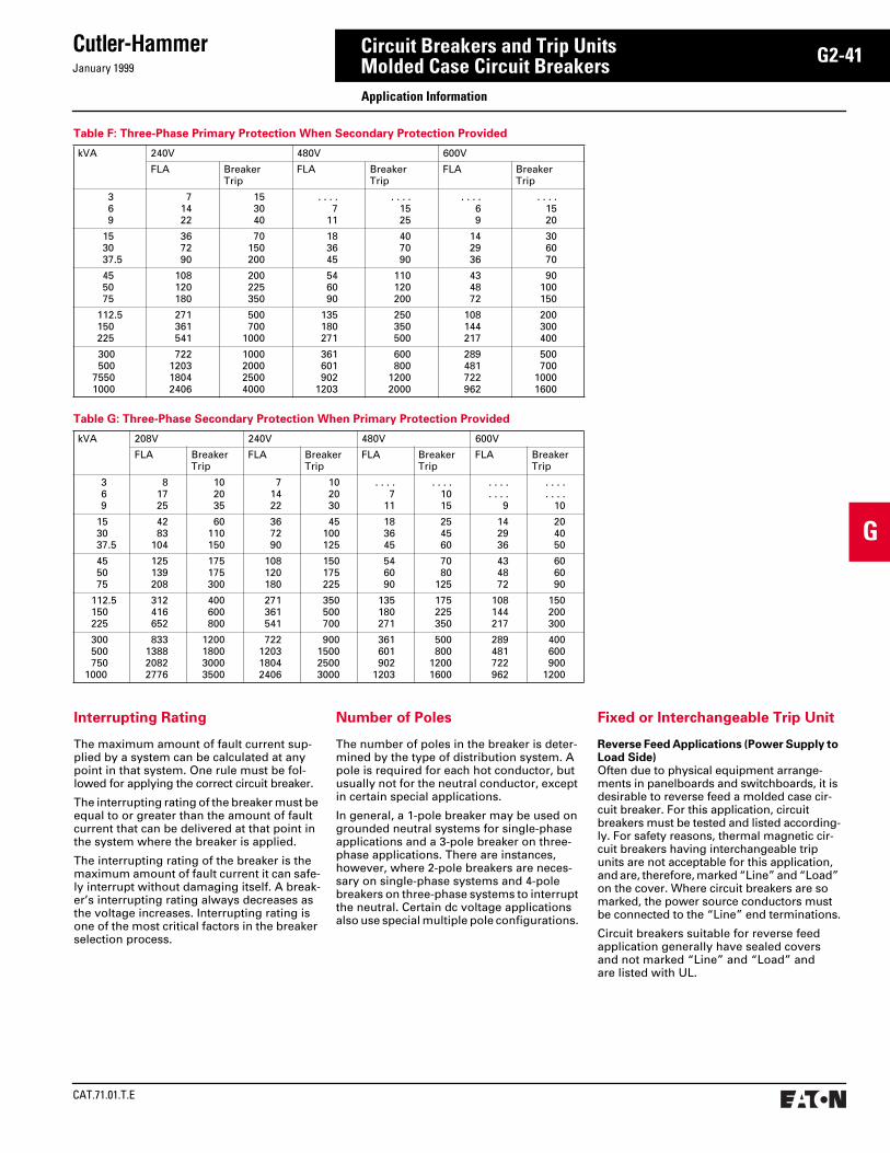
January 1999
Cutler-Hammer
CAT.71.01.T.E
G2-41
G
Circuit Breakers and Trip UnitsMolded Case Circuit Breakers Application Information
Table F: Three-Phase Primary Protection When Secondary Protection Provided
kVA 240V 480V 600V
FLA Breaker Trip
FLA Breaker Trip
FLA Breaker Trip
369
71422
153040
. . . .7
11
. . . .1525
. . . .69
. . . .1520
153037.5
367290
70150200
183645
407090
142936
306070
455075
108120180
200225350
546090
110120200
434872
90100150
112.5150225
271361541
500700
1000
135180271
250350500
108144217
200300400
300 50075501000
722120318042406
1000200025004000
361601902
1203
600800
12002000
289481722962
500700
10001600
Table G: Three-Phase Secondary Protection When Primary Protection Provided
kVA 208V 240V 480V 600V
FLA Breaker Trip
FLA Breaker Trip
FLA Breaker Trip
FLA Breaker Trip
369
81725
102035
71422
102030
. . . .7
11
. . . .1015
. . . .
. . . .9
. . . .
. . . .10
153037.5
4283
104
60110150
367290
45100125
183645
254560
142936
204050
455075
125139208
175175300
108120180
150175225
546090
7080
125
434872
606090
112.5150225
312416652
400600800
271361541
350500700
135180271
175225350
108144217
150200300
300500750
1000
833138820822776
1200180030003500
722120318042406
900150025003000
361601902
1203
500800
12001600
289481722962
400600900
1200
Interrupting Rating
The maximum amount of fault current sup-plied by a system can be calculated at any point in that system. One rule must be fol-lowed for applying the correct circuit breaker.
The interrupting rating of the breaker must be equal to or greater than the amount of fault current that can be delivered at that point in the system where the breaker is applied.
The interrupting rating of the breaker is the maximum amount of fault current it can safe-ly interrupt without damaging itself. A break-er’s interrupting rating always decreases as the voltage increases. Interrupting rating is one of the most critical factors in the breaker selection process.
Number of Poles
The number of poles in the breaker is deter-mined by the type of distribution system. A pole is required for each hot conductor, but usually not for the neutral conductor, except in certain special applications.
In general, a 1-pole breaker may be used on grounded neutral systems for single-phase applications and a 3-pole breaker on three- phase applications. There are instances, however, where 2-pole breakers are neces-sary on single-phase systems and 4-pole breakers on three-phase systems to interrupt the neutral. Certain dc voltage applications also use special multiple pole configurations.
Fixed or Interchangeable Trip Unit
Reverse Feed Applications (Power Supply to Load Side)Often due to physical equipment arrange-ments in panelboards and switchboards, it is desirable to reverse feed a molded case cir-cuit breaker. For this application, circuit breakers must be tested and listed according-ly. For safety reasons, thermal magnetic cir-cuit breakers having interchangeable trip units are not acceptable for this application, and are, therefore, marked “Line” and “Load” on the cover. Where circuit breakers are so marked, the power source conductors must be connected to the “Line” end terminations.
Circuit breakers suitable for reverse feed application generally have sealed covers and not marked “Line” and “Load” and are listed with UL.

CAT.71.01.T.E
Cutler-HammerJanuary 1999
G2-42
G
Circuit Breakers and Trip UnitsMolded Case Circuit Breakers Application Information
Unusual Operating Conditions
Trip Unit TemperaturesThermal magnetic circuit breakers are temper-ature sensitive. At ambient temperatures below 40°C, circuit breakers carry more current than their continuous current rating. Nuisance tripping is not a problem under these lower temperature conditions, although consider-ation should be given to closer protection coordination to compensate for the additional current carrying capability. In addition, the actual mechanical operation of the breaker could be affected if the ambient temperature is significantly below the 40°C standard.
For ambient temperatures above 40°C, break-ers will carry less current than their continu-ous current rating. This condition promotes nuisance tripping and can create unaccept-able temperature conditions at the terminals. Under this condition, the circuit breaker should be recalibrated for the higher ambient temperature.
Electronic trip units are insensitive to ambient temperatures within a certain temperature range. The temperature range for most Cutler- Hammer electronic trip units is -20°C to +55°C. However, at very low ambient temperatures, the mechanical parts of the breaker could require special treatment, such as the use of special lubricants. If the ambient temperature exceeds 40°C significantly, damage to the electronic circuitry and other components could result. Cutler-Hammer includes tempera-ture protective circuits in its designs to initiate a tripping operation and provide self-protection, should the internal temperature rise to an unsafe level.
It is always a good practice to consult the manufacturer when the normal operating ambient temperature is not 40°C.
Circuit Breaker TemperaturesThe temperature of the air surrounding a cir-cuit breaker is the ambient temperature. For some years, all molded case circuit breakers were calibrated for 25°C (77°F). This ambient temperature was not very representative of the conditions in which most molded case circuit breakers were applied, namely in an enclosure. In the mid-1960s, industry stan-dards were changed to make all standard breakers calibrated to a 40°C ambient temperature. For any ambient temperature application above or below 40°C, it is recom-mended that the breaker manufacturer be consulted as to any possible rerating, recalibration or special procedures, before the circuit breaker is selected and applied.
Moisture – CorrosionHigh moisture content and/or the presence of corrosive elements can result in damage to key operating components and/or severely compromise the breaker’s operational integ-rity. As is the case with all electrical equip-ment, this type of condition or environment should be avoided. Good electrical practice dictates that electrical equipment always be applied in a clean environment, free of mois-ture and corrosion. If such operating condi-tions can not be avoided, special treatment of the circuit breaker should be considered to minimize the possibility of operational prob-lems. Most Cutler-Hammer molded case circuit breaker cases are molded from glass polyester which does not support the growth of fungus. In addition, a special moisture and fungus-resisting treatment is recommended for any parts that are susceptible to the growth of fungus. In areas where daily temperature changes have a tendency to cause condensation, the inclusion of space heaters in the enclosure is the best preventa-tive measure. The manufacturer should be consulted if either one of these operational environments is likely to exist. Consider the addition of a Cutler-Hammer C799 series oxi-dation inhibiting capsule in the assembly.
AltitudeLow-voltage circuit breakers must be pro-gressively derated for voltage, current carry-ing and interrupting rating at altitudes above 6000 feet. The thinner air at higher altitudes reduces cooling and dielectric characteristics compared to the denser air found at lower altitudes. Refer to Cutler-Hammer for additional application details.
Shock/VibrationWhere high shock is an anticipated condition, hi-shock Navy type breakers are recommended. Molded case circuit breakers can be supplied to meet the following marine specifications: U.S. Coast Guard CFR 46, ABS – American Bureau of Shipping, IEEE 45, UL 489 Supplement SA Marine, and UL 489 Supplemental SB Naval.
Table H: Derating Chart for Non-Compensated Thermal Magnetic Breakers Calibrated for 40°C
Breaker AmpereRatingat 40°C
Ampere Rating
25°C(77°F)
50°C(122°F)
60°C(140°F)
F-Frame
15202530354050607090
100125150
17223233414555667799
110137165
1318212732344656658494
116138
1116162427294252607887
105125
J-Frame
7090
100125150175200225250
79102115140171200230252281
638189
114134156178205227
557176
102116134153183201
K-Frame
100125150175200225250300350400
121145188210243255294364412471
90116132159180212230270322368
79106111141157198208236291333
L-Frame
300350400500600
330385440550660
276325327468564
252301340435525
M-Frame
300350400450500600700800
332388444495550660770880
277322368418468564658754
252292334383435525613704
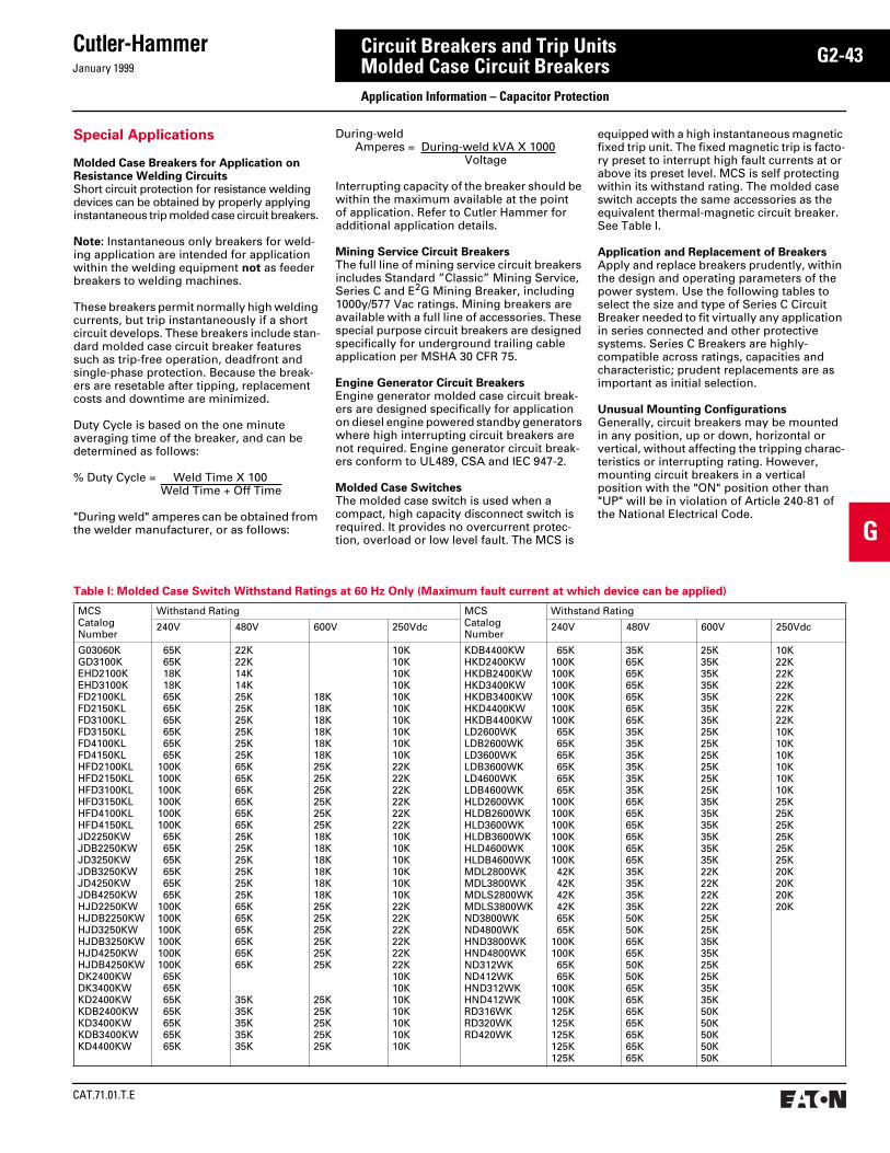
January 1999
Cutler-Hammer
CAT.71.01.T.E
G2-43
G
Circuit Breakers and Trip UnitsMolded Case Circuit Breakers Application Information – Capacitor Protection
Special Applications
Molded Case Breakers for Application on Resistance Welding CircuitsShort circuit protection for resistance welding devices can be obtained by properly applying instantaneous trip molded case circuit breakers.
Note: Instantaneous only breakers for weld-ing application are intended for application within the welding equipment not as feeder breakers to welding machines.
These breakers permit normally high welding currents, but trip instantaneously if a short circuit develops. These breakers include stan-dard molded case circuit breaker features such as trip-free operation, deadfront and single-phase protection. Because the break-ers are resetable after tipping, replacement costs and downtime are minimized. Duty Cycle is based on the one minute averaging time of the breaker, and can be determined as follows:
% Duty Cycle = Weld Time X 100 Weld Time + Off Time
"During weld" amperes can be obtained from the welder manufacturer, or as follows:
During-weld Amperes = During-weld kVA X 1000
Voltage
Interrupting capacity of the breaker should be within the maximum available at the point of application. Refer to Cutler Hammer for additional application details.
Mining Service Circuit BreakersThe full line of mining service circuit breakers includes Standard ”Classic” Mining Service, Series C and E2G Mining Breaker, including 1000y/577 Vac ratings. Mining breakers are available with a full line of accessories. These special purpose circuit breakers are designed specifically for underground trailing cable application per MSHA 30 CFR 75.
Engine Generator Circuit BreakersEngine generator molded case circuit break-ers are designed specifically for application on diesel engine powered standby generators where high interrupting circuit breakers are not required. Engine generator circuit break-ers conform to UL489, CSA and IEC 947-2.
Molded Case SwitchesThe molded case switch is used when a compact, high capacity disconnect switch is required. It provides no overcurrent protec-tion, overload or low level fault. The MCS is
equipped with a high instantaneous magnetic fixed trip unit. The fixed magnetic trip is facto-ry preset to interrupt high fault currents at or above its preset level. MCS is self protecting within its withstand rating. The molded case switch accepts the same accessories as the equivalent thermal-magnetic circuit breaker. See Table I.
Application and Replacement of Breakers Apply and replace breakers prudently, within the design and operating parameters of the power system. Use the following tables to select the size and type of Series C Circuit Breaker needed to fit virtually any application in series connected and other protective systems. Series C Breakers are highly-compatible across ratings, capacities and characteristic; prudent replacements are as important as initial selection.
Unusual Mounting ConfigurationsGenerally, circuit breakers may be mounted in any position, up or down, horizontal or vertical, without affecting the tripping charac-teristics or interrupting rating. However, mounting circuit breakers in a vertical position with the "ON" position other than "UP" will be in violation of Article 240-81 of the National Electrical Code.
Table I: Molded Case Switch Withstand Ratings at 60 Hz Only (Maximum fault current at which device can be applied)
MCSCatalogNumber
Withstand Rating MCSCatalogNumber
Withstand Rating
240V 480V 600V 250Vdc 240V 480V 600V 250Vdc
G03060KGD3100KEHD2100KEHD3100KFD2100KLFD2150KLFD3100KLFD3150KLFD4100KLFD4150KLHFD2100KLHFD2150KLHFD3100KLHFD3150KLHFD4100KLHFD4150KLJD2250KWJDB2250KWJD3250KWJDB3250KWJD4250KWJDB4250KWHJD2250KWHJDB2250KWHJD3250KWHJDB3250KWHJD4250KWHJDB4250KWDK2400KWDK3400KWKD2400KWKDB2400KWKD3400KWKDB3400KWKD4400KW
65K65K18K18K65K65K65K65K65K65K
100K100K100K100K100K100K65K65K65K65K65K65K
100K100K100K100K100K100K65K65K65K65K65K65K65K
22K22K14K14K25K25K25K25K25K25K65K65K65K65K65K65K25K25K25K25K25K25K65K65K65K65K65K65K
35K35K35K35K35K
18K18K18K18K18K18K25K25K25K25K25K25K18K18K18K18K18K18K25K25K25K25K25K25K
25K25K25K25K25K
10K10K10K10K10K10K10K10K10K10K22K22K22K22K22K22K10K10K10K10K10K10K22K22K22K22K22K22K10K10K10K10K10K10K10K
KDB4400KWHKD2400KWHKDB2400KWHKD3400KWHKDB3400KWHKD4400KWHKDB4400KWLD2600WKLDB2600WKLD3600WKLDB3600WKLD4600WKLDB4600WKHLD2600WKHLDB2600WKHLD3600WKHLDB3600WKHLD4600WKHLDB4600WKMDL2800WKMDL3800WKMDLS2800WKMDLS3800WKND3800WKND4800WKHND3800WKHND4800WKND312WKND412WKHND312WKHND412WKRD316WKRD320WKRD420WK
65K100K100K100K100K100K100K65K65K65K65K65K65K
100K100K100K100K100K100K42K42K42K42K65K65K
100K100K65K65K
100K100K125K125K125K125K125K
35K65K65K65K65K65K65K35K35K35K35K35K35K65K65K65K65K65K65K35K35K35K35K50K50K65K65K50K50K65K65K65K65K65K65K65K
25K35K35K35K35K35K35K25K25K25K25K25K25K35K35K35K35K35K35K22K22K22K22K25K25K35K35K25K25K35K35K50K50K50K50K50K
10K22K22K22K22K22K22K10K10K10K10K10K10K25K25K25K25K25K25K20K20K20K20K
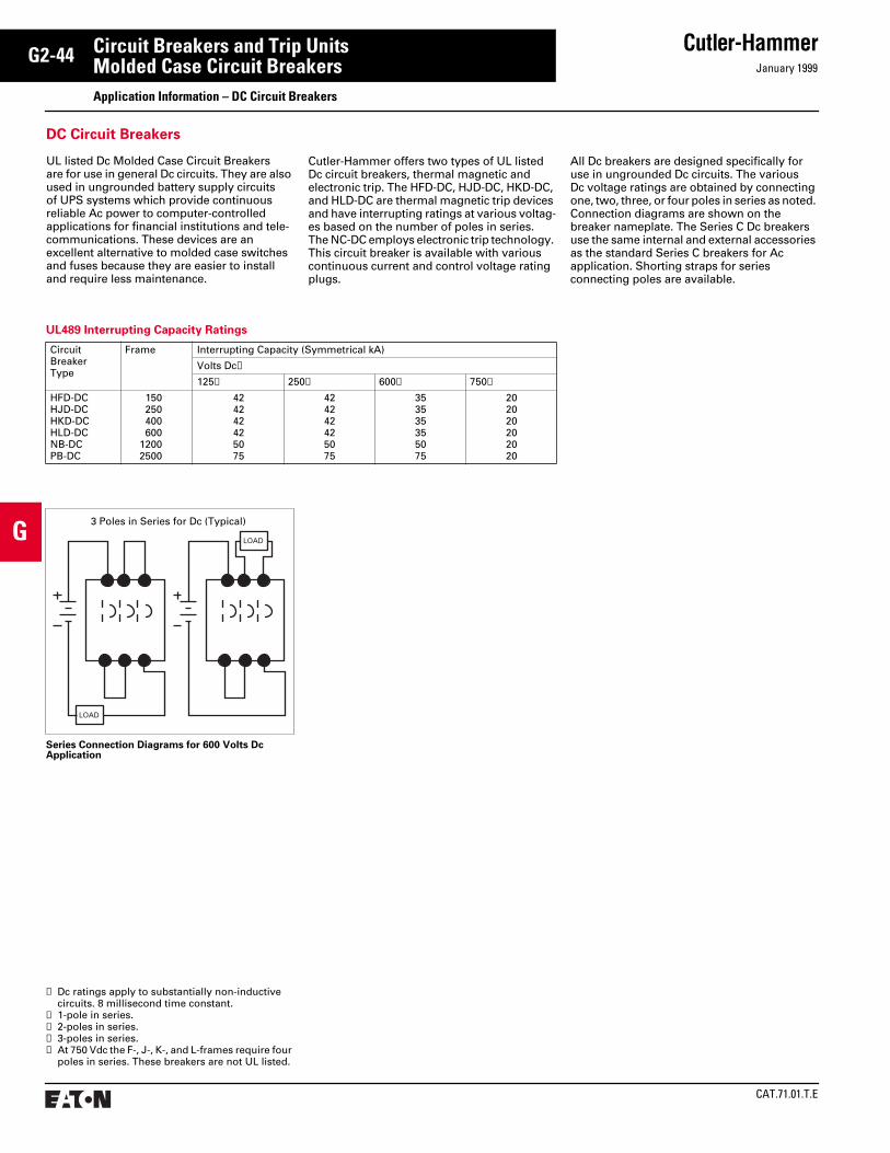
CAT.71.01.T.E
Cutler-HammerJanuary 1999
G2-44
G
Circuit Breakers and Trip UnitsMolded Case Circuit Breakers Application Information – DC Circuit Breakers
UL489 Interrupting Capacity Ratings
CircuitBreakerType
Frame Interrupting Capacity (Symmetrical kA)
Volts Dc➀
125➁ 250➂ 600➃ 750➄
HFD-DCHJD-DCHKD-DCHLD-DCNB-DCPB-DC
150 250 400 60012002500
424242425075
424242425075
353535355075
202020202020
LOAD
LOAD
3 Poles in Series for Dc (Typical)
DC Circuit Breakers
UL listed Dc Molded Case Circuit Breakers are for use in general Dc circuits. They are also used in ungrounded battery supply circuits of UPS systems which provide continuous reliable Ac power to computer-controlled applications for financial institutions and tele-communications. These devices are an excellent alternative to molded case switches and fuses because they are easier to install and require less maintenance.
Cutler-Hammer offers two types of UL listed Dc circuit breakers, thermal magnetic and electronic trip. The HFD-DC, HJD-DC, HKD-DC, and HLD-DC are thermal magnetic trip devices and have interrupting ratings at various voltag-es based on the number of poles in series. The NC-DC employs electronic trip technology. This circuit breaker is available with various continuous current and control voltage rating plugs.
All Dc breakers are designed specifically for use in ungrounded Dc circuits. The various Dc voltage ratings are obtained by connecting one, two, three, or four poles in series as noted. Connection diagrams are shown on the breaker nameplate. The Series C Dc breakers use the same internal and external accessories as the standard Series C breakers for Ac application. Shorting straps for series connecting poles are available.
Series Connection Diagrams for 600 Volts Dc Application
➀ Dc ratings apply to substantially non-inductive circuits. 8 millisecond time constant.
➁ 1-pole in series.➂ 2-poles in series.➃ 3-poles in series.➄ At 750 Vdc the F-, J-, K-, and L-frames require four
poles in series. These breakers are not UL listed.

January 1999
Cutler-Hammer
CAT.71.01.T.E
G2-45
G
Circuit Breakers and Trip UnitsMolded Case Circuit Breakers Application Information – 400-415 Hz
Table J: Continuous Current of 400 Hz Breakers
Breaker Frame Series Maximum Continuous Amperes at 60 Hz
400-415 Hz Application➀
Maximum Continuous Amperes
Terminals (Fixed Front) Catalog or Style Number
Cable/Bus Bar(Per Phase)
EHD, FDB, FD 15 20 25 30 35 40 50 70 90 100 125➁ 150➁
15 20 25 30 35 40 45 65 85 95 115 135
624B100G02624B100G02624B100G02624B100G02624B100G02624B100G02624B100G02624B100G02624B100G02624B100G17624B100G17624B100G17
1 #12 CU1 #12 CU1 #12 CU1 #10 CU1 #10 CU1 #8 CU1 #6 CU1 #4 CU1 #2 CU1 #1 CU1-1/0 CU1-1/0 CU
JDB, JD, HJD 70 90 100 125 150 175 200 225 250
60 80 90 100 125 150 160 200 200
T250KBT250KBT250KBT250KBT250KBT250KBT250KBT250KBT250KB
1 #4 CU1 #2 CU1 #1 CU1-1/0 CU1-1/0 CU1-2/0 CU1-3/0 CU1-4/0 CU1-250 MCM CU
KDB, KD, HKD 125 150 175 200 225 250 300 350 400
100 125 150 160 180 200 225 275 300
T300KT300KT300KT300KT300KT300KT300KT350KT400K
1-1/0 CU1-1/0 CU1-2/0 CU1-3/0 CU1-4/0 CU1-250 MCM CU1-350 MCM CU1-500 MCM CU2-3/0 CU
LDB, LD, HLD 250 300 350 400 500 600
210 240 275 310 370 425
T600LAT600LAT600LAT600LAT600LAT600LA
1-250 MCM CU1-350 MCM CU1-500 MCM CU2-250 MCM CU2-350 MCM CU2-500 MCM CU
LD With Digitrip RMS 310 300 600
300 500
T401LAT401LA
2-250 MCM CU2-350 MCM CU
MD With Digitrip RMS 310 400 500 600 700 800
340 405 470 355 400
601MAT601MAT601MAT601MAT601MA
2-3/0 CU2-300 MCM CU2-350 MCM CU2-4/0 CU2-300 MCM CU
ND With Digitrip RMS 310 1200 700 750 850
T1000 NBIT1000 NBIT1200 NBI
3-300 MCM CU3-350 MCM CU4-350 MCM CU
RD With Digitrip RMS 310 2000 1500 Rear Connected CU T-Bar. 41⁄2 x 4cu.
➀ The calibration of these breakers and the tolerance percentages of the time-current curves are the same as at 60 Hz.
Application of Cutler-Hammer Molded Case Circuit Breakers to 400-415 Hz Systems
Cutler-Hammer molded case circuit breakers, including Series C breakers with electronic trip units, can be applied for overcurrent protection on 400-415 Hz systems. Commonly used to power computer installations, 400-415 Hz systems are also employed in conjunction with certain aircraft, military and other
specialty equipment. This publication con-tains guidelines to applying Cutler-Hammer molded case circuit breakers on 400-415 Hz systems.
Circuit Breaker Derating RequiredTable J, lists the maximum continuous cur-rent carrying capacity at 400-415 Hz of Cutler-Hammer molded case circuit breakers. Due to the increased resistance of the copper sec-tions resulting from the skin effect produced by eddy currents at 400-415 Hz, circuit break-
ers in many cases require derating. The thermal derating on these devices is based upon 100%, three-phase application in open air in a maximum of 40°C with four feet of the specified cable (75°C) of bus at the line and load side. Additional derating of not less than 20% will be required if the circuit breaker is to be utilized in an enclosure. Further derating may be required if the enclosure contains other heat generating devices or if the ambient temperatures exceed 40°C.
➁ FD and HFD Only.
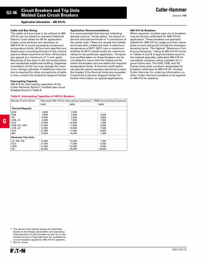
CAT.71.01.T.E
Cutler-HammerJanuary 1999
G2-46
G
Circuit Breakers and Trip UnitsMolded Case Circuit Breakers Application Information – 400-415 Hz
Table K: Interrupting Capacities of 400 Hz Breakers
Breaker Frame Series Estimated 400-415 Hz Interrupting Capacities➀➁ (RMS Symmetrical Amperes)
240V 480V 600V
Thermal Magnetic
EHDFDBFDJDB, JDHJDKDB, KD, HKDLDB, LDHLDMD
3,6003,600
13,0008,000
14,00021,00014,00021,00014,000
2,8002,8005,0007,000
10,00011,00010,00011,00010,000
. . . . .2,8003,6007,0007,0008,0007,0008,0007,000
Electronic Trip Units
LD, MD, NDHLDHNDRD
14,00021,00021,00040,000
10,00011,00016,00033,000
7,0008,0008,000
33,000
➀ The above interrupting ratings are estimates based on the design parameters and operating characteristics of each breaker as well as on the limited amount of test data thus far available for curcuit breakers applied to 400-415 Hz systems.
➁ Not UL listed.
Cable and Bus SizingThe cable and bus sizes to be utilized at 400-415 Hz are not based on standard National Electric Code tables for 60 Hz application. Larger cross sections are necessary at 400-415 Hz to avoid exceeding component temperature limits. All bus bars specified are based upon mounting the bars in the vertical plane to allow maximum air flow. All bus bars are spaced at a minimum of 1⁄4 inch apart. Mounting of bus bars in the horizontal plane will necessitate additional drafting. Edgewise orientation of the bus may change the maxi-mum ratings indicated. If additional informa-tion is required for other connections of cable or bus, contact the Customer Support Center.
Interrupting Capacity400-415 Hz interrupting capacities of the Cutler-Hammer Series C molded case circuit breakers found in Table K.
Application RecommendationsIt is recommended that thermal indicating devices such as “tempi plates” be placed on the line and load terminals or T-connectors of the center pole. These are usually the hottest terminals with a balanced load. A maximum temperature of 90°C (50°C over a maximum ambient of 40°C) would verify the maximum rating for the particular application. Tempera-ture profiles taken on these breakers can be correlated to insure that the hottest points within the breaker care are within the required temperature limits. A thermal cutoff switch can also be used to actuate a shunt trip to open the breaker if the thermal limits are exceeded. Consult the Customer Support Center for further information on special applications.
400-415 Hz BreakersWhen required, molded case circuit breakers may be factory calibrated for 400-415 Hz application. These breakers are specially labeled for 400-415 Hz usage and their name-plate current rating will include the necessary derating factor. The highest “Maximum Con-tinuous Amperes” rating at 400-415 Hz found in Tables A and B is approximately equal to the highest specially calibrated 400-415 Hz nameplate amperes rating available for a given frame size. The EHD, FDB, and FD frames have style numbers designated for breakers calibrated at 400-415 Hz. Contact Cutler-Hammer for ordering information on other Cutler-Hammer breakers to be applied in 400-415 Hz systems.

January 1999
Cutler-Hammer
CAT.71.01.T.E
G2-47
G
Circuit Breakers and Trip UnitsMolded Case Circuit Breakers Application Information – 100% Rated Circuit Breakers
100% Rated Circuit Breakers
The amount of protection designed into a distribution system is often based on economics. However, each project should be furnished with a reliable distribution system that delivers the most effective protection possible for each investment dollar.
Reliable and economic system design can be usually achieved with Westinghouse circuit breakers that are UL listed for application at 100% of their ratings. . .instead of standard breakers that in actual use are applied at 80% of their frame ratings in an enclosure.
The concept between a system design using standard breakers and that using 100% rated breakers is uncomplicated. . .but there are no shortcut methods for determining which de-sign (and devices) is the best choice for a given system. Good engineering practice requires a careful system analysis beginning with the low-est feeder and concluding with the main device.
Also included in the system analysis must be all present and future factors that could affect the size and/or quantity of the breakers and associated hardware, such as switchboard bus, busway, cable, and conduit. Other factors to consider are loads (continuous and noncon-tinuous) and system expansions and trans-formers with provisions for forced air cooling.
A 100% rated breaker receives its UL listing based on tests conducted in a minimum size enclosure with minimum ventilation (if required) and minimum cable sizes, as stated on this nameplate example. All Cutler-Hammer 100% rated breakers have standard electronic trip units.
The NECThe rules and intent of the National Electrical Code governing the use of standard or 100% rated breakers must be understood before recommending or applying such devices.
Section 220-10(b) Continuous and Noncontin-uous Loads of the 1996 National Electrical Code addresses differences between applica-tions of standard rated breakers and 100% rat-ed breakers. (Significant sections are in bold face type.)
Section 220-10(b) covers standard breakers, and the exception 100% rated breakers. NEC Section 220-10(b) and the Section 220-10(b) exception can be expressed by these formulas:
Standard 80% Rated DesignNoncontinuous Load + 125% of the
Continuous Load= Total Minimum Load
Special 100% Rated DesignNoncontinuous Load + Continuous Load
= Total Minimum Load
The necessity for these NEC requirements re-sults from circuit breaker testing procedures.
A molded case circuit breaker is tested in open air to verify its nameplate ampere rating. The nameplate specifies a value of current the circuit breaker is rated to carry continuously without tripping within specific operating temperature guidelines.
In most instances, a breaker is applied in an enclosure and performance could be adversely affected by slow heat dissipation and temperature rise. These factors must be considered regarding the ability of the breaker to comply with its nameplate ampere rating.
Testing Conditions and Operating ConditionsThere are distinct differences between these conditions they are addressed in the NEC Section 220-10(b) by introducing an overcur-rent device and associated hardware sizing factor. The sizing factor ensures reliable equipment performance under realistic conditions. Section 220-10(b) is the key to making the best system design choice.
For feeders, Section 220-20(b) addresses the rating of all overcurrent devices that have been tested in open air but are applied in an enclosure. The thermal response of an over-current device applied in an enclosure will usually be faster than in open air, thus dictating the 125% requirement.
The Exception allows for properly tested and listed overcurrent devices to be applied at 100% of their nameplate rating.
There is a Difference Between100% Rated Breakers and100% Rated Assemblies
Special attention should be given to the word “assembly” in the NEC Exception. Normally, an assembly is listed for 100% operation only after being successfully tested as an assem-bly per UL requirements.
For an assembly to receive a 100% rated UL listing, it must be tested separately by UL project engineers. Panelboards are tested to UL 67, switchboards tested to UL 891.
Installing 100% rated breakers in an assem-bly does not automatically make it acceptable for a 100% rating.
BreakerNameplateExample
100%Application–enclosureandwire ampacityrequirements.
90°C Wire
90°C Wire
The NEC allows the breaker to be rated at 100% of its frame size in an assembly, provided that 90 °C wire is applied at the 75 °C ampacity. All 100% rated circuit breakers have electronic trip units.
“Where a feeder supplies continu-ous loads or any combination of con-tinuous and noncontinuous loads, the rating of the overcurrent device shall not be less than the noncontin-uous load plus 125 percent of the continuous load.”
The minimum circuit conductor size without the application of any ampacity adjustment or correction factors shall have an allowable ampacity equal to or greater than the noncontinuous load plus 125% of the continuous load.
“Exception: Where the assembly including the overcurrent devices protecting the feeder(s) are listed for operation at 100 percent of their rat-ing, neither the ampere rating of the overcurrent device nor the ampacity of the feeder conductors shall be less than the sum of the continuous load plus the noncontinuous load.”

CAT.71.01.T.E
Cutler-HammerJanuary 1999
G2-48
G
Circuit Breakers and Trip UnitsMolded Case Circuit Breakers Application Information – 100% Rated Circuit Breakers
The Application – These examples illustrate the cost savings when the 100% rated approach is utilized*
A visual comparison of breaker, bus, and cable sizes in the Three-Phase Distribution System examples (line diagrams) reveals how a 100% rated system design can provide cost savings.
Feeder #1 Feeder #2 Feeder #3 Main
Three-PhaseDistribution SystemLine Diagrams
ContinuousLoad
400A 800A 0 1200A
NoncontinuousLoad
200A 0 1000A 1200A
Standard 80% Rated Design
Noncontinuous Load + 125% of the Continuous Load = Total Minimum Load
Calculationper NECof MinimumTotal Load➀
200 + (1.25) (400)=700A
0 + (1.25) (800)=1000A 1000 + 0 = 1000A 2700A➀
BreakerFrame (F)Trip (T)Rating
(F) (T)➁800A/700A
(F) (T)➁1200A/1000A
(F) (T)➁1200A/1000A
(F) (T)➁3000A/3000A
Bus/CableRating 800A➁ 1000A 1000A 3000A➁
Standard 100% Rated Design
Noncontinuous Load + Continuous Load = Total Minimum Load
Calculationper NECof MinimumTotal Load➂
200 + 400 = 600A 0 + 800 = 800A 1000 + 0 = 1000A 2400A➃
BreakerFrame (F)Trip (T)Rating
(F) (T)600A/600A
(F) (T)800A/800A
(F) (T)➁1200A/1000A
(F) (T)➁2500A/2500A
Bus/CableRating 600A 800A 1000A 2500A➁
The Result – Savings in Both Switchboard and Cable Costs
StandardDesign
700 AmperesMinimum Total Load
1000 AmperesMinimum Total Load
1000 AmperesMinimum Total Load
2700 AmperesMinimum Total Load
100% Rated BreakerSystems Save Money:Significant economicadvantages – in lower ratedand sized breakers, less cable,and significant reductions inequipment floor and wallspace – can be realized whenthe results of a systemsanalysis favor the 100% rateddesign approach.
100% RatedDesign
600 AmperesMinimum Total Load
800 AmperesMinimum Total Load
1000 AmperesMinimum Total Load
2400 AmperesMinimum Total Load
Results The standard design requires higher rated, more expen-sive breaker and bus. Although the mini-mum total load is 700 amperes, most breakers and hard-ware are available only in standard sizes requiring even more expensive “nearest standard size” breakers and hardware.
Dramatic economic advantages are achieved by using the 100% rated de-sign. Substantial savings result from using an 800 ampere busway and signifi-cant savings are also provided by the smaller breaker frame and cable size.
Calculations indicate either approach re-sults in the same size breaker and hard-ware. A 100% rated breaker would be more expensize al-though the final deci-sion could rest on whether or not future load growth is antici-pated.
The 100% approach provides significant economic advantag-es. It not only per-mits use of the smaller size 2500 ampere breaker (nearest standard size) and main bus. Westinghouse offers a 2500 ampere frame breaker which fur-ther enhances the economic value of the 100% rated de-sign.
➀ (Noncontinuous Load) + (125%) (Continuous Load) per NEC Section 220-10(b).
➁ Nearest standard size, not less than calculated value.
➂ (Noncontinuous Load) + (Continuous Load) per NEC Section 220-10(b) Exception.
➃ Sum of all NEC calculated minimum feeder loads.
* Selection of either a 100% rated design or stan-dard design must result from a system analysis beginning with the lowest feeder and concluding with the system’s main device. For these system examples, assume that all assembly testing has been successfully completed and either the 100% rated design or standard design can be selected.
Each system is hypothetical and either approach will meet safety requirements. Loads were arbi-trarily selected. The load table includes the calcu-lations for minimum total loads in conformance with NEC Section 22-10(b).
3000A F3000A T
800A F700A T
1200A F1000A T
1200A F1000A T
3000A Bus
Swbd. 1000A BusMCC 800A Bus
3-400 kcmil,Cu per ø
2-500 kcmil,Cu per ø
3-400 kcmil,Cu per ø
1000A Busway
Feeder#1
Feeder#2
Feeder#3
2500A F2500A T
600A F600A T
800A F800A T
1200A F1000A T
2500A Bus
Swbd. 1000A BusMCC 600A Bus
3-400 kcmil,Cu per ø
2-350 kcmil,Cu per ø
2-600 kcmil,Cu per ø
800A Busway
Feeder#1
Feeder#2
Feeder#3
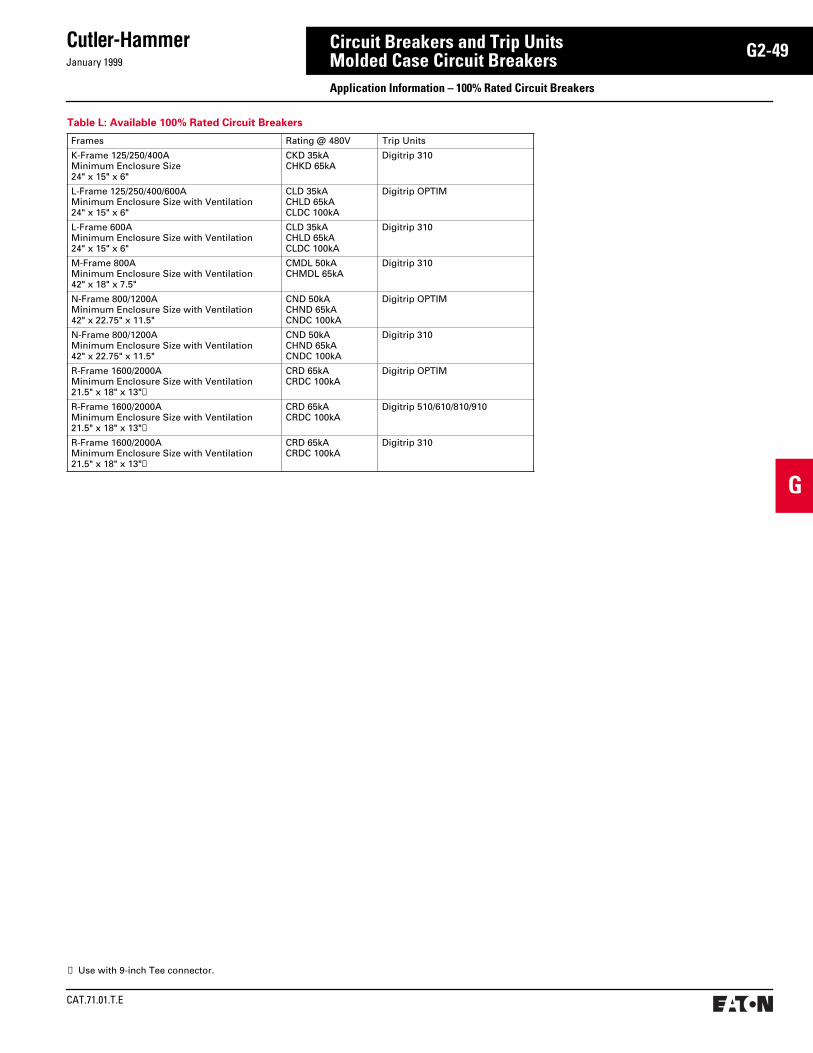
January 1999
Cutler-Hammer
CAT.71.01.T.E
G2-49
G
Circuit Breakers and Trip UnitsMolded Case Circuit Breakers Application Information – 100% Rated Circuit Breakers
Table L: Available 100% Rated Circuit Breakers
Frames Rating @ 480V Trip Units
K-Frame 125/250/400AMinimum Enclosure Size24" x 15" x 6"
CKD 35kACHKD 65kA
Digitrip 310
L-Frame 125/250/400/600AMinimum Enclosure Size with Ventilation24" x 15" x 6"
CLD 35kACHLD 65kACLDC 100kA
Digitrip OPTIM
L-Frame 600AMinimum Enclosure Size with Ventilation24" x 15" x 6"
CLD 35kACHLD 65kACLDC 100kA
Digitrip 310
M-Frame 800AMinimum Enclosure Size with Ventilation42" x 18" x 7.5"
CMDL 50kACHMDL 65kA
Digitrip 310
N-Frame 800/1200AMinimum Enclosure Size with Ventilation42" x 22.75" x 11.5"
CND 50kACHND 65kACNDC 100kA
Digitrip OPTIM
N-Frame 800/1200AMinimum Enclosure Size with Ventilation42" x 22.75" x 11.5"
CND 50kACHND 65kACNDC 100kA
Digitrip 310
R-Frame 1600/2000AMinimum Enclosure Size with Ventilation21.5" x 18" x 13"➀
CRD 65kACRDC 100kA
Digitrip OPTIM
R-Frame 1600/2000AMinimum Enclosure Size with Ventilation21.5" x 18" x 13"➀
CRD 65kACRDC 100kA
Digitrip 510/610/810/910
R-Frame 1600/2000AMinimum Enclosure Size with Ventilation21.5" x 18" x 13"➀
CRD 65kACRDC 100kA
Digitrip 310
➀ Use with 9-inch Tee connector.

CAT.71.01.T.E
Cutler-HammerJanuary 1999
G2-50
G
Circuit Breakers and Trip UnitsMolded Case Circuit Breakers Application Information – Series Rated System
Series Rated Systems
Under most circumstances, selection of a series rated system will reduce initial cost and size, since downstream breakers are not fully-rated for the prospective short-circuit fault cur-rent at their point of application. The interrupt-ing rating of the upstream breaker must always be equal to or greater than the available fault current at its line terminals. In addition, down-stream breakers must have been tested in combination with the upstream breaker and shown to be protected by the upstream break-er at the assigned series rated interrupting rating. The net result is that the system can be assigned a “series rated” or “integrated” rating higher than the rating of the down-stream breaker when it is tested or applied alone. Design of the system and selection of breakers is based on short-circuit interruption test specified and witnessed by UL.
Because of their blow-open design, most molded case circuit breakers are current limiting to some degree. In a series rated application and in the event of a major fault, both upstream and downstream breakers open, protecting the lower-rated downstream devices by limiting the let-through current.
To develop a series rated protective system, it is suggested that the design engineer, after completing preliminary steps:● Define available fault current at the line
side terminals of the upstream breaker.● Select an upstream breaker with an inter-
rupting rating equal to or greater than the available fault current.
● Verify the series tested interrupting ratings of the selected combination of breakers by referring to the tables in the back of this brochure.
● Confirm, during installation, that the correct breakers have been selected by checking the nameplates appearing on the end-use equipment.
Evaluating the Protection SystemsDesigned properly, all three systems protect electrical equipment with equal effectiveness. But initial cost and continuity of service can vary widely depending on the inherent characteristics of the system, and on the design philosophy adopted.
Fully-rated SystemA fully-rated system is typically less costly than a selectively-coordinated system and more costly than a series rated system. All breakers are rated for full fault current at their point of application in accordance with the National Electrical Code. The continuity of service provided by the system is less than with a selectively-coordinated system, and can be more than a series rated system.
Selectively-coordinated SystemA selectively-coordinated system is most costly of the three. All breakers are fully-rated
and upstream breakers must have adequate short-time delay adjusting capabilities. Continuity of service is the highest possible.
Series Rated SystemA series rated system is least costly. The up-stream breaker is always fully-rated, but the interrupting ratings of downstream breakers are normally lower. Service continuity can be acceptable after initial start-up, since the low-er-level arcing faults most likely to occur after that time can be cleared by the downstream breaker alone. However, under high fault conditions, both the upstream and down-stream breakers would open, eliminating service to the affected portion of the system.
National Electrical Code Requirements Requirements of the National Electrical Code for short-circuit ratings may now be met by equipment that is marked with ratings adequate for the available fault current at their point of application in the electrical system. Refer to the current NEC for specific requirements.
General DiscussionAvailable Short-circuit Current. Service equipment shall be suitable for the short-circuit current available at its supply terminal.
Approval. The conductors and equipment required or permitted by the Code shall be acceptable only if approved. See Examination of Equipment for Safety and Examination, Identification, Installation, and Use of Equipment. See definitions of “Approved”, “Identified”, “Labeled” and “Listed”.
Examination, Identification, Installation and Use of Equipment
A. Examination: In judging equipment, con-siderations such as the following should be evaluated.
1. Suitability for installation and use in conformity with the provisions of this Code. Suitability of equipment use may be identified by a description marked on or provided with a product to identify the suitability of the product for a specific purpose, environment, or application. Suitability of equipment may be evidence by listing or labeling.
2. Mechanical strength and durability, including, for parts designed to enclose and protect other equipment, the adequacy of the protection thus provided.
3. Wire-ending and connection space.4. Electrical insulation.5. Heating effects under normal conditions
of use and also under abnormal conditions likely to arise in service.
6. Arcing effects.7. Classification by type, size, voltage,
current capacity and specific use.8. Other factors which contribute to the
practical safeguarding of persons using or likely to come in contact with the equipment.
B. Installation and Use: Listed or labeled equipment shall be used or installed in accordance with any instructions included in the listing or labeling.
Interrupting Rating. Equipment intended to break current at fault levels shall have an interrupting rating sufficient for the system voltage and the current which is available at the terminals of the equipment. Equipment intended to break current at other than fault levels shall have an interrupting rating at system voltage sufficient for the current that must be interrupted.
Circuit Impedance and Other Characteristics The overcurrent protective devices, the total impedance, the component short-circuit withstanding ratings, and other characteris-tics of the circuit to be protected shall be so selected and coordinated as to permit the circuit protective devices used to clear a fault without the occurrence of extensive damage to the electrical components of the circuit. This fault shall be assumed to be either two or more of the circuit conductors, or between any circuit conductor and the grounding conductor or enclosing metal raceway.
Design/Test Considerations for Series Coordinated Circuit BreakersTest Procedures for all Cutler-Hammer Series C and other molded case circuit breakers intended for application in series connected systems are in full compliance with all appli-cable paragraphs of the latest edition of UL 489➀. The entire system is tested, since such tests are the only way to correctly verify the performance of overcurrent devices under short-circuit conditions.
Calibration, interruption, trip-out, and dielec-tric withstand tests are performed. Breakers in their as-received condition are used for the interrupting and intermediate interrupting capability tests. If agreeable to concerned par-ties, previously tested samples may be used. The interrupting rating of the line-side circuit breaker is equal to or greater than the maxi-mum available fault current on the distribution system at its point of intended application.
Tests comply also with the intent of the proposed revisions to applicable IEC documents.➀
Tests are completed in a well-defined sequence:● Interrupting Tests● Intermediate Interrupting Tests● Trip-out Tests● Dielectric Voltage-withstand Tests
Cutler-Hammer Series C Circuit Breakers intended for application in series rated systems are subjected, in the following sequence, to interrupting ability, intermedi-ate interrupting ability, trip-out, and dielectric voltage-withstand tests.
➀ For further information, see IEEE Standards 141, 242 and 446.
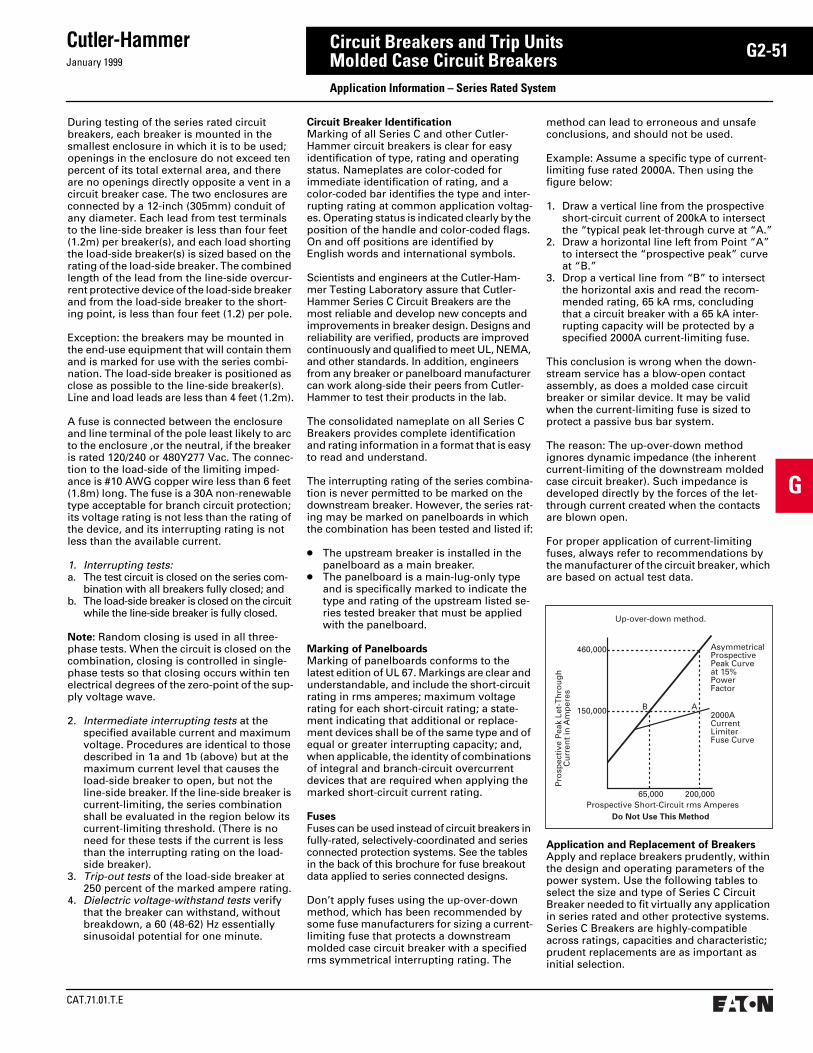
January 1999
Cutler-Hammer
CAT.71.01.T.E
G2-51
G
Circuit Breakers and Trip UnitsMolded Case Circuit Breakers Application Information – Series Rated System
During testing of the series rated circuit breakers, each breaker is mounted in the smallest enclosure in which it is to be used; openings in the enclosure do not exceed ten percent of its total external area, and there are no openings directly opposite a vent in a circuit breaker case. The two enclosures are connected by a 12-inch (305mm) conduit of any diameter. Each lead from test terminals to the line-side breaker is less than four feet (1.2m) per breaker(s), and each load shorting the load-side breaker(s) is sized based on the rating of the load-side breaker. The combined length of the lead from the line-side overcur-rent protective device of the load-side breaker and from the load-side breaker to the short-ing point, is less than four feet (1.2) per pole.
Exception: the breakers may be mounted in the end-use equipment that will contain them and is marked for use with the series combi-nation. The load-side breaker is positioned as close as possible to the line-side breaker(s). Line and load leads are less than 4 feet (1.2m).
A fuse is connected between the enclosure and line terminal of the pole least likely to arc to the enclosure ,or the neutral, if the breaker is rated 120/240 or 480Y277 Vac. The connec-tion to the load-side of the limiting imped-ance is #10 AWG copper wire less than 6 feet (1.8m) long. The fuse is a 30A non-renewable type acceptable for branch circuit protection; its voltage rating is not less than the rating of the device, and its interrupting rating is not less than the available current.
1. Interrupting tests:a. The test circuit is closed on the series com-
bination with all breakers fully closed; andb. The load-side breaker is closed on the circuit
while the line-side breaker is fully closed.
Note: Random closing is used in all three-phase tests. When the circuit is closed on the combination, closing is controlled in single-phase tests so that closing occurs within ten electrical degrees of the zero-point of the sup-ply voltage wave.
2. Intermediate interrupting tests at the specified available current and maximum voltage. Procedures are identical to those described in 1a and 1b (above) but at the maximum current level that causes the load-side breaker to open, but not the line-side breaker. If the line-side breaker is current-limiting, the series combination shall be evaluated in the region below its current-limiting threshold. (There is no need for these tests if the current is less than the interrupting rating on the load-side breaker).
3. Trip-out tests of the load-side breaker at 250 percent of the marked ampere rating.
4. Dielectric voltage-withstand tests verify that the breaker can withstand, without breakdown, a 60 (48-62) Hz essentially sinusoidal potential for one minute.
Circuit Breaker IdentificationMarking of all Series C and other Cutler-Hammer circuit breakers is clear for easy identification of type, rating and operating status. Nameplates are color-coded for immediate identification of rating, and a color-coded bar identifies the type and inter-rupting rating at common application voltag-es. Operating status is indicated clearly by the position of the handle and color-coded flags. On and off positions are identified by English words and international symbols.
Scientists and engineers at the Cutler-Ham-mer Testing Laboratory assure that Cutler-Hammer Series C Circuit Breakers are the most reliable and develop new concepts and improvements in breaker design. Designs and reliability are verified, products are improved continuously and qualified to meet UL, NEMA, and other standards. In addition, engineers from any breaker or panelboard manufacturer can work along-side their peers from Cutler-Hammer to test their products in the lab.
The consolidated nameplate on all Series C Breakers provides complete identification and rating information in a format that is easy to read and understand.
The interrupting rating of the series combina-tion is never permitted to be marked on the downstream breaker. However, the series rat-ing may be marked on panelboards in which the combination has been tested and listed if:
● The upstream breaker is installed in the panelboard as a main breaker.
● The panelboard is a main-lug-only type and is specifically marked to indicate the type and rating of the upstream listed se-ries tested breaker that must be applied with the panelboard.
Marking of PanelboardsMarking of panelboards conforms to the latest edition of UL 67. Markings are clear and understandable, and include the short-circuit rating in rms amperes; maximum voltage rating for each short-circuit rating; a state-ment indicating that additional or replace-ment devices shall be of the same type and of equal or greater interrupting capacity; and, when applicable, the identity of combinations of integral and branch-circuit overcurrent devices that are required when applying the marked short-circuit current rating.
FusesFuses can be used instead of circuit breakers in fully-rated, selectively-coordinated and series connected protection systems. See the tables in the back of this brochure for fuse breakout data applied to series connected designs.
Don’t apply fuses using the up-over-down method, which has been recommended by some fuse manufacturers for sizing a current-limiting fuse that protects a downstream molded case circuit breaker with a specified rms symmetrical interrupting rating. The
method can lead to erroneous and unsafe conclusions, and should not be used.
Example: Assume a specific type of current-limiting fuse rated 2000A. Then using the figure below:
1. Draw a vertical line from the prospective short-circuit current of 200kA to intersect the “typical peak let-through curve at “A.”
2. Draw a horizontal line left from Point “A” to intersect the “prospective peak” curve at “B.”
3. Drop a vertical line from “B” to intersect the horizontal axis and read the recom-mended rating, 65 kA rms, concluding that a circuit breaker with a 65 kA inter-rupting capacity will be protected by a specified 2000A current-limiting fuse.
This conclusion is wrong when the down-stream service has a blow-open contact assembly, as does a molded case circuit breaker or similar device. It may be valid when the current-limiting fuse is sized to protect a passive bus bar system.
The reason: The up-over-down method ignores dynamic impedance (the inherent current-limiting of the downstream molded case circuit breaker). Such impedance is developed directly by the forces of the let-through current created when the contacts are blown open.
For proper application of current-limiting fuses, always refer to recommendations by the manufacturer of the circuit breaker, which are based on actual test data.
Application and Replacement of BreakersApply and replace breakers prudently, within the design and operating parameters of the power system. Use the following tables to select the size and type of Series C Circuit Breaker needed to fit virtually any application in series rated and other protective systems. Series C Breakers are highly-compatible across ratings, capacities and characteristic; prudent replacements are as important as initial selection.
65,000 200,000
150,000
460,000
B A
AsymmetricalProspectivePeak Curveat 15%PowerFactor
2000ACurrentLimiterFuse Curve
Prospective Short-Circuit rms Amperes
Pro
spec
tive
Pea
k Le
t-T
hro
ug
hC
urr
ent
in A
mp
eres
Do Not Use This Method
Up-over-down method.

CAT.71.01.T.E
Cutler-HammerJanuary 1999
G2-52
G
Circuit Breakers and Trip UnitsMolded Case Circuit Breakers Series C Breakers for Series Connected Protection of Power Distribution Systems
Circuit Breaker/Circuit Breaker Series Combinations➀➁ 600 Volt System
Upstream Breaker Type FD, FDB,HFD
FD, FDB,HFD
LCL LCL KDC KDC HLD, HLDB HKD JDC
Amperes, Maximum
150 70 400 250 400 400 600 400 250
Limiter Type
LFD3150R LFD3070R . . . . . . . . . . . . . . . . . . . . . . . . . . . .
System kA 200 200 100 100 50 42 35 35 35
System Volts 600 600 600 600 600 600 600 600 600
DownstreamBreaker
Range Amps
Poles
FDB 15-70 2, 3 ■ ■ ■ ■ ■ ■
FD 15-70 2, 3 ■ ■ ■ ■ ■ ■
HFD 15-70 2, 3 ■ ■ ■ ■ ■ ■
FDC 15-70 2, 3 ■ ■ ■
FDB 80-150 2, 3 ■ ■ ■ ■ ■ ■
FD 80-150 2, 3 ■ ■ ■ ■ ■ ■
HFD 80-150 2, 3 ■ ■ ■ ■ ■ ■
FDC 80-150 2, 3 ■ ■ ■
JD 70-250 2, 3 ■ ■ ■ ■ ■
JDB 70-250 2, 3 ■ ■ ■ ■ ■
HJD 70-250 2, 3 ■ ■ ■ ■ ■
JDC 70-250 2, 3 ■
KD 100-400 2, 3 ■ ■ ■
KDB 100-400 2, 3 ■ ■ ■
HKD 100-400 2, 3 ■ ■
KDC 100-400 2, 3 ■
LD, LDB 300-600 2, 3 ■
LC, LCG,LCA,LCGA
75-400 2, 3 ■ ■ ■
HLC, HLCG, HLCA, HLCGA
75-400 2, 3 ■ ■ ■
➀ Circuit Breaker/Circuit Breaker series rated combinations shown in above tabulations by Underwriters Laboratories, Inc. in their Component Directory (Yellow Book) under “Circuit Breakers — Series Connected.”
➁ Only active Circuit Breaker types are included in the above tabulations. For additional information on inactive styles, consult the UL Yellow Book or contact Cutler-Hammer.
The series combinations shown are UL recognized component rating only. Consult the equip-ment manufacturer for applica-ble UL recognized assembly combinations.
■ A solid block in the row of a particular down-stream breaker indicates that the upstream de-vice associated with the column provides a Series Rating for the parameter values of the column heading. If the solid block is accompanied by numbers in parentheses, then only the breaker ampacities listed in the parentheses have the Series Rating.
Index for Series Rating Tables
System Voltage Pages
Circuit Breaker/Circuit Breaker
600 Volt480 Volt480Y/277 Volt240 Volt120/240 Volt
G2-52, G2-53G2-54, G2-55G2-56, G2-57G2-58, G2-59G2-60, G2-61
Fuse/Circuit Breaker
600, 480, 480/277240, 120/240 Volt G2-62, G2-63

January 1999
Cutler-Hammer
CAT.71.01.T.E
G2-53
G
Circuit Breakers and Trip UnitsMolded Case Circuit Breakers Series C Breakers for Series Connected Protection of Power Distribution Systems
Series Connected Ratings: Series C and Other Cutler-Hammer Circuit Breakers
A wide range of breakers and combinations in the Cutler-Hammer Series C and other lines is available that has been tested in accordance with UL procedures for series connected ratings: individually enclosed breakers in
series with main lug panelboards, main breakers integral with branch breakers in panelboards, in switchboards, and in meter centers. You can rely on the enclosed data for applications with other undefined distribution equipment where series application ratings can be an advantage.
Circuit Breaker/Circuit Breaker Series Combinations➀➁ 600 Volt System
FDC FDC HLD,HLDB
KD, KDB HJD HFD HFD JD, JDB FD FD Type
225 150 600 400 250 225 150 250 225 150 Amperes,Maximum
. . . . . . . . . . . . . . . . . . . . . . . . . . . . . . . . . . . . . . . . LimiterType
35 35 25 25 25 25 25 18 18 18 System kA
600 600 600 600 600 600 600 600 600 600 System Volts
■ ■ ■ ■ ■ ■ ■ ■ ■ FDB
■ ■ ■ ■ ■ ■ ■ ■ ■ FD
■ HFD
FDC
■ ■ ■ ■ ■ ■ ■ ■ ■ FDB
■ ■ ■ ■ ■ ■ ■ ■ FD
■ HFD
FDC
■ ■ ■ JD
■ ■ ■ JDB
HJD
JDC
KD
KDB
HKD
KDC
LD, LDB
■ LC, LCG, LCA,LCGA
HLC, HLCG, HLCA,HLCGA
➀ Circuit Breaker/Circuit Breaker series rated combinations shown in above tabulations by Underwriters Laboratories, Inc. in their Component Directory (Yellow Book) under “Circuit Breakers — Series Connected.”
➁ Only active Circuit Breaker types are included in the above tabulations. For additional information on inactive styles, consult the UL Yellow Book or contact Cutler-Hammer.
■ A solid block in the row of a particular down-stream breaker indicates that the upstream device associated with the column provides a Series Rating for the parameter values of the column heading. If the solid block is accompa-nied by numbers in parentheses, then only the breaker ampacities listed in the parentheses have the Series Rating.

CAT.71.01.T.E
Cutler-HammerJanuary 1999
G2-54
G
Circuit Breakers and Trip UnitsMolded Case Circuit Breakers Series C Breakers for Series Connected Protection of Power Distribution Systems
The series combinations shown are UL recognized component rating only. Consult the equip-ment manufacturer for applica-ble UL recognized assembly combinations.
Circuit Breaker/Circuit Breaker Series Combinations➀➁ 480 Volt System
Upstream Breaker Type FDB, FD,HFD
FDB, FD,HFD
LCL LCL FCL NBTRI-PAC
NBTRI-PAC
KDC JDC LATRI-PAC
Amperes,Maximum
150 70 400 250 100 800 500 400 250 400
LimiterType
LFD3150R LFD3070R . . . . . . . . . . . . P20 P12 . . . . . . . . P10
System kA 200 200 150 150 150 100 100 100 100 100
System Volts 480 480 480 480 480 480 480 480 480 480
DownstreamBreaker
RangeAmperes
Poles
EHD 15-100 2, 3 ■(80-100)
■(15-70)
■ ■ ■ ■ ■
FDB 15-150 2, 3 ■(80-150)
■(15-70)
■ ■ ■(15-100)
■ ■
FD 15-150 2, 3 ■(80-150)
■(15-70)
■ ■ ■(15-100)
■ ■
HFD 15-150 2, 3 ■(80-150)
■(15-70)
■ ■ ■(15-100)
■ ■
FDC 15-150 2, 3 ■(80-150)
■(15-70)
■ ■
JD, JDB 70-250 2, 3 ■ ■ ■ ■ ■ ■
HJD 70-250 2, 3 ■ ■ ■ ■ ■ ■
KD, KDB 100-400 2, 3 ■ ■ ■ ■
HKD 100-400 2, 3 ■ ■ ■ ■
LD, LDB 300-600 2, 3
LC, LCG, LCA, LCGA
75-600 2, 3 ■(75-400)
■ ■(75-500)
■(75-400)
HLC, HLCG, HLCA, HLCGA
75-600 2, 3 ■(75-400)
■(75-400)
LA, LAB, HLA 125-600 2, 3 ■ ■(125-500)
MA 125-800 2, 3 ■ ■(125-500)
MC, MCA, MCG, MCGA
400-800 2, 3 ■ ■(400-500)
NB 700-800 2, 3 ■ ■
➀ Circuit Breaker/Circuit Breaker series rated combinations shown in above tabulations by Underwriters Laboratories, Inc. in their Component Directory (Yellow Book) under “Circuit Breakers — Series Connected.”
➁ Only active Circuit Breaker types are included in the above tabulations. For additional information on inactive styles, consult the UL Yellow Book or contact Cutler-Hammer.
■ A solid block in the row of a particular down-stream breaker indicates that the upstream device associated with the column provides a Series Rating for the parameter values of the column heading. If the solid block is accompa-nied by numbers in parentheses, then only the breaker ampacities listed in the parentheses have the Series Rating.

January 1999
Cutler-Hammer
CAT.71.01.T.E
G2-55
G
Circuit Breakers and Trip UnitsMolded Case Circuit Breakers Series C Breakers for Series Connected Protection of Power Distribution Systems
Circuit Breaker/Circuit Breaker Series Combinations➀➁ 480 Volt System
LATRI-PAC
FDC FDC FBTRI-PAC
HLD,HLDB
HKD HJD HFD HFD KD, KDB
JD, JDB
FD FD Type
200 225 150 100 600 400 250 225 150 400 250 225 150 Amperes,Maximum
P08 . . . . . . . . P06 . . . . . . . . . . . . . . . . . . . . . . . . . . . . . . . . . . . . LimiterType
100 100 100 100 65 65 65 65 65 35 25 25 25 System kA
480 480 480 480 480 480 480 480 480 480 480 480 480 System Volts
■ ■ ■ ■ ■ ■ ■ ■ ■ ■ ■ ■ EHD
■(15-100)
■ ■ ■(15-100)
■ ■ ■ ■ ■ ■ ■ ■ FDB
■(15-100)
■ ■(15-100)
■ ■ ■ ■ FD
■(15-100)
■ ■(15-100)
HFD
FDC
■(70-200)
■ ■ JD, JDB
■(70-200)
HJD
■ KD, KDB
HKD
■ LD, LDB
■(75-400)
■(75-400)
LC, LCG, LCA, LCGA
HLC, HLCG,HLCA, HLCGA
■(125-400)
LA, LAB, HLA
MA
MC, MCA, MCG, MCGA
NB
➀ Circuit Breaker/Circuit Breaker series rated combinations shown in above tabulations by Underwriters Laboratories, Inc. in their Component Directory (Yellow Book) under “Circuit Breakers — Series Connected.”
➁ Only active Circuit Breaker types are included in the above tabulations. For additional information on inactive styles, consult the UL Yellow Book or contact Cutler-Hammer.
■ A solid block in the row of a particular down-stream breaker indicates that the upstream device associated with the column provides a Series Rating for the parameter values of the column heading. If the solid block is accompa-nied by numbers in parentheses, then only the breaker ampacities listed in the parentheses have the Series Rating.

CAT.71.01.T.E
Cutler-HammerJanuary 1999
G2-56
G
Circuit Breakers and Trip UnitsMolded Case Circuit Breakers Series C Breakers for Series Connected Protection of Power Distribution Systems
The series combinations shown are UL recognized component rating only. Consult the equip-ment manufacturer for applica-ble UL recognized assembly combinations.
Circuit Breaker/Circuit Breaker Series Combinations➀➁ 480Y/277 Volt System
Upstream Breaker
Type FD, FDB, HFD
FD, FDB, HFD
LCL LCL FCL KDC JDC FDC FDC LATRI-PAC
Amperes, Maximum
150 70 400 250 100 400 250 225 150 200
Limiter Type
LFD3150R LFD3070R . . . . . . . . . . . . . . . . . . . . . . . . . . . . P08
System kA
200 200 150 150 150 100 100 100 100 100
System Volts
480Y/277 480Y/277 480Y/277 480Y/277 480Y/277 480Y/277 480Y/277 480Y/277 480Y/277 480Y/277
Down-streamBreaker
Range Amps
Poles
EHD 15-100 1 ■ ■ ■ ■ ■ ■ ■
EHD 15-100 2, 3 ■(80-100)
■(15-70)
■ ■ ■ ■ ■ ■ ■
FDB 15-150 2, 3 ■(80-150)
■(15-70)
■ ■ ■ ■ ■ ■ ■(15-100)
FD 15-150 1 ■ ■ ■ ■ ■ ■ ■(15-100)
FD 15-150 2, 3 ■(80-150)
■(15-70)
■ ■ ■ ■ ■ ■ ■(15-100)
HFD 15-150 1 ■ ■ ■ ■ ■ ■ ■(15-100)
HFD 15-150 2, 3 ■(80-150)
■(15-70)
■ ■ ■ ■ ■ ■ ■(15-100)
GHB, GHC 15-100 1 ■ ■ ■ ■ ■ ■ ■
GHB, GHC 15-100 2, 3 ■(80-100)
■(15-70)
■ ■ ■ ■(15-50)
■(15-50)
■ ■
➀ Circuit Breaker/Circuit Breaker series rated combinations shown in above tabulations by Underwriters Laboratories, Inc. in their Component Directory (Yellow Book) under “Circuit Breakers — Series Connected.”
➁ Only active Circuit Breaker types are included in the above tabulations. For additional information on inactive styles, consult the UL Yellow Book or contact Cutler-Hammer.
■ A solid block in the row of a particular down-stream breaker indicates that the upstream device associated with the column provides a Series Rating for the parameter values of the column heading. If the solid block is accompa-nied by numbers in parentheses, then only the breaker ampacities listed in the parentheses have the Series Rating.
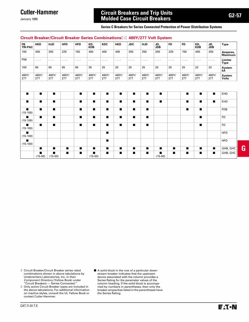
January 1999
Cutler-Hammer
CAT.71.01.T.E
G2-57
G
Circuit Breakers and Trip UnitsMolded Case Circuit Breakers Series C Breakers for Series Connected Protection of Power Distribution Systems
Circuit Breaker/Circuit Breaker Series Combinations➀➁ 480Y/277 Volt System
FBTRI-PAC
HKD HJD HFD HFD KD, KDB
KDC HKD JDC HJD JD, JDB
FD FD KD, KDB
JD, JDB
Type
100 400 250 225 150 400 400 400 250 250 250 225 150 400 250 Amperes,Maximum
P06 . . . . . . . . . . . . . . . . . . . . . . . . . . . . . . . . . . . . . . . . . . . . . . . . . . . . . . . . LimiterType
100 65 65 65 65 35 25 25 25 25 25 25 25 22 22 System kA
480Y/277
480Y/277
480Y/277
480Y/277
480Y/277
480Y/277
480Y/277
480Y/277
480Y/277
480Y/277
480Y/277
480Y/277
480Y/277
480Y/277
480Y/277
SystemVolts
■ ■ ■ ■ ■ ■ ■ ■ ■ ■ ■ ■ ■ EHD
■ ■ ■ ■ ■ ■ ■ ■ ■ ■ ■ ■ ■ EHD
■(15-100)
■ ■ ■ ■ ■ ■ ■ ■ ■ ■ FDB
■(15-100)
■ ■ ■ ■ ■ ■ ■ ■ ■ FD
■(15-100)
■ ■ ■ ■ ■ ■ ■ ■ ■ FD
■(15-100)
■ HFD
■(15-100)
■ HFD
■ ■ ■ ■ ■ ■ ■ ■ ■ ■ ■ ■ ■ ■ GHB, GHC
■(15-50)
■(15-50)
■ ■ ■(15-50)
■ ■ ■ ■ ■(15-50)
■ ■ ■ ■ GHB, GHC
➀ Circuit Breaker/Circuit Breaker series rated combinations shown in above tabulations by Underwriters Laboratories, Inc. in their Component Directory (Yellow Book) under “Circuit Breakers — Series Connected.”
➁ Only active Circuit Breaker types are included in the above tabulations. For additional information on inactive styles, consult the UL Yellow Book or contact Cutler-Hammer.
■ A solid block in the row of a particular down-stream breaker indicates that the upstream device associated with the column provides a Series Rating for the parameter values of the column heading. If the solid block is accompa-nied by numbers in parentheses, then only the breaker ampacities listed in the parentheses have the Series Rating.

CAT.71.01.T.E
Cutler-HammerJanuary 1999
G2-58
G
Circuit Breakers and Trip UnitsMolded Case Circuit Breakers Series C Breakers for Series Connected Protection of Power Distribution Systems
The series combinations shown are UL recognized component rating only. Consult the equip-ment manufacturer for applica-ble UL recognized assembly combinations.
Circuit Breaker/Circuit Breaker Series Combinations➀➁ 240 Volt System
Upstream Breaker
Type LCL KDC LCL JDC FDC FCL FD, FDB, HFD
FD, FDB, HFD
HLD,HLDB
NBTRI-PAC
NBTRI-PAC
LATRI-PAC
FBTRI-PAC
KDC HKD JDC HJD EDH
Amperes, Maximum
400 400 250 250 150 100 150 70 600 800 500 200 100 400 400 250 250 225
Limiter Type
. . . . . . . . . . . . . . . . . . . . . . . . LFD3150R
LFD3070R
. . . . P20 P12 P08 P06 . . . . . . . . . . . . . . . . . . . .
System kA 200 200 200 200 200 200 200 200 100 100 100 100 100 100 100 100 100 100
System Volts 240 240 240 240 240 240 240 240 240 240 240 240 240 240 240 240 240 240
DownstreamBreaker
Range Amperes
Poles
BA, BR, HQP, QC
15-100 2, 3 ■ ■ ■ ■(80-100)
■(15-70)
■ ■ ■ ■
QBHW, BRH, QPHW, QCHW
15-100 2, 3 ■ ■ ■ ■(80-100)
■(15-70)
■ ■ ■ ■ ■
HBAX, QHPX, QHCX
15-100 3 ■ ■ ■ ■(80-100)
■(15-70)
■ ■ ■ ■
HBAW, QH-PW, QHCW
15-20 3 ■ ■ ■ ■ ■ ■ ■
GB, GHB 15-100 2, 3 ■ ■ ■ ■ ■ ■ ■(80-100)
■(15-70)
■ ■ ■ ■ ■
GC, GHC 15-100 2, 3 ■ ■ ■ ■ ■ ■ ■(80-100)
■(15-70)
■ ■ ■ ■ ■
CA, CAH, HCA 100-225 2, 3 ■ ■ ■ ■ ■ ■ ■ ■ ■
BJ, BJH 100-225 2, 3 ■ ■ ■ ■ ■ ■
ED 100-225 2, 3 ■ ■ ■ ■ ■ ■ ■ ■
EDH 100-225 2, 3 ■ ■ ■ ■
EHD 15-100 2, 3 ■ ■ ■ ■ ■ ■ ■(80-100)
■(15-70)
■ ■ ■ ■ ■ ■
FD, FDB 15-150 2, 3 ■ ■ ■ ■ ■ ■(15-100)
■(80-150)
■(15-70)
■ ■(15-100)
■(15-100)
■ ■ ■ ■
HFD 15-150 2, 3 ■ ■ ■ ■ ■ ■(15-100)
■(80-150)
■(15-70)
■ ■
JD, JDB 70-250 2, 3 ■ ■ ■ ■ ■ ■ ■ ■ ■ ■ ■
HJD 70-250 2, 3 ■ ■ ■ ■ ■ ■
DK 250-400 2, 3 ■ ■ ■ ■ ■ ■ ■
KD, KDB 100-400 2, 3 ■ ■ ■ ■ ■ ■ ■
HKD 100-400 2, 3 ■ ■ ■
LD, LDB 300-600 2, 3 ■
HLD 300-600 2, 3
LC, LCG, LCA, LCGA
75-400 2, 3 ■ ■ ■ ■
HLC, HLCG, HLCA, HLCGA
75-400 2, 3 ■ ■ ■ ■
➀ Circuit Breaker/Circuit Breaker series rated combinations shown in above tabulations by Underwriters Laboratories, Inc. in their Component Directory (Yellow Book) under “Circuit Breakers — Series Connected.”
➁ Only active Circuit Breaker types are included in the above tabulations. For additional information on inactive styles, consult the UL Yellow Book or contact Cutler-Hammer.
■ A solid block in the row of a particular down-stream breaker indicates that the upstream device associated with the column provides a Series Rating for the parameter values of the column heading. If the solid block is accompa-nied by numbers in parentheses, then only the breaker ampacities listed in the parentheses have the Series Rating.
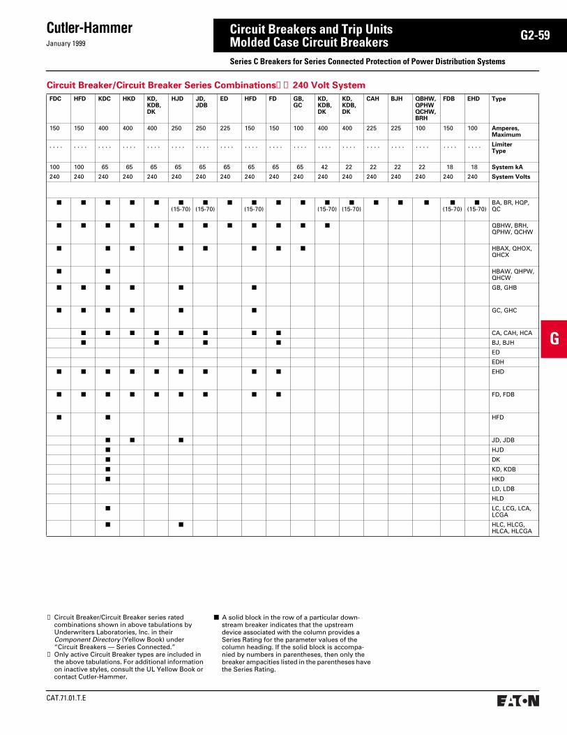
January 1999
Cutler-Hammer
CAT.71.01.T.E
G2-59
G
Circuit Breakers and Trip UnitsMolded Case Circuit Breakers Series C Breakers for Series Connected Protection of Power Distribution Systems
Circuit Breaker/Circuit Breaker Series Combinations➀➁ 240 Volt System
FDC HFD KDC HKD KD, KDB, DK
HJD JD, JDB
ED HFD FD GB, GC
KD, KDB, DK
KD, KDB, DK
CAH BJH QBHW, QPHW QCHW, BRH
FDB EHD Type
150 150 400 400 400 250 250 225 150 150 100 400 400 225 225 100 150 100 Amperes, Maximum
. . . . . . . . . . . . . . . . . . . . . . . . . . . . . . . . . . . . . . . . . . . . . . . . . . . . . . . . . . . . . . . . . . . . . . . . Limiter Type
100 100 65 65 65 65 65 65 65 65 65 42 22 22 22 22 18 18 System kA
240 240 240 240 240 240 240 240 240 240 240 240 240 240 240 240 240 240 System Volts
■ ■ ■ ■ ■ ■(15-70)
■(15-70)
■ ■(15-70)
■ ■ ■(15-70)
■(15-70)
■ ■ ■ ■(15-70)
■(15-70)
BA, BR, HQP, QC
■ ■ ■ ■ ■ ■ ■ ■ ■ ■ ■ ■ QBHW, BRH, QPHW, QCHW
■ ■ ■ ■ ■ ■ ■ ■ HBAX, QHOX, QHCX
■ ■ HBAW, QHPW, QHCW
■ ■ ■ ■ ■ ■ GB, GHB
■ ■ ■ ■ ■ ■ GC, GHC
■ ■ ■ ■ ■ ■ ■ ■ CA, CAH, HCA
■ ■ ■ ■ BJ, BJH
ED
EDH
■ ■ ■ ■ ■ ■ ■ ■ ■ EHD
■ ■ ■ ■ ■ ■ ■ ■ ■ FD, FDB
■ ■ HFD
■ ■ ■ JD, JDB
■ HJD
■ DK
■ KD, KDB
■ HKD
LD, LDB
HLD
■ LC, LCG, LCA, LCGA
■ ■ HLC, HLCG, HLCA, HLCGA
➀ Circuit Breaker/Circuit Breaker series rated combinations shown in above tabulations by Underwriters Laboratories, Inc. in their Component Directory (Yellow Book) under “Circuit Breakers — Series Connected.”
➁ Only active Circuit Breaker types are included in the above tabulations. For additional information on inactive styles, consult the UL Yellow Book or contact Cutler-Hammer.
■ A solid block in the row of a particular down-stream breaker indicates that the upstream device associated with the column provides a Series Rating for the parameter values of the column heading. If the solid block is accompa-nied by numbers in parentheses, then only the breaker ampacities listed in the parentheses have the Series Rating.

CAT.71.01.T.E
Cutler-HammerJanuary 1999
G2-60
G
Circuit Breakers and Trip UnitsMolded Case Circuit Breakers Series C Breakers for Series Connected Protection of Power Distribution Systems
The series combinations shown are UL recognized component rating only. Consult the equip-ment manufacturer for applica-ble UL recognized assembly combinations.
Circuit Breaker/Circuit Breaker Series Combinations➀➁ 120/240 Volt System
Up-stream Breaker
Type LCL KDC LCL JDC FDC FCL FD, FDB, HFD
FD, FDB, HFD
KDC HKD JDC HJD EDH FDC HFD FBTRI-PAC
Am-peres Maxi-mum
400 400 250 250 225 100 150 70 400 400 250 250 225 150 225 100
Limiter Type
. . . . . . . . . . . . . . . . . . . . . . . . LFD3150R
LFD3070R
. . . . . . . . . . . . . . . . . . . . . . . . . . . . P06
System kA
200 200 200 200 200 200 200 200 100 100 100 100 100 100 100 100
System Volts
120/240
120/240
120/240
120/240
120/240
120/240
120/240
120/240
120/240
120/240
120/240
120/240
120/240
120/240
120/240
120/240
Down-streamBreak-er➂
Range Am-peres
Poles
BA, BR, HQP, QC
15-70 1 ■ ■ ■ ■ ■ ■ ■ ■ ■ ■
BA, BR, HQP, QC
15-125 2 ■(15-100)
■(15-100)
■(15-70)
■(15-100)
■(80-100)
■(15-70)
■ ■ ■ ■(15-70)
■(15-100)
QBHW, BRH, QPHW, QCHW
15-70 1 ■ ■ ■ ■ ■ ■ ■ ■ ■ ■
QBHW, BRH, QPHW, QCHW
15-125 2 ■(15-100)
■(15-100)
■(15-100)
■(15-100)
■(80-100)
■(15-70)
■ ■ ■ ■(15-100)
■(15-100)
HBAX, QHPX, QHCX
15-70 1 ■ ■ ■ ■ ■ ■ ■ ■ ■ ■
HBAX, QHPX, QHCX
15-100 2 ■ ■ ■ ■ ■(80-100)
■(15-70)
■ ■ ■ ■ ■
QHPW, HBAW, QHCW
15-30 1, 2 ■ ■ ■ ■ ■
QBGF, QPGF, QHCB
15-30 1, 2 ■ ■ ■ ■ ■ ■(15-40)
■(15-40)
■
GB, GHB 15-100 1, 2 ■ ■ ■ ■ ■ ■ ■(80-100)
■(15-70)
■ ■ ■ ■ ■ ■
GC, GHC 15-100 1, 2 ■ ■ ■ ■ ■ ■ ■(80-100)
■(15-70)
■ ■ ■ ■ ■ ■
EHD 15-100 1, 2 ■ ■ ■ ■ ■ ■ ■(80-100)
■(15-70)
■ ■ ■ ■ ■ ■ ■
FD 15-150 1, 2 ■ ■ ■ ■ ■ ■(15-100)
■(80-150)
■(15-70)
■ ■ ■ ■ ■ ■ ■
HFD 15-150 1, 2 ■ ■ ■ ■ ■ ■(15-100)
■(80-150)
■(15-70)
■ ■ ■ ■
➀ Circuit Breaker/Circuit Breaker series rated combinations shown in above tabulations by Underwriters Laboratories, Inc. in their Component Directory (Yellow Book) under “Circuit Breakers — Series Connected.”
➁ Only active Circuit Breaker types are included in the above tabulations. For additional information on inactive styles, consult the UL Yellow Book or contact Cutler-Hammer.
■ A solid block in the row of a particular down-stream breaker indicates that the upstream device associated with the column provides a Series Rating for the parameter values of the col-umn heading. If the solid block is accompanied by numbers in parentheses, then only the breaker ampacities listed in the parentheses have the Series Rating.
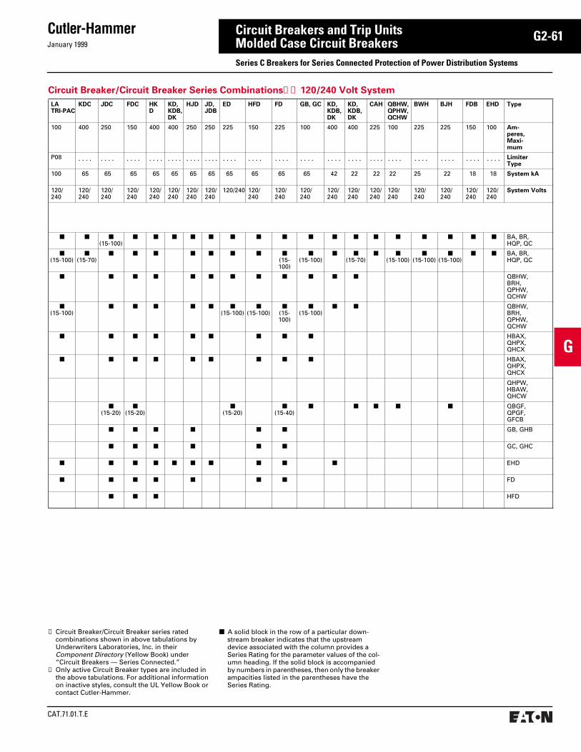
January 1999
Cutler-Hammer
CAT.71.01.T.E
G2-61
G
Circuit Breakers and Trip UnitsMolded Case Circuit Breakers Series C Breakers for Series Connected Protection of Power Distribution Systems
Circuit Breaker/Circuit Breaker Series Combinations➀➁ 120/240 Volt System
LATRI-PAC
KDC JDC FDC HKD
KD, KDB,DK
HJD JD, JDB
ED HFD FD GB, GC KD, KDB,DK
KD, KDB, DK
CAH QBHW, QPHW,QCHW
BWH BJH FDB EHD Type
100 400 250 150 400 400 250 250 225 150 225 100 400 400 225 100 225 225 150 100 Am-peres, Maxi-mum
P08 . . . . . . . . . . . . . . . . . . . . . . . . . . . . . . . . . . . . . . . . . . . . . . . . . . . . . . . . . . . . . . . . . . . . . . . . . . . . Limiter Type
100 65 65 65 65 65 65 65 65 65 65 65 42 22 22 22 25 22 18 18 System kA
120/240
120/240
120/240
120/240
120/240
120/240
120/240
120/240
120/240 120/240
120/240
120/240
120/240
120/240
120/240
120/240
120/240
120/240
120/240
120/240
System Volts
■ ■ ■(15-100)
■ ■ ■ ■ ■ ■ ■ ■ ■ ■ ■ ■ ■ ■ ■ ■ ■ BA, BR, HQP, QC
■(15-100)
■(15-70)
■ ■ ■ ■ ■ ■ ■ ■(15-100)
■(15-100)
■ ■(15-70)
■ ■(15-100)
■(15-100)
■(15-100)
■ ■ BA, BR, HQP, QC
■ ■ ■ ■ ■ ■ ■ ■ ■ ■ ■ ■ QBHW, BRH, QPHW, QCHW
■(15-100)
■ ■ ■ ■ ■ ■(15-100)
■(15-100)
■(15-100)
■(15-100)
■ ■ QBHW, BRH, QPHW, QCHW
■ ■ ■ ■ ■ ■ ■ ■ ■ HBAX, QHPX, QHCX
■ ■ ■ ■ ■ ■ ■ ■ ■ HBAX, QHPX, QHCX
QHPW, HBAW, QHCW
■(15-20)
■(15-20)
■(15-20)
■(15-40)
■ ■ ■ ■ ■ QBGF, QPGF, GFCB
■ ■ ■ ■ ■ ■ GB, GHB
■ ■ ■ ■ ■ ■ GC, GHC
■ ■ ■ ■ ■ ■ ■ ■ ■ ■ EHD
■ ■ ■ ■ ■ ■ ■ FD
■ ■ ■ HFD
➀ Circuit Breaker/Circuit Breaker series rated combinations shown in above tabulations by Underwriters Laboratories, Inc. in their Component Directory (Yellow Book) under “Circuit Breakers — Series Connected.”
➁ Only active Circuit Breaker types are included in the above tabulations. For additional information on inactive styles, consult the UL Yellow Book or contact Cutler-Hammer.
■ A solid block in the row of a particular down-stream breaker indicates that the upstream device associated with the column provides a Series Rating for the parameter values of the col-umn heading. If the solid block is accompanied by numbers in parentheses, then only the breaker ampacities listed in the parentheses have the Series Rating.
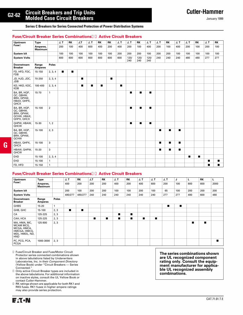
CAT.71.01.T.E
Cutler-HammerJanuary 1999
G2-62
G
Circuit Breakers and Trip UnitsMolded Case Circuit Breakers Series C Breakers for Series Connected Protection of Power Distribution Systems
The series combinations shown are UL recognized component rating only. Consult the equip-ment manufacturer for applica-ble UL recognized assembly combinations.
Fuse/Circuit Breaker Series Combinations➀➁ Active Circuit Breakers
UpstreamFuse➂
Type J, T RK J,T J, T RK RK J, T J, T RK J, T J, T RK J, T J, T RK J, T RK
Amperes, Maximum
200 100 400 600 400 200 400 200 100 400 200 100 400 200 100 200 100
System kA 100 100 100 100 100 100 200 200 200 100 200 200 100 100 100 100 100
System Volts 600 600 600 600 600 600 600 120/240
120/240
120/240
240 240 240 480 480 277 277
DownstreamBreaker
Range Amperes
Poles
FD, HFD, FDC, FDB
15-150 2, 3, 4 ■ ■
JD, HJD, JDC, JDB
70-250 2, 3, 4 ■ ■
KD, HKD, KDC, KDB
100-400 2, 3, 4 ■ ■ ■ ■
BA, BR, HQP, QC, QBHW, BRH, QPHW, HBAX, QHPX, QHCX
15-70 1 ■ ■ ■
BA, BR, HQP, QC, QBHW, BRH, QPHW, QCHW, HBAX, QHPX, QHCX
15-100 2 ■ ■ ■
QHPW, HBAW, QHCW
15-30 1, 2 ■ ■ ■
BA, BR, HQP, QC, QBHW, BRH, QPHW, QCHW
15-100 2, 3 ■ ■ ■
HBAX, QHPX, QHCX
15-100 3 ■ ■ ■
HBAW, QHPW, QHCW
15-20 3 ■ ■ ■
EHD 15-100 2, 3, 4 ■ ■
EHD 15-100 1 ■ ■
FD, HFD 15-150 1 ■ ■
➀ Fuse/Circuit Breaker and Fuse/Motor Circuit Protector series connected combinations shown in above tabulations listed by Underwriters Laboratories, Inc. in their Component Directory (Yellow Book) under “Circuit Breakers — Series Connected.”
➁ Only active Circuit Breaker types are included in the above tabulations. For additional information on inactive styles, consult the UL Yellow Book or contact Cutler-Hammer.
➂ RK ratings shown are applicable for both RK1 and RK5 fuses. RK1 fuses in higher ampere ratings may also provide series protection.
Fuse/Circuit Breaker Series Combinations➀➁ Active Circuit Breakers
UpstreamFuse➂
Type J, T RK J,T RK J, T RK J, T J, T J, T J L RK L
Amperes,Maximum
400 200 200 200 400 200 400 600 200 100 800 600 2000
System kA 200 100 200 200 100 100 200 100 65 100 200 200 200
System Volts 480/277 480/277 240 240 240 240 240 240 277 277 480 600 480
DownstreamBreaker
Range Amperes
Poles
GHBS 15-20 1 ■ ■
GHB, GHC 15-100 2, 3 ■ ■
CA 125-225 2, 3 ■ ■
CAH, HCA 125-225 2, 3 ■ ■ ■ ■ ■ ■
MA, HMA, MC, MCAM MCG, MCGA, HMCA, HMCGA, HMCG, MDL, HMDL, ND, HND
125-800 2, 3 ■ ■
PC, PCG, PCA, PCGA
1000-3000 2, 3 ■

January 1999
Cutler-Hammer
CAT.71.01.T.E
G2-63
G
Circuit Breakers and Trip UnitsMolded Case Circuit Breakers Series C Breakers for Series Connected Protection of Power Distribution Systems
Fuse/Circuit Breaker Series Combinations➀➁ Active Circuit Breakers
UpstreamFuse➂
Type J, T RK L RK J, T RK L RK J, T RK RK RK J, T RK J, T RK
Amperes, Maximum
600 400 1200 600 600 400 1200 600 400 100 200 200 400 100 400 100
System kA 200 200 100 100 200 200 100 100 200 200 100 100 100 200 200 200
System Volts 600 600 600 600 480 480 480 240 120/240
120/240
120/240
277 277 240 240 480/277
DownstreamBreaker
Range Amperes
Poles
LC, LCA, LCG, LCGA, HLC, HLCA, HLCG, HLCGA
125-600 2, 3 ■ ■ ■ ■
LC, LCA, LCG, LCAG, HLC, HLCA, HLCG, HLCGA
74-400 2, 3 ■ ■ ■ ■
GB, GC, GHB, GHC
15-100 1 ■ ■ ■
GHB, GHC 15-100 1 ■ ■
GB, GC, GHB, GHC
15-100 2, 3 ■ ■
GHB, GHC 15-100 2, 3 ■
MA, HMA, MC, MCA, MCG, MCGA, HMCA, HMCGA, HMCG, MDL, HMDL, ND, HND
125-800 2, 3 ■ ■
NB, NC, NCA, NCG, NCGA, HNB, HNC, HNCA, HNCG, HNCGA, MDL, HMDL, ND, HND
600-1200 2, 3 ■
➀ Fuse/Circuit Breaker and Fuse/Motor Circuit Protector series connected combinations shown in above tabulations listed by Underwriters Laboratories, Inc. in their Component Directory (Yellow Book) under “Circuit Breakers — Series Connected.”
➁ Only active Circuit Breaker types are included in the above tabulations. For additional information on inactive styles, consult the UL Yellow Book or contact Cutler-Hammer.
➂ RK ratings shown are applicable for both RK1 and RK5 fuses. RK1 fuses in higher ampere ratings may also provide series protection.

CAT.71.01.T.E
Cutler-HammerJanuary 1999
G2-64
G
Circuit Breakers and Trip UnitsMolded Case Circuit Breakers Typical Specifications
Molded Case Protective DevicesA. Protective devices shall be molded case
circuit breakers with inverse time and instantaneous tripping characteristics and shall be Cutler-Hammer Series C or approved equal.
B. Circuit breakers shall be operated by a toggle-type handle and shall have a quick-make, quick-break over-center switching mechanism that is mechanically trip-free. Automatic tripping of the breaker shall be clearly indicated by the handle position. Contacts shall be nonwelding silver alloy and arc extinction shall be accomplished by means of DE-ION arc chutes. A push-to-trip button on the front of the circuit breaker shall provide a local manual means to exercise the trip mechanism.
C. Circuit breakers shall have a minimum symmetrical interrupting capacity as indicated on the drawings.
D. Circuit breakers 150-, 250- [400-] [600-] ampere frame and below shall be Cutler-Hammer Series C with thermal-magnetic trip units and inverse time-current characteristics.
For electronic type trip units insert trip units into paragraph E from section G3
E. Circuit breakers [400-] [600-] ampere through 1200-ampere frame shall be Cutler-Hammer Series C with micropro-cessor-based RMS sensing trip units.
For 1600-ampere through 2500-ampere breakers insert applicable trip unit specifi-cation into paragraph F from section G3.
F. Circuit breakers 1600-ampere through 2500-ampere frame shall be Cutler-Hammer Series C with microprocessor-based RMS sensing trip units.
G. Ground fault protection shall be provided where indicated.
H. Where indicated circuit breakers shall be UL listed for series application.
I. Where indicated circuit breakers shall be current limiting.
J. Where indicated provide UL listed circuit breakers for applications at 100% of their continuous ampere rating in their intended enclosure.
For a complete product specification in CSI format, see Cutler-Hammer Product Specification Guide, section 16475.


![12-22 Molded Case Circuit Breakers Cutler-Hammer Molded Case Circuit Breakers 10-225 Amperes F-Frame Cutler-Hammer January 2001 Vol. 1,Ref. No. [0488] Table 12-35. Type FD Thermal-Magnetic](https://static.fdocuments.in/doc/165x107/5b0957e87f8b9a93738db33b/12-22-molded-case-circuit-breakers-cutler-hammer-molded-case-circuit-breakers-10-225.jpg)


![Cutler-Hammer - Amazon Simple Storage Service · 12-170 Molded Case Circuit Breakers Internal Accessories Shunt Trip Cutler-Hammer January 2001 Vol. 1, Ref. No. [0636] Table 12-335.](https://static.fdocuments.in/doc/165x107/5b1a83db7f8b9a46258d8d6f/cutler-hammer-amazon-simple-storage-service-12-170-molded-case-circuit-breakers.jpg)
![Cutler-Hammer - Amazon S3...Cutler-Hammer January 2001 Vol. 1, Ref. No. [0485] Molded Case Circuit Breakers 10-225 Amperes F-Frame 12-19 Contents Description Product Description Technical](https://static.fdocuments.in/doc/165x107/5e571a0eaa6fee6e62434437/cutler-hammer-amazon-s3-cutler-hammer-january-2001-vol-1-ref-no-0485.jpg)