Customer Support Information - Black Box...
72
KV7118SA KV7148FA FREE tech support 24 hours a day, 7 days a week: Call 724-746-5500 or fax 724-746-0746. Mailing address: Black Box Corporation, 1000 Park Dr., Lawrence, PA 15055-1018 World-Wide Web: www.blackbox.com • E-mail: [email protected] © Copyright 2002. Black Box Corporation. All rights reserved. Customer Support Information: R R AUGUST 1998
-
Upload
vuongxuyen -
Category
Documents
-
view
218 -
download
0
Transcript of Customer Support Information - Black Box...

KV7118SAKV7148FA
FREE tech support 24 hours a day, 7 days a week: Call 724-746-5500 or fax 724-746-0746.Mailing address: Black Box Corporation, 1000 Park Dr., Lawrence, PA 15055-1018
World-Wide Web: www.blackbox.com • E-mail: [email protected]© Copyright 2002. Black Box Corporation. All rights reserved.
Customer Support Information:
R
R
R
R
AUGUST 1998

1
THE SERVSWITCH™ FAMILY
Welcome to the ServSwitchTM Family!Thank you for purchasing a BLACK BOX® ServSwitch™ Brand KVM switch! Weappreciate your business, and we think you’ll appreciate the many ways that yournew ServSwitch keyboard/video/mouse switch will save you money, time, andeffort.
That’s because our ServSwitch family is all about breaking away from thetraditional, expensive model of computer management. You know, the one-size-fits-all-even-if-it-doesn’t model that says, “One computer gets one user station, nomore, no less.” Why not a single user station (monitor, keyboard, and mouse) formultiple computers—even computers of different platforms? Why not a pair ofuser stations, each of which can control multiple computers? Why not multipleuser stations for the same computer?
With our ServSwitch products, there’s no reason why not. We carry a broad lineof robust solutions for all these applications. Do you have just two PCs, and needan economical alternative to keeping two monitors, keyboards, and mice on yourdesk? Or do you need to share dozens of computers, including a mix of IBM® PC,RS/6000®, Apple® Macintosh®, Sun Microsystems®, and SGI® compatibles amongmultiple users with different access levels? Does your switch have to sit solidly on aworktable and use regular everyday cables? Or does it have to be mounted in anequipment rack and use convenient many-to-one cables? No matter how large orsmall your setup is, no matter how simple or how complex, we’re confident wehave a ServSwitch system that’s just right for you.
The ServSwitch™ family from Black Box—the one-stop answer for all your KVM-switching needs!
*This manual will tell you all about your new ServSwitch Elite™ unit, including
how to install, operate, and troubleshoot it. For an introduction to the ServSwitchElite, see Chapter 2. The ServSwitch Elite product codes covered in this manualare:
KV7118SAKV7148FA
This manual also includes information about the acessories with these productcodes (each comes with its own installation guide if ordered separately):
KV7150A RMK19EKV7160A RMK19E4KV7170A

2
SERVSWITCH ELITE™
TRADEMARKS USED IN THIS MANUAL
Apple and Macintosh are registered trademarks of Apple Computer, Inc.
Compaq is a registered trademark of Compaq Computer Corporation.
Hewlett-Packard, HP, and HP9000 are registered trademarks of Hewlett-Packard.
IBM, PC/AT, PS/2, RISC System/6000, and RS/6000 are registered trademarks of International Business Machines Corporation.
Logitech is a trademark of Logitech, Inc.
IntelliMouse and Microsoft are either registered tradmark or trademarks, of Microsoft Corporation in the United States and/or other countries.
SGI is a registered trademark of Silicon Graphics, Inc.
Sun Microsystems is a registered trademark of Sun Microsystems, Inc.
Any other trademarks mentioned in this manual are acknowledged to be the property of thetrademark owners.
DISCLAIMER
The information in this manual is subject to change without notice. Themanufacturer shall not be liable for technical or editorial errors or omissionscontained herein; nor is it liable for incidental or consequential damages resultingfrom the furnishing, performance, or use of this material.

3
FCC/IC STATEMENTS
FEDERAL COMMUNICATIONS COMMISSIONAND
CANADIAN DEPARTMENT OF COMMUNICATIONSRADIO FREQUENCY INTERFERENCE STATEMENTS
This equipment generates, uses, and can radiate radio frequency energy and if notinstalled and used properly, that is, in strict accordance with the manufacturer’sinstructions, may cause interference to radio communication. It has been testedand found to comply with the limits for a Class A computing device in accordancewith the specifications in Subpart B of Part 15 of FCC rules, which are designed toprovide reasonable protection against such interference when the equipment isoperated in a commercial environment. Operation of this equipment in aresidential area is likely to cause interference, in which case the user at his ownexpense will be required to take whatever measures may be necessary to correct theinterference.
Changes or modifications not expressly approved by the party responsible forcompliance could void the user’s authority to operate the equipment.
Shielded cables must be used with this equipment to maintain compliance withradio frequency energy emission regulations and ensure a suitably high level ofimmunity to electromagnetic disturbances.
This digital apparatus does not exceed the Class A limits for radio noise emission from digitalapparatus set out in the Radio Interference Regulation of the Canadian Department ofCommunications.
Le présent appareil numérique n’émet pas de bruits radioélectriques dépassant les limitesapplicables aux appareils numériques de la classe A prescrites dans le Règlement sur lebrouillage radioélectrique publié par le ministère des Communications du Canada.

4
SERVSWITCH ELITE™
BZT COMPLIANCE STATEMENT
BZT HINWEIS
Hiermit wird bescheinigt, daß dieses Gerät in Übereinstimmung mit denBestimmugen der BMPT-AmtsblVfg 243/1991 funk-enstört ist. Dervorschriftsmäßige Betrieb mancher Gerät (z.B. Meßsender) kann allerdingsgewissen Einschränkungen unterliegen. Beachten Sie deshalb die Hinweise in derBedienungsanleitung.
Dem Bundesamt für Zulassungen in der Telekommunikation wurde dasInverkehrbringen dieses Geräts angezeigt und die Berechtigung zur Überprüfungder Serie auf die Einhaltung der Bestimmugen eingeräumt.

5
NOM STATEMENT
NORMAS OFICIALES MEXICANAS (NOM)ELECTRICAL SAFETY STATEMENT
INSTRUCCIONES DE SEGURIDAD
1. Todas las instrucciones de seguridad y operación deberán ser leídas antes deque el aparato eléctrico sea operado.
2. Las instrucciones de seguridad y operación deberán ser guardadas parareferencia futura.
3. Todas las advertencias en el aparato eléctrico y en sus instrucciones deoperación deben ser respetadas.
4. Todas las instrucciones de operación y uso deben ser seguidas.
5. El aparato eléctrico no deberá ser usado cerca del agua—por ejemplo, cercade la tina de baño, lavabo, sótano mojado o cerca de una alberca, etc..
6. El aparato eléctrico debe ser usado únicamente con carritos o pedestales quesean recomendados por el fabricante.
7. El aparato eléctrico debe ser montado a la pared o al techo sólo como searecomendado por el fabricante.
8. Servicio—El usuario no debe intentar dar servicio al equipo eléctrico más alláa lo descrito en las instrucciones de operación. Todo otro servicio deberá serreferido a personal de servicio calificado.
9. El aparato eléctrico debe ser situado de tal manera que su posición nointerfiera su uso. La colocación del aparato eléctrico sobre una cama, sofá,alfombra o superficie similar puede bloquea la ventilación, no se debe colocaren libreros o gabinetes que impidan el flujo de aire por los orificios deventilación.
10. El equipo eléctrico deber ser situado fuera del alcance de fuentes de calorcomo radiadores, registros de calor, estufas u otros aparatos (incluyendoamplificadores) que producen calor.
11. El aparato eléctrico deberá ser connectado a una fuente de poder sólo deltipo descrito en el instructivo de operación, o como se indique en el aparato.

6
SERVSWITCH ELITE™
12. Precaución debe ser tomada de tal manera que la tierra fisica y la polarizacióndel equipo no sea eliminada.
13. Los cables de la fuente de poder deben ser guiados de tal manera que nosean pisados ni pellizcados por objetos colocados sobre o contra ellos,poniendo particular atención a los contactos y receptáculos donde salen delaparato.
14. El equipo eléctrico debe ser limpiado únicamente de acuerdo a lasrecomendaciones del fabricante.
15. En caso de existir, una antena externa deberá ser localizada lejos de las lineasde energia.
16. El cable de corriente deberá ser desconectado del cuando el equipo no seausado por un largo periodo de tiempo.
17. Cuidado debe ser tomado de tal manera que objectos liquidos no seanderramados sobre la cubierta u orificios de ventilación.
18. Servicio por personal calificado deberá ser provisto cuando:
A: El cable de poder o el contacto ha sido dañado; u
B: Objectos han caído o líquido ha sido derramado dentro del aparato; o
C: El aparato ha sido expuesto a la lluvia; o
D: El aparato parece no operar normalmente o muestra un cambio en sudesempeño; o
E: El aparato ha sido tirado o su cubierta ha sido dañada.

7
TABLE OF CONTENTS
Contents
Chapter Page
1. Specifications ............................................................................................. 9
2. Introduction ............................................................................................. 112.1 Overview ............................................................................................ 112.2 Key Features ...................................................................................... 12
2.2.1 Flexibility and Versatility ........................................................ 122.2.2 Improved Video Quality ......................................................... 122.2.3 Ease of Use and Maintenance ................................................ 12
2.3 Possible System Configurations ........................................................ 132.3.1 Single ServSwitch Elite Systems .............................................. 132.3.2 Multiple ServSwitch Elite Systems .......................................... 14
3. Installation ................................................................................................ 173.1 Unpacking the Switch/The Complete Package .............................. 173.2 Setting DIP Switch F (4x8 Model Only) .......................................... 173.3 Rackmounting Switches (Optional) ................................................ 183.4 The Installation Procedure .............................................................. 20
3.4.1 Placing the Unpowered Switches ........................................... 203.4.2 Cascading Switches (Optional) .............................................. 203.4.3 Connecting the Console Equipment ..................................... 233.4.4 Connecting the Computers .................................................... 263.4.5 Connecting the Power ............................................................ 27
3.5 Initial Power-Up: Turning On the System ....................................... 28
4. Operation and Configuration ................................................................. 304.1 Basic Operation ................................................................................. 31
4.1.1 Switching Between Computers ............................................... 314.1.2 Checking Port/Computer Status ........................................... 35
4.2 Higher-Level Operation and Configuration: The FUNCTIONS Menu ............................................................. 36
4.2.1 Scanning Computers in the System ....................................... 374.2.2 Displaying Version Information and Device Settings ........... 384.2.3 Saving the Hardware Configuration ...................................... 394.2.4 Resetting the Mouse and Keyboard Ports .............................. 394.2.5 Using Broadcast Mode (Single-User Model Only) ............... 404.2.6 Setting a Scan Pattern ............................................................. 43

8
SERVSWITCH ELITE™
Contents (continued)
Chapter Page
4. Operation and Configuration (continued)4.2 Higher-Level Operation and Configuration:
The FUNCTIONS Menu (continued)4.2.7 Assigning Unique Names to the Computers and
Slaves in the System ......................................................... 454.2.8 Changing the Menu Attributes ............................................ 474.2.9 Changing the Attributes of the Ststus Flag .......................... 504.2.10 Assigning Specific Device Types .......................................... 524.2.11 Setting Security Options ....................................................... 53
4.3 Resetting the ServSwitch Elite .......................................................... 564.4 Making Connections Under Power ................................................. 564.5 Power-Outage Recovery .................................................................... 56
5. Troubleshooting ...................................................................................... 576.1 Common Problems ........................................................................... 576.2 Calling Black Box .............................................................................. 596.3 Shipping and Packaging ................................................................... 59
Appendix A: Keyboard Commands for the On-Screen Display ................... 60
Appendix B: Upgrading the Firmware .......................................................... 61
Appendix C: RS/6000 Handling ................................................................... 63
Appendix D: Interface Pinouts ...................................................................... 64D.1 IBM PC/AT Compatible Keyboard .................................................. 64D.2 IBM PC/AT Compatible Serial Mouse ............................................ 64D.3 IBM PS/2 Compatible Keyboard and Mouse .................................. 65D.4 IBM Video Graphics Array (VGA),
Super Video Graphics Array (SVGA) ......................................... 66

9
CHAPTER 1: Specifications
1. SpecificationsCompliance — EMI/RFI: CE; CISPER-A; FCC Part 15 Subpart B Class A,
DOC Class/MDC classe A;Electrical Safety: UL® 1950, cUL, TUV/GS, EN 60950
Standards — VGA, SVGA, and XGA video
Compatibility — Video: VGA, SVGA, XGA, GTX, or GTX1XX; alsoIBM RS/6000 and HP9000, although RS/6000 requiresspecial cabling and RS/6000 and HP9000 sync-on-green applications require video adapters;
Keyboard: IBM PC/AT or PS/2 compatible (connectinga PC/AT keyboard requires an adapter such as ourproduct code FA211);
Mouse: IBM PS/2 compatible two-button, MicrosoftIntelliMouse, or Logitech™ PS/2 compatible 2- or3-button
Interfaces — Video: VGA;Keyboard and mouse: IBM PS/2 compatible
Resolution — Up to 1024 x 768 noninterlaced
MaximumDistance — 12 ft. (3.6 m) of extension cabling to any attached
keyboard, monitor, and mouse;50 ft. (15.2 m) of extension cabling to any attached CPU
or cascaded ServSwitch Elite unit
User Controls — Keyboard/on-screen-menu commands;(1) Rear-mounted rocker switch for power;(1) Rear-mounted reset pushbutton;KV7148FA only: (1) Internal DIP switch for port-
contention handling
Indicators — On-screen windows and on-screen status-flag box

10
SERVSWITCH ELITE™
Connectors — All rear-mounted:(1) RJ-45 female AUX connector;(1) IEC 320 male power inlet;(8) sets of:
(1) HD15 female to CPU’s video port;(2) 6-pin mini-DIN female:
(1) to CPU’s keyboard port,(1) to CPU’s mouse port;
For each computer port:(1) HD15 female to monitor;(2) 6-pin mini-DIN female:
(1) to keyboard, (1) to mouse;KV7118SA: (1) set;KV7148FA: (4) sets
MTBF — 100,000 hours (calculated)
TemperatureTolerance — 50 to 104˚F (10 to 40˚C)
HumidityTolerance — 5 to 90% noncondensing
Enclosure — Cold-rolled steel
Power — Input: 100 to 120 VAC or 200 to 240 VAC at 50 to 60 Hzfrom utility-power outlet, through detachable powercord and IEC 320 male inlet;
Consumption: 30 watts maximum
Size — KV7118SA:1.8"H (1U) x 17"W x 10.8"D (4.4 x 43.2 x 27.4 cm);
KV7148FA:3.5"H (2U) x 17"W x 10.8"D (8.9 x 43.2 x 27.4 cm)
Weight — KV7118SA: 9.1 lb. (4.1 kg);KV7148FA: 10.3 lb. (4.6 kg)

11
CHAPTER 2: Introductiom
2. Introduction
2.1 OverviewThe ServSwitch Elite is another great space- and effort-saving solution in theServSwitch™ family of KVM switches from Black Box. It is 100% pin-for-pincompatible with the current generation of KVM switches by Compaq® and Hewlett-Packard®, so it’s just right for adding to your existing Compaq or HP® environment.
It’s also “modular” in that it can be configured and installed in differentquantities and locations to suit the switching needs of a particular system. You canuse multiple Switches to expand the system and connect user consoles to any of upto 64 computers.
With one single-user (our product code KV7118SA) ServSwitch Elite, users at asingle user console (monitor, keyboard, and mouse station) can access any of asmany as eight IBM® PC, IBM RISC System/6000® (RS/6000®), or HP9000®
compatible computers. With one 4x8 (KV7148FA) model, users at up to four userconsoles can access any of up to eight such computers. Both versions are enclosedin space-efficient cases to save space on your desktop or in your rack: 1U (1.8",4.4 cm) high for the single-user model, 2U (3.5", 8.9 cm) high for the 4x8 model.And you can attach as many as eight “slave” units of either version to a “master”unit of either version to create a cascaded system with a capacity for 64 computers.
Switching between (also called “selecting”) computers is accomplished by typinga command at the keyboard. The selected computer receives characters typed atthe keyboard and displays its video output on your monitor. You can use the mouse(which is optional) to interact with the graphic interface that the selectedcomputer displays on the monitor. The ServSwitch Elite works independently ofthe attached computers’ operating systems, so it doesn’t matter if the computersare running different operating systems.

12
SERVSWITCH ELITE™
2.2 Key Features
2.2.1 FLEXIBILITY AND VERSATILITY
The ServSwitch Elite is compatible with several types of keyboards and mice,including:
• Industry-standard IBM PS/2® compatible keyboards and mice, includingLogitech™ 2- and 3-button types;
• RS/6000 and HP9000 keyboards and mice;
• Microsoft® IntelliMouse® compatible mice;
• With the proper interface adapters, IBM PC/AT® compatible keyboards andserial mice (serial mice must be clearly identified as “mouse-port compatible”).
The Switch is also compatible with computers that have any of several major typesof peripheral-I/O ports, including:
• PS/2 compatible (including RS/6000 and HP9000) keyboard and mouseports, or,
• Through our PC/AT Serial Mouse Converter Kit (KV7150A), PC/AT keyboardports and RS-232 serial mouse ports.
2.2.2 IMPROVED VIDEO QUALITY
The ServSwitch Elite supports standard display adapters and high-resolution video.Specifically, they support analog VGA, SVGA, and XGA video, as well as—with theRS/6000 (KV7160A) or HP9000 (KV7170A) Converter Kit respectively—RS/6000or HP9000 video. The Switch can drive video at a maximum resolution of 1024 by768 pixels across a 50-foot (15.2-m) video cable.
2.2.3 EASE OF USE AND MAINTENANCE
• On-Screen DisplayThe Switch’s on-screen menus display a variety of system-related informationon any console monitor, including power-up test data and configurationmenus.
• Programmable ScanningScanning lets you observe system performance by sequentially displaying thevideo from any or all of the computers in the system on your monitor.Programable scanning allows you to select which computers to include and tospecify the duration of the connection.

13
CHAPTER 2: Introductiom
• Configuration NVRAM.The ServSwitch Elite uses nonvolatile RAM (NVRAM), which makes it easy toconfigure the Switch using commands entered from your keyboard. TheNVRAM stores the resulting configuration until you decide to change theconfiguration settings again, even if the Switch is turned off or unplugged.
• External Reset SwitchIf keyboard or mouse communication is disrupted, you can push this button toreinitialize the keyboard and mouse without turning the Switch off.
• Password ProtectionProtects network resources by locking the keyboard and monitor.
• BroadcastingSends keyboard and/or mouse input to multiple computers simultaneously,
• Remote Keypad (optional, special quote)A remote keypad for the ServSwitch Elite, consisting of a handheld controllerattached to a 2-ft. (0.6-m) cable terminated with an RJ-45 plug, is available on aspecial-quote basis. When you connect it to the Switch’s rear-panel AUXconnector, it can take the place of the keyboard for the purpose of selectingcomputers on the Switch. Contact Black Box Technical Support for moreinformation.
2.3 Possible System ConfigurationsServSwitch Elites can be used in various system configurations to meet the needs oforganizations operating computer networks of various sizes:
• Single Servswitch Elites can be used to connect up to eight computers
• Multiple Switches can be cascaded to connect up to 64 computers
2.3.1 SINGLE SERVSWITCH ELITE SYSTEMS
In systems involving only one ServSwitch Elite, the keyboard, monitor, and mousecables of each user console are connected directly to the Switch by their respectivecables, as shown in Figure 2-1 (for the single-user model) and Figure 2-2 (for the4x8 model) on the next page. The Switch then connects to the computers (asmany as eight of them) through multiple sets of keyboard-, mouse-, and video-extension cables.

14
SERVSWITCH ELITE™
Figure 2-1. A system with one single-user Switch.
Figure 2-2. A single-4x8-Switch system.
Monitor Monitor
Console 1 . . . . . . . . . . . . . . . . . . . . . Console 4
Keyboard
Keyboard
Mouse
Mouse
Keyboard-, Mouse-,and Video-
Extension Cables
CPUs
4x8 SERVSWITCH ELITE (KV7148FA)
Monitor
SINGLE-USER SERVSWITCH ELITE (KV7118SA)
Keyboard Mouse
CPUs
Keyboard-,Mouse-, and
Video-Extension
Cables

15
CHAPTER 2: Introductiom
2.3.2 MULTIPLE SERVSWITCH ELITE SYSTEMS
For systems with a large number of computers, ServSwitch Elites can be cascaded ina master/slave configuration to connect up to 64 computers. You can cascadeSwitches by connecting a “slave” (subsidiary) unit’s console port to one of thecomputer ports on the “master” (primary) unit, as shown in Figure 2-3 on the nextpage (for the single-user model) or Figure 2-4 on page 16 (for the 4x8 model).Multiple slave Switches can be cascaded from the master in this manner. For moreinformation on cascaded systems, see Section 3.4.2.
Figure 2-3. A cascaded “single-user”-Switch system.
Monitor
MASTER SINGLE-USER SERVSWITCH ELITE
SLAVE SINGLE-USER SERVSWITCH ELITE
KeyboardMouse
CPUs
CPUs
Keyboard-,Mouse-, and
Video-Extension
Cables
Keyboard-,Mouse-, and
Video-Extension
Cables

16
SERVSWITCH ELITE™
Figure 2-4. A cascaded system with a 4x8 Switch master.
Monitor Monitor
Console 1 . . . . . . . . . . . . Console 4
Keyboard
KeyboardMouse
Mouse
Keyboard-, Mouse-,and Video-
Extension Cables
CPUs
MASTER 4x8 SWITCH
SLAVE SINGLE-USER SWITCH

17
CHAPTER 3: Installatiom
3. Installation
3.1 Unpacking the Switch/The Complete PackageWe ship the ServSwitch Elite in packaging designed to protect the system duringshipping and handling. We recommend that you save the carton and packingmaterials in case you need to transport the Switch later.
The complete ServSwitch Elite system you should have received includes:
• The ServSwitch Elite main unit.
• Its power cord.
• This manual.
Please contact Black Box right away if anything is missing or arrived damaged.
3.2 Setting DIP Switch F (4x8 Model Only)In its factory-default “cooperative” state, the ServSwitch Elite 4x8 (KV7148FA)always resolves port/slave contention in favor of existing connections: Even if aconsole is idle, no matter how long it has been in control of a computer port, noother console can connect either to that port (if the port’s on a single or masterSwitch) or to any port on that unit (if the port’s on a cascaded slave Switch). Ifanother console tries to do so, the attempt is denied and the other consolebecomes “deselected” (not connected to any port). For example, suppose the userat Console A has selected computer port 3 and the user at Console B has selectedport 6. If Console A’s user tries to select port 6, the request will be ignored andConsole A will lose its connection to port 3, becoming disonnected from all of thecomputer ports until its user selects another.
If this is OK with you, go on to Section 3.3. But if you would like your 4x8 Switchto always resolve port/slave contention in favor of new connections instead—sothat, in the above example, Console A would get port 6 and Console B would bedisplaced (not connected to any computer port, with its monitor blanked)—youneed to move its DIP switch F to the “preemptive” setting. Following the first partof the procedure for upgrading the Switch’s firmware (see Appendix B), open thelittle panel on the bottom of the unit, exposing an area of the circuit board thatcontains a block of four DIP switches. Move the switch marked “1-1” on the left endof the block to the “ON” position and close the panel back up again. Your Switch isnow set to “preemptive” mode, and will allow any console to select any computerport at any time, even if doing so disrupts previously established console-to-computer-port connections.

18
SERVSWITCH ELITE™
3.3 Rackmounting Switches (Optional)Rackmount kits are available if you want to mount either model of the ServSwitchElite in an EIA-standard 19" equipment rack. (This is especially useful if you wantto attach the Switch to computers that are already mounted in the same oradjoining racks.) Figure 3-1 on the next page shows how to attach the mountingbrackets from the RMK19E kit to the single-user Switch; Figure 3-2 on the nextpage shows how to attach the brackets from the RMK19E4 kit to the 4x8 Switch.
Follow safety measures when you install this equipment:
• Before you mount a Switch, make sure it is turned off and unplugged.
• Before you mount a Switch or other components in a rack cabinet, stabilizethe cabinet in a permanent location. Start rackmounting your equipment atthe bottom of the cabinet, then work your way to the top. Avoid unevenloading or overloading of cabinets.
CAUTION!Do not exceed your cabinets’ load rates. Overloading or uneven loadingof a cabinet might result in shelf or cabinet failure, causing equipmentdamage and possibly personal injury.
When you do connect the ServSwitch Elite to a power source,connect it only to the type of power supply specified on the unit’shousing. Do not exceed the current or voltage capacity of the Switch orof your site’s circuits. Overloaded power sources, extension cords, etc.,pose fire and shock hazards.
Take these steps to rackmount your Switch:
1. Line up the holes in the “long side” of the Kit’s side brackets with thescrewholes in the sides of the ServSwitch Elite.
2. With an Allen wrench, fasten the mounting brackets to the Switch using two ofthe included 8-32 x 3⁄8" button-head socket-cap screws per side.
3. Attach the included rack nut/holders to the mounting rail of the rack so thatthey are positioned on the inside of the cabinet.
4. Mount the Switch assembly to the cabinet by matching the holes or grooves onthe “short side” of each bracket to an appropriate set of matching holes onyour equipment rack, then inserting the included 10-32 x 1⁄2" Phillips truss-headscrews through the holes or grooves in the bracket and the holes in themounting rail, into the rack nut/holders, then tightening the screws to securethe assembly in place.

19
CHAPTER 3: Installatiom
Figure 3-1. Rackmounting the single-user Switch with the RMK19E kit.
Figure 3-2. Rackmounting the 4x8 Switch with the RMK19E4 kit.

20
SERVSWITCH ELITE™
3.4 The Installation ProcedureUse the procedures described in the following subsections to install yourServSwitch Elite system. Refer to Figure 3-6 (for the single-user model) andFigure 3-7 (for the 4x8 model) on page 24 for general guidelines about whereSwitch components are and what they’re for.
3.4.1 PLACING THE UNPOWERED SWITCHES
Before you do anything else, take these steps:
1. Make sure that each ServSwitch Elite you plan to install is turned off andunplugged.
2. Place any Switches that you haven’t already rackmounted (see Section 3.3) inyour desired location(s).
3.4.2 CASCADING SWITCHES (OPTIONAL)
A cascaded ServSwitch Elite system configuration allows the greatest flexibility andcapacity. A cascaded configuration can include up to nine Switches and as many as64 computers: In a cascaded system, the Switch connected to the main console(s)becomes the master or primary Switch; a layer of slave or secondary Switches areconnected to the master Switch’s computer ports. One master can accommodateeight slaves; thus, on a system with eight computers connected to each of the eightslaves, the users on the master Switch’s console(s) can access 64 computers.
One thing you have to remember in a cascaded system is how the ports arenumbered. The ServSwitch Elite system treats slaves’ computer ports much likeports on a master or single Switch, but in the Switch’s on-screen menus, thenumbers of ports on a slave Switch are designated as “digit1-dash-digit2,” where“digit1” is the slave’s port on the master and “digit2” is the computer port on theslave. For example, a computer connected to Port 2 on a slave Switch which isconnected to Port 1 on a master Switch would be numbered “1-2.”
When you’re finished installing your system, you might find it helpful to assign aname to each slave Switch (see Sections 4.2.7 and 4.2.10).

21
CHAPTER 3: Installatiom
To connect a cascaded ServSwitch Elite system, take these steps, referring toFigures 3-4 and 3-5 on the next page:
1. Plug keyboard-, mouse-, and video-extension cables into a set of consoleconnectors on the rear panel of the slave Switch. If your slave is a single-userunit, the keyboard, mouse, and monitor connectors will be the only consoleconnectors you have to choose from. If your slave is a 4x8 unit, werecommend that you use the “Console A” connectors.
NOTEYou can have “local” consoles connected to the other consoleconnectors on a slave 4x8 Switch. These consoles will contend with themaster’s console(s) for access to the CPU ports on that slave, but theywill not be able to access CPU ports on the master or on any otherslaves.
2. Plug the other ends of your keyboard- and mouse-extension cables into the6-pin mini-DIN sockets marked “K” and “M,” respectively, below one of thenumbered port labels on the rear panel of the master Switch. Plug the otherend of the video-extension cable into the associated HD15 female VGAconnector. (You might want to bundle and label these cables for easyidentification.)
For your cascade connections, we suggest that you start with CPU port“One” on the master Switch and use progressively higher-numbered ports asnecessary.
NOTELater, once you’ve finished installing your ServSwitch Elite system andit’s operational, you’ll be able to connect a slave Switch to your masterSwitch while the system is running, if necessary. (This can be usefulwhen you’re trying to isolate problems with minimum disruption to thesystem.) Because the master Switch interprets the keyboard connectionas the slave Switch powering up, you must first connect the slave’smouse- and video-extension cables, then the keyboard-extension cable.
This completes the physical installation of your cascade. Later, however, after thefully installed system has been powered up, you must tell the master Switch whichof its CPU ports are hosting slave Switches instead of computers, or the systemwon’t work. To do so, follow the directions in Section 4.2.10. Also, you mustconfigure your ServSwitch Elite system through the master Switch; see the note onpage 30.

22
SERVSWITCH ELITE™
Figure 3-4. Cascaded ServSwitch Elite system with a single-user master Switch.
Figure 3-5. Cascaded ServSwitch Elite system with a 4x8 master Switch.
Master Switch—CPU ports remainlogically numbered 1 through 8
Slave Switch—CPU ports becomelogically numbered 1-1 through 1-8
Keyboard-,Mouse-,
and Video-Extension
Cables
CPUPort 1
ConsolePort
Master Switch—CPU ports remainlogically numbered 1 through 8
Slave Switch—CPU ports becomelogically numbered 1-1 through 1-8
Keyboard-, Mouse-, andVideo-Extension Cables
CPUPort 1
ConsolePort

23
CHAPTER 3: Installatiom
3.4.3 CONNECTING THE CONSOLE EQUIPMENT
Each ServSwitch Elite console consists of a keyboard, a mouse or trackball, and amonitor. Note that the keyboard and mouse ports on the rear panel of the Switchare PS/2 style 6-pin mini-DIN connectors, and each monitor port is a VGA/SVGAstyle HD15 connector. This means that to attach a standard console, all you needto do is plug the monitor, keyboard, and mouse directly into the Switch. On asingle-user Switch, attach them to the monitor, keyboard, and mouse (console)connectors on the left end of the rear panel (see Figure 3-4 on the previous page);on a 4x8 Switch, attach them to the monitor, keyboard, and mouse connectors of“Console A,” “Console B,” “Console C,” or “Console D” on the top half of the rearpanel (see Figure 3-5 on the previous page).
If you need to run farther to your console equipment than its native cables willreach, you can use our special three-in-one User-Extension Cables (not included,our product code EHN409) or regular male-to-female keyboard-, mouse-, andvideo-extension cables (not included) to connect a standard monitor, keyboard,and mouse to a console port on the Switch. (The design of the User-ExtensionCable is shown in Figure 3-8 on page 25; it is available in a 10-foot [3-m] and30-foot [9-m] lengths, but we don’t recommend trying to run console-sideextension cabling farther than 12 ft. [3.6 m] in ServSwitch Elite applications,because 18 ft. [5.5 m] is all the farther some keyboards and mice can be from theSwitch and still operate.)
If any of your keyboard, mouse, or monitor cables have different connectors,some adapters and special cables are available from us as stock items and some areavailable on a special-quote basis (call Black Box Technical Support); some othersyou might have to get from the manufacturer of the peripheral you want toconnect. For more information about keyboard-, mouse-, and video-connectorpinouts, see Appendix D.
NOTESLater, once you’ve finished installing your ServSwitch Elite system andit’s operational, you’ll be able to connect a mouse and/or keyboard tothe Switch while the system is on. When you connect a new device, theSwitch will recognize the device and configure it to match the settingsof the currently selected computer. This will allow you to replace faileddevices without having to restart the system.
Whenever you make these kinds of changes to the system, youshould save its hardware-configuration settings. If you do not save thesettings, they will be lost when the Switch loses power or is turned off.For more information, see Section 4.2.3.

24
SERVSWITCH ELITE™
Figure 3-6. Rear panel of the single-user ServSwitch Elite.
Figure 3-7. Rear panel of the ServSwitch Elite 4x8.
To Monitor
To Monitor
From CPU 3’sVideo Port
From CPU 2’sVideo Port
PowerInlet
PowerInlet
PowerSwitch
PowerSwitch
To CPU 3’sKeyboard Port
To CPU 2’sKeyboard Port
To CPU 3’sMouse Port
To CPU 2’sMouse Port
FromKeyboard
From Keyboard
FromMouse
From Mouse
Auxiliary
Auxiliary

25
CHAPTER 3: Installatiom
Figure 3-8. The User-Extension and CPU-Extension Cables.
HD15
Centralvideostrand
Keyboard and mousestrands molded to sides
Cross-section:
9"(22.9cm)
10"(25.4cm)
6-Pinmini-DIN
6-Pinmini-DIN

26
SERVSWITCH ELITE™
3.4.4 CONNECTING THE COMPUTERS
Computer CPUs can be attached to the ServSwitch Elite through the CPU ports onits rear panel. Because the keyboard and mouse connectors on both the Switchand standard PCs are 6-pin mini-DIN female, and the video connectors on boththe Switch and standard PCs are HD15 female, you can use our special three-in-one CPU-Extension Cables (not included, our product code EHN408) or regularmale-to-male keyboard-, mouse-, and video-extension cables (not included) toconnect your standard computer CPUs to the Switch. (The design of the CPU-Extension Cable is shown in Figure 3-8 on the previous page; it is available in 5-foot[1.5-m], 10-foot [3-m], 30-foot [10-m], and 50-ft. [15-m] lengths.) Take these steps:
1. Make sure all of the CPUs are turned OFF and unplugged.
2. Run the keyboard- and mouse-extension cables from the CPU’s keyboard andmouse ports to the keyboard and mouse connectors (marked “K” and “M”respectively) of one of the Switch’s CPU ports.
3. Run the video-extension cable from the CPU’s video port to the videoconnector of the same CPU port on the Switch.
When you’re finished, you might want to bundle and label these cables for easyidentification.
If your computer has different keyboard-, mouse-, or video-port connectors, or ifit uses sync-on-green video, some adapters and special cables are available from usas stock items and some are available on a special-quote basis (call Black BoxTechnical Support); some others you might have to get from the manufacturer ofthe computer you want to connect.
For example, if you want to connect a computer with a serial mouse port, you’llneed to use the mouse adapter included with the KV7150A PC/AT Serial MouseConverter Kit (KV7150A) to translate the PS/2 mouse protocol into RS-232 serial-mouse signals.
Or, if you want to connect an IBM RS/6000\ with a 13W3 female video port,you’ll need our EHN6000-ELITE cable set. It consists of a 12-ft. (3.7-m) video-extension cable with an HD15 male connector on the Switch end and a 13W3 maleconnector on the RS/6000 end, plus a pair of standard 6-pin mini-DIN male-to-male PS/2 style extension cables for the keyboard and mouse connections.

27
CHAPTER 3: Installatiom
Thirdly, if you want to connect an RS/6000 workstation with a 3C3 female videoport or an HP9000 workstation, both of which use the “composite sync on green”video format, you’ll need to use the video adapter included with the RS/6000Converter Kit (KV7160A) or HP9000 Converter Kit (KV7170A) respectively. Thisadapter breaks the composite sync signal out onto separate horizontal and verticalsync lines, as is standard in regular PC video, and also improves the color balance.You’ll have to attach one of these adapters to the keyboard and video cablesbetween the Switch and the workstation’s CPU.
For more information about how the Switch handles RS/6000 computers, seeAppendix C. For more information about keyboard-, mouse-, and video-connectorpinouts, see Appendix D.
NOTESLater, once you’ve finished installing your ServSwitch Elite system andit’s operational, you’ll be able to connect additional computers to theSwitch while the system is on. When you power up a newly connectedCPU, the Switch will recognize it, and you should be able to select itright away.
Whenever you make these kinds of changes to the system, youshould save its hardware-configuration settings. If you do not save thesettings, they will be lost when the Switch loses power or is turned off.For more information, see Section 4.2.3.
3.4.5 CONNECTING THE POWER
To connect your ServSwitch Elite to AC power, first plug the IEC 320 outlet of theSwitch’s power cord into the IEC 320 power inlet on the back of the Switch. Plugthe other end—which should have a plug appropriate for your country or regionon it—into an AC outlet on a UPS (uninterruptible power supply), which wehighly recommend, or directly into a utility (mains) outlet if you don”t have a UPS.
Your Switch system should now be ready for operation. Go on to Section 3.5.

28
SERVSWITCH ELITE™
3.5 Initial Power-Up: Turning On the SystemThe first time you power up your ServSwitch Elite system, do it this way:
1. If you haven’t already done so, attach its power cord to the Switch and plugthe cord into a utility (mains) outlet.
2. Turn on your shared monitor(s).
3. Turn on the ServSwitch Elite by moving the power switch on its rear panelfrom the O position to the | position. This switch is on the far right end of theSwitch’s rear panel, as shown in Figures 3-6 and 3-7 on page 24.
4. Power up all of the attached CPUs (if you’re not sure how, see the computers’manuals).
The Switch has to be turned on before the computers because the computers’keyboard, mouse, and video drivers send device-configuration requests/commandsout of the corresponding ports. If the Switch is already ON, it can generatestandard responses to these transmissions so that the PCs can boot normally eventhough they aren’t physically connected to a keyboard, monitor, or mouse. If theSwitch is OFF, however, the PCs will probably either hang, crash, or boot into anabnormal state.
NOTELater, once your ServSwitch Elite system is fully installed andoperational, the Switch will help your computers recover from poweroutages. All of the computers attached to a Switch that are designed toreboot themselves automatically (without user intervention) will do sowhen power returns. The Switch generates responses to ensure that thereboot is successful and that the Switch is ready to switch betweencomputers when regular operation resumes.
The Switch also does a few other things while it helps the PCs to boot:
1. It detects the device settings requested by the PC drivers. (You will probablywant to save these settings to the Switch’s NVRAM, so that it loads themautomatically each time it powers up—see Section 4.2.3. You can manuallychange these NVRAM device settings later.)
2. It identifies the type of keyboard and mouse that are actually attached to eachof its consoles and puts them in their default states.
3. It displays revision information about its hardware and firmware on themonitor screen.

29
CHAPTER 3: Installatiom
4. The single-user ServSwitch Elite model automatically makes the startup-portselection: By default, the single-user model will switch its console toCPU port 1. The consoles’s monitor should display the number of the CPUport it’s connected to in a “status flag” box that looks something like this:
If the monitor doesn’t display rev-level info or a status flag, check to makesure that it’s plugged in, turned on, and connected to the Switch.
The 4x8 model will not make any automatic port selections; consoles A, B,C, and D will be deselected (not connected to any CPU port) at startup.

30
SERVSWITCH ELITE™
4. Operation and ConfigurationBasic operation of the ServSwitch Elite is performed through the keyboard and aseries of windows and menus that appear on the console display. Through thesemenus, you can perform functions such as switching between computers andchecking port/computer status. You can get into these menus by pressing the[Print Screen] key; once you do, you can communicate directly with the Switchusing your keyboard and monitor.
Table 4-1 on the next page shows how the ServSwitch Elite uses or affects certainkeys on the shared keyboard, especially in regards to the on-screen menu. Formore information on navigating the Switch’s on-screen display, refer toAppendix A.
NOTEIn ServSwitch Elite systems, a single press of the [Print Screen] key—which on some computers (in ordinary conditions) causes the computerto capture or print out the current screen—is used to initiate theSwitch’s on-screen menus and port-switching process instead. To printa screen displayed by a computer attached to the system, you’ll have topress [Print Screen] twice if the computer is attached to a single ormaster Switch or four times if the computer is attached to a slaveSwitch.
In cascaded systems, this [Print Screen] keypress activates themenus and port-switching functions at the master Switch, whichcontrols switching, scanning, and configuration for the whole system.Even though in a cascaded system you can press [Print Screen] asecond time to access these functions on the currently selected slaveunit, we do not recommend doing this except for very limited slave-specific switching, status-checking, or scanning purposes. Do notchange the factory-default configuration values on a slave; setting amaster and slave to conflicting configuration values will cause thesystem to behave unpredictably.
See Table 4-2 on the next page for a list of the effects of repeatedlypressing [Print Screen] in ServSwitch Elite systems.

31
CHAPTER 4: Operation and Configuration
Table 4-1. Keyboard Commands/Effects of the ServSwitch Elite’sOn-Screen Display
Key(s) Perform This Action or Are Affected This Way
[Print Screen] If pressed once, opens the single or master Switch’s on-screen display to
the main SERVSWITCH ELITE menu. For effects if pressed more than
once, see Table 3-2 below.
[F1] If pressed at the SERVSWITCH ELITE menu, opens the HELP screen.
[F2] If pressed at the SERVSWITCH ELITE menu, opens the FUNCTIONS
menu.
Arrows If pressed at a menu, move the highlight bar through available selections.
([↑] [↓] [←] [→]) one at a time.
[PgUp], [PgDn] If pressed at the SERVSWITCH ELITE menu, move the highlight bar
(page up, page down) through available selections eight at a time.
[+] or [–] If pressed while a value is highlighted, changes that value.
[Enter] If pressed while at a menu, saves current or changed settings, returns to
next-higher-level menu.
[Esc] (escape) If pressed while typing in a new value, or at a subsidiary menu, aborts any
changes in progress and returns to next-higher-level menu. If pressed at
a high-level menu, exits the on-screen display.
Numeric keypad Always in the numeric state, even if the Num Lock LED on the keyboard
indicates otherwise.
[Caps Lock] Disabled—use the [Shift] key to change case.
Table 4-2. Effects of the [Print Screen] Key
In this kind of system... ...here’s what [Print Screen] does if you press it:
Single ServSwitch Elite Once: Opens on-screen display.
Twice: Clears the screen, then (if this function is enabled on the
currently selected computer) captures or prints the screen.
Cascaded ServSwitch Elites Once: Opens on-screen display on master Switch.
Twice: Opens on-screen display on currently selected slave.
Three times: Opens on-screen display on both master and slave.
Four times: Clears the screen, then (if this function is enabled on
the currently selected computer) captures or prints the screen.

32
SERVSWITCH ELITE™
4.1 Basic OperationYou can do basic things with the ServSwitch Elite, like switching between itscomputer ports or checking computer/port status, from the main window of theSwitch’s on-screen display. Pressing [Print Screen] brings this SERVSWITCHELITE window up on screen; it lists all of the ports in the system, any associatedcomputer names, and the status of each port. It can be organized by either portnumber or by name (see Section 4.2.8); You can scroll through the list with the up-and down-arrow ([↑] and [↓]) keys and, on large systems, the [Page Up] and[Page Down] keys. From this window, you can press [F2] to reach the FUNCTIONSmenu or [F1] to see a very basic help screen. You can press [Esc] (escape) to exitthe on-screen display, make the window disappear, and return to normaloperation.
Figure 4-1 on page 34 shows you what this window would look like in a sampleServSwitch Elite 4x8 system. The actual appearance of this window in your systemwill depend on how you configure the window and how you name your computers.In its factory-default state, this window is ordered by port number and thecomputers are named “COMPUTER1,” “COMPUTER2,” and so on.
4.1.1 SWITCHING BETWEEN COMPUTERS
Switching computer ports electrically disconnects your console’s keyboard, mouse,and monitor from the currently connected computer and connects them to thenewly selected computer. In the ServSwitch Elite 4x8’s factory-default “cooperative”state, if another console is already connected to the selected computer, or to anycomputer on the same slave Switch as your selected computer, you will not beconnected to that computer; you will also become disconnected from yourpreviously selected computer. (If you want new connections to displace existingconnections instead, you can set the 4x8 model’s internal DIP switch F to“preemptive”—see Section 3.2.) If you want to determine if a listed computer is upand running, or if some other console is already connected to any computer in thesystem, refer to Section 4.1.2.
You can switch from one computer port to another by typing commands at yourkeyboard:
1. Press and release the [Print Screen] key. The SERVSWITCH ELITE windowwill appear on screen in one of the two formats shown in the sample inFigure 4-1 on page 34. (Whether the computers are listed by port number orname is determined by the current setting of that particular menu attribute;see Section 4.2.8.)

33
CHAPTER 4: Operation and Configuration
2. Move the highlight bar to the computer you want to switch to in one of threeways:
• Use the up-arrow and down-arrow keys ([↑] and [↓]).
• If the computers/slaves are listed in the SERVSWITCH ELITE window by theirport numbers: Press the number key(s) corresponding to the computer’s portnumber. To enter port numbers for slave ports in cascaded systems (seeSection 3.3.2), press the number key for the slave’s master port, then theminus/dash ([–]) key, then the number key for the computer’s slave port; ifthere isn’t actually a slave unit on the master port you type in, the commandwill be immediately aborted.
• If you have assigned a name to the computer or slave, and the computers/slaves arelisted in the SERVSWITCH ELITE window by their assigned names (they will beshown in alphabetical order): Type in the computer’s/slave’s name (or the firstportion of its name) on the keyboard.
3. Press [Enter] to make your selection.
For example, to select the computer connected to Port 2 when the menu isordered by port number, you would press and release [Print Screen], then [2],then [Enter].
Each time you switch computer ports, the Switch first reconfigures yourkeyboard and mouse to the operating state it has stored in its memory for theselected computer. For example, if that computer has [Caps Lock] on, the Switchwill put the keyboard in [Caps Lock] mode. Only after it finishes making theseconfiguration adjustments will the Switch pass the computer’s video outputthrough to your monitor.
When you are finished switching, the SERVSWITCH ELITE windowautomatically disappears from the display. As long as the status flag is enabled (seeSection 4.2.9), the flag returns to the display to indicate the currently connectedcomputer.

34
SERVSWITCH ELITE™
Figure 4-1. The main SERVSWITCH ELITE menu for a hypotheticalServSwitch Elite 4x8 system with seven computers, ordered by
port number (left) and name (right).
SERVSWITCH ELITE
NAME PORTCENTRALOFC 2 + BDOWNTOWN 6FOREIGN 7 +MAGIC 1 +SALES-A 5 +SALES-B 4SALES-C 3 + D
8
F1 HELP F2 FUNCTIONS
SERVSWITCH ELITE
PORT NAME1 MAGIC +2 CENTRALOFC + B3 SALES-C + D4 SALES-B5 SALES-A +6 DOWNTOWN +7 FOREIGN +8
F1 HELP F2 FUNCTIONS

35
CHAPTER 4: Operation and Configuration
4.1.2 CHECKING PORT/COMPUTER STATUS
The SERVSWITCH ELITE window shows port/computer status, so you candetermine:
• Which ports are currently active and whether they have a computer or a slaveServSwitch Elite connected, and
• Which ports are currently selected by different consoles in the system.
To check port/computer status:
1. Press [Print Screen]. The SERVSWITCH ELITE window appears on thedisplay as shown in Figure 4-1 on the previous page. It lists the names,numbers, and statuses of all of the CPU ports in the system. The order inwhich the computers are listed, by port number or by name, is determined asdescribed in Section 4.2.8.
The status is indicated by the characters in the two right-hand columns.The third column will contain one of these characters:
• Null (blank): Either the device attached to this port is turned off orunplugged, or there simply isn’t any device attached.
• Plus (“+”): There is a powered computer attached to this port.
• The letter “X”: There is a powered slave Switch attached to this port.
Only the 4x8 units will have a fourth column in this window; if there is acharacter in this column, it will identify the console that has selected thecomputer (“A” for console A, “B” for console B, etc.).
2. Press [Esc] (escape) to exit the on-screen display and make it disappear.

36
SERVSWITCH ELITE™
4.2 Higher-Level Operation and Configuration: The FUNCTIONS MenuThe ServSwitch Elite can perform other functions that involve displaying systeminformation, configuring the system, and troubleshooting the system. Thesefunctions, accessible through the on-screen FUNCTIONS menu, include:
Operating functions (the COMMANDS submenu):
• Scanning the computers in the system (see Section 4.2.1).
• Displaying ServSwitch Elite firmware version and settings (see Section 4.2.2).
• Saving system settings (see Section 4.2.3).
• Resetting the selected CPU’s mouse and keyboard ports (see Section 4.2.4).
• Single-user (KV7118SA) model only: Broadcasting to multiple computers in thesystem (see Section 4.2.5).
Configuration functions (the SETUP submenu):
• Setting up a special scan pattern (see Section 4.2.6).
• Assigning unique names to the computers in the system (see Section 4.2.7).
• Listing computers by name or port number in the on-screen windows (seeSection 4.2.8).
• Changing the position and color of the operation menus and windows (seeSection 4.2.8).
• Changing the attributes of the status flag (see Section 4.2.9).
• Assigning a specific monitor type to a certain port (computer) (seeSection 4.2.10).
• Setting security options for each Switch (see Section 4.2.11).
For information on how to make entries and selections in the menus, refer toAppendix A.

37
CHAPTER 4: Operation and Configuration
4.2.1 SCANNING THE COMPUTERS IN THE SYSTEM
When you place it in “scan mode,” the ServSwitch Elite automatically switches thevideo connection sequentially from port to port (computer to computer), so youcan observe the state of any or all of the computers in the system.
Instead of sequential uniform scanning, you can set up a scan mode thatincludes specific computers in, or excludes them from, the scan. For this customscan mode, you can specify that the computers be scanned in a given sequence,and for variable durations. Refer to Section 4.2.6.
To place the Switch in the scan mode, take these steps:
1. Press [Print Screen]. The SERVSWITCH ELITE window appears.
2. Press [F2] and the FUNCTIONS window appears. The Commands menu will bedisplayed and its first entry (SCAN) will be highlighted.
3. Press [Enter]. At this point, the Switch enters scan mode and the displayreturns to the status flag. You can press [Esc] (escape) at any time prior topressing [Enter] to cancel the operation.
To get out of scan mode, press any key on the keyboard or move the mouse. Thescan stops at the currently connected computer.
On the ServSwitch Elite 4x8 (KV7148FA), each of the four consoles can scan thesystem independently. You can scan computer ports controlled by other consoles ifthose ports are on a master or single Switch; however, if you try to scan any port onthe same slave Switch as a port controlled by another console, or if you try to stopthe scan at a port controlled by another console, the Switch will react in one of twoways depending on the setting of DIP switch F (see Section 3.2):
• In the factory-default “cooperative” setting, the Switch will not let you stopyour scan on any computer port controlled by another console. You willinstead be “deselected”—not connected to any port, with video blanked—untilyou select a different port. If you try to scan any port on the same slave Switchas a port controlled by another console, you will not see anything (the videowill be blank).
• In the “preemptive” setting, if you stop your scan on a port controlled byanother console—or even if you scan any port on the same slave Switch as aport controlled by another console—the Switch will connect you to that portand will deselect the console that was in control of that port, or the other porton that slave—instead.

38
SERVSWITCH ELITE™
4.2.2 DISPLAYING VERSION INFORMATION AND DEVICE SETTINGS
To make troubleshooting and supporting the system easier, the ServSwitch Elite'sfirmware-version number can be displayed along with specific keyboard and mouseinformation for the currently selected computer. To display this information, takethese steps:
1. Press [Print Screen]. The SERVSWITCH ELITE window appears.
2. Press [F2] and the FUNCTIONS window appears. The Commands menu will bedisplayed.
3. Using the up and down arrow ([↑] and [↓]) keys, move the highlight bar toVERSION and press [Enter]; the VERSION window will appear:
Figure 4-2. The VERSION window.
In this window, the keyboard information includes enabled/disabled,typematic rate, LED settings, scan mode, and keyboard type. The mouseinformation includes enabled/disabled, sample rate, resolution, and mousetype. Note that the entry for DIP SWITCH F will appear on both single-userand 4x8 units, but only 4x8 units will show a value for the switch’s setting(COOPERATIVE or PREEMPTIVE) because the setting is irrelevant on single-user units.
4. Press [Esc] (escape) to exit the Version window.
VERSION
FIRMWARE X.X.X BBHARDWARE X.X 8PORTDIP SWITCH F COOPERATIVEPORT 1 MAGIC
KEYBOARD MOUSEENABLED ENABLEDRATE 2C RATE 100LEDS 2 RES 2MODE 2TYPE 101 TYPE GEN

39
CHAPTER 4: Operation and Configuration
4.2.3 SAVING THE HARDWARE CONFIGURATION
Whenever computers are added to or removed from the system, or whenever thereis a change in any keyboard or mouse, the hardware-configuration settings shouldbe saved to the ServSwitch Elite’s nonvolatile memory. If the settings are not saved,they will be lost whenever Switch power is lost or turned off.
CAUTION!If settings are not saved and Switch power is lost, it might be necessaryto reboot each computer in the system to reestablish keyboard andmouse communication.
To save the Switch’s configuration settings to NVRAM, take these steps:
1. Press [Print Screen]. The SERVSWITCH ELITE window appears on thedisplay.
2. Press [F2] and the FUNCTIONS window appears. The Commands menu willbe displayed.
3. Using the up- and down-arrow ([↑] and [↓]) keys, move the highlight bar toSNAPSHOT.
4. Press [Enter]. The hardware settings are now saved to memory.
4.2.4 RESETTING THE MOUSE AND KEYBOARD PORTS
If you want to try to restore the correct keyboard and mouse settings for theselected computer, you can reset the CPU’s mouse and keyboard ports by takingthese steps:
1. Press [Print Screen]. The SERVSWITCH ELITE window appears on thedisplay.
2. Press [F2] and the FUNCTIONS window appears. The Commands menu willbe displayed.
3. Using the up- and down-arrow ([↑] and [↓]) keys, move the highlight bar toRESET.
4. Press [Enter]. The default settings of the mouse and keyboard ports have nowbeen restored.

40
SERVSWITCH ELITE™
4.2.5 USING BROADCAST MODE (SINGLE-USER MODEL ONLY)
With the single-user (KV7118SA) ServSwitch Elite’s “broadcasting” feature, you cansimultaneously control more than one computer in a system. (At least the Switchattempts to send keystrokes and mouse commands to the selected computerssimultaneously; however, some computers might inhibit and thus delay thetransmission.) This feature is useful when you want to make sure that all selectedcomputers receive identical input. For each computer receiving the broadcast, youcan choose to broadcast keystrokes, mouse movements, or both.
NOTESFor all computers receiving a broadcast to interpret commandsidentically, the keyboard and mouse states for the computers must beidentical. Specifically, the [Caps Lock] and [Num Lock] modes should bethe same on all keyboards. For the mouse to work accurately, allsystems must have identical mouse drivers, identical desktops, andidentical video resolutions. In addition, the mouse must be in exactly thesame place on all screens. Because these conditions are extremelydifficult to achieve, broadcasting mouse movement to multiple systemsmight have unpredictable results.
While broadcast mode is on, the status flag will indicate it with a “broadcastsymbol” to the right of the port number or name:
You will use either of two procedures to select a group of ports and broadcast to it,depending on whether you want to include any slave ports. If you want tobroadcast to ports on a single or master Switch only, take these steps:
1. Press [Print Screen]. The SERVSWITCH ELITE window appears.
2. Press [F2] and the FUNCTIONS window appears. The Commands menu willbe displayed. Press the right arrow ([→]) key to move the highlight bar sothat the Setup menu is displayed.
3. Using the down-arrow ([↓]) key, move the highlight bar to BROADCAST inthe Setup menu.

41
CHAPTER 4: Operation and Configuration
4. Press [Enter]. The BROADCAST SETTINGS window appears:
Figure 4-3. The BROADCAST SETTINGS window.
5. For each port listed, select whether or not you want the computer to receivebroadcast keyboard or mouse data. Use the up- and down-arrow ([↑] and[↓]) keys to move up and down the port list, the right- and left-arrow ([←]and [→]) keys to move back and forth between the columns, and the [+] or[–] key to toggle between “YES” and “NO.”
6. Prcss [Enter] to save the settings. You will be returned to the FUNCTIONSwindow.
7. Press the left-arrow ([←]) key to move the highlight bar so that theCommands menu is displayed. Using the down-arrow ([↓]) key, move thehighlight bar to BROADCAST in the Commands menu.
8. Press [Enter] to activate broadcast mode. The on-screen display willdisappear. Type in the keyboard data and/or make the mouse movementsyou want to broadcast. When you’re finished, press [Print Screen], then [F2],then scroll down to BROADCAST in the Commands menu and press [Enter]to turn broadcast mode off.
If you want to broadcast to a set of ports that includes slave ports, you have to set upindividual broadcast groups on each Switch. Take these steps:
1. Follow steps 1 through 6 of the “single or master Switch only” procedure toselect all of the ports on the master Switch that are occupied by computersyou want to broadcast to.
2. Press [Print Screen]. The master Switch’s SERVSWITCH ELITE windowappears.
BROADCAST SETTINGS
PORT KEYBOARD MOUSE1 YES YES2 NO NO3 YES NO4 YES YES5 NO NO6 NO YES7 YES YES8 YES YES

42
SERVSWITCH ELITE™
3. Using the up- and down-arrow ([↑] and [↓]) keys, move the highlight bar tothe number of the master port (shown here as “1-1,” “2-1,” and so on) thathosts a slave with a port you want to broadcast to.
4. Press [Enter] to select that slave. The master Switch’s SERVSWITCH ELITEwindow disappears.
5. Press [Print Screen] twice. The slave Switch’s SERVSWITCH ELITE windowappears.
6. Press [F2] and the FUNCTIONS window appears. The Commands menu willbe displayed. Press the right arrow ([→]) key to move the highlight bar sothat the Setup menu is displayed.
7. Using the down-arrow ([↓]) key, move the highlight bar to BROADCAST inthe slave Switch’s Setup menu.
8. Press [Enter]. The BROADCAST SETTINGS window appears, like the oneshown in Figure 4-3 on the previous page.
9. For each port listed, select whether or not you want the computer to receivebroadcast keyboard or mouse data. Use the up- and down-arrow ([↑] and[↓]) keys to move up and down the port list, the right- and left-arrow ([←]and [→]) keys to move back and forth between the columns, and the [+] or[–] key to toggle between “YES” and “NO.”
10. Press [Enter] to save the settings.
11. Repeat steps 2 through 10 for every other slave Switch with a port you want inthe broadcast group.
12. Press [Print Screen]. The master Switch’s SERVSWITCH ELITE windowappears again.
13. Press [F2] and the FUNCTIONS window appears. Using the down-arrow ([↓])key, move the highlight bar to BROADCAST in the master Switch’s Commandsmenu.
14. Press [Enter] to activate broadcast mode. The on-screen display willdisappear. Type in the keyboard data and/or make the mouse movementsyou want to broadcast. When you’re finished, press [Print Screen], then [F2],then scroll down to BROADCAST in the master Switch’s Commands menu andpress [Enter] to turn broadcast mode off.
43
CHAPTER 4: Operation and Configuration
4.2.6 SETTING A SCAN PATTERN
While the ServSwitch Elite is equipped with a standard scan routine forsequentially connecting each computer to the monitor, keyboard, and mouse(refer to Section 4.2.1), you can configure a “custom scan” of any or all of thecomputers that follows a particular pattern or sequence. To create a custom scanpattern (which, on a 4x8 Switch, you can do independently for each console), takethese steps:
1. Press [Print Screen]. The SERVSWITCH ELITE window appears on thedisplay.
2. Press [F2] and the FUNCTIONS window appears. The Commands menu willbe displayed. Press the right arrow ([→]) key to move the highlight bar sothat the Setup menu is displayed and its first entry (SCAN) is highlighted.
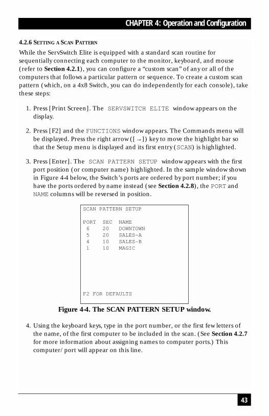
3. Press [Enter]. The SCAN PATTERN SETUP window appears with the firstport position (or computer name) highlighted. In the sample window shownin Figure 4-4 below, the Switch’s ports are ordered by port number; if youhave the ports ordered by name instead (see Section 4.2.8), the PORT andNAME columns will be reversed in position.
Figure 4-4. The SCAN PATTERN SETUP window.
4. Using the keyboard keys, type in the port number, or the first few letters ofthe name, of the first computer to be included in the scan. (See Section 4.2.7for more information about assigning names to computer ports.) Thiscomputer/port will appear on this line.
SCAN PATTERN SETUP
PORT SEC NAME6 20 DOWNTOWN5 20 SALES-A4 10 SALES-B1 10 MAGIC
F2 FOR DEFAULTS

44
SERVSWITCH ELITE™
5. Press the [Tab] or right-arrow ([→]) key to move the highlight bar to theSEC column and use the keyboard keys to enter a time value in seconds (upto 255) that you want this computer to be connected to the console (viewableon the monitor) before the Switch switches to the next computer in the scan.
To delete a single port from the list, enter “0” (zero) seconds here. Todelete a whole set of unwanted ports at the end of the scan list, which is wheremost of them end up after you’ve brought together your list of desired portsanyway, place the highlight bar on the topmost port to be removed and pressthe [Delete] key (not the [Del] key on the numeric keypad). The highlightedport and all ports below it will be removed from the list.
6. Press the down-arrow ([↓]) key to move the highlight bar to the next line.
7. Repeat steps 5 through 7 as necessary for your remaining computers.
8. When you’ve finished setting the scan pattern, press [Enter]. The new scanpattern supersedes the standard scan or any previous custom scan. You canpress [Esc] (escape) at any time prior to pressing [Enter] to retain theprevious scan pattern. Pressing the [F2] key will return all PORT and SECvalues to their factory defaults.
To exit the on-screen menus in order to test your new scan pattern, press [Esc].

45
CHAPTER 4: Operation and Configuration
4.2.7 ASSIGNING UNIQUE NAMES TO THE COMPUTERS AND SLAVES IN THE SYSTEM
It might be helpful to assign unique names to each computer and slave in yourServSwitch Elite system as a means of easy identification. For example, in a networkenvironment, the names can be the same as those assigned in the network for eachcomputer. Assign names as follows:
1. Press [Print Screen]. The SERVSWITCH ELITE window appears on thedisplay.
2. Press [F2] and the FUNCTIONS window appears. The Commands menu willbe displayed. Press the right arrow ([→]) key to move the highlight bar sothat the Setup menu is displayed.
3. Using the up- and down-arrow ([↑] and [↓]) keys, move the highlight bar toNAMES.
4. Press [Enter]. The PORT NAMING window appears:
Figure 4-5. The PORT NAMING window.
PORT NAMING
PORT NAME1 MAGIC2 CENTRALOFC3 SALES-C4 SALES-B5 SALES-A6 DOWNTOWN7 FOREIGN8

46
SERVSWITCH ELITE™
5. Using the up- and down-arrow ([↑] and [↓]) keys, move the highlight bar tothe PORT entry that you want to give a name or change the name of. Type in aname up to 12 alphanumeric characters long; valid characters are theuppercase letters “A” through “Z”—you can type lowercase letters, but they’llautomatically be converted to uppercase—the digits “0” through “9,” and the“–” (dash, hyphen, minus) character. Press [Backspace] to delete an incorrectentry or an entry for a device that has been removed from the system. Repeatthis step as necessary.
NOTEBefore you can name computers attached to a slave Switch, you have to tel l the master Switch that the slave is, in fact, a slave; seeSection 4.2.10.
6. Press [Enter] to save the computer name(s) in NVRAM. You can press [Esc](escape) at any time prior to pressing [Enter] to cancel the operation.

47
CHAPTER 4: Operation and Configuration
4.2.8 CHANGING THE MENU ATTRIBUTES
The menus and windows displayed on the monitor can be altered in visualappearance to suit the particular use of the system (and on a 4x8 Switch, you cando so independently for each console). Certain adjustments can be made to themenus so that:
• The menu is positioned in a convenient location on the display.
• The computers are listed by port or by name, whichever is desired, in theappropriate menus.
• The character height is suitable for display.
• The colors are suitable.
• The SERVSWITCH ELITE window appears on the display for a certainperiod of time.
To change attributes of the on-screen menus, take these steps:
NOTEIt is possible, when you change the menu attributes, to distort theappearance of the menus/windows so that they are hard or impossibleto read, which obviously makes it difficult to correct the problem. If thisoccurs, you can reset the ServSwitch Elite to its factory-default valuesfor all options accessible through the on-screen display by pressing andreleasing [Esc] (escape) twice, then [Print Screen], then [F10], then theletter [Y], then [Enter].
1. Press [Print Screen]. The SERVSWITCH ELITE window appears on thedisplay.
2. Press [F2] and the FUNCTIONS window appears. The Commands menu willbe displayed. Press the right arrow ([→]) key to move the highlight bar sothat the Setup menu is displayed.
3. Using the up- and down-arrow ([↑] and [↓]) keys, move the highlight bar toATTRIBUTES.

48
SERVSWITCH ELITE™
4. Press [Enter]. The PHYSICAL ATTRIBUTES window appears:
Figure 4-6. The PHYSICAL ATTRIBUTES window.
5. Highlight any setting you want to change and use the [+] and [–] keys to cycleto the desired value. As you select different values, the effect of the changes isreflected immediately on the display. Repeat this step as necessary.
The attributes whose values you can change include:
Attribute Effect on Menu/Window Appearance
Resolution Affects the size of the menus and windows as they appear onthe display. Choose from values of 320, 480, and 640; the lowerthe value, the larger the size. The factory-default value is 640.
Height Affects the size of the text in the menus and windows. Thelarger the value, the larger the text. Possible settings are 1(1 pixel) to 63 (63 pixels). The factory-default value is 16.
Horizontal Affects the left-to-right positioning of the menus and windowson the display. Possible settings are 1 (1 pixel from the far left)to 127 (127 pixels from the far left, which is as far right as it willgo). The factory-default value is 5.
Vertical Affects the top-to-bottom positioning of the menus andwindows on the display. Possible settings are 1 (1 pixel fromthe top) to 255 (255 pixels from the top, which is as far downas it will go). The factory-default value is 11.
PHYSICAL ATTRIBUTES
RESOLUTION 640HEIGHT 16HORIZONTAL 12VERTICAL 7
BACKGROUND 1HIGHLIGHT 4TEXT 7
DELAY TIME 0ORDER PORT

49
CHAPTER 4: Operation and Configuration
Background Determines the background color of the menus and windows.Possible choices are 0 (black), 1 (blue), 2 (light green), 3(cyan), 4 (red), 5 (magenta), 6 (yellow), and 7 (white). Thefactory-default value is 1 (blue).
Highlight Determines the color of the highlight bar appearing in themenus and windows. Possible choices are 0 through 7 as listedabove. The factory-default value is 4 (red).
Text Determines the color of the text appearing in the menus andwindows. Possible choices are 0 through 7 as listed above. Thefactory-default value is 6 (yellow).
Delay Time The time in seconds that elapses after you press [Print Screen]before the SERVSWITCH ELITE window appears on screen.The factory-default value is 0 (zero, no delay). You can increasethis delay if you find the window becoming a distraction whenyou perform simple computer-switching operations at thekeyboard.
Order Determines the order in which the computers are listed in themenus and windows: numerically by port number (the factory-default value), or alphabetically by assigned name.
NOTEBefore you take a formerly autonomous singleSwitch and attach it as a slave to a master Switch, itis very important that you set Order to “PORT” onthat slave Switch; the system could malfunction ifyou don’t. In general, we recommend that you resetany formerly autonomous Switch to its factorydefaults (see the note on page 47) before installing itas a slave.
6. When you’ve completed all your desired adjustments, press [Enter] to savethe changes to NVRAM. You can press [Esc] (escape) at any time prior topressing [Enter] to cancel the operation and retain the previous settings.

50
SERVSWITCH ELITE™
4.2.9 CHANGING THE ATTRIBUTES OF THE STATUS FLAG
The small on-screen box called the “status flag” indicates the currently connectedcomputer and can be set to appear on the screen whenever the system is operating.You can alter how and where the flag appears on the screen (on a 4x8 Switch, youcan do so independently for each console) by changing one or more of thefollowing attributes:
• Its appearance on the screen (none, timed, or constant);
• Its position on the screen; or
• Its color and opaqueness.
To change the flag’s attributes, take these steps:
1. Press [Print Screen]. The SERVSWITCH ELITE window appears on thedisplay.
2. Press [F2] and the FUNCTIONS window appears. The Commands menu willbe displayed. Press the right arrow ([→]) key to move the highlight bar sothat the Setup menu is displayed.
3. Using the up- and down-arrow ([↑] and [↓]) keys, move the highlight bar toFLAG.
4. Press [Enter]. The FLAG CONFIGURATION window appears:
Figure 4-7. The FLAG CONFIGURATION window.
FLAG CONFIGURATION
ENABLED NAMES ONROW 14COLUMN 1COLOR 2TEXT 0MODE TRANSPARENT

51
CHAPTER 4: Operation and Configuration
5. Highlight the setting(s) you want to change and use the [+] and [–] keys tocycle to the desired value. Repeat this step as necessary.
The flag attributes whose values you can change include:
Attribute Effect on Status-Flag Appearance
Enabled FLAG OFF = Flag does not appearPORTS ON = Flag indicates the number of the connected port
(the factory-default value)NAMES ON = Flag indicates the connected device by namePORTS TIMED = Port number is displayed for 5 seconds after
connectionNAMES TIMED = Name is displayed for 5 seconds after
connection
Row Determines the flag’s vertical position on the screen. This willalways depend on the vertical position set for the menuwindows (see Section 4.2.8): The status flag will be displayedwhere one of the rows of text in the windows would be. Validvalues range from 0 (top row) to 14 (bottom row). The factory-default value is 0.
Column Determines the flag’s horizontal position on the screen. Thiswill always depend on the horizontal position set for the menuwindows (see Section 4.2.8): The status flag will be displayedwhere one of the text columns in the windows would be. Validvalues range from 1 (far-left column) to 25 (far-right column).The factory-default value is 1.
Color Determines the flag’s background color. Possible choices are0 (black), 1 (blue), 2 (light green), 3 (cyan), 4 (red),5 (magenta), 6 (yellow), and 7 (white). The factory-defaultvalue is 2 (light green).
Text Determines the flag’s text color. Possible choices are 0 through7 as listed above. The factory-default value is 0 (black).
Mode Determines whether the background can be seen through theflag (“TRANSPARENT”) or not (“OPAQUE,” the defaultsetting).
6. When you’ve completed making all your desired adjustments, press [Enter] tosave the changes to NVRAM. You can press [Esc] (escape) at any time prior topressing [Enter] to cancel the operation and retain the previous settings.
To exit the on-screen menus in order to test your new status-flag attributes, press[Esc].

52
SERVSWITCH ELITE™
4.2.10 ASSIGNING SPECIFIC DEVICE TYPES
In situations where one or more of the computers attached to the ServSwitch Eliteneed a special type of monitor or device, it may be necessary to assign that devicetype to the port number associated with that computer. Also, when you cascadeyou must make the master Switch aware of the slaves through this assignment.Assign a device type this way:
1. Press [Print Screen]. The SERVSWITCH ELITE window appears on thedisplay.
2. Press [F2] and the FUNCTIONS window appears. The Commands menu willbe displayed. Press the right arrow ([→]) key to move the highlight bar sothat the Setup menu is displayed.
3. Using the up- and down-arrow ([↑] and [↓]) keys, move the highlight bar toDEVICES.
4. Press [Enter]. The MONITOR SETTINGS window appears:
Figure 4-8. The MONITOR SETTINGS window.
MONITOR SETTINGS
PORT MONITOR1 SVGA2 SVGA3 85154 SVGA5 DEFAULT6 DEFAULT7 DEFAULT8 8PORT

53
CHAPTER 4: Operation and Configuration
5. To assign to a monitor or device type, highlight the port you want and use the[+] and [–] keys to cycle to the value that corresponds to the particularmonitor or slave type.
NOTEThe proper setting for a slave ServSwitch Elite is “8PORT.” It is alsopossible to choose “4PORT” because some compatible Compaq and HPKVM-switch models have four computer ports. If you install one of theseother units as a slave, choose “4PORT” for the corresponding port inthis menu.
There is also a reserved “10PORT” setting, designed with futureServSwitch Elite system capabilities in mind. Do not select “10PORT.”
6. When you’ve completed making all your desired adjustments, press [Enter] tosave the changes to NVRAM. You can press [Esc] (escape) at any time prior topressing [Enter] to cancel the operation and retain the previous settings.
4.2.11 SETTING SECURITY OPTIONS
Advanced server applications should usually be protected against unauthorizeduse. By engaging the ServSwitch Elite’s security features, you can “lock” thekeyboard, mouse, and monitor (independently for each console on the 4x8model), requiring users who want to use the console to type a password before theconsole will resume operating normally. You can lock the console manually, or youcan set the Switch to lock the console after a time delay (inactivity timeout)expires. You can also set the unit’s security parameters without locking the console,and you can even set the unit to blank the monitor without password protection. Todo any of these things, take these steps:
1. Press [Print Screen]. The SERVSWITCH ELITE window appears on thedisplay.
2. Press [F2] and the FUNCTIONS window appears. The Commands menu willbe displayed. Press the right arrow ([→]) key to move the highlight bar sothat the Setup menu is displayed.
3. Using the up- and down-arrow ([↑] and [↓]) keys, move the highlight bar toSECURITY.
4. Press [Enter]. The SECURITY CONFIGURATION window appears (seeFigure 4-9 below). At first, the only field you can highlight or access isPASSWORD; you must always type in the current password in order to accessthe other fields.

54
SERVSWITCH ELITE™
5. Type in the password and press [Enter]. (The factory-default password is“ELITE”; because [Caps Lock] is disabled while the Switch’s display is onscreen, you’ll have to hold down [Shift] while you type this in.) The rest ofthe window components become accessible:
Figure 4-9. The SECURITY CONFIGURATION window.
6. Use the up- and down-arrow ([↑] and [↓]) keys to move the highlight bar toany security feature you want to set differently:
• To set a new password for the Switch, highlight NEW PASSWORD, type in anew password, and press [Enter]. (Passwords can be up to 8 characters long,can include any printable character, and are case-sensitive.) The highlightbar will move to REPEAT NEW and you will have to type the password inagain to confirm your choice.
CAUTION!Be very careful to memorize your new password or record it in asafe place. If you forget or lose your password, you will have tocall Black Box Technical Support for instructions on how torecover your system.
If you aren’t all that concerned about security, but would like to blank themonitor when it isn’t in use, you can press just [Enter] twice with the NEWPASSWORD and REPEAT NEW fields empty. This “nullifies” the password,so to speak; until you set a password with at least one character in it,pressing any keyboard key will unlock the console. The screen-saver andother console-locking functions will be active, but the system will not besecure.
SECURITY CONFIGURATION
PASSWORD
NEW PASSWORDREPEAT NEW
TIME DELAY OFFMODE SCREENTEST

55
CHAPTER 4: Operation and Configuration
• To set a delay period that the Switch will wait before locking your consoleafter detecting that its keyboard and mouse have become idle, highlightTIME DELAY, then choose either “OFF” (automatic lockout disabled, thefactory-default setting) or a numeric value in seconds from “1” (the Switchlocks out the console when its keyboard and mouse become idle for onesecond) to “99” (the Switch waits for 1 minute and 39 seconds to lock theconsole after the keyboard and mouse become idle). You can do this eitherby typing in the number of seconds (or the letter “O” or the digit zero forOFF) or by using the [+] and [–] keys to increment or decrement the valueuntil you reach your desired setting (from “1,” press [–] to reach OFF thisway).
• To choose how the Switch goes about blanking the monitor screen whenthe console is locked, highlight MODE, use the [+] and [–] keys to selecteither ENERGY or SCREEN. Use ENERGY mode with EnergyStar™ compliantmonitors that go into “sleep mode” (power-saver state) after a period ofinactivity elapses; in this mode, the Switch blanks the monitor by causing itto go into sleep mode. Use SCREEN mode with monitors that aren’tEnergyStar compliant; in this mode, the Switch sends the monitor a BlackBox screen saver image instead of the video signal from the selectedcomputer.
CAUTION!Do not use ENERGY mode if your monitor is not EnergyStarcompliant. You could damage your monitor.
6. If you’re ready to lock the console right now, use the down-arrow ([↓]) key tomove the highlight bar to TEST and press [Enter]. The Switch willimmediately lock the console in the chosen MODE.
If you just want to exit this screen and save the security settings you’ve justchosen to NVRAM, press [Enter] with the highlight bar on anything otherthan TEST.

56
SERVSWITCH ELITE™
4.3 Resetting the ServSwitch EliteIf your keyboard or mouse locks up, and resetting the CPU’s keyboard and mouseports doesn’t help (see Section 4.2.4), you can trying pushing the Reset button onthe ServSwitch Elite’s rear panel in order to reset the Switch. Doing so might allowyou to recover the device settings without rebooting your computers.
4.4 Making Connections Under PowerYou can connect additional computers or slave Switches to the ServSwitch Elitewhile it is running. Attach computers as normal; when you attach a slave, makesure to connect the keyboard-extension cable last, because the master Switchinterprets the keyboard connection as the slave Switch powering up.
When you power up the newly connected computers, the Switch recognizesthem, and you can select them without taking any additional steps. After you powerup the newly connected slaves, you have to tell the master Switch what they are (seeSection 4.2.10), but once you do so the slaves are also ready for operation.
You can also disconnect and reconnect the mouse or keyboard to the Switchwhile the system is powered up. When you connect a new device, the Switchrecognizes it, and configures it to the settings required by the currently selectedcomputer. This feature makes it possible for you to replace failed devices withouthaving to restart the system.
Whenever you attach new computers or slaves, or whenever you swap out themouse or keyboard, you should save the Switch’s hardware-configuration settings.If you do not save the settings, they will be lost when the Switch loses power or isturned off. For more information, see Section 4.2.3.
4.5 Power-Outage RecoveryUsing intelligent keyboard and mouse emulation in ways similar to those itemploys for enabling connections under power (see Section 4.4), the ServSwitchElite will help your computers recover from power outages, if—and this is veryimportant—the Switch is plugged into a UPS (uninterruptible power supply). (Ifthe Switch has lost power along with the computers, it will have to get itself back upwhen power is restored and might not be able to help your computers.) If a Switchis operating when power returns to the attached computers, all of the computersthat are designed to reboot themselves automatically (without user intervention)will do so. The Switch generates responses to ensure that the reboot is successfuland that the Switch is ready to switch between computers when regular operationresumes.

57
CHAPTER 5: Troubleshooting
5. Troubleshooting
5.1 Common ProblemsHere are some difficulties that people sometimes have with the ServSwitch Elite,along with possible causes and solutions. If you don’t see your problem here, or ifthe suggestions here don’t help you, call Black Box Technical Support (seeSection 5.2).
No on-screen display or video on any computer.
1. No power to ServSwitch Elite or monitor? Check the power switches;reconnect the power cables; make sure the AC outlet is actually providingpower.
2. Loose monitor connection? Reconnect monitor.
3. Current colors or setup of on-screen display make the display unviewable?Reset the display to its factory defaults (see the note on page 47).
No video on one particular computer.
1. Computer off or unplugged? Power up the computer connected to that port.
2. Loose video connection? Reconnect video cable.
3. Defective video cable? Replace video cable.
Can’t select computers.
1. Computer off or unplugged? Power up the computer connected to that port.
2. Keyboard did not initialize? Reset keyboard (and mouse) with ServSwitchElite’s rear-panel reset switch.
3. Keyboard incompatible? Replace keyboard.
Boot-time keyboard errors for all computers.
1. Loose keyboard connection? Check that all cables are well seated.
2. Incompatible or defective keyboard? Replace keyboard.
Boot-time keyboard error for one particular computer.
1. Loose keyboard connection? Check that all cables are well seated; make surethat mouse and keyboard cables are not swapped.
2. Defective keyboard-extension cable? Replace cable.

58
SERVSWITCH ELITE™
Keyboard strokes shifted (swaps upper case for lower case).
Computer left keyboard in shifted state when last connected. Press both [Shift]keys.
Boot-time mouse errors for all computers.
1. Loose mouse connection? Check that all cables are well seated; make surethat mouse and keyboard cables are not swapped.
2. Incompatible or defective mouse? Replace mouse with PS/2 style mouse ormouse compatible with CPU mouse port.
Boot-time mouse error for one particular computer.
1. Loose mouse connection? Check that all cables are well seated; make surethat mouse and keyboard cables are not swapped.
2. Defective mouse-extension cable? Replace cable.
3. Using serial port on computer? Either install serial-mouse adapter kit(KV7150) or replace mouse with PS/2 style mouse or mouse compatible withCPU mouse port.
Mouse behaves erratically.
Computer left mouse in indeterminate state. Reset CPU mouse port (seeSection 4.2.4) or reset ServSwitch Elite (see Section 4.3).
Mouse pointer frozen on display.
Mouse not initialized. Reset CPU mouse port (see Section 4.2.4) or resetServSwitch Elite (see Section 4.3).
Keyboard or mouse input appears on more than one computer simultaneously.
ServSwitch Elite is in broadcast mode. Go into on-screen display and turnbroadcast mode off (see Section 4.2.5).
ServSwitch Elite switches from one computer to the next at will.
ServSwitch Elite is in scan mode. Halt scanning by pressing any key or movingmouse.

59
CHAPTER 5: Troubleshooting
5.2 Calling Black BoxIf you determine that your ServSwitch Elite is malfunctioning, do not attempt to alteror repair the unit. It contains no user-serviceable parts. Contact Black Box TechnicalSupport at 724-746-5500.
Before you do, make a record of the history of the problem. We will be able toprovide more efficient and accurate assistance if you have a complete description,including:
• all information displayed in the VERSION window (see Section 4.2.2).
• the nature and duration of the problem.
• when the problem occurs.
• the components involved in the problem—that is, what type of computers,what type of keyboard, brand of mouse, make and model of monitor, etc.
• any particular application that, when used, appears to create the problem ormake it worse.
• the results of any testing you’ve already done.
5.3 Shipping and PackagingIf you need to transport or ship your ServSwitch Elite:
• Package it carefully. We recommend that you use the original container.
• Before you ship the unit back to Black Box for repair or return, contact us toget a Return Authorization (RA) number.

60
SERVSWITCH ELITE™
Appendix A: Keyboard Commandsfor the On-Screen Display
You can use these keys and key sequences to navigate the ServSwitch Elite’s on-screen menus and to select on-screen options:
[Print Screen] Pressing once activates on-screen display on single or masterSwitch; for multiple keypresses, see Table 4-2 on page 31.
[Esc] (escape) Aborts any changes without executing them; also escapes fromcurrent menu.
[Enter] Executes the current selection or command or saves changesthat have been made.
[≠] (up-arrow) Moves up one field or row in the current menu.
[Ø] (down-arrow) Moves down one field or row in the current menu.
[Æ] (right-arrow) or [Tab]Moves one field or column to the right (wrapping downward at right edge), orhighlights adjacent menu
[¨] (left-arrow) or [Shift] + [Tab]Moves one field or column to the left (wrapping upward at left edge), or highlightsadjacent menu
[+] (plus)Increases or cycles forward the value in the currently highlighted field.
[–] (minus, dash, hyphen)Decreases or cycles backward the value in the currently highlighted field.
[Page Up] Displays the previous screen of a multiscreen display.
[Page Down] Displays the next screen of a multiscreen display.
[Home] Displays the first screen of a multiscreen display.
[End] Displays the last screen of a multiscreen display.

61
APPENDIX B: Upgrading the Firmware
Appendix B: Upgrading the Firmware
The ServSwitch Elite’s processor firmware is stored in an EPROM chip mountedon the Switch’s motherboard. If you ever need to upgrade the Switch’s firmware,you will have to replace this chip. To do so, take these steps:
CAUTION!The EPROM chip and other components inside the ServSwitch Elite canbe damaged by static electricty, so take every reasonable precautionagainst it. At the very least, discharge yourself on a metallic surfacebefore opening the Switch’s access panel; if possible, stand on an anti-static mat and wear a grounding strap or anti-static gloves.
We recommend that you perform this procedure when you doscheduled server maintenance, or when you power down the attachedcomputers for whatever other reason. This is because many computerscan’t handle the loss of keyboard and mouse signals that occurs whenthe Switch is turned off, and will malfunction otherwise.
1. Get the tools you will need, a small Phillips screwdriver and a chip puller. (Ifyou don’t have a chip puller, you can use a small flat-blade screwdriver.)
2. Save the current hardware settings of the ServSwitch Elite system (seeSection 4.2.3).
3. Very important: Turn the Switch off, unplug its power cord from the ACoutlet, and then detach the cord from the Switch.
4. Look at the bottom of the unit; you will see an access panel in one corner.Use the Phillips screwdriver to unscrew the two screws that hold the panel on,then remove the panel. You should now be able to see the EPROM andNVRAM chips and the unit’s main DIP switch, as shown in Figure A-1 on thenext page.
5. If you have a chip puller, use it to carefully remove the EPROM from its socket.To remove the chip with a flat-blade screwdriver, gently and carefully pry thechip upward first at one end, then at the other, alternating until the chipcomes off. Use extreme caution to avoid damaging the chip, its IC socket, or thecircuit board.

62
SERVSWITCH ELITE™
Figure A-1. The location of the EPROM.
6. Carefully insert the new firmware EPROM into the socket, making sure thatthe orientation notch on the EPROM chip matches the outline of the socketand drawing on the circuit board (refer to Figure A-1 on the previous page).Press firmly to make sure that the chip is seated properly in the IC socket,then do one last visual inspection to make sure that all of the pins on the newchip go straight into the socket.
7. Replace the access panel, screw the screws back in, and return the ServSwitchElite to service. If it does not appear to work properly when you hook it backinto the system, call Black Box for technical support.
EPROM
NVRAM

63
APPENDIX C: RS/6000 Handling
Appendix C: RS/6000 HandlingThe IBM RISC System/6000, better known by its shorter name “RS/6000,” differssignificantly from standard PC-type computers, but the ServSwitch Elite is designedto support most RS/6000 systems.
The RS/6000 utilizes a slightly different power-up sequence on the keyboard toallow identification of the RS/6000 series of keyboards. The ServSwitch Eliterecognizes this fact and responds accordingly.
RS/6000 video is even more varied than video is in the PC world, at least interms of the electrical and physical interfaces that have been built into differentmodels. The RS/6000 can adapt to most PC-style video standards (VGA, SVGA,etc.), and also uses a few video-transmission schemes that PCs usually don’t. Inparticular, the RS/6000 models with 3C3 video ports use a video format called“sync on green.” In this format, the composite sync signal and its ground arecarried on the same wire(s) as the green color signal and its ground. Any graphicssystem that uses sync on green will require an adapter in order to be attached tothe ServSwitch Elite. In the case of the RS/6000, the RS/6000 Converter Kit(KV7160A) is designed for this purpose.
Another consideration is the physical video connector. Most contemporary PCshave HD15 connectors, but many RS/6000 models have the 13W3 connectors thatare also found on Sun Microsystems® and SGI® machines. Even though theseRS/6000 models use the same type of video format as regular PCs—so you won’tneed the KV7160A Converter—you will still need the special HD15-to-13W3 cablein the EHN6000-ELITE cable kit to attach an RS/6000 with a 13W3 connector tothe Switch.

64
SERVSWITCH ELITE™
Appendix D: Interface Pinouts
D.1 IBM PC/AT Compatible KeyboardPinout on 5-pin DIN connectors:
Pin Signal/Circuit Signal SignalName Function Source
1 Keyboard Clock Timing Computer
2 Keyboard Data Data Keyboard
3 Keyboard Reset1 Control Computer
4 Ground Ground n/a
5 +5 VDC Voltage Computer
1This line/signal was used by XT and very early AT computers to reset the keyboard.Contemporary AT compatible computers either do not use it or do not connect it.
D.2 IBM PC/AT Compatible Serial MouseTIA-574 pinout of EIA/TIA RS-232-C/D on DB9 (DE9) connectors:
Pin Signal/Circuit Signal SignalName Function Source
1 Received Data Data Mouse
3 Transmitted Data Data Computer
4 Data Terminal Ready Control Computer
5 Signal Ground Ground n/a
7 Request to Send Control Computer
(All other pins are not connected or not used.)
1
2 2
3 3
4 45 5
FemaleMale
1
1 Male Female5
6 9
5 1
9 6

65
APPENDIX D: Interface Pinouts
D.3 IBM PS/2 Compatible Keyboard and MouseStandard pinout on 6-pin mini-DIN connectors:
Pin Signal/Circuit Signal SignalName Function Source
1 Keyboard or Mouse Data Keyboard or MouseData
2 Reserved1 n/a n/a
3 Ground Ground n/a
4 +5 VDC Voltage Computer
5 Keyboard or Mouse Timing ComputerClock
6 Reserved1 n/a n/a
1These pins are normally not used or not connected, but some KVM switches (not including theServSwitch Elite) use them to carry the RS-232 serial transmit data signal and signal groundrespectively, in order to be more easily adaptable for use with serial mice and serial mouseports.
1 2 2
3 44 3
5 6 6 5FemaleMale
1

66
SERVSWITCH ELITE™
D.4 IBM Video Graphics Array (VGA), Super Video Graphics Array (SVGA)Original standard pinout on HD15 (DA15) connectors:
Pin Signal/Circuit Signal SignalName Function Source
1 Red Data Computer
2 Green Data Computer
3 Blue Data Computer
4 ID 21 Control Monitor
5 No Connection2
6 Red Return Ground n/a
7 Green Return Ground n/a
8 Blue Return Ground n/a
9 Key (No Pin)3
10 Ground4 Ground n/a
11 ID 0 (Ground)5 Control Monitor
12 ID 1 (N/C)5 Control Monitor
13 Horizontal Sync Timing Computer
14 Vertical Sync Timing Computer
15 ID 36 Control Monitor
1This pin is sometimes not used or not connected.2This pin is sometimes used as a ground.3In standard implementations, this pin is not only not connected, the space where it would be inthe connectors is simply left blank.
4This is the ground for all of the non-video signals.5In the original VGA standard, if the computer senses that Pin 11 is a ground and Pin 12 is notconnected, it assumes a color monitor and outputs color VGA. If it senses that Pin 11 is notconnected and Pin 12 is a ground, it assumes a monochrome monitor and outputs “VGAmonochrome.” (Often computers check only Pin 11.)
6This pin is very rarely used and is most often not connected at all.
1
6 10 10 6
Male Female5
11 15
5 1
15 11

67
CHAPTER

68
SERVSWITCH ELITE™ NOTES

69
CHAPTERNOTES

70
SERVSWITCH ELITE™ NOTES

71
CHAPTERNOTES